EP4421366A1 - Electric valve control device and electric valve device - Google Patents
Electric valve control device and electric valve device Download PDFInfo
- Publication number
- EP4421366A1 EP4421366A1 EP22879637.1A EP22879637A EP4421366A1 EP 4421366 A1 EP4421366 A1 EP 4421366A1 EP 22879637 A EP22879637 A EP 22879637A EP 4421366 A1 EP4421366 A1 EP 4421366A1
- Authority
- EP
- European Patent Office
- Prior art keywords
- electric valve
- valve
- opening degree
- control device
- electric
- Prior art date
- Legal status (The legal status is an assumption and is not a legal conclusion. Google has not performed a legal analysis and makes no representation as to the accuracy of the status listed.)
- Pending
Links
Images


Classifications
-
- F—MECHANICAL ENGINEERING; LIGHTING; HEATING; WEAPONS; BLASTING
- F16—ENGINEERING ELEMENTS AND UNITS; GENERAL MEASURES FOR PRODUCING AND MAINTAINING EFFECTIVE FUNCTIONING OF MACHINES OR INSTALLATIONS; THERMAL INSULATION IN GENERAL
- F16K—VALVES; TAPS; COCKS; ACTUATING-FLOATS; DEVICES FOR VENTING OR AERATING
- F16K31/00—Actuating devices; Operating means; Releasing devices
- F16K31/02—Actuating devices; Operating means; Releasing devices electric; magnetic
- F16K31/04—Actuating devices; Operating means; Releasing devices electric; magnetic using a motor
-
- F—MECHANICAL ENGINEERING; LIGHTING; HEATING; WEAPONS; BLASTING
- F16—ENGINEERING ELEMENTS AND UNITS; GENERAL MEASURES FOR PRODUCING AND MAINTAINING EFFECTIVE FUNCTIONING OF MACHINES OR INSTALLATIONS; THERMAL INSULATION IN GENERAL
- F16K—VALVES; TAPS; COCKS; ACTUATING-FLOATS; DEVICES FOR VENTING OR AERATING
- F16K37/00—Special means in or on valves or other cut-off apparatus for indicating or recording operation thereof, or for enabling an alarm to be given
-
- F—MECHANICAL ENGINEERING; LIGHTING; HEATING; WEAPONS; BLASTING
- F25—REFRIGERATION OR COOLING; COMBINED HEATING AND REFRIGERATION SYSTEMS; HEAT PUMP SYSTEMS; MANUFACTURE OR STORAGE OF ICE; LIQUEFACTION SOLIDIFICATION OF GASES
- F25B—REFRIGERATION MACHINES, PLANTS OR SYSTEMS; COMBINED HEATING AND REFRIGERATION SYSTEMS; HEAT PUMP SYSTEMS
- F25B41/00—Fluid-circulation arrangements
- F25B41/30—Expansion means; Dispositions thereof
- F25B41/31—Expansion valves
- F25B41/34—Expansion valves with the valve member being actuated by electric means, e.g. by piezoelectric actuators
- F25B41/35—Expansion valves with the valve member being actuated by electric means, e.g. by piezoelectric actuators by rotary motors, e.g. by stepping motors
-
- Y—GENERAL TAGGING OF NEW TECHNOLOGICAL DEVELOPMENTS; GENERAL TAGGING OF CROSS-SECTIONAL TECHNOLOGIES SPANNING OVER SEVERAL SECTIONS OF THE IPC; TECHNICAL SUBJECTS COVERED BY FORMER USPC CROSS-REFERENCE ART COLLECTIONS [XRACs] AND DIGESTS
- Y02—TECHNOLOGIES OR APPLICATIONS FOR MITIGATION OR ADAPTATION AGAINST CLIMATE CHANGE
- Y02B—CLIMATE CHANGE MITIGATION TECHNOLOGIES RELATED TO BUILDINGS, e.g. HOUSING, HOUSE APPLIANCES OR RELATED END-USER APPLICATIONS
- Y02B30/00—Energy efficient heating, ventilation or air conditioning [HVAC]
- Y02B30/70—Efficient control or regulation technologies, e.g. for control of refrigerant flow, motor or heating
Definitions
- the present invention relates to an electric valve control device and an electric valve device including the electric valve control device.
- Patent Literature 1 discloses an example of an electric valve of the related art.
- the electric valve is incorporated in a refrigeration cycle system of an air conditioner.
- the electric valve includes a valve body, a valve member, and a stepping motor for moving the valve member.
- the stepping motor includes a rotor and a stator. When a pulse is input to the stepping motor, the rotor rotates. In accordance with the rotation of the rotor, the valve member moves and the valve opening degree of the electric valve is changed.
- the electric valve is controlled by an electric valve control device.
- the electric valve control device changes the valve opening degree of the electric valve within a range from a minimum opening degree to a maximum opening degree (for example, a range of 0% to 100%).
- the electric valve control device has information indicating the valve opening degree of the electric valve at present (present valve opening degree information).
- the electric valve control device receives an instruction to change the valve opening degree of the electric valve from an air conditioning control device, the electric valve control device inputs the number of pulses calculated on the basis of the present valve opening degree information to the stepping motor to change the valve opening degree of the electric valve to a valve opening degree specified by the instruction.
- Patent Literature 1 Japanese Unexamined Patent Application Publication No. 2012-13197
- the valve opening degree indicated in the present valve opening degree information may differ from the actual valve opening degree of the electric valve.
- the actual valve opening degree of the electric valve may be larger than the valve opening degree indicated in the present valve opening degree information.
- the rotor may be detached from a thread mechanism that changes the rotation of the rotor into a linear movement, or a step-out may occur in the stepping motor. Even in an electric valve including a motor of a type differing from the stepping motor, malfunctioning may occur as a result of the position of a rotor of the motor existing beyond the position corresponding to the maximum opening degree.
- an object of the present invention to provide an electric valve control device capable of suppressing the position of a rotor of a motor from existing beyond a position corresponding to a maximum opening degree of an electric valve and an electric valve device including the electric valve control device.
- an electric valve control device for controlling an electric valve including a motor, in which the electric valve control device has present valve opening degree information indicating a present valve opening degree of the electric valve and changes a valve opening degree of the electric valve within a range from a minimum opening degree to a maximum opening degree based on the present valve opening degree information, and in which, when the electric valve control device detects an abnormality in the electric valve, the electric valve control device sets the maximum opening degree in the present valve opening degree information.
- the electric valve control device include a non-volatile storage section that stores state information indicating a state of the electric valve at a previous end-of-control time and previous valve opening degree information indicating a valve opening degree of the electric valve at the previous end-of-control time, in which, when the state information is information indicating a normal end when control of the electric valve is started, the electric valve control device sets in the present valve opening degree information the valve opening degree indicated in the previous valve opening degree information, and sets in the state information information indicating an abnormal end, in which, when the state information is the information indicating the abnormal end when the control of the electric valve is started, the electric valve control device sets the maximum opening degree in the present valve opening degree information, and in which, when the state information is the information indicating the normal end when the control of the electric valve is started, and when no abnormality is detected in the electric valve after starting the control of the electric valve, the electric valve control device sets in the state information the information indicating the normal end when the control of the electric valve ends.
- an electric valve device includes the electric valve and the electric valve control device.
- the electric valve control device has the present valve opening degree information indicating the present valve opening degree of the electric valve, and changes the valve opening degree of the electric valve within the range from the minimum opening degree to the maximum opening degree on the basis of the present valve opening degree information.
- the electric valve control device detects an abnormality in the electric valve, the electric valve control device sets the maximum opening degree in the present valve opening degree information. Therefore, when the electric valve control device detects the abnormality in the electric valve, the electric valve control device assumes that the valve opening degree of the electric valve is the maximum opening degree regardless of the actual valve opening degree of the electric valve.
- the electric valve control device is capable of inhibiting the rotor from rotating in a valve opening direction beyond a position corresponding to the actual valve opening degree of the electric valve when the electric valve control device detects the abnormality.
- the electric valve control device is capable of suppressing the position of the rotor of the motor from existing beyond the position corresponding to the maximum opening degree.
- An electric valve device according to an embodiment of the present invention is described below with reference to Figs. 1 to 6 .
- An electric valve device 1 according to the present embodiment is used as, for example, a flow rate control valve that controls the flow rate of a refrigerant in a refrigeration cycle system of an air conditioner.
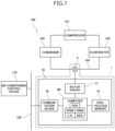
- Fig. 1 is a block diagram of an air conditioning system including an electric valve device according to the embodiment of the present invention.
- Fig. 2 is a sectional view of the electric valve device in Fig. 1 .
- Fig. 2 schematically shows a stator and an electric valve control device.
- Fig. 3 is a plan view of a valve stem holder, a stopper member, a rotor, and the stator of the electric valve device in Fig. 2 .
- Fig. 3 schematically shows the stator.
- Fig. 3 also schematically shows magnetic poles of the rotor.
- Fig. 4 is a diagram illustrating a computer, a motor driver, and a stepping motor of the electric valve device in Fig. 2 .
- Fig. 1 is a block diagram of an air conditioning system including an electric valve device according to the embodiment of the present invention.
- Fig. 2 is a sectional view of the electric valve device in Fig. 1 .
- Fig. 2 schematically shows
- FIG. 4A schematically shows a connection of the computer, the motor driver, and the stepping motor.
- Fig. 4B shows an example of correspondence between pulse and driving current that is supplied to the stator by the motor driver.
- Figs. 5 and 6 are each a flowchart showing an example of a process that is executed by the computer of the electric valve device in Fig. 2 .
- Fig. 1 shows an example of an air conditioning system 100 mounted on a vehicle.
- the air conditioning system 100 includes a compressor 101, a condenser 102, the electric valve device 1 (electric valve 5), and an evaporator 103, which are connected in this order through a pipe 105.
- the electric valve device 1 functions as an expansion valve.
- the air conditioning system 100 includes an air conditioning control device 110.
- the air conditioning control device 110 is connected to the electric valve device 1 and is capable of communication with the electric valve device 1.
- the air conditioning control device 110 uses the electric valve device 1 to control the flow rate of a refrigerant that flows through the pipe 105.
- the electric valve device 1 includes the electric valve 5 and an electric valve control device 70.
- the electric valve 5 includes a valve body 10, a can 20, a valve member 30, a driving mechanism 40, and a stator 60.
- the valve body 10 includes a body member 11 and a connecting member 13.
- the body member 11 has a circular columnar shape.
- the body member 11 includes a valve chamber 14.
- a first conduit 15 and a second conduit 16 are bonded to the body member 11.
- the first conduit 15 is disposed along a direction (left-and-right direction in Fig. 2 ) perpendicular to an axis L, and is connected to the valve chamber 14.
- the second conduit 16 is disposed along a direction of the axis L (up-and-down direction in Fig. 2 ), and is connected to the valve chamber 14 through a valve port 17.
- the valve port 17 is enclosed by a valve seat 18, which has a circular annular shape, in the valve chamber 14.
- the body member 11 has a fitting hole 11a having a circular shape.
- the fitting hole 11a is provided in the upper end surface of the body member 11.
- the inner peripheral surface of the fitting hole 11a includes a planar part 11d facing leftwards in Fig. 2 .
- a through hole 11b is provided in the bottom surface of the fitting hole 11a and communicates with the valve chamber 14.
- the connecting member 13 has a circular annular plate-like shape. The inner peripheral edge of the connecting member 13 is bonded to the upper end portion of the body member 11.
- the body member 11 and the connecting member 13 are made of a metal, such as an aluminum alloy, stainless steel, or brass.
- the can 20 is made of a metal, such as stainless steel.
- the can 20 has a circular cylindrical shape.
- the can 20 is open at the lower end and is closed at the upper end.
- the lower end of the can 20 is bonded to the outer peripheral edge of the connecting member 13.
- the valve member 30 includes a first stem portion 31, a second stem portion 32, and a valve portion 33.
- the first stem portion 31 has a circular columnar shape.
- the second stem portion 32 has a circular columnar shape.
- the diameter of the second stem portion 32 is smaller than the diameter of the first stem portion 31.
- the second stem portion 32 is provided coaxially and continuously with the upper end of the first stem portion 31.
- the valve member 30 includes a step portion 34 that is an annular plane facing upward.
- the step portion 34 is disposed in a part of the valve member 30 where the first stem portion 31 and the second stem portion 32 are continuously provided.
- the valve portion 33 has a substantially circular conical shape whose diameter decreasing from top to bottom.
- the valve portion 33 is provided coaxially and continuously with the lower end of the first stem portion 31.
- the valve portion 33 is disposed in the valve port 17.
- a variable throttle passage is formed between the valve portion 33 and the valve port 17.
- the valve portion 33 faces the valve seat 18. When the valve portion 33 is in
- the driving mechanism 40 moves the valve member 30 in the up-and-down direction (the direction of the axis L).
- the movement of the valve member 30 changes the opening degree of the valve port 17 (that is, the valve opening degree of the electric valve 5).
- the driving mechanism 40 includes a rotor 41, a valve stem holder 42, a guide bush 43, a stopper member 44, and a fixed member 45.
- the rotor 41 has a circular cylindrical shape.
- the outer diameter of the rotor 41 is slightly smaller than the inner diameter of the can 20.
- the rotor 41 is disposed inside the can 20.
- the rotor 41 is rotatable with respect to the valve body 10.
- the rotor 41 has a plurality of north (N) poles and a plurality of south (S) poles.
- the N poles and the S poles are disposed on the outer peripheral surface of the rotor 41.
- the N poles and the S poles each extend in the up-and-down direction.
- the N poles and the S poles are alternately arranged at equal angular intervals in the peripheral direction.
- the rotor 41 has, for example, twelve N poles and twelve S poles.
- the angle between adjacent N and S poles is 15 degrees.
- the valve stem holder 42 has a circular cylindrical shape.
- the valve stem holder 42 is open at the lower end and is closed at the upper end.
- the valve stem holder 42 is fitted to a fitting hole 41a of the rotor 41.
- the valve stem holder 42 rotates together with the rotor 41.
- a movable stopper 42s is disposed on the lower end portion of the outer peripheral surface of the valve stem holder 42 and is a protrusion extending radially outward.
- the valve stem holder 42 has a stem hole 42b.
- the stem hole 42b is provided in an upper wall portion 42a of the valve stem holder 42.
- the second stem portion 32 of the valve member 30 is disposed in the stem hole 42b movably in the direction of the axis L.
- a washer 46 is disposed on the lower surface of the upper wall portion 42a of the valve stem holder 42.
- a valve closing spring 47 is disposed between the washer 46 and the step portion 34 of the valve member 30.
- the valve closing spring 47 is a coil spring, and pushes the valve member 30 toward the valve seat 18.
- An internal thread 42c is formed on the inner peripheral surface of the valve stem holder 42.
- the movable stopper 42s is fixed with respect to the rotor 41.
- the guide bush 43 includes a base portion 43a and a supporting portion 43b.
- the base portion 43a has a circular cylindrical shape.
- the supporting portion 43b has a circular cylindrical shape.
- the outer peripheral surface of the base portion 43a has a planar part 43d.
- the base portion 43a is press-fitted into the fitting hole 11a of the body member 11, and the planar part 43d is in contact with the planar part 11d of the fitting hole 11a. Therefore, the central axis of the body member 11 and the central axis of the guide bush 43 coincide on the axis L, and the guide bush 43 is properly positioned around the axis L with respect to the body member 11.
- the outer diameter of the supporting portion 43b is smaller than the outer diameter of the base portion 43a.
- the inner diameter of the supporting portion 43b is the same as the inner diameter of the base portion 43a.
- the supporting portion 43b is provided coaxially and continuously with the upper end of the base portion 43a.
- An external thread 43c is formed on the outer peripheral surface of the supporting portion 43b.
- the external thread 43c is screwed into the internal thread 42c of the valve stem holder 42.
- the valve stem holder 42 and the guide bush 43 constitute a thread mechanism that changes the rotation of the rotor 41 into a linear movement.
- the first stem portion 31 of the valve member 30 is disposed inside the guide bush 43.
- the guide bush 43 supports the valve member 30 movably in the direction of the axis L.
- the stopper member 44 includes a stopper body 44a.
- the stopper body 44a has a circular cylindrical shape.
- An internal thread 44c is formed on the inner peripheral surface of the stopper body 44a.
- a fixed stopper 44s is disposed on the outer peripheral surface of the stopper body 44a and is a protrusion extending radially outward.
- the external thread 43c is screwed into the internal thread 44c until the stopper body 44a comes into contact with the base portion 43a of the guide bush 43. This enables the stopper member 44 to be fixed to the guide bush 43.
- the fixed stopper 44s is fixed with respect to the valve body 10.
- the fixed member 45 includes a fixed portion 45a and a flange portion 45b.
- the fixed portion 45a has a stepped circular cylindrical shape.
- the second stem portion 32 of the valve member 30 is disposed inside the fixed portion 45a.
- the fixed portion 45a is bonded to the second stem portion 32.
- the flange portion 45b is provided continuously with the lower end of the fixed portion 45a.
- a return spring 48 is disposed outside the fixed member 45.
- the return spring 48 is a coil spring. Note that the return spring 48 is not a necessary component in the present invention.
- the stator 60 has a circular cylindrical shape.
- the stator 60 includes an A-phase stator 61 and a B-phase stator 62.
- the A-phase stator 61 includes a plurality of claw-pole-type pole teeth 61a and 61b at its inner periphery.
- the tip end of each pole tooth 61a faces downward, and the tip end of each pole tooth 61b faces upward.
- the pole teeth 61a and the pole teeth 61b are alternately arranged at equal angular intervals in the peripheral direction.
- the A-phase stator 61 includes, for example, twelve pole teeth 61a and twelve pole teeth 61b.
- An angle between adjacent pole teeth 61a and 61b is 15 degrees.
- the B-phase stator 62 includes a plurality of claw-pole-type pole teeth 62a and 62b at its inner periphery.
- the tip end of each pole tooth 62a faces downward, and the tip end of each pole tooth 62b faces upward.
- the pole teeth 62a and the pole teeth 62b are alternately arranged at equal angular intervals in the peripheral direction.
- the B-phase stator 62 includes, for example, twelve pole teeth 62a and twelve pole teeth 62b.
- An angle between adjacent pole teeth 62a and 62b is 15 degrees.
- the A-phase stator 61 and the B-phase stator 62 are coaxially disposed.
- the A-phase stator 61 is in contact with the B-phase stator 62.
- the angle between each of the pole teeth 61a of the A-phase stator 61 and a corresponding adjacent one of the pole teeth 62a of the B-phase stator 62 is 7.5 degrees.
- the B-phase stator 62 is situated at a position reached by rotating 7.5 degrees around the axis L with respect to the A-phase stator 61 from a position where the pole teeth 61a and the pole teeth 62a are arranged in the direction of the axis L. As shown in Fig.
- terminals A1 and A2 of the coil 61c of the A-phase stator 61 and terminals B1 and B2 of the coil 62c of the B-phase stator 62 are connected to a motor driver 77 of the electric valve control device 70.
- the can 20 is disposed inside the stator 60.
- the rotor 41 is disposed inside the can 20.
- the stator 60 and the rotor 41 constitute a stepping motor 66.
- the rotor 41 is rotated by inputting a pulse P to the stepping motor 66. Specifically, the rotor 41 is rotated by supplying a driving current corresponding to the pulse P to the stator 60 of the stepping motor 66.
- inputting a pulse P to the stepping motor 66 is synonymous with "supplying a driving current corresponding to the pulse P to the stator 60 of the stepping motor 66".
- Pulses P[1] to P[8] shown in Fig. 4B are input to the stepping motor 66 in order.
- the pulses P are input cyclically in ascending order (in the order of the pulses P[1] to P[8]) to the stepping motor 66.
- the rotor 41 rotates in the first direction, the rotor 41 and the valve stem holder 42 move downward due to the screw feed action between the internal thread 42c of the valve stem holder 42 and the external thread 43c of the guide bush 43.
- the rotor 41 (the valve stem holder 42) pushes the valve member 30 downward via the valve closing spring 47.
- the valve member 30 moves downward and the valve portion 33 comes into contact with the valve seat 18.
- the position of the rotor 41 at this time is a valve closing position Rc.
- the valve closing spring 47 is compressed and the rotor 41 and the valve stem holder 42 move further downward.
- the valve member 30 does not move downward.
- the movable stopper 42s of the valve stem holder 42 comes into contact with the fixed stopper 44s of the stopper member 44, the rotation of the rotor 41 in the first direction is restricted.
- the position of the rotor 41 at this time is a reference position Rx.
- the movable stopper 42s and the fixed stopper 44s constitute a stopper mechanism 49 that restricts the rotation of the rotor 41 in the first direction.
- the pulses P are input cyclically in descending order (in the order of the pulses P[8] to P[1]) to the stepping motor 66.
- the rotor 41 rotates in the second direction, the rotor 41 and the valve stem holder 42 move upward due to the screw feed action between the internal thread 42c of the valve stem holder 42 and the external thread 43c of the guide bush 43.
- the rotor 41 (the valve stem holder 42) pushes the fixed member 45 upward.
- the valve member 30 moves upward together with the fixed member 45 and the valve member 30 moves away from the valve seat 18.
- the rotor 41 is considered to be at a valve opening position Ro when the flow rate of a fluid in the valve port 17 reaches a predetermined set value in a predetermined flow-rate measuring environment.
- the set value is set as appropriate in accordance with, for example, the configuration or application of the electric valve device 1.
- the position of the rotor 41 when the rotor 41 has been rotated in the second direction from the reference position Rx by inputting a predetermined number of pulses (for example, 500 pulses) to the stepping motor 66 is a full-open position Rz.
- the valve port 17 When the rotor 41 rotates in the first direction, the valve port 17 is closed, and, when the rotor 41 rotates in the second direction, the valve port 17 opens. That is, the first direction is a valve closing direction, and the second direction is a valve opening direction.
- the opening degree of the valve port 17 is a minimum opening degree (0%).
- the valve member 30 is maximally separated from the valve seat 18 within a practical operation range of the electric valve 5.
- the opening degree of the valve port 17 is a maximum opening degree (100%).
- the opening degree of the valve port 17 is related to the valve opening degree of the electric valve 5.
- the electric valve control device 70 controls the electric valve 5 such that the valve opening degree of the electric valve 5 is within a range from a minimum opening degree to a maximum opening degree.
- the minimum opening degree and the maximum opening degree of the valve opening degree used by the electric valve control device 70 to control the electric valve 5 are described.
- the valve opening degree of the electric valve 5 when the rotor 41 is situated at the position (the reference position Rx) where the rotation of the rotor 41 in the first direction is restricted by the stopper mechanism 49 is the minimum opening degree (0%).
- the valve opening degree of the electric valve 5 when the rotor 41 is situated at a position where the opening degree of the valve port 17 is an opening degree allowing a flow of a refrigerant having a flow rate that is 90% of a maximum flow rate (for example, a Cv value) of the electric valve 5 is the maximum opening degree (1000).
- the setting of the minimum opening degree and the maximum opening degree of the valve opening degree used by the electric valve control device 70 to control the electric valve 5 are not limited to the minimum opening degree and the maximum opening degree described above.
- the valve opening degree of the electric valve 5 when the rotor 41 is at the valve opening position Ro may be the minimum opening degree (0%).
- the valve opening position Ro is, for example, a position where the valve leakage amount of the electric valve 5 has reached a predetermined flow rate as the rotor 41 rotates in the valve opening direction from the valve closing position Rc.
- the valve opening degree of the electric valve 5 when the rotor 41 is at a position just before the external thread 43c and the internal thread 42c are unscrewed may be the maximum opening degree (100%).
- the valve opening degree of the electric valve 5 when the rotor 41 is at the full-open position Rz may be the maximum opening degree (100%).
- the electric valve control device 70 includes a circuit board 71 on which a plurality of electronic components (not shown) are mounted. As shown in Fig. 1 , the electric valve control device 70 includes a non-volatile memory 75, a communication device 76, the motor driver 77, and a computer 80. The electric valve control device 70 controls the electric valve 5 on the basis of an instruction received from the air conditioning control device 110.
- the non-volatile memory 75 stores data that needs to be held even if a power supply is turned off.
- the non-volatile memory 75 is, for example, EEPROM or flash memory.
- the non-volatile memory 75 functions as a non-volatile storage section.
- a portion of the non-volatile memory 75 serves as a state storage section M1 that stores state information J1 indicating a state of the electric valve 5 at a previous end-of-control time.
- Another portion of the non-volatile memory 75 serves as a previous valve opening degree storage section M2 that stores previous valve opening degree information J2 indicating the valve opening degree of the electric valve 5 at the previous end-of-control time.
- the communication device 76 is connected to the air conditioning control device 110 through a wired communication bus 120 and is capable of communication therewith.
- the air conditioning system 100 utilizes a communication system such as Local Interconnect Network (LIN) or Controller Area Network (CAN). Note that the communication device 76 may be connected to the air conditioning control device 110 and is capable of wireless communication therewith.
- LIN Local Interconnect Network
- CAN Controller Area Network
- the motor driver 77 supplies the driving current to the stepping motor 66 on the basis of the pulse P that is input from the computer 80. As shown in Fig. 4A , the motor driver 77 is connected to the terminals A1 and A2 of the coil 61c of the A-phase stator 61 and to the terminals B1 and B2 of the coil 62c of the B-phase stator 62. Fig. 4B shows an example of correspondence between the pulses P and the driving currents that are supplied by the motor driver 77. In Fig.
- (+) indicates that the driving current flowing from the terminal A1 to the terminal A2 is supplied or that the driving current flowing from the terminal B1 to the terminal B2 is supplied; (-) indicates that the driving current flowing from the terminal A2 to the terminal A1 is supplied or that the driving current flowing from the terminal B2 to the terminal B1 is supplied; and (0) indicates that no driving current is supplied.
- the computer 80 is a microcomputer for an embedded device in which, for example, a CPU, ROM, RAM, an input-output interface (I/O), and an analog-to-digital converter (ADC) are incorporated into a single package.
- the computer 80 may include the non-volatile memory 75, the communication device 76, and the motor driver 77.
- the ROM of the computer 80 stores, for example, programs executed by the CPU and various set values that do not need to be rewritten.
- the RAM of the computer 80 is a working memory that is used when the CPU executes a program.
- a portion of the RAM of the computer 80 serves as a present valve opening degree storage section M3 that stores present valve opening degree information J3 indicating the present valve opening degree of the electric valve 5.
- Another portion of the RAM of the computer 80 serves as a diagnosis result storage section M4 that stores startup diagnosis result information J4 indicating a startup diagnosis result of the electric valve 5 and normal operation diagnosis result information J5 indicating a normal operation diagnosis result of the electric valve 5.
- Steps S110 to S170 in Fig. 5 constitute a startup process
- Steps S210 to S290 in Fig. 6 constitute a normal operation process.
- the electric valve control device 70 sets “the valve opening degree at the previous end-of-control time” as the present valve opening degree of the electric valve 5 (S120), and stores "abnormal end” as a state at an end-of-control time (S130).
- the electric valve control device 70 stores in the present valve opening degree storage section M3 the previous valve opening degree information J2 as the present valve opening degree information J3.
- the electric valve control device 70 also stores in the state storage section M1 information indicating "abnormal end” as the state information J1.
- the electric valve control device 70 is capable of detecting that "abnormal end” has occurred when, for example, the electric valve control device 70 restarts after a sudden power loss has occurred.
- the electric valve control device 70 sets "the maximum opening degree” as the present valve opening degree of the electric valve 5 (S140).
- the electric valve control device 70 stores in the present valve opening degree storage section M3 information indicating the maximum opening degree (100%) as the present valve opening degree information J3.
- the electric valve control device 70 performs a startup diagnosis of the electric valve 5 (S150). As the startup diagnosis, the electric valve control device 70 confirms, for example, whether or not a power supply voltage is within a proper range or whether or not the rotor rotates properly in accordance with the pulse P that is input to the stepping motor 66. The electric valve control device 70 stores in the diagnosis result storage section M4 information indicating a startup diagnosis result as the startup diagnosis result information J4.
- the electric valve control device 70 proceeds to the normal operation process (S210).
- the electric valve control device 70 sets "the maximum opening degree” as the present valve opening degree of the electric valve 5 (S170) and proceeds to the normal operation process (S210).
- Step S210 when the startup diagnosis result information J4 indicates "normal”, the electric valve control device 70 proceeds to Step S210.
- the startup diagnosis information J4 indicates "abnormal”
- the electric valve control device 70 stores in the present valve opening degree storage section M3 information indicating the maximum opening degree (100%) as the present valve opening degree information J3, and proceeds to Step S210.
- the electric valve control device 70 performs a normal operation diagnosis of the electric valve 5 (S210).
- the normal operation diagnosis for example, the electric valve control device 70 confirms whether or not a power supply voltage is within a proper range, whether or not a step-out has occurred in the stepping motor 66, or the like. Then, the electric valve control device 70 stores in the diagnosis result storage section M4 information indicating a normal operation diagnosis result as the normal operation diagnosis result information J5.
- the electric valve control device 70 may perform the normal operation diagnosis in, for example, an interruption process that is executed with various sensor outputs, a timer, or the like as a trigger, or other processes that are executed concurrently with the process shown in the present flowchart.
- the electric valve control device 70 proceeds to a process of receiving an instruction from the air conditioning control device 110 (S240).
- the electric valve control device 70 sets "the maximum opening degree” as the present valve opening degree of the electric valve 5 (S230), and proceeds to the process of receiving an instruction from the air conditioning control device 110 (S240).
- Step S240 when the normal operation diagnosis result information J5 indicates "normal”, the electric valve control device 70 proceeds to Step S240.
- the electric valve control device 70 stores in the present valve opening degree storage section M3 information indicating the maximum opening degree (100%) as the present valve opening degree information J3, and proceeds to Step S240.
- the electric valve control device 70 executes a process according to the instruction (S260), and returns to the normal operation diagnosis (S210).
- the electric valve control device 70 when the electric valve control device 70 receives an instruction to change the valve opening degree of the electric valve 5, the electric valve control device 70 inputs to the stepping motor 66 the number of the pulses P calculated on the basis of the present valve opening degree information J3.
- the electric valve control device 70 obtains the direction of the rotation of the rotor 41 and the number of the pulses P for changing the valve opening degree of the electric valve 5 from the valve opening degree indicated in the present valve opening degree information J3 to the valve opening degree specified by the instruction.
- the rotor 41 rotates through an angle corresponding to the pulse P in the valve closing direction or the valve opening direction. This changes the valve opening degree of the electric valve 5 to the valve opening degree specified by the instruction.
- the electric valve control device 70 stores in the present valve opening degree storage section M3 information indicating the valve opening degree as the present valve opening degree information J3.
- the electric valve control device 70 changes the valve opening degree within the range from the minimum opening degree (0%) to the maximum opening degree (100%). For example, when the valve opening degree indicated in the present valve opening degree information J3 reaches the maximum opening degree (100%) while the valve opening degree of the electric valve 5 is being increased on the basis of the instruction received by the electric valve control device 70, the electric valve control device 70 stops changing the valve opening degree. When the electric valve control device 70 receives an instruction to increase the valve opening degree when the valve opening degree indicated in the present valve opening degree information J3 is the maximum opening degree (100%), the electric valve control device 70 does not change the valve opening degree and cancels the instruction.
- the electric valve control device 70 When the present valve opening degree information J3 indicates the maximum opening degree (100%), the electric valve control device 70 does not rotate the rotor 41 in the valve opening direction regardless of whether or not the present valve opening degree information J3 indicates the actual valve opening degree. Note that, when the electric valve control device 70 stops the execution of a process according to an instruction or cancels an instruction without executing a process according to the instruction, the electric valve control device 70 may transmit a response that the instruction has not ended normally to the air conditioning control device 110. When the electric valve control device 70 receives an instruction to search an origin, the electric valve control device 70 inputs to the stepping motor 66 a sufficient number of the pulses P for rotating the rotor 41 in the first direction from the full-open position Rz to the reference position Rx.
- the electric valve control device 70 sets the minimum opening degree (0%) in the present valve opening degree information J3. Specifically, when the rotor 41 is positioned at the reference position Rx, the electric valve control device 70 stores in the present valve opening degree storage section M3 information indicating the minimum opening degree (0%) as the present valve opening degree information J3.
- the electric valve control device 70 When a period in which the electric valve control device 70 does not receive an instruction from the air conditioning control device 110 is less than four seconds (N in S240, N in S270), the electric valve control device 70 returns to the normal operation diagnosis (S210).
- the electric valve control device 70 proceeds to the next Step S280 to change its mode to the sleep mode.
- the electric valve control device 70 stores the present valve opening degree of the electric valve 5 as a valve opening degree at the end-of-control time, stores "normal end” as the state at the end-of-control time (S290), and changes its mode to the sleep mode.
- the electric valve control device 70 stores in the previous valve opening degree storage section M2 the present valve opening degree information J3 as the previous valve opening degree information J2, and stores in the state storage section M1 information indicating "normal end” as the state information J1. Then, the electric valve control device 70 ends the process shown in the present flowchart and changes its mode to the sleep mode.
- the electric valve control device 70 changes its mode to the sleep mode.
- the electric valve control device 70 ends the process shown in the present flowchart and changes its mode to the sleep mode.
- the electric valve device 1 includes the electric valve 5 and the electric valve control device 70.
- the electric valve control device 70 has the present valve opening degree information J3 indicating the present valve opening degree of the electric valve 5, and changes the valve opening degree of the electric valve 5 within the range from the minimum opening degree to the maximum opening degree on the basis of the present valve opening degree information J3.
- the electric valve control device 70 detects an abnormality in the electric valve 5 (1: when the state at the previous end-of-control time is "abnormal", 2: when the startup diagnosis result is "abnormal”, 3: when the normal operation diagnosis result is "abnormal"
- the electric valve control device 70 sets the maximum opening degree in the present valve opening degree information J3.
- the electric valve control device 70 When the electric valve control device 70 detects the abnormality in the electric valve 5, the electric valve control device 70 assumes the present valve opening degree of the electric valve 5 as the maximum opening degree (100%) since the information regarding the present valve opening degree of the electric valve 5 cannot be relied upon and the actual valve opening degree of the electric valve 5 is unknown. When the information regarding the present valve opening degree of the electric valve 5 indicates the maximum opening degree, the electric valve control device 70 does not rotate the rotor 41 in the valve opening direction. That is, when the electric valve control device 70 detects the abnormality in the electric valve 5, the electric valve control device 70 inhibits the actual valve opening degree of the electric valve 5 from increasing further.
- the electric valve control device 70 detects the abnormality in the electric valve 5
- the electric valve control device 70 assumes that the present valve opening degree of the electric valve 5 is the maximum opening degree (100%) regardless of the actual valve opening degree of the electric valve 5. Consequently, the electric valve control device 70 is capable of inhibiting the rotor 41 from rotating in the valve opening direction beyond a position corresponding to the actual valve opening degree of the electric valve 5 when the electric valve control device 70 detects the abnormality.
- the electric valve control device 70 is capable of suppressing the position of the rotor 41 from existing beyond the position corresponding to the maximum opening degree of the electric valve 5.
- the electric valve control device 70 includes a non-volatile memory 75 that stores the state information J1 indicating the state of the electric valve 5 at the previous end-of-control time and the previous valve opening degree information J2 indicating the valve opening degree of the electric valve 5 at the previous end-of-control time.
- the state information J1 is information indicating "normal end" when control of the electric valve 5 is started
- the electric valve control device 70 sets in the present valve opening degree information J3 the valve opening degree that is indicated in the previous valve opening degree information J2, and sets in the state information J1 information indicating "abnormal end".
- the electric valve control device 70 sets the maximum opening degree (100%) in the present valve opening degree information J3.
- the electric valve control device 70 sets the information indicating "normal end” in the state information J1 when the control of the electric valve 5 ends.
- the electric valve control device 70 continues setting the valve opening degree of the electric valve 5 at the previous end-of-control time.
- the electric valve control device 70 assumes the actual valve opening degree of the electric valve 5 at a control start time to be the maximum opening degree (100%). Therefore, even when the state of the electric valve 5 at the previous end-of-control time is "abnormal", the electric valve control device 70 is capable of inhibiting the rotor 41 from rotating in the valve opening direction beyond the position corresponding to the actual valve opening degree at the control start time of the electric valve 5.
- the electric valve control device 70 is capable of detecting that "abnormal end” has occurred when, for example, the electric valve control device 70 restarts after a sudden power loss has occurred.
- the electric valve 5 includes the stepping motor 66
- the electric valve 5 may include another type of motor instead of the stepping motor 66.
- the electric valve 5 includes the driving mechanism 40 that does not reduce the speed of rotation of the rotor 41
- the electric valve 5 may include, instead of the driving mechanism 40, a driving mechanism including a speed-reduction mechanism that reduces the speed of rotation of the rotor 41.
- each term indicating a shape such as “circular cylindrical” or “circular columnar” is also used for members or portions of members substantially having the shape indicated by the term.
- “circular cylindrical member” also refers to a circular cylindrical member and a substantially circular cylindrical member.
- the present invention is not limited to the embodiment. Embodiments obtained by a person skilled in the art appropriately adding, removing, or modifying components according to the embodiment described above, and an embodiment obtained by appropriately combining features of the embodiment are included in the scope of the present invention as long as they have the gist of the present invention.
- electric valve control device 71 ... circuit board, 75 ... non-volatile memory, 76 ... communication device, 77 ... motor driver, 80 ... computer, 100 ... air conditioning system, 101 ... compressor, 102 ... condenser, 103 ... evaporator, 105 ... pipe, 110 ... air conditioning control device, 120 ... wired communication bus, A1, A2, B1, B2 ... terminal, L ... axis, Rc ... valve closing position, Ro ... valve opening position, Rx ... reference position, Rz ... full-open position, J1 ... state information, J2 ... previous valve opening degree information, J3 ... present valve opening degree information, J4 ... startup diagnosis result information, J5 ... normal operation diagnosis result information, M1 ... state storage section, M2 ... previous valve opening degree storage section, M3 ... present valve opening degree storage section, M4 ... diagnosis result storage section
Landscapes
- Engineering & Computer Science (AREA)
- General Engineering & Computer Science (AREA)
- Mechanical Engineering (AREA)
- Physics & Mathematics (AREA)
- Thermal Sciences (AREA)
- Electrically Driven Valve-Operating Means (AREA)
Abstract
Description
- The present invention relates to an electric valve control device and an electric valve device including the electric valve control device.
-
Patent Literature 1 discloses an example of an electric valve of the related art. The electric valve is incorporated in a refrigeration cycle system of an air conditioner. The electric valve includes a valve body, a valve member, and a stepping motor for moving the valve member. The stepping motor includes a rotor and a stator. When a pulse is input to the stepping motor, the rotor rotates. In accordance with the rotation of the rotor, the valve member moves and the valve opening degree of the electric valve is changed. - The electric valve is controlled by an electric valve control device. The electric valve control device changes the valve opening degree of the electric valve within a range from a minimum opening degree to a maximum opening degree (for example, a range of 0% to 100%). The electric valve control device has information indicating the valve opening degree of the electric valve at present (present valve opening degree information). When the electric valve control device receives an instruction to change the valve opening degree of the electric valve from an air conditioning control device, the electric valve control device inputs the number of pulses calculated on the basis of the present valve opening degree information to the stepping motor to change the valve opening degree of the electric valve to a valve opening degree specified by the instruction.
- Patent Literature 1:
Japanese Unexamined Patent Application Publication No. 2012-13197 - Due to occurrence of an abnormality such as a rotation failure of the rotor caused by a reduction in a power supply voltage of the electric valve or foreign matter in a refrigerant, the valve opening degree indicated in the present valve opening degree information may differ from the actual valve opening degree of the electric valve. The actual valve opening degree of the electric valve may be larger than the valve opening degree indicated in the present valve opening degree information. When, at this time, the electric valve control device receives an instruction to change the valve opening degree of the electric valve to the maximum opening degree, the rotor rotates in a valve opening direction and the position of the rotor exists beyond a position corresponding to the maximum opening degree. Therefore, the rotor may be detached from a thread mechanism that changes the rotation of the rotor into a linear movement, or a step-out may occur in the stepping motor. Even in an electric valve including a motor of a type differing from the stepping motor, malfunctioning may occur as a result of the position of a rotor of the motor existing beyond the position corresponding to the maximum opening degree.
- Accordingly, it is an object of the present invention to provide an electric valve control device capable of suppressing the position of a rotor of a motor from existing beyond a position corresponding to a maximum opening degree of an electric valve and an electric valve device including the electric valve control device.
- To achieve the object above, an electric valve control device according to an aspect of the present invention is an electric valve control device for controlling an electric valve including a motor, in which the electric valve control device has present valve opening degree information indicating a present valve opening degree of the electric valve and changes a valve opening degree of the electric valve within a range from a minimum opening degree to a maximum opening degree based on the present valve opening degree information, and in which, when the electric valve control device detects an abnormality in the electric valve, the electric valve control device sets the maximum opening degree in the present valve opening degree information.
- In the present invention, it is preferable that the electric valve control device include a non-volatile storage section that stores state information indicating a state of the electric valve at a previous end-of-control time and previous valve opening degree information indicating a valve opening degree of the electric valve at the previous end-of-control time, in which, when the state information is information indicating a normal end when control of the electric valve is started, the electric valve control device sets in the present valve opening degree information the valve opening degree indicated in the previous valve opening degree information, and sets in the state information information indicating an abnormal end, in which, when the state information is the information indicating the abnormal end when the control of the electric valve is started, the electric valve control device sets the maximum opening degree in the present valve opening degree information, and in which, when the state information is the information indicating the normal end when the control of the electric valve is started, and when no abnormality is detected in the electric valve after starting the control of the electric valve, the electric valve control device sets in the state information the information indicating the normal end when the control of the electric valve ends.
- To achieve the object above, an electric valve device according to another aspect of the present invention includes the electric valve and the electric valve control device.
- According to the present invention, the electric valve control device has the present valve opening degree information indicating the present valve opening degree of the electric valve, and changes the valve opening degree of the electric valve within the range from the minimum opening degree to the maximum opening degree on the basis of the present valve opening degree information. When the electric valve control device detects an abnormality in the electric valve, the electric valve control device sets the maximum opening degree in the present valve opening degree information. Therefore, when the electric valve control device detects the abnormality in the electric valve, the electric valve control device assumes that the valve opening degree of the electric valve is the maximum opening degree regardless of the actual valve opening degree of the electric valve. Consequently, the electric valve control device is capable of inhibiting the rotor from rotating in a valve opening direction beyond a position corresponding to the actual valve opening degree of the electric valve when the electric valve control device detects the abnormality. Thus, the electric valve control device is capable of suppressing the position of the rotor of the motor from existing beyond the position corresponding to the maximum opening degree.
-
- [
Fig. 1] Fig. 1 is a block diagram of an air conditioning system including an electric valve device according to an embodiment of the present invention. - [
Fig. 2] Fig. 2 is a sectional view of the electric valve device inFig. 1 . - [
Fig. 3] Fig. 3 is a plan view of a valve stem holder, a stopper member, a rotor, and a stator of the electric valve device inFig. 2 . - [
Fig. 4] Fig. 4 is a diagram illustrating a computer, a motor driver, and a stepping motor of the electric valve device inFig. 2 . - [
Fig. 5] Fig. 5 is a flowchart showing an example of a process that is executed by the computer of the electric valve device inFig. 2 . - [
Fig. 6] Fig. 6 is a flowchart showing the example of the process that is executed by the computer of the electric valve device inFig. 2 (continuation ofFig. 5 ). - An electric valve device according to an embodiment of the present invention is described below with reference to
Figs. 1 to 6 . Anelectric valve device 1 according to the present embodiment is used as, for example, a flow rate control valve that controls the flow rate of a refrigerant in a refrigeration cycle system of an air conditioner. -
Fig. 1 is a block diagram of an air conditioning system including an electric valve device according to the embodiment of the present invention.Fig. 2 is a sectional view of the electric valve device inFig. 1 .Fig. 2 schematically shows a stator and an electric valve control device.Fig. 3 is a plan view of a valve stem holder, a stopper member, a rotor, and the stator of the electric valve device inFig. 2 .Fig. 3 schematically shows the stator.Fig. 3 also schematically shows magnetic poles of the rotor.Fig. 4 is a diagram illustrating a computer, a motor driver, and a stepping motor of the electric valve device inFig. 2 .Fig. 4A schematically shows a connection of the computer, the motor driver, and the stepping motor.Fig. 4B shows an example of correspondence between pulse and driving current that is supplied to the stator by the motor driver.Figs. 5 and6 are each a flowchart showing an example of a process that is executed by the computer of the electric valve device inFig. 2 . -
Fig. 1 shows an example of anair conditioning system 100 mounted on a vehicle. Theair conditioning system 100 includes acompressor 101, acondenser 102, the electric valve device 1 (electric valve 5), and anevaporator 103, which are connected in this order through apipe 105. Theelectric valve device 1 functions as an expansion valve. Theair conditioning system 100 includes an airconditioning control device 110. The airconditioning control device 110 is connected to theelectric valve device 1 and is capable of communication with theelectric valve device 1. The airconditioning control device 110 uses theelectric valve device 1 to control the flow rate of a refrigerant that flows through thepipe 105. - As shown in
Fig. 2 , theelectric valve device 1 includes theelectric valve 5 and an electricvalve control device 70. - The
electric valve 5 includes avalve body 10, acan 20, avalve member 30, adriving mechanism 40, and astator 60. - The
valve body 10 includes abody member 11 and a connectingmember 13. Thebody member 11 has a circular columnar shape. Thebody member 11 includes avalve chamber 14. Afirst conduit 15 and asecond conduit 16 are bonded to thebody member 11. Thefirst conduit 15 is disposed along a direction (left-and-right direction inFig. 2 ) perpendicular to an axis L, and is connected to thevalve chamber 14. Thesecond conduit 16 is disposed along a direction of the axis L (up-and-down direction inFig. 2 ), and is connected to thevalve chamber 14 through avalve port 17. Thevalve port 17 is enclosed by avalve seat 18, which has a circular annular shape, in thevalve chamber 14. Thebody member 11 has afitting hole 11a having a circular shape. Thefitting hole 11a is provided in the upper end surface of thebody member 11. The inner peripheral surface of thefitting hole 11a includes aplanar part 11d facing leftwards inFig. 2 . A throughhole 11b is provided in the bottom surface of thefitting hole 11a and communicates with thevalve chamber 14. The connectingmember 13 has a circular annular plate-like shape. The inner peripheral edge of the connectingmember 13 is bonded to the upper end portion of thebody member 11. Thebody member 11 and the connectingmember 13 are made of a metal, such as an aluminum alloy, stainless steel, or brass. - The
can 20 is made of a metal, such as stainless steel. Thecan 20 has a circular cylindrical shape. Thecan 20 is open at the lower end and is closed at the upper end. The lower end of thecan 20 is bonded to the outer peripheral edge of the connectingmember 13. - The
valve member 30 includes afirst stem portion 31, asecond stem portion 32, and avalve portion 33. Thefirst stem portion 31 has a circular columnar shape. Thesecond stem portion 32 has a circular columnar shape. The diameter of thesecond stem portion 32 is smaller than the diameter of thefirst stem portion 31. Thesecond stem portion 32 is provided coaxially and continuously with the upper end of thefirst stem portion 31. Thevalve member 30 includes astep portion 34 that is an annular plane facing upward. Thestep portion 34 is disposed in a part of thevalve member 30 where thefirst stem portion 31 and thesecond stem portion 32 are continuously provided. Thevalve portion 33 has a substantially circular conical shape whose diameter decreasing from top to bottom. Thevalve portion 33 is provided coaxially and continuously with the lower end of thefirst stem portion 31. Thevalve portion 33 is disposed in thevalve port 17. A variable throttle passage is formed between thevalve portion 33 and thevalve port 17. Thevalve portion 33 faces thevalve seat 18. When thevalve portion 33 is in contact with thevalve seat 18, thevalve port 17 is closed. - The
driving mechanism 40 moves thevalve member 30 in the up-and-down direction (the direction of the axis L). The movement of thevalve member 30 changes the opening degree of the valve port 17 (that is, the valve opening degree of the electric valve 5). Thedriving mechanism 40 includes arotor 41, avalve stem holder 42, aguide bush 43, astopper member 44, and a fixedmember 45. - The
rotor 41 has a circular cylindrical shape. The outer diameter of therotor 41 is slightly smaller than the inner diameter of thecan 20. Therotor 41 is disposed inside thecan 20. Therotor 41 is rotatable with respect to thevalve body 10. Therotor 41 has a plurality of north (N) poles and a plurality of south (S) poles. The N poles and the S poles are disposed on the outer peripheral surface of therotor 41. The N poles and the S poles each extend in the up-and-down direction. The N poles and the S poles are alternately arranged at equal angular intervals in the peripheral direction. In theelectric valve device 1, therotor 41 has, for example, twelve N poles and twelve S poles. The angle between adjacent N and S poles is 15 degrees. - The
valve stem holder 42 has a circular cylindrical shape. Thevalve stem holder 42 is open at the lower end and is closed at the upper end. Thevalve stem holder 42 is fitted to afitting hole 41a of therotor 41. Thevalve stem holder 42 rotates together with therotor 41. Amovable stopper 42s is disposed on the lower end portion of the outer peripheral surface of thevalve stem holder 42 and is a protrusion extending radially outward. Thevalve stem holder 42 has astem hole 42b. Thestem hole 42b is provided in anupper wall portion 42a of thevalve stem holder 42. Thesecond stem portion 32 of thevalve member 30 is disposed in thestem hole 42b movably in the direction of the axis L. Awasher 46 is disposed on the lower surface of theupper wall portion 42a of thevalve stem holder 42. Avalve closing spring 47 is disposed between thewasher 46 and thestep portion 34 of thevalve member 30. Thevalve closing spring 47 is a coil spring, and pushes thevalve member 30 toward thevalve seat 18. Aninternal thread 42c is formed on the inner peripheral surface of thevalve stem holder 42. Themovable stopper 42s is fixed with respect to therotor 41. - The
guide bush 43 includes abase portion 43a and a supportingportion 43b. Thebase portion 43a has a circular cylindrical shape. The supportingportion 43b has a circular cylindrical shape. The outer peripheral surface of thebase portion 43a has aplanar part 43d. Thebase portion 43a is press-fitted into thefitting hole 11a of thebody member 11, and theplanar part 43d is in contact with theplanar part 11d of thefitting hole 11a. Therefore, the central axis of thebody member 11 and the central axis of theguide bush 43 coincide on the axis L, and theguide bush 43 is properly positioned around the axis L with respect to thebody member 11. The outer diameter of the supportingportion 43b is smaller than the outer diameter of thebase portion 43a. The inner diameter of the supportingportion 43b is the same as the inner diameter of thebase portion 43a. The supportingportion 43b is provided coaxially and continuously with the upper end of thebase portion 43a. Anexternal thread 43c is formed on the outer peripheral surface of the supportingportion 43b. Theexternal thread 43c is screwed into theinternal thread 42c of thevalve stem holder 42. Thevalve stem holder 42 and theguide bush 43 constitute a thread mechanism that changes the rotation of therotor 41 into a linear movement. Thefirst stem portion 31 of thevalve member 30 is disposed inside theguide bush 43. Theguide bush 43 supports thevalve member 30 movably in the direction of the axis L. - The
stopper member 44 includes astopper body 44a. Thestopper body 44a has a circular cylindrical shape. Aninternal thread 44c is formed on the inner peripheral surface of thestopper body 44a. A fixedstopper 44s is disposed on the outer peripheral surface of thestopper body 44a and is a protrusion extending radially outward. Theexternal thread 43c is screwed into theinternal thread 44c until thestopper body 44a comes into contact with thebase portion 43a of theguide bush 43. This enables thestopper member 44 to be fixed to theguide bush 43. The fixedstopper 44s is fixed with respect to thevalve body 10. - The fixed
member 45 includes a fixedportion 45a and aflange portion 45b. The fixedportion 45a has a stepped circular cylindrical shape. Thesecond stem portion 32 of thevalve member 30 is disposed inside the fixedportion 45a. The fixedportion 45a is bonded to thesecond stem portion 32. Theflange portion 45b is provided continuously with the lower end of the fixedportion 45a. Areturn spring 48 is disposed outside the fixedmember 45. Thereturn spring 48 is a coil spring. Note that thereturn spring 48 is not a necessary component in the present invention. - The
stator 60 has a circular cylindrical shape. Thestator 60 includes anA-phase stator 61 and a B-phase stator 62. - The
A-phase stator 61 includes a plurality of claw-pole-type pole teeth pole tooth 61a faces downward, and the tip end of eachpole tooth 61b faces upward. Thepole teeth 61a and thepole teeth 61b are alternately arranged at equal angular intervals in the peripheral direction. In theelectric valve device 1, theA-phase stator 61 includes, for example, twelvepole teeth 61a and twelvepole teeth 61b. An angle betweenadjacent pole teeth coil 61c of theA-phase stator 61, thepole teeth 61a and thepole teeth 61b have opposite polarities. - The B-
phase stator 62 includes a plurality of claw-pole-type pole teeth pole tooth 62a faces downward, and the tip end of eachpole tooth 62b faces upward. Thepole teeth 62a and thepole teeth 62b are alternately arranged at equal angular intervals in the peripheral direction. In theelectric valve device 1, the B-phase stator 62 includes, for example, twelvepole teeth 62a and twelvepole teeth 62b. An angle betweenadjacent pole teeth coil 62c of the B-phase stator 62, thepole teeth 62a and thepole teeth 62b have opposite polarities. - The
A-phase stator 61 and the B-phase stator 62 are coaxially disposed. TheA-phase stator 61 is in contact with the B-phase stator 62. When viewed in the direction of the axis L, the angle between each of thepole teeth 61a of theA-phase stator 61 and a corresponding adjacent one of thepole teeth 62a of the B-phase stator 62 is 7.5 degrees. In other words, the B-phase stator 62 is situated at a position reached by rotating 7.5 degrees around the axis L with respect to theA-phase stator 61 from a position where thepole teeth 61a and thepole teeth 62a are arranged in the direction of the axis L. As shown inFig. 4A , terminals A1 and A2 of thecoil 61c of theA-phase stator 61 and terminals B1 and B2 of thecoil 62c of the B-phase stator 62 are connected to amotor driver 77 of the electricvalve control device 70. - The
can 20 is disposed inside thestator 60. Therotor 41 is disposed inside thecan 20. Thestator 60 and therotor 41 constitute a steppingmotor 66. - The
rotor 41 is rotated by inputting a pulse P to the steppingmotor 66. Specifically, therotor 41 is rotated by supplying a driving current corresponding to the pulse P to thestator 60 of the steppingmotor 66. In the present description, "inputting a pulse P to the steppingmotor 66" is synonymous with "supplying a driving current corresponding to the pulse P to thestator 60 of the steppingmotor 66". - Pulses P[1] to P[8] shown in
Fig. 4B are input to the steppingmotor 66 in order. - When the
rotor 41 is to be rotated in a first direction (clockwise direction inFig. 3 ), the pulses P are input cyclically in ascending order (in the order of the pulses P[1] to P[8]) to the steppingmotor 66. When therotor 41 rotates in the first direction, therotor 41 and thevalve stem holder 42 move downward due to the screw feed action between theinternal thread 42c of thevalve stem holder 42 and theexternal thread 43c of theguide bush 43. The rotor 41 (the valve stem holder 42) pushes thevalve member 30 downward via thevalve closing spring 47. Thevalve member 30 moves downward and thevalve portion 33 comes into contact with thevalve seat 18. The position of therotor 41 at this time is a valve closing position Rc. When therotor 41 is further rotated in the first direction from this state, thevalve closing spring 47 is compressed and therotor 41 and thevalve stem holder 42 move further downward. Thevalve member 30 does not move downward. When themovable stopper 42s of thevalve stem holder 42 comes into contact with the fixedstopper 44s of thestopper member 44, the rotation of therotor 41 in the first direction is restricted. The position of therotor 41 at this time is a reference position Rx. Themovable stopper 42s and the fixedstopper 44s constitute astopper mechanism 49 that restricts the rotation of therotor 41 in the first direction. - When the
rotor 41 is to be rotated in a second direction (counterclockwise direction inFig. 3 ) opposite to the first direction, the pulses P are input cyclically in descending order (in the order of the pulses P[8] to P[1]) to the steppingmotor 66. When therotor 41 rotates in the second direction, therotor 41 and thevalve stem holder 42 move upward due to the screw feed action between theinternal thread 42c of thevalve stem holder 42 and theexternal thread 43c of theguide bush 43. The rotor 41 (the valve stem holder 42) pushes the fixedmember 45 upward. Thevalve member 30 moves upward together with the fixedmember 45 and thevalve member 30 moves away from thevalve seat 18. Therotor 41 is considered to be at a valve opening position Ro when the flow rate of a fluid in thevalve port 17 reaches a predetermined set value in a predetermined flow-rate measuring environment. The set value is set as appropriate in accordance with, for example, the configuration or application of theelectric valve device 1. The position of therotor 41 when therotor 41 has been rotated in the second direction from the reference position Rx by inputting a predetermined number of pulses (for example, 500 pulses) to the steppingmotor 66 is a full-open position Rz. - When the
rotor 41 rotates in the first direction, thevalve port 17 is closed, and, when therotor 41 rotates in the second direction, thevalve port 17 opens. That is, the first direction is a valve closing direction, and the second direction is a valve opening direction. - When the
rotor 41 is in the valve closing position Rc, thevalve member 30 is in contact with thevalve seat 18 and thevalve port 17 is closed. As a result, the opening degree of thevalve port 17 is a minimum opening degree (0%). When therotor 41 is in the full-open position Rz, thevalve member 30 is maximally separated from thevalve seat 18 within a practical operation range of theelectric valve 5. As a result, the opening degree of thevalve port 17 is a maximum opening degree (100%). The opening degree of thevalve port 17 is related to the valve opening degree of theelectric valve 5. - The electric
valve control device 70 controls theelectric valve 5 such that the valve opening degree of theelectric valve 5 is within a range from a minimum opening degree to a maximum opening degree. The minimum opening degree and the maximum opening degree of the valve opening degree used by the electricvalve control device 70 to control theelectric valve 5 are described. The valve opening degree of theelectric valve 5 when therotor 41 is situated at the position (the reference position Rx) where the rotation of therotor 41 in the first direction is restricted by thestopper mechanism 49 is the minimum opening degree (0%). The valve opening degree of theelectric valve 5 when therotor 41 is situated at a position where the opening degree of thevalve port 17 is an opening degree allowing a flow of a refrigerant having a flow rate that is 90% of a maximum flow rate (for example, a Cv value) of theelectric valve 5 is the maximum opening degree (1000). - However, the setting of the minimum opening degree and the maximum opening degree of the valve opening degree used by the electric
valve control device 70 to control theelectric valve 5 are not limited to the minimum opening degree and the maximum opening degree described above. For example, the valve opening degree of theelectric valve 5 when therotor 41 is at the valve opening position Ro may be the minimum opening degree (0%). The valve opening position Ro is, for example, a position where the valve leakage amount of theelectric valve 5 has reached a predetermined flow rate as therotor 41 rotates in the valve opening direction from the valve closing position Rc. The valve opening degree of theelectric valve 5 when therotor 41 is at a position just before theexternal thread 43c and theinternal thread 42c are unscrewed may be the maximum opening degree (100%). The valve opening degree of theelectric valve 5 when therotor 41 is at the full-open position Rz may be the maximum opening degree (100%). - The electric
valve control device 70 includes acircuit board 71 on which a plurality of electronic components (not shown) are mounted. As shown inFig. 1 , the electricvalve control device 70 includes anon-volatile memory 75, acommunication device 76, themotor driver 77, and acomputer 80. The electricvalve control device 70 controls theelectric valve 5 on the basis of an instruction received from the airconditioning control device 110. - The
non-volatile memory 75 stores data that needs to be held even if a power supply is turned off. Thenon-volatile memory 75 is, for example, EEPROM or flash memory. Thenon-volatile memory 75 functions as a non-volatile storage section. - A portion of the
non-volatile memory 75 serves as a state storage section M1 that stores state information J1 indicating a state of theelectric valve 5 at a previous end-of-control time. Another portion of thenon-volatile memory 75 serves as a previous valve opening degree storage section M2 that stores previous valve opening degree information J2 indicating the valve opening degree of theelectric valve 5 at the previous end-of-control time. - The
communication device 76 is connected to the airconditioning control device 110 through a wiredcommunication bus 120 and is capable of communication therewith. For example, theair conditioning system 100 utilizes a communication system such as Local Interconnect Network (LIN) or Controller Area Network (CAN). Note that thecommunication device 76 may be connected to the airconditioning control device 110 and is capable of wireless communication therewith. - The
motor driver 77 supplies the driving current to the steppingmotor 66 on the basis of the pulse P that is input from thecomputer 80. As shown inFig. 4A , themotor driver 77 is connected to the terminals A1 and A2 of thecoil 61c of theA-phase stator 61 and to the terminals B1 and B2 of thecoil 62c of the B-phase stator 62.Fig. 4B shows an example of correspondence between the pulses P and the driving currents that are supplied by themotor driver 77. InFig. 4B , (+) indicates that the driving current flowing from the terminal A1 to the terminal A2 is supplied or that the driving current flowing from the terminal B1 to the terminal B2 is supplied; (-) indicates that the driving current flowing from the terminal A2 to the terminal A1 is supplied or that the driving current flowing from the terminal B2 to the terminal B1 is supplied; and (0) indicates that no driving current is supplied. - The
computer 80 is a microcomputer for an embedded device in which, for example, a CPU, ROM, RAM, an input-output interface (I/O), and an analog-to-digital converter (ADC) are incorporated into a single package. Thecomputer 80 may include thenon-volatile memory 75, thecommunication device 76, and themotor driver 77. - The ROM of the
computer 80 stores, for example, programs executed by the CPU and various set values that do not need to be rewritten. - The RAM of the
computer 80 is a working memory that is used when the CPU executes a program. A portion of the RAM of thecomputer 80 serves as a present valve opening degree storage section M3 that stores present valve opening degree information J3 indicating the present valve opening degree of theelectric valve 5. Another portion of the RAM of thecomputer 80 serves as a diagnosis result storage section M4 that stores startup diagnosis result information J4 indicating a startup diagnosis result of theelectric valve 5 and normal operation diagnosis result information J5 indicating a normal operation diagnosis result of theelectric valve 5. - Next, an example of a process that is executed by the electric
valve control device 70 is described with reference toFigs. 5 and6 . - When a power supply is turned on or when the electric valve control device 70 (specifically, the computer 80) is restored from a sleep mode to an operation mode, the electric
valve control device 70 executes a process shown in the flowchart inFigs. 5 and6 . Steps S110 to S170 inFig. 5 constitute a startup process, and Steps S210 to S290 inFig. 6 constitute a normal operation process. - In the startup process, when the state at the previous end-of-control time (end state) is "normal" (Y in S110), the electric
valve control device 70 sets "the valve opening degree at the previous end-of-control time" as the present valve opening degree of the electric valve 5 (S120), and stores "abnormal end" as a state at an end-of-control time (S130). - Specifically, when the state information J1 indicates "normal end", the electric
valve control device 70 stores in the present valve opening degree storage section M3 the previous valve opening degree information J2 as the present valve opening degree information J3. The electricvalve control device 70 also stores in the state storage section M1 information indicating "abnormal end" as the state information J1. By setting the information indicating "abnormal end" as the state information J1 in the startup process, the electricvalve control device 70 is capable of detecting that "abnormal end" has occurred when, for example, the electricvalve control device 70 restarts after a sudden power loss has occurred. - When the state at the previous end-of-control time is "abnormal" (N in S110), the electric
valve control device 70 sets "the maximum opening degree" as the present valve opening degree of the electric valve 5 (S140). - Specifically, when the state information J1 indicates "abnormal end", the electric
valve control device 70 stores in the present valve opening degree storage section M3 information indicating the maximum opening degree (100%) as the present valve opening degree information J3. - The electric
valve control device 70 performs a startup diagnosis of the electric valve 5 (S150). As the startup diagnosis, the electricvalve control device 70 confirms, for example, whether or not a power supply voltage is within a proper range or whether or not the rotor rotates properly in accordance with the pulse P that is input to the steppingmotor 66. The electricvalve control device 70 stores in the diagnosis result storage section M4 information indicating a startup diagnosis result as the startup diagnosis result information J4. - When the startup diagnosis result is "normal" (Y in S160), the electric
valve control device 70 proceeds to the normal operation process (S210). When the startup diagnosis result is "abnormal" (N in S160), the electricvalve control device 70 sets "the maximum opening degree" as the present valve opening degree of the electric valve 5 (S170) and proceeds to the normal operation process (S210). - Specifically, when the startup diagnosis result information J4 indicates "normal", the electric
valve control device 70 proceeds to Step S210. When the startup diagnosis information J4 indicates "abnormal", the electricvalve control device 70 stores in the present valve opening degree storage section M3 information indicating the maximum opening degree (100%) as the present valve opening degree information J3, and proceeds to Step S210. - In the normal operation process, the electric
valve control device 70 performs a normal operation diagnosis of the electric valve 5 (S210). As the normal operation diagnosis, for example, the electricvalve control device 70 confirms whether or not a power supply voltage is within a proper range, whether or not a step-out has occurred in the steppingmotor 66, or the like. Then, the electricvalve control device 70 stores in the diagnosis result storage section M4 information indicating a normal operation diagnosis result as the normal operation diagnosis result information J5. Note that the electricvalve control device 70 may perform the normal operation diagnosis in, for example, an interruption process that is executed with various sensor outputs, a timer, or the like as a trigger, or other processes that are executed concurrently with the process shown in the present flowchart. - When the normal operation diagnosis result is "normal" (Y in S220), the electric
valve control device 70 proceeds to a process of receiving an instruction from the air conditioning control device 110 (S240). When the normal operation diagnosis result is "abnormal" (N in S220), the electricvalve control device 70 sets "the maximum opening degree" as the present valve opening degree of the electric valve 5 (S230), and proceeds to the process of receiving an instruction from the air conditioning control device 110 (S240). - Specifically, when the normal operation diagnosis result information J5 indicates "normal", the electric
valve control device 70 proceeds to Step S240. When the normal operation diagnosis result information J5 indicates "abnormal", the electricvalve control device 70 stores in the present valve opening degree storage section M3 information indicating the maximum opening degree (100%) as the present valve opening degree information J3, and proceeds to Step S240. - When the instruction received from the air
conditioning control device 110 is not a sleep instruction (Y in S240, N in S250), the electricvalve control device 70 executes a process according to the instruction (S260), and returns to the normal operation diagnosis (S210). - For example, when the electric
valve control device 70 receives an instruction to change the valve opening degree of theelectric valve 5, the electricvalve control device 70 inputs to the steppingmotor 66 the number of the pulses P calculated on the basis of the present valve opening degree information J3. The electricvalve control device 70 obtains the direction of the rotation of therotor 41 and the number of the pulses P for changing the valve opening degree of theelectric valve 5 from the valve opening degree indicated in the present valve opening degree information J3 to the valve opening degree specified by the instruction. When the pulse P is input to the steppingmotor 66, therotor 41 rotates through an angle corresponding to the pulse P in the valve closing direction or the valve opening direction. This changes the valve opening degree of theelectric valve 5 to the valve opening degree specified by the instruction. Then, in accordance with the pulse P input, the electricvalve control device 70 stores in the present valve opening degree storage section M3 information indicating the valve opening degree as the present valve opening degree information J3. - In the normal operation process, the electric
valve control device 70 changes the valve opening degree within the range from the minimum opening degree (0%) to the maximum opening degree (100%). For example, when the valve opening degree indicated in the present valve opening degree information J3 reaches the maximum opening degree (100%) while the valve opening degree of theelectric valve 5 is being increased on the basis of the instruction received by the electricvalve control device 70, the electricvalve control device 70 stops changing the valve opening degree. When the electricvalve control device 70 receives an instruction to increase the valve opening degree when the valve opening degree indicated in the present valve opening degree information J3 is the maximum opening degree (100%), the electricvalve control device 70 does not change the valve opening degree and cancels the instruction. When the present valve opening degree information J3 indicates the maximum opening degree (100%), the electricvalve control device 70 does not rotate therotor 41 in the valve opening direction regardless of whether or not the present valve opening degree information J3 indicates the actual valve opening degree. Note that, when the electricvalve control device 70 stops the execution of a process according to an instruction or cancels an instruction without executing a process according to the instruction, the electricvalve control device 70 may transmit a response that the instruction has not ended normally to the airconditioning control device 110. When the electricvalve control device 70 receives an instruction to search an origin, the electricvalve control device 70 inputs to the stepping motor 66 a sufficient number of the pulses P for rotating therotor 41 in the first direction from the full-open position Rz to the reference position Rx. When therotor 41 is positioned at the reference position Rx, the electricvalve control device 70 sets the minimum opening degree (0%) in the present valve opening degree information J3. Specifically, when therotor 41 is positioned at the reference position Rx, the electricvalve control device 70 stores in the present valve opening degree storage section M3 information indicating the minimum opening degree (0%) as the present valve opening degree information J3. - When a period in which the electric
valve control device 70 does not receive an instruction from the airconditioning control device 110 is less than four seconds (N in S240, N in S270), the electricvalve control device 70 returns to the normal operation diagnosis (S210). - When an instruction received by the electric
valve control device 70 from the airconditioning control device 110 is a sleep instruction (Y in S240, Y in S250) or when a period in which the electricvalve control device 70 does not receive an instruction from the airconditioning control device 110 is 4 seconds or more (N in S240, Y in S270), the electricvalve control device 70 proceeds to the next Step S280 to change its mode to the sleep mode. - When the startup diagnosis result and the normal operation diagnosis result are "normal" (Y in S280), the electric
valve control device 70 stores the present valve opening degree of theelectric valve 5 as a valve opening degree at the end-of-control time, stores "normal end" as the state at the end-of-control time (S290), and changes its mode to the sleep mode. - Specifically, when the startup diagnosis result information J4 and the normal operation diagnosis result information J5 are both pieces of information indicating "normal", the electric
valve control device 70 stores in the previous valve opening degree storage section M2 the present valve opening degree information J3 as the previous valve opening degree information J2, and stores in the state storage section M1 information indicating "normal end" as the state information J1. Then, the electricvalve control device 70 ends the process shown in the present flowchart and changes its mode to the sleep mode. - When at least one of the startup diagnosis result and the normal operation diagnosis result is "abnormal" (N in S280), the electric
valve control device 70 changes its mode to the sleep mode. - Specifically, when at least one of the piece of the startup diagnosis result information J4 and the piece of the normal operation diagnosis result information J5 is information indicating "abnormal", the electric
valve control device 70 ends the process shown in the present flowchart and changes its mode to the sleep mode. - As described above, the
electric valve device 1 includes theelectric valve 5 and the electricvalve control device 70. The electricvalve control device 70 has the present valve opening degree information J3 indicating the present valve opening degree of theelectric valve 5, and changes the valve opening degree of theelectric valve 5 within the range from the minimum opening degree to the maximum opening degree on the basis of the present valve opening degree information J3. When the electricvalve control device 70 detects an abnormality in the electric valve 5 (1: when the state at the previous end-of-control time is "abnormal", 2: when the startup diagnosis result is "abnormal", 3: when the normal operation diagnosis result is "abnormal"), the electricvalve control device 70 sets the maximum opening degree in the present valve opening degree information J3. - When the electric
valve control device 70 detects the abnormality in theelectric valve 5, the electricvalve control device 70 assumes the present valve opening degree of theelectric valve 5 as the maximum opening degree (100%) since the information regarding the present valve opening degree of theelectric valve 5 cannot be relied upon and the actual valve opening degree of theelectric valve 5 is unknown. When the information regarding the present valve opening degree of theelectric valve 5 indicates the maximum opening degree, the electricvalve control device 70 does not rotate therotor 41 in the valve opening direction. That is, when the electricvalve control device 70 detects the abnormality in theelectric valve 5, the electricvalve control device 70 inhibits the actual valve opening degree of theelectric valve 5 from increasing further. - Therefore, when the electric
valve control device 70 detects the abnormality in theelectric valve 5, the electricvalve control device 70 assumes that the present valve opening degree of theelectric valve 5 is the maximum opening degree (100%) regardless of the actual valve opening degree of theelectric valve 5. Consequently, the electricvalve control device 70 is capable of inhibiting therotor 41 from rotating in the valve opening direction beyond a position corresponding to the actual valve opening degree of theelectric valve 5 when the electricvalve control device 70 detects the abnormality. Thus, the electricvalve control device 70 is capable of suppressing the position of therotor 41 from existing beyond the position corresponding to the maximum opening degree of theelectric valve 5. For example, in a configuration in which the position of therotor 41 corresponding to the maximum opening degree of theelectric valve 5 is the full-open position Rz, it is possible to suppress the position of therotor 41 from existing beyond the full-open position Rz. This configuration enables another stopper mechanism that restricts the rotation of therotor 41 in the valve opening direction in theelectric valve 5 to be unnecessary. As a result, manufacturing costs of theelectric valve 5 can be reduced. - The electric
valve control device 70 includes anon-volatile memory 75 that stores the state information J1 indicating the state of theelectric valve 5 at the previous end-of-control time and the previous valve opening degree information J2 indicating the valve opening degree of theelectric valve 5 at the previous end-of-control time. When the state information J1 is information indicating "normal end" when control of theelectric valve 5 is started, the electricvalve control device 70 sets in the present valve opening degree information J3 the valve opening degree that is indicated in the previous valve opening degree information J2, and sets in the state information J1 information indicating "abnormal end". When the state information J1 is information indicating "abnormal end" when control of theelectric valve 5 is started, the electricvalve control device 70 sets the maximum opening degree (100%) in the present valve opening degree information J3. When the state information J1 is information indicating "normal end" when control of theelectric valve 5 is started, and when no abnormality is detected in theelectric valve 5 after starting the control of theelectric valve 5, the electricvalve control device 70 sets the information indicating "normal end" in the state information J1 when the control of theelectric valve 5 ends. - Therefore, when the state of the
electric valve 5 at the previous end-of-control time is "normal", the electricvalve control device 70 continues setting the valve opening degree of theelectric valve 5 at the previous end-of-control time. When the state of theelectric valve 5 at the previous end-of-control time is "abnormal", the electricvalve control device 70 assumes the actual valve opening degree of theelectric valve 5 at a control start time to be the maximum opening degree (100%). Therefore, even when the state of theelectric valve 5 at the previous end-of-control time is "abnormal", the electricvalve control device 70 is capable of inhibiting therotor 41 from rotating in the valve opening direction beyond the position corresponding to the actual valve opening degree at the control start time of theelectric valve 5. In addition, the electricvalve control device 70 is capable of detecting that "abnormal end" has occurred when, for example, the electricvalve control device 70 restarts after a sudden power loss has occurred. - Although the
electric valve 5 includes the steppingmotor 66, theelectric valve 5 may include another type of motor instead of the steppingmotor 66. - Although the
electric valve 5 includes thedriving mechanism 40 that does not reduce the speed of rotation of therotor 41, theelectric valve 5 may include, instead of thedriving mechanism 40, a driving mechanism including a speed-reduction mechanism that reduces the speed of rotation of therotor 41. - In the present description, each term indicating a shape, such as "circular cylindrical" or "circular columnar", is also used for members or portions of members substantially having the shape indicated by the term. For example, "circular cylindrical member" also refers to a circular cylindrical member and a substantially circular cylindrical member.
- Although the embodiment of the present invention is described above, the present invention is not limited to the embodiment. Embodiments obtained by a person skilled in the art appropriately adding, removing, or modifying components according to the embodiment described above, and an embodiment obtained by appropriately combining features of the embodiment are included in the scope of the present invention as long as they have the gist of the present invention.
- 1 ... electric valve device, 5 ... electric valve, 10 ... valve body, 11 ... body member, 11a ... fitting hole, 11b ... through hole, 11d ... planar part, 13 ... connecting member, 14 ... valve chamber, 15 ... first conduit, 16 ... second conduit, 17 ... valve port, 18 ... valve seat, 20 ... can, 30 ... valve member, 31 ... first stem portion, 32 ... second stem portion, 33 ... valve portion, 34 ... step portion, 40 ... driving mechanism, 41 ... rotor, 41a ... fitting hole, 42 ... valve stem holder, 42a ... upper wall portion, 42b ... stem hole, 42c ... internal thread, 42s ... movable stopper, 43 ... guide bush, 43a ... base portion, 43b ... supporting portion, 43c ... external thread, 43d ... planar part, 44 ... stopper member, 44a ... stopper body, 44c ... internal thread, 44s ... fixed stopper, 45 ... fixed member, 45a ... fixed portion, 45b ... flange portion, 46 ... washer, 47 ... valve closing spring, 48 ... return spring, 49 ... stopper mechanism, 60 ... stator, 61 ... A-phase stator, 61a ... pole tooth, 61b ... pole tooth, 61c ... coil, 62 ... B-phase stator, 62a ... pole tooth, 62b ... pole tooth, 62c ... coil, 66 ... stepping motor, 70 ... electric valve control device, 71 ... circuit board, 75 ... non-volatile memory, 76 ... communication device, 77 ... motor driver, 80 ... computer, 100 ... air conditioning system, 101 ... compressor, 102 ... condenser, 103 ... evaporator, 105 ... pipe, 110 ... air conditioning control device, 120 ... wired communication bus, A1, A2, B1, B2 ... terminal, L ... axis, Rc ... valve closing position, Ro ... valve opening position, Rx ... reference position, Rz ... full-open position, J1 ... state information, J2 ... previous valve opening degree information, J3 ... present valve opening degree information, J4 ... startup diagnosis result information, J5 ... normal operation diagnosis result information, M1 ... state storage section, M2 ... previous valve opening degree storage section, M3 ... present valve opening degree storage section, M4 ... diagnosis result storage section
Claims (3)
- An electric valve control device for controlling an electric valve including a motor,wherein the electric valve control device has present valve opening degree information indicating a present valve opening degree of the electric valve and changes a valve opening degree of the electric valve within a range from a minimum opening degree to a maximum opening degree based on the present valve opening degree information, andwherein, when the electric valve control device detects an abnormality in the electric valve, the electric valve control device sets the maximum opening degree in the present valve opening degree information.
- The electric valve control device according to claim 1, comprising:a non-volatile storage section that stores state information indicating a state of the electric valve at a previous end-of-control time and previous valve opening degree information indicating a valve opening degree of the electric valve at the previous end-of-control time,wherein, when the state information is information indicating a normal end when control of the electric valve is started, the electric valve control device sets in the present valve opening degree information the valve opening degree indicated in the previous valve opening degree information, and sets in the state information information indicating an abnormal end,wherein, when the state information is the information indicating the abnormal end when the control of the electric valve is started, the electric valve control device sets the maximum opening degree in the present valve opening degree information, andwherein, when the state information is the information indicating the normal end when the control of the electric valve is started, and when no abnormality is detected in the electric valve after starting the control of the electric valve, the electric valve control device sets in the state information the information indicating the normal end when the control of the electric valve ends.
- An electric valve device comprising:
an electric valve; and the electric valve control device according to claim 1 or claim 2.
Applications Claiming Priority (2)
| Application Number | Priority Date | Filing Date | Title |
|---|---|---|---|
| JP2021171258 | 2021-10-19 | ||
| PCT/JP2022/035700 WO2023067988A1 (en) | 2021-10-19 | 2022-09-26 | Electric valve control device and electric valve device |
Publications (2)
| Publication Number | Publication Date |
|---|---|
| EP4421366A1 true EP4421366A1 (en) | 2024-08-28 |
| EP4421366A4 EP4421366A4 (en) | 2025-09-24 |
Family
ID=86059089
Family Applications (1)
| Application Number | Title | Priority Date | Filing Date |
|---|---|---|---|
| EP22879637.1A Pending EP4421366A4 (en) | 2021-10-19 | 2022-09-26 | ELECTRIC VALVE CONTROL DEVICE AND ELECTRIC VALVE DEVICE |
Country Status (4)
| Country | Link |
|---|---|
| EP (1) | EP4421366A4 (en) |
| JP (1) | JP7555645B2 (en) |
| CN (1) | CN118076822A (en) |
| WO (1) | WO2023067988A1 (en) |
Family Cites Families (4)
| Publication number | Priority date | Publication date | Assignee | Title |
|---|---|---|---|---|
| JP4028291B2 (en) * | 2002-05-16 | 2007-12-26 | 株式会社鷺宮製作所 | Motorized valve drive device and refrigeration cycle device |
| JP4974225B2 (en) | 2007-01-15 | 2012-07-11 | アズビル株式会社 | Actuator |
| JP5697909B2 (en) | 2010-07-05 | 2015-04-08 | 株式会社不二工機 | Motorized valve |
| WO2019098360A1 (en) | 2017-11-20 | 2019-05-23 | 株式会社不二工機 | Electrically operated valve control device and electrically operated valve device including same |
-
2022
- 2022-09-26 JP JP2023555074A patent/JP7555645B2/en active Active
- 2022-09-26 WO PCT/JP2022/035700 patent/WO2023067988A1/en not_active Ceased
- 2022-09-26 CN CN202280017551.1A patent/CN118076822A/en active Pending
- 2022-09-26 EP EP22879637.1A patent/EP4421366A4/en active Pending
Also Published As
| Publication number | Publication date |
|---|---|
| JP7555645B2 (en) | 2024-09-25 |
| JPWO2023067988A1 (en) | 2023-04-27 |
| CN118076822A (en) | 2024-05-24 |
| EP4421366A4 (en) | 2025-09-24 |
| WO2023067988A1 (en) | 2023-04-27 |
Similar Documents
| Publication | Publication Date | Title |
|---|---|---|
| KR102794556B1 (en) | Electric valve control device, electric valve device and method for controlling electric valve | |
| EP4534878A1 (en) | Motor-operated valve control device and motor-operated valve device | |
| EP4435303A1 (en) | Electric valve control device and electric valve device | |
| EP4421366A1 (en) | Electric valve control device and electric valve device | |
| KR102900831B1 (en) | Electric valve control device and electric valve device | |
| US20260104104A1 (en) | Electric valve control device and electric valve device | |
| EP4215781A1 (en) | Electric-operated valve | |
| KR102877024B1 (en) | Electric valve control device and electric valve device, and method for controlling electric valve | |
| US12595863B2 (en) | Electric valve | |
| JP7646267B2 (en) | Motor-operated valve control device, motor-operated valve device, and motor-operated valve control method | |
| JP7730605B2 (en) | Motor-operated valve control device, motor-operated valve device, and motor-operated valve state determination method |
Legal Events
| Date | Code | Title | Description |
|---|---|---|---|
| STAA | Information on the status of an ep patent application or granted ep patent |
Free format text: STATUS: UNKNOWN |
|
| STAA | Information on the status of an ep patent application or granted ep patent |
Free format text: STATUS: THE INTERNATIONAL PUBLICATION HAS BEEN MADE |
|
| PUAI | Public reference made under article 153(3) epc to a published international application that has entered the european phase |
Free format text: ORIGINAL CODE: 0009012 |
|
| STAA | Information on the status of an ep patent application or granted ep patent |
Free format text: STATUS: REQUEST FOR EXAMINATION WAS MADE |
|
| 17P | Request for examination filed |
Effective date: 20240320 |
|
| AK | Designated contracting states |
Kind code of ref document: A1 Designated state(s): AL AT BE BG CH CY CZ DE DK EE ES FI FR GB GR HR HU IE IS IT LI LT LU LV MC MK MT NL NO PL PT RO RS SE SI SK SM TR |
|
| DAV | Request for validation of the european patent (deleted) | ||
| DAX | Request for extension of the european patent (deleted) | ||
| REG | Reference to a national code |
Ref country code: DE Ref legal event code: R079 Free format text: PREVIOUS MAIN CLASS: F16K0031040000 Ipc: F25B0041350000 |
|
| A4 | Supplementary search report drawn up and despatched |
Effective date: 20250826 |
|
| RIC1 | Information provided on ipc code assigned before grant |
Ipc: F25B 41/35 20210101AFI20250820BHEP Ipc: F16K 31/04 20060101ALI20250820BHEP Ipc: F16K 37/00 20060101ALI20250820BHEP |