EP4421328A1 - Cover - Google Patents
Cover Download PDFInfo
- Publication number
- EP4421328A1 EP4421328A1 EP22948186.6A EP22948186A EP4421328A1 EP 4421328 A1 EP4421328 A1 EP 4421328A1 EP 22948186 A EP22948186 A EP 22948186A EP 4421328 A1 EP4421328 A1 EP 4421328A1
- Authority
- EP
- European Patent Office
- Prior art keywords
- locking
- cover
- locking part
- tip
- piece
- Prior art date
- Legal status (The legal status is an assumption and is not a legal conclusion. Google has not performed a legal analysis and makes no representation as to the accuracy of the status listed.)
- Granted
Links
Images


Classifications
-
- G—PHYSICS
- G10—MUSICAL INSTRUMENTS; ACOUSTICS
- G10K—SOUND-PRODUCING DEVICES; METHODS OR DEVICES FOR PROTECTING AGAINST, OR FOR DAMPING, NOISE OR OTHER ACOUSTIC WAVES IN GENERAL; ACOUSTICS NOT OTHERWISE PROVIDED FOR
- G10K11/00—Methods or devices for transmitting, conducting or directing sound in general; Methods or devices for protecting against, or for damping, noise or other acoustic waves in general
- G10K11/16—Methods or devices for protecting against, or for damping, noise or other acoustic waves in general
- G10K11/162—Selection of materials
-
- F—MECHANICAL ENGINEERING; LIGHTING; HEATING; WEAPONS; BLASTING
- F16—ENGINEERING ELEMENTS AND UNITS; GENERAL MEASURES FOR PRODUCING AND MAINTAINING EFFECTIVE FUNCTIONING OF MACHINES OR INSTALLATIONS; THERMAL INSULATION IN GENERAL
- F16B—DEVICES FOR FASTENING OR SECURING CONSTRUCTIONAL ELEMENTS OR MACHINE PARTS TOGETHER, e.g. NAILS, BOLTS, CIRCLIPS, CLAMPS, CLIPS OR WEDGES; JOINTS OR JOINTING
- F16B5/00—Joining sheets or plates, e.g. panels, to one another or to strips or bars parallel to them
- F16B5/0004—Joining sheets, plates or panels in abutting relationship
- F16B5/0008—Joining sheets, plates or panels in abutting relationship by moving the sheets, plates or panels substantially in their own plane, perpendicular to the abutting edge
-
- F—MECHANICAL ENGINEERING; LIGHTING; HEATING; WEAPONS; BLASTING
- F16—ENGINEERING ELEMENTS AND UNITS; GENERAL MEASURES FOR PRODUCING AND MAINTAINING EFFECTIVE FUNCTIONING OF MACHINES OR INSTALLATIONS; THERMAL INSULATION IN GENERAL
- F16B—DEVICES FOR FASTENING OR SECURING CONSTRUCTIONAL ELEMENTS OR MACHINE PARTS TOGETHER, e.g. NAILS, BOLTS, CIRCLIPS, CLAMPS, CLIPS OR WEDGES; JOINTS OR JOINTING
- F16B21/00—Means for preventing relative axial movement of a pin, spigot, shaft or the like and a member surrounding it; Stud-and-socket releasable fastenings
- F16B21/06—Releasable fastening devices with snap-action
- F16B21/08—Releasable fastening devices with snap-action in which the stud, pin, or spigot has a resilient part
- F16B21/086—Releasable fastening devices with snap-action in which the stud, pin, or spigot has a resilient part the shank of the stud, pin or spigot having elevations, ribs, fins or prongs intended for deformation or tilting predominantly in a direction perpendicular to the direction of insertion
Definitions
- the present disclosure relates to a cover for covering an object.
- a cover that covers an object is provided for purposes of protecting the object, preventing sound generated from the object from escaping to the outside, and suppressing vibration generated from the object.
- Patent Document 1 discloses a device (cover) for sound insulation of machinery.
- the cover has a sound absorbing composite material wall including a plastic carrier layer, is wound around a motor serving as an object and has both ends joined to each other to thereby form a sleeve.
- an insertion tab having a locking recess on a lower surface is formed.
- a storage element having a passage for receiving the insertion tab is formed, and an insertion connection mechanism is formed.
- an upper surface of the insertion tab is locked to a presser bracket provided on the storage element.
- a locking protrusion provided on the storage element is locked to the locking recess in the lower surface of the insertion tab.
- Patent Document 2 discloses a cover unit made of an elastomer that covers an object such as a motor or an engine.
- the cover unit is divided into two, that is, a first divided cover and a second divided cover.
- a first locking part of the first divided cover and a second locking part of the second divided cover are locked to each other and assembled.
- a protruding main piece is formed in the first locking part.
- a main hole allowing the main piece to be inserted therethrough is formed in the second locking part. While the main piece is inserted through the main hole, the main piece is prevented from coming off by a main claw provided on the main piece.
- the two divided covers may be assembled even if the object is not provided with a fastening member.
- Patent Document 1 In the case of a structure in which a locking protrusion is locked to a locking recess to prevent coming-off, as in Patent Document 1, if the cover is made of a resin material with relatively low hardness, such as an elastomer, there is a risk that the mutual locking may be accidentally released due to an external impact or the like. This also applies to a claw-based retaining structure such as that described in Patent Document 2, and a covering state by the cover is insufficient in reliability. In both of Patent Documents 1 and 2, the retaining structure is complex, and an increase in cost is unavoidable.
- an object of the present disclosure is to provide a cover which is of a simple structure, is able to suitably maintain a state of covering an object even if made of an elastomer, and is highly reliable.
- the cover includes: a cover body, made of an elastomer and having a pair of edges facing each other; a first locking part, integrally formed on one of the edges; and a second locking part, integrally formed on the other of the edges.
- the cover is able to cover an object by locking the first locking part and the second locking part to each other with the edges facing each other abutted against each other.
- the cover is characterized as follows.
- the first locking part includes a base end piece protruding in an abutment direction from the one of the edges to the other of the edges and a tip piece protruding in the abutment direction from a protruding end of the base end piece, and has a locking groove opening on a side opposite to the abutment direction formed between the base end piece and the tip piece.
- the second locking part includes a notch formed in the abutment direction from the other of the edges, and a bridge formed along the other of the edges so as to straddle the notch on an outer surface side of the cover body. An insertion hole communicating with the notch is formed inside the bridge.
- the tip piece includes a locking plate connected to the base end piece and a tip plate connected to the locking plate.
- the locking plate includes, at an end opposite to the abutment direction, a protruding portion that forms the locking groove between itself and the base end piece.
- the tip plate is connected to the locking plate while being inclined outward at a predetermined inclination angle in a direction intersecting the abutment direction.
- the inclination angle of the tip plate with respect to the locking plate is 5 ° to 30 °.
- a ridge is formed on at least one of an outer surface and an inner surface of the tip plate.
- the bridge is arranged in a position spaced outward from the outer surface of the cover body.
- Another aspect of the present disclosure is characterized as follows.
- a protrusion protruding outward is provided on an outer surface of the bridge.
- a distance from the outer surface of the cover body to a protruding end of the tip piece in a direction intersecting the abutment direction is equal to or less than a distance from the outer surface of the cover body to a tip of the protrusion in the direction intersecting the abutment direction.
- a sound absorbing material formed from foamed resin is arranged on at least a portion of an inner surface of the cover body.
- the sound absorbing material is also arranged on at least a portion of the outer surface of the cover body.
- a simple structure is provided, and a state of covering the object can be suitably maintained even if an elastomer is used as a material.
- a highly reliable cover can be provided.
- the locking plate includes the protruding portion at the end opposite to the abutment direction and the tip plate is inclined outward at the predetermined angle in the direction intersecting the abutment direction, a locked state of the bridge locked to the locking groove can be suitably maintained by the protruding portion. Since the tip plate is inclined outward, locking and releasing operations of the first locking part and the second locking part are facilitated.
- the tip plate since the inclination angle of the tip plate with respect to the locking plate is 5 ° to 30 °, the tip plate does not excessively protrude from the cover, and an angle that facilitates the locking and releasing operations is formed.
- the ridge is formed on at least one of the outer surface and the inner surface of the tip plate, the ridge serves as a non-slip when the tip plate is grasped, and operation is facilitated.
- the bridge is arranged in the position spaced outward from the outer surface of the cover body, the tip piece of the first locking part is easily inserted into the inside of the bridge.
- the protrusion is provided on the outer surface of the bridge, when the cover is removed, the bridge can be elastically deformed in a direction away from the locking groove using the protrusion, and the locking and releasing operations of the first locking part and the second locking part are easily performed.
- the tip plate is less likely to hinder an operation of the protrusion.
- the sound absorbing material formed from foamed resin is arranged on at least a portion of the inner surface of the cover body, a sound insulation effect when covering the object is enhanced.
- the sound absorbing material is also arranged on at least a portion of the outer surface of the cover body, a relatively good sound insulation effect may be achieved.
- FIG. 1 is a perspective view showing an example of a cover.
- FIG. 2 is a side view of the cover.
- FIG. 3 is a cross-sectional view taken on line A-A in FIG. 2 .
- a cover 1 is of a cylindrical shape as a whole. Both axial ends of the cylindrical shape are closed.
- the cover 1 is formed by joining a pair of divided covers 2A and 2B of a semi-cylindrical shape.
- the divided covers 2A and 2B are an example of a cover body of the present disclosure.
- the divided covers 2A and 2B each have a two-layer structure including an outer layer 3 and an inner layer 4.
- the outer layer 3 is made of an elastomer.
- the inner layer 4 is made of urethane foam.
- the elastomer has a hardness of, for example, 90 to 95 Shore A.
- Urethane foam is an example of a sound absorbing material formed from foamed resin of the present disclosure. However, at both axial ends of the cylindrical shape, there is no inner layer 4 and only the outer layer 3 is formed.
- the cover 1 is used to cover an object M indicated by a two-dot chain line in FIG. 3 in order to protect the object M and to prevent sound generated from the object M from escaping to the outside.
- the object M is, for example, a motor. While the object M is covered, the inner layer 4 elastically deforms and holds the object M.
- a pair of first locking parts 10, 10 are integrally provided on each of both edges 5, 5 extending in a longitudinal direction.
- a pair of second locking parts 20, 20 are integrally provided on both edges 6, 6 extending in the longitudinal direction.
- each first locking part 10 and each second locking part 20 face each other.
- the first locking part 10 includes a base end piece 11, a tip piece 12 and a locking groove 13.
- the base end piece 11 is of a strip shape protruding from the edge 5 of the outer layer 3 of the divided cover 2A in an abutment direction with the second locking part 20.
- the tip piece 12 is integrally formed at a protruding end of the base end piece 11 and is of a strip shape protruding further than the base end piece 11 in the abutment direction.
- Arrow D shown in FIG. 3 , FIG. 4 , and FIG. 5 is the abutment direction.
- the tip piece 12 includes a locking plate 14 and a tip plate 15.
- the locking plate 14 is connected to the base end piece 11 and is of a plate shape protruding in the abutment direction D.
- a protruding piece 16 is formed protruding toward a side opposite to the abutment direction D.
- the protruding piece 16 is an example of a protruding portion of the present disclosure.
- the locking groove 13 is formed between the base end piece 11 and the protruding piece 16.
- the locking groove 13 opens on the side opposite to the abutment direction D.
- the tip plate 15 is of a plate shape and connected to the locking plate 14. However, as shown in FIG. 3 , the tip plate 15 is inclined outward at a predetermined angle with respect to the locking plate 14 in a direction intersecting the abutment direction D.
- This inclination angle ⁇ is, for example, 12 °.
- the inclination angle ⁇ is not limited to 12 °, and can be set between 5 ° and 30 °.
- the tip plate 15 protrudes in an inclination direction away from the outer layer 3 toward the abutment direction D side.
- a protruding end of the tip piece 12 is spaced apart from an extended surface of the outer layer 3 by a distance L1 in a direction orthogonal to the abutment direction D.
- a plurality of ridges each denoted by the numeral 17 are formed on both sides of the tip plate 15 in a thickness direction.
- the ridges 17 extend in a width direction of the tip plate 15, and are formed at equal intervals in a direction in which the tip plate 15 protrudes.
- the second locking part 20 includes a notch 21, a bridge 22, and a protrusion 23.
- the notch 21 is formed by cutting out the edge 6 of the outer layer 3 of the divided cover 2B toward the abutment direction D.
- the bridge 22 extends in a band shape along the edge 6 so as to straddle the notch 21 outside the outer layer 3.
- an insertion hole 24 that communicates with the notch 21 and extends along the edge 6 is formed inside the bridge 22.
- a length of the insertion hole 24 in a direction along the edge 6 is slightly larger than a width of the base end piece 11 and the tip piece 12 of the first locking part 10.
- the protrusion 23 protrudes outward from an outer surface on both sides of the bridge 22 that sandwich the notch 21.
- a head 25 protruding in the abutment direction D is formed at each protruding end of the protrusion 23.
- the protruding end of the protrusion 23 is spaced apart from the outer layer 3 of the divided cover 2B by a distance L2 in the direction orthogonal to the abutment direction D.
- the distance L2 to the tip of the protrusion 23 is larger than the distance L1 being a separation distance of the protruding end of the tip piece 12 described above.
- a gap S is formed between the divided covers 2A and 2B in the state in which the object M is covered. Thus, it is possible to pull out, from the gap S, a cable or the like connected to the object M.
- the tip plate 15 of the tip piece 12 of the first locking part 10 is grasped and is pulled so as to fall toward the divided cover 2B side, as indicated by arrow a in FIG. 6 .
- the locking groove 13 can be separated from the bridge 22, and the retainment can be released.
- the protrusions 23, 23 of the second locking part 20 fall toward the divided cover 2A side via the heads 25, 25.
- the bridge 22 elastically moves toward the divided cover 2A side together with the protrusions 23, 23.
- the bridge 22 can be easily separated from the locking groove 13.
- the locking plate 14 is passed through the insertion hole 24 from the inside of the bridge 22 together with the protruding piece 16 and is pulled out from the second locking part 20. Subsequently, the tip plate 15 is also passed through the insertion hole 24 from the inside of the bridge 22 and is pulled out from the second locking part 20. If the locking between each first locking part 10 and each second locking part 20 is released in this way, the divided covers 2A and 2B can be removed from the object M.
- the cover 1 of the above embodiment includes: the divided covers 2A and 2B, made of an elastomer and respectively having a pair of edges 5, 5 and a pair of edges 6, 6 facing each other; the first locking part 10, integrally formed on one edge 5; and the second locking part 20, integrally formed on the other edge 6.
- the first locking part 10 includes the base end piece 11 protruding in the abutment direction D from the edge 5 to the edge 6 and the tip piece 12 protruding in the abutment direction D from the protruding end of the base end piece 11.
- the locking groove 13 opening on the side opposite to the abutment direction D is formed between the base end piece 11 and the tip piece 12.
- the second locking part 20 includes the notch 21 formed in the abutment direction D from the edge 6, and the bridge 22 formed along the edge 6 so as to straddle the notch 21 on the outer surface side of the divided cover 2B.
- the insertion hole 24 communicating with the notch 21 is formed inside the bridge 22.
- the first locking part 10 is locked to the second locking part 20 while being prevented from coming off.
- the tip piece 12 includes the locking plate 14 connected to the base end piece 11 and the tip plate 15 connected to the locking plate 14.
- the locking plate 14 includes, at an end opposite to the abutment direction D, the protruding piece 16 that forms the locking groove 13 between itself and the base end piece 11.
- the tip plate 15 is connected to the locking plate 14 while being inclined outward at the predetermined inclination angle ⁇ in the direction intersecting the abutment direction D.
- the inclination angle of the tip plate 15 with respect to the locking plate 14 is 5 ° to 30 °.
- the tip plate 15 does not excessively protrude from the cover 1, and an angle that facilitates the locking and releasing operations is formed.
- the ridge 17 is formed on both an outer surface and an inner surface of the tip plate 15.
- the ridge 17 serves as a non-slip when the tip plate 15 is grasped, and operation is facilitated.
- the bridge 22 is arranged in a position spaced outward from the outer surface of the divided cover 2B.
- the tip piece 12 of the first locking part 10 is easily inserted into the inside of the bridge 22.
- the protrusion 23 protruding outward is provided on the outer surface of the bridge 22.
- the bridge 22 can be elastically deformed in a direction away from the locking groove 13 using the protrusion 23, and the locking and releasing operations of the first locking part 10 and the second locking part 20 are easily performed.
- the distance L1 from the outer surface of the divided cover 2A to the protruding end of the tip piece 12 in the direction intersecting the abutment direction D is less than the distance L2 from the outer surface of the divided cover 2B to the tip of the protrusion 23 in the direction intersecting the abutment direction D.
- the tip plate 15 is less likely to hinder an operation of the protrusion 23.
- the inner layer 4 made of urethane foam is arranged on a portion of the inner surface of the divided covers 2A and 2B.
- the first locking part is provided on both edges of one divided cover, and the second locking part is provided on both edges of the other divided cover.
- the present disclosure is not limited thereto.
- the first locking part may be provided on one edge of each divided cover and the second locking part may be provided on the other edge, and the first locking part and the second locking part facing each other may be locked.
- the number of locking parts provided on an edge is not limited to two, and may be three or more, or may be one.
- the shape or number of ridges provided on the tip piece is not limited to the above embodiment.
- the ridge may not be provided on both front and back surfaces of the tip piece and may only be provided on either surface.
- the ridge may be omitted.
- the distance to the protruding end of the tip plate in the direction orthogonal to the abutment direction is less than the distance to the tip of the protrusion.
- these distances may be equal to each other.
- the shape or number of protrusions is not limited to the above embodiment.
- the protrusion may be of a shape in which the upper ends are connected.
- the protrusion may be omitted.
- the cover body has a structure including a pair of divided covers.
- the cover body may include three or more divided covers.
- the shape of the cover as a whole is not limited to a cylindrical shape, and can be changed as appropriate in accordance with the shape of the object.
- the inner layer made of urethane foam is formed inside each divided cover.
- a covering layer 7 made of urethane foam may be formed on a portion of or the whole of a surface of the outer layer 3.
- the covering layer 7 made of a sound insulating material is arranged on at least a portion of the outer surface of the divided covers 2A and 2B in this way, a relatively good sound insulation effect may be achieved.
- the inner layer and/or the covering layer is not necessarily made of urethane foam, and may be made of other foamed resins.
Landscapes
- Engineering & Computer Science (AREA)
- Physics & Mathematics (AREA)
- Acoustics & Sound (AREA)
- Multimedia (AREA)
- General Engineering & Computer Science (AREA)
- Mechanical Engineering (AREA)
- Connection Of Plates (AREA)
- Vehicle Interior And Exterior Ornaments, Soundproofing, And Insulation (AREA)
- Casings For Electric Apparatus (AREA)
Abstract
Description
- The present disclosure relates to a cover for covering an object.
- A cover that covers an object is provided for purposes of protecting the object, preventing sound generated from the object from escaping to the outside, and suppressing vibration generated from the object.
- For example,
Patent Document 1 discloses a device (cover) for sound insulation of machinery. The cover has a sound absorbing composite material wall including a plastic carrier layer, is wound around a motor serving as an object and has both ends joined to each other to thereby form a sleeve. At one of the ends, an insertion tab having a locking recess on a lower surface is formed. At the other end, a storage element having a passage for receiving the insertion tab is formed, and an insertion connection mechanism is formed. When the insertion tab is inserted into the passage, an upper surface of the insertion tab is locked to a presser bracket provided on the storage element. At the same time, a locking protrusion provided on the storage element is locked to the locking recess in the lower surface of the insertion tab. Thus, even if the motor is not provided with a fastening member for the cover, the ends can be connected to make it possible to cover the motor. - Patent Document 2 discloses a cover unit made of an elastomer that covers an object such as a motor or an engine. The cover unit is divided into two, that is, a first divided cover and a second divided cover. A first locking part of the first divided cover and a second locking part of the second divided cover are locked to each other and assembled. A protruding main piece is formed in the first locking part. A main hole allowing the main piece to be inserted therethrough is formed in the second locking part. While the main piece is inserted through the main hole, the main piece is prevented from coming off by a main claw provided on the main piece. Thus, the two divided covers may be assembled even if the object is not provided with a fastening member.
-
- Patent Document 1:
Japanese Translation of PCT International Application Publication No. 2022-514609 - Patent Document 2:
Japanese Patent Laid-open No. 2019-68722 - In the case of a structure in which a locking protrusion is locked to a locking recess to prevent coming-off, as in
Patent Document 1, if the cover is made of a resin material with relatively low hardness, such as an elastomer, there is a risk that the mutual locking may be accidentally released due to an external impact or the like. This also applies to a claw-based retaining structure such as that described in Patent Document 2, and a covering state by the cover is insufficient in reliability. In both ofPatent Documents 1 and 2, the retaining structure is complex, and an increase in cost is unavoidable. - Accordingly, an object of the present disclosure is to provide a cover which is of a simple structure, is able to suitably maintain a state of covering an object even if made of an elastomer, and is highly reliable.
- In order to achieve the above purpose, the present disclosure provides a cover. The cover includes: a cover body, made of an elastomer and having a pair of edges facing each other; a first locking part, integrally formed on one of the edges; and a second locking part, integrally formed on the other of the edges. The cover is able to cover an object by locking the first locking part and the second locking part to each other with the edges facing each other abutted against each other. The cover is characterized as follows. The first locking part includes a base end piece protruding in an abutment direction from the one of the edges to the other of the edges and a tip piece protruding in the abutment direction from a protruding end of the base end piece, and has a locking groove opening on a side opposite to the abutment direction formed between the base end piece and the tip piece. The second locking part includes a notch formed in the abutment direction from the other of the edges, and a bridge formed along the other of the edges so as to straddle the notch on an outer surface side of the cover body. An insertion hole communicating with the notch is formed inside the bridge. By inserting the tip piece and the base end piece through the insertion hole and locking the bridge to the locking groove, the first locking part is locked to the second locking part while being prevented from coming off.
- Another aspect of the present disclosure is characterized as follows. In the above configuration, the tip piece includes a locking plate connected to the base end piece and a tip plate connected to the locking plate. The locking plate includes, at an end opposite to the abutment direction, a protruding portion that forms the locking groove between itself and the base end piece. The tip plate is connected to the locking plate while being inclined outward at a predetermined inclination angle in a direction intersecting the abutment direction.
- Another aspect of the present disclosure is characterized as follows. In the above configuration, the inclination angle of the tip plate with respect to the locking plate is 5 ° to 30 °.
- Another aspect of the present disclosure is characterized as follows. In the above configuration, a ridge is formed on at least one of an outer surface and an inner surface of the tip plate.
- Another aspect of the present disclosure is characterized as follows. In the above configuration, the bridge is arranged in a position spaced outward from the outer surface of the cover body.
- Another aspect of the present disclosure is characterized as follows. In the above configuration, a protrusion protruding outward is provided on an outer surface of the bridge.
- Another aspect of the present disclosure is characterized as follows. In the above configuration, a distance from the outer surface of the cover body to a protruding end of the tip piece in a direction intersecting the abutment direction is equal to or less than a distance from the outer surface of the cover body to a tip of the protrusion in the direction intersecting the abutment direction.
- Another aspect of the present disclosure is characterized as follows. In the above configuration, a sound absorbing material formed from foamed resin is arranged on at least a portion of an inner surface of the cover body.
- Another aspect of the present disclosure is characterized as follows. In the above configuration, the sound absorbing material is also arranged on at least a portion of the outer surface of the cover body.
- According to the present disclosure, a simple structure is provided, and a state of covering the object can be suitably maintained even if an elastomer is used as a material. Thus, a highly reliable cover can be provided.
- According to another aspect of the present disclosure, in addition to the above effects, since the locking plate includes the protruding portion at the end opposite to the abutment direction and the tip plate is inclined outward at the predetermined angle in the direction intersecting the abutment direction, a locked state of the bridge locked to the locking groove can be suitably maintained by the protruding portion. Since the tip plate is inclined outward, locking and releasing operations of the first locking part and the second locking part are facilitated.
- According to another aspect of the present disclosure, in addition to the above effects, since the inclination angle of the tip plate with respect to the locking plate is 5 ° to 30 °, the tip plate does not excessively protrude from the cover, and an angle that facilitates the locking and releasing operations is formed.
- According to another aspect of the present disclosure, in addition to the above effects, since the ridge is formed on at least one of the outer surface and the inner surface of the tip plate, the ridge serves as a non-slip when the tip plate is grasped, and operation is facilitated.
- According to another aspect of the present disclosure, in addition to the above effects, since the bridge is arranged in the position spaced outward from the outer surface of the cover body, the tip piece of the first locking part is easily inserted into the inside of the bridge.
- According to another aspect of the present disclosure, in addition to the above effects, since the protrusion is provided on the outer surface of the bridge, when the cover is removed, the bridge can be elastically deformed in a direction away from the locking groove using the protrusion, and the locking and releasing operations of the first locking part and the second locking part are easily performed.
- According to another aspect of the present disclosure, in addition to the above effects, since the distance from the outer surface of the cover body to the protruding end of the tip piece in the direction intersecting the abutment direction is equal to or less than the distance from the outer surface of the cover body to the tip of the protrusion in the direction intersecting the abutment direction, the tip plate is less likely to hinder an operation of the protrusion.
- According to another aspect of the present disclosure, in addition to the above effects, since the sound absorbing material formed from foamed resin is arranged on at least a portion of the inner surface of the cover body, a sound insulation effect when covering the object is enhanced.
- According to another aspect of the present disclosure, in addition to the above effects, if the sound absorbing material is also arranged on at least a portion of the outer surface of the cover body, a relatively good sound insulation effect may be achieved.
-
-
FIG. 1 is a perspective view of a cover. -
FIG. 2 is a side view of the cover. -
FIG. 3 is a cross-sectional view taken on line A-A inFIG. 2 . -
FIG. 4 is an exploded perspective view of the cover seen from one divided cover side. -
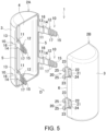
FIG. 5 is an exploded perspective view of the cover seen from the other divided cover side. -
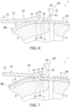
FIG. 6 is an explanatory diagram showing a state of a first locking part and a second locking part when the cover is removed. -
FIG. 7 is a cross-sectional view showing a modification of the cover. - Hereinafter, an embodiment of the present disclosure is described based on the drawings.
-
FIG. 1 is a perspective view showing an example of a cover.FIG. 2 is a side view of the cover.FIG. 3 is a cross-sectional view taken on line A-A inFIG. 2 . Acover 1 is of a cylindrical shape as a whole. Both axial ends of the cylindrical shape are closed. Thecover 1 is formed by joining a pair of dividedcovers - The divided covers 2A and 2B each have a two-layer structure including an
outer layer 3 and aninner layer 4. Theouter layer 3 is made of an elastomer. Theinner layer 4 is made of urethane foam. The elastomer has a hardness of, for example, 90 to 95 Shore A. Urethane foam is an example of a sound absorbing material formed from foamed resin of the present disclosure. However, at both axial ends of the cylindrical shape, there is noinner layer 4 and only theouter layer 3 is formed. - The
cover 1 is used to cover an object M indicated by a two-dot chain line inFIG. 3 in order to protect the object M and to prevent sound generated from the object M from escaping to the outside. The object M is, for example, a motor. While the object M is covered, theinner layer 4 elastically deforms and holds the object M. - As shown in
FIG. 4 andFIG. 5 as well, in theouter layer 3 of one dividedcover 2A, a pair offirst locking parts edges - In the
outer layer 3 of the other dividedcover 2B, a pair ofsecond locking parts edges cover 2A and bothedges 6 of the dividedcover 2B are abutted against each other, each first lockingpart 10 and each second lockingpart 20 face each other. By locking the facing first lockingpart 10 and second lockingpart 20 to each other, the divided covers 2A and 2B are joined. - The
first locking part 10 includes abase end piece 11, atip piece 12 and a lockinggroove 13. Thebase end piece 11 is of a strip shape protruding from theedge 5 of theouter layer 3 of the dividedcover 2A in an abutment direction with thesecond locking part 20. Thetip piece 12 is integrally formed at a protruding end of thebase end piece 11 and is of a strip shape protruding further than thebase end piece 11 in the abutment direction. Arrow D shown inFIG. 3 ,FIG. 4 , andFIG. 5 is the abutment direction. - The
tip piece 12 includes a lockingplate 14 and atip plate 15. The lockingplate 14 is connected to thebase end piece 11 and is of a plate shape protruding in the abutment direction D. In the lockingplate 14, a protrudingpiece 16 is formed protruding toward a side opposite to the abutment direction D. The protrudingpiece 16 is an example of a protruding portion of the present disclosure. - The locking
groove 13 is formed between thebase end piece 11 and the protrudingpiece 16. The lockinggroove 13 opens on the side opposite to the abutment direction D. - The
tip plate 15 is of a plate shape and connected to the lockingplate 14. However, as shown inFIG. 3 , thetip plate 15 is inclined outward at a predetermined angle with respect to the lockingplate 14 in a direction intersecting the abutment direction D. This inclination angle α is, for example, 12 °. The inclination angle α is not limited to 12 °, and can be set between 5 ° and 30 °. Thus, thetip plate 15 protrudes in an inclination direction away from theouter layer 3 toward the abutment direction D side. As shown inFIG. 3 , a protruding end of thetip piece 12 is spaced apart from an extended surface of theouter layer 3 by a distance L1 in a direction orthogonal to the abutment direction D. - A plurality of ridges each denoted by the numeral 17 are formed on both sides of the
tip plate 15 in a thickness direction. Theridges 17 extend in a width direction of thetip plate 15, and are formed at equal intervals in a direction in which thetip plate 15 protrudes. - The
second locking part 20 includes anotch 21, abridge 22, and aprotrusion 23. Thenotch 21 is formed by cutting out theedge 6 of theouter layer 3 of the dividedcover 2B toward the abutment direction D. - The
bridge 22 extends in a band shape along theedge 6 so as to straddle thenotch 21 outside theouter layer 3. Thus, aninsertion hole 24 that communicates with thenotch 21 and extends along theedge 6 is formed inside thebridge 22. A length of theinsertion hole 24 in a direction along theedge 6 is slightly larger than a width of thebase end piece 11 and thetip piece 12 of the first lockingpart 10. - The
protrusion 23 protrudes outward from an outer surface on both sides of thebridge 22 that sandwich thenotch 21. Ahead 25 protruding in the abutment direction D is formed at each protruding end of theprotrusion 23. - Here, as shown in
FIG. 3 , the protruding end of theprotrusion 23 is spaced apart from theouter layer 3 of the dividedcover 2B by a distance L2 in the direction orthogonal to the abutment direction D. The distance L2 to the tip of theprotrusion 23 is larger than the distance L1 being a separation distance of the protruding end of thetip piece 12 described above. - When the
cover 1 configured as above is used, first, half of the object M is covered with one of the divided covers 2A and 2B. In this state, while the other half of the object M is covered with the other of the divided covers 2A and 2B, each first lockingpart 10 and each second lockingpart 20 facing each other are locked. Specifically, with thetip piece 12 of the first lockingpart 10 inserted into theinsertion hole 24 of thesecond locking part 20, thebase end piece 11 is inserted until the protrudingpiece 16 passes through thebridge 22. After the protrudingpiece 16 passes through thebridge 22, thebridge 22 is elastically locked to the lockinggroove 13. Then, as shown inFIG. 1 to FIG. 3 , the first lockingpart 10 is prevented from coming off by thesecond locking part 20, the first lockingpart 10 and thesecond locking part 20 are locked to each other, and the object M is covered by the divided covers 2A and 2B. - In this way, since the
bridge 22 is elastically locked to the lockinggroove 13 and the first lockingpart 10 is prevented from coming off, the risk of accidental release of mutual locking due to an external impact or the like is reduced. In particular, since the protrudingpiece 16 is located outside thebridge 22, thebridge 22 is relatively unlikely to come off from the lockinggroove 13. - A gap S is formed between the divided covers 2A and 2B in the state in which the object M is covered. Thus, it is possible to pull out, from the gap S, a cable or the like connected to the object M.
- On the other hand, in the case of removing the
cover 1 from the object M, thetip plate 15 of thetip piece 12 of the first lockingpart 10 is grasped and is pulled so as to fall toward the dividedcover 2B side, as indicated by arrow a inFIG. 6 . Then, the lockinggroove 13 can be separated from thebridge 22, and the retainment can be released. At this time, as indicated by arrow b, theprotrusions second locking part 20 fall toward the dividedcover 2A side via theheads bridge 22 elastically moves toward the dividedcover 2A side together with theprotrusions bridge 22 can be easily separated from the lockinggroove 13. - After the locking
groove 13 is separated from thebridge 22, the lockingplate 14 is passed through theinsertion hole 24 from the inside of thebridge 22 together with the protrudingpiece 16 and is pulled out from thesecond locking part 20. Subsequently, thetip plate 15 is also passed through theinsertion hole 24 from the inside of thebridge 22 and is pulled out from thesecond locking part 20. If the locking between each first lockingpart 10 and each second lockingpart 20 is released in this way, the divided covers 2A and 2B can be removed from the object M. - In this way, the
cover 1 of the above embodiment includes: the divided covers 2A and 2B, made of an elastomer and respectively having a pair ofedges edges part 10, integrally formed on oneedge 5; and thesecond locking part 20, integrally formed on theother edge 6. By locking the first lockingpart 10 and thesecond locking part 20 to each other with the facingedges - The
first locking part 10 includes thebase end piece 11 protruding in the abutment direction D from theedge 5 to theedge 6 and thetip piece 12 protruding in the abutment direction D from the protruding end of thebase end piece 11. The lockinggroove 13 opening on the side opposite to the abutment direction D is formed between thebase end piece 11 and thetip piece 12. - The
second locking part 20 includes thenotch 21 formed in the abutment direction D from theedge 6, and thebridge 22 formed along theedge 6 so as to straddle thenotch 21 on the outer surface side of the dividedcover 2B. Theinsertion hole 24 communicating with thenotch 21 is formed inside thebridge 22. - By inserting the
tip piece 12 and thebase end piece 11 through theinsertion hole 24 and locking thebridge 22 to the lockinggroove 13, the first lockingpart 10 is locked to thesecond locking part 20 while being prevented from coming off. - According to this configuration, a simple structure is provided, and a state of covering the object M can be suitably maintained even if an elastomer is used as a material. Thus, the
cover 1 with high reliability can be provided. - The
tip piece 12 includes the lockingplate 14 connected to thebase end piece 11 and thetip plate 15 connected to the lockingplate 14. The lockingplate 14 includes, at an end opposite to the abutment direction D, the protrudingpiece 16 that forms the lockinggroove 13 between itself and thebase end piece 11. On the other hand, thetip plate 15 is connected to the lockingplate 14 while being inclined outward at the predetermined inclination angle α in the direction intersecting the abutment direction D. - Thus, by the protruding
piece 16, a locked state of thebridge 22 locked to the lockinggroove 13 can be suitably maintained. Since thetip plate 15 is inclined outward, locking and releasing operations of the first lockingpart 10 and thesecond locking part 20 are facilitated. - The inclination angle of the
tip plate 15 with respect to the lockingplate 14 is 5 ° to 30 °. - Thus, the
tip plate 15 does not excessively protrude from thecover 1, and an angle that facilitates the locking and releasing operations is formed. - The
ridge 17 is formed on both an outer surface and an inner surface of thetip plate 15. - Thus, the
ridge 17 serves as a non-slip when thetip plate 15 is grasped, and operation is facilitated. - The
bridge 22 is arranged in a position spaced outward from the outer surface of the dividedcover 2B. - Thus, the
tip piece 12 of the first lockingpart 10 is easily inserted into the inside of thebridge 22. - The
protrusion 23 protruding outward is provided on the outer surface of thebridge 22. - Thus, when the
cover 1 is removed, thebridge 22 can be elastically deformed in a direction away from the lockinggroove 13 using theprotrusion 23, and the locking and releasing operations of the first lockingpart 10 and thesecond locking part 20 are easily performed. - The distance L1 from the outer surface of the divided
cover 2A to the protruding end of thetip piece 12 in the direction intersecting the abutment direction D is less than the distance L2 from the outer surface of the dividedcover 2B to the tip of theprotrusion 23 in the direction intersecting the abutment direction D. - Thus, the
tip plate 15 is less likely to hinder an operation of theprotrusion 23. - The
inner layer 4 made of urethane foam is arranged on a portion of the inner surface of the divided covers 2A and 2B. - Thus, a sound insulation effect when covering the object M is enhanced.
- A modification of the present disclosure will be described below.
- In the above embodiment, the first locking part is provided on both edges of one divided cover, and the second locking part is provided on both edges of the other divided cover. However, the present disclosure is not limited thereto. For example, the first locking part may be provided on one edge of each divided cover and the second locking part may be provided on the other edge, and the first locking part and the second locking part facing each other may be locked.
- The number of locking parts provided on an edge is not limited to two, and may be three or more, or may be one.
- In the first locking part, the shape or number of ridges provided on the tip piece is not limited to the above embodiment. The ridge may not be provided on both front and back surfaces of the tip piece and may only be provided on either surface. The ridge may be omitted.
- In the above embodiment, the distance to the protruding end of the tip plate in the direction orthogonal to the abutment direction is less than the distance to the tip of the protrusion. However, these distances may be equal to each other.
- In the second locking part, the shape or number of protrusions is not limited to the above embodiment. The protrusion may be of a shape in which the upper ends are connected. The protrusion may be omitted.
- In the above embodiment, the cover body has a structure including a pair of divided covers. However, the cover body may include three or more divided covers. Conversely, there may be one cover body. That is, any structure may be used if it has a pair of edges facing each other and is joined by locking between the first locking part and the second locking part.
- The shape of the cover as a whole is not limited to a cylindrical shape, and can be changed as appropriate in accordance with the shape of the object.
- In the above embodiment, the inner layer made of urethane foam is formed inside each divided cover. However, as shown in
FIG. 7 , acovering layer 7 made of urethane foam may be formed on a portion of or the whole of a surface of theouter layer 3. - If the
covering layer 7 made of a sound insulating material is arranged on at least a portion of the outer surface of the divided covers 2A and 2B in this way, a relatively good sound insulation effect may be achieved. - The inner layer and/or the covering layer is not necessarily made of urethane foam, and may be made of other foamed resins.
- 1: cover; 2A, 2B: divided cover; 3: outer layer; 4: inner layer; 5, 6: edge; 7: covering layer; 10: first locking part; 11: base end piece; 12: tip piece; 13: locking groove; 14: locking plate; 15: tip plate; 16: protruding piece; 17: ridge; 20: second locking part; 21: notch; 22: bridge; 23: protrusion; 24: insertion hole; 25: head; M: object.
Claims (9)
- A cover, comprising:a cover body, made of an elastomer and having a pair of edges facing each other;a first locking part, integrally formed on one of the edges; anda second locking part, integrally formed on the other of the edges, whereinthe cover is able to cover an object by locking the first locking part and the second locking part to each other with the edges facing each other abutted against each other;the first locking part comprises a base end piece protruding in an abutment direction from the one of the edges to the other of the edges and a tip piece protruding in the abutment direction from a protruding end of the base end piece, and has a locking groove opening on a side opposite to the abutment direction formed between the base end piece and the tip piece;the second locking part comprises a notch formed in the abutment direction from the other of the edges, and a bridge formed along the other of the edges so as to straddle the notch on an outer surface side of the cover body, and an insertion hole communicating with the notch is formed inside the bridge; andby inserting the tip piece and the base end piece through the insertion hole and locking the bridge to the locking groove, the first locking part is locked to the second locking part while being prevented from coming off.
- The cover according to claim 1, whereinthe tip piece comprises a locking plate connected to the base end piece and a tip plate connected to the locking plate;the locking plate comprises, at an end opposite to the abutment direction, a protruding portion that forms the locking groove between itself and the base end piece; andthe tip plate is connected to the locking plate while being inclined outward at a predetermined inclination angle in a direction intersecting the abutment direction.
- The cover according to claim 2, wherein
the inclination angle of the tip plate with respect to the locking plate is 5 ° to 30 °. - The cover according to claim 3, wherein
a ridge is formed on at least one of an outer surface and an inner surface of the tip plate. - The cover according to claim 1, wherein
the bridge is arranged in a position spaced outward from the outer surface of the cover body. - The cover according to claim 1, wherein
a protrusion protruding outward is provided on an outer surface of the bridge. - The cover according to claim 6, wherein
a distance from the outer surface of the cover body to a protruding end of the tip piece in a direction intersecting the abutment direction is equal to or less than a distance from the outer surface of the cover body to a tip of the protrusion in the direction intersecting the abutment direction. - The cover according to claim 1, wherein
a sound absorbing material formed from foamed resin is arranged on at least a portion of an inner surface of the cover body. - The cover according to claim 8, wherein
the sound absorbing material is also arranged on at least a portion of the outer surface of the cover body.
Applications Claiming Priority (1)
| Application Number | Priority Date | Filing Date | Title |
|---|---|---|---|
| PCT/JP2022/048223 WO2024142264A1 (en) | 2022-12-27 | 2022-12-27 | Cover |
Publications (3)
| Publication Number | Publication Date |
|---|---|
| EP4421328A4 EP4421328A4 (en) | 2024-08-28 |
| EP4421328A1 true EP4421328A1 (en) | 2024-08-28 |
| EP4421328B1 EP4421328B1 (en) | 2025-12-17 |
Family
ID=91583786
Family Applications (1)
| Application Number | Title | Priority Date | Filing Date |
|---|---|---|---|
| EP22948186.6A Active EP4421328B1 (en) | 2022-12-27 | 2022-12-27 | Cover |
Country Status (5)
| Country | Link |
|---|---|
| US (1) | US20240212662A1 (en) |
| EP (1) | EP4421328B1 (en) |
| JP (1) | JPWO2024142264A1 (en) |
| CN (1) | CN118556162A (en) |
| WO (1) | WO2024142264A1 (en) |
Family Cites Families (17)
| Publication number | Priority date | Publication date | Assignee | Title |
|---|---|---|---|---|
| US3942750A (en) * | 1974-08-13 | 1976-03-09 | Thomas & Betts Corporation | Adjustable clamp |
| US4507828A (en) * | 1983-07-18 | 1985-04-02 | Japan Bano'k Co., Ltd. | Bundling belt device |
| JPH088391Y2 (en) * | 1989-08-31 | 1996-03-06 | 矢崎総業株式会社 | Case and cover locking structure |
| JPH0972976A (en) * | 1995-09-07 | 1997-03-18 | Seikosha Co Ltd | Coupling structure for case |
| CA2475571C (en) * | 2002-02-08 | 2008-01-08 | Dt Search & Design Llc | Cable retention device |
| US7661634B2 (en) * | 2002-02-08 | 2010-02-16 | Dt Search & Designs, Llc | Keyed channel strut mounted connector device |
| JP2003239920A (en) * | 2002-02-19 | 2003-08-27 | Seiko Epson Corp | Snap-fit joint structure and molded product |
| US8585623B2 (en) * | 2004-12-22 | 2013-11-19 | Ossur Hf | Orthopedic device |
| BRPI0504921B1 (en) * | 2005-11-04 | 2017-06-27 | Whirlpool S.A. | HERMETIC ACOUSTIC FLOOR PUMP COMPRESSOR |
| US8408356B2 (en) * | 2007-04-17 | 2013-04-02 | Fujitsu Limited | Storage box for electronic apparatus |
| US10961750B2 (en) * | 2017-09-29 | 2021-03-30 | Sumitomo Riko Company Limited | Cover unit |
| EP3531519B1 (en) * | 2018-02-27 | 2022-10-12 | Aptiv Technologies Limited | Electrical junction box |
| JP7083701B2 (en) * | 2018-06-07 | 2022-06-13 | 矢崎総業株式会社 | Lock structure, electrical junction box and wire harness |
| US11970313B2 (en) * | 2018-12-12 | 2024-04-30 | Yeti Coolers, Llc | Insulating container |
| WO2020126661A1 (en) | 2018-12-21 | 2020-06-25 | Adler Pelzer Holding Gmbh | Device for noise insulation of a machine |
| JP7297387B2 (en) * | 2019-06-19 | 2023-06-26 | 矢崎総業株式会社 | lock structure |
| JP7604315B2 (en) * | 2021-04-27 | 2024-12-23 | 株式会社イノアックコーポレーション | Soundproof cover |
-
2022
- 2022-12-27 WO PCT/JP2022/048223 patent/WO2024142264A1/en not_active Ceased
- 2022-12-27 JP JP2024510407A patent/JPWO2024142264A1/ja active Pending
- 2022-12-27 CN CN202280050324.9A patent/CN118556162A/en active Pending
- 2022-12-27 EP EP22948186.6A patent/EP4421328B1/en active Active
-
2023
- 2023-11-02 US US18/500,119 patent/US20240212662A1/en active Granted
Also Published As
| Publication number | Publication date |
|---|---|
| WO2024142264A1 (en) | 2024-07-04 |
| US20240212662A1 (en) | 2024-06-27 |
| JPWO2024142264A1 (en) | 2024-07-04 |
| CN118556162A (en) | 2024-08-27 |
| EP4421328B1 (en) | 2025-12-17 |
Similar Documents
| Publication | Publication Date | Title |
|---|---|---|
| JP4258529B2 (en) | Wire harness protector | |
| US8704099B2 (en) | Grommet with silencer | |
| US20170085067A1 (en) | Wire cover | |
| EP0672010B1 (en) | Buttonhead tie with split centering pilot | |
| US9412494B2 (en) | Electrical-wire-protecting member | |
| JP2009131055A (en) | Wire harness exterior parts and wire harness assemblies | |
| US20080257600A1 (en) | Wire Harness Leading-Out Port Structure of Electric Connection Box | |
| EP4421328B1 (en) | Cover | |
| US7100237B2 (en) | Grommet | |
| JP7154825B2 (en) | cover unit | |
| CN103221263A (en) | Electric wire fixing device | |
| EP3796477B1 (en) | Electric wire cover | |
| JP7234893B2 (en) | Cushion seat and wire harness | |
| JP7279527B2 (en) | Wiring material | |
| JP5405989B2 (en) | Antenna component and antenna device | |
| JP7646958B1 (en) | cover | |
| US12434887B1 (en) | Cover | |
| JP2001258138A (en) | Vehicle body fixing structure of clamp | |
| JP5807563B2 (en) | Band lock structure and harness clamp | |
| JP2021150996A (en) | Protector | |
| US20250202208A1 (en) | Wire harness | |
| JP5872823B2 (en) | Protector | |
| WO2018096950A1 (en) | Wrapping tool | |
| JP5488259B2 (en) | Band type corrugated clamp | |
| JP2018160983A (en) | Binding structure of wiring member |
Legal Events
| Date | Code | Title | Description |
|---|---|---|---|
| STAA | Information on the status of an ep patent application or granted ep patent |
Free format text: STATUS: UNKNOWN |
|
| STAA | Information on the status of an ep patent application or granted ep patent |
Free format text: STATUS: THE INTERNATIONAL PUBLICATION HAS BEEN MADE |
|
| PUAI | Public reference made under article 153(3) epc to a published international application that has entered the european phase |
Free format text: ORIGINAL CODE: 0009012 |
|
| STAA | Information on the status of an ep patent application or granted ep patent |
Free format text: STATUS: REQUEST FOR EXAMINATION WAS MADE |
|
| 17P | Request for examination filed |
Effective date: 20240102 |
|
| A4 | Supplementary search report drawn up and despatched |
Effective date: 20240708 |
|
| AK | Designated contracting states |
Kind code of ref document: A1 Designated state(s): AL AT BE BG CH CY CZ DE DK EE ES FI FR GB GR HR HU IE IS IT LI LT LU LV MC ME MK MT NL NO PL PT RO RS SE SI SK SM TR |
|
| GRAP | Despatch of communication of intention to grant a patent |
Free format text: ORIGINAL CODE: EPIDOSNIGR1 |
|
| STAA | Information on the status of an ep patent application or granted ep patent |
Free format text: STATUS: GRANT OF PATENT IS INTENDED |
|
| DAV | Request for validation of the european patent (deleted) | ||
| DAX | Request for extension of the european patent (deleted) | ||
| INTG | Intention to grant announced |
Effective date: 20250805 |
|
| GRAS | Grant fee paid |
Free format text: ORIGINAL CODE: EPIDOSNIGR3 |
|
| GRAA | (expected) grant |
Free format text: ORIGINAL CODE: 0009210 |
|
| STAA | Information on the status of an ep patent application or granted ep patent |
Free format text: STATUS: THE PATENT HAS BEEN GRANTED |
|
| AK | Designated contracting states |
Kind code of ref document: B1 Designated state(s): AL AT BE BG CH CY CZ DE DK EE ES FI FR GB GR HR HU IE IS IT LI LT LU LV MC ME MK MT NL NO PL PT RO RS SE SI SK SM TR |
|
| REG | Reference to a national code |
Ref country code: CH Ref legal event code: F10 Free format text: ST27 STATUS EVENT CODE: U-0-0-F10-F00 (AS PROVIDED BY THE NATIONAL OFFICE) Effective date: 20251217 Ref country code: GB Ref legal event code: FG4D |
|
| REG | Reference to a national code |
Ref country code: DE Ref legal event code: R096 Ref document number: 602022027239 Country of ref document: DE |
|
| PGFP | Annual fee paid to national office [announced via postgrant information from national office to epo] |
Ref country code: AT Payment date: 20260113 Year of fee payment: 4 |
|
| REG | Reference to a national code |
Ref country code: DE Ref legal event code: R084 Ref document number: 602022027239 Country of ref document: DE |
|
| REG | Reference to a national code |
Ref country code: LT Ref legal event code: MG9D |
|
| PG25 | Lapsed in a contracting state [announced via postgrant information from national office to epo] |
Ref country code: NO Free format text: LAPSE BECAUSE OF FAILURE TO SUBMIT A TRANSLATION OF THE DESCRIPTION OR TO PAY THE FEE WITHIN THE PRESCRIBED TIME-LIMIT Effective date: 20260317 |
|
| PGFP | Annual fee paid to national office [announced via postgrant information from national office to epo] |
Ref country code: DE Payment date: 20260121 Year of fee payment: 4 |
|
| PG25 | Lapsed in a contracting state [announced via postgrant information from national office to epo] |
Ref country code: FI Free format text: LAPSE BECAUSE OF FAILURE TO SUBMIT A TRANSLATION OF THE DESCRIPTION OR TO PAY THE FEE WITHIN THE PRESCRIBED TIME-LIMIT Effective date: 20251217 Ref country code: HR Free format text: LAPSE BECAUSE OF FAILURE TO SUBMIT A TRANSLATION OF THE DESCRIPTION OR TO PAY THE FEE WITHIN THE PRESCRIBED TIME-LIMIT Effective date: 20251217 |
|
| PG25 | Lapsed in a contracting state [announced via postgrant information from national office to epo] |
Ref country code: RS Free format text: LAPSE BECAUSE OF FAILURE TO SUBMIT A TRANSLATION OF THE DESCRIPTION OR TO PAY THE FEE WITHIN THE PRESCRIBED TIME-LIMIT Effective date: 20260317 |
|
| REG | Reference to a national code |
Ref country code: NL Ref legal event code: MP Effective date: 20251217 |
|
| PG25 | Lapsed in a contracting state [announced via postgrant information from national office to epo] |
Ref country code: LV Free format text: LAPSE BECAUSE OF FAILURE TO SUBMIT A TRANSLATION OF THE DESCRIPTION OR TO PAY THE FEE WITHIN THE PRESCRIBED TIME-LIMIT Effective date: 20251217 |
|
| PG25 | Lapsed in a contracting state [announced via postgrant information from national office to epo] |
Ref country code: BG Free format text: LAPSE BECAUSE OF FAILURE TO SUBMIT A TRANSLATION OF THE DESCRIPTION OR TO PAY THE FEE WITHIN THE PRESCRIBED TIME-LIMIT Effective date: 20251217 |