EP4421324A1 - Electric compressor - Google Patents
Electric compressor Download PDFInfo
- Publication number
- EP4421324A1 EP4421324A1 EP22895350.1A EP22895350A EP4421324A1 EP 4421324 A1 EP4421324 A1 EP 4421324A1 EP 22895350 A EP22895350 A EP 22895350A EP 4421324 A1 EP4421324 A1 EP 4421324A1
- Authority
- EP
- European Patent Office
- Prior art keywords
- terminal
- hermetic
- linking
- pins
- bus bar
- Prior art date
- Legal status (The legal status is an assumption and is not a legal conclusion. Google has not performed a legal analysis and makes no representation as to the accuracy of the status listed.)
- Granted
Links
Images




Classifications
-
- H—ELECTRICITY
- H02—GENERATION; CONVERSION OR DISTRIBUTION OF ELECTRIC POWER
- H02K—DYNAMO-ELECTRIC MACHINES
- H02K5/00—Casings; Enclosures; Supports
- H02K5/04—Casings or enclosures characterised by the shape, form or construction thereof
- H02K5/22—Auxiliary parts of casings not covered by groups H02K5/06-H02K5/20, e.g. shaped to form connection boxes or terminal boxes
-
- F—MECHANICAL ENGINEERING; LIGHTING; HEATING; WEAPONS; BLASTING
- F04—POSITIVE - DISPLACEMENT MACHINES FOR LIQUIDS; PUMPS FOR LIQUIDS OR ELASTIC FLUIDS
- F04B—POSITIVE-DISPLACEMENT MACHINES FOR LIQUIDS; PUMPS
- F04B35/00—Piston pumps specially adapted for elastic fluids and characterised by the driving means to their working members, or by combination with, or adaptation to, specific driving engines or motors, not otherwise provided for
- F04B35/04—Piston pumps specially adapted for elastic fluids and characterised by the driving means to their working members, or by combination with, or adaptation to, specific driving engines or motors, not otherwise provided for the means being electric
-
- F—MECHANICAL ENGINEERING; LIGHTING; HEATING; WEAPONS; BLASTING
- F04—POSITIVE - DISPLACEMENT MACHINES FOR LIQUIDS; PUMPS FOR LIQUIDS OR ELASTIC FLUIDS
- F04B—POSITIVE-DISPLACEMENT MACHINES FOR LIQUIDS; PUMPS
- F04B39/00—Component parts, details, or accessories, of pumps or pumping systems specially adapted for elastic fluids, not otherwise provided for in, or of interest apart from, groups F04B25/00 - F04B37/00
- F04B39/12—Casings; Cylinders; Cylinder heads; Fluid connections
- F04B39/121—Casings
-
- F—MECHANICAL ENGINEERING; LIGHTING; HEATING; WEAPONS; BLASTING
- F04—POSITIVE - DISPLACEMENT MACHINES FOR LIQUIDS; PUMPS FOR LIQUIDS OR ELASTIC FLUIDS
- F04C—ROTARY-PISTON, OR OSCILLATING-PISTON, POSITIVE-DISPLACEMENT MACHINES FOR LIQUIDS; ROTARY-PISTON, OR OSCILLATING-PISTON, POSITIVE-DISPLACEMENT PUMPS
- F04C18/00—Rotary-piston pumps specially adapted for elastic fluids
- F04C18/02—Rotary-piston pumps specially adapted for elastic fluids of arcuate-engagement type, i.e. with circular translatory movement of co-operating members, each member having the same number of teeth or tooth-equivalents
- F04C18/0207—Rotary-piston pumps specially adapted for elastic fluids of arcuate-engagement type, i.e. with circular translatory movement of co-operating members, each member having the same number of teeth or tooth-equivalents both members having co-operating elements in spiral form
- F04C18/0215—Rotary-piston pumps specially adapted for elastic fluids of arcuate-engagement type, i.e. with circular translatory movement of co-operating members, each member having the same number of teeth or tooth-equivalents both members having co-operating elements in spiral form where only one member is moving
-
- F—MECHANICAL ENGINEERING; LIGHTING; HEATING; WEAPONS; BLASTING
- F04—POSITIVE - DISPLACEMENT MACHINES FOR LIQUIDS; PUMPS FOR LIQUIDS OR ELASTIC FLUIDS
- F04C—ROTARY-PISTON, OR OSCILLATING-PISTON, POSITIVE-DISPLACEMENT MACHINES FOR LIQUIDS; ROTARY-PISTON, OR OSCILLATING-PISTON, POSITIVE-DISPLACEMENT PUMPS
- F04C23/00—Combinations of two or more pumps, each being of rotary-piston or oscillating-piston type, specially adapted for elastic fluids; Pumping installations specially adapted for elastic fluids; Multi-stage pumps specially adapted for elastic fluids
- F04C23/008—Hermetic pumps
-
- H—ELECTRICITY
- H02—GENERATION; CONVERSION OR DISTRIBUTION OF ELECTRIC POWER
- H02K—DYNAMO-ELECTRIC MACHINES
- H02K5/00—Casings; Enclosures; Supports
- H02K5/04—Casings or enclosures characterised by the shape, form or construction thereof
- H02K5/22—Auxiliary parts of casings not covered by groups H02K5/06-H02K5/20, e.g. shaped to form connection boxes or terminal boxes
- H02K5/225—Terminal boxes or connection arrangements
-
- F—MECHANICAL ENGINEERING; LIGHTING; HEATING; WEAPONS; BLASTING
- F04—POSITIVE - DISPLACEMENT MACHINES FOR LIQUIDS; PUMPS FOR LIQUIDS OR ELASTIC FLUIDS
- F04C—ROTARY-PISTON, OR OSCILLATING-PISTON, POSITIVE-DISPLACEMENT MACHINES FOR LIQUIDS; ROTARY-PISTON, OR OSCILLATING-PISTON, POSITIVE-DISPLACEMENT PUMPS
- F04C2240/00—Components
- F04C2240/80—Other components
- F04C2240/803—Electric connectors or cables; Fittings therefor
Definitions
- the present disclosure relates to an electric compressor.
- a hermetic terminal has been known as means for energizing the inside of a housing that requires airtightness, such as a compressor. Such a hermetic terminal supplies power from the outside to the inside of the housing via a connecting portion to which the external cable and the hermetic terminal are connected.
- the compressor tends to be smaller and have a larger capacity, and accordingly, a current flowing through a cable or a connection terminal that supplies power from the outside is increasing.
- the cable is made thicker in order to deal with an increase in current, the hermetic terminal unit becomes large.
- the size of the hermetic terminal unit is increased, the size of the insertion hole for the hermetic terminal formed in the housing is increased, such that reinforcement for ensuring pressure resistance or the like is required.
- one hermetic terminal is connected to the plurality of external cables, such that the number of external cables is greater than the number of hermetic terminals. For this reason, the number of connection points of the external cables at a connection destination increases, and the work in a case of installation becomes complicated.
- the present disclosure has been made in view of such circumstances, and an object of the present disclosure is to provide an electric compressor capable of dealing with the increase in current without increasing the number of external cables.
- an electric compressor including: an electric motor; a compression mechanism that is driven by the electric motor to compress a refrigerant; a housing that accommodates the electric motor and the compression mechanism in a sealed space; a plurality of hermetic terminals that are respectively inserted into a plurality of through-holes formed in the housing and that are sealed not to communicate the sealed space with an outer space; and a connection mechanism that is fixed to the housing and that electrically connects the hermetic terminals to a plurality of external cables.
- Each hermetic terminal has an insulation part which is formed of an insulation material, a plurality of pins each of which is conductive and is inserted into the insulation part such that one end and the other end thereof protrude, and a plurality of straps each of which is fixed to each one end of the plurality of pins
- the connection mechanism has a plurality of bus bars each of which is conductive and is connected to each one of the external cables, a terminal block to which the plurality of bus bars are fixed and which is installed in the housing, and a plurality of linking cables each of which is connected to each one of the plurality of straps.
- the plurality of linking cables are respectively connected to the plurality of bus bars.
- the compressor (electric compressor) 1 is used in an air conditioner and performs two-stage compression of a refrigerant R which is gas such as carbon dioxide.
- the compressor 1 is fixed to an installation surface FL via a leg portion 3.
- the compressor 1 includes a housing 11, a rotary compression mechanism (low-stage compression mechanism) 12 provided inside the housing 11, a scroll compression mechanism (high-stage compression mechanism) 13, an electric motor 14, and a rotary shaft (rotary shaft portion) 15.
- the housing 11 includes a body 21 extending in a cylindrical shape along the axis X, and an upper cover portion 22 and a lower cover portion 23 that close upper and lower openings of the body 21.
- the inside of the housing 11 accommodates each part of the compressor 1 including the electric motor 14, the rotary compression mechanism 12, and the scroll compression mechanism 13.
- the inside of the housing 11 forms a sealed space.
- the rotary shaft 15 is provided to extend vertically along an axis X inside the housing 11.
- the upper end (one end) side of the rotary shaft 15 is rotatably supported by an upper bearing 31.
- the lower end (the other end) side of the rotary shaft 15 is rotatably supported by a lower bearing 32.
- the electric motor 14 is disposed at the center of the rotary shaft 15 in the longitudinal direction and on the outer peripheral side of the rotary shaft 15, and rotates the rotary shaft 15 around the axis X.
- the electric motor 14 faces a rotor 38 fixed to the outer peripheral surface of the rotary shaft 15 in the radial direction with a gap interposed between the rotor 38 and the outer peripheral surface of the rotor 38, and has a stator 39 which is fixed by being shrink-fitted to the inner wall of the body 21 of the housing 11 and so on.
- the rotary compression mechanism 12 is driven by the electric motor 14 to compress the refrigerant R.
- the scroll compression mechanism 13 is driven by the electric motor and further compresses the refrigerant R compressed by the rotary compression mechanism 12.
- the rotor 38 is provided with rotor passages 38a which are provided with predetermined intervals in the circumferential direction. Each rotor passage 38a penetrates the rotor 38 in the vertical direction (axis X direction).
- the refrigerant R which are discharged from the rotary compression mechanism 12, flows upward through the rotor passages 38a.
- An oil separation plate 38b is fixed to an upper portion of the rotor 38.
- the oil separation plate 38b has a disk shape and is disposed to extend in the horizontal direction. The oil separation plate 38b rotates around the axis X together with the rotor 38.
- a plurality of stator passages 39a are formed on the outer periphery of the stator 39 with predetermined angular intervals in the circumferential direction. As shown in Fig. 1 , an upper coil end 39b, in which the winding is folded, is located in an upper portion of the stator 39, and a lower coil end 39c, in which the winding is folded, is located in a lower portion of the stator 39.
- the electric motor 14 is connected to a power source via an inverter (not shown in the drawing), and rotates the rotary shaft 15 with a variable frequency.
- the rotary compression mechanism 12 is provided inside the housing 11 on the lower end (the other end) side of the rotary shaft 15.
- the rotary compression mechanism 12 is a two-cylinder mechanism in the present embodiment, and includes an eccentric shaft portion 41 which is provided on the rotary shaft 15, a rotor 42 which is fixed to the eccentric shaft portion 41 and is eccentric with respect to the axis X as the rotary shaft 15 rotates to rotate in a compression chamber C1, and a cylinder 44 in which the compression chamber C1 is formed.
- the refrigerant R is supplied from a suction pipe 33 to the compression chamber C1 formed in the cylinder 44.
- the refrigerant compressed in the compression chamber C1 is discharged from a rotary discharge pipe 43 to a region below the electric motor 14 in the housing 11 via the lower bearing 32.
- the cylinder 44 is fixed to the lower bearing 32 from the lower side by a bolt 48.
- An oil pump 49 which is fixed by the bolt 48 together with the cylinder 44, is provided below the cylinder 44. Oil is sucked from an oil reservoir O1 at the lower portion of the housing 11 by the oil pump 49, passes through an oil supply hole 15a penetrated along the axis X of the rotary shaft 15, and is guided toward the upper bearing 31.
- the scroll compression mechanism 13 is disposed inside the housing 11 above the electric motor 14.
- the scroll compression mechanism 13 includes a fixed scroll 51 fixed to the upper bearing 31, and an orbiting scroll 57 disposed below the fixed scroll 51 to face the fixed scroll 51.
- the fixed scroll 51 has an end plate 52 fixed to an upper surface of the upper bearing 31, and a fixed wrap 53 protruding downward from the end plate 52.
- a discharge hole 52a penetrating upward and downward is formed in a central portion (in the vicinity of the axis X) of the end plate 52.
- the orbiting scroll 57 is disposed to be interposed between the upper bearing 31 and the fixed scroll 51.
- the orbiting scroll 57 has an end plate 58 connected to the upper end side of the rotary shaft 15, and an orbiting wrap 59 protruding upward from the end plate 58.
- the orbiting scroll 57 revolves around the axis X with respect to the fixed scroll 51.
- the end plate 58 is fixed to an eccentric shaft portion 56 provided at the upper end of the rotary shaft 15 via a bush 55, and rotates eccentrically with respect to the axis X as the rotary shaft 15 rotates.
- the orbiting wrap 59 meshes with the fixed wrap 53 to form a compression chamber C2 for compressing the refrigerant R between the orbiting wrap 59 and the fixed wrap 53.
- a balance weight chamber 63 is formed between a recessed portion on the central side of the upper bearing 31 and the lower portion of the orbiting scroll 57. In the balance weight chamber 63, the balance weight 54 rotates together with the rotary shaft 15.
- the refrigerant R which is compressed by the rotary compression mechanism 12 and discharged into the housing 11, is sucked into the compression chamber C2 from the outer peripheral side of the scroll compression mechanism 13 and is compressed toward the central side.
- the compressed refrigerant R is discharged from a discharge pipe 34 to the outside of the housing 11 via the discharge hole 52a of the fixed scroll 51.
- a cover 45 is provided below the upper bearing 31 to cover the upper bearing 31.
- the cover 45 is formed by sheet metal processing, and has a substantially conical shape of which a diameter is increased from the lower side to the upper side.
- a suction opening 45a is provided at the lower end of the cover 45. That is, the suction opening 45a faces downward and is an annular region formed between the cover 45 and the rotary shaft 15.
- the space below the housing 11 and the space on the upper bearing 31 side are partitioned by the cover 45, and only the refrigerant, which is sucked from the suction opening 45a, is guided to the scroll compression mechanism 13.
- An oil level tank 60 is provided outside and below the housing 11.
- the oil level tank 60 is regarded as a hollow container and communicates with the inside of the housing 11 via a lower pipe 61 and an upper pressure equalization pipe 62.
- the oil level tank 60 measures the oil level of the oil reservoir O1 by guiding the oil from the oil reservoir O1 in the housing 11 via the lower pipe 61.
- a downstream end of the oil separator oil return pipe 65 is connected to a lower side portion of the housing 11.
- An upstream end of the oil separator oil return pipe 65 is connected to an oil separator (not shown in the drawing).
- the oil which is separated from the refrigerant discharged from the compressor 1 by the oil separator, is returned to the oil reservoir O1 in the housing 11 via the oil separator oil return pipe 65.
- a height position, at which the downstream end of the oil separator oil return pipe 65 is connected to the housing 11, is set below the lower bearing 32.
- An oil return pipe 67 which extends in the vertical direction while coming into contact with the inner wall of the housing 11, is provided inside the housing 11.
- the oil return pipe 67 is provided such that an upper end (one end) thereof is fixed to the upper bearing 31 and a lower end (the other end) thereof is positioned at the oil reservoir O1 in the lower portion of the housing 11.
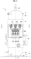
- Fig. 2 is a left side view of the compressor 1 shown in Fig. 1 .
- Fig. 3 is a partially enlarged view of a connection mechanism 200 shown in Fig. 2 .
- Fig. 5 is a cross-sectional view taken along the line A-A of the compressor 1 shown in Fig. 2 .
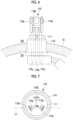
- Fig. 6 is a partially enlarged view of the hermetic terminal 120 shown in Fig. 5 .
- Fig. 7 is a plan view of the hermetic terminal 120 shown in Fig. 6 as viewed from above.
- the compressor 1 includes the three hermetic terminals 110, 120, and 130, and the connection mechanism 200.
- three through-holes 21A, 21B, and 21C are formed in the body 21 of the housing 11.
- the hermetic terminal 110 is inserted into the through-hole 21A
- the hermetic terminal 120 is inserted into the through-hole 21B
- the hermetic terminal 130 is inserted into the through-hole 21C.
- the hermetic terminals 110, 120, and 130 are respectively joined to the through-holes 21A, 21B, and 21C through welding.
- the hermetic terminals 110, 120, and 130 are sealed such that a sealed space CS and an outer space OS do not communicate with each other.
- the details of the structure of the hermetic terminal 110 will be described with reference to Figs. 6 and 7 . Since the structures of the hermetic terminals 120 and 130 are the same as the structures of the hermetic terminals 110, the following description will not be given.
- the hermetic terminal 110 has an insulation part 111, three pins 112a, 112b, and 112c, three straps 113a, 113b, and 113c, and a casing 114.
- the insulation part 111 is formed of an insulation material and is a member that holds the three pins 112a, 112b, and 112c in an insulated state in which the three pins 112a, 112b, and 112c do not conduct with each other.
- the insulation part 111 is fixed to the casing 114.
- the three pins 112a, 112b, and 112c are conductive members each of which is inserted into the insulation part 111 such that one end thereof on the outer space OS side and the other end thereof on the sealed space CS side protrude.
- the three pins 112a, 112b, and 112c are respectively formed to extend in the same direction (the vertical direction in Fig. 6 ).
- Fig. 7 at a position at which the straight line L1 connecting a position (first disposition position) where the pin (first pin) 112a is disposed and a position (second disposition position) where the pin (second pin) 112c is disposed does not pass, on a plane orthogonal to a direction (predetermined direction) where the three pins 112a, 112b, and 112c extend, the pin (the other pin) 112b is disposed.
- the three straps 113a, 113b, and 113c are conductive members and are each fixed to one end of each of the three pins 112a, 112b, and 112c on the outer space OS side.
- Each one of linking cables 251, 252, and 253 shown in Fig. 3 is electrically connected to each of the three straps 113a, 113b, and 113c via each of crimping terminals 251b, 252b, and 253b.
- Each one of the linking cables 254, 255, and 256 shown in Fig. 3 is electrically connected to each of the three straps (not shown in the drawing) of the hermetic terminal 120.
- Each one of the linking cables 257, 258, and 259 shown in Fig. 3 is electrically connected to each of the three straps (not shown in the drawing) included in the hermetic terminal 130.
- connection mechanism 200 is a mechanism that is fixed to the body 21 of the housing 11 and electrically connects the hermetic terminals 110, 120, and 130 to the U-phase cable 310, the V-phase cable 320, and the W-phase cable 330.
- connection mechanism 200 has three bus bars 210, 220, and 230, a terminal block 240, and nine linking cables 251, 252, 253, 254, 255, 256, 257, 258, and 259.
- Each of the three bus bars 210, 220, and 230 is a member formed of a conductive metallic material.
- One U-phase cable (external cable) 310 is electrically connected to the bus bar 210 via the crimping terminal 311.
- One V-phase cable (external cable) 320 is electrically connected to the bus bar 220 via the crimping terminal 321.
- One W-phase cable (external cable) 330 is electrically connected to the bus bar 230 via the crimping terminal 331.
- the terminal block 240 is a structure to which the bus bars 210, 220, and 230 are fixed and in which the body 21 of the housing 11 is installed.
- the terminal block 240 is installed in the body 21 such that the bus bars 210, 220, and 230 maintain the insulated state with respect to the body 21 of the housing 11.
- the three linking cables 251, 254, and 257 which are respectively connected to the hermetic terminals 110, 120, and 130, are connected to the bus bar 210 via crimping terminals 251a, 254a, and 257a.
- the three linking cables 253, 256, and 259, which are respectively connected to the hermetic terminal 110, 120, and 130, are connected to the bus bar 230 via crimping terminals 253a, 256a, and 259a.
- the three linking cables 251, 254, and 257 are connected to the bus bar 210.
- the linking cable (the other linking cable) 254 is connected to the bus bar 210 at the position of the crimping terminal 254a.
- three linking cables are respectively connected to the bus bars 210, 220, and 230 but other aspects may be used.
- the hermetic terminals 110, 120, and 130 each include an optional number of pins of 3 or more, and an optional number of linking cables of 3 or more are connected to each of the bus bars 210, 220, and 230.
- the U-phase cable 310, the V-phase cable 320, and the W-phase cable 330 each are connected to a UVW output terminal of a control unit (not shown in the drawing) that outputs a three-phase AC current applied to the electric motor 14.
- the U-phase cable 310 transmits a U-phase current via the bus bar 210 to the hermetic terminals 110, 120, and 130 via the linking cables 251, 254, and 257.
- the V-phase cable 320 transmits a V-phase current via the bus bar 220 to the hermetic terminals 110, 120, and 130 via the linking cables 252, 255, and 258.
- the W-phase cable 330 transmits a W-phase current via the bus bar 230 to the hermetic terminals 110, 120, and 130 via the linking cables 253, 256, and 259.
- the electric motor 14 of the present embodiment is a three-phase AC motor that has a U terminal, a V terminal, and a W terminal.
- the three pins 112a, 112b, and 112c of the hermetic terminal 110, which is inserted into the through-hole 21A, are respectively connected to the U terminal, the V terminal, and the W terminal of the electric motor 14.
- the three pins of the hermetic terminal 120, which is inserted into the through-hole 21B, are respectively connected to the U terminal, the V terminal, and the W terminal of the electric motor 14.
- the three pins of the hermetic terminal 130, which is inserted into the through-hole 21C, are respectively connected to the U terminal, the V terminal, and the W terminal of the electric motor 14.
- the three straps 113a, 113b, and 113c, which are fixed to the hermetic terminal 110, are connected to the bus bar 210 through the three linking cables 251, 254, and 257.
- the three straps, which are fixed to the hermetic terminal 120, are connected to the bus bar 220 through the three linking cables 252, 255, and 258.
- the three straps, which are fixed to the hermetic terminal 130, are connected to the bus bar 230 through the three linking cables 253, 256, and 259.
- the connection mechanism 200 has a covering member 260.
- the covering member 260 protects the three bus bars 210, 220, and 230, the terminal block 240, and the nine linking cables 251, 252, 253, 254, 255, 256, 257, 258, and 259 such that those are not exposed to the outside.
- Figs. 2 and 3 show a state in which the covering member 260 is removed from the connection mechanism 200.
- the plurality of through-holes 21A, 21B, and 21C are formed in the body 21 of the housing 11 that accommodates the electric motor 14, the rotary compression mechanism 12, and the scroll compression mechanism 13 in the sealed space CS.
- the plurality of hermetic terminals 110, 120, and 130 are respectively inserted into the plurality of through-holes 21A, 21B, and 21C.
- Each of the plurality of straps 113a, 113b, and 113c is fixed to one end of each of the plurality of pins 112a, 112b, and 112c of the hermetic terminal 110, and each one of the linking cables 251, 254, and 257 is connected to each of the plurality of straps 113a, 113b, and 113c.
- the connection mechanism 200 which electrically connects the hermetic terminals 110, 120, and 130 to the U-phase cable 310, the V-phase cable 320, and the W-phase cable 330, is fixed to the body 21 of the housing 11.
- the connection mechanism 200 has the plurality of bus bars 210, 220, and 230 which are conductive and the terminal block 240 which fixes the plurality of bus bars 210, 220, and 230.
- each one of the linking cables 251, 254, and 257 is connected to each of the plurality of straps 113a, 113b, and 113c, the plurality of linking cables 251, 254, and 257 are connected to the bus bar 210, the plurality of linking cables 252, 255, and 258 are connected to the bus bar 220, and the plurality of linking cables 253, 256, and 259 are connected to the bus bar 230.
- the plurality of linking cables 251, 254, and 257 are combined into one bus bar 210 and then connected to the U-phase cable 310.
- the plurality of linking cables 252, 255, and 258 are combined into one bus bar 220 and then connected to the V-phase cable 320.
- the plurality of linking cables 253, 256, and 259 are combined into one bus bar 230 and then connected to the W-phase cable 330. Therefore, as compared with a case where each of the plurality of straps is directly connected to the external cable, it is possible to deal with an increase in current without increasing the number of the external cables.
- the U terminal, the V terminal, and the W terminal of the electric motor 14 are respectively connected to the plurality of pins 112a, 112b, and 112c of the hermetic terminal 110 inserted into the through-hole 21A.
- the U terminal, the V terminal, and the W terminal of the electric motor 14 are respectively connected to the plurality of pins of the hermetic terminal 120 inserted into the through-hole 21B.
- the U terminal, the V terminal, and the W terminal of the electric motor 14 are respectively connected to the plurality of pins of the hermetic terminal 130 inserted into the through-hole 21C.
- the combinations of the terminals of the electric motor 14 connected to the respective hermetic terminals 110, 120, and 130 are the same. Therefore, it is possible to suppress occurrence of work errors in which there are errors in combinations of the wiring connecting the pins of the respective hermetic terminals and the respective terminals of the electric motor.
- the other pin 112b is not disposed on the same straight line. Therefore, as compared with a case where all of the first pin 112a, the second pin 112c, and the other pin 112b are arranged on the same straight line, the installation intervals of the pins 112a, 112b, and 112c in the linear direction are shortened, and the installation areas of the plurality of pins 112a, 112b, and 112c can be reduced.
- the other linking cable 254 (256) is not connected.
- the installation areas of the crimping terminals 251a, 254a, and 257a (253a, 256a, 259a) of the plurality of linking cables 251, 254, and 257 (253, 256, 259) can be reduced by shortening the interval between the connection positions of the linking cables in the linear direction.
- Fig. 8 is a partially enlarged view of the connection mechanism 200 according to the second embodiment of the present disclosure.
- the present embodiment is a modification example of the first embodiment and is assumed to be the same as the first embodiment except for a case particularly described below, and the same description will not be given below.
- the three pins 112a, 112b, and 112c of the hermetic terminal 110 which is inserted into the through-hole 21A, are respectively connected to the U terminal, the V terminal, and the W terminal of the electric motor 14.
- the three pins of the hermetic terminal 120 which is inserted into the through-hole 21B, are respectively connected to the U terminal, the V terminal, and the W terminal of the electric motor 14.
- the three pins of the hermetic terminal 130, which is inserted into the through-hole 21C, are respectively connected to the U terminal, the V terminal, and the W terminal of the electric motor 14.
- the three pins 112a, 112b, and 112c of the hermetic terminal 110 which is inserted into the through-hole 21A, are connected to the U terminal of the electric motor 14.
- the three pins of the hermetic terminal 120 which is inserted into the through-hole 21B, are connected to the V terminal of the electric motor 14.
- the three pins of the hermetic terminal 130 which is inserted into the through-hole 21C, are connected to the W terminal of the electric motor 14.
- the three linking cables 251, 252, and 253, each of which is connected to the hermetic terminal 110, are connected to the bus bar 210 via crimping terminals 251a, 252a, and 253a.
- the three linking cables 254, 255, and 256, each of which is connected to the hermetic terminal 120, are connected to the bus bar 220 via the crimping terminals.
- the three linking cables 257, 258, and 259, each of which is connected to the hermetic terminal 130, are connected to the bus bar 230 via the crimping terminals 257a, 258a, and 259a.
- each of the three straps 113a, 113b, and 113c which are fixed to the hermetic terminal 110, is connected to the bus bar 210 through each of the three linking cables 251, 252, and 253.
- Each of the three straps, which are fixed to the hermetic terminal 120, is connected to the bus bar 220 through each of the three linking cables 254, 255, and 256.
- Each of the three straps, which are fixed to the hermetic terminal 130, is connected to the bus bar 230 through each of the three linking cables 257, 258, and 259.
- each one of the linking cables 251, 252, 253 is connected to each of the plurality of straps 113a, 113b, and 113c, and the plurality of linking cables 251, 252, 253 are connected to the bus bar 210, the plurality of linking cables 254, 255, and 256 are connected to the bus bar 220, and the plurality of linking cables 257, 258, and 259 are connected to the bus bar 230.
- the plurality of linking cables 251, 252, and 253 are combined into one bus bar 210 and then connected to the U-phase cable 310.
- the plurality of linking cables 254, 255, and 256 are combined into one bus bar 220 and then connected to the V-phase cable 320.
- the plurality of linking cables 257, 258, and 259 are combined into one bus bar 230 and then connected to the W-phase cable 330. Therefore, as compared with a case where each of the plurality of straps is directly connected to the external cable, it is possible to deal with an increase in current without increasing the number of the external cables.
- the U terminal is connected to the plurality of pins 112a, 112b, 112c of the hermetic terminal 110 inserted into the first through-hole 21A
- the V terminal is connected to the plurality of pins of the hermetic terminal 120 inserted into the second through-hole 21B
- the W terminal is connected to the plurality of pins of the hermetic terminal 130 inserted into the third through-hole 21C.
- the same type of the terminals of the electric motor 14 are connected to one hermetic terminal, and the types of the hermetic terminal and the terminal of the electric motor are associated with each other. Therefore, the lengths of the linking cables connecting the hermetic terminals and the bus bars can be shortened.
- the electric compressor described in the present embodiment described above can be understood as follows, for example.
- an electric compressor (1) including: an electric motor; a compression mechanism (12, 13) that is driven by the electric motor (14) to compress a refrigerant; a housing (11) that accommodates the electric motor and the compression mechanism in a sealed space (CS); a plurality of hermetic terminals (110, 120, 130) that are respectively inserted into a plurality of through-holes (21A, 21B, 21C) formed in the housing and that are sealed not to communicate the sealed space with an outer space (OS); and a connection mechanism (200) that is fixed to the housing and that electrically connects the hermetic terminals to a plurality of external cables.
- Each hermetic terminal has an insulation part (111) which is formed of an insulation material, a plurality of pins (112a, 112b, 112c) each of which is conductive and is inserted into the insulation part such that one end and the other end thereof protrude, and a plurality of straps (113a, 113b, 113c) each of which is fixed to each one end of the plurality of pins,
- the connection mechanism has a plurality of bus bars (210, 220, 230) each of which is conductive and is connected to each one of the external cables, a terminal block (240) to which the plurality of bus bars are fixed and which is installed in the housing, and a plurality of linking cables (251 to 259) each of which is connected to each one of the plurality of straps.
- the plurality of linking cables are respectively connected to the plurality of bus bars.
- the plurality of through-holes are formed in the housing accommodating the electric motor and the compression mechanism in the sealed space, and the plurality of hermetic terminals are respectively inserted into the plurality of through-holes.
- Each of the plurality of straps is fixed to one end of each of the plurality of pins of the hermetic terminal, and each one of the linking cables is connected to each of the plurality of straps.
- the connection mechanism which electrically connects the hermetic terminals and the plurality of external cables, is fixed to the housing, and the connection mechanism has the plurality of conductive bus bars and the terminal block which fixes the plurality of bus bars.
- each one of the linking cables is connected to each of the plurality of straps, and the plurality of linking cables are respectively connected to the plurality of bus bars.
- the plurality of linking cables are combined into one bus bar and then connected to the external cables. Therefore, as compared with the case where each of the plurality of straps is directly connected to the external cable, it is possible to deal with an increase in current without increasing the number of external cables.
- the electric compressor according to the present disclosure may be configured as follows.
- the electric motor is a three-phase AC motor having the U terminal, the V terminal, and the W terminal.
- the plurality of through-holes are formed in the housing.
- the three pins of the first hermetic terminal inserted into the first through-hole are respectively connected to the U terminal, the V terminal, and the W terminal.
- the three pins of the second hermetic terminal inserted into the second through-hole are respectively connected to the U terminal, the V terminal, and the W terminal.
- the three straps fixed to the first hermetic terminal are respectively connected to the first bus bar, the second bus bar, and the third bus bar through the plurality of linking cables.
- the three straps fixed to the second hermetic terminal are respectively connected to the first bus bar, the second bus bar, and the third bus bar through the plurality of linking cables.
- the U terminal, the V terminal, and the W terminal of the electric motor are respectively connected to the plurality of pins of the hermetic terminal inserted into the first through-hole.
- the U terminal, the V terminal, and the W terminal are connected to the plurality of pins of the hermetic terminal inserted into the second through-hole.
- the U terminal, the V terminal, and the W terminal are respectively connected to the plurality of pins of the hermetic terminal inserted into the third through-hole.
- the combinations of the terminals of the electric motor connected to the respective hermetic terminals are the same. Therefore, it is possible to suppress occurrence of work errors in which there are errors in combinations of the wiring connecting the pins of the respective hermetic terminals and the respective terminals of the electric motor.
- the electric compressor according to the present disclosure may be configured as follows.
- the electric motor is a three-phase AC motor having a U terminal, a V terminal, and a W terminal.
- the three through-holes are formed in the housing.
- the plurality of pins of a first hermetic terminal inserted into the first through-hole are connected to the U terminal.
- the plurality of pins of the second hermetic terminal inserted into the second through-hole are connected to the V terminal.
- the plurality of pins of the third hermetic terminal inserted into the third through-hole are connected to the W terminal.
- the plurality of straps fixed to the first hermetic terminal are connected to the first bus bar through the plurality of linking cables.
- the plurality of straps fixed to the second hermetic terminal are connected to the second bus bar through the plurality of linking cables.
- the plurality of straps fixed to the third hermetic terminal are connected to the third bus bar through the plurality of linking cables.
- the U terminal of the electric motor is connected to the plurality of pins of the hermetic terminal inserted into the first through-hole
- the V terminal is connected to the plurality of pins of the hermetic terminal inserted into the second through-hole
- the W terminal is connected to the plurality of pins of the hermetic terminal inserted into the third through-hole.
- the same type of the terminals of the electric motor are connected to one hermetic terminal, and the types of the hermetic terminal and the terminal of the electric motor are associated with each other. Therefore, the lengths of the linking cables connecting the hermetic terminals and the bus bars can be shortened.
- the electric compressor according to the above-mentioned configuration may be configured as follows.
- the plurality of pins are formed to extend along a predetermined direction. On the plane orthogonal to the predetermined direction, at the position at which the straight line connecting the first disposition position where the first pin is disposed and the second disposition position where the second pin is disposed does not pass, the other pin is disposed.
- the other pin on the plane orthogonal to the predetermined direction in which the pins extend, the other pin is not disposed on the same straight line relative to the first pin and the second pin. Therefore, as compared with a case where all of the first pin, the second pin, and the other pin are arranged on the same straight line, the installation intervals of the pins in the linear direction can be shortened, and the installation areas of the plurality of pins can be reduced.
- the other linking cable at position at which a straight line connecting a first connection position where three or more of the linking cables are connected to each of the plurality of bus bars and the first linking cable is connected to a predetermined bus bar and a second connection position where the second linking cable is connected to the predetermined bus bar does not pass, the other linking cable may be connected.
- the other linking cable is not connected in each of the plurality of bus bars, at a position on the same straight line relative to the first connection position at which the first linking cable is connected and the second connection position at which the second linking cable is connected. Therefore, as compared with a case where all of the first linking cable, the second linking cable, and the other linking cable are connected at positions on the same straight line, the installation areas of the plurality of linking cables can be reduced by shortening the interval between the connection positions of the linking cables in the linear direction.
Landscapes
- Engineering & Computer Science (AREA)
- Mechanical Engineering (AREA)
- General Engineering & Computer Science (AREA)
- Power Engineering (AREA)
- Applications Or Details Of Rotary Compressors (AREA)
- Compressor (AREA)
- Motor Or Generator Frames (AREA)
Abstract
Description
- The present disclosure relates to an electric compressor.
- A hermetic terminal has been known as means for energizing the inside of a housing that requires airtightness, such as a compressor. Such a hermetic terminal supplies power from the outside to the inside of the housing via a connecting portion to which the external cable and the hermetic terminal are connected.
- The compressor tends to be smaller and have a larger capacity, and accordingly, a current flowing through a cable or a connection terminal that supplies power from the outside is increasing. In a case where the cable is made thicker in order to deal with an increase in current, the hermetic terminal unit becomes large. In a case where the size of the hermetic terminal unit is increased, the size of the insertion hole for the hermetic terminal formed in the housing is increased, such that reinforcement for ensuring pressure resistance or the like is required.
- Therefore, in order to deal with the increase in current, a method has been proposed in which a plurality of pins are provided in one hermetic terminal and a plurality of straps fixed to the plurality of pins are respectively connected to a plurality of external cables (for example, PTL 1).
- [PTL 1]
Japanese Unexamined Patent Publication No. 2019-21570 - However, in PTL 1, one hermetic terminal is connected to the plurality of external cables, such that the number of external cables is greater than the number of hermetic terminals. For this reason, the number of connection points of the external cables at a connection destination increases, and the work in a case of installation becomes complicated.
- The present disclosure has been made in view of such circumstances, and an object of the present disclosure is to provide an electric compressor capable of dealing with the increase in current without increasing the number of external cables.
- According to one aspect of the present disclosure, there is provided an electric compressor including: an electric motor; a compression mechanism that is driven by the electric motor to compress a refrigerant; a housing that accommodates the electric motor and the compression mechanism in a sealed space; a plurality of hermetic terminals that are respectively inserted into a plurality of through-holes formed in the housing and that are sealed not to communicate the sealed space with an outer space; and a connection mechanism that is fixed to the housing and that electrically connects the hermetic terminals to a plurality of external cables. Each hermetic terminal has an insulation part which is formed of an insulation material, a plurality of pins each of which is conductive and is inserted into the insulation part such that one end and the other end thereof protrude, and a plurality of straps each of which is fixed to each one end of the plurality of pins, the connection mechanism has a plurality of bus bars each of which is conductive and is connected to each one of the external cables, a terminal block to which the plurality of bus bars are fixed and which is installed in the housing, and a plurality of linking cables each of which is connected to each one of the plurality of straps. The plurality of linking cables are respectively connected to the plurality of bus bars.
- According to the present disclosure, it is possible to provide an electric compressor capable of dealing with the increase in current without increasing the number of external cables.
-
-
Fig. 1 is a partial longitudinal cross-sectional view showing a compressor according to a first embodiment of the present disclosure. -
Fig. 2 is a left side view of the compressor shown inFig. 1 . -
Fig. 3 is a partially enlarged view of a connection mechanism shown inFig. 2 . -
Fig. 4 is a plan view of the compressor shown inFig. 2 . -
Fig. 5 is a sectional view taken along the line A-A of the compressor shown inFig. 2 . -
Fig. 6 is a partially enlarged view of a hermetic terminal shown inFig. 5 . -
Fig. 7 is a plan view of the hermetic terminal shown inFig. 6 as viewed from above. -
Fig. 8 is a partially enlarged view of a connection structure according to a second embodiment of the present disclosure. - Hereinafter, a compressor 1 according to the first embodiment of the present disclosure will be described with reference to the drawings.
- As shown in
Fig. 1 , the compressor (electric compressor) 1 is used in an air conditioner and performs two-stage compression of a refrigerant R which is gas such as carbon dioxide. The compressor 1 is fixed to an installation surface FL via aleg portion 3. The compressor 1 includes ahousing 11, a rotary compression mechanism (low-stage compression mechanism) 12 provided inside thehousing 11, a scroll compression mechanism (high-stage compression mechanism) 13, anelectric motor 14, and a rotary shaft (rotary shaft portion) 15. - The
housing 11 includes abody 21 extending in a cylindrical shape along the axis X, and anupper cover portion 22 and alower cover portion 23 that close upper and lower openings of thebody 21. The inside of thehousing 11 accommodates each part of the compressor 1 including theelectric motor 14, therotary compression mechanism 12, and thescroll compression mechanism 13. The inside of thehousing 11 forms a sealed space. - The
rotary shaft 15 is provided to extend vertically along an axis X inside thehousing 11. The upper end (one end) side of therotary shaft 15 is rotatably supported by an upper bearing 31. The lower end (the other end) side of therotary shaft 15 is rotatably supported by alower bearing 32. - The
electric motor 14 is disposed at the center of therotary shaft 15 in the longitudinal direction and on the outer peripheral side of therotary shaft 15, and rotates therotary shaft 15 around the axis X. Theelectric motor 14 faces arotor 38 fixed to the outer peripheral surface of therotary shaft 15 in the radial direction with a gap interposed between therotor 38 and the outer peripheral surface of therotor 38, and has astator 39 which is fixed by being shrink-fitted to the inner wall of thebody 21 of thehousing 11 and so on. - The
rotary compression mechanism 12 is driven by theelectric motor 14 to compress the refrigerant R. Thescroll compression mechanism 13 is driven by the electric motor and further compresses the refrigerant R compressed by therotary compression mechanism 12. - The
rotor 38 is provided withrotor passages 38a which are provided with predetermined intervals in the circumferential direction. Eachrotor passage 38a penetrates therotor 38 in the vertical direction (axis X direction). The refrigerant R, which are discharged from therotary compression mechanism 12, flows upward through therotor passages 38a. Anoil separation plate 38b is fixed to an upper portion of therotor 38. Theoil separation plate 38b has a disk shape and is disposed to extend in the horizontal direction. Theoil separation plate 38b rotates around the axis X together with therotor 38. - A plurality of
stator passages 39a are formed on the outer periphery of thestator 39 with predetermined angular intervals in the circumferential direction. As shown inFig. 1 , anupper coil end 39b, in which the winding is folded, is located in an upper portion of thestator 39, and alower coil end 39c, in which the winding is folded, is located in a lower portion of thestator 39. Theelectric motor 14 is connected to a power source via an inverter (not shown in the drawing), and rotates therotary shaft 15 with a variable frequency. - The
rotary compression mechanism 12 is provided inside thehousing 11 on the lower end (the other end) side of therotary shaft 15. Therotary compression mechanism 12 is a two-cylinder mechanism in the present embodiment, and includes aneccentric shaft portion 41 which is provided on therotary shaft 15, arotor 42 which is fixed to theeccentric shaft portion 41 and is eccentric with respect to the axis X as therotary shaft 15 rotates to rotate in a compression chamber C1, and acylinder 44 in which the compression chamber C1 is formed. - The refrigerant R is supplied from a
suction pipe 33 to the compression chamber C1 formed in thecylinder 44. The refrigerant compressed in the compression chamber C1 is discharged from arotary discharge pipe 43 to a region below theelectric motor 14 in thehousing 11 via thelower bearing 32. - The
cylinder 44 is fixed to thelower bearing 32 from the lower side by abolt 48. Anoil pump 49, which is fixed by thebolt 48 together with thecylinder 44, is provided below thecylinder 44. Oil is sucked from an oil reservoir O1 at the lower portion of thehousing 11 by theoil pump 49, passes through anoil supply hole 15a penetrated along the axis X of therotary shaft 15, and is guided toward theupper bearing 31. - The
scroll compression mechanism 13 is disposed inside thehousing 11 above theelectric motor 14. Thescroll compression mechanism 13 includes afixed scroll 51 fixed to theupper bearing 31, and anorbiting scroll 57 disposed below thefixed scroll 51 to face thefixed scroll 51. - The
fixed scroll 51 has anend plate 52 fixed to an upper surface of theupper bearing 31, and afixed wrap 53 protruding downward from theend plate 52. Adischarge hole 52a penetrating upward and downward is formed in a central portion (in the vicinity of the axis X) of theend plate 52. - The orbiting
scroll 57 is disposed to be interposed between theupper bearing 31 and the fixedscroll 51. The orbitingscroll 57 has anend plate 58 connected to the upper end side of therotary shaft 15, and anorbiting wrap 59 protruding upward from theend plate 58. The orbitingscroll 57 revolves around the axis X with respect to the fixedscroll 51. - The
end plate 58 is fixed to aneccentric shaft portion 56 provided at the upper end of therotary shaft 15 via abush 55, and rotates eccentrically with respect to the axis X as therotary shaft 15 rotates. - The orbiting
wrap 59 meshes with the fixedwrap 53 to form a compression chamber C2 for compressing the refrigerant R between the orbitingwrap 59 and the fixedwrap 53. - A
balance weight chamber 63 is formed between a recessed portion on the central side of theupper bearing 31 and the lower portion of the orbitingscroll 57. In thebalance weight chamber 63, thebalance weight 54 rotates together with therotary shaft 15. - The refrigerant R, which is compressed by the
rotary compression mechanism 12 and discharged into thehousing 11, is sucked into the compression chamber C2 from the outer peripheral side of thescroll compression mechanism 13 and is compressed toward the central side. The compressed refrigerant R is discharged from adischarge pipe 34 to the outside of thehousing 11 via thedischarge hole 52a of the fixedscroll 51. - A
cover 45 is provided below theupper bearing 31 to cover theupper bearing 31. Thecover 45 is formed by sheet metal processing, and has a substantially conical shape of which a diameter is increased from the lower side to the upper side. Asuction opening 45a is provided at the lower end of thecover 45. That is, thesuction opening 45a faces downward and is an annular region formed between thecover 45 and therotary shaft 15. The space below thehousing 11 and the space on theupper bearing 31 side are partitioned by thecover 45, and only the refrigerant, which is sucked from thesuction opening 45a, is guided to thescroll compression mechanism 13. - An
oil level tank 60 is provided outside and below thehousing 11. Theoil level tank 60 is regarded as a hollow container and communicates with the inside of thehousing 11 via alower pipe 61 and an upperpressure equalization pipe 62. Theoil level tank 60 measures the oil level of the oil reservoir O1 by guiding the oil from the oil reservoir O1 in thehousing 11 via thelower pipe 61. - A downstream end of the oil separator
oil return pipe 65 is connected to a lower side portion of thehousing 11. An upstream end of the oil separatoroil return pipe 65 is connected to an oil separator (not shown in the drawing). The oil, which is separated from the refrigerant discharged from the compressor 1 by the oil separator, is returned to the oil reservoir O1 in thehousing 11 via the oil separatoroil return pipe 65. A height position, at which the downstream end of the oil separatoroil return pipe 65 is connected to thehousing 11, is set below thelower bearing 32. - An
oil return pipe 67, which extends in the vertical direction while coming into contact with the inner wall of thehousing 11, is provided inside thehousing 11. Theoil return pipe 67 is provided such that an upper end (one end) thereof is fixed to theupper bearing 31 and a lower end (the other end) thereof is positioned at the oil reservoir O1 in the lower portion of thehousing 11. - Next, the
hermetic terminals Figs. 2 ,3 , and5 to 7 .Fig. 2 is a left side view of the compressor 1 shown inFig. 1 .Fig. 3 is a partially enlarged view of aconnection mechanism 200 shown inFig. 2 .Fig. 5 is a cross-sectional view taken along the line A-A of the compressor 1 shown inFig. 2 .Fig. 6 is a partially enlarged view of thehermetic terminal 120 shown inFig. 5 .Fig. 7 is a plan view of thehermetic terminal 120 shown inFig. 6 as viewed from above. - As shown in
Figs. 2 ,3 , and5 , the compressor 1 includes the threehermetic terminals connection mechanism 200. As shown inFig. 5 , three through-holes body 21 of thehousing 11. Thehermetic terminal 110 is inserted into the through-hole 21A, thehermetic terminal 120 is inserted into the through-hole 21B, and thehermetic terminal 130 is inserted into the through-hole 21C. - The
hermetic terminals holes hermetic terminals - Here, the details of the structure of the
hermetic terminal 110 will be described with reference toFigs. 6 and 7 . Since the structures of thehermetic terminals hermetic terminals 110, the following description will not be given. - As shown in
Figs. 6 and 7 , thehermetic terminal 110 has aninsulation part 111, threepins straps casing 114. - The
insulation part 111 is formed of an insulation material and is a member that holds the threepins pins insulation part 111 is fixed to thecasing 114. The threepins insulation part 111 such that one end thereof on the outer space OS side and the other end thereof on the sealed space CS side protrude. - As shown in
Fig. 6 , the threepins Fig. 6 ). As shown inFig. 7 , at a position at which the straight line L1 connecting a position (first disposition position) where the pin (first pin) 112a is disposed and a position (second disposition position) where the pin (second pin) 112c is disposed does not pass, on a plane orthogonal to a direction (predetermined direction) where the threepins - The three
straps pins cables Fig. 3 is electrically connected to each of the threestraps terminals - Each one of the linking
cables Fig. 3 is electrically connected to each of the three straps (not shown in the drawing) of thehermetic terminal 120. Each one of the linkingcables Fig. 3 is electrically connected to each of the three straps (not shown in the drawing) included in thehermetic terminal 130. - Next, the
connection mechanism 200 will be described with reference toFigs. 2 to 4 . Theconnection mechanism 200 is a mechanism that is fixed to thebody 21 of thehousing 11 and electrically connects thehermetic terminals U-phase cable 310, the V-phase cable 320, and the W-phase cable 330. - As shown in
Fig. 3 , theconnection mechanism 200 has threebus bars terminal block 240, and nine linkingcables - Each of the three
bus bars bus bar 210 via the crimpingterminal 311. One V-phase cable (external cable) 320 is electrically connected to thebus bar 220 via the crimpingterminal 321. One W-phase cable (external cable) 330 is electrically connected to thebus bar 230 via the crimpingterminal 331. - The
terminal block 240 is a structure to which the bus bars 210, 220, and 230 are fixed and in which thebody 21 of thehousing 11 is installed. Theterminal block 240 is installed in thebody 21 such that the bus bars 210, 220, and 230 maintain the insulated state with respect to thebody 21 of thehousing 11. - The three linking
cables hermetic terminals bus bar 210 via crimpingterminals cables hermetic terminal bus bar 220 via crimping terminals. The three linkingcables hermetic terminal bus bar 230 via crimpingterminals - As shown in
Fig. 3 , the three linkingcables bus bar 210. At a position at which a straight line L2 connecting a position (first connection position) of the crimping terminal 251a through which the linking cable (first linking cable) 251 is connected to thebus bar 210 and a position (second connection position) of the crimping terminal 257a through which the linking cable (second linking cable) 257 is connected to thebus bar 210 does not pass, the linking cable (the other linking cable) 254 is connected to thebus bar 210 at the position of the crimping terminal 254a. - Here, three linking cables are respectively connected to the bus bars 210, 220, and 230 but other aspects may be used. For example, it may be assumed that the
hermetic terminals - The
U-phase cable 310, the V-phase cable 320, and the W-phase cable 330 each are connected to a UVW output terminal of a control unit (not shown in the drawing) that outputs a three-phase AC current applied to theelectric motor 14. TheU-phase cable 310 transmits a U-phase current via thebus bar 210 to thehermetic terminals cables - The V-
phase cable 320 transmits a V-phase current via thebus bar 220 to thehermetic terminals cables phase cable 330 transmits a W-phase current via thebus bar 230 to thehermetic terminals cables - The
electric motor 14 of the present embodiment is a three-phase AC motor that has a U terminal, a V terminal, and a W terminal. The threepins hermetic terminal 110, which is inserted into the through-hole 21A, are respectively connected to the U terminal, the V terminal, and the W terminal of theelectric motor 14. The three pins of thehermetic terminal 120, which is inserted into the through-hole 21B, are respectively connected to the U terminal, the V terminal, and the W terminal of theelectric motor 14. The three pins of thehermetic terminal 130, which is inserted into the through-hole 21C, are respectively connected to the U terminal, the V terminal, and the W terminal of theelectric motor 14. - The three
straps hermetic terminal 110, are connected to thebus bar 210 through the three linkingcables hermetic terminal 120, are connected to thebus bar 220 through the three linkingcables hermetic terminal 130, are connected to thebus bar 230 through the three linkingcables - As shown in
Fig. 4 , theconnection mechanism 200 has a coveringmember 260. The coveringmember 260 protects the threebus bars terminal block 240, and the nine linkingcables Figs. 2 and3 show a state in which the coveringmember 260 is removed from theconnection mechanism 200. - The operations and effects of the compressor 1 of the present embodiment described above will be described.
- In the compressor 1 according to the present embodiment, the plurality of through-
holes body 21 of thehousing 11 that accommodates theelectric motor 14, therotary compression mechanism 12, and thescroll compression mechanism 13 in the sealed space CS. The plurality ofhermetic terminals holes - Each of the plurality of
straps pins hermetic terminal 110, and each one of the linkingcables straps connection mechanism 200, which electrically connects thehermetic terminals U-phase cable 310, the V-phase cable 320, and the W-phase cable 330, is fixed to thebody 21 of thehousing 11. Theconnection mechanism 200 has the plurality ofbus bars terminal block 240 which fixes the plurality ofbus bars - In the compressor 1 according to the present disclosure, each one of the linking
cables straps cables bus bar 210, the plurality of linkingcables bus bar 220, and the plurality of linkingcables bus bar 230. - The plurality of linking
cables bus bar 210 and then connected to theU-phase cable 310. The plurality of linkingcables bus bar 220 and then connected to the V-phase cable 320. The plurality of linkingcables bus bar 230 and then connected to the W-phase cable 330. Therefore, as compared with a case where each of the plurality of straps is directly connected to the external cable, it is possible to deal with an increase in current without increasing the number of the external cables. - In the compressor 1 according to the present embodiment, the U terminal, the V terminal, and the W terminal of the
electric motor 14 are respectively connected to the plurality ofpins hermetic terminal 110 inserted into the through-hole 21A. The U terminal, the V terminal, and the W terminal of theelectric motor 14 are respectively connected to the plurality of pins of thehermetic terminal 120 inserted into the through-hole 21B. The U terminal, the V terminal, and the W terminal of theelectric motor 14 are respectively connected to the plurality of pins of thehermetic terminal 130 inserted into the through-hole 21C. The combinations of the terminals of theelectric motor 14 connected to the respectivehermetic terminals - In the compressor 1 according to the present embodiment, on a plane orthogonal to a predetermined direction in which the
pins first pin 112a and thesecond pin 112c, theother pin 112b is not disposed on the same straight line. Therefore, as compared with a case where all of thefirst pin 112a, thesecond pin 112c, and theother pin 112b are arranged on the same straight line, the installation intervals of thepins pins - In the compressor 1 according to the present embodiment, in the bus bar 210 (230), at a position on the same straight line relative to a first connection position at which the crimping terminal 251a (253a) of the first linking cable 251 (253) is connected, and a second connection position at which the crimping terminal 257a (259a) of the second linking cable 257 (259) is connected, the other linking cable 254 (256) is not connected.
- Therefore, as compared with a case where the first linking cable 251 (253), the second linking cable 257 (259), and the other linking cable 254 (256) are all connected at positions on the same straight line, the installation areas of the crimping
terminals cables - Next, a second embodiment of the present disclosure will be described with reference to
Fig. 8. Fig. 8 is a partially enlarged view of theconnection mechanism 200 according to the second embodiment of the present disclosure. The present embodiment is a modification example of the first embodiment and is assumed to be the same as the first embodiment except for a case particularly described below, and the same description will not be given below. - In the first embodiment, the three
pins hermetic terminal 110, which is inserted into the through-hole 21A, are respectively connected to the U terminal, the V terminal, and the W terminal of theelectric motor 14. The three pins of thehermetic terminal 120, which is inserted into the through-hole 21B, are respectively connected to the U terminal, the V terminal, and the W terminal of theelectric motor 14. The three pins of thehermetic terminal 130, which is inserted into the through-hole 21C, are respectively connected to the U terminal, the V terminal, and the W terminal of theelectric motor 14. - Meanwhile, in the present embodiment, the three
pins hermetic terminal 110, which is inserted into the through-hole 21A, are connected to the U terminal of theelectric motor 14. The three pins of thehermetic terminal 120, which is inserted into the through-hole 21B, are connected to the V terminal of theelectric motor 14. The three pins of thehermetic terminal 130, which is inserted into the through-hole 21C, are connected to the W terminal of theelectric motor 14. - As shown in
Fig. 8 , the three linkingcables hermetic terminal 110, are connected to thebus bar 210 via crimpingterminals cables hermetic terminal 120, are connected to thebus bar 220 via the crimping terminals. The three linkingcables hermetic terminal 130, are connected to thebus bar 230 via the crimpingterminals - As shown in
Fig. 8 , each of the threestraps hermetic terminal 110, is connected to thebus bar 210 through each of the three linkingcables hermetic terminal 120, is connected to thebus bar 220 through each of the three linkingcables hermetic terminal 130, is connected to thebus bar 230 through each of the three linkingcables - In the compressor 1 according to the present embodiment, each one of the linking
cables straps cables bus bar 210, the plurality of linkingcables bus bar 220, and the plurality of linkingcables bus bar 230. - The plurality of linking
cables bus bar 210 and then connected to theU-phase cable 310. The plurality of linkingcables bus bar 220 and then connected to the V-phase cable 320. The plurality of linkingcables bus bar 230 and then connected to the W-phase cable 330. Therefore, as compared with a case where each of the plurality of straps is directly connected to the external cable, it is possible to deal with an increase in current without increasing the number of the external cables. - In the compressor 1 according to the present embodiment, the U terminal is connected to the plurality of
pins hermetic terminal 110 inserted into the first through-hole 21A, the V terminal is connected to the plurality of pins of thehermetic terminal 120 inserted into the second through-hole 21B, and the W terminal is connected to the plurality of pins of thehermetic terminal 130 inserted into the third through-hole 21C. The same type of the terminals of theelectric motor 14 are connected to one hermetic terminal, and the types of the hermetic terminal and the terminal of the electric motor are associated with each other. Therefore, the lengths of the linking cables connecting the hermetic terminals and the bus bars can be shortened. - The electric compressor described in the present embodiment described above can be understood as follows, for example.
- According to the present disclosure, there is provided an electric compressor (1) including: an electric motor; a compression mechanism (12, 13) that is driven by the electric motor (14) to compress a refrigerant; a housing (11) that accommodates the electric motor and the compression mechanism in a sealed space (CS); a plurality of hermetic terminals (110, 120, 130) that are respectively inserted into a plurality of through-holes (21A, 21B, 21C) formed in the housing and that are sealed not to communicate the sealed space with an outer space (OS); and a connection mechanism (200) that is fixed to the housing and that electrically connects the hermetic terminals to a plurality of external cables. Each hermetic terminal has an insulation part (111) which is formed of an insulation material, a plurality of pins (112a, 112b, 112c) each of which is conductive and is inserted into the insulation part such that one end and the other end thereof protrude, and a plurality of straps (113a, 113b, 113c) each of which is fixed to each one end of the plurality of pins, the connection mechanism has a plurality of bus bars (210, 220, 230) each of which is conductive and is connected to each one of the external cables, a terminal block (240) to which the plurality of bus bars are fixed and which is installed in the housing, and a plurality of linking cables (251 to 259) each of which is connected to each one of the plurality of straps. The plurality of linking cables are respectively connected to the plurality of bus bars.
- In the electric compressor according to the present disclosure, the plurality of through-holes are formed in the housing accommodating the electric motor and the compression mechanism in the sealed space, and the plurality of hermetic terminals are respectively inserted into the plurality of through-holes. Each of the plurality of straps is fixed to one end of each of the plurality of pins of the hermetic terminal, and each one of the linking cables is connected to each of the plurality of straps. The connection mechanism, which electrically connects the hermetic terminals and the plurality of external cables, is fixed to the housing, and the connection mechanism has the plurality of conductive bus bars and the terminal block which fixes the plurality of bus bars.
- In the electric compressor according to the present disclosure, each one of the linking cables is connected to each of the plurality of straps, and the plurality of linking cables are respectively connected to the plurality of bus bars. The plurality of linking cables are combined into one bus bar and then connected to the external cables. Therefore, as compared with the case where each of the plurality of straps is directly connected to the external cable, it is possible to deal with an increase in current without increasing the number of external cables.
- The electric compressor according to the present disclosure may be configured as follows. The electric motor is a three-phase AC motor having the U terminal, the V terminal, and the W terminal. The plurality of through-holes are formed in the housing. The three pins of the first hermetic terminal inserted into the first through-hole are respectively connected to the U terminal, the V terminal, and the W terminal. The three pins of the second hermetic terminal inserted into the second through-hole are respectively connected to the U terminal, the V terminal, and the W terminal. The three straps fixed to the first hermetic terminal are respectively connected to the first bus bar, the second bus bar, and the third bus bar through the plurality of linking cables. The three straps fixed to the second hermetic terminal are respectively connected to the first bus bar, the second bus bar, and the third bus bar through the plurality of linking cables.
- In the electric compressor according to the present configuration, the U terminal, the V terminal, and the W terminal of the electric motor are respectively connected to the plurality of pins of the hermetic terminal inserted into the first through-hole. The U terminal, the V terminal, and the W terminal are connected to the plurality of pins of the hermetic terminal inserted into the second through-hole. The U terminal, the V terminal, and the W terminal are respectively connected to the plurality of pins of the hermetic terminal inserted into the third through-hole. The combinations of the terminals of the electric motor connected to the respective hermetic terminals are the same. Therefore, it is possible to suppress occurrence of work errors in which there are errors in combinations of the wiring connecting the pins of the respective hermetic terminals and the respective terminals of the electric motor.
- The electric compressor according to the present disclosure may be configured as follows. The electric motor is a three-phase AC motor having a U terminal, a V terminal, and a W terminal. The three through-holes are formed in the housing. The plurality of pins of a first hermetic terminal inserted into the first through-hole are connected to the U terminal. The plurality of pins of the second hermetic terminal inserted into the second through-hole are connected to the V terminal. The plurality of pins of the third hermetic terminal inserted into the third through-hole are connected to the W terminal. The plurality of straps fixed to the first hermetic terminal are connected to the first bus bar through the plurality of linking cables. The plurality of straps fixed to the second hermetic terminal are connected to the second bus bar through the plurality of linking cables. The plurality of straps fixed to the third hermetic terminal are connected to the third bus bar through the plurality of linking cables.
- In the electric compressor according to the present configuration, the U terminal of the electric motor is connected to the plurality of pins of the hermetic terminal inserted into the first through-hole, the V terminal is connected to the plurality of pins of the hermetic terminal inserted into the second through-hole, and the W terminal is connected to the plurality of pins of the hermetic terminal inserted into the third through-hole. The same type of the terminals of the electric motor are connected to one hermetic terminal, and the types of the hermetic terminal and the terminal of the electric motor are associated with each other. Therefore, the lengths of the linking cables connecting the hermetic terminals and the bus bars can be shortened.
- The electric compressor according to the above-mentioned configuration may be configured as follows. The plurality of pins are formed to extend along a predetermined direction. On the plane orthogonal to the predetermined direction, at the position at which the straight line connecting the first disposition position where the first pin is disposed and the second disposition position where the second pin is disposed does not pass, the other pin is disposed.
- In the electric compressor according to the present configuration, on the plane orthogonal to the predetermined direction in which the pins extend, the other pin is not disposed on the same straight line relative to the first pin and the second pin. Therefore, as compared with a case where all of the first pin, the second pin, and the other pin are arranged on the same straight line, the installation intervals of the pins in the linear direction can be shortened, and the installation areas of the plurality of pins can be reduced.
- In the electric compressor according to the above-mentioned configuration, at position at which a straight line connecting a first connection position where three or more of the linking cables are connected to each of the plurality of bus bars and the first linking cable is connected to a predetermined bus bar and a second connection position where the second linking cable is connected to the predetermined bus bar does not pass, the other linking cable may be connected.
- In the electric compressor according to the present configuration, in each of the plurality of bus bars, at a position on the same straight line relative to the first connection position at which the first linking cable is connected and the second connection position at which the second linking cable is connected, the other linking cable is not connected. Therefore, as compared with a case where all of the first linking cable, the second linking cable, and the other linking cable are connected at positions on the same straight line, the installation areas of the plurality of linking cables can be reduced by shortening the interval between the connection positions of the linking cables in the linear direction.
-
- 1: compressor
- 11: housing
- 12: rotary compression mechanism
- 13: scroll compression mechanism
- 14: electric motor
- 21: body
- 21A, 21B, 21C: through-hole
- 110, 120, 130: hermetic terminal
- 111: insulation part
- 112a, 112b, 112c: pin
- 113a, 113b, 113c: strap
- 114: casing
- 200: connection mechanism
- 210: bus bar
- 220: bus bar
- 230: bus bar
- 240: terminal block
- 251, 252, 253, 254, 255, 256, 257, 258, 259: linking cable
- 251a, 251b, 252a, 252b, 253a, 253b, 257a, 258a, 259a: crimping terminal
- 260: covering member
- 310: U-phase cable (external cable)
- 311, 321, 331: crimping terminal
- 320: V-phase cable (external cable)
- 330: W-phase cable (external cable)
- CS: sealed space
- OS: outer space
- R: refrigerant
- X: axis
Claims (5)
- An electric compressor comprising:an electric motor;a compression mechanism that is driven by the electric motor to compress a refrigerant;a housing that accommodates the electric motor and the compression mechanism in a sealed space;a plurality of hermetic terminals that are respectively inserted into a plurality of through-holes formed in the housing and that are sealed not to communicate the sealed space with an outer space; anda connection mechanism that is fixed to the housing and that electrically connects the hermetic terminals to a plurality of external cables,wherein each hermetic terminal hasan insulation part which is formed of an insulation material,a plurality of pins each of which is conductive and is inserted into the insulation part such that one end and the other end thereof protrude, anda plurality of straps each of which is fixed to each one end of the plurality of pins,the connection mechanism hasa plurality of bus bars each of which is conductive and is connected to each one of the external cables,a terminal block to which the plurality of bus bars are fixed and which is installed in the housing, anda plurality of linking cables each of which is connected to each one of the plurality of straps, andthe plurality of linking cables are respectively connected to the plurality of bus bars.
- The electric compressor according to claim 1,wherein the electric motor is a three-phase AC motor having a U terminal, a V terminal, and a W terminal,the plurality of through-holes are formed in the housing,three of the pins of a first hermetic terminal inserted into a first through-hole are respectively connected to the U terminal, the V terminal, and the W terminal,three of the pins of a second hermetic terminal inserted into a second through-hole are respectively connected to the U terminal, the V terminal, and the W terminal,three of the straps fixed to the first hermetic terminal are respectively connected to a first bus bar, a second bus bar, and a third bus bar through the plurality of linking cables, andthree of the straps fixed to the second hermetic terminal are respectively connected to the first bus bar, the second bus bar, and the third bus bar through the plurality of linking cables.
- The electric compressor according to claim 1,wherein the electric motor is a three-phase AC motor having a U terminal, a V terminal, and a W terminal,three of the through-holes are formed in the housing,the plurality of pins of a first hermetic terminal inserted into a first through-hole are connected to the U terminal,the plurality of pins of a second hermetic terminal inserted into a second through-hole are connected to the V terminal,the plurality of pins of a third hermetic terminal inserted into a third through-hole are connected to the W terminal,the plurality of straps fixed to the first hermetic terminal are connected to a first bus bar through the plurality of linking cables,the plurality of straps fixed to the second hermetic terminal are connected to a second bus bar through the plurality of linking cables, andthe plurality of straps fixed to the third hermetic terminal are connected to a third bus bar through the plurality of linking cables.
- The electric compressor according to any one of claims 1 to 3,wherein the plurality of pins are formed to extend along a predetermined direction, andat a position at which a straight line connecting a first disposition position where a first pin is disposed and a second disposition position where a second pin is disposed does not pass on a plane orthogonal to the predetermined direction, the other pin is disposed.
- The electric compressor according to any one of claims 1 to 4,wherein three or more of the linking cables are respectively connected to the plurality of bus bars, andat a position at which a straight line connecting a first connection position where a first linking cable is connected to a predetermined bus bar and a second connection position where a second linking cable is connected to the predetermined bus bar does not pass, the other linking cable is connected.
Applications Claiming Priority (2)
| Application Number | Priority Date | Filing Date | Title |
|---|---|---|---|
| JP2021189466A JP7781611B2 (en) | 2021-11-22 | 2021-11-22 | Electric compressor |
| PCT/JP2022/039591 WO2023090066A1 (en) | 2021-11-22 | 2022-10-24 | Electric compressor |
Publications (4)
| Publication Number | Publication Date |
|---|---|
| EP4421324A1 true EP4421324A1 (en) | 2024-08-28 |
| EP4421324A4 EP4421324A4 (en) | 2025-02-19 |
| EP4421324B1 EP4421324B1 (en) | 2026-02-04 |
| EP4421324C0 EP4421324C0 (en) | 2026-02-04 |
Family
ID=86396692
Family Applications (1)
| Application Number | Title | Priority Date | Filing Date |
|---|---|---|---|
| EP22895350.1A Active EP4421324B1 (en) | 2021-11-22 | 2022-10-24 | Electric compressor |
Country Status (3)
| Country | Link |
|---|---|
| EP (1) | EP4421324B1 (en) |
| JP (1) | JP7781611B2 (en) |
| WO (1) | WO2023090066A1 (en) |
Family Cites Families (3)
| Publication number | Priority date | Publication date | Assignee | Title |
|---|---|---|---|---|
| JP2014107209A (en) * | 2012-11-29 | 2014-06-09 | Noritz Corp | Power supply line connection structure for compressor |
| JP2019021570A (en) * | 2017-07-20 | 2019-02-07 | 三菱重工サーマルシステムズ株式会社 | Hermetic terminal, terminal block, hermetic terminal unit, and compressor |
| WO2020250383A1 (en) * | 2019-06-13 | 2020-12-17 | 三菱電機株式会社 | Compressor, and air conditioning device |
-
2021
- 2021-11-22 JP JP2021189466A patent/JP7781611B2/en active Active
-
2022
- 2022-10-24 WO PCT/JP2022/039591 patent/WO2023090066A1/en not_active Ceased
- 2022-10-24 EP EP22895350.1A patent/EP4421324B1/en active Active
Also Published As
| Publication number | Publication date |
|---|---|
| EP4421324A4 (en) | 2025-02-19 |
| JP7781611B2 (en) | 2025-12-08 |
| EP4421324B1 (en) | 2026-02-04 |
| JP2023076191A (en) | 2023-06-01 |
| EP4421324C0 (en) | 2026-02-04 |
| WO2023090066A1 (en) | 2023-05-25 |
Similar Documents
| Publication | Publication Date | Title |
|---|---|---|
| EP2159425B1 (en) | Motor-driven compressor | |
| EP2662566B1 (en) | Compressor motor and electric compressor using same | |
| EP2653726B1 (en) | Motor-driven compressor | |
| US9118234B2 (en) | Stator, motor, and compressor | |
| CN114144962B (en) | Motor, compressor, refrigeration cycle device, and method for manufacturing motor | |
| US20150207375A1 (en) | Interphase insulating sheet for rotating electric machine, rotating electric machine, and electric compressor for vehicle | |
| JP2011069311A (en) | Compressor, and method for assembling the same | |
| EP2733306B1 (en) | Compressor having rotary compression mechanism with a muffler cover | |
| US20190131844A1 (en) | Rotating electric machine, stator of rotating electric machine, and compressor | |
| JP2006042409A (en) | Motor integrated compressor | |
| KR20200140967A (en) | Motor operated compressor | |
| EP4421324B1 (en) | Electric compressor | |
| CN212028054U (en) | Electric compressor | |
| EP2236829B1 (en) | Sealed-type scroll compressor | |
| EP4365449B1 (en) | Electric compressor | |
| EP2194274A1 (en) | Scroll compressor | |
| CN105322685B (en) | Compressor | |
| JP6023973B2 (en) | Electric compressor | |
| JP6723027B2 (en) | Electric compressor | |
| EP4621241A1 (en) | Compressor | |
| EP4424996B1 (en) | Rotary compressor | |
| CN223273955U (en) | Compressors and refrigeration equipment | |
| US20260139674A1 (en) | Electric compressor | |
| WO2024111345A1 (en) | Electric compressor, and air conditioning device provided with same | |
| EP4080056A2 (en) | Compressor |
Legal Events
| Date | Code | Title | Description |
|---|---|---|---|
| STAA | Information on the status of an ep patent application or granted ep patent |
Free format text: STATUS: THE INTERNATIONAL PUBLICATION HAS BEEN MADE |
|
| PUAI | Public reference made under article 153(3) epc to a published international application that has entered the european phase |
Free format text: ORIGINAL CODE: 0009012 |
|
| STAA | Information on the status of an ep patent application or granted ep patent |
Free format text: STATUS: REQUEST FOR EXAMINATION WAS MADE |
|
| 17P | Request for examination filed |
Effective date: 20240520 |
|
| AK | Designated contracting states |
Kind code of ref document: A1 Designated state(s): AL AT BE BG CH CY CZ DE DK EE ES FI FR GB GR HR HU IE IS IT LI LT LU LV MC ME MK MT NL NO PL PT RO RS SE SI SK SM TR |
|
| A4 | Supplementary search report drawn up and despatched |
Effective date: 20250121 |
|
| RIC1 | Information provided on ipc code assigned before grant |
Ipc: H02K 5/22 20060101ALI20250115BHEP Ipc: F04B 39/00 20060101ALI20250115BHEP Ipc: F04C 29/00 20060101AFI20250115BHEP |
|
| DAV | Request for validation of the european patent (deleted) | ||
| DAX | Request for extension of the european patent (deleted) | ||
| GRAP | Despatch of communication of intention to grant a patent |
Free format text: ORIGINAL CODE: EPIDOSNIGR1 |
|
| STAA | Information on the status of an ep patent application or granted ep patent |
Free format text: STATUS: GRANT OF PATENT IS INTENDED |
|
| INTG | Intention to grant announced |
Effective date: 20250829 |
|
| GRAS | Grant fee paid |
Free format text: ORIGINAL CODE: EPIDOSNIGR3 |
|
| GRAA | (expected) grant |
Free format text: ORIGINAL CODE: 0009210 |
|
| STAA | Information on the status of an ep patent application or granted ep patent |
Free format text: STATUS: THE PATENT HAS BEEN GRANTED |
|
| AK | Designated contracting states |
Kind code of ref document: B1 Designated state(s): AL AT BE BG CH CY CZ DE DK EE ES FI FR GB GR HR HU IE IS IT LI LT LU LV MC ME MK MT NL NO PL PT RO RS SE SI SK SM TR |
|
| REG | Reference to a national code |
Ref country code: CH Ref legal event code: F10 Free format text: ST27 STATUS EVENT CODE: U-0-0-F10-F00 (AS PROVIDED BY THE NATIONAL OFFICE) Effective date: 20260204 Ref country code: GB Ref legal event code: FG4D |
|
| REG | Reference to a national code |
Ref country code: IE Ref legal event code: FG4D |
|
| U01 | Request for unitary effect filed |
Effective date: 20260204 |
|
| U07 | Unitary effect registered |
Designated state(s): AT BE BG DE DK EE FI FR IT LT LU LV MT NL PT RO SE SI Effective date: 20260210 |
|
| PG25 | Lapsed in a contracting state [announced via postgrant information from national office to epo] |
Ref country code: RS Free format text: LAPSE BECAUSE OF FAILURE TO SUBMIT A TRANSLATION OF THE DESCRIPTION OR TO PAY THE FEE WITHIN THE PRESCRIBED TIME-LIMIT Effective date: 20260504 |
|
| PG25 | Lapsed in a contracting state [announced via postgrant information from national office to epo] |
Ref country code: ES Free format text: LAPSE BECAUSE OF FAILURE TO SUBMIT A TRANSLATION OF THE DESCRIPTION OR TO PAY THE FEE WITHIN THE PRESCRIBED TIME-LIMIT Effective date: 20260204 |
|
| PG25 | Lapsed in a contracting state [announced via postgrant information from national office to epo] |
Ref country code: PL Free format text: LAPSE BECAUSE OF FAILURE TO SUBMIT A TRANSLATION OF THE DESCRIPTION OR TO PAY THE FEE WITHIN THE PRESCRIBED TIME-LIMIT Effective date: 20260204 |
|
| PG25 | Lapsed in a contracting state [announced via postgrant information from national office to epo] |
Ref country code: GR Free format text: LAPSE BECAUSE OF FAILURE TO SUBMIT A TRANSLATION OF THE DESCRIPTION OR TO PAY THE FEE WITHIN THE PRESCRIBED TIME-LIMIT Effective date: 20260505 |
|
| PG25 | Lapsed in a contracting state [announced via postgrant information from national office to epo] |
Ref country code: NO Free format text: LAPSE BECAUSE OF FAILURE TO SUBMIT A TRANSLATION OF THE DESCRIPTION OR TO PAY THE FEE WITHIN THE PRESCRIBED TIME-LIMIT Effective date: 20260504 |
|
| PG25 | Lapsed in a contracting state [announced via postgrant information from national office to epo] |
Ref country code: HR Free format text: LAPSE BECAUSE OF FAILURE TO SUBMIT A TRANSLATION OF THE DESCRIPTION OR TO PAY THE FEE WITHIN THE PRESCRIBED TIME-LIMIT Effective date: 20260204 |
|
| PG25 | Lapsed in a contracting state [announced via postgrant information from national office to epo] |
Ref country code: IS Free format text: LAPSE BECAUSE OF FAILURE TO SUBMIT A TRANSLATION OF THE DESCRIPTION OR TO PAY THE FEE WITHIN THE PRESCRIBED TIME-LIMIT Effective date: 20260604 |