EP4421322A1 - Screw compressor and refrigeration system having the same - Google Patents
Screw compressor and refrigeration system having the same Download PDFInfo
- Publication number
- EP4421322A1 EP4421322A1 EP24160065.9A EP24160065A EP4421322A1 EP 4421322 A1 EP4421322 A1 EP 4421322A1 EP 24160065 A EP24160065 A EP 24160065A EP 4421322 A1 EP4421322 A1 EP 4421322A1
- Authority
- EP
- European Patent Office
- Prior art keywords
- annular
- rotor
- section
- same
- diameter
- Prior art date
- Legal status (The legal status is an assumption and is not a legal conclusion. Google has not performed a legal analysis and makes no representation as to the accuracy of the status listed.)
- Pending
Links
Images




Classifications
-
- F—MECHANICAL ENGINEERING; LIGHTING; HEATING; WEAPONS; BLASTING
- F04—POSITIVE - DISPLACEMENT MACHINES FOR LIQUIDS; PUMPS FOR LIQUIDS OR ELASTIC FLUIDS
- F04C—ROTARY-PISTON, OR OSCILLATING-PISTON, POSITIVE-DISPLACEMENT MACHINES FOR LIQUIDS; ROTARY-PISTON, OR OSCILLATING-PISTON, POSITIVE-DISPLACEMENT PUMPS
- F04C18/00—Rotary-piston pumps specially adapted for elastic fluids
- F04C18/08—Rotary-piston pumps specially adapted for elastic fluids of intermeshing-engagement type, i.e. with engagement of co-operating members similar to that of toothed gearing
- F04C18/12—Rotary-piston pumps specially adapted for elastic fluids of intermeshing-engagement type, i.e. with engagement of co-operating members similar to that of toothed gearing of other than internal-axis type
- F04C18/14—Rotary-piston pumps specially adapted for elastic fluids of intermeshing-engagement type, i.e. with engagement of co-operating members similar to that of toothed gearing of other than internal-axis type with toothed rotary pistons
- F04C18/16—Rotary-piston pumps specially adapted for elastic fluids of intermeshing-engagement type, i.e. with engagement of co-operating members similar to that of toothed gearing of other than internal-axis type with toothed rotary pistons with helical teeth, e.g. chevron-shaped, screw type
-
- F—MECHANICAL ENGINEERING; LIGHTING; HEATING; WEAPONS; BLASTING
- F04—POSITIVE - DISPLACEMENT MACHINES FOR LIQUIDS; PUMPS FOR LIQUIDS OR ELASTIC FLUIDS
- F04C—ROTARY-PISTON, OR OSCILLATING-PISTON, POSITIVE-DISPLACEMENT MACHINES FOR LIQUIDS; ROTARY-PISTON, OR OSCILLATING-PISTON, POSITIVE-DISPLACEMENT PUMPS
- F04C23/00—Combinations of two or more pumps, each being of rotary-piston or oscillating-piston type, specially adapted for elastic fluids; Pumping installations specially adapted for elastic fluids; Multi-stage pumps specially adapted for elastic fluids
- F04C23/001—Combinations of two or more pumps, each being of rotary-piston or oscillating-piston type, specially adapted for elastic fluids; Pumping installations specially adapted for elastic fluids; Multi-stage pumps specially adapted for elastic fluids of similar working principle
-
- F—MECHANICAL ENGINEERING; LIGHTING; HEATING; WEAPONS; BLASTING
- F04—POSITIVE - DISPLACEMENT MACHINES FOR LIQUIDS; PUMPS FOR LIQUIDS OR ELASTIC FLUIDS
- F04C—ROTARY-PISTON, OR OSCILLATING-PISTON, POSITIVE-DISPLACEMENT MACHINES FOR LIQUIDS; ROTARY-PISTON, OR OSCILLATING-PISTON, POSITIVE-DISPLACEMENT PUMPS
- F04C2240/00—Components
- F04C2240/30—Casings or housings
Definitions
- the present invention relates to the technical field of compressors, in particular to a screw compressor, and further to a refrigeration system configured with the screw compressor.
- Screw compressors are common equipment in industrial applications, which generally include single-stage screw compressors, two-stage screw compressors, and three-stage screw compressors etc.
- single-stage screw compressor using a pair of screw-shaped rotors to make rotary movement in the cylinder to compress and transport gas and with a compressor main machine as its core component, is a type of positive displacement compressor.
- the gas is compressed through the volume change of the tooth space of the mutually meshing male and female rotors installed in parallel inside the rotor housing, causing periodic volume changes in the gas between the tooth space of the rotors, so that the gas is pushed from the suction side to the discharge side along the rotor axis, thus completing the three working processes of suction, compression, and discharge.
- the existing two-stage screw compressors often adopt a two-stage single-machine form under high compression ratio conditions.
- such compressors are high in cost and inconvenient to install. Therefore, it is necessary to simplify the internal structure of the screw compressors, so to improve reliability, reduce costs, and enhance market competitiveness.
- the present invention provides a screw compressor, so as to solve or at least alleviate one or more of the aforementioned problems and other problems in the prior art, or to provide alternative technical solutions for the prior art.
- a screw compressor comprising:
- the connecting end of the first annular section and the connecting end of the second annular section may form an intermediate section of the partition plate, where the intermediate section is located between the male rotor and the female rotor.
- the first annular section and the second annular section may be integrally formed.
- the free end of the first annular section may be provided with outlines that are the same or similar to the contour outlines of the male rotor teeth of the male rotor
- the free end of the second annular section may be provided with outlines that are the same or similar to the contour outlines of the female rotor teeth of the female rotor
- the intermediate section may be provided with outlines that are the same or similar to the contour outlines of the male rotor teeth of the male rotor and/or the same or similar to the contour outlines of the female rotor teeth of the female rotor.
- the partition plate may further comprise a first annular extension section and a second annular extension section, wherein the first annular extension section is embedded in a groove of the male rotor, with one end thereof connected to the connecting end of the first annular section, and the second annular extension section is embedded in a groove of the female rotor, with one end thereof connected to the connecting end of the second annular section,
- the other end of the first annular extension section may be provided with outlines that are the same or similar to the contour outlines of the male rotor teeth of the male rotor, and the other end of the second annular extension section may be provided with outlines that are the same or similar to the contour outlines of the female rotor teeth of the female rotor.
- the first annular extension section, the second annular extension section, the first annular section, and the second annular section may be integrally formed.
- Seal structures may be respectively provided on the annular inner surface of the first annular section, the annular inner surface of the second annular section, the annular inner surface of the first annular extension section, and the annular inner surface of the second annular extension section.
- the partition plate may be made of metal; and/or the partition plate may be fixed to the rotor housing by bolt connection.
- the low-pressure stage housing and the high-pressure stage housing may be integrally constructed to form the rotor housing.
- the screw compressor may comprise a gas replenishment structure that is arranged at the high-pressure stage housing and connected to a high-pressure stage suction chamber.
- a refrigeration system is further provided, wherein the refrigeration system is configured with the screw compressor, a condenser, a throttling device, and an evaporator connected into a circuit.
- the screw compressor according to the present invention has a simple structure and compact layout. It achieves two-stage compression of the gaseous refrigerant entering the screw compressor merely through a pair of meshing male and female rotors, further improving the compression ratio and thus improving the compression efficiency of the screw compressor. In addition, it can save components, reduce manufacturing costs, and improve installation efficiency.
- any technical features or solutions in the embodiments are one or several of multiple optional technical features or technical solutions.
- FIG. 1 schematically illustrates the structure of an embodiment of a screw compressor according to the present invention in general.
- the screw compressor 10 is composed of a rotor set 100, a rotor housing 200 for accommodating the rotor set 100, a partition plate 300, and other components.
- the rotor set 100 includes a pair of male rotor 110 and female rotor 120 meshing with each other and having spiral teeth in opposite rotating directions.
- the male rotor 110 is composed of several male rotor teeth that are sequentially connected in the circumferential direction of the main shaft A
- the female rotor 120 is composed of several female rotor teeth that are sequentially connected in the circumferential direction of the main shaft B.
- the gear ratio of the male rotor teeth and the female rotor teeth can be, for example, 5:7 or 6:8.
- the axis of the main shaft A of the male rotor 110 and the axis of the main shaft B of the female rotor 120 are parallel to each other, and the male rotor 110 and the female rotor 120 are respectively provided with grooves in the same radial direction.
- the grooves of the male rotor 110 and those of the female rotor 120 are arranged circumferentially around the male rotor 110 and the female rotor 120 respectively and have the same width in the axial direction.
- the bottom surface of the grooves of the male rotor 110 and the bottom surface of the grooves of the female rotor 120 are the outer circumference surface of the main shaft A of the male rotor 110 and the outer circumference surface of the main shaft B of the female rotor 120, respectively.
- partition plate 300 is an important component of the two-stage screw compressor of the present invention, which constitutes the discharge port for low-pressure/first-stage compression and the suction port for high-pressure/second-stage compression.
- the basic structure of the partition plate and its relative positional relationship, mutual cooperation, and connection relationship with other surrounding components will be described in detail below in conjunction with the appended drawings.
- the partition plate 300 is fixed to the rotor housing 200, for example, by bolt connection, for dividing the rotor housing 200 into a low-pressure stage housing 210 and a high-pressure stage housing 220 that are connected with each other.
- the low-pressure stage housing 210 corresponds to a low-pressure stage rotor pair
- the high-pressure stage housing 220 corresponds to a high-pressure stage rotor pair.
- the starting end of the low-pressure stage rotor pair i.e., the first-stage suction port 230, is located on the rotor housing 200, especially on the low-pressure stage housing 210.
- the tail end of the low-pressure stage rotor pair i.e., the first-stage discharge port 240, is located on one side of the partition plate 300 facing the low-pressure stage housing 210.
- the starting end of the high-pressure stage rotor pair i.e., the second-stage suction port 250, is located on one side of the partition plate 300 facing the high-pressure stage housing 220, and the tail end of the high-pressure stage rotor pair, i.e., the second-stage discharge port 260, is located on the rotor housing 200, especially on the high-pressure stage housing 220.
- the partition plate 300 can be made of metal, such as high-strength steel, cast iron, or alloy, and includes a first annular section 310 and a second annular section 320 connected to each other.
- the first annular section 310 and the second annular section 320 are embedded in the grooves of the male rotor 110 and the female rotor 120, respectively.
- the width of the first annular section 310 and that of the second annular section 320 in the axial direction is the same or substantially the same as the width of the groove of the male rotor 110 and that of the female rotor 120 in the axial direction.
- the width of the first annular section 310 and that of the second annular section 320 in the axial direction is slightly smaller than the width of the groove of the male rotor 110 and that of the female rotor 120 in the axial direction.
- a small gap can be left between the two.
- the distance between the partition plate 300 and the end face of the low-pressure stage rotor pair can be adjusted within a certain set distance, which is, for example, generally not greater than 0.1mm, and the distance between the partition plate 300 and the end face of the high-pressure stage rotor pair is set to about 1mm.
- first annular section 310 has a free end 311 and a connecting end 312 connected to the second annular section 320
- the second annular section 320 has a free end 321 and a connecting end 322 connected to the first annular section 310.
- a first connecting notch is formed circumferentially between the free end 311 and the connecting end 312 of the first annular section 310
- a second connecting notch is formed circumferentially between the free end 321 and the connecting end 322 of the second annular section 320, thereby forming the first-stage discharge port 240 and the second-stage suction port 250.
- the area of the first-stage discharge port 240 is the same as the area of the second-stage suction port 250.
- the cornerite of the low-pressure section of the male rotor is the circumferential angle swept from the suction end face to the discharge end face by the spiral movement of the tooth tip of the male rotor along the tooth space.
- the cornerite of the low-pressure section of the female rotor is the circumferential angle swept from the suction end face to the discharge end face by the spiral movement of the tooth tip of the female rotor along the tooth space. It can be seen that the partition plate 300 reduces the radial area of refrigerant gas flow in the radial direction of the rotor set 100 and can effectively achieve second-stage compression.
- the diameter of the annular outer surface of the first annular section 310 is the same or substantially the same as the diameter of the circle where the tooth tips of the male rotor teeth of the male rotor 110 are located.
- the diameter of the annular outer surface of the first annular section 310 is slightly larger than the diameter of the circle where the tooth tips of the male rotor teeth of the male rotor 110 are located.
- the diameter of the annular inner surface of the first annular section 310 is the same or substantially the same as the diameter of the main shaft A of the male rotor 110.
- the diameter of the annular inner surface of the first annular section 310 is slightly larger than the diameter of the main shaft A of the male rotor 110.
- the diameter of the annular outer surface of the second annular section 320 is the same or substantially the same as the diameter of the circle where the tooth tips of the female rotor teeth of the female rotor 120 are located.
- the diameter of the annular outer surface of the second annular section 320 is slightly larger than the diameter of the circle where the tooth tips of the female rotor teeth of the female rotor 120 are located.
- the diameter of the annular inner surface of the second annular section 320 is the same or substantially the same as the diameter of the main shaft B of the female rotor 120.
- the diameter of the annular inner surface of the second annular section 320 is slightly larger than the diameter of the main shaft B of the female rotor 120.
- the operator can first embed or sleeve the first annular section 310 and the second annular section 320 of the partition plate 300 into the groove of the male rotor 110 and that of the female rotor 120, respectively, and insert the rotor set 100 together with the partition plate 300 into the accommodating chamber of the rotor housing 200, thereby simplifying the installation steps.
- the low-pressure stage housing 210 and the high-pressure stage housing 220 can be constructed as one to form the rotor housing 200, as shown in FIGS. 1 and 4 .
- annular outer surface of the first annular section 310 and the annular outer surface of the second annular section 320 of the partition plate 300 can be fitted with the inner wall of the rotor housing 200, making the internal space of the rotor housing 200 more compact. This can save unnecessary bolts and bolt holes, reduce installation time, and save material costs.
- the connecting end 312 of the first annular section 310 and the connecting end 322 of the second annular section 320 form the intermediate section 330 of the partition plate 300, where the intermediate section 330 is located between the male rotor 110 and the female rotor 120.
- the first annular section 310 and the second annular section 320 can be integrally formed.
- the free end 311 of the first annular section 310 can be provided with outlines that are the same or similar to the contour outlines of the male rotor teeth of the male rotor 110
- the free end 321 of the second annular section 320 can be provided with outlines that are the same or similar to the contour outlines of the female rotor teeth of the female rotor 120
- the intermediate section 330 is provided with outlines that are the same or similar to the contour outlines of the male rotor teeth of the male rotor 110, and/or the outlines that are the same or similar to the contour outlines of the female rotor teeth of the female rotor 120.
- the first annular section 310a, the second annular section 320a, the intermediate section 330a, the free end 311a and the connecting end 312a of the first annular section 310a, the free end 321a and the connecting end 322a of the second annular section 320a, and other parts or components of the partition plate 300a can refer to the aforementioned embodiment of the partition plate 300 as shown in FIG.4 , which will not be repeated here.
- the partition 300a further comprises a first annular extension section 340a and a second annular extension section 350a.
- the first annular extension section 340a is embedded in the groove of the male rotor 110, with one end 341a thereof connected to the connecting end 312a of the first annular section 310a.
- the second annular extension section 350a is embedded in the groove of the female rotor 120, with one end 351a thereof connected to the connecting end 322a of the second annular section 320a.
- the diameter of the annular outer surface of the first annular extension section 340a is the same as the diameter of the circle where the tooth tips of the male rotor teeth of the male rotor 110 are located, and the diameter of the annular inner surface of the first annular extension section 340a is the same or substantially the same as the diameter of the main shaft A of the male rotor 110.
- the diameter of the annular outer surface of the second annular extension section 350a is the same as the diameter of the circle where the tooth tips of the female rotor teeth of the female rotor 120 are located, and the diameter of the annular inner surface of the second annular extension section 350a is the same or substantially the same as the diameter of the main shaft B of the female rotor 120.
- the end face of the first annular extension section 340a facing the high-pressure stage housing 220 is configured to be flush with the end face of the first annular section 310a facing the high-pressure stage housing 220
- the end face of the second annular extension section 350a facing the high-pressure stage housing 220 is configured to be flush with the end face of the second annular section 320a facing the high-pressure stage housing 220.
- the width of the first annular extension section 340a in the axial direction is the same as the width of the second annular extension section 350a in the axial direction, and is smaller than the width of the first annular section 310a in the axial direction and the width of the second annular section 320a in the axial direction, so that the area of the second-stage suction port 250 is smaller than the area of the first-stage discharge port 240, thus further improving the compression ratio of the second stage.
- the first annular extension section 340a and the second annular extension section 350a can be designed to be integrally formed with the first annular section 310a and the second annular section 320a.
- the partition plate 300a in order to install the integrally formed partition plate 300a into the groove of the rotor set 100, the partition plate 300a can be divided into independent two or more sections along the dashed line in FIG. 5 at the intermediate section 330.
- the other end 342a of the first annular extension section 340a is provided with outlines that are the same or similar to the contour outlines of the male rotor teeth of the male rotor 110
- the other end 352a of the second annular extension section 350a is provided with outlines that are the same or similar to the contour outlines of the female rotor teeth of the female rotor 120.
- the annular inner surface of the first annular section 310a, the annular inner surface of the second annular section 320a, the annular inner surface of the first annular extension section 340a, and the annular inner surface of the second annular extension section 350a are respectively provided with seal structures (not shown), such as labyrinth seal structures, or contact or non-contact rotary seal structures such as oil groove seals, sliding ring seals, lip seals, etc., so as to prevent refrigerant gas leakage.
- seal structures such as labyrinth seal structures, or contact or non-contact rotary seal structures such as oil groove seals, sliding ring seals, lip seals, etc.
- the gap between the inner diameter of the seal structure and the bottom surface of the grooves of the rotor set is designed to be no more than 2mm.
- the screw compressor 10 also comprises a gas replenishment structure 400 for introducing refrigerant gas from, for example, an economizer, into the second-stage suction port 250.
- the gas replenishment structure is arranged at the high-pressure stage housing 220, and the gas replenishment structure 400 is connected to the high-pressure stage suction chamber (i.e., the position of the second-stage suction port 250).
- the refrigerant gas used for gas replenishment can be first transported to the gas replenishment chamber 420 to be mixed with the discharged gas that has undergone low-pressure/first-stage compression as soon as possible, and the gas pressure is stabilized in the gas replenishment chamber 420 before the refrigerant gas enters the second-stage suction port 250, thereby ensuring the stability of the suction pressure of the high-pressure stage rotor pair so as to further optimize the compression effect of the second-stage compression.
- the present invention further provides a refrigeration system configured with the aforementioned screw compressor.
- the refrigeration system comprises a cooling tower, a water chilling unit, and a pumping device, etc. connected through pipelines, wherein the water chilling unit is composed of the aforementioned screw compressor, a condenser, a throttling device, an evaporator, and other components connected into a circuit.
- any component provided by the present invention can be either assembled from multiple individual components or manufactured as a separate component using an integration process.
- orientations or positional relationships indicated by the above terms are based on the orientations or positional relationships shown in the drawings. These terms are used merely for the convenience of describing the present invention and simplifying the description, rather than indicating or implying that the device, mechanism, component or element referred to must have a specific orientation, be constructed and operated in a specific orientation, so they cannot be understood as forming limitations on the scope of protection of the present invention.
Landscapes
- Engineering & Computer Science (AREA)
- Mechanical Engineering (AREA)
- General Engineering & Computer Science (AREA)
- Applications Or Details Of Rotary Compressors (AREA)
- Physics & Mathematics (AREA)
- Thermal Sciences (AREA)
Abstract
Description
- The present invention relates to the technical field of compressors, in particular to a screw compressor, and further to a refrigeration system configured with the screw compressor.
- Screw compressors are common equipment in industrial applications, which generally include single-stage screw compressors, two-stage screw compressors, and three-stage screw compressors etc. Among them, single-stage screw compressor, using a pair of screw-shaped rotors to make rotary movement in the cylinder to compress and transport gas and with a compressor main machine as its core component, is a type of positive displacement compressor. The gas is compressed through the volume change of the tooth space of the mutually meshing male and female rotors installed in parallel inside the rotor housing, causing periodic volume changes in the gas between the tooth space of the rotors, so that the gas is pushed from the suction side to the discharge side along the rotor axis, thus completing the three working processes of suction, compression, and discharge.
- The existing two-stage screw compressors often adopt a two-stage single-machine form under high compression ratio conditions. However, due to the complex structure and numerous components, such compressors are high in cost and inconvenient to install. Therefore, it is necessary to simplify the internal structure of the screw compressors, so to improve reliability, reduce costs, and enhance market competitiveness.
- In view of the foregoing, the present invention provides a screw compressor, so as to solve or at least alleviate one or more of the aforementioned problems and other problems in the prior art, or to provide alternative technical solutions for the prior art.
- According to a first aspect of the present invention, a screw compressor is provided, comprising:
- a rotor set comprising a pair of male rotor and female rotor meshing with each other, where the axis of the main shaft of the male rotor and the axis of the main shaft of the female rotor are parallel to each other, and the male rotor and the female rotor are respectively provided with grooves with the same width in the axial direction that are arranged circumferentially around them in the same radial direction, wherein, the bottom surface of the grooves of the male rotor and the bottom surface of the grooves of the female rotor are the outer circumferential surface of the main shaft of the male rotor and the outer circumferential surface of the main shaft of the female rotor, respectively;
- a rotor housing for accommodating the rotor set; and
- a partition plate, fixed on the rotor housing, for dividing the rotor housing into a low-pressure stage housing and a high-pressure stage housing connected to each other, wherein the partition plate has a first annular section and a second annular section connected to each other, where the first annular section and the second annular section are respectively embedded in the groove of the male rotor and that of the female rotor and have the same or substantially the same width in the axial direction as the groove of the male rotor and that of the female rotor, and the first annular section has a free end and a connecting end connected to the second annular section, and the second annular section has a free end and a connecting end connected to the first annular section;
- wherein, the diameter of the annular outer surface of the first annular section is the same or substantially the same as the diameter of the circle where the tooth tips of the male rotor teeth of the male rotor are located, and the diameter of the annular inner surface of the first annular section is the same or substantially the same as the diameter of the main shaft of the male rotor; and wherein, the diameter of the annular outer surface of the second annular section is the same or substantially the same as the diameter of the circle where the tooth tips of the female rotor teeth of the female rotor are located, and the diameter of the annular inner surface of the second annular section is the same or substantially the same as the diameter of the main shaft of the female rotor.
- The connecting end of the first annular section and the connecting end of the second annular section may form an intermediate section of the partition plate, where the intermediate section is located between the male rotor and the female rotor.
- The first annular section and the second annular section may be integrally formed.
- The free end of the first annular section may be provided with outlines that are the same or similar to the contour outlines of the male rotor teeth of the male rotor, the free end of the second annular section may be provided with outlines that are the same or similar to the contour outlines of the female rotor teeth of the female rotor, and the intermediate section may be provided with outlines that are the same or similar to the contour outlines of the male rotor teeth of the male rotor and/or the same or similar to the contour outlines of the female rotor teeth of the female rotor.
- The partition plate may further comprise a first annular extension section and a second annular extension section, wherein the first annular extension section is embedded in a groove of the male rotor, with one end thereof connected to the connecting end of the first annular section, and the second annular extension section is embedded in a groove of the female rotor, with one end thereof connected to the connecting end of the second annular section,
- wherein, the diameter of the annular outer surface of the first annular extension section is the same as the diameter of the circle where the tooth tips of the male rotor teeth of the male rotor are located, and the diameter of the annular inner surface of the first annular extension section is the same or substantially the same as the diameter of the main shaft of the male rotor; and wherein, the diameter of the annular outer surface of the second annular extension section is the same as the diameter of the circle where the tooth tips of the female rotor teeth of the female rotor are located, and the diameter of the annular inner surface of the second annular extension section is the same or substantially the same as the diameter of the main shaft of the female rotor;
- wherein, the end face of the first annular extension section facing the high-pressure stage housing is flush with the end face of the first annular section facing the high-pressure stage housing, and the end face of the second annular extension section facing the high-pressure stage housing is flush with the end face of the second annular section facing the high-pressure stage housing; and wherein, the width of the first annular extension section in the axial direction is the same as the width of the second annular extension section in the axial direction, and is smaller than the width of the first annular section in the axial direction and the width of the second annular section in the axial direction.
- The other end of the first annular extension section may be provided with outlines that are the same or similar to the contour outlines of the male rotor teeth of the male rotor, and the other end of the second annular extension section may be provided with outlines that are the same or similar to the contour outlines of the female rotor teeth of the female rotor.
- The first annular extension section, the second annular extension section, the first annular section, and the second annular section may be integrally formed.
- Seal structures may be respectively provided on the annular inner surface of the first annular section, the annular inner surface of the second annular section, the annular inner surface of the first annular extension section, and the annular inner surface of the second annular extension section.
- The partition plate may be made of metal; and/or the partition plate may be fixed to the rotor housing by bolt connection.
- The low-pressure stage housing and the high-pressure stage housing may be integrally constructed to form the rotor housing.
- The screw compressor may comprise a gas replenishment structure that is arranged at the high-pressure stage housing and connected to a high-pressure stage suction chamber.
- According to a second aspect of the present invention, a refrigeration system is further provided, wherein the refrigeration system is configured with the screw compressor, a condenser, a throttling device, and an evaporator connected into a circuit.
- It can be appreciated that the screw compressor according to the present invention has a simple structure and compact layout. It achieves two-stage compression of the gaseous refrigerant entering the screw compressor merely through a pair of meshing male and female rotors, further improving the compression ratio and thus improving the compression efficiency of the screw compressor. In addition, it can save components, reduce manufacturing costs, and improve installation efficiency.
- The technical solution of the present invention will be described in further detail below in conjunction with the accompanying drawings and embodiments. However, it should be appreciated that these drawings are only designed for explanatory purposes and are intended to conceptually illustrate the structural configurations described herein, without the need to be drawn proportionally.
-
FIG. 1 is a cross-sectional view of a screw compressor according to the present invention; -
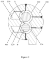
FIG. 2 is a first longitudinal sectional view of the screw compressor shown inFIG. 1 ; -
FIG. 3 is a cross-sectional view of the rotor housing of the screw compressor shown inFIG. 1 ; -
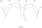
FIG. 4 is a structural schematic diagram of a partition plate of the screw compressor shown inFIG. 1 ; -
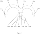
FIG. 5 is a structural schematic diagram of a partition plate of the screw compressor shown inFIG. 1 ; -
FIG. 6 is a second longitudinal sectional view of the screw compressor shown inFIG. 1 ; and -
FIG. 7 is a second longitudinal sectional view of the screw compressor shown inFIG. 1 with the rotor set omitted. - The content of the present invention and the differences between the present invention and the prior art can be understood by referring to the accompanying drawings and the text. The technical solution of the present invention will be described in further detail below through the accompanying drawings and by enumerating some optional embodiments of the present invention.
- It should be noted that any technical features or solutions in the embodiments are one or several of multiple optional technical features or technical solutions. For brevity, it is neither possible to exhaustively enumerate herein all alternative technical features and technical solutions of the present invention, nor is it possible to emphasize that the implementation of each technical feature is one of the optional multiple implementations. Therefore, those skilled in the art should be appreciate that any technical means provided by the present invention can be substituted, or any two or more technical means or technical features provided by the present invention can be combined with each other to obtain a new technical solution.
- Any technical feature or technical solution within the embodiments does not limit the scope of protection of the present invention. The scope of protection of the present invention should include any alternative technical solutions that those skilled in the art can think of without creative labor, as well as any new technical solutions obtained by those skilled in the art by combining any two or more technical means or technical features provided by the present invention.
-
FIG. 1 schematically illustrates the structure of an embodiment of a screw compressor according to the present invention in general. Thescrew compressor 10 is composed of arotor set 100, arotor housing 200 for accommodating therotor set 100, apartition plate 300, and other components. Therotor set 100 includes a pair ofmale rotor 110 andfemale rotor 120 meshing with each other and having spiral teeth in opposite rotating directions. Specifically, themale rotor 110 is composed of several male rotor teeth that are sequentially connected in the circumferential direction of the main shaft A, and thefemale rotor 120 is composed of several female rotor teeth that are sequentially connected in the circumferential direction of the main shaft B. Wherein, the gear ratio of the male rotor teeth and the female rotor teeth can be, for example, 5:7 or 6:8. As can be clearly seen fromFIGS. 1 and2 , the axis of the main shaft A of themale rotor 110 and the axis of the main shaft B of thefemale rotor 120 are parallel to each other, and themale rotor 110 and thefemale rotor 120 are respectively provided with grooves in the same radial direction. Wherein, the grooves of themale rotor 110 and those of thefemale rotor 120 are arranged circumferentially around themale rotor 110 and thefemale rotor 120 respectively and have the same width in the axial direction. Wherein, the bottom surface of the grooves of themale rotor 110 and the bottom surface of the grooves of thefemale rotor 120 are the outer circumference surface of the main shaft A of themale rotor 110 and the outer circumference surface of the main shaft B of thefemale rotor 120, respectively. - It should be emphasized that the
partition plate 300 is an important component of the two-stage screw compressor of the present invention, which constitutes the discharge port for low-pressure/first-stage compression and the suction port for high-pressure/second-stage compression. The basic structure of the partition plate and its relative positional relationship, mutual cooperation, and connection relationship with other surrounding components will be described in detail below in conjunction with the appended drawings. - In the embodiment shown in
FIGS. 1 to 4 , thepartition plate 300 is fixed to therotor housing 200, for example, by bolt connection, for dividing therotor housing 200 into a low-pressure stage housing 210 and a high-pressure stage housing 220 that are connected with each other. Wherein, the low-pressure stage housing 210 corresponds to a low-pressure stage rotor pair, and the high-pressure stage housing 220 corresponds to a high-pressure stage rotor pair. The starting end of the low-pressure stage rotor pair, i.e., the first-stage suction port 230, is located on therotor housing 200, especially on the low-pressure stage housing 210. The tail end of the low-pressure stage rotor pair, i.e., the first-stage discharge port 240, is located on one side of thepartition plate 300 facing the low-pressure stage housing 210. The starting end of the high-pressure stage rotor pair, i.e., the second-stage suction port 250, is located on one side of thepartition plate 300 facing the high-pressure stage housing 220, and the tail end of the high-pressure stage rotor pair, i.e., the second-stage discharge port 260, is located on therotor housing 200, especially on the high-pressure stage housing 220. - With continued reference to
FIG. 4 , thepartition plate 300 can be made of metal, such as high-strength steel, cast iron, or alloy, and includes a firstannular section 310 and a secondannular section 320 connected to each other. The firstannular section 310 and the secondannular section 320 are embedded in the grooves of themale rotor 110 and thefemale rotor 120, respectively. In addition, the width of the firstannular section 310 and that of the secondannular section 320 in the axial direction is the same or substantially the same as the width of the groove of themale rotor 110 and that of thefemale rotor 120 in the axial direction. For example, the width of the firstannular section 310 and that of the secondannular section 320 in the axial direction is slightly smaller than the width of the groove of themale rotor 110 and that of thefemale rotor 120 in the axial direction. Specifically, due to the relative motion between the rotor set 100 and thepartition plate 300, a small gap can be left between the two. In addition, in order to allow thepartition plate 300 to move axially during installation, the distance between thepartition plate 300 and the end face of the low-pressure stage rotor pair can be adjusted within a certain set distance, which is, for example, generally not greater than 0.1mm, and the distance between thepartition plate 300 and the end face of the high-pressure stage rotor pair is set to about 1mm. Furthermore, the firstannular section 310 has afree end 311 and a connectingend 312 connected to the secondannular section 320, and the secondannular section 320 has afree end 321 and a connectingend 322 connected to the firstannular section 310. In order to ensure the mutual flow of refrigerant gas between the low-pressure stage housing 210 and the high-pressure stage housing 220, a first connecting notch is formed circumferentially between thefree end 311 and the connectingend 312 of the firstannular section 310, and a second connecting notch is formed circumferentially between thefree end 321 and the connectingend 322 of the secondannular section 320, thereby forming the first-stage discharge port 240 and the second-stage suction port 250. At this point, the area of the first-stage discharge port 240 is the same as the area of the second-stage suction port 250. The range of the central angle of the firstannular section 310, i.e., the central angle of the circular arc section between thefree end 311 and the connectingend 312, is between X and 360° (excluding the endpoint), where X=360 ° - α , and α is cornerite of the low-pressure section of the male rotor. It should be noted that the cornerite of the low-pressure section of the male rotor is the circumferential angle swept from the suction end face to the discharge end face by the spiral movement of the tooth tip of the male rotor along the tooth space. The range of the central angle of the secondannular section 320, i.e., the central angle of the circular arc section between thefree end 321 and the connectingend 322, is between Y and 360° (excluding the endpoint), where Y=360 ° - β , and β is cornerite of the low-pressure section of the female rotor. It should be noted that the cornerite of the low-pressure section of the female rotor is the circumferential angle swept from the suction end face to the discharge end face by the spiral movement of the tooth tip of the female rotor along the tooth space. It can be seen that thepartition plate 300 reduces the radial area of refrigerant gas flow in the radial direction of the rotor set 100 and can effectively achieve second-stage compression. - In addition, the diameter of the annular outer surface of the first
annular section 310 is the same or substantially the same as the diameter of the circle where the tooth tips of the male rotor teeth of themale rotor 110 are located. For example, the diameter of the annular outer surface of the firstannular section 310 is slightly larger than the diameter of the circle where the tooth tips of the male rotor teeth of themale rotor 110 are located. Specifically, due to the relative rotation of themale rotor 110 and therotor housing 200, a small gap can be left between the two, and the annular outer surface of the firstannular section 310 can be tightly fixed to therotor housing 200. The diameter of the annular inner surface of the firstannular section 310 is the same or substantially the same as the diameter of the main shaft A of themale rotor 110. For example, the diameter of the annular inner surface of the firstannular section 310 is slightly larger than the diameter of the main shaft A of themale rotor 110. Meanwhile, the diameter of the annular outer surface of the secondannular section 320 is the same or substantially the same as the diameter of the circle where the tooth tips of the female rotor teeth of thefemale rotor 120 are located. For example, the diameter of the annular outer surface of the secondannular section 320 is slightly larger than the diameter of the circle where the tooth tips of the female rotor teeth of thefemale rotor 120 are located. Due to the relative rotation between thefemale rotor 120 and therotor housing 200, a small gap can be left between the two, and the annular outer surface of the secondannular section 320 can be tightly fixed to therotor housing 200. The diameter of the annular inner surface of the secondannular section 320 is the same or substantially the same as the diameter of the main shaft B of thefemale rotor 120. For example, the diameter of the annular inner surface of the secondannular section 320 is slightly larger than the diameter of the main shaft B of thefemale rotor 120. When installing a screw compressor, the operator can first embed or sleeve the firstannular section 310 and the secondannular section 320 of thepartition plate 300 into the groove of themale rotor 110 and that of thefemale rotor 120, respectively, and insert the rotor set 100 together with thepartition plate 300 into the accommodating chamber of therotor housing 200, thereby simplifying the installation steps. In this case, the low-pressure stage housing 210 and the high-pressure stage housing 220 can be constructed as one to form therotor housing 200, as shown inFIGS. 1 and4 . At this point, the annular outer surface of the firstannular section 310 and the annular outer surface of the secondannular section 320 of thepartition plate 300 can be fitted with the inner wall of therotor housing 200, making the internal space of therotor housing 200 more compact. This can save unnecessary bolts and bolt holes, reduce installation time, and save material costs. - In combination with the above embodiments, in other optional embodiments, the connecting
end 312 of the firstannular section 310 and the connectingend 322 of the secondannular section 320 form theintermediate section 330 of thepartition plate 300, where theintermediate section 330 is located between themale rotor 110 and thefemale rotor 120. For the convenience of manufacture, the firstannular section 310 and the secondannular section 320 can be integrally formed. In addition, in order to improve compression efficiency, thefree end 311 of the firstannular section 310 can be provided with outlines that are the same or similar to the contour outlines of the male rotor teeth of themale rotor 110, and thefree end 321 of the secondannular section 320 can be provided with outlines that are the same or similar to the contour outlines of the female rotor teeth of thefemale rotor 120. In addition, theintermediate section 330 is provided with outlines that are the same or similar to the contour outlines of the male rotor teeth of themale rotor 110, and/or the outlines that are the same or similar to the contour outlines of the female rotor teeth of thefemale rotor 120. - In another embodiment of the partition plate of the screw compressor disclosed according to the present invention as shown in
FIG. 5 , the firstannular section 310a, the secondannular section 320a, theintermediate section 330a, thefree end 311a and the connectingend 312a of the firstannular section 310a, thefree end 321a and the connectingend 322a of the secondannular section 320a, and other parts or components of thepartition plate 300a can refer to the aforementioned embodiment of thepartition plate 300 as shown inFIG.4 , which will not be repeated here. Thepartition 300a further comprises a firstannular extension section 340a and a secondannular extension section 350a. The firstannular extension section 340a is embedded in the groove of themale rotor 110, with oneend 341a thereof connected to the connectingend 312a of the firstannular section 310a. And, the secondannular extension section 350a is embedded in the groove of thefemale rotor 120, with oneend 351a thereof connected to the connectingend 322a of the secondannular section 320a. The diameter of the annular outer surface of the firstannular extension section 340a is the same as the diameter of the circle where the tooth tips of the male rotor teeth of themale rotor 110 are located, and the diameter of the annular inner surface of the firstannular extension section 340a is the same or substantially the same as the diameter of the main shaft A of themale rotor 110. In addition, the diameter of the annular outer surface of the secondannular extension section 350a is the same as the diameter of the circle where the tooth tips of the female rotor teeth of thefemale rotor 120 are located, and the diameter of the annular inner surface of the secondannular extension section 350a is the same or substantially the same as the diameter of the main shaft B of thefemale rotor 120. - On the one hand, the end face of the first
annular extension section 340a facing the high-pressure stage housing 220 is configured to be flush with the end face of the firstannular section 310a facing the high-pressure stage housing 220, and the end face of the secondannular extension section 350a facing the high-pressure stage housing 220 is configured to be flush with the end face of the secondannular section 320a facing the high-pressure stage housing 220. On the other hand, the width of the firstannular extension section 340a in the axial direction is the same as the width of the secondannular extension section 350a in the axial direction, and is smaller than the width of the firstannular section 310a in the axial direction and the width of the secondannular section 320a in the axial direction, so that the area of the second-stage suction port 250 is smaller than the area of the first-stage discharge port 240, thus further improving the compression ratio of the second stage. - For the convenience of manufacture, the first
annular extension section 340a and the secondannular extension section 350a can be designed to be integrally formed with the firstannular section 310a and the secondannular section 320a. In this case, in order to install the integrally formedpartition plate 300a into the groove of the rotor set 100, thepartition plate 300a can be divided into independent two or more sections along the dashed line inFIG. 5 at theintermediate section 330. In addition, in order to improve compression efficiency, theother end 342a of the firstannular extension section 340a is provided with outlines that are the same or similar to the contour outlines of the male rotor teeth of themale rotor 110, and theother end 352a of the secondannular extension section 350a is provided with outlines that are the same or similar to the contour outlines of the female rotor teeth of thefemale rotor 120. - Those skilled in the art can readily contemplate that the annular inner surface of the first
annular section 310a, the annular inner surface of the secondannular section 320a, the annular inner surface of the firstannular extension section 340a, and the annular inner surface of the secondannular extension section 350a are respectively provided with seal structures (not shown), such as labyrinth seal structures, or contact or non-contact rotary seal structures such as oil groove seals, sliding ring seals, lip seals, etc., so as to prevent refrigerant gas leakage. In this case, the gap between the inner diameter of the seal structure and the bottom surface of the grooves of the rotor set is designed to be no more than 2mm. - As an alternative solution, the
screw compressor 10 also comprises agas replenishment structure 400 for introducing refrigerant gas from, for example, an economizer, into the second-stage suction port 250. Specifically, the gas replenishment structure is arranged at the high-pressure stage housing 220, and thegas replenishment structure 400 is connected to the high-pressure stage suction chamber (i.e., the position of the second-stage suction port 250). Referring toFIGS. 1 ,3 ,6 , and7 , the refrigerant gas used for gas replenishment can be first transported to thegas replenishment chamber 420 to be mixed with the discharged gas that has undergone low-pressure/first-stage compression as soon as possible, and the gas pressure is stabilized in thegas replenishment chamber 420 before the refrigerant gas enters the second-stage suction port 250, thereby ensuring the stability of the suction pressure of the high-pressure stage rotor pair so as to further optimize the compression effect of the second-stage compression. - In addition, the present invention further provides a refrigeration system configured with the aforementioned screw compressor. The refrigeration system comprises a cooling tower, a water chilling unit, and a pumping device, etc. connected through pipelines, wherein the water chilling unit is composed of the aforementioned screw compressor, a condenser, a throttling device, an evaporator, and other components connected into a circuit.
- If terms such as "first" and "second" are used herein to limit components, those skilled in the art should be aware that the use of "first" and "second" is only for the purpose of distinguishing components in terms of depiction. Unless otherwise stated, the above terms do not have any special meanings.
- Furthermore, as to the terms used to indicate positional relationships or shapes in any of the technical solutions disclosed in the present invention, unless otherwise stated, the implications thereof include states or shapes that are approximate, similar, or close to them. Any component provided by the present invention can be either assembled from multiple individual components or manufactured as a separate component using an integration process.
- If terms such as "center", "longitudinal", "transverse", "front", "back", "left", "right", "vertical", "horizontal", "top", "bottom", "inside", "outside", etc. are used in the depiction of the present invention, the orientations or positional relationships indicated by the above terms are based on the orientations or positional relationships shown in the drawings. These terms are used merely for the convenience of describing the present invention and simplifying the description, rather than indicating or implying that the device, mechanism, component or element referred to must have a specific orientation, be constructed and operated in a specific orientation, so they cannot be understood as forming limitations on the scope of protection of the present invention.
- Last, it should be noted that the above embodiments are only used to illustrate the technical solution of the present invention but not to limit it. Although the present invention has been described in detail with reference to preferred embodiments, those skilled in the art, however, should understand that the specific embodiments of the present invention as described herein are provided by way of example only. The scope of protection is defined by the appended claims.
Claims (12)
- A screw compressor (10), comprising:a rotor set (100) comprising a pair of male rotor (110) and female rotor (120) meshing with each other, where axis of a main shaft of the male rotor and axis of a main shaft of the female rotor are parallel to each other, and the male rotor and the female rotor are respectively provided with grooves with the same width in an axial direction that are arranged circumferentially around them in the same radial direction, wherein a bottom surface of grooves of the male rotor and a bottom surface of grooves of the female rotor are an outer circumferential surface of the main shaft of the male rotor and an outer circumferential surface of the main shaft of the female rotor, respectively;a rotor housing (200) for accommodating the rotor set; anda partition plate (300), fixed on the rotor housing, for dividing the rotor housing into a low-pressure stage housing (210) and a high-pressure stage housing (220) connected to each other, wherein the partition plate has a first annular section (310) and a second annular section (320) connected to each other, where the first annular section and the second annular section are respectively embedded in a groove of the male rotor and that of the female rotor and have the same or substantially the same width in the axial direction as the groove of the male rotor and that of the female rotor, and the first annular section has a free end (311) and a connecting end (312) connected to the second annular section, and the second annular section has a free end (321) and a connecting end (322) connected to the first annular section;wherein, a diameter of an annular outer surface of the first annular section is the same or substantially the same as a diameter of a circle where tooth tips of male rotor teeth of the male rotor are located, and a diameter of an annular inner surface of the first annular section is the same or substantially the same as a diameter of the main shaft of the male rotor; and wherein, a diameter of an annular outer surface of the second annular section is the same or substantially the same as a diameter of a circle where tooth tips of female rotor teeth of the female rotor are located, and a diameter of an annular inner surface of the second annular section is the same or substantially the same as a diameter of the main shaft of the female rotor
- The screw compressor according to claim 1, wherein the connecting end of the first annular section and the connecting end of the second annular section form an intermediate section of the partition plate, where the intermediate section is located between the male rotor and the female rotor.
- The screw compressor according to claim 2, wherein the first annular section and the second annular section are integrally formed.
- The screw compressor according to claim 2 or 3, wherein the free end of the first annular section is provided with outlines that are the same or similar to contour outlines of male rotor teeth of the male rotor, the free end of the second annular section is provided with outlines that are the same or similar to contour outlines of female rotor tooth of the female rotor, and the intermediate section is provided with outlines that are the same or similar to contour outlines of male rotor teeth of the male rotor and/or outlines that are the same or similar to contour outlines of female rotor teeth of the female rotor.
- The screw compressor according to claim 2 or 3, wherein the partition plate further comprises a first annular extension section and a second annular extension section, where the first annular extension section is embedded in a groove of the male rotor, with one end thereof connected to the connecting end of the first annular section, and the second annular extension section is embedded in a groove of the female rotor, with one end thereof connected to the connecting end of the second annular section,wherein, a diameter of an annular outer surface of the first annular extension section is the same as a diameter of a circle where tooth tips of male rotor teeth of the male rotor are located, and a diameter of an annular inner surface of the first annular extension section is the same or substantially the same as the diameter of the main shaft of the male rotor; and wherein, a diameter of an annular outer surface of the second annular extension section is the same as a diameter of a circle where tooth tips of female rotor teeth of the female rotor are located, and a diameter of an annular inner surface of the second annular extension section is the same or substantially the same as the diameter of the main shaft of the female rotor;wherein, an end face of the first annular extension section facing the high-pressure stage housing is flush with an end face of the first annular section facing the high-pressure stage housing, and an end face of the second annular extension section facing the high-pressure stage housing is flush with an end face of the second annular section facing the high-pressure stage housing; and wherein, a width of the first annular extension section in the axial direction is the same as a width of the second annular extension section in the axial direction, and is smaller than a width of the first annular section in the axial direction and a width of the second annular section in the axial direction.
- The screw compressor according to claim 5, wherein the other end of the first annular extension section is provided with outlines that are the same or similar to contour outlines of male rotor teeth of the male rotor, and the other end of the second annular extension section is provided with outlines that are the same or similar to contour outline of female rotor teeth of the female rotor.
- The screw compressor according to claim 5, wherein the first annular extension section, the second annular extension section, the first annular section, and the second annular section are integrally formed.
- The screw compressor according to claim 5, wherein seal structures are respectively provided on the annular inner surface of the first annular section, the annular inner surface of the second annular section, the annular inner surface of the first annular extension section, and the annular inner surface of the second annular extension section.
- The screw compressor according to any of claims 1-3, wherein the partition plate is made of metal; and/or the partition plate is fixed to the rotor housing by bolt connection.
- The screw compressor according to any of claims 1-3, wherein the low-pressure stage housing and the high-pressure stage housing are integrally constructed to form the rotor housing.
- The screw compressor according to any of claims 1-3, wherein the screw compressor comprises a gas replenishment structure (400) that is arranged at the high-pressure stage housing and connected to a high-pressure stage suction chamber.
- A refrigeration system, wherein the refrigeration system is configured with the screw compressor according to any of claims 1-11, a condenser, a throttling device, and an evaporator connected into a circuit.
Applications Claiming Priority (1)
| Application Number | Priority Date | Filing Date | Title |
|---|---|---|---|
| CN202320402495.5U CN219281960U (en) | 2023-02-27 | 2023-02-27 | Screw compressor and refrigeration system with same |
Publications (1)
| Publication Number | Publication Date |
|---|---|
| EP4421322A1 true EP4421322A1 (en) | 2024-08-28 |
Family
ID=86917537
Family Applications (1)
| Application Number | Title | Priority Date | Filing Date |
|---|---|---|---|
| EP24160065.9A Pending EP4421322A1 (en) | 2023-02-27 | 2024-02-27 | Screw compressor and refrigeration system having the same |
Country Status (3)
| Country | Link |
|---|---|
| US (1) | US20240287990A1 (en) |
| EP (1) | EP4421322A1 (en) |
| CN (1) | CN219281960U (en) |
Families Citing this family (1)
| Publication number | Priority date | Publication date | Assignee | Title |
|---|---|---|---|---|
| CN113982933B (en) * | 2021-11-09 | 2025-11-25 | 珠海格力电器股份有限公司 | Exhaust end bearing housing and screw compressor with such bearing housing, air conditioning system |
Citations (3)
| Publication number | Priority date | Publication date | Assignee | Title |
|---|---|---|---|---|
| US3209990A (en) * | 1962-01-18 | 1965-10-05 | Atlas Copco Ab | Two stage screw rotor machines |
| CN106704179A (en) * | 2017-03-09 | 2017-05-24 | 上海格什特螺杆科技有限公司 | Novel direct-connected dual-screw compressor |
| US20220112895A1 (en) * | 2019-02-06 | 2022-04-14 | Hitachi Industrial Equipment Systems Co., Ltd. | Multi-Stage Screw Compressor |
Family Cites Families (3)
| Publication number | Priority date | Publication date | Assignee | Title |
|---|---|---|---|---|
| US3102681A (en) * | 1959-06-17 | 1963-09-03 | Svenska Rotor Maskiner Ab | Improvements in housing constructions for rotary piston engines |
| SE303170B (en) * | 1963-09-12 | 1968-08-19 | Svenska Rotor Maskiner Ab | |
| DE102006021704B4 (en) * | 2006-05-10 | 2018-01-04 | Gea Refrigeration Germany Gmbh | Screw compressor for large power outputs |
-
2023
- 2023-02-27 CN CN202320402495.5U patent/CN219281960U/en active Active
-
2024
- 2024-02-26 US US18/587,398 patent/US20240287990A1/en active Pending
- 2024-02-27 EP EP24160065.9A patent/EP4421322A1/en active Pending
Patent Citations (3)
| Publication number | Priority date | Publication date | Assignee | Title |
|---|---|---|---|---|
| US3209990A (en) * | 1962-01-18 | 1965-10-05 | Atlas Copco Ab | Two stage screw rotor machines |
| CN106704179A (en) * | 2017-03-09 | 2017-05-24 | 上海格什特螺杆科技有限公司 | Novel direct-connected dual-screw compressor |
| US20220112895A1 (en) * | 2019-02-06 | 2022-04-14 | Hitachi Industrial Equipment Systems Co., Ltd. | Multi-Stage Screw Compressor |
Also Published As
| Publication number | Publication date |
|---|---|
| CN219281960U (en) | 2023-06-30 |
| US20240287990A1 (en) | 2024-08-29 |
Similar Documents
| Publication | Publication Date | Title |
|---|---|---|
| US4650405A (en) | Scroll pump with axially spaced pumping chambers in series | |
| US11280337B2 (en) | Pump body assembly and compressor having crank shaft with eccentric components, disc partition plate, and annular partition plate | |
| US7618248B2 (en) | Screw compressor with intermediate plate | |
| EP3392507A1 (en) | Sliding vane control structure for variable-capacity air cylinder, variable-capacity air cylinder and variable-capacity compressor | |
| US7641454B2 (en) | Two-stage rotary compressor | |
| JP2013199841A (en) | Scroll compressor and processing method of scroll | |
| US8475149B2 (en) | Scroll fluid machine having multiple discharge ports | |
| US20240287990A1 (en) | Screw compressor and refrigeration system having it | |
| US20110064596A1 (en) | Scroll compressor | |
| US20100054978A1 (en) | Injectible two-stage compression rotary compressor | |
| EP1850006A2 (en) | Scroll compressor | |
| CN111720312A (en) | Rotary compressors and refrigeration cycle systems | |
| US10006460B2 (en) | Hermetic compressor having enlarged suction inlet | |
| US7753665B2 (en) | Screw compressor for working pressures above 80 bar | |
| CN204312325U (en) | hermetic compressor | |
| US20070059193A1 (en) | Scroll compressor with vapor injection | |
| EP1830069B1 (en) | Rotary compressor | |
| KR20220044023A (en) | compressor | |
| CN116464642A (en) | Oil return throttling device and scroll compressor | |
| CN116906324B (en) | Scroll compressors and refrigeration equipment | |
| US6663369B2 (en) | Fluid compressor | |
| CN220850013U (en) | Scroll compressor and refrigeration equipment | |
| CN220667824U (en) | Piston for compressor and compressor | |
| CN113978206B (en) | Front cyclone blade type automobile air conditioner compressor | |
| CN115126697B (en) | Compressor pump body, compressor and temperature regulating system |
Legal Events
| Date | Code | Title | Description |
|---|---|---|---|
| PUAI | Public reference made under article 153(3) epc to a published international application that has entered the european phase |
Free format text: ORIGINAL CODE: 0009012 |
|
| STAA | Information on the status of an ep patent application or granted ep patent |
Free format text: STATUS: THE APPLICATION HAS BEEN PUBLISHED |
|
| AK | Designated contracting states |
Kind code of ref document: A1 Designated state(s): AL AT BE BG CH CY CZ DE DK EE ES FI FR GB GR HR HU IE IS IT LI LT LU LV MC ME MK MT NL NO PL PT RO RS SE SI SK SM TR |
|
| STAA | Information on the status of an ep patent application or granted ep patent |
Free format text: STATUS: REQUEST FOR EXAMINATION WAS MADE |
|
| 17P | Request for examination filed |
Effective date: 20250218 |
|
| GRAP | Despatch of communication of intention to grant a patent |
Free format text: ORIGINAL CODE: EPIDOSNIGR1 |
|
| STAA | Information on the status of an ep patent application or granted ep patent |
Free format text: STATUS: GRANT OF PATENT IS INTENDED |
|
| RIC1 | Information provided on ipc code assigned before grant |
Ipc: F04C 18/16 20060101AFI20260319BHEP Ipc: F04C 23/00 20060101ALI20260319BHEP |
|
| INTG | Intention to grant announced |
Effective date: 20260407 |