EP4421292A1 - Coating system and method for maintenance thereof - Google Patents
Coating system and method for maintenance thereof Download PDFInfo
- Publication number
- EP4421292A1 EP4421292A1 EP24154325.5A EP24154325A EP4421292A1 EP 4421292 A1 EP4421292 A1 EP 4421292A1 EP 24154325 A EP24154325 A EP 24154325A EP 4421292 A1 EP4421292 A1 EP 4421292A1
- Authority
- EP
- European Patent Office
- Prior art keywords
- layer
- coating system
- article
- thermal barrier
- barrier layer
- Prior art date
- Legal status (The legal status is an assumption and is not a legal conclusion. Google has not performed a legal analysis and makes no representation as to the accuracy of the status listed.)
- Pending
Links
- 239000011248 coating agent Substances 0.000 title claims abstract description 91
- 238000000576 coating method Methods 0.000 title claims abstract description 91
- 238000000034 method Methods 0.000 title claims description 46
- 238000012423 maintenance Methods 0.000 title 1
- 230000004888 barrier function Effects 0.000 claims abstract description 94
- MCMNRKCIXSYSNV-UHFFFAOYSA-N Zirconium dioxide Chemical compound O=[Zr]=O MCMNRKCIXSYSNV-UHFFFAOYSA-N 0.000 claims abstract description 9
- 229910052596 spinel Inorganic materials 0.000 claims abstract description 7
- 239000011029 spinel Substances 0.000 claims abstract description 7
- FYYHWMGAXLPEAU-UHFFFAOYSA-N Magnesium Chemical compound [Mg] FYYHWMGAXLPEAU-UHFFFAOYSA-N 0.000 claims abstract description 6
- 229910052749 magnesium Inorganic materials 0.000 claims abstract description 6
- 239000011777 magnesium Substances 0.000 claims abstract description 6
- RUDFQVOCFDJEEF-UHFFFAOYSA-N yttrium(III) oxide Inorganic materials [O-2].[O-2].[O-2].[Y+3].[Y+3] RUDFQVOCFDJEEF-UHFFFAOYSA-N 0.000 claims abstract description 4
- 210000004027 cell Anatomy 0.000 claims description 38
- XLYOFNOQVPJJNP-UHFFFAOYSA-N water Substances O XLYOFNOQVPJJNP-UHFFFAOYSA-N 0.000 claims description 38
- 239000000758 substrate Substances 0.000 claims description 27
- 210000002421 cell wall Anatomy 0.000 claims description 23
- 230000033001 locomotion Effects 0.000 claims description 12
- 230000007613 environmental effect Effects 0.000 description 10
- PXHVJJICTQNCMI-UHFFFAOYSA-N Nickel Chemical compound [Ni] PXHVJJICTQNCMI-UHFFFAOYSA-N 0.000 description 7
- 238000000151 deposition Methods 0.000 description 7
- 238000005240 physical vapour deposition Methods 0.000 description 6
- 239000003518 caustics Substances 0.000 description 5
- 229910045601 alloy Inorganic materials 0.000 description 4
- 239000000956 alloy Substances 0.000 description 4
- 238000002485 combustion reaction Methods 0.000 description 4
- 239000000463 material Substances 0.000 description 4
- 238000007750 plasma spraying Methods 0.000 description 4
- 230000001141 propulsive effect Effects 0.000 description 4
- 239000011651 chromium Substances 0.000 description 3
- 230000008021 deposition Effects 0.000 description 3
- 239000000203 mixture Substances 0.000 description 3
- 229910052759 nickel Inorganic materials 0.000 description 3
- 238000011144 upstream manufacturing Methods 0.000 description 3
- VYZAMTAEIAYCRO-UHFFFAOYSA-N Chromium Chemical compound [Cr] VYZAMTAEIAYCRO-UHFFFAOYSA-N 0.000 description 2
- 239000004411 aluminium Substances 0.000 description 2
- 229910052782 aluminium Inorganic materials 0.000 description 2
- XAGFODPZIPBFFR-UHFFFAOYSA-N aluminium Chemical compound [Al] XAGFODPZIPBFFR-UHFFFAOYSA-N 0.000 description 2
- 229910052804 chromium Inorganic materials 0.000 description 2
- 239000010941 cobalt Substances 0.000 description 2
- 229910017052 cobalt Inorganic materials 0.000 description 2
- GUTLYIVDDKVIGB-UHFFFAOYSA-N cobalt atom Chemical compound [Co] GUTLYIVDDKVIGB-UHFFFAOYSA-N 0.000 description 2
- 239000002131 composite material Substances 0.000 description 2
- 230000006835 compression Effects 0.000 description 2
- 238000007906 compression Methods 0.000 description 2
- 238000010290 vacuum plasma spraying Methods 0.000 description 2
- 229910001233 yttria-stabilized zirconia Inorganic materials 0.000 description 2
- 229910052727 yttrium Inorganic materials 0.000 description 2
- VWQVUPCCIRVNHF-UHFFFAOYSA-N yttrium atom Chemical compound [Y] VWQVUPCCIRVNHF-UHFFFAOYSA-N 0.000 description 2
- OKTJSMMVPCPJKN-UHFFFAOYSA-N Carbon Chemical compound [C] OKTJSMMVPCPJKN-UHFFFAOYSA-N 0.000 description 1
- 229910000531 Co alloy Inorganic materials 0.000 description 1
- ZOKXTWBITQBERF-UHFFFAOYSA-N Molybdenum Chemical compound [Mo] ZOKXTWBITQBERF-UHFFFAOYSA-N 0.000 description 1
- GANNOFFDYMSBSZ-UHFFFAOYSA-N [AlH3].[Mg] Chemical compound [AlH3].[Mg] GANNOFFDYMSBSZ-UHFFFAOYSA-N 0.000 description 1
- 238000005270 abrasive blasting Methods 0.000 description 1
- 239000002318 adhesion promoter Substances 0.000 description 1
- 230000009286 beneficial effect Effects 0.000 description 1
- 230000015572 biosynthetic process Effects 0.000 description 1
- 229910052799 carbon Inorganic materials 0.000 description 1
- 238000000541 cathodic arc deposition Methods 0.000 description 1
- 239000000919 ceramic Substances 0.000 description 1
- 150000001875 compounds Chemical class 0.000 description 1
- 238000005260 corrosion Methods 0.000 description 1
- 230000007797 corrosion Effects 0.000 description 1
- 238000005336 cracking Methods 0.000 description 1
- 239000013078 crystal Substances 0.000 description 1
- 238000010586 diagram Methods 0.000 description 1
- 239000000835 fiber Substances 0.000 description 1
- 239000000446 fuel Substances 0.000 description 1
- 230000012010 growth Effects 0.000 description 1
- 239000012535 impurity Substances 0.000 description 1
- 229910052500 inorganic mineral Inorganic materials 0.000 description 1
- UGKDIUIOSMUOAW-UHFFFAOYSA-N iron nickel Chemical compound [Fe].[Ni] UGKDIUIOSMUOAW-UHFFFAOYSA-N 0.000 description 1
- 238000003754 machining Methods 0.000 description 1
- 239000011159 matrix material Substances 0.000 description 1
- 229910052751 metal Inorganic materials 0.000 description 1
- 239000002184 metal Substances 0.000 description 1
- 229910001092 metal group alloy Inorganic materials 0.000 description 1
- 239000011156 metal matrix composite Substances 0.000 description 1
- 239000011707 mineral Substances 0.000 description 1
- 229910052750 molybdenum Inorganic materials 0.000 description 1
- 239000011733 molybdenum Substances 0.000 description 1
- 229910052758 niobium Inorganic materials 0.000 description 1
- 239000010955 niobium Substances 0.000 description 1
- GUCVJGMIXFAOAE-UHFFFAOYSA-N niobium atom Chemical compound [Nb] GUCVJGMIXFAOAE-UHFFFAOYSA-N 0.000 description 1
- 230000003647 oxidation Effects 0.000 description 1
- 238000007254 oxidation reaction Methods 0.000 description 1
- SIWVEOZUMHYXCS-UHFFFAOYSA-N oxo(oxoyttriooxy)yttrium Chemical compound O=[Y]O[Y]=O SIWVEOZUMHYXCS-UHFFFAOYSA-N 0.000 description 1
- RVTZCBVAJQQJTK-UHFFFAOYSA-N oxygen(2-);zirconium(4+) Chemical compound [O-2].[O-2].[Zr+4] RVTZCBVAJQQJTK-UHFFFAOYSA-N 0.000 description 1
- 238000004886 process control Methods 0.000 description 1
- 238000009877 rendering Methods 0.000 description 1
- 239000002002 slurry Substances 0.000 description 1
- 239000007921 spray Substances 0.000 description 1
- 238000005507 spraying Methods 0.000 description 1
- 238000004544 sputter deposition Methods 0.000 description 1
- 239000000126 substance Substances 0.000 description 1
- 239000000725 suspension Substances 0.000 description 1
Images



Classifications
-
- C—CHEMISTRY; METALLURGY
- C04—CEMENTS; CONCRETE; ARTIFICIAL STONE; CERAMICS; REFRACTORIES
- C04B—LIME, MAGNESIA; SLAG; CEMENTS; COMPOSITIONS THEREOF, e.g. MORTARS, CONCRETE OR LIKE BUILDING MATERIALS; ARTIFICIAL STONE; CERAMICS; REFRACTORIES; TREATMENT OF NATURAL STONE
- C04B35/00—Shaped ceramic products characterised by their composition; Ceramics compositions; Processing powders of inorganic compounds preparatory to the manufacturing of ceramic products
- C04B35/01—Shaped ceramic products characterised by their composition; Ceramics compositions; Processing powders of inorganic compounds preparatory to the manufacturing of ceramic products based on oxide ceramics
- C04B35/48—Shaped ceramic products characterised by their composition; Ceramics compositions; Processing powders of inorganic compounds preparatory to the manufacturing of ceramic products based on oxide ceramics based on zirconium or hafnium oxides, zirconates, zircon or hafnates
- C04B35/486—Fine ceramics
-
- C—CHEMISTRY; METALLURGY
- C23—COATING METALLIC MATERIAL; COATING MATERIAL WITH METALLIC MATERIAL; CHEMICAL SURFACE TREATMENT; DIFFUSION TREATMENT OF METALLIC MATERIAL; COATING BY VACUUM EVAPORATION, BY SPUTTERING, BY ION IMPLANTATION OR BY CHEMICAL VAPOUR DEPOSITION, IN GENERAL; INHIBITING CORROSION OF METALLIC MATERIAL OR INCRUSTATION IN GENERAL
- C23C—COATING METALLIC MATERIAL; COATING MATERIAL WITH METALLIC MATERIAL; SURFACE TREATMENT OF METALLIC MATERIAL BY DIFFUSION INTO THE SURFACE, BY CHEMICAL CONVERSION OR SUBSTITUTION; COATING BY VACUUM EVAPORATION, BY SPUTTERING, BY ION IMPLANTATION OR BY CHEMICAL VAPOUR DEPOSITION, IN GENERAL
- C23C28/00—Coating for obtaining at least two superposed coatings either by methods not provided for in a single one of groups C23C2/00 - C23C26/00 or by combinations of methods provided for in subclasses C23C and C25C or C25D
- C23C28/30—Coatings combining at least one metallic layer and at least one inorganic non-metallic layer
- C23C28/32—Coatings combining at least one metallic layer and at least one inorganic non-metallic layer including at least one pure metallic layer
- C23C28/321—Coatings combining at least one metallic layer and at least one inorganic non-metallic layer including at least one pure metallic layer with at least one metal alloy layer
- C23C28/3215—Coatings combining at least one metallic layer and at least one inorganic non-metallic layer including at least one pure metallic layer with at least one metal alloy layer at least one MCrAlX layer
-
- C—CHEMISTRY; METALLURGY
- C04—CEMENTS; CONCRETE; ARTIFICIAL STONE; CERAMICS; REFRACTORIES
- C04B—LIME, MAGNESIA; SLAG; CEMENTS; COMPOSITIONS THEREOF, e.g. MORTARS, CONCRETE OR LIKE BUILDING MATERIALS; ARTIFICIAL STONE; CERAMICS; REFRACTORIES; TREATMENT OF NATURAL STONE
- C04B35/00—Shaped ceramic products characterised by their composition; Ceramics compositions; Processing powders of inorganic compounds preparatory to the manufacturing of ceramic products
- C04B35/01—Shaped ceramic products characterised by their composition; Ceramics compositions; Processing powders of inorganic compounds preparatory to the manufacturing of ceramic products based on oxide ceramics
- C04B35/48—Shaped ceramic products characterised by their composition; Ceramics compositions; Processing powders of inorganic compounds preparatory to the manufacturing of ceramic products based on oxide ceramics based on zirconium or hafnium oxides, zirconates, zircon or hafnates
- C04B35/482—Refractories from grain sized mixtures
-
- C—CHEMISTRY; METALLURGY
- C04—CEMENTS; CONCRETE; ARTIFICIAL STONE; CERAMICS; REFRACTORIES
- C04B—LIME, MAGNESIA; SLAG; CEMENTS; COMPOSITIONS THEREOF, e.g. MORTARS, CONCRETE OR LIKE BUILDING MATERIALS; ARTIFICIAL STONE; CERAMICS; REFRACTORIES; TREATMENT OF NATURAL STONE
- C04B35/00—Shaped ceramic products characterised by their composition; Ceramics compositions; Processing powders of inorganic compounds preparatory to the manufacturing of ceramic products
- C04B35/622—Forming processes; Processing powders of inorganic compounds preparatory to the manufacturing of ceramic products
- C04B35/626—Preparing or treating the powders individually or as batches ; preparing or treating macroscopic reinforcing agents for ceramic products, e.g. fibres; mechanical aspects section B
- C04B35/62605—Treating the starting powders individually or as mixtures
- C04B35/62645—Thermal treatment of powders or mixtures thereof other than sintering
- C04B35/62665—Flame, plasma or melting treatment
-
- C—CHEMISTRY; METALLURGY
- C23—COATING METALLIC MATERIAL; COATING MATERIAL WITH METALLIC MATERIAL; CHEMICAL SURFACE TREATMENT; DIFFUSION TREATMENT OF METALLIC MATERIAL; COATING BY VACUUM EVAPORATION, BY SPUTTERING, BY ION IMPLANTATION OR BY CHEMICAL VAPOUR DEPOSITION, IN GENERAL; INHIBITING CORROSION OF METALLIC MATERIAL OR INCRUSTATION IN GENERAL
- C23C—COATING METALLIC MATERIAL; COATING MATERIAL WITH METALLIC MATERIAL; SURFACE TREATMENT OF METALLIC MATERIAL BY DIFFUSION INTO THE SURFACE, BY CHEMICAL CONVERSION OR SUBSTITUTION; COATING BY VACUUM EVAPORATION, BY SPUTTERING, BY ION IMPLANTATION OR BY CHEMICAL VAPOUR DEPOSITION, IN GENERAL
- C23C28/00—Coating for obtaining at least two superposed coatings either by methods not provided for in a single one of groups C23C2/00 - C23C26/00 or by combinations of methods provided for in subclasses C23C and C25C or C25D
- C23C28/30—Coatings combining at least one metallic layer and at least one inorganic non-metallic layer
- C23C28/34—Coatings combining at least one metallic layer and at least one inorganic non-metallic layer including at least one inorganic non-metallic material layer, e.g. metal carbide, nitride, boride, silicide layer and their mixtures, enamels, phosphates and sulphates
-
- C—CHEMISTRY; METALLURGY
- C23—COATING METALLIC MATERIAL; COATING MATERIAL WITH METALLIC MATERIAL; CHEMICAL SURFACE TREATMENT; DIFFUSION TREATMENT OF METALLIC MATERIAL; COATING BY VACUUM EVAPORATION, BY SPUTTERING, BY ION IMPLANTATION OR BY CHEMICAL VAPOUR DEPOSITION, IN GENERAL; INHIBITING CORROSION OF METALLIC MATERIAL OR INCRUSTATION IN GENERAL
- C23C—COATING METALLIC MATERIAL; COATING MATERIAL WITH METALLIC MATERIAL; SURFACE TREATMENT OF METALLIC MATERIAL BY DIFFUSION INTO THE SURFACE, BY CHEMICAL CONVERSION OR SUBSTITUTION; COATING BY VACUUM EVAPORATION, BY SPUTTERING, BY ION IMPLANTATION OR BY CHEMICAL VAPOUR DEPOSITION, IN GENERAL
- C23C28/00—Coating for obtaining at least two superposed coatings either by methods not provided for in a single one of groups C23C2/00 - C23C26/00 or by combinations of methods provided for in subclasses C23C and C25C or C25D
- C23C28/30—Coatings combining at least one metallic layer and at least one inorganic non-metallic layer
- C23C28/34—Coatings combining at least one metallic layer and at least one inorganic non-metallic layer including at least one inorganic non-metallic material layer, e.g. metal carbide, nitride, boride, silicide layer and their mixtures, enamels, phosphates and sulphates
- C23C28/345—Coatings combining at least one metallic layer and at least one inorganic non-metallic layer including at least one inorganic non-metallic material layer, e.g. metal carbide, nitride, boride, silicide layer and their mixtures, enamels, phosphates and sulphates with at least one oxide layer
- C23C28/3455—Coatings combining at least one metallic layer and at least one inorganic non-metallic layer including at least one inorganic non-metallic material layer, e.g. metal carbide, nitride, boride, silicide layer and their mixtures, enamels, phosphates and sulphates with at least one oxide layer with a refractory ceramic layer, e.g. refractory metal oxide, ZrO2, rare earth oxides or a thermal barrier system comprising at least one refractory oxide layer
-
- F—MECHANICAL ENGINEERING; LIGHTING; HEATING; WEAPONS; BLASTING
- F01—MACHINES OR ENGINES IN GENERAL; ENGINE PLANTS IN GENERAL; STEAM ENGINES
- F01D—NON-POSITIVE DISPLACEMENT MACHINES OR ENGINES, e.g. STEAM TURBINES
- F01D25/00—Component parts, details, or accessories, not provided for in, or of interest apart from, other groups
- F01D25/002—Cleaning of turbomachines
-
- F—MECHANICAL ENGINEERING; LIGHTING; HEATING; WEAPONS; BLASTING
- F01—MACHINES OR ENGINES IN GENERAL; ENGINE PLANTS IN GENERAL; STEAM ENGINES
- F01D—NON-POSITIVE DISPLACEMENT MACHINES OR ENGINES, e.g. STEAM TURBINES
- F01D5/00—Blades; Blade-carrying members; Heating, heat-insulating, cooling or antivibration means on the blades or the members
- F01D5/005—Repairing methods or devices
-
- F—MECHANICAL ENGINEERING; LIGHTING; HEATING; WEAPONS; BLASTING
- F01—MACHINES OR ENGINES IN GENERAL; ENGINE PLANTS IN GENERAL; STEAM ENGINES
- F01D—NON-POSITIVE DISPLACEMENT MACHINES OR ENGINES, e.g. STEAM TURBINES
- F01D5/00—Blades; Blade-carrying members; Heating, heat-insulating, cooling or antivibration means on the blades or the members
- F01D5/12—Blades
- F01D5/28—Selecting particular materials; Particular measures relating thereto; Measures against erosion or corrosion
- F01D5/288—Protective coatings for blades
-
- B—PERFORMING OPERATIONS; TRANSPORTING
- B08—CLEANING
- B08B—CLEANING IN GENERAL; PREVENTION OF FOULING IN GENERAL
- B08B3/00—Cleaning by methods involving the use or presence of liquid or steam
- B08B3/02—Cleaning by the force of jets or sprays
-
- C—CHEMISTRY; METALLURGY
- C04—CEMENTS; CONCRETE; ARTIFICIAL STONE; CERAMICS; REFRACTORIES
- C04B—LIME, MAGNESIA; SLAG; CEMENTS; COMPOSITIONS THEREOF, e.g. MORTARS, CONCRETE OR LIKE BUILDING MATERIALS; ARTIFICIAL STONE; CERAMICS; REFRACTORIES; TREATMENT OF NATURAL STONE
- C04B2235/00—Aspects relating to ceramic starting mixtures or sintered ceramic products
- C04B2235/02—Composition of constituents of the starting material or of secondary phases of the final product
- C04B2235/30—Constituents and secondary phases not being of a fibrous nature
- C04B2235/32—Metal oxides, mixed metal oxides, or oxide-forming salts thereof, e.g. carbonates, nitrates, (oxy)hydroxides, chlorides
- C04B2235/3224—Rare earth oxide or oxide forming salts thereof, e.g. scandium oxide
- C04B2235/3225—Yttrium oxide or oxide-forming salts thereof
-
- C—CHEMISTRY; METALLURGY
- C04—CEMENTS; CONCRETE; ARTIFICIAL STONE; CERAMICS; REFRACTORIES
- C04B—LIME, MAGNESIA; SLAG; CEMENTS; COMPOSITIONS THEREOF, e.g. MORTARS, CONCRETE OR LIKE BUILDING MATERIALS; ARTIFICIAL STONE; CERAMICS; REFRACTORIES; TREATMENT OF NATURAL STONE
- C04B2235/00—Aspects relating to ceramic starting mixtures or sintered ceramic products
- C04B2235/02—Composition of constituents of the starting material or of secondary phases of the final product
- C04B2235/30—Constituents and secondary phases not being of a fibrous nature
- C04B2235/32—Metal oxides, mixed metal oxides, or oxide-forming salts thereof, e.g. carbonates, nitrates, (oxy)hydroxides, chlorides
- C04B2235/3224—Rare earth oxide or oxide forming salts thereof, e.g. scandium oxide
- C04B2235/3227—Lanthanum oxide or oxide-forming salts thereof
-
- C—CHEMISTRY; METALLURGY
- C04—CEMENTS; CONCRETE; ARTIFICIAL STONE; CERAMICS; REFRACTORIES
- C04B—LIME, MAGNESIA; SLAG; CEMENTS; COMPOSITIONS THEREOF, e.g. MORTARS, CONCRETE OR LIKE BUILDING MATERIALS; ARTIFICIAL STONE; CERAMICS; REFRACTORIES; TREATMENT OF NATURAL STONE
- C04B2235/00—Aspects relating to ceramic starting mixtures or sintered ceramic products
- C04B2235/02—Composition of constituents of the starting material or of secondary phases of the final product
- C04B2235/30—Constituents and secondary phases not being of a fibrous nature
- C04B2235/32—Metal oxides, mixed metal oxides, or oxide-forming salts thereof, e.g. carbonates, nitrates, (oxy)hydroxides, chlorides
- C04B2235/3231—Refractory metal oxides, their mixed metal oxides, or oxide-forming salts thereof
- C04B2235/3244—Zirconium oxides, zirconates, hafnium oxides, hafnates, or oxide-forming salts thereof
- C04B2235/3246—Stabilised zirconias, e.g. YSZ or cerium stabilised zirconia
-
- C—CHEMISTRY; METALLURGY
- C04—CEMENTS; CONCRETE; ARTIFICIAL STONE; CERAMICS; REFRACTORIES
- C04B—LIME, MAGNESIA; SLAG; CEMENTS; COMPOSITIONS THEREOF, e.g. MORTARS, CONCRETE OR LIKE BUILDING MATERIALS; ARTIFICIAL STONE; CERAMICS; REFRACTORIES; TREATMENT OF NATURAL STONE
- C04B2235/00—Aspects relating to ceramic starting mixtures or sintered ceramic products
- C04B2235/70—Aspects relating to sintered or melt-casted ceramic products
- C04B2235/72—Products characterised by the absence or the low content of specific components, e.g. alkali metal free alumina ceramics
-
- F—MECHANICAL ENGINEERING; LIGHTING; HEATING; WEAPONS; BLASTING
- F05—INDEXING SCHEMES RELATING TO ENGINES OR PUMPS IN VARIOUS SUBCLASSES OF CLASSES F01-F04
- F05D—INDEXING SCHEME FOR ASPECTS RELATING TO NON-POSITIVE-DISPLACEMENT MACHINES OR ENGINES, GAS-TURBINES OR JET-PROPULSION PLANTS
- F05D2230/00—Manufacture
- F05D2230/72—Maintenance
-
- F—MECHANICAL ENGINEERING; LIGHTING; HEATING; WEAPONS; BLASTING
- F05—INDEXING SCHEMES RELATING TO ENGINES OR PUMPS IN VARIOUS SUBCLASSES OF CLASSES F01-F04
- F05D—INDEXING SCHEME FOR ASPECTS RELATING TO NON-POSITIVE-DISPLACEMENT MACHINES OR ENGINES, GAS-TURBINES OR JET-PROPULSION PLANTS
- F05D2230/00—Manufacture
- F05D2230/80—Repairing, retrofitting or upgrading methods
-
- F—MECHANICAL ENGINEERING; LIGHTING; HEATING; WEAPONS; BLASTING
- F05—INDEXING SCHEMES RELATING TO ENGINES OR PUMPS IN VARIOUS SUBCLASSES OF CLASSES F01-F04
- F05D—INDEXING SCHEME FOR ASPECTS RELATING TO NON-POSITIVE-DISPLACEMENT MACHINES OR ENGINES, GAS-TURBINES OR JET-PROPULSION PLANTS
- F05D2230/00—Manufacture
- F05D2230/90—Coating; Surface treatment
-
- F—MECHANICAL ENGINEERING; LIGHTING; HEATING; WEAPONS; BLASTING
- F05—INDEXING SCHEMES RELATING TO ENGINES OR PUMPS IN VARIOUS SUBCLASSES OF CLASSES F01-F04
- F05D—INDEXING SCHEME FOR ASPECTS RELATING TO NON-POSITIVE-DISPLACEMENT MACHINES OR ENGINES, GAS-TURBINES OR JET-PROPULSION PLANTS
- F05D2250/00—Geometry
- F05D2250/10—Two-dimensional
- F05D2250/18—Two-dimensional patterned
-
- F—MECHANICAL ENGINEERING; LIGHTING; HEATING; WEAPONS; BLASTING
- F05—INDEXING SCHEMES RELATING TO ENGINES OR PUMPS IN VARIOUS SUBCLASSES OF CLASSES F01-F04
- F05D—INDEXING SCHEME FOR ASPECTS RELATING TO NON-POSITIVE-DISPLACEMENT MACHINES OR ENGINES, GAS-TURBINES OR JET-PROPULSION PLANTS
- F05D2250/00—Geometry
- F05D2250/20—Three-dimensional
- F05D2250/22—Three-dimensional parallelepipedal
- F05D2250/221—Three-dimensional parallelepipedal cubic
-
- F—MECHANICAL ENGINEERING; LIGHTING; HEATING; WEAPONS; BLASTING
- F05—INDEXING SCHEMES RELATING TO ENGINES OR PUMPS IN VARIOUS SUBCLASSES OF CLASSES F01-F04
- F05D—INDEXING SCHEME FOR ASPECTS RELATING TO NON-POSITIVE-DISPLACEMENT MACHINES OR ENGINES, GAS-TURBINES OR JET-PROPULSION PLANTS
- F05D2250/00—Geometry
- F05D2250/20—Three-dimensional
- F05D2250/23—Three-dimensional prismatic
- F05D2250/231—Three-dimensional prismatic cylindrical
-
- F—MECHANICAL ENGINEERING; LIGHTING; HEATING; WEAPONS; BLASTING
- F05—INDEXING SCHEMES RELATING TO ENGINES OR PUMPS IN VARIOUS SUBCLASSES OF CLASSES F01-F04
- F05D—INDEXING SCHEME FOR ASPECTS RELATING TO NON-POSITIVE-DISPLACEMENT MACHINES OR ENGINES, GAS-TURBINES OR JET-PROPULSION PLANTS
- F05D2250/00—Geometry
- F05D2250/20—Three-dimensional
- F05D2250/23—Three-dimensional prismatic
- F05D2250/232—Three-dimensional prismatic conical
-
- F—MECHANICAL ENGINEERING; LIGHTING; HEATING; WEAPONS; BLASTING
- F05—INDEXING SCHEMES RELATING TO ENGINES OR PUMPS IN VARIOUS SUBCLASSES OF CLASSES F01-F04
- F05D—INDEXING SCHEME FOR ASPECTS RELATING TO NON-POSITIVE-DISPLACEMENT MACHINES OR ENGINES, GAS-TURBINES OR JET-PROPULSION PLANTS
- F05D2250/00—Geometry
- F05D2250/20—Three-dimensional
- F05D2250/24—Three-dimensional ellipsoidal
-
- F—MECHANICAL ENGINEERING; LIGHTING; HEATING; WEAPONS; BLASTING
- F05—INDEXING SCHEMES RELATING TO ENGINES OR PUMPS IN VARIOUS SUBCLASSES OF CLASSES F01-F04
- F05D—INDEXING SCHEME FOR ASPECTS RELATING TO NON-POSITIVE-DISPLACEMENT MACHINES OR ENGINES, GAS-TURBINES OR JET-PROPULSION PLANTS
- F05D2250/00—Geometry
- F05D2250/20—Three-dimensional
- F05D2250/24—Three-dimensional ellipsoidal
- F05D2250/241—Three-dimensional ellipsoidal spherical
-
- F—MECHANICAL ENGINEERING; LIGHTING; HEATING; WEAPONS; BLASTING
- F05—INDEXING SCHEMES RELATING TO ENGINES OR PUMPS IN VARIOUS SUBCLASSES OF CLASSES F01-F04
- F05D—INDEXING SCHEME FOR ASPECTS RELATING TO NON-POSITIVE-DISPLACEMENT MACHINES OR ENGINES, GAS-TURBINES OR JET-PROPULSION PLANTS
- F05D2250/00—Geometry
- F05D2250/20—Three-dimensional
- F05D2250/28—Three-dimensional patterned
-
- F—MECHANICAL ENGINEERING; LIGHTING; HEATING; WEAPONS; BLASTING
- F05—INDEXING SCHEMES RELATING TO ENGINES OR PUMPS IN VARIOUS SUBCLASSES OF CLASSES F01-F04
- F05D—INDEXING SCHEME FOR ASPECTS RELATING TO NON-POSITIVE-DISPLACEMENT MACHINES OR ENGINES, GAS-TURBINES OR JET-PROPULSION PLANTS
- F05D2250/00—Geometry
- F05D2250/20—Three-dimensional
- F05D2250/28—Three-dimensional patterned
- F05D2250/282—Three-dimensional patterned cubic pattern
-
- F—MECHANICAL ENGINEERING; LIGHTING; HEATING; WEAPONS; BLASTING
- F05—INDEXING SCHEMES RELATING TO ENGINES OR PUMPS IN VARIOUS SUBCLASSES OF CLASSES F01-F04
- F05D—INDEXING SCHEME FOR ASPECTS RELATING TO NON-POSITIVE-DISPLACEMENT MACHINES OR ENGINES, GAS-TURBINES OR JET-PROPULSION PLANTS
- F05D2250/00—Geometry
- F05D2250/20—Three-dimensional
- F05D2250/28—Three-dimensional patterned
- F05D2250/283—Three-dimensional patterned honeycomb
-
- F—MECHANICAL ENGINEERING; LIGHTING; HEATING; WEAPONS; BLASTING
- F05—INDEXING SCHEMES RELATING TO ENGINES OR PUMPS IN VARIOUS SUBCLASSES OF CLASSES F01-F04
- F05D—INDEXING SCHEME FOR ASPECTS RELATING TO NON-POSITIVE-DISPLACEMENT MACHINES OR ENGINES, GAS-TURBINES OR JET-PROPULSION PLANTS
- F05D2300/00—Materials; Properties thereof
- F05D2300/20—Oxide or non-oxide ceramics
- F05D2300/21—Oxide ceramics
- F05D2300/2118—Zirconium oxides
Definitions
- the present disclosure relates to a coating system for an article (e.g. a gas turbine engine component) and a method of maintaining the coating system on the article.
- an article e.g. a gas turbine engine component
- An article that is exposed to severe environmental conditions typically includes a coating system applied over a substrate thereof for the protection of the substrate.
- severe environmental conditions may be present in high-temperature mechanical systems, such as gas turbine engines.
- a gas turbine engine component such as a high-pressure seal segment and a nozzle guide vane, may include a metallic substrate and a coating system to protect the metallic substrate from oxidation and hot corrosion.
- One or more layers of the coating system may partially or fully wear away during use of the article, thereby rendering the article unsuitable for further use.
- a conventional coating system may be non-repairable.
- an article including the conventional coating system with worn away layers may need to be scrapped. Scrapping the article may be uneconomical. Thus, it may be desirable to repair a coating system that is worn instead of scrapping the article.
- a coating system for an article includes a bond layer disposed on the article.
- the bond layer includes CoNiCrAIY.
- the coating system further includes a thermal barrier layer at least partially disposed on the bond layer.
- the thermal barrier layer includes yttria stabilised zirconia.
- the coating system further includes a mesh layer connecting the thermal barrier layer to the bond layer.
- the mesh layer includes CoNiCrAIY.
- the mesh layer includes a plurality of cells connected to each other.
- the mesh layer extends from the bond layer and is at least partially embedded in the thermal barrier layer. Each cell defines a cell opening therethrough.
- the cell opening of each of the plurality of cells at least partially receives the thermal barrier layer therein.
- the coating system further includes an abradable layer disposed on the thermal barrier layer.
- the abradable layer includes magnesium spinel. The abradable layer and the thermal barrier layer are at least partially removable from the mesh layer and the bond layer without damaging the mesh layer and the bond layer.
- the coating system of the present disclosure may protect a substrate of the article from severe environmental conditions that include, for example, high temperatures and/or corrosive substances, and allow the article to operate in the severe environmental conditions.
- the coating system may be repairable.
- the abradable layer and the thermal barrier layer may be replaced with a new abradable layer and a new thermal barrier layer, respectively, to repair the coating system.
- the article may become fit for use after repairment and thus may be reused.
- the mesh layer may be a wire mesh.
- the wire mesh may allow the mesh layer to at least partially receive the thermal barrier layer therein.
- the bond layer has a thickness of from 100 microns to 400 microns.
- the mesh layer has a thickness of from 100 microns to 400 microns.
- the thermal barrier layer has a thickness of from 100 microns to 400 microns.
- the abradable layer has a thickness of from 300 microns to 1000 microns.
- the aforementioned dimensional ranges of various layers of the coating system may improve protection provided by the coating system while facilitating at least partial removal of the abradable layer and the thermal barrier layer from the mesh layer and the bond layer without damaging the mesh layer and the bond layer.
- the abradable layer and the thermal barrier layer are at least partially removable from the mesh layer and the bond layer by water jet stripping.
- Water jet stripping may be advantageous over the use of chemicals and other conventional means, such as abrasive blasting and machining, for at least partial removal of the abradable layer and the thermal barrier layer from the mesh layer and the bond layer.
- certain water stripping parameters disclosed herein may be used to improve the efficiency of water jet stripping.
- each of the plurality of cells includes a cell wall.
- the cell wall includes a first portion that is at least partially embedded within the bond layer.
- the first portion has a first maximum width.
- the cell wall further includes a second portion that extends from the first portion opposite to the bond layer.
- the second portion is at least partially embedded in the thermal barrier layer.
- the second portion has a second maximum width. The second maximum width is greater than the first maximum width.
- each of the first portion and the second portion has an oval cross-sectional shape.
- the cell wall has a minimum width between the first portion and the second portion.
- the aforementioned shape and dimensional configuration of the cell wall may improve the connection between the bond layer and the thermal barrier layer.
- the cell opening of each of the plurality of cells further at least partially receives the bond layer therein.
- the cell opening of each of the plurality of cells at least partially receives both the bond layer and the thermal barrier layer therein, thereby improving the connection between the bond layer and the thermal barrier layer.
- an article includes a substrate.
- the article further includes the coating system of the first aspect.
- the substrate of the article may be protected from severe environmental conditions that include, for example, high temperatures and/or corrosive substances by the coating system. Therefore, the article may be suitable for operation in the severe environmental conditions.
- the coating system may be repaired, and the article may be suitable for use again.
- the article is a gas turbine engine component.
- a method for maintaining the coating system of the first aspect on an article using a water jet device that includes a nozzle configured to dispense a waterjet therefrom.
- the method includes placing the article on the waterjet device, such that the coating system faces the nozzle.
- the method further includes controlling the water jet device to dispense the water jet through the nozzle, such that the water jet strikes the coating system.
- the water jet has a pressure from 276 Megapascals (MPa) to 345 MPa.
- the method further includes controlling a movement of the article and the nozzle relative to each other, such that the abradable layer and the thermal barrier layer of the coating system are at least partially removed from the coating system, and the mesh layer and the bond layer are at least partially exposed.
- the method of the present disclosure may at least partially remove the abradable layer and the thermal barrier from the coating system using water jet stripping, such that the mesh layer and the bond layer are at least partially exposed. This may allow application of replacement abradable and thermal barrier layers to repair the coating system.
- controlling the movement of the article and the nozzle relative to each other comprises moving the article relative to the nozzle at a surface speed of from 13 millimetres per second (mm/s) to 70 mm/s.
- controlling the movement of the article and the nozzle relative to each other further comprises moving the nozzle normally to the article at a traverse speed of from 0.04 mm/s to 0.22 mm/s.
- the nozzle extends along a nozzle axis, and wherein an angle between the nozzle axis and the coating system is from 15 degrees to 45 degrees.
- the nozzle is a fan jet nozzle.
- the nozzle has a rotational speed of 1000 rotations per minute (RPM).
- the nozzle has an orifice that has a width of 0.5 millimetres.
- a stand-off distance defined between the orifice of the nozzle and the article is from 15 mm to 25 mm.
- the method further includes completing two to four passes of the nozzle across the article.
- the aforementioned parameters may be suitable for at least partially removing the abradable layer and the thermal barrier layer from the mesh layer and the bond layer without damaging the mesh layer and the bond layer using the water jet device.
- the method further includes providing a new thermal barrier layer on the exposed mesh layer and the bond layer.
- the method further includes providing a new abradable layer on the new thermal barrier layer.
- Providing the new thermal barrier layer and the new abradable layer may effectively repair the coating system, such that the article becomes fit for use.
- the method may therefore allow repairment of the coating system, which may be economical as compared to scrapping the article when the coating system becomes damaged.
- Such a gas turbine engine may comprise an engine core comprising a turbine, a combustor, a compressor, and a core shaft connecting the turbine to the compressor.
- a gas turbine engine may comprise a fan (having fan blades) located upstream of the engine core.
- the gas turbine engine may comprise a gearbox that receives an input from the core shaft and outputs drive to the fan so as to drive the fan at a lower rotational speed than the core shaft.
- the input to the gearbox may be directly from the core shaft, or indirectly from the core shaft, for example via a spur shaft and/or gear.
- the core shaft may rigidly connect the turbine and the compressor, such that the turbine and compressor rotate at the same speed (with the fan rotating at a lower speed).
- the gearbox may be a reduction gearbox (in that the output to the fan is a lower rotational rate than the input from the core shaft). Any type of gearbox may be used.
- the gas turbine engine as described and/or claimed herein may have any suitable general architecture.
- the gas turbine engine may have any desired number of shafts that connect turbines and compressors, for example one, two or three shafts.
- the turbine connected to the core shaft may be a first turbine
- the compressor connected to the core shaft may be a first compressor
- the core shaft may be a first core shaft.
- the engine core may further comprise a second turbine, a second compressor, and a second core shaft connecting the second turbine to the second compressor.
- the second turbine, second compressor, and second core shaft may be arranged to rotate at a higher rotational speed than the first core shaft.
- the second compressor may be positioned axially downstream of the first compressor.
- the second compressor may be arranged to receive (for example directly receive, for example via a generally annular duct) flow from the first compressor.
- a combustor may be provided axially downstream of the fan and compressor(s).
- the combustor may be directly downstream of (for example at the exit of) the second compressor, where a second compressor is provided.
- the flow at the exit to the combustor may be provided to the inlet of the second turbine, where a second turbine is provided.
- the combustor may be provided upstream of the turbine(s).
- each compressor may comprise any number of stages, for example multiple stages.
- Each stage may comprise a row of rotor blades and a row of stator vanes, which may be variable stator vanes (in that their angle of incidence may be variable).
- the row of rotor blades and the row of stator vanes may be axially offset from each other.
- each turbine may comprise any number of stages, for example multiple stages.
- Each stage may comprise a row of rotor blades and a row of stator vanes.
- the row of rotor blades and the row of stator vanes may be axially offset from each other.
- Gas turbine engines in accordance with the present disclosure may have any desired bypass ratio, where the bypass ratio is defined as the ratio of the mass flow rate of the flow through the bypass duct to the mass flow rate of the flow through the core at cruise conditions.
- the bypass duct may be substantially annular.
- the bypass duct may be radially outside the engine core.
- the radially outer surface of the bypass duct may be defined by a nacelle and/or a fan case.
- Specific thrust of an engine may be defined as the net thrust of the engine divided by the total mass flow through the engine. At cruise conditions, the specific thrust of an engine described and/or claimed herein may be less than (or on the order of) any of the following: 110 Nkg -1 s, 105 Nkg -1 s, 100 Nkg -1 s, 95 Nkg -1 s, 90 Nkg -1 s, 85 Nkg -1 s or 80 Nkg -1 s.
- the specific thrust may be in an inclusive range bounded by any two of the values in the previous sentence (i.e., the values may form upper or lower bounds), for example in the range of from 80 Nkg -1 s to 100 Nkg -1 s, or 85 Nkg -1 s to 95 Nkg -1 s.
- Such engines may be particularly efficient in comparison with conventional gas turbine engines.
- a fan blade and/or aerofoil portion of a fan blade described and/or claimed herein may be manufactured from any suitable material or combination of materials.
- at least a part of the fan blade and/or aerofoil may be manufactured at least in part from a composite, for example a metal matrix composite and/or an organic matrix composite, such as carbon fibre.
- the fan of a gas turbine as described and/or claimed herein may have any desired number of fan blades, for example 14, 16, 18, 20, 22, 24 or 26 fan blades.
- FIG. 1 illustrates a gas turbine engine 10 having a principal and rotational axis 9.
- the engine 10 comprises an air intake 12 and a propulsive fan 23 that generates two airflows: a core airflow A and a bypass airflow B.
- the gas turbine engine 10 comprises an engine core 11 that receives the core airflow A.
- the engine core 11 comprises, in axial flow series, a low pressure compressor 14, a high pressure compressor 15, combustion equipment 16, a high pressure turbine 17, a low pressure turbine 19, and a core exhaust nozzle 20.
- a nacelle 21 surrounds the gas turbine engine 10 and defines a bypass duct 22 and a bypass exhaust nozzle 18.
- the bypass airflow B flows through the bypass duct 22.
- the fan 23 is attached to and driven by the low pressure turbine 19 via a shaft 26 and an epicyclic gearbox 30.
- the core airflow A is accelerated and compressed by the low pressure compressor 14 and directed into the high pressure compressor 15 where further compression takes place.
- the compressed air exhausted from the high pressure compressor 15 is directed into the combustion equipment 16 where it is mixed with fuel and the mixture is combusted.
- the resultant hot combustion products then expand through, and thereby drive, the high pressure and low pressure turbines 17, 19 before being exhausted through the core exhaust nozzle 20 to provide some propulsive thrust.
- the high pressure turbine 17 drives the high pressure compressor 15 by a suitable interconnecting shaft 27.
- the fan 23 generally provides the majority of the propulsive thrust.
- the epicyclic gearbox 30 is a reduction gearbox.
- low pressure turbine and “low pressure compressor” as used herein may be taken to mean the lowest pressure turbine stages and lowest pressure compressor stages (i.e., not including the fan 23) respectively and/or the turbine and compressor stages that are connected together by the interconnecting shaft 26 with the lowest rotational speed in the engine (i.e., not including the gearbox output shaft that drives the fan 23).
- the "low pressure turbine” and “low pressure compressor” referred to herein may alternatively be known as the “intermediate pressure turbine” and “intermediate pressure compressor”. Where such alternative nomenclature is used, the fan 23 may be referred to as a first, or lowest pressure, compression stage.
- gas turbine engines to which the present disclosure may be applied may have alternative configurations.
- such engines may have an alternative number of compressors and/or turbines and/or an alternative number of interconnecting shafts.
- the gas turbine engine 10 shown in FIG. 1 has a split flow nozzle 18, 20 meaning that the flow through the bypass duct 22 has its own nozzle 18 that is separate to and radially outside the core exhaust nozzle 20.
- this is not limiting, and any aspect of the present disclosure may also apply to engines in which the flow through the bypass duct 22 and the flow through the core 11 are mixed, or combined, before (or upstream of) a single nozzle, which may be referred to as a mixed flow nozzle.
- One or both nozzles may have a fixed or variable area.
- the described example relates to a turbofan engine, the disclosure may apply, for example, to any type of gas turbine engine, such as an open rotor (in which the fan stage is not surrounded by a nacelle) or turboprop engine, for example.
- the gas turbine engine 10 may not comprise a gearbox 30.
- the geometry of the gas turbine engine 10, and components thereof, is defined by a conventional axis system, comprising an axial direction (which is aligned with the rotational axis 9), a radial direction (in the bottom-to-top direction in FIG. 1 ), and a circumferential direction (perpendicular to the page in the FIG. 1 view).
- the axial, radial, and circumferential directions are mutually perpendicular.
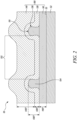
- FIG. 2 shows a schematic cross-sectional view of a portion of an article 50 in accordance with an embodiment of the present disclosure.
- the article 50 may be intended to be used in severe environmental conditions that include, for example, high temperatures and/or corrosive substances.
- the article 50 may be a part of a high-temperature mechanical system.
- One example of such high-temperature mechanical system includes a gas turbine engine, such as the gas turbine engine 10 of FIG. 1 .
- the article 50 may include a gas turbine engine component.
- the article 50 may be a component of the gas turbine engine 10 of FIG. 1 .
- the gas turbine engine component may include a seal segment, a nozzle guide vane (NGV), or any other component of the gas turbine engine 10.
- the article 50 includes a substrate 52.
- the substrate 52 may be a structural body of the article 50.
- the substrate 52 may therefore be made from any material suitable for providing structural integrity to the article 50.
- the substrate 52 may include a metal or a metal alloy.
- the substrate 52 may include, but is not limited to, nickel-based alloys, iron-nickel-based alloys, cobalt-based alloys, molybdenum-based alloys, and niobium-based alloys.
- the article 50 further includes a coating system 100.
- the coating system 100 may be disposed on the substrate 52.
- the substrate 52 may be coated with the coating system 100.
- the coating system 100 includes a bond layer 110 disposed on the article 50.
- the bond layer 110 may be disposed on the substrate 52. More specifically, the bond layer 110 may be disposed on an outer surface 53 of the substrate 52.
- the bond layer 110 includes CoNiCrAlY.
- CoNiCrAIY refers to a multi-phase polycrystalline material.
- CoNiCrAIY includes cobalt, nickel, chromium, aluminium, and yttrium.
- Co denotes cobalt
- Ni denotes nickel
- Cr denotes chromium
- Al denotes aluminium
- Y denotes yttrium.
- CoNiCrAIY may also include a trace amount of other compounds and impurities.
- the bond layer 110 may have a thickness 110T of from 100 microns to 400 microns. In some embodiments, the bond layer 110 may be substantially continuous. In some embodiments, the thickness 110T of the bond layer 110 may vary from 100 microns to 400 microns along the length and/or breadth of the substrate 52.
- the bond layer 110 may be deposited using any suitable technique, such as low-pressure plasma spraying (LPPS) (also known as vacuum plasma spraying (VPS)).
- LPPS low-pressure plasma spraying
- PVD vacuum plasma spraying
- HVOF high velocity oxyfuel
- the coating system 100 further includes a thermal barrier layer 120.
- the thermal barrier layer 120 is at least partially disposed on the bond layer 110.
- the thermal barrier layer 120 includes yttria stabilised zirconia.
- Yttria stabilized zirconia or "YSZ” refers to a ceramic that includes a cubic crystal structure of zirconium dioxide that is stabilized by addition of yttrium oxide.
- the thermal barrier layer 120 may have a thickness 120T of from 100 microns to 400 microns. In some embodiments, the thickness 120T of the thermal barrier layer 120 may vary from 100 microns to 400 microns along the length and/or breadth of the substrate 52.
- the thermal barrier layer 120 may be deposited using any suitable technique, such as air plasma spraying (APS). However, other deposition techniques may be employed to deposit the thermal barrier layer 120, and the disclosure is not limited thereto. For example, physical vapor deposition (PVD) techniques may be alternatively employed to deposit the thermal barrier layer 120.
- APS air plasma spraying
- PVD physical vapor deposition
- the coating system 100 further includes a mesh layer 130.
- the mesh layer 130 connects the thermal barrier layer 120 to the bond layer 110.
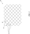
- the mesh layer 130 is also shown in FIG. 3 .
- the mesh layer 130 includes a plurality of cells 131 (only one shown in FIG. 2 ) connected to each other. Each cell 131 defines a cell opening 132 therethrough.
- the mesh layer 130 extends from the bond layer 110 and is at least partially embedded in the thermal barrier layer 120. More specifically, the cell opening 132 of each of the plurality of cells 131 at least partially receives the thermal barrier layer 120 therein.
- each of the plurality of cells 131 may include a cell wall 134.
- the cell wall 134 of each of the plurality of cells 131 may define its periphery.
- the cell wall 134 may further define the cell opening 132.
- the cell wall 134 may be shared between adjacent cells 131 from the plurality of cells 131.
- the cell opening 132 of each of the plurality of cells 131 has a rectangular, and more specifically, a square shape.
- the cell opening 132 of each of the plurality of cells 131 may have any suitable shape, such as circular, triangular, polygonal, etc., depending upon the configuration of the cell wall 134, and the disclosure is not limited thereto.
- the mesh layer 130 may have a thickness 130T of from 100 microns to 400 microns.
- the cell wall 134 may define the thickness 130T of the mesh layer 130.
- the thickness 130T of the mesh layer 130 may vary from 100 microns to 400 microns along the length and/or breadth of the substrate 52.
- the mesh layer 130 includes CoNiCrAIY.
- the mesh layer 130 may be a wire mesh. That is, the mesh layer 130 may be a wire mesh made from CoNiCrAIY, with one or more wires defining the cell walls 134 of the plurality of cells 131.
- the mesh layer 130 may be formed by deposition of CoNiCrAIY.
- the mesh layer 130 may be formed by direct laser deposition of CoNiCrAIY.
- other suitable deposition techniques may be alternatively employed to form the mesh layer 130, and the disclosure is not limited thereto.
- the mesh layer 130 may be further at least partially embedded within the bond layer 110, such that the cell opening 132 further at least partially receives the bond layer 110 therein.
- the coating system 100 further includes an abradable layer 140 disposed on the thermal barrier layer 120.
- the abradable layer 140 includes magnesium spinel.
- magnesium spinel or “MgSpinel” refers to a mineral having the composition (MgAl 2 O 4 ).
- the term “magnesium spinel” also includes magnesium-aluminium spinel, for example, having the composition MgAl (2+x) O (4+1,5x) , where x is a number from 0 to 1.
- the abradable layer 140 may have a thickness 140T of from 300 microns to 1000 microns. In some embodiments, the thickness 140T may be from 500 microns to 800 microns. In some embodiments, the thickness 140T of the abradable layer 140 may vary from 300 microns to 1000 microns along the length and/or breadth of the substrate 52.
- the abradable layer 140 may be deposited using any suitable technique, such as air plasma spraying (APS). However, other deposition techniques may be employed to deposit the abradable layer 140, and the disclosure is not limited thereto. For example, suspension plasma spraying, physical vapour deposition (PVD), cathodic arc deposition, slurry deposition, and the like may be alternatively employed to deposit the abradable layer 140.
- APS air plasma spraying
- PVD physical vapour deposition
- slurry deposition slurry deposition
- the coating system 100 may protect the substrate 52 from severe environmental conditions that include, for example, high temperatures and/or corrosive substances, and allow the article 50 to operate in the severe environmental conditions.
- the bond layer 110 may reduce or prevent formation of an oxide layer on the substrate 52. As a result, the bond layer 110 may reduce or prevent sheet spallation of the thermal barrier layer 120. Moreover, the bond layer 110 may allow creep relaxation at high temperatures. In other words, the bond layer 110 may enhance the degree of compliance between the substrate 52 and the thermal barrier layer 120, thereby reducing the risk of a strain-based failure of the coating system 100.
- the mesh layer 130 connects the thermal barrier layer 120 to the bond layer 110.
- the mesh layer 130 may function as an adhesion promoter layer between the bond layer 110 and the thermal barrier layer 120.
- the mesh layer 130 may provide a "mechanical key" between the bond layer 110 and the thermal barrier layer 120, and thus may increase robustness of the coating system 100 to strain-based failures.
- the mesh layer 130 may cause the thermal barrier layer 120 and the abradable layer 140 to crack in a localised manner. That is, local sections of the thermal barrier layer 120 and the abradable layer 140 may crack without significantly affecting adjacent local sections.
- the local sections may correspond to the mesh layer 130, and specifically to a shape of the cell openings 132 of the plurality of cells 131. Cracking of the thermal barrier layer 120 and the abradable layer 140 in such localised manner may reduce the risk of sheet strain-based failure of the coating system 100. Consequently, the abradable layer 140 may abrade or break in a controlled manner when exposed to mechanical forces of sufficient force.
- the abradable layer 140 may also thermally protect the substrate 52.
- the thermal barrier layer 120 typically has a coefficient of thermal expansion between that of the abradable layer 140, which is typically quite low, and the metallic layers (i.e., the bond layer 110 and the mesh layer 130), which is typically quite high.
- the thermal barrier layer 120 may effectively create an inter-stage between the abradable layer 140 and the metallic layers, thereby reducing relative thermal growths between them, and thus may reduce strain-based failures.
- the thermal barrier layer 120 may also assist in keeping the bond layer 110, the mesh layer 130, and the abradable layer 140 secured together.
- the abradable layer 140 and the thermal barrier layer 120 are at least partially removable from the mesh layer 130 and the bond layer 110 without damaging the mesh layer 130 and the bond layer 110.
- the abradable layer 140 and the thermal barrier layer 120 may be at least partially removable from the mesh layer 130 and the bond layer 110 by water jet stripping.
- a water jet device (not shown in FIG. 2 ) may be employed to at least partially remove the abradable layer 140 and the thermal barrier layer 120 from the mesh layer 130 and the bond layer 110.
- the water jet device may be operated with certain parameters for optimal removal of the abradable layer 140 and the thermal barrier layer 120. Such parameters will be discussed later with reference to FIG. 5 .
- the abradable layer 140 and the thermal barrier layer 120 being least partially removable from the mesh layer 130 and the bond layer 110 without damaging the mesh layer 130 and the bond layer 110 may enable repairment of the coating system 100.
- the abradable layer 140 and the thermal barrier layer 120 may be replaced with a new abradable layer and a new thermal barrier layer, respectively, to repair the coating system 100.
- the article 50 may become fit for use after repairment and thus may be reused.
- FIG. 4A shows a schematic cross-sectional view of a portion of an article 60 in accordance with another embodiment of the present disclosure.
- the article 60 is similar to the article 50 of FIG. 2 , with like elements designated by like reference characters.
- the article 60 has a different configuration of the coating system 100 as compared to the article 50 of FIG. 2 .
- the coating system 100 of the article 60 has a different configuration of the mesh layer 130 than that of FIG. 2 .
- Some elements of the coating system 100 and the article 60 are not shown in FIG. 4A for illustrative purposes.
- FIG. 4B shows a schematic zoomed-in view of a portion 69 of the article 60 in accordance with an embodiment of the present disclosure.
- the cell wall 134 may include a first portion 136 that is at least partially embedded within the bond layer 110.
- the first portion 136 may further be at least partially embedded in the thermal barrier layer 120.
- the first portion 136 may have a first maximum width 136W.
- the cell wall 134 may further include a second portion 138 that extends from the first portion 136 opposite to the bond layer 110.
- the second portion 138 may be at least partially embedded in the thermal barrier layer 120.
- the second portion 138 may have a second maximum width 138W.
- the second maximum width 138W may be greater than the first maximum width 136W.
- the second maximum width 138W may be greater than the first maximum width 136W by a factor of from 1.1 to 1.5.
- the cell wall 134 may have a minimum width 135W between the first portion 136 and the second portion 138. Moreover, as shown in FIG. 4B , in some embodiments, each of the first portion 136 and the second portion 138 may have an oval cross-sectional shape.
- the shape and dimensional configuration of the cell wall 134 may improve the connection between the bond layer 110 and the thermal barrier layer 120.
- FIG. 5 shows a flowchart depicting various steps of a method 200 for maintaining the coating system 100 on an article (e.g., the article 50 of FIG. 2 or the article 60 of FIG. 4A ) in accordance with an embodiment of the present disclosure.
- the method 200 uses a waterjet device (e.g., a water jet device 300 shown in FIG. 6 ) that includes a nozzle configured to dispense a water jet therefrom.
- the water jet device 300 includes a nozzle 310 configured to dispense a water jet 320 therefrom.
- FIG. 6 also shows x, y, and z axes.
- the method 200 will be described with additional reference to the water jet device 300 of FIG. 6 .
- the coating system 100 is shown schematically in FIG. 6 with some details omitted for illustrative purposes.
- the method 200 includes placing the article on the water jet device, such that the coating system 100 faces the nozzle. It may be noted that placing the article on the water jet device includes mounting, clamping, fastening, etc., of the article on the waterjet device.
- the water jet device may include means for allowing rotational and/or translation motion of the article with respect to the nozzle.
- the method 200 may include placing the article 50 on a table (not shown) of the water jet device 300. The table may provide rotational and/or translation motion to the article 50.
- the method 200 further includes controlling the water jet device to dispense the water jet through the nozzle, such that the water jet strikes the coating system 100.
- the waterjet has a pressure from 276 Megapascals (MPa) to 345 MPa.
- the method 200 may include controlling the waterjet device 300 to dispense the water jet 320 through the nozzle 310, such that the water jet 320 strikes the coating system 100. More specifically, the water jet 320 may strike at least the abradable layer 140 and the thermal barrier layer 120.
- the method 200 further includes controlling a movement of the article and the nozzle relative to each other, such that the abradable layer 140 and the thermal barrier layer 120 of the coating system 100 are at least partially removed from the coating system 100, and the mesh layer 130 and the bond layer 110 are at least partially exposed.
- the method 200 may include controlling a movement of the article 50 and the nozzle 310 relative to each other, such that the abradable layer 140 and the thermal barrier layer 120 of the coating system 100 are at least partially removed from the coating system 100, and the mesh layer 130 and the bond layer 110 are at least partially exposed.
- FIG. 7A shows a photograph of the article 50 with damaged or worn off thermal barrier layer 120 and abradable layer 140 (see FIG. 2 for reference).
- the method 200 may be employed to remove the damaged or worn off thermal barrier layer 120 and abradable layer 140 of the coating system 100.
- FIG. 7B shows a photograph of the article 50 after undergoing step 230 of the method 200. As shown in FIG. 7B , the mesh layer 130 and the bond layer 110 (see FIG. 2 for reference) are at least partially exposed.
- controlling the movement of the article and the nozzle relative to each other includes moving the article relative to the nozzle at a surface speed of from 13 millimetres per second (mm/s) to 70 mm/s.
- mm/s millimetres per second
- the article 50 may be moved relative to the nozzle 310 at the surface speed of from 13 mm/s to 70 mm/s substantially along the x-axis and/or the y-axis.
- controlling the movement of the article and the nozzle relative to each other further includes moving the nozzle normally to the article at a traverse speed of from 0.04 mm/s to 0.22 mm/s.
- the nozzle 310 may be moved relative to the article 50 at the traverse speed of from 0.04 mm/s to 0.22 mm/s substantially along the z-axis.
- the nozzle may extend along a nozzle axis. Further, an angle between the nozzle axis and the coating system 100 may be from 15 degrees to 45 degrees. Referring to FIG. 6 , the nozzle 310 may extend along a nozzle axis 311. An angle ⁇ between the nozzle axis 311 and the coating system 100 may be from 15 degrees to 45 degrees.
- the nozzle may be a fan jet nozzle.
- the nozzle 310 may be a fan jet nozzle.
- the nozzle may have a rotational speed of 1000 rotations per minute (RPM).
- the nozzle may rotate about the nozzle axis.
- the nozzle 310 may have a rotational speed of 1000 RPM about the nozzle axis 311.
- the nozzle may have an orifice that has a width of 0.5 millimetres.
- the nozzle 310 may have an orifice 312 that has a width 312W of 0.5 millimetres.
- the width 312W may be a maximum width of the orifice 312.
- the width 312W may correspond to a diameter of the orifice 312.
- a stand-off distance defined between the orifice of the nozzle and the article may be from 15 mm to 25 mm.
- a stand-off distance 305 defined between the orifice 312 of the nozzle 310 and the article 50 may be from 15 mm to 25 mm.
- the method 200 may further include completing two to four passes of the nozzle across the article.
- the method 200 may include completing two to four passes of the nozzle 310 across the article 50. This may ensure that the thermal barrier layer 120 and the abradable layer 140 are properly removed from the coating system 100.
- the waterjet device 300 may be operated using closed-loop process control. Alternatively, the water jet device 300 may be manually operated. The aforementioned parameters may be suitable for at least partially removing the abradable layer 140 and the thermal barrier layer 120 from the mesh layer 130 and the bond layer 110, without damaging the mesh layer 130 and the bond layer 110, by using a water jet device.
- FIG. 8A shows a schematic cross-sectional view of the article 50 after undergoing step 230 of the method 200 of FIG. 5 .
- FIG. 8B shows a schematic cross-sectional view of the article 50 that is further maintained using the method 200.
- the method 200 may further include providing a new thermal barrier layer on the exposed mesh layer and the bond layer.
- the method 200 may further include providing a new abradable layer on the new thermal barrier layer.
- the method 200 may further include providing a new thermal barrier layer 120N on the exposed mesh layer 130 and the bond layer 110.
- the method 200 may further include providing a new abradable layer 140N on the new thermal barrier layer 120N.
- the new thermal barrier layer 120N may be substantially similar to the thermal barrier layer 120 described above with reference to FIG. 2 .
- the new abradable layer 140N may be substantially similar to the abradable layer 140 described above with reference to FIG. 2 .
- Providing the new thermal barrier layer 120N and the new abradable layer 140N may effectively repair the coating system 100, such that the article 50 becomes fit for use.
- the method 200 may therefore allow repairment of the coating system 100, which may be economical as compared to scrapping the article 50 when the coating system 100 becomes damaged.
Landscapes
- Chemical & Material Sciences (AREA)
- Engineering & Computer Science (AREA)
- Ceramic Engineering (AREA)
- Materials Engineering (AREA)
- Organic Chemistry (AREA)
- Inorganic Chemistry (AREA)
- Mechanical Engineering (AREA)
- Manufacturing & Machinery (AREA)
- Structural Engineering (AREA)
- General Engineering & Computer Science (AREA)
- Chemical Kinetics & Catalysis (AREA)
- Metallurgy (AREA)
- Physics & Mathematics (AREA)
- Composite Materials (AREA)
- Plasma & Fusion (AREA)
- Thermal Sciences (AREA)
- Turbine Rotor Nozzle Sealing (AREA)
Abstract
A coating system (100) includes a bond layer (110) including CoNiCrAlY; a thermal barrier layer (120) at least partially disposed on the bond layer (110) and including yttria stabilised zirconia; a mesh layer (130) connecting the thermal barrier layer (120) to the bond layer (110) and including CoNiCrAlY; and an abradable layer (140) disposed on the thermal barrier layer (120) and including magnesium spinel. The mesh layer (130) includes a plurality of cells (131) connected to each other and is at least partially embedded in the thermal barrier layer (120). Each cell (131) defines a cell opening (132) therethrough and the cell opening (132) of each of the plurality of cells (131) at least partially receives the thermal barrier layer (120) therein. The abradable layer (140) and the thermal barrier layer (120) are at least partially removable from the mesh layer (130) and the bond layer (110) without damaging them.
Description
- The present disclosure relates to a coating system for an article (e.g. a gas turbine engine component) and a method of maintaining the coating system on the article.
- An article that is exposed to severe environmental conditions, such as those including high temperatures, corrosive substances, and the like, typically includes a coating system applied over a substrate thereof for the protection of the substrate. Such severe environmental conditions may be present in high-temperature mechanical systems, such as gas turbine engines. For example, a gas turbine engine component, such as a high-pressure seal segment and a nozzle guide vane, may include a metallic substrate and a coating system to protect the metallic substrate from oxidation and hot corrosion.
- One or more layers of the coating system may partially or fully wear away during use of the article, thereby rendering the article unsuitable for further use. A conventional coating system may be non-repairable. As a result, an article including the conventional coating system with worn away layers may need to be scrapped. Scrapping the article may be uneconomical. Thus, it may be desirable to repair a coating system that is worn instead of scrapping the article.
- Therefore, there is a need of a coating system that is suitable for use in severe environmental conditions and can be repaired when worn, and a method of maintaining or repairing the coating system.
- According to a first aspect there is provided a coating system for an article. The coating system includes a bond layer disposed on the article. The bond layer includes CoNiCrAIY. The coating system further includes a thermal barrier layer at least partially disposed on the bond layer. The thermal barrier layer includes yttria stabilised zirconia. The coating system further includes a mesh layer connecting the thermal barrier layer to the bond layer. The mesh layer includes CoNiCrAIY. The mesh layer includes a plurality of cells connected to each other. The mesh layer extends from the bond layer and is at least partially embedded in the thermal barrier layer. Each cell defines a cell opening therethrough. The cell opening of each of the plurality of cells at least partially receives the thermal barrier layer therein. The coating system further includes an abradable layer disposed on the thermal barrier layer. The abradable layer includes magnesium spinel. The abradable layer and the thermal barrier layer are at least partially removable from the mesh layer and the bond layer without damaging the mesh layer and the bond layer.
- The coating system of the present disclosure may protect a substrate of the article from severe environmental conditions that include, for example, high temperatures and/or corrosive substances, and allow the article to operate in the severe environmental conditions.
- Moreover, the coating system may be repairable. Specifically, the abradable layer and the thermal barrier layer may be replaced with a new abradable layer and a new thermal barrier layer, respectively, to repair the coating system. As a result, the article may become fit for use after repairment and thus may be reused.
- In some embodiments, the mesh layer may be a wire mesh. The wire mesh may allow the mesh layer to at least partially receive the thermal barrier layer therein.
- In some embodiments, the bond layer has a thickness of from 100 microns to 400 microns.
- In some embodiments, the mesh layer has a thickness of from 100 microns to 400 microns.
- In some embodiments, the thermal barrier layer has a thickness of from 100 microns to 400 microns.
- In some embodiments, the abradable layer has a thickness of from 300 microns to 1000 microns.
- The aforementioned dimensional ranges of various layers of the coating system may improve protection provided by the coating system while facilitating at least partial removal of the abradable layer and the thermal barrier layer from the mesh layer and the bond layer without damaging the mesh layer and the bond layer.
- In some embodiments, the abradable layer and the thermal barrier layer are at least partially removable from the mesh layer and the bond layer by water jet stripping. Water jet stripping may be advantageous over the use of chemicals and other conventional means, such as abrasive blasting and machining, for at least partial removal of the abradable layer and the thermal barrier layer from the mesh layer and the bond layer. Moreover, certain water stripping parameters disclosed herein may be used to improve the efficiency of water jet stripping.
- In some embodiments, each of the plurality of cells includes a cell wall. The cell wall includes a first portion that is at least partially embedded within the bond layer. The first portion has a first maximum width. The cell wall further includes a second portion that extends from the first portion opposite to the bond layer. The second portion is at least partially embedded in the thermal barrier layer. The second portion has a second maximum width. The second maximum width is greater than the first maximum width.
- In some embodiments, each of the first portion and the second portion has an oval cross-sectional shape.
- In some embodiments, the cell wall has a minimum width between the first portion and the second portion.
- The aforementioned shape and dimensional configuration of the cell wall may improve the connection between the bond layer and the thermal barrier layer.
- In some embodiments, the cell opening of each of the plurality of cells further at least partially receives the bond layer therein.
- Therefore, the cell opening of each of the plurality of cells at least partially receives both the bond layer and the thermal barrier layer therein, thereby improving the connection between the bond layer and the thermal barrier layer.
- According to a second aspect there is provided an article. The article includes a substrate. The article further includes the coating system of the first aspect.
- The substrate of the article may be protected from severe environmental conditions that include, for example, high temperatures and/or corrosive substances by the coating system. Therefore, the article may be suitable for operation in the severe environmental conditions. Advantageously, after undergoing operational wear and tear, the coating system may be repaired, and the article may be suitable for use again.
- In some embodiments, the article is a gas turbine engine component.
- According to a third aspect there is provided a method for maintaining the coating system of the first aspect on an article using a water jet device that includes a nozzle configured to dispense a waterjet therefrom. The method includes placing the article on the waterjet device, such that the coating system faces the nozzle. The method further includes controlling the water jet device to dispense the water jet through the nozzle, such that the water jet strikes the coating system. The water jet has a pressure from 276 Megapascals (MPa) to 345 MPa. The method further includes controlling a movement of the article and the nozzle relative to each other, such that the abradable layer and the thermal barrier layer of the coating system are at least partially removed from the coating system, and the mesh layer and the bond layer are at least partially exposed.
- The method of the present disclosure may at least partially remove the abradable layer and the thermal barrier from the coating system using water jet stripping, such that the mesh layer and the bond layer are at least partially exposed. This may allow application of replacement abradable and thermal barrier layers to repair the coating system.
- In some embodiments, controlling the movement of the article and the nozzle relative to each other comprises moving the article relative to the nozzle at a surface speed of from 13 millimetres per second (mm/s) to 70 mm/s.
- In some embodiments, controlling the movement of the article and the nozzle relative to each other further comprises moving the nozzle normally to the article at a traverse speed of from 0.04 mm/s to 0.22 mm/s.
- In some embodiments, the nozzle extends along a nozzle axis, and wherein an angle between the nozzle axis and the coating system is from 15 degrees to 45 degrees.
- In some embodiments, the nozzle is a fan jet nozzle.
- In some embodiments, wherein the nozzle has a rotational speed of 1000 rotations per minute (RPM).
- In some embodiments, the nozzle has an orifice that has a width of 0.5 millimetres.
- In some embodiments, a stand-off distance defined between the orifice of the nozzle and the article is from 15 mm to 25 mm.
- In some embodiments, the method further includes completing two to four passes of the nozzle across the article.
- The aforementioned parameters may be suitable for at least partially removing the abradable layer and the thermal barrier layer from the mesh layer and the bond layer without damaging the mesh layer and the bond layer using the water jet device.
- In some embodiments, the method further includes providing a new thermal barrier layer on the exposed mesh layer and the bond layer. The method further includes providing a new abradable layer on the new thermal barrier layer.
- Providing the new thermal barrier layer and the new abradable layer may effectively repair the coating system, such that the article becomes fit for use. The method may therefore allow repairment of the coating system, which may be economical as compared to scrapping the article when the coating system becomes damaged.
- As noted elsewhere herein, the present disclosure may relate to a gas turbine engine. Such a gas turbine engine may comprise an engine core comprising a turbine, a combustor, a compressor, and a core shaft connecting the turbine to the compressor. Such a gas turbine engine may comprise a fan (having fan blades) located upstream of the engine core.
- Arrangements of the present disclosure may be particularly, although not exclusively, beneficial for fans that are driven via a gearbox. Accordingly, the gas turbine engine may comprise a gearbox that receives an input from the core shaft and outputs drive to the fan so as to drive the fan at a lower rotational speed than the core shaft. The input to the gearbox may be directly from the core shaft, or indirectly from the core shaft, for example via a spur shaft and/or gear. The core shaft may rigidly connect the turbine and the compressor, such that the turbine and compressor rotate at the same speed (with the fan rotating at a lower speed). The gearbox may be a reduction gearbox (in that the output to the fan is a lower rotational rate than the input from the core shaft). Any type of gearbox may be used.
- The gas turbine engine as described and/or claimed herein may have any suitable general architecture. For example, the gas turbine engine may have any desired number of shafts that connect turbines and compressors, for example one, two or three shafts. Purely by way of example, the turbine connected to the core shaft may be a first turbine, the compressor connected to the core shaft may be a first compressor, and the core shaft may be a first core shaft. The engine core may further comprise a second turbine, a second compressor, and a second core shaft connecting the second turbine to the second compressor. The second turbine, second compressor, and second core shaft may be arranged to rotate at a higher rotational speed than the first core shaft.
- In such an arrangement, the second compressor may be positioned axially downstream of the first compressor. The second compressor may be arranged to receive (for example directly receive, for example via a generally annular duct) flow from the first compressor.
- In any gas turbine engine as described and/or claimed herein, a combustor may be provided axially downstream of the fan and compressor(s). For example, the combustor may be directly downstream of (for example at the exit of) the second compressor, where a second compressor is provided. By way of further example, the flow at the exit to the combustor may be provided to the inlet of the second turbine, where a second turbine is provided. The combustor may be provided upstream of the turbine(s).
- The or each compressor (for example the first compressor and second compressor as described above) may comprise any number of stages, for example multiple stages. Each stage may comprise a row of rotor blades and a row of stator vanes, which may be variable stator vanes (in that their angle of incidence may be variable). The row of rotor blades and the row of stator vanes may be axially offset from each other.
- The or each turbine (for example the first turbine and second turbine as described above) may comprise any number of stages, for example multiple stages. Each stage may comprise a row of rotor blades and a row of stator vanes. The row of rotor blades and the row of stator vanes may be axially offset from each other.
- Gas turbine engines in accordance with the present disclosure may have any desired bypass ratio, where the bypass ratio is defined as the ratio of the mass flow rate of the flow through the bypass duct to the mass flow rate of the flow through the core at cruise conditions. The bypass duct may be substantially annular. The bypass duct may be radially outside the engine core. The radially outer surface of the bypass duct may be defined by a nacelle and/or a fan case.
- Specific thrust of an engine may be defined as the net thrust of the engine divided by the total mass flow through the engine. At cruise conditions, the specific thrust of an engine described and/or claimed herein may be less than (or on the order of) any of the following: 110 Nkg-1s, 105 Nkg-1s, 100 Nkg-1s, 95 Nkg-1s, 90 Nkg-1s, 85 Nkg-1s or 80 Nkg-1s. The specific thrust may be in an inclusive range bounded by any two of the values in the previous sentence (i.e., the values may form upper or lower bounds), for example in the range of from 80 Nkg-1s to 100 Nkg-1s, or 85 Nkg-1s to 95 Nkg-1s. Such engines may be particularly efficient in comparison with conventional gas turbine engines.
- A fan blade and/or aerofoil portion of a fan blade described and/or claimed herein may be manufactured from any suitable material or combination of materials. For example, at least a part of the fan blade and/or aerofoil may be manufactured at least in part from a composite, for example a metal matrix composite and/or an organic matrix composite, such as carbon fibre.
- The fan of a gas turbine as described and/or claimed herein may have any desired number of fan blades, for example 14, 16, 18, 20, 22, 24 or 26 fan blades.
- The skilled person will appreciate that except where mutually exclusive, a feature or parameter described in relation to any one of the above aspects may be applied to any other aspect. Furthermore, except where mutually exclusive, any feature or parameter described herein may be applied to any aspect and/or combined with any other feature or parameter described herein.
- Embodiments will now be described by way of example only, with reference to the Figures, in which:
-
FIG. 1 is a sectional side view of a gas turbine engine; -
FIG. 2 is a schematic cross-sectional view of a portion of an article including a coating system in accordance with an embodiment of the present disclosure; -
FIG. 3 is a schematic plan view of a portion of a mesh layer of the coating system in accordance with an embodiment of the present disclosure; -
FIG. 4A is a schematic cross-sectional view of a portion of an article in accordance with another embodiment of the present disclosure with some elements of the coating system not shown; -
FIG. 4B is a schematic zoomed-in view of a portion of the article ofFIG. 4A in accordance with an embodiment of the present disclosure; -
FIG. 5 is a flowchart depicting various steps of a method for maintaining the coating system on an article in accordance with an embodiment of the present disclosure; -
FIG. 6 is a schematic diagram of a water jet device for performing the method ofFIG. 5 in accordance with an embodiment of the present disclosure; -
FIG. 7A is a photograph showing a plan view of an article with a worn off coating system in accordance with an embodiment of the present disclosure; -
FIG. 7B is a photograph showing a plan view of the article ofFIG. 7A after undergoing the method ofFIG. 5 in accordance with an embodiment of the present disclosure; -
FIG. 8A is a schematic cross-sectional view of an article after undergoing the method ofFIG. 5 in accordance with an embodiment of the present disclosure; and -
FIG. 8B is a schematic cross-sectional view of the article ofFIG. 8A after undergoing further steps of the method ofFIG. 5 in accordance with an embodiment of the present disclosure. - The following table lists the reference numerals used in the drawings with the features to which they refer:
Ref no. Feature FIG. 9 Principal and rotational axis 1 10 Gas turbine engine 1 11 Core 1 12 Air intake 1 14 Low pressure compressor 1 15 High pressure compressor 1 16 Combustion equipment 1 17 High pressure turbine 1 18 Bypass exhaust nozzle 1 19 Low pressure turbine 1 20 Core exhaust nozzle 1 21 Nacelle 1 22 Bypass duct 1 23 Propulsive fan 1 26 Shaft 1 27 Interconnecting shaft 1 30 Epicyclic gearbox 1 50 Article 2 6 7A 7B 8A 8B 52 Substrate 2 6 8A 53 Outer surface (of substrate) 2 60 Article 4A 69 Portion (of article) 4A 100 Coating system 2 4A 6 8B 110 Bond layer 2 4A 4B 6 8A 8B 110T Thickness 2 120 Thermal barrier layer 2 4A 4B 6 120N New thermal barrier layer 8B Ref no. Feature FIG. 120T Thickness (of thermal barrier layer) 2 130 Mesh layer 2 3 6 8A 8B 130T Thickness (of mesh layer) 2 131 Cell(s) (of mesh layer) 23 132 Cell opening 234A 134 Cell wall 234A 135W Minimum width (of cell wall) 4B 136 First portion (of cell wall) 4B 136W First maximum width 4B 138 Second portion (of cell wall) 4B 138W Second maximum width 4B 140 Abradable layer 26 140N New abradable layer 8B 140T Thickness (of abradable layer) 2 200 Method 5 210 Step 5 220 Step 5 230 Step 5 300 Water jet device 6 305 Stand-off distance 6 310 Nozzle 6 311 Nozzle axis 6 312 Orifice 6 312W Width (of orifice) 6 320 Water jet 6 α Angle 6 A Core airflow 1 B Bypass airflow 1 x Axis 6 y Axis 6 z Axis 6 - Aspects and embodiments of the present disclosure will now be discussed with reference to the accompanying figures. Further aspects and embodiments will be apparent to those skilled in the art.
-
FIG. 1 illustrates agas turbine engine 10 having a principal androtational axis 9. Theengine 10 comprises anair intake 12 and apropulsive fan 23 that generates two airflows: a core airflow A and a bypass airflow B. Thegas turbine engine 10 comprises anengine core 11 that receives the core airflow A. Theengine core 11 comprises, in axial flow series, alow pressure compressor 14, ahigh pressure compressor 15,combustion equipment 16, ahigh pressure turbine 17, alow pressure turbine 19, and acore exhaust nozzle 20. Anacelle 21 surrounds thegas turbine engine 10 and defines abypass duct 22 and abypass exhaust nozzle 18. The bypass airflow B flows through thebypass duct 22. Thefan 23 is attached to and driven by thelow pressure turbine 19 via ashaft 26 and anepicyclic gearbox 30. - In use, the core airflow A is accelerated and compressed by the
low pressure compressor 14 and directed into thehigh pressure compressor 15 where further compression takes place. The compressed air exhausted from thehigh pressure compressor 15 is directed into thecombustion equipment 16 where it is mixed with fuel and the mixture is combusted. The resultant hot combustion products then expand through, and thereby drive, the high pressure andlow pressure turbines core exhaust nozzle 20 to provide some propulsive thrust. Thehigh pressure turbine 17 drives thehigh pressure compressor 15 by a suitable interconnectingshaft 27. Thefan 23 generally provides the majority of the propulsive thrust. Theepicyclic gearbox 30 is a reduction gearbox. - Note that the terms "low pressure turbine" and "low pressure compressor" as used herein may be taken to mean the lowest pressure turbine stages and lowest pressure compressor stages (i.e., not including the fan 23) respectively and/or the turbine and compressor stages that are connected together by the interconnecting
shaft 26 with the lowest rotational speed in the engine (i.e., not including the gearbox output shaft that drives the fan 23). In some literature, the "low pressure turbine" and "low pressure compressor" referred to herein may alternatively be known as the "intermediate pressure turbine" and "intermediate pressure compressor". Where such alternative nomenclature is used, thefan 23 may be referred to as a first, or lowest pressure, compression stage. - Other gas turbine engines to which the present disclosure may be applied may have alternative configurations. For example, such engines may have an alternative number of compressors and/or turbines and/or an alternative number of interconnecting shafts. By way of further example, the
gas turbine engine 10 shown inFIG. 1 has asplit flow nozzle bypass duct 22 has itsown nozzle 18 that is separate to and radially outside thecore exhaust nozzle 20. However, this is not limiting, and any aspect of the present disclosure may also apply to engines in which the flow through thebypass duct 22 and the flow through the core 11 are mixed, or combined, before (or upstream of) a single nozzle, which may be referred to as a mixed flow nozzle. One or both nozzles (whether mixed or split flow) may have a fixed or variable area. Whilst the described example relates to a turbofan engine, the disclosure may apply, for example, to any type of gas turbine engine, such as an open rotor (in which the fan stage is not surrounded by a nacelle) or turboprop engine, for example. In some arrangements, thegas turbine engine 10 may not comprise agearbox 30. - The geometry of the
gas turbine engine 10, and components thereof, is defined by a conventional axis system, comprising an axial direction (which is aligned with the rotational axis 9), a radial direction (in the bottom-to-top direction inFIG. 1 ), and a circumferential direction (perpendicular to the page in theFIG. 1 view). The axial, radial, and circumferential directions are mutually perpendicular. -
FIG. 2 shows a schematic cross-sectional view of a portion of anarticle 50 in accordance with an embodiment of the present disclosure. - The
article 50 may be intended to be used in severe environmental conditions that include, for example, high temperatures and/or corrosive substances. In some examples, thearticle 50 may be a part of a high-temperature mechanical system. One example of such high-temperature mechanical system includes a gas turbine engine, such as thegas turbine engine 10 ofFIG. 1 . In some embodiments, thearticle 50 may include a gas turbine engine component. For example, thearticle 50 may be a component of thegas turbine engine 10 ofFIG. 1 . The gas turbine engine component may include a seal segment, a nozzle guide vane (NGV), or any other component of thegas turbine engine 10. - The
article 50 includes asubstrate 52. Thesubstrate 52 may be a structural body of thearticle 50. Thesubstrate 52 may therefore be made from any material suitable for providing structural integrity to thearticle 50. In some embodiments, thesubstrate 52 may include a metal or a metal alloy. Thesubstrate 52 may include, but is not limited to, nickel-based alloys, iron-nickel-based alloys, cobalt-based alloys, molybdenum-based alloys, and niobium-based alloys. - The
article 50 further includes acoating system 100. Thecoating system 100 may be disposed on thesubstrate 52. In other words, thesubstrate 52 may be coated with thecoating system 100. - The
coating system 100 includes abond layer 110 disposed on thearticle 50. Specifically, thebond layer 110 may be disposed on thesubstrate 52. More specifically, thebond layer 110 may be disposed on anouter surface 53 of thesubstrate 52. Thebond layer 110 includes CoNiCrAlY. As used in the present disclosure, the term "CoNiCrAIY" refers to a multi-phase polycrystalline material. CoNiCrAIY includes cobalt, nickel, chromium, aluminium, and yttrium. "Co" denotes cobalt, "Ni" denotes nickel, "Cr" denotes chromium, "Al" denotes aluminium, and "Y" denotes yttrium. CoNiCrAIY may also include a trace amount of other compounds and impurities. - The
bond layer 110 may have athickness 110T of from 100 microns to 400 microns. In some embodiments, thebond layer 110 may be substantially continuous. In some embodiments, thethickness 110T of thebond layer 110 may vary from 100 microns to 400 microns along the length and/or breadth of thesubstrate 52. - The
bond layer 110 may be deposited using any suitable technique, such as low-pressure plasma spraying (LPPS) (also known as vacuum plasma spraying (VPS)). However, other deposition techniques may be employed to deposit thebond layer 110, and the disclosure is not limited thereto. For example, sputtering flame spray, physical vapour deposition (PVD), high velocity oxyfuel (HVOF) spraying, and the like, may be alternatively employed to deposit thebond layer 110. - The
coating system 100 further includes athermal barrier layer 120. Thethermal barrier layer 120 is at least partially disposed on thebond layer 110. Thethermal barrier layer 120 includes yttria stabilised zirconia. As used in the present disclosure, the term "Yttria stabilized zirconia" or "YSZ" refers to a ceramic that includes a cubic crystal structure of zirconium dioxide that is stabilized by addition of yttrium oxide. - The
thermal barrier layer 120 may have a thickness 120T of from 100 microns to 400 microns. In some embodiments, the thickness 120T of thethermal barrier layer 120 may vary from 100 microns to 400 microns along the length and/or breadth of thesubstrate 52. - The
thermal barrier layer 120 may be deposited using any suitable technique, such as air plasma spraying (APS). However, other deposition techniques may be employed to deposit thethermal barrier layer 120, and the disclosure is not limited thereto. For example, physical vapor deposition (PVD) techniques may be alternatively employed to deposit thethermal barrier layer 120. - The
coating system 100 further includes amesh layer 130. Themesh layer 130 connects thethermal barrier layer 120 to thebond layer 110. Themesh layer 130 is also shown inFIG. 3 . Themesh layer 130 includes a plurality of cells 131 (only one shown inFIG. 2 ) connected to each other. Eachcell 131 defines acell opening 132 therethrough. - The
mesh layer 130 extends from thebond layer 110 and is at least partially embedded in thethermal barrier layer 120. More specifically, thecell opening 132 of each of the plurality ofcells 131 at least partially receives thethermal barrier layer 120 therein. - Referring to
FIGS. 2 and3 , each of the plurality ofcells 131 may include acell wall 134. Thecell wall 134 of each of the plurality ofcells 131 may define its periphery. Thecell wall 134 may further define thecell opening 132. It may be noted that thecell wall 134 may be shared betweenadjacent cells 131 from the plurality ofcells 131. In the illustrated embodiment ofFIG. 3 , thecell opening 132 of each of the plurality ofcells 131 has a rectangular, and more specifically, a square shape. However, it may be noted that thecell opening 132 of each of the plurality ofcells 131 may have any suitable shape, such as circular, triangular, polygonal, etc., depending upon the configuration of thecell wall 134, and the disclosure is not limited thereto. - The
mesh layer 130 may have athickness 130T of from 100 microns to 400 microns. Thecell wall 134 may define thethickness 130T of themesh layer 130. In some embodiments, thethickness 130T of themesh layer 130 may vary from 100 microns to 400 microns along the length and/or breadth of thesubstrate 52. - The
mesh layer 130 includes CoNiCrAIY. In some embodiments, themesh layer 130 may be a wire mesh. That is, themesh layer 130 may be a wire mesh made from CoNiCrAIY, with one or more wires defining thecell walls 134 of the plurality ofcells 131. In some other embodiments, themesh layer 130 may be formed by deposition of CoNiCrAIY. In some embodiments, themesh layer 130 may be formed by direct laser deposition of CoNiCrAIY. However, other suitable deposition techniques may be alternatively employed to form themesh layer 130, and the disclosure is not limited thereto. - While not illustrated in
FIG. 2 , in some embodiments, themesh layer 130 may be further at least partially embedded within thebond layer 110, such that thecell opening 132 further at least partially receives thebond layer 110 therein. - The
coating system 100 further includes anabradable layer 140 disposed on thethermal barrier layer 120. Theabradable layer 140 includes magnesium spinel. As used in the present disclosure, the term "magnesium spinel" or "MgSpinel" refers to a mineral having the composition (MgAl2O4). The term "magnesium spinel" also includes magnesium-aluminium spinel, for example, having the composition MgAl(2+x)O(4+1,5x), where x is a number from 0 to 1. - The
abradable layer 140 may have athickness 140T of from 300 microns to 1000 microns. In some embodiments, thethickness 140T may be from 500 microns to 800 microns. In some embodiments, thethickness 140T of theabradable layer 140 may vary from 300 microns to 1000 microns along the length and/or breadth of thesubstrate 52. - The
abradable layer 140 may be deposited using any suitable technique, such as air plasma spraying (APS). However, other deposition techniques may be employed to deposit theabradable layer 140, and the disclosure is not limited thereto. For example, suspension plasma spraying, physical vapour deposition (PVD), cathodic arc deposition, slurry deposition, and the like may be alternatively employed to deposit theabradable layer 140. - The
coating system 100 may protect thesubstrate 52 from severe environmental conditions that include, for example, high temperatures and/or corrosive substances, and allow thearticle 50 to operate in the severe environmental conditions. - Specifically, the
bond layer 110 may reduce or prevent formation of an oxide layer on thesubstrate 52. As a result, thebond layer 110 may reduce or prevent sheet spallation of thethermal barrier layer 120. Moreover, thebond layer 110 may allow creep relaxation at high temperatures. In other words, thebond layer 110 may enhance the degree of compliance between thesubstrate 52 and thethermal barrier layer 120, thereby reducing the risk of a strain-based failure of thecoating system 100. - As discussed above, the
mesh layer 130 connects thethermal barrier layer 120 to thebond layer 110. Themesh layer 130 may function as an adhesion promoter layer between thebond layer 110 and thethermal barrier layer 120. Specifically, themesh layer 130 may provide a "mechanical key" between thebond layer 110 and thethermal barrier layer 120, and thus may increase robustness of thecoating system 100 to strain-based failures. - Moreover, the
mesh layer 130 may cause thethermal barrier layer 120 and theabradable layer 140 to crack in a localised manner. That is, local sections of thethermal barrier layer 120 and theabradable layer 140 may crack without significantly affecting adjacent local sections. The local sections may correspond to themesh layer 130, and specifically to a shape of thecell openings 132 of the plurality ofcells 131. Cracking of thethermal barrier layer 120 and theabradable layer 140 in such localised manner may reduce the risk of sheet strain-based failure of thecoating system 100. Consequently, theabradable layer 140 may abrade or break in a controlled manner when exposed to mechanical forces of sufficient force. Theabradable layer 140 may also thermally protect thesubstrate 52. - The
thermal barrier layer 120 typically has a coefficient of thermal expansion between that of theabradable layer 140, which is typically quite low, and the metallic layers (i.e., thebond layer 110 and the mesh layer 130), which is typically quite high. Thethermal barrier layer 120 may effectively create an inter-stage between theabradable layer 140 and the metallic layers, thereby reducing relative thermal growths between them, and thus may reduce strain-based failures. Thethermal barrier layer 120 may also assist in keeping thebond layer 110, themesh layer 130, and theabradable layer 140 secured together. - The
abradable layer 140 and thethermal barrier layer 120 are at least partially removable from themesh layer 130 and thebond layer 110 without damaging themesh layer 130 and thebond layer 110. In some embodiments, theabradable layer 140 and thethermal barrier layer 120 may be at least partially removable from themesh layer 130 and thebond layer 110 by water jet stripping. For example, a water jet device (not shown inFIG. 2 ) may be employed to at least partially remove theabradable layer 140 and thethermal barrier layer 120 from themesh layer 130 and thebond layer 110. The water jet device may be operated with certain parameters for optimal removal of theabradable layer 140 and thethermal barrier layer 120. Such parameters will be discussed later with reference toFIG. 5 . - The
abradable layer 140 and thethermal barrier layer 120 being least partially removable from themesh layer 130 and thebond layer 110 without damaging themesh layer 130 and thebond layer 110 may enable repairment of thecoating system 100. Specifically, theabradable layer 140 and thethermal barrier layer 120 may be replaced with a new abradable layer and a new thermal barrier layer, respectively, to repair thecoating system 100. As a result, thearticle 50 may become fit for use after repairment and thus may be reused. -
FIG. 4A shows a schematic cross-sectional view of a portion of anarticle 60 in accordance with another embodiment of the present disclosure. Thearticle 60 is similar to thearticle 50 ofFIG. 2 , with like elements designated by like reference characters. However, thearticle 60 has a different configuration of thecoating system 100 as compared to thearticle 50 ofFIG. 2 . Specifically, thecoating system 100 of thearticle 60 has a different configuration of themesh layer 130 than that ofFIG. 2 . Some elements of thecoating system 100 and thearticle 60 are not shown inFIG. 4A for illustrative purposes. -
FIG. 4B shows a schematic zoomed-in view of aportion 69 of thearticle 60 in accordance with an embodiment of the present disclosure. - Referring to
FIGS. 4A and 4B , in some embodiments, thecell wall 134 may include afirst portion 136 that is at least partially embedded within thebond layer 110. In some embodiments, as shown inFIG. 4B , thefirst portion 136 may further be at least partially embedded in thethermal barrier layer 120. Thefirst portion 136 may have a firstmaximum width 136W. - The
cell wall 134 may further include asecond portion 138 that extends from thefirst portion 136 opposite to thebond layer 110. Thesecond portion 138 may be at least partially embedded in thethermal barrier layer 120. Thesecond portion 138 may have a secondmaximum width 138W. The secondmaximum width 138W may be greater than the firstmaximum width 136W. In some embodiments, the secondmaximum width 138W may be greater than the firstmaximum width 136W by a factor of from 1.1 to 1.5. - In some embodiments, the
cell wall 134 may have aminimum width 135W between thefirst portion 136 and thesecond portion 138. Moreover, as shown inFIG. 4B , in some embodiments, each of thefirst portion 136 and thesecond portion 138 may have an oval cross-sectional shape. - The shape and dimensional configuration of the
cell wall 134, as shown inFIGS. 4A and 4B , may improve the connection between thebond layer 110 and thethermal barrier layer 120. -
FIG. 5 shows a flowchart depicting various steps of amethod 200 for maintaining thecoating system 100 on an article (e.g., thearticle 50 ofFIG. 2 or thearticle 60 ofFIG. 4A ) in accordance with an embodiment of the present disclosure. Themethod 200 uses a waterjet device (e.g., awater jet device 300 shown inFIG. 6 ) that includes a nozzle configured to dispense a water jet therefrom. Thewater jet device 300 includes anozzle 310 configured to dispense awater jet 320 therefrom.FIG. 6 also shows x, y, and z axes. Themethod 200 will be described with additional reference to thewater jet device 300 ofFIG. 6 . Thecoating system 100 is shown schematically inFIG. 6 with some details omitted for illustrative purposes. - At
step 210, themethod 200 includes placing the article on the water jet device, such that thecoating system 100 faces the nozzle. It may be noted that placing the article on the water jet device includes mounting, clamping, fastening, etc., of the article on the waterjet device. The water jet device may include means for allowing rotational and/or translation motion of the article with respect to the nozzle. Referring toFIG. 6 , themethod 200 may include placing thearticle 50 on a table (not shown) of thewater jet device 300. The table may provide rotational and/or translation motion to thearticle 50. - At
step 220, themethod 200 further includes controlling the water jet device to dispense the water jet through the nozzle, such that the water jet strikes thecoating system 100. The waterjet has a pressure from 276 Megapascals (MPa) to 345 MPa. For example, referring toFIG. 6 , themethod 200 may include controlling thewaterjet device 300 to dispense thewater jet 320 through thenozzle 310, such that thewater jet 320 strikes thecoating system 100. More specifically, thewater jet 320 may strike at least theabradable layer 140 and thethermal barrier layer 120. - At
step 230, themethod 200 further includes controlling a movement of the article and the nozzle relative to each other, such that theabradable layer 140 and thethermal barrier layer 120 of thecoating system 100 are at least partially removed from thecoating system 100, and themesh layer 130 and thebond layer 110 are at least partially exposed. Referring toFIG. 6 , for example, themethod 200 may include controlling a movement of thearticle 50 and thenozzle 310 relative to each other, such that theabradable layer 140 and thethermal barrier layer 120 of thecoating system 100 are at least partially removed from thecoating system 100, and themesh layer 130 and thebond layer 110 are at least partially exposed. -
FIG. 7A shows a photograph of thearticle 50 with damaged or worn offthermal barrier layer 120 and abradable layer 140 (seeFIG. 2 for reference). Themethod 200 may be employed to remove the damaged or worn offthermal barrier layer 120 andabradable layer 140 of thecoating system 100. -
FIG. 7B shows a photograph of thearticle 50 after undergoingstep 230 of themethod 200. As shown inFIG. 7B , themesh layer 130 and the bond layer 110 (seeFIG. 2 for reference) are at least partially exposed. - In some embodiments, controlling the movement of the article and the nozzle relative to each other includes moving the article relative to the nozzle at a surface speed of from 13 millimetres per second (mm/s) to 70 mm/s. Referring to
FIG. 6 , for example, thearticle 50 may be moved relative to thenozzle 310 at the surface speed of from 13 mm/s to 70 mm/s substantially along the x-axis and/or the y-axis. - In some embodiments, controlling the movement of the article and the nozzle relative to each other further includes moving the nozzle normally to the article at a traverse speed of from 0.04 mm/s to 0.22 mm/s. Referring to
FIG. 6 , for example, thenozzle 310 may be moved relative to thearticle 50 at the traverse speed of from 0.04 mm/s to 0.22 mm/s substantially along the z-axis. - In some embodiments, the nozzle may extend along a nozzle axis. Further, an angle between the nozzle axis and the
coating system 100 may be from 15 degrees to 45 degrees. Referring toFIG. 6 , thenozzle 310 may extend along anozzle axis 311. An angle α between thenozzle axis 311 and thecoating system 100 may be from 15 degrees to 45 degrees. - In some embodiments, the nozzle may be a fan jet nozzle. Referring to
FIG. 6 , for example, thenozzle 310 may be a fan jet nozzle. - In some embodiments, the nozzle may have a rotational speed of 1000 rotations per minute (RPM). The nozzle may rotate about the nozzle axis. Referring to
FIG. 6 , for example, thenozzle 310 may have a rotational speed of 1000 RPM about thenozzle axis 311. - In some embodiments, the nozzle may have an orifice that has a width of 0.5 millimetres. For example, the
nozzle 310 may have anorifice 312 that has awidth 312W of 0.5 millimetres. Thewidth 312W may be a maximum width of theorifice 312. In some embodiments, thewidth 312W may correspond to a diameter of theorifice 312. - In some embodiments, a stand-off distance defined between the orifice of the nozzle and the article may be from 15 mm to 25 mm. Referring to
FIG. 6 , for example, a stand-off distance 305 defined between theorifice 312 of thenozzle 310 and thearticle 50 may be from 15 mm to 25 mm. - In some embodiments, the
method 200 may further include completing two to four passes of the nozzle across the article. For example, themethod 200 may include completing two to four passes of thenozzle 310 across thearticle 50. This may ensure that thethermal barrier layer 120 and theabradable layer 140 are properly removed from thecoating system 100. - In some embodiments, the
waterjet device 300 may be operated using closed-loop process control. Alternatively, thewater jet device 300 may be manually operated. The aforementioned parameters may be suitable for at least partially removing theabradable layer 140 and thethermal barrier layer 120 from themesh layer 130 and thebond layer 110, without damaging themesh layer 130 and thebond layer 110, by using a water jet device. -
FIG. 8A shows a schematic cross-sectional view of thearticle 50 after undergoingstep 230 of themethod 200 ofFIG. 5 . -
FIG. 8B shows a schematic cross-sectional view of thearticle 50 that is further maintained using themethod 200. - As shown in
FIG. 8A , after performance ofstep 230 on thearticle 50, themesh layer 130 and thebond layer 110 may be at least partially exposed. Referring toFIGS. 5 ,6 ,8A, and 8B , in some embodiments, themethod 200 may further include providing a new thermal barrier layer on the exposed mesh layer and the bond layer. Themethod 200 may further include providing a new abradable layer on the new thermal barrier layer. For example, as shown inFIG. 8B , themethod 200 may further include providing a newthermal barrier layer 120N on the exposedmesh layer 130 and thebond layer 110. Themethod 200 may further include providing a newabradable layer 140N on the newthermal barrier layer 120N. The newthermal barrier layer 120N may be substantially similar to thethermal barrier layer 120 described above with reference toFIG. 2 . The newabradable layer 140N may be substantially similar to theabradable layer 140 described above with reference toFIG. 2 . - Providing the new
thermal barrier layer 120N and the newabradable layer 140N may effectively repair thecoating system 100, such that thearticle 50 becomes fit for use. Themethod 200 may therefore allow repairment of thecoating system 100, which may be economical as compared to scrapping thearticle 50 when thecoating system 100 becomes damaged.
Claims (15)
- A coating system (100) for an article (50), the coating system (100) comprising:a bond layer (110) disposed on the article (50) and comprising CoNiCrAlY;a thermal barrier layer (120) at least partially disposed on the bond layer (110), the thermal barrier layer (120) comprising yttria stabilised zirconia;a mesh layer (130) connecting the thermal barrier layer (120) to the bond layer (110), the mesh layer (130) comprising CoNiCrAlY, wherein the mesh layer (130) comprises a plurality of cells (131) connected to each other, wherein the mesh layer (130) extends from the bond layer (110) and is at least partially embedded in the thermal barrier layer (120), wherein each cell (131) defines a cell opening (132) therethrough, and wherein the cell opening (132) of each of the plurality of cells (131) at least partially receives the thermal barrier layer (120) therein; andan abradable layer (140) disposed on the thermal barrier layer (120) and comprising magnesium spinel;wherein the abradable layer (140) and the thermal barrier layer (120) are at least partially removable from the mesh layer (130) and the bond layer (110) without damaging the mesh layer (130) and the bond layer (110).
- The coating system (100) of claim 1, wherein the bond layer (110) has a thickness (110T) of from 100 microns to 400 microns.
- The coating system (100) of claim 1 or 2, wherein the mesh layer (130) has a thickness (130T) of from 100 microns to 400 microns.
- The coating system (100) of any preceding claim, wherein the thermal barrier layer (120) has a thickness (120T) of from 100 microns to 400 microns.
- The coating system (100) of any preceding claim, wherein the abradable layer (140) has a thickness (140T) of from 300 microns to 1000 microns.
- The coating system (100) of any preceding claim, wherein the abradable layer (140) and the thermal barrier layer (120) are at least partially removable from the mesh layer (130) and the bond layer (110) by water jet stripping.
- The coating system (100) of any preceding claim, wherein each of the plurality of cells (131) comprises a cell wall (134), the cell wall (134) comprising:a first portion (136) that is at least partially embedded within the bond layer (110), the first portion (136) having a first maximum width (136W); anda second portion (138) that extends from the first portion (136) opposite to the bond layer (110) and is at least partially embedded in the thermal barrier layer (120), the second portion (138) having a second maximum width (138W), wherein the second maximum width (138W) is greater than the first maximum width (136W).
- The coating system (100) of claim 7, wherein each of the first portion (136) and the second portion (138) has an oval cross-sectional shape.
- The coating system (100) of claim 7 or 8, wherein the cell wall (134) has a minimum width (135W) between the first portion (136) and the second portion (138).
- The coating system (100) of any preceding claim, wherein the cell opening (132) of each of the plurality of cells (131) further at least partially receives the bond layer (110) therein.
- An article (50) comprising:a substrate (52); andthe coating system (100) of any preceding claim.
- The article (50) of claim 11, wherein the article (50) is a gas turbine engine component.
- A method (200) for maintaining the coating system of any one of claims 1 to 10 on an article (50) using a water jet device (300) that includes a nozzle (310) configured to dispense a water jet (320) therefrom, the method (200) comprising the steps of:placing the article (50) on the waterjet device (300), such that the coating system (100) faces the nozzle (310);controlling the water jet device (300) to dispense the waterjet (320) through the nozzle (310), such that the waterjet (320) strikes the coating system (100), wherein the waterjet (320) has a pressure from 276 Megapascals (MPa) to 345 MPa; andcontrolling a movement of the article (50) and the nozzle (310) relative to each other, such that the abradable layer (140) and the thermal barrier layer (120) of the coating system (100) are at least partially removed from the coating system (100), and the mesh layer (130) and the bond layer (110) are at least partially exposed.
- The method (200) of claim 13, wherein controlling the movement of the article (50) and the nozzle (310) relative to each other comprises moving the article (50) relative to the nozzle (310) at a surface speed of from 13 millimetres per second (mm/s) to 70 mm/s; and/or controlling the movement of the article (50) and the nozzle (310) relative to each other further comprises moving the nozzle (310) normally to the article (50) at a traverse speed of from 0.04 mm/s to 0.22 mm/s.
- The method (200) of claim 13 or 14, further comprising:providing a new thermal barrier layer (120N) on the exposed mesh layer (130) and the bond layer (110); andproviding a new abradable layer (140N) on the new thermal barrier layer (120N).
Applications Claiming Priority (1)
| Application Number | Priority Date | Filing Date | Title |
|---|---|---|---|
| GBGB2302779.0A GB202302779D0 (en) | 2023-02-27 | 2023-02-27 | Coating system and method for maintenance thereof |
Publications (1)
| Publication Number | Publication Date |
|---|---|
| EP4421292A1 true EP4421292A1 (en) | 2024-08-28 |
Family
ID=85793932
Family Applications (1)
| Application Number | Title | Priority Date | Filing Date |
|---|---|---|---|
| EP24154325.5A Pending EP4421292A1 (en) | 2023-02-27 | 2024-01-29 | Coating system and method for maintenance thereof |
Country Status (3)
| Country | Link |
|---|---|
| US (1) | US20240286960A1 (en) |
| EP (1) | EP4421292A1 (en) |
| GB (1) | GB202302779D0 (en) |
Citations (7)
| Publication number | Priority date | Publication date | Assignee | Title |
|---|---|---|---|---|
| US20030170119A1 (en) * | 2001-04-28 | 2003-09-11 | Reinhard Fried | Gas turbine seal |
| US20040256504A1 (en) * | 2003-06-23 | 2004-12-23 | General Electric Company | Process of selectively removing layers of a thermal barrier coating system |
| EP1491658A1 (en) * | 2003-06-26 | 2004-12-29 | ALSTOM Technology Ltd | Method of applying a coating system |
| US7479328B2 (en) * | 2003-07-25 | 2009-01-20 | Rolls-Royce Deutschland Ltd & Co Kg | Shroud segment for a turbomachine |
| EP2140973B1 (en) * | 2008-07-02 | 2012-10-03 | Huffmann, LLC | Method and apparatus for selectively removing portions of an abradable coating using a water jet |
| US20180066527A1 (en) * | 2015-02-18 | 2018-03-08 | Siemens Aktiengesellschaft | Turbine component thermal barrier coating with vertically aligned, engineered surface and multifurcated groove features |
| US20200256201A1 (en) * | 2019-02-11 | 2020-08-13 | General Electric Company | Controlling extent of tbc sheet spall |
Family Cites Families (3)
| Publication number | Priority date | Publication date | Assignee | Title |
|---|---|---|---|---|
| EP1645653A1 (en) * | 2004-10-07 | 2006-04-12 | Siemens Aktiengesellschaft | Coating system |
| US9771811B2 (en) * | 2012-01-11 | 2017-09-26 | General Electric Company | Continuous fiber reinforced mesh bond coat for environmental barrier coating system |
| US11566531B2 (en) * | 2020-10-07 | 2023-01-31 | Rolls-Royce Corporation | CMAS-resistant abradable coatings |
-
2023
- 2023-02-27 GB GBGB2302779.0A patent/GB202302779D0/en not_active Ceased
-
2024
- 2024-01-29 EP EP24154325.5A patent/EP4421292A1/en active Pending
- 2024-02-13 US US18/440,043 patent/US20240286960A1/en active Pending
Patent Citations (7)
| Publication number | Priority date | Publication date | Assignee | Title |
|---|---|---|---|---|
| US20030170119A1 (en) * | 2001-04-28 | 2003-09-11 | Reinhard Fried | Gas turbine seal |
| US20040256504A1 (en) * | 2003-06-23 | 2004-12-23 | General Electric Company | Process of selectively removing layers of a thermal barrier coating system |
| EP1491658A1 (en) * | 2003-06-26 | 2004-12-29 | ALSTOM Technology Ltd | Method of applying a coating system |
| US7479328B2 (en) * | 2003-07-25 | 2009-01-20 | Rolls-Royce Deutschland Ltd & Co Kg | Shroud segment for a turbomachine |
| EP2140973B1 (en) * | 2008-07-02 | 2012-10-03 | Huffmann, LLC | Method and apparatus for selectively removing portions of an abradable coating using a water jet |
| US20180066527A1 (en) * | 2015-02-18 | 2018-03-08 | Siemens Aktiengesellschaft | Turbine component thermal barrier coating with vertically aligned, engineered surface and multifurcated groove features |
| US20200256201A1 (en) * | 2019-02-11 | 2020-08-13 | General Electric Company | Controlling extent of tbc sheet spall |
Also Published As
| Publication number | Publication date |
|---|---|
| US20240286960A1 (en) | 2024-08-29 |
| GB202302779D0 (en) | 2023-04-12 |
Similar Documents
| Publication | Publication Date | Title |
|---|---|---|
| EP1473378B1 (en) | Method for applying or repairing thermal barrier coatings | |
| US7378132B2 (en) | Method for applying environmental-resistant MCrAlY coatings on gas turbine components | |
| EP1685923B1 (en) | Repair and reclassification of superalloy components | |
| EP3162917B1 (en) | Methods of repairing a thermal barrier coating of a gas turbine component and the resulting components | |
| US7592071B2 (en) | Layer system | |
| US11702950B2 (en) | Seal coating | |
| US20120321905A1 (en) | Nano and micro structured ceramic thermal barrier coating | |
| US20160281204A1 (en) | Thermal barrier coating repair | |
| EP1710398A1 (en) | Turbine component other than airfoil having ceramic corrosion resistant coating and methods for making same | |
| US8770927B2 (en) | Abrasive cutter formed by thermal spray and post treatment | |
| US20130056184A1 (en) | Components with re-entrant shaped cooling channels and methods of manufacture | |
| US20220112611A1 (en) | Grit-blasted and densified bond coat for thermal barrier coating and method of manufacturing the same | |
| US9278462B2 (en) | Backstrike protection during machining of cooling features | |
| US9562436B2 (en) | Components with micro cooled patterned coating layer and methods of manufacture | |
| US9022743B2 (en) | Segmented thermally insulating coating | |
| US20240286960A1 (en) | Coating system and method for maintenance thereof | |
| US11926905B2 (en) | Method of removing a ceramic coating from a ceramic coated metallic article | |
| EP4636224A1 (en) | Geometrically segmented coating for thermal insulation and abradability protection | |
| US12631113B2 (en) | Aerofoil structure for a gas turbine engine | |
| US20250250900A1 (en) | Aerofoil structure for a gas turbine engine |
Legal Events
| Date | Code | Title | Description |
|---|---|---|---|
| PUAI | Public reference made under article 153(3) epc to a published international application that has entered the european phase |
Free format text: ORIGINAL CODE: 0009012 |
|
| STAA | Information on the status of an ep patent application or granted ep patent |
Free format text: STATUS: THE APPLICATION HAS BEEN PUBLISHED |
|
| AK | Designated contracting states |
Kind code of ref document: A1 Designated state(s): AL AT BE BG CH CY CZ DE DK EE ES FI FR GB GR HR HU IE IS IT LI LT LU LV MC ME MK MT NL NO PL PT RO RS SE SI SK SM TR |
|
| STAA | Information on the status of an ep patent application or granted ep patent |
Free format text: STATUS: REQUEST FOR EXAMINATION WAS MADE |
|
| 17P | Request for examination filed |
Effective date: 20250210 |