EP4421244A1 - Work system - Google Patents
Work system Download PDFInfo
- Publication number
- EP4421244A1 EP4421244A1 EP22895404.6A EP22895404A EP4421244A1 EP 4421244 A1 EP4421244 A1 EP 4421244A1 EP 22895404 A EP22895404 A EP 22895404A EP 4421244 A1 EP4421244 A1 EP 4421244A1
- Authority
- EP
- European Patent Office
- Prior art keywords
- work
- leveling
- container
- target object
- loading
- Prior art date
- Legal status (The legal status is an assumption and is not a legal conclusion. Google has not performed a legal analysis and makes no representation as to the accuracy of the status listed.)
- Pending
Links
- 230000007423 decrease Effects 0.000 claims description 25
- 238000003825 pressing Methods 0.000 claims description 22
- 238000006243 chemical reaction Methods 0.000 claims description 18
- 238000001514 detection method Methods 0.000 description 82
- 230000000875 corresponding effect Effects 0.000 description 48
- 238000003384 imaging method Methods 0.000 description 35
- 238000004364 calculation method Methods 0.000 description 9
- 230000010354 integration Effects 0.000 description 9
- 230000001133 acceleration Effects 0.000 description 8
- 230000000694 effects Effects 0.000 description 7
- 239000002689 soil Substances 0.000 description 7
- 238000012545 processing Methods 0.000 description 5
- OCKGFTQIICXDQW-ZEQRLZLVSA-N 5-[(1r)-1-hydroxy-2-[4-[(2r)-2-hydroxy-2-(4-methyl-1-oxo-3h-2-benzofuran-5-yl)ethyl]piperazin-1-yl]ethyl]-4-methyl-3h-2-benzofuran-1-one Chemical compound C1=C2C(=O)OCC2=C(C)C([C@@H](O)CN2CCN(CC2)C[C@H](O)C2=CC=C3C(=O)OCC3=C2C)=C1 OCKGFTQIICXDQW-ZEQRLZLVSA-N 0.000 description 4
- 238000013459 approach Methods 0.000 description 4
- 238000010276 construction Methods 0.000 description 4
- 230000002093 peripheral effect Effects 0.000 description 4
- 239000004576 sand Substances 0.000 description 4
- 230000032258 transport Effects 0.000 description 4
- 238000005259 measurement Methods 0.000 description 3
- 238000000034 method Methods 0.000 description 3
- 230000001629 suppression Effects 0.000 description 3
- 239000000725 suspension Substances 0.000 description 3
- 238000009412 basement excavation Methods 0.000 description 2
- 238000010586 diagram Methods 0.000 description 2
- 239000010720 hydraulic oil Substances 0.000 description 2
- 238000004519 manufacturing process Methods 0.000 description 2
- 239000002184 metal Substances 0.000 description 2
- 238000012986 modification Methods 0.000 description 2
- 230000004048 modification Effects 0.000 description 2
- 239000004575 stone Substances 0.000 description 2
- 238000003860 storage Methods 0.000 description 2
- 239000002699 waste material Substances 0.000 description 2
- 239000002023 wood Substances 0.000 description 2
- 230000008602 contraction Effects 0.000 description 1
- 230000002596 correlated effect Effects 0.000 description 1
- 238000006073 displacement reaction Methods 0.000 description 1
- IBIKHMZPHNKTHM-RDTXWAMCSA-N merck compound 25 Chemical compound C1C[C@@H](C(O)=O)[C@H](O)CN1C(C1=C(F)C=CC=C11)=NN1C(=O)C1=C(Cl)C=CC=C1C1CC1 IBIKHMZPHNKTHM-RDTXWAMCSA-N 0.000 description 1
- 238000003756 stirring Methods 0.000 description 1
- 230000002123 temporal effect Effects 0.000 description 1
Images




Classifications
-
- E—FIXED CONSTRUCTIONS
- E02—HYDRAULIC ENGINEERING; FOUNDATIONS; SOIL SHIFTING
- E02F—DREDGING; SOIL-SHIFTING
- E02F9/00—Component parts of dredgers or soil-shifting machines, not restricted to one of the kinds covered by groups E02F3/00 - E02F7/00
- E02F9/26—Indicating devices
- E02F9/261—Surveying the work-site to be treated
- E02F9/262—Surveying the work-site to be treated with follow-up actions to control the work tool, e.g. controller
-
- E—FIXED CONSTRUCTIONS
- E02—HYDRAULIC ENGINEERING; FOUNDATIONS; SOIL SHIFTING
- E02F—DREDGING; SOIL-SHIFTING
- E02F3/00—Dredgers; Soil-shifting machines
- E02F3/04—Dredgers; Soil-shifting machines mechanically-driven
- E02F3/28—Dredgers; Soil-shifting machines mechanically-driven with digging tools mounted on a dipper- or bucket-arm, i.e. there is either one arm or a pair of arms, e.g. dippers, buckets
- E02F3/36—Component parts
- E02F3/42—Drives for dippers, buckets, dipper-arms or bucket-arms
- E02F3/43—Control of dipper or bucket position; Control of sequence of drive operations
- E02F3/431—Control of dipper or bucket position; Control of sequence of drive operations for bucket-arms, front-end loaders, dumpers or the like
- E02F3/434—Control of dipper or bucket position; Control of sequence of drive operations for bucket-arms, front-end loaders, dumpers or the like providing automatic sequences of movements, e.g. automatic dumping or loading, automatic return-to-dig
-
- E—FIXED CONSTRUCTIONS
- E02—HYDRAULIC ENGINEERING; FOUNDATIONS; SOIL SHIFTING
- E02F—DREDGING; SOIL-SHIFTING
- E02F3/00—Dredgers; Soil-shifting machines
- E02F3/04—Dredgers; Soil-shifting machines mechanically-driven
- E02F3/28—Dredgers; Soil-shifting machines mechanically-driven with digging tools mounted on a dipper- or bucket-arm, i.e. there is either one arm or a pair of arms, e.g. dippers, buckets
- E02F3/36—Component parts
- E02F3/42—Drives for dippers, buckets, dipper-arms or bucket-arms
- E02F3/43—Control of dipper or bucket position; Control of sequence of drive operations
- E02F3/435—Control of dipper or bucket position; Control of sequence of drive operations for dipper-arms, backhoes or the like
- E02F3/437—Control of dipper or bucket position; Control of sequence of drive operations for dipper-arms, backhoes or the like providing automatic sequences of movements, e.g. linear excavation, keeping dipper angle constant
Definitions
- the present invention relates to a work system for causing a work machine to perform work.
- Patent Literature 1 describes that a work machine performs work of leveling a work target object in a container (a cargo bed in Patent Literature 1) by automatic operation (see paragraph [0164], FIG. 11 , and the like of Patent Literature 1).
- Patent Literature 1 JP 2021-025258 A
- an object of the present invention is to provide a work system capable of causing a work machine to efficiently perform leveling work by automatic operation.
- the work system includes a controller that controls an operation of the work machine so that a leveling work is performed, the leveling work including a leveling operation in which a work target object that has been loaded into a container by a loading work is leveled using the work device.
- the controller acquires information regarding at least one of the work target object in the container, the container, the work machine, and the loading work, and determines at least one of a start position of the leveling operation and an end position of the leveling operation by using the information.
- the work system can cause a work machine to efficiently perform the leveling work by automatic operation.
- a work system 1 according to a first embodiment of the present invention will be described with reference to FIGS. 1 to 7 .
- the work system 1 is a system that controls an operation of a work machine 20 so that a leveling work is performed on a work target object A loaded into a container 13.
- the work system 1 includes a vehicle 10, a work machine 20, and a detection unit 30, an operation unit 41, and a controller 50 illustrated in FIG. 3 .
- the vehicle 10, the work machine 20, the detection unit 30, and the operation unit 41 may be a component of the work system 1 or may not be a component of the work system 1. That is, the work system 1 is only required to include at least the controller 50.
- the vehicle 10 is a machine (transport vehicle) that transports a transported object (work target object A) stored in the container 13.
- the vehicle 10 may be, for example, a dump truck.
- the vehicle 10 includes a vehicle body 11 and the container 13.
- the vehicle body 11 supports the container 13.
- the vehicle body 11 can travel, and may travel with wheels or crawlers.
- the vehicle body 11 includes a vehicle cab 11a.
- the container 13 accommodates the work target object A.
- the container 13 may have, for example, a box shape without a lid.
- the container 13 may be a cargo bed of the vehicle 10 or may not be a cargo bed of the vehicle 10.
- the container 13 may be placed on the ground.
- the container 13 may surround a hole (for example, a soil pit) provided on the ground (side wall). In this case, the container 13 does not have to have a bottom (a portion corresponding to a container floor surface 13 a).
- a case where the container 13 is a cargo bed of the vehicle 10 will be mainly described.
- the container 13 is arranged behind the vehicle cab 11a.
- the container 13 may be configured to be capable of being displaced with respect to the vehicle body 11, or may be fixed to the vehicle body 11.
- a case where the container 13 is arranged in an attitude in which a container wall surface 13b of the container 13 stands upright in a vertical direction will be described.
- the container 13 includes the container floor surface 13a and the container wall surface
- An upward/downward direction Z is a direction of an arrow indicated by “Z” in FIG. 1 , and is a vertical direction or an approximately vertical direction.
- An upward direction Z1 is a direction of an arrow indicated by “Z1” in FIG. 1
- a downward direction Z2 is a direction of an arrow indicated by “Z2" in FIG. 1 .
- a forward/rearward direction of the container 13 is a direction orthogonal to the upward/downward direction Z, is referred to as a container forward/rearward direction V, and is a direction of an arrow indicated by "V" in FIGS. 1 and 2 .
- a forward direction with respect to the container 13 is referred to as a container forward direction V1, and is a direction of an arrow indicated by “V1" in FIGS. 1 and 2 .
- a rearward direction with respect to the container 13 is referred to as a container rearward direction V2, and is a direction of an arrow indicated by “V2" in FIGS. 1 and 2 .
- the container forward/rearward direction V is a longitudinal direction of the container 13.
- the container forward/rearward direction V is a direction along a long side of the rectangle.
- the container forward direction V1 is a direction from the container 13 toward the vehicle cab 11a
- the container rearward direction V2 is a direction from the vehicle cab 11a toward the container 13.
- a direction orthogonal to each of the vertical direction and the container forward/rearward direction V is referred to as a container width direction W, and is a direction indicated by "W" in FIG. 2 .
- a leftward direction with respect to the container 13 is referred to as a container leftward direction W1, and is a direction indicated by "W1" in FIG. 2 .
- a rightward direction with respect to the container 13 is referred to as a container rightward direction W2, and is a direction indicated by "W2" in FIG. 2 .
- the container forward direction V1 and the container rearward direction V2 in the following description may be opposite to each other.
- the container rightward direction W2 and the container leftward direction W1 in the following description may be opposite to each other.
- the container floor surface 13a is a bottom surface of the container 13.
- the container floor surface 13a is planar or approximately planar.
- Each of a tail gate plate surface 13b1, a side gate panel surface 13b2, and a guard frame surface 13b3 described later is similarly planar or approximately planar.
- the container wall surface 13b is provided so as to stand in the upward direction Z1 from the container floor surface 13a.
- the container wall surface 13b includes the tail gate plate surface 13b1, left and right side gate panel surfaces 13b2, and the guard frame surface 13b3.
- the tail gate plate surface 13b1 is a surface located at an end portion in the container rearward direction V2 on the container 13, and stands in the upward direction Z1 from an end portion in the container rearward direction V2 on the container floor surface 13a.
- the left side gate panel surface 13b2 is a surface located at an end portion in the container leftward direction W1 on the container 13, and stands in the upward direction Z1 from an end portion in the container leftward direction W1 on the container floor surface 13a.
- the right side gate panel surface 13b2 is a surface located at an end portion in the container rightward direction W2 on the container 13, and stands in the upward direction Z1 from an end portion in the container rightward direction W2 on the container floor surface 13a.
- the guard frame surface 13b3 is a surface located at an end portion in the container forward direction V1 on the container 13, and stands in the upward direction Z1 from an end portion in the container forward direction V1 on the container floor surface 13a.
- the guard frame surface 13b3 protrudes higher in the upward direction Z1 than the side gate panel surfaces 13b2 and protrudes higher in the upward direction Z1 than the tail gate plate surface 13b1.
- the work machine 20 includes a work machine body 20a, an attachment 25 (work device 25), a plurality of actuators 26, and a drive control unit 27 (see FIG. 3 ).
- a direction in which a rotation axis of slewing of the upper slewing body 23 with respect to the lower travelling body 21 extends is the upward/downward direction Z.
- a forward/rearward direction of the work machine 20 is a direction orthogonal to the upward/downward direction Z, is referred to as a machine forward/rearward direction X, and is a direction of an arrow indicated by "X" in FIGS. 1 and 2 .
- a forward direction with respect to the work machine 20 is referred to as a machine forward direction X1, and is a direction in which the attachment 25 protrudes with respect to the upper slewing body 23 when the work machine 20 is viewed from above as illustrated in FIG. 2 .
- a rearward direction with respect to the work machine 20 is referred to as a machine rearward direction X2, and is a direction opposite to the machine forward direction X1.
- a direction of slewing of the upper slewing body 23 with respect to the lower travelling body 21 is referred to as a machine slewing direction Sw.
- the attachment 25 performs work as illustrated in FIG. 1 .
- the attachment 25 includes a boom 25a, an arm 25b, a distal end attachment 25c, and a link 25d.
- the boom 25a is mounted on the upper slewing body 23 so as to be raised and lowered (rotatable up and down).
- the arm 25b is rotatably mounted to the boom 25a.
- a distal end portion of the arm 25b is referred to as an arm distal end portion 25bt.
- the distal end attachment 25c is used to level the work target object A in the leveling work.
- the distal end attachment 25c is a bucket, and may be configured to be able to capture the work target object A in a capturing phase to be described later.
- the distal end attachment 25c constitutes a distal end portion of the attachment 25 and is rotatably attached to the arm 25b.
- the distal end attachment 25c includes an opening 25c1 and a leveling surface 25c2.
- the opening 25c1 is configured to allow the work target object A to enter and exit.
- the leveling surface 25c2 is configured to be able to level the work target object A.
- the leveling surface 25c2 is planar or approximately planar.
- the leveling surface 25c2 is provided in a portion close to a distal end of the distal end attachment 25c.
- the leveling surface 25c2 is provided in a portion between a bottom portion of the distal end attachment 25c and a distal end portion of the distal end attachment 25c when the opening 25c1 of the distal end attachment 25c is arranged above the bottom portion of the distal end attachment 25c as indicated by a solid line in FIG.
- the distal end portion of the distal end attachment 25c is referred to as a distal end attachment distal end portion 25ct.
- the link 25d is a member for rotating the distal end attachment 25c with respect to the arm 25b by expansion and contraction of a distal end attachment cylinder 26c (described later).
- the link 25d is connected to the distal end attachment cylinder 26c, the arm 25b, and the distal end attachment 25c.
- the work target object A is an object to be worked on by the work machine 20.
- the work target object A is leveled by the distal end attachment 25c in the leveling work.
- the work target object A is captured by the distal end attachment 25c in a capturing phase to be described later, is released from the distal end attachment 25c in a release phase to be described later, and is loaded into the container 13.
- the work target object A is earthy, granular, chip-like, powdery, massive, or the like.
- the work target object A may be soil, stone, wood, metal, or waste.
- the plurality of actuators 26 actuates the work machine 20.
- the plurality of actuators 26 includes a boom cylinder 26a, an arm cylinder 26b, and a distal end attachment cylinder 26c.
- the boom cylinder 26a raises and lowers the boom 25a with respect to the upper slewing body 23.
- the boom cylinder 26a is, for example, a hydraulic cylinder that expands and contracts by hydraulic pressure.
- Each of the arm cylinder 26b and the distal end attachment cylinder 26c is similarly a hydraulic cylinder that expands and contracts by hydraulic pressure.
- the arm cylinder 26b rotates the arm 25b with respect to the boom 25a.
- the distal end attachment cylinder 26c rotates the distal end attachment 25c with respect to the arm 25b.
- the plurality of actuators 26 further includes a slewing motor that causes the upper slewing body 23 to slew with respect to the lower travelling body 21, and a travelling motor that causes the lower travelling body 21 to travel.
- the slewing motor and the travel motor may be, for example, a hydraulic motor or an electric motor.
- the drive control unit 27 controls operation of the plurality of actuators 26.
- the drive control unit 27 includes a hydraulic circuit that controls the hydraulic actuators 26.
- the drive control unit 27 may include an electric circuit that controls the plurality of actuators 26.
- the detection unit 30 detects various states in the work system 1.
- the detection unit 30 outputs a detection value to the controller 50.
- the detection unit 30 includes an attitude detector 31, an imaging device 32, a container detector 33, a work target object detector 34, a loading mass detector 35, a sinking amount detector 36, and a load detector 37.
- the attitude detector 31 detects an attitude of the work machine 20 illustrated in FIG. 1 .
- the attitude detector 31 includes a boom attitude sensor 31a, an arm attitude sensor 31b, and a distal end attachment attitude sensor 31c.
- the attitude detector 31 may detect a position and orientation of the work machine 20 with respect to the work site.
- the attitude detector 31 may detect a position and orientation of a reference portion of the work machine 20 with respect to the work site.
- the reference portion of the work machine 20 may be, for example, a specific portion of the upper slewing body 23 or the lower travelling body 21, or may be, for example, an attachment portion (boom foot) of the boom 25a to the upper slewing body 23.
- the attitude detector 31 may detect information (angle, angular speed, angular acceleration, or the like) of slewing of the upper slewing body 23 with respect to the lower travelling body 21.
- the boom attitude sensor 31a detects information (angle, angular speed, angular acceleration, or the like) of the rotation of the boom 25a with respect to the upper slewing body 23.
- the arm attitude sensor 31b detects information of the rotation of the arm 25b with respect to the boom 25a.
- the distal end attachment attitude sensor 31c detects information of the rotation of the distal end attachment 25c with respect to the arm 25b.
- the attitude sensor such as the boom attitude sensor 31a included in the attitude detector 31 may be a sensor that detects an angle (for example, a rotary encoder) or a sensor that detects an inclination with respect to a horizontal direction.
- Each attitude sensor may be a sensor that detects a stroke of a cylinder (for example, boom cylinder 26a) that drives the attachment 25.
- the attitude detector 31 may detect the attitude of the work machine 20 on the basis of at least one of a two-dimensional image and an image (distance image) having distance information (depth information). In this case, at least one of the two-dimensional image and the distance image may be captured by the imaging device 32.
- the attitude detector 31 may be mounted on the work machine 20 or may be arranged outside the work machine 20 (for example, at a work site).
- the detection unit 30, the operation unit 41, and the controller 50 other than the attitude detector 31 illustrated in FIG. 3 may be mounted on the work machine 20 or may be arranged outside the work machine 20.
- the imaging device 32 captures an image of an imaging object.
- the imaging object of the imaging device 32 may be the work machine 20 illustrated in FIG. 1 , for example, the attachment 25, and for example, the distal end attachment 25c.
- the imaging object of the imaging device 32 may be the vehicle 10, for example, the container 13.
- the imaging object of the imaging device 32 may be the work target object A.
- the imaging device 32 may detect two-dimensional information (for example, a position and a shape in an image) of the imaging object.
- the imaging device 32 may include a camera (monocular camera) that detects two-dimensional information.
- the imaging device 32 may detect three-dimensional information (for example, three-dimensional coordinates or a three-dimensional shape) of the imaging object and may acquire a distance image.
- the imaging device 32 may include a device that detects three-dimensional information using laser light.
- the imaging device 32 may include, for example, light detection and ranging (LIDAR), and may include, for example, a time of flight (TOF) sensor.
- the imaging device 32 may include a device (for example, a millimeter wave radar) that detects three-dimensional information by using radio waves.
- the imaging device 32 may include a stereo camera.
- the imaging device 32 may detect three-dimensional information about the imaging object on the basis of the distance image and the two-dimensional image.
- the detection unit 30 may include a single imaging device 32 or may include a plurality of imaging devices 32.
- the imaging device 32 may be a device mounted on the work machine 20 or a device (for example, a work site camera) arranged at a work site.
- the container detector 33 detects information of the container 13.
- the container detector 33 may detect the position of the container 13 and may detect the shape of the container 13.
- the container detector 33 may detect information of the container 13 on the basis of an image of the container 13, and in this case, the container detector 33 may be the imaging device 32.
- the image of the container 13 may include at least one of a two-dimensional image and a distance image.
- the container detector 33 may detect the information of the container 13 on the basis of information of teaching.
- the detection of the information of the container 13 based on the information of teaching is performed, for example, as follows.
- a worker gets aboard the work machine 20 to operate the work machine 20, or the worker remotely operates the work machine 20.
- the worker operates the work machine 20 to dispose a specific portion (for example, the distal end attachment distal end portion 25ct) of the attachment 25 in a specific portion (for example, a corner portion of the container 13) of the container 13.
- the position (coordinates) where the specific portion is arranged is calculated on the basis of the attitude of the work machine 20 detected by the attitude detector 31.
- the information of the container 13 is detected on the basis of the position where the specific portion is arranged.
- the container detector 33 may be the attitude detector 31.
- the work target object detector 34 detects information of the work target object A.
- the work target object detector 34 detects information of the work target object A in the container 13.
- the work target object detector 34 may detect a position of the work target object A or may detect a shape of the work target object A.
- the work target object detector 34 may detect a height (position in the upward/downward direction Z) of the work target object A.
- the work target object detector 34 detects three-dimensional information of the work target object A in the container 13. Specifically, the work target object detector 34 may detect information regarding the height (position in the upward/downward direction Z) of the work target object A and information regarding the position of the work target object A in a plane orthogonal to the upward/downward direction Z. The work target object detector 34 may detect the shape of the work target object A. That is, the work target object detector 34 may detect three-dimensional information (three-dimensional coordinates) representing undulations of the surface of the work target object A in the container 13. The work target object detector 34 may detect information of the work target object A arranged at a position different from the inside of the container 13 (for example, information of the work target object A in the distal end attachment 25c).
- the work target object detector 34 may detect the information of the work target object A on the basis of an image of the work target object A.
- the work target object detector 34 may be the imaging device 32.
- the image of the work target object A may include at least one of a two-dimensional image and a distance image.
- the loading mass detector 35 detects the mass of the work target object A in the distal end attachment 25c, that is, the mass of the work target object A accommodated in the distal end attachment 25c.
- the loading mass detector 35 detects the mass of the work target object A immediately before being loaded into the container 13.
- the loading mass detector 35 may detect the mass of the work target object A on the basis of the load acting on the distal end attachment 25c.
- the loading mass detector 35 may be the load detector 37 described later.
- the loading mass detector 35 may detect a load (loading) acting on the distal end attachment cylinder 26c or the like.
- the loading mass detector 35 may include a hydraulic sensor that detects a hydraulic pressure (head pressure or rod pressure) of hydraulic oil that operates the distal end attachment cylinder 26c.
- the loading mass detector 35 may detect a load (loading) acting on the link 25d and the like.
- the loading mass detector 35 may include, for example, a stress measurement gauge (strain gauge, load cell) or the like.
- the loading mass detector 35 may calculate the mass of the work target object A on the basis of information of density of the work target object A and an image of the work target object A in the distal end attachment 25c.
- the loading mass detector 35 may be the imaging device 32.
- the image of the work target object A may include at least one of a two-dimensional image and a distance image.
- the sinking amount detector 36 detects information regarding a decrease amount of a height of the container 13 (in the present embodiment, the cargo bed of the vehicle 10) with respect to the ground (information regarding a sinking amount).
- a decrease amount (sinking amount) in the height of the container 13 with respect to the wheels of the vehicle 10 correlates with the decrease amount (sinking amount) in the height of the container 13 with respect to the ground. Therefore, the sinking amount detector 36 may detect information regarding the decrease amount (sinking amount) in the height of the container 13 with respect to the wheels of the vehicle 10.
- the “information regarding the decrease amount (sinking amount)” may be the decrease amount (sinking amount) in the height of the container 13 with respect to the ground or the wheels, or may be an amount (speed of decrease, acceleration of decrease, or the like) regarding a temporal change of the decrease amount (sinking amount).
- the “information regarding the decrease amount (sinking amount)” may be information regarding an inclination of the container 13 with respect to the horizontal direction, specifically, for example, information indicating how much a certain portion of the container 13 sinks with respect to another portion.
- the sinking amount detector 36 may include, for example, a sensor provided in a suspension of the vehicle 10.
- the sinking amount detector 36 may include a sensor that detects information (displacement, speed, acceleration, or the like) regarding the amount of stroke of the damper of the suspension of the vehicle 10.
- the sinking amount detector 36 may include a sensor that detects information regarding a deformation amount (stretching amount, deflection amount, or the like) of the spring of the suspension of the vehicle 10.
- the information regarding the deformation amount may be the deformation amount, a deformation speed, or a deformation acceleration.
- the sinking amount detector 36 may detect information regarding the decrease amount (sinking amount) on the basis of the image of the vehicle 10.
- the sinking amount detector 36 may be the imaging device 32.
- the image of the vehicle 10 may include at least one of a two-dimensional image and a distance image.
- the load detector 37 detects a value regarding a load (reaction force) received by the distal end attachment 25c when the work machine 20 performs a leveling work (leveling operation) to be described later.
- the value regarding the load detected by the load detector 37 may be a value of the load or a value that can be converted into the load.
- the load detector 37 may detect a load acting on the attachment 25.
- the load detector 37 may detect a load (for example, stress) acting on at least one of the boom 25a, the arm 25b, the distal end attachment 25c, and the link 25d.
- the load detector 37 may include a stress measurement gauge (strain gauge). FIG.
- the load detector 37 may detect a load acting on the actuator 26 (cylinder).
- the load detector 37 may detect the hydraulic pressure (head pressure or rod pressure) of the hydraulic oil that operates the hydraulic cylinder.
- the load detector 37 may detect a load (for example, stress) acting on at least one of a rod and a tube of the cylinder. Note that when the load detector 37 detects a load of at least one of the attachment 25 and the actuator 26, the load detector 37 may also be used as the loading mass detector 35.
- the load detector 37 may detect a vehicle body angle of the work machine body 20a.
- the load detector 37 may be a body angle sensor 37p that is a sensor that detects an angle (vehicle body angle) of the work machine body 20a.
- the value regarding the load detected by the load detector 37 may be the angle of the work machine body 20a.
- the load detector 37 may detect an angle (inclination or pitch angle) in the upward/downward direction Z of the work machine body 20a with respect to the horizontal direction.
- the load detector 37 may detect a pitch angle of the upper slewing body 23 or may detect a pitch angle of the lower travelling body 21.
- the load detector 37 may detect an angle (inclination or pitch angle) in the upward/downward direction Z of the upper slewing body 23 with respect to the lower travelling body 21.
- the operation unit 41 (see FIG. 3 ) is used by a worker to input information.
- the operation unit 41 illustrated in FIG. 3 gives an instruction to the controller 50 on the basis of an operation by the worker.
- the operation unit 41 may be, for example, a display, an operation lever, or the like provided in the cab 23a.
- the operation unit 41 may be a tablet, a smartphone, or a personal computer.
- the operation unit 41 may be provided in the server.
- the operation performed by the operation unit 41 may be, for example, an operation for instructing a work mode to be described later, or an operation for setting various setting values (adjustment value, threshold, or the like).
- the controller 50 is a computer that inputs and outputs signals, performs arithmetic (processing), stores information, and the like.
- the function of the controller 50 is implemented by causing an arithmetic unit to execute a program stored in a storage unit of the controller 50.
- the controller 50 receives a detection result from the detection unit 30.
- the controller 50 performs control to cause the work machine 20 to automatically operate. That is, the controller 50 is an automatic operation controller.
- the controller 50 outputs a command for operating the work machine 20.
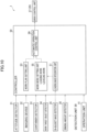
- the controller 50 includes a detection result acquisition unit 50a, a loading mass integration unit 51, a work plan setting unit 53, a work mode setting unit 55, a leveling operation end determination unit 56, an actual speed acquisition unit 57, and an automatic operation control unit 59.
- the detection result acquisition unit 50a acquires a detection result of the detection unit 30.
- the detection result acquisition unit 50a may acquire a detection result of the state of the work target object A in the container 13, and specifically, for example, may acquire a detection result of the work target object detector 34.
- the detection result acquisition unit 50a may acquire a detection result of the state of the container 13, and specifically, for example, may acquire a detection result of at least one of the container detector 33 and the sinking amount detector 36.
- the detection result acquisition unit 50a may acquire a detection result of the state of the work machine 20, and specifically, for example, may acquire a detection result of at least one of the attitude detector 31 and the load detector 37.
- the detection result acquisition unit 50a may acquire a detection result of the imaging device 32 or may acquire a detection result of the loading mass detector 35.
- the loading mass integration unit 51 calculates an integrated value of the mass of the work target object A loaded into the container 13 illustrated in FIG. 1 .
- the loading mass integration unit 51 calculates an integrated value from the start of the loading work to be described later (a state where the container 13 has no or approximately no work target object A) to the present.
- the loading mass integration unit 51 integrates the mass of the work target object A detected by the loading mass detector 35 at the time of loading the work target object A from the distal end attachment 25c to the container 13 every time.
- the work plan setting unit 53 sets a work plan of the work machine 20.
- the work plan is information regarding a work target of the work machine 20.
- the work plan may include information of a target range in which the distal end attachment 25c performs work.
- the information of the target range may include, for example, information of a target capturing range C to be described later illustrated in FIG. 2 .
- the work plan may include information of a target path of a specific portion of the attachment 25.
- the specific portion may be, for example, the arm distal end portion 25bt or the distal end attachment distal end portion 25ct.
- the target path of the specific portion may be, for example, the target path P of the leveling work illustrated in FIG. 5 .
- the work plan may include information of the slewing angle of the upper slewing body 23.
- the work plan may include information of a radius from a slewing center of the upper slewing body 23 with respect to the lower travelling body 21 to the specific portion (information in the machine forward/rearward direction X).
- the work plan may include information of the height (position in the upward/downward direction Z) of the specific portion.
- the information of the height of the specific portion may include, for example, information of the height from the lower portion of the upper slewing body 23 to the specific portion.
- At least a part of the work plan may be set by the work plan setting unit 53 on the basis of teaching, or may be set by the work plan setting unit 53 on the basis of a method other than teaching (for example, numerical value input by an operator).
- the work mode setting unit 55 sets a work mode.
- the work mode is a type of operation of work performed by the work machine 20.
- the work mode setting unit 55 selects and sets one work mode from a plurality of work modes.
- the work mode setting unit 55 changes the work mode.
- the work mode can be variously set.
- the work mode includes a leveling work mode.
- the work mode may include a mode of work different from the leveling work. Specifically, for example, the work mode may include a loading work mode to be described later, and may include a work mode for stirring or moving the work target object A within a certain range, and the like.
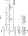
- the leveling operation end determination unit 56 determines whether or not a leveling operation end condition (see FIG. 7 ) is satisfied. The leveling operation end determination unit 56 determines whether or not to end (stop) the leveling operation during the leveling operation to be described later. Details of this determination will be described later.
- the actual speed acquisition unit 57 acquires a value regarding the actual speed of the attachment 25.
- the "value regarding the actual speed of the attachment 25” may be a value of the actual speed of the attachment 25 or may be a value that can be converted into the actual speed of the attachment 25.
- the "actual speed of the attachment 25” may be, for example, the actual speed of the distal end attachment 25c.
- the value regarding the actual speed of the attachment 25 is also simply referred to as "actual speed of the attachment 25".
- the actual speed acquisition unit 57 may acquire the actual speed of the attachment 25 from the detection result of the attitude detector 31.
- the actual speed acquisition unit 57 may acquire an angular speed of the attachment 25 (for example, an angular speed of the boom 25a with respect to the upper slewing body 23). In this case, the actual speed acquisition unit 57 may calculate the angular speed from the angle or the angular acceleration of the attachment 25 (the calculation is included in the acquisition). The actual speed acquisition unit 57 may acquire the actual speed of the attachment 25 on the basis of information of a change in inclination of the attachment 25 with respect to the horizontal direction (for example, inclination of the boom 25a). The actual speed acquisition unit 57 may acquire the actual speed of the attachment 25 on the basis of information of the stroke speed of the actuator 26 (cylinder).
- the actual speed acquisition unit 57 may acquire the actual speed of the attachment 25 on the basis of the information of the change in the image detected by the attitude detector 31 (the image captured by the imaging device 32). In this case, for example, the actual speed acquisition unit 57 may calculate the actual speed of the attachment 25 on the basis of a difference (change) of the image using the image for each control cycle.
- the work system 1 is configured to operate as follows.
- An outline of the operation of the work system 1 is as follows.
- the controller 50 (specifically, the automatic operation control unit 59) causes the work machine 20 to perform a leveling work by automatic operation.
- the leveling work is a work including a plurality of leveling operations.
- the work plan setting unit 53 sets a work plan for the leveling work.
- the work mode setting unit 55 sets (selects) a mode of the leveling work.
- the automatic operation control unit 59 operates the work machine 20 according to the work plan corresponding to the mode (leveling work mode) set by the work mode setting unit 55. As a result, the work machine 20 performs the leveling work by automatic operation according to the work plan.
- the controller 50 may cause the work machine 20 to perform the loading work by automatic operation.
- the controller 50 may cause the work machine 20 illustrated in FIG. 2 to perform the loading work by automatic operation (step S10 in FIG. 4 ).
- the loading work is a work of loading the work target object A into the container 13 by the distal end attachment 25c.
- a specific example of the loading work is as follows.
- the loading work includes a plurality of work phases (work contents).
- the plurality of work phases includes a capturing phase, a lifting slewing phase, a release phase, and a return slewing phase.
- the capturing phase is a phase in which the distal end attachment 25c captures the work target object A in the target capturing range C (for example, excavates earth and sand).
- Various setting values (such as thresholds) other than the number threshold may be manually set by the worker, may be automatically calculated by the controller 50, or may be values preset in the controller 50.
- the loading work end condition may include that the mass of the work target object A loaded into the container 13 in the loading work has reached a target value (integrated loading mass threshold) (step S13 in FIG. 4 ). More specifically, the loading work end condition may include that the value calculated by the loading mass integration unit 51 (see FIG. 3 ) has reached the integrated loading mass threshold (has become equal to or more than the integrated loading mass threshold).
- the controller 50 causes the work machine 20 to end the loading work (step S15 in FIG. 4 ). Specifically, for example, when ending the loading work, the automatic operation control unit 59 outputs a command to end the loading work to the drive control unit 27. As a result, the work machine 20 ends the loading work.
- the plurality of top portions (the first top portion A1, the second top portion A2, and the third top portion A3) is formed at positions shifted from each other in the container forward/rearward direction V and are not shifted from each other in the container width direction W, but the present invention is not limited to such an arrangement.
- the plurality of top portions may not be shifted from each other in the container forward/rearward direction V, and may be formed so as to be aligned in the container width direction W, and may be shifted from each other in the container width direction W.
- the controller 50 (specifically, the automatic operation control unit 59) causes the work machine 20 illustrated in FIG. 1 to start the leveling work, for example, after completion of the loading work.
- the leveling work is a work of leveling the work target object A loaded into the container 13 by using the distal end attachment 25c.
- the direction (pressing direction) in which the distal end attachment 25c presses the work target object A in the leveling operation may be the downward direction Z2. That is, the plurality of leveling operations may include a press-leveling operation in the downward direction Z2.
- the pressing direction may be a direction directly below the distal end attachment 25c (a direction coinciding with a vertically downward direction), or may be a direction inclined with respect to the direction directly below (obliquely downward direction).
- the pressing direction may be a horizontal direction (a direction orthogonal to the upward/downward direction Z). That is, the plurality of leveling operations may include a press-leveling operation in a horizontal direction (horizontal leveling operation).
- the mountain-shaped high portion for example, the first top portion A1 and its peripheral portion
- the mountain-shaped high portion of the work target object A is crushed.
- the mountain-shaped high portion of the work target object A flows to a low portion of the work target object A, for example, a portion outside the peripheral portion of the first top portion A1, and the high portion collapses.
- the high portion of the work target object A becomes lower, and the low portion of the work target object A becomes higher.
- the work target object A is leveled in a range wider than the leveling surface 25c2, and the wider range becomes flat or approximately flat.
- the distal end attachment 25c is set to an attitude (angle) suitable for pressing and leveling the work target object A.
- the controller 50 sets the attitude of the distal end attachment 25c so that the leveling surface 25c2 is parallel or approximately parallel to the horizontal direction as indicated by a two-dot chain line in FIG. 1 .
- the controller 50 (specifically, the automatic operation control unit 59) causes the work machine 20 to perform a leveling operation on the basis of the detection result acquired by the detection result acquisition unit 50a. Specifically, the controller 50 determines at least one of a leveling operation start position Ps and a leveling operation end position Pe on the basis of the detection result acquired by the detection result acquisition unit 50a. Then, the controller 50 causes the work machine 20 to perform the leveling operation on the basis of the determined position. In the present embodiment, the controller 50 determines both the leveling operation start position Ps and the leveling operation end position Pe.
- the leveling operation start position Ps is a start position of the leveling operation (one leveling operation). Specifically, in the leveling operation (one leveling operation) performed at a place corresponding to a certain position P1, the leveling operation start position Ps is the position of the distal end attachment 25c when the distal end attachment 25c starts the leveling operation. In the example illustrated in FIG. 5 , the leveling operation start position Ps is the position of the leveling surface 25c2 at the start of the leveling operation.
- the leveling operation end position Pe is an end position of the leveling operation (one leveling operation). For example, when the distal end attachment 25c performs the press-leveling operation of pressing the work target object A in the downward direction Z2, the leveling operation end position Pe is the position of the distal end attachment 25c when the distal end attachment 25c is arranged lowermost in the downward direction Z2 in the leveling operation (one leveling operation) performed immediately below the certain position P1. In the example illustrated in FIG. 5 , the leveling operation end position Pe is the position of the leveling surface 25c2 at the end of the leveling operation.
- the controller 50 causes the work machine 20 to perform a plurality of leveling operations in the leveling work.
- the leveling work includes a plurality of leveling operations.
- the controller 50 causes the distal end attachment 25c to perform a plurality of leveling operations while changing the position of the distal end attachment 25c.
- the controller 50 causes the distal end attachment 25c to perform the leveling operation at a location corresponding to each of the position P1, a position P2, and a position P3.
- the controller 50 causes the work machine 20 to perform a leveling operation (leveling work) so as to level the work target object A in the container 13 in order from a high portion. More specifically, on the basis of the detection result of the work target object detector 34, the controller 50 determines the leveling operation start position Ps of each time so as to level the work target object A in the container 13 in order from the high portion. Then, the controller 50 causes the work machine 20 to perform the leveling operation of each time so as to start the leveling operation from the determined leveling operation start position Ps.
- a leveling operation leveling work
- the controller 50 may cause the work machine 20 to perform the leveling work in descending order of heights of a plurality of vertex portions (the first top portion A1, the second top portion A2, and the third top portion A3) at a time point before the leveling work is performed (at the start of the leveling work). Specifically, for example, the controller 50 stores the positions of the plurality of vertex portions (the first top portion A1, the second top portion A2, and the third top portion A3) detected by the work target object detector 34 at the start of the leveling work. The controller 50 specifies the order (in the specific example illustrated in FIG. 5 , the order of the first top portion A1, the second top portion A2, and the third top portion A3) of the heights of the plurality of vertex portions.
- the controller 50 causes the distal end attachment 25c to perform the leveling operation at the position P1 corresponding to the highest first top portion A1 of the work target object A in the container 13 and in the vicinity thereof.
- the controller 50 causes the distal end attachment 25c to perform the leveling operation at and near the position P2 corresponding to the second highest vertex portion (second top portion A2) at the start of the leveling work.
- the controller 50 may cause the distal end attachment 25c to perform the leveling operation at the position P2 corresponding to the second top portion A2 and in the vicinity thereof.
- the controller 50 causes the distal end attachment 25c to perform the leveling operation at and near the position P3 corresponding to the third highest vertex portion (third top portion A3) at the start of the leveling work. At this time, even if a portion higher than the third top portion A3 exists in the work target object A in the container 13, the controller 50 may cause the distal end attachment 25c to perform the leveling operation at the position P3 corresponding to the third top portion A3 and in the vicinity thereof.
- the controller 50 may cause the work machine 20 to perform the leveling work so as to level the highest portion of the work target object A in the container 13 at a time point before each leveling operation (at the start of each leveling operation). Specifically, for example, similarly to the above Example 2A, the controller 50 causes the distal end attachment 25c to perform the leveling operation (first leveling operation) at and near the position P1 corresponding to the highest first top portion A1 of the work target object A in the container 13. Then, the shape of the work target object A in the container 13 changes. At this time, the work target object detector 34 detects the shape of the work target object A after the first leveling operation.
- the controller 50 causes the distal end attachment 25c to perform the leveling operation (second leveling operation) in the highest portion of the work target object A after the first leveling operation.
- the highest portion of the work target object A after the first leveling operation is not limited to the second top portion A2.
- the work target object detector 34 detects the shape of the work target object A after the second leveling operation.
- the controller 50 causes the distal end attachment 25c to perform the leveling operation in the highest portion of the work target object A after the second leveling operation.
- the highest portion of the work target object A after the second leveling operation is not limited to the second top portion A2 and is not limited to the third top portion A3.
- the controller 50 disposes the distal end attachment 25c as follows when causing the distal end attachment 25c to perform the press-leveling operation immediately below a position corresponding to a certain top portion. For example, when the leveling operation is performed immediately below the position P1 corresponding to the first top portion A1, the distal end attachment 25c is arranged so that the leveling surface 25c2 and the first top portion A1 face each other in the upward/downward direction Z. That is, as illustrated in FIG.
- the distal end attachment 25c when the work target object A is viewed from above, the distal end attachment 25c is arranged so that the first top portion A1 is included within the range of the position (position P1) of the leveling surface 25c2.
- the distal end attachment 25c may be arranged so that a central portion (central portion of the position P1) of the leveling surface 25c2 and the first top portion A1 coincide or approximately coincide with each other.
- the distal end attachment 25c moves in the downward direction Z2 in a state where the leveling surface 25c2 and the first top portion A1 face each other in the upward/downward direction Z.
- the distal end attachment 25c levels the first top portion A1 and the work target object A therearound.
- the controller 50 causes the distal end attachment 25c to perform the horizontal leveling operation so as to level the work target object A in the container 13 in order from a high portion.
- the controller 50 may cause the distal end attachment 25c to perform horizontal leveling at the first top portion A1 and the peripheral portion of the first top portion A1.
- the peripheral portion of the first top portion A1 may be, for example, a position that does not reach the second top portion A2 and the third top portion A3.
- the controller 50 may cause the distal end attachment 25c to perform the horizontal leveling operation in the region from the first top portion A1 to the second top portion A2.
- the distal end attachment 25c performs the horizontal pull-leveling operation in the region from the first top portion A1 to the third top portion A3 does not correspond to leveling the work target object A in the container 13 in order from a high portion.
- the controller 50 preferably controls the position of the distal end attachment 25c so that the contact between the container 13 (for example, the container wall surface 13b) and the distal end attachment 25c can be suppressed when the leveling work is performed, that is, when the leveling operation of each time is performed.
- the controller 50 may control the position of the distal end attachment 25c so that a distance (horizontal distance) in the horizontal direction between the distal end attachment 25c and the container wall surface 13b when the leveling work is performed is equal to or more than a predetermined threshold (distance threshold).
- the distance threshold can be set in various ways. The distance threshold may be manually set by the worker, or may be automatically set by the controller 50 (specifically, the work plan setting unit 53).
- the distance threshold may be automatically set by the controller 50 on the basis of the information of the container 13 detected by the container detector 33 and information of dimensions of the distal end attachment 25c.
- the distance threshold may be an initial value, a fixed value, or the like preset in the controller 50.
- a range in which the distal end attachment 25c levels the work target object A in one leveling operation at a place corresponding to a certain position is referred to as a leveling operation range Q.
- the leveling operation range Q in a case where the distal end attachment 25c performs the press-leveling operation immediately below (or approximately immediately below) the distal end attachment 25c is a region immediately below (or approximately immediately below) the distal end attachment 25c (specifically, the leveling surface 25c2).
- the leveling operation range Q is a range of the work target object A that is lower in the downward direction Z2 than the distal end attachment 25c that performs the leveling operation and faces the distal end attachment 25c in the upward/downward direction Z.
- the size of the leveling operation range Q is the same as or approximately the same as the size of the distal end attachment 25c.
- the leveling operation range Q in a case where the distal end attachment 25c performs the press-leveling in the horizontal direction may be a range of the work target object A in which the distal end attachment 25c and the work target object A are predicted to come into contact in the leveling operation, and may be a range when the range is viewed from above.
- the size of the leveling operation range Q may be wider than the size of the distal end attachment 25c (not illustrated).
- the leveling operation range Q can also be referred to as a range of the leveling surface 25c2 when the leveling surface 25c2 arranged at the target position such as the position P1 illustrated in FIG. 2 when leveling the work target object A is viewed from above.
- the distal end attachment 25c When the distal end attachment 25c performs the leveling operation of leveling the work target object A, a part of the work target object A is pushed out to the periphery of the leveling operation range Q and protrudes from the range. Further, an upper surface of the work target object A around the leveling operation range Q may become higher than an upper surface of the work target object A in the leveling operation range Q. In this case, the leveling operation is preferably performed so as to level the work target object A pushed out around the leveling operation range Q.
- the controller 50 causes the work machine 20 to perform the leveling operation while sequentially updating the leveling operation range Q to various positions in the container 13 so as to level the work target object A in the container 13 in order from a high portion.
- the controller 50 preferably changes the leveling operation range Q so that parts of the adjacent leveling operation ranges Q overlap each other.
- a lap portion Ql in which parts of the adjacent leveling operation ranges Q overlap each other is formed.
- the controller 50 preferably sets the target path P of the leveling work so that the lap portion Ql is provided.
- the target path P includes a plurality of target positions, and the plurality of target positions include, for example, the target position P1, the target position P2, and the target position P3 illustrated in FIGS.
- the controller 50 controls the operation of the work machine 20 so that the specific portion (for example, the arm distal end portion 25bt) of the attachment 25 sequentially moves through the plurality of target positions included in the target path P, and controls the operation of the work machine 20 so that the distal end attachment 25c performs the leveling operation at the place corresponding to each of the plurality of target positions.
- the leveling operation start position Ps to be described later may be set at the same position as each target position, or may be set immediately below each target position.
- the direction in which the two adjacent leveling operation ranges Q are arranged may be the container forward/rearward direction V, the container width direction W, the machine slewing direction Sw, or the machine forward/rearward direction X.
- the direction in which the two adjacent leveling operation ranges Q are arranged is the container forward/rearward direction V or the container width direction W. More specifically, in the specific example of FIG. 6 , a leveling operation range Qa and a leveling operation range Qb located adjacent to the leveling operation range Qa are arranged in the container width direction W, and an end portion of the leveling operation range Qa and an end portion of the leveling operation range Qb overlap each other.
- leveling operation range Qa and a leveling operation range Qc located adjacent to the leveling operation range Qa are arranged in the container forward/rearward direction V, and an end portion of the leveling operation range Qa and an end portion of the leveling operation range Qc overlap each other.
- the width of the lap portion Ql (the amount of overlap) may be set by manual operation of the worker (for example, input of information to the operation unit 41 by the worker), or may be automatically set by the controller 50 (the work plan setting unit 53).
- the width of the lap portion Ql may be set on the basis of the shape of the work target object A around the leveling operation range Q detected by the work target object detector 34, that is, the shape of the work target object A pushed out around the leveling operation range Q.
- the controller 50 may set a height (position in upward/downward direction Z) of the leveling operation start position Ps in the leveling operation (one leveling operation) in a place corresponding to the certain position P1 illustrated in FIG. 5 as follows.
- the leveling operation start position Ps may be set higher in the upward direction Z1 than the work target object A immediately below the position P1.
- the leveling operation start position Ps may be calculated on the basis of the height of the work target object A detected by the work target object detector 34.
- the leveling operation start position Ps may be set to a position corresponding to the position P1 and a height obtained by adding a preset value (a value equal to or more than zero) to the height of the top portion of the work target object A immediately below the position P1.
- the leveling operation start position Ps may be set on the basis of the leveling operation end position Pe.
- the leveling operation start position Ps may be a position in the upward direction Z1 from the leveling operation end position Pe by a predetermined value.
- the predetermined value may be set by manual operation of the worker (for example, input to the operation unit 41 by the worker), or may be automatically set by the controller 50.
- the controller 50 may set the leveling operation end position Pe in the leveling operation (one leveling operation) at the certain position P1 as follows, for example.
- the leveling operation end position Pe may be determined while the leveling operation is being performed at the place corresponding to the position P1 ([Example 4] below).
- the leveling operation end position Pe may be a position determined without performing the leveling operation ([Example 5] below).
- each step (S21 to S51) illustrated in FIG. 7 will be described with reference to FIG. 7 .
- the leveling operation end position Pe may be determined while the leveling operation is being performed at the place corresponding to the position P1 (after step S21). In this case, the leveling operation end determination unit 56 determines whether or not a leveling operation end condition (see steps S31, S41 to S44) is satisfied.
- the leveling operation end condition is a condition that the controller 50 (specifically, the automatic operation control unit 59) causes the distal end attachment 25c to end (stop) the leveling operation.
- the leveling operation end condition is set in the controller 50 in advance (before the leveling operation).
- the controller 50 may set the position of the distal end attachment 25c when the leveling operation end condition is satisfied as the leveling operation end position Pe. Then, after finishing the current leveling operation (after step S51), the controller 50 causes the distal end attachment 25c to perform the next leveling operation.
- the leveling operation end condition may include only one condition, or may include a plurality of conditions as illustrated in FIG. 7 .
- the leveling operation end determination unit 56 may determine that the leveling operation end condition is satisfied when at least one of the plurality of conditions is satisfied (see steps S31, S41 to S44). In addition, the leveling operation end determination unit 56 may determine that the leveling operation end condition is satisfied when two or more or all of the plurality of conditions are satisfied.
- the leveling operation end condition may include a condition regarding the container 13 (cargo bed of the vehicle 10) as described in [Example 4A] below, or may include a condition regarding the work machine 20 as described in [Example 4B] below.
- the leveling operation end condition may include a condition regarding the sinking amount of the cargo bed of the vehicle 10 as the container 13. Specifically, the leveling operation end condition may include that a value regarding the sinking amount of the cargo bed of the vehicle 10 detected by the sinking amount detector 36 exceeds a predetermined threshold (sinking amount threshold) (step S31).
- This sinking amount threshold is preset in the controller 50 (specifically, the leveling operation end determination unit 56). The threshold is previously set in the controller 50 similarly to other thresholds described later.
- the "value regarding the sinking amount” may be a decrease amount (sinking amount) of the height of the container 13 (cargo bed) with respect to the ground, may be the inclination of the container 13, may be a sinking speed of the container 13, or may be a sinking acceleration of the container 13.
- the value regarding the sinking amount is described as "sinking amount”.
- the reason why the leveling operation end condition includes the condition regarding the sinking amount in other words, the reason why the leveling operation end position Pe illustrated in FIG. 5 is set on the basis of the sinking amount of the container 13 is as follows. As illustrated in FIG. 1 , in the case where the container 13 is a cargo bed of the vehicle 10, the container 13 is pushed by the distal end attachment 25c via the work target object A and moves in the downward direction Z2 so as to approach the ground. In other words, when the bucket 25c pushes the work target object A, the container 13 sinks so as to approach the ground.
- the leveling operation end condition preferably includes a condition regarding the sinking amount as described above.
- the sinking amount threshold is preferably set to a value that can suppress the occurrence of these problems.
- the leveling operation end position Pe illustrated in FIG. 5 is preferably set (determined).
- the leveling operation end condition may include a condition regarding the magnitude of the reaction force received by the distal end attachment 25c from the work target object A when the distal end attachment 25c (work machine 20) performs the leveling operation.
- the "condition regarding the magnitude of the reaction force" may be, for example, a condition defined by the magnitude of the reaction force or a condition defined by a value correlated with the reaction force.
- the condition regarding the magnitude of the reaction force included in the leveling operation end condition may include a condition regarding the load acting on the distal end attachment 25c as described in [Example 4Ba] below, or may include a condition regarding the actual speed of the attachment 25 as described in [Example 4Bb] below.
- the leveling operation end condition may include a condition regarding a value regarding a load acting on the distal end attachment 25c.
- the "value regarding a load” is simply referred to as the "value of the load”.
- the leveling operation end condition may include a condition regarding the magnitude of the value of the load detected by the load detector 37.
- the leveling operation end condition may include that the value of the load detected by the load detector 37 exceeds a predetermined threshold (load threshold) (steps S41, S42, and S43).
- the load detector 37 may detect the value of the load acting on the attachment 25 illustrated in FIG. 1 , may detect the value of the load acting on the actuator 26, or may detect the vehicle body angle of the work machine body 20a.
- the leveling operation end condition may include that the value of the load (for example, stress) acting on the attachment 25 exceeds a predetermined threshold (step S41).
- the attachment 25 is denoted as "ATT" in FIG. 7 .
- the leveling operation end condition may include that the value of the load acting on the actuator 26 (cylinder) exceeds a predetermined threshold.
- the leveling operation end condition may include that the value of the load acting on the distal end attachment 25c exceeds a predetermined threshold (step S42).
- the leveling operation end condition may include that the vehicle body angle of the work machine body 20a exceeds a predetermined threshold (step S43).
- the leveling operation end condition may include a condition regarding the actual speed of the attachment 25 (specifically, for example, a condition regarding the actual speed of the distal end attachment 25c).
- the leveling operation end condition may include a condition regarding a value regarding the actual speed of the attachment 25 acquired by the actual speed acquisition unit 57.
- the "value regarding the actual speed” is simply referred to as an "actual speed”.
- the leveling operation end condition may include that the actual speed of the attachment 25 is less than a predetermined threshold (actual speed threshold) (step S44). Specifically, for example, it is assumed that the distal end attachment 25c receives a reaction force of a certain magnitude when the distal end attachment 25c performs the leveling operation, and the actual speed of the distal end attachment 25c is equal to or more than the actual speed threshold. Thereafter, when the reaction force received by the distal end attachment 25c increases, the actual speed of the distal end attachment 25c becomes less than the actual speed threshold. At this time, the controller 50 ends (stops) the leveling operation.
- a predetermined threshold actual speed threshold
- the leveling operation end condition may include a condition regarding a deviation amount of the actual speed of the attachment 25 from a target speed.
- the leveling operation end condition may include that the deviation amount exceeds a predetermined threshold (deviation amount threshold).
- the target speed of the attachment 25 is set in the work plan setting unit 53. Specifically, for example, it is assumed that the distal end attachment 25c receives a reaction force of a certain magnitude when the distal end attachment 25c performs the leveling operation, and the deviation amount is equal to or less than the deviation amount threshold. Thereafter, when the reaction force received by the distal end attachment 25c increases, the actual speed decreases with respect to the target speed of the distal end attachment 25c, and the deviation amount exceeds the deviation amount threshold. At this time, the controller 50 ends (stops) the leveling operation.
- the leveling operation end position Pe illustrated in FIG. 5 may be a position determined even if the leveling operation is not performed at the place corresponding to the position P1, that is, a position that can be determined before the leveling operation is performed.
- the leveling operation end position Pe may be set on the basis of information (for example, the shape of the work target object A) of the work target object A detected by the work target object detector 34.
- the leveling operation end position Pe corresponding to the position P1 may be set at a position that is lower in the downward direction Z2 than a top portion that is the next highest to the first top portion A1 corresponding to the position P1, that is, than the second top portion A2 corresponding to the position P2.
- the controller 50 specifies the highest first top portion A1 of the work target object A in the container 13 and the second top portion A2 that is the next highest to the first top portion A1 of the work target object A in the container 13.
- the controller 50 causes the work machine 20 to perform the leveling work on the first top portion A1 so that the work target object A on the first top portion A1 becomes lower than the second top portion A2.
- the height of the highest portion of the work target object A in the container 13 is reliably lowered.
- the leveling operation end position Pe corresponding to the position P1 may be set on the basis of the height of the first top portion A1 corresponding to the position P1.
- the leveling operation end position Pe may be a position lower than the height of the first top portion A1 by a predetermined press-down amount.
- the predetermined press-down amount may be set by manual operation of the worker (for example, input of information to the operation unit 41 by the worker), or may be automatically set by the controller 50.
- the leveling operation end position Pe may be set on the basis of information (for example, the position of the container 13, the shape of the container 13, and the like) of the container 13 detected by the container detector 33.
- the leveling operation end position Pe may be set on the basis of the height of the container 13, for example, may be set on the basis of the height of the container wall surface 13b (for example, the height of the tail gate plate surface 13b1 or the height of the side gate panel surface 13b2).
- the leveling operation end position Pe may be set on the basis of the height of the container floor surface 13a.
- the leveling operation end position Pe may be set by manual operation of the worker (for example, input of information to the operation unit 41 by the worker).
- the controller 50 moves the distal end attachment 25c from the leveling operation start position Ps to the leveling operation end position Pe at the location corresponding to the target position P1
- the controller ends the leveling operation at the place corresponding to the position P1 (step S51).
- the controller 50 may move (return) the distal end attachment 25c to, for example, the same position as the leveling operation start position Ps corresponding to the position P1.
- the controller 50 may move the distal end attachment 25c to the leveling operation start position Ps corresponding to the next target position P2.
- the controller 50 may move the distal end attachment 25c to a position different from the leveling operation start position Ps corresponding to the target position P1, for example, the leveling operation start position Ps corresponding to the next target position P2.
- a configuration of the work system 1 according to the first embodiment illustrated in FIGS. 1 to 7 and an effect obtained by the configuration are as follows.
- the work system 1 is a system for automatically operating the work machine 20 including the attachment 25 (work device 25).
- the work system 1 includes the controller 50 that controls an operation of the work machine 20 so that a leveling work is performed, the leveling work including a leveling operation in which the work target object A that has been loaded into the container 13 by a loading work is leveled using the work device 25.
- the controller 50 acquires information regarding at least one of the work target object A in the container 13, the container 13, and the work machine 20, and determines at least one of a start position of the leveling operation and an end position of the leveling operation by using the information.
- the information acquired by the detection result acquisition unit 50a of the controller 50 includes information regarding at least one of a state of the work target object A in the container 13, a state of the container 13, and a state of the work machine 20, and the controller 50 controls the operation of the work machine 20 so that the leveling operation is performed using at least one of the start position and the end position that has been determined. Therefore, the work system 1 can cause the work machine 20 to efficiently perform the leveling work by automatic operation.
- the outline of the work system 1 according to the first embodiment is as described above.
- the work device 25 includes the distal end attachment 25c.
- the work system 1 includes the detection result acquisition unit 50a and the automatic operation control unit 59.
- the detection result acquisition unit 50a acquires a detection result of a state of at least one of the work target object A in the container 13, the container 13, and the work machine 20.
- the automatic operation control unit 59 determines at least one of a start position (leveling operation start position Ps) and an end position (leveling operation end position Pe) of the leveling operation illustrated in FIG. 5 on the basis of the detection result acquired by the detection result acquisition unit 50a.
- the "leveling operation” is an operation of leveling the work target object A in the container 13 with the distal end attachment 25c.
- the automatic operation control unit 59 causes the work machine 20 to perform the leveling operation by automatic operation on the basis of the determined position.
- At least one of the start position (leveling operation start position Ps) and the end position (leveling operation end position Pe) of the leveling operation is determined on the basis of the detection result acquired by the detection result acquisition unit 50a.
- this detection result is a detection result of the state of at least one of the work target object A in the container 13, the container 13, and the work machine 20.
- the automatic operation control unit 59 can automatically set at least one of the start position (leveling operation start position Ps) and the end position (leveling operation end position Pe) of the leveling operation to an appropriate position according to the detection result. Therefore, the work system 1 can cause the work machine 20 to efficiently perform the leveling work by automatic operation.
- the detection result acquisition unit 50a acquires a detection result of the state of the work target object A.
- the automatic operation control unit 59 of the controller 50 may determine a high portion of the work target object A in the container 13 as the start position by using the information regarding the state of the work target object A, and control an operation of the work machine 20 so that the leveling operation is started from the high portion. For example, on the basis of the detection result acquired by the detection result acquisition unit 50a, the automatic operation control unit 59 causes the work machine 20 to perform a leveling operation so as to level the work target object A in the container 13 in order from a high portion.
- the controller 50 may determine whether or not to end the leveling operation by using the information.
- the information regarding the state of the container 13 may include information regarding a decrease amount (sinking amount) of the height of the cargo bed with respect to the ground, and the controller 50 may determine the end position by using the information regarding the decrease amount (sinking amount). That is, the controller 50 may determine whether or not to end the leveling operation by using the information regarding the decrease amount (the sinking amount).
- the detection result acquisition unit 50a acquires a detection result regarding a decrease amount (sinking amount) of the height of the cargo bed, which is the container 13 illustrated in FIG. 5 , with respect to the ground.
- the condition (leveling operation end condition) under which the automatic operation control unit 59 causes the distal end attachment 25c to end the leveling operation includes a condition regarding the sinking amount of the container 13 (cargo bed) acquired by the detection result acquisition unit 50a (see step S31 in FIG. 7 ).
- the leveling operation is a first leveling operation of leveling the work target object A by using the attachment 25 (work device 25) in a first leveling range
- the leveling work may further include a second leveling operation of leveling the work target object A by using the attachment 25 in a second leveling range
- the controller 50 may control the operation of the work machine 20 so that a part of the second leveling range overlaps the first leveling range when viewed from above.
- the automatic operation control unit 59 While changing the leveling operation range Q, the automatic operation control unit 59 causes the work machine 20 to perform the leveling operation a plurality of times so that parts of the adjacent leveling operation ranges Q overlap with each other (so that the lap portion Ql is provided).
- the work system 1 can cause the work machine 20 to perform the leveling operation so as to level the work target object A more flatly as compared with the case where [Configuration 5] above is not provided.
- the controller 50 may specify the first top portion A1 that is a highest portion of the work target object A in the container 13 and the second top portion A2 that is the next highest portion after the first top portion A1 of the work target object A in the container 13 by using information regarding the state of the work target object A in the container 13, and the leveling operation may be an operation of leveling a portion including the first top portion A1 so that the portion including the first top portion A1 becomes lower than the second top portion A2.
- the automatic operation control unit 59 specifies first top portion A1 and second top portion A2 illustrated in FIG. 5 on the basis of the detection result acquired by the detection result acquisition unit 50a.
- the first top portion A1 is the highest portion of the work target object A in the container 13.
- the second top portion A2 is the next highest portion after the first top portion A1 of the work target object A in the container 13.
- the automatic operation control unit 59 causes the work machine 20 to perform the leveling operation on the first top portion A1 so that the work target object A on the first top portion A1 becomes lower than the second top portion A2.
- the portion of the highest first top portion A1 of the work target object A in the container 13 becomes lower than the second top portion A2.
- the height of the highest portion of the work target object A in the container 13 can be reliably lowered.
- the detection result acquisition unit 50a acquires a detection result of a state of at least one of the cargo bed which is the container 13 and the work machine 20.
- a condition (leveling operation end condition) regarding the detection result acquired by the detection result acquisition unit 50a is satisfied while the work machine 20 is performing the leveling operation
- the automatic operation control unit 59 causes the work machine 20 to end the leveling operation.
- the leveling operation can be ended in an appropriate state according to the detection result of the state of at least one of the cargo bed which is the container 13 and the work machine 20.
- the automatic operation control unit 59 can automatically set the end position of the leveling operation (leveling operation end position Pe) at an appropriate position according to the detection result. Therefore, the work system 1 can cause the work machine 20 to efficiently perform the leveling work by automatic operation.
- the work system 1 includes the work machine 20.
- the detection result acquisition unit 50a and the automatic operation control unit 59 are mounted on the work machine 20. That is, in the first embodiment, the controller 50 may include an acquisition unit (detection result acquisition unit 50a) that acquires the information, and an automatic operation control unit 59 that determines at least one of the start position and the end position by using the information, and controls the operation of the work machine 20 so that the leveling operation is performed using at least one of the start position and the end position that has been determined, and the detection result acquisition unit 50a and the automatic operation control unit 59 may be mounted on the work machine 20. The same applies to the work system 1 according to the second embodiment described later.
- the above first embodiment may be variously modified.
- the number of components of the above embodiment may be changed, and some of the components do not have to be provided.
- the connection of the components illustrated in FIG. 3 or the like may be changed.
- a plurality of members and parts different from each other may be described as one member and part.
- what has been described as one member and part may be divided into a plurality of different members and parts.
- the components (the work plan setting unit 53, the automatic operation control unit 59, and the like) of the controller 50 may be separately provided.
- various parameters may be preset in the controller 50, or may be directly set by manual operation of the worker (for example, operation of the operation unit 41, teaching, or the like).
- Various parameters may be calculated by the controller 50 on the basis of information set by manual operation of the worker, or may be calculated by the controller 50 on the basis of information detected by the detection unit 30.
- the various parameters may not be changed, may be changed by manual operation, or may be automatically changed by the controller 50 according to some condition.
- some of the steps in the flowcharts illustrated in FIGS. 4 and 7 may not be performed.
- the components each may have only some of features (function, arrangement, shape, manufacturing method, operation, and the like).
- the problem to be solved by the work system according to the second embodiment is that a work machine efficiently switches between a work of loading a work target object into a container by the work machine and a work of leveling the work target object that has been loaded into the container by the work machine.
- the work system includes a work machine and a controller, the work machine including a bucket, the controller causing the work machine to automatically operate.
- the controller causes the work machine to perform a loading work and a leveling work.
- the loading work is a work of loading a work target object into a container by the bucket.
- the leveling work is a work of leveling the work target object that has been loaded into the container with the bucket after the loading work is finished.
- the controller stores a position where the bucket is arranged at the end of the loading work as a loading end position.
- the controller causes the work machine to start the leveling work in a loading end position side region within a range of the container when viewed from above.
- the work system according to the second embodiment can efficiently switch work when the work of the work machine by automatic operation is changed from the loading work to the leveling work.
- a work system 1 according to the second embodiment will be described with reference to FIGS. 8 to 13 .
- the work system 1 is a system in which a work machine 20 performs work on a container 13.
- the work system 1 includes a vehicle 10, a work machine 20, a detection unit 30 illustrated in FIG. 10 , an operation unit 41, and a controller 50.
- the vehicle 10 is a machine (transport vehicle) that transports a transported object (work target object A) stored in the container 13.
- the vehicle 10 is, for example, a dump truck or the like.
- the vehicle 10 includes a vehicle body 11 and a container 13.
- the configurations of the vehicle body 11 and the container 13 illustrated in FIG. 8 are similar to the configurations of the vehicle body 11 and the container 13 in the first embodiment described with reference to FIG. 1 and the like, and thus detailed description thereof will be omitted.
- the work machine 20 is a machine that performs work.
- the work machine 20 is a machine that performs a loading work and a leveling work.
- the work machine 20 is, for example, a construction machine that performs construction work, and is, for example, an excavator.
- the work machine 20 is configured to be operable by automatic operation. That is, the work machine 20 is automated so as to operate on the basis of a command input from the controller 50.
- the work machine 20 may be operable on the basis of an operation by a worker (operator) in the cab 23a, or may be configured to operate on the basis of a remote operation by an operator at a remote location away from the work machine 20.
- the work machine 20 includes a lower travelling body 21, an upper slewing body 23, an attachment 25, and a drive control unit 27.
- the configurations of the lower travelling body 21, the upper slewing body 23, the attachment 25, and the drive control unit 27 illustrated in FIGS. 8 to 10 are similar to the configurations of the lower travelling body 21, the upper slewing body 23, the attachment 25, and the drive control unit 27 in the first embodiment described with reference to FIGS. 1 to 3 and the like, and thus detailed description thereof will be omitted.
- the distal end attachment 25c is a bucket 25c.
- the leveling surface 25c2 in the first embodiment is referred to as a bucket distal end back surface 25c2 in the second embodiment
- the distal end attachment distal end portion 25ct in the first embodiment is referred to as a bucket distal end portion 25ct in the second embodiment.
- the work target object A in the second embodiment is an object to be worked by the work machine 20, similarly to the work target object A in the first embodiment.
- the work target object A is captured by the bucket 25c in a capturing phase, is released from the bucket 25c in a release phase, and is loaded into the container 13.
- the work target object A is leveled by the bucket 25c.
- the work target object A is earthy, granular, chip-like, powdery, massive, or the like.
- the work target object A may be soil, stone, wood, metal, or waste.
- the drive control unit 27 controls a plurality of actuators for driving the work machine 20.
- the plurality of actuators in the second embodiment are similar to the plurality of actuators 26 in the first embodiment.
- the drive control unit 27 controls a slewing motor that slews the upper slewing body 23 with respect to the lower travelling body 21.
- the drive control unit 27 controls a boom cylinder that raises and lowers the boom 25a with respect to the upper slewing body 23.
- the drive control unit 27 controls an arm cylinder that rotates the arm 25b with respect to the boom 25a.
- the drive control unit 27 controls a bucket cylinder (distal end attachment cylinder) that rotates the bucket 25c with respect to the arm 25b.
- the detection unit 30 detects various states in the work system 1.
- the detection unit 30 illustrated in FIG. 10 outputs a detection value to the controller 50.
- the detection unit 30 includes an attitude detector 31, an imaging device 32, a container detector 33, a work target object detector 34, an in-bucket mass detector 35 (loading mass detector 35), and a sinking amount detector 36.
- the configurations of the attitude detector 31, the imaging device 32, the container detector 33, the work target object detector 34, the in-bucket mass detector 35 (loading mass detector 35), and the sinking amount detector 36 in the second embodiment are similar to the configurations of the attitude detector 31, the imaging device 32, the container detector 33, the work target object detector 34, the loading mass detector 35, and the sinking amount detector 36 in the first embodiment, and thus detailed descriptions thereof will be omitted.
- the attitude detector 31 may include a boom attitude sensor that detects information (angle, angular speed, angular acceleration, or the like) of the rotation of the boom 25a with respect to the upper slewing body 23.
- the attitude detector 31 may include an arm attitude sensor that detects information of the rotation of the arm 25b with respect to the boom 25a.
- the attitude detector 31 may include a bucket attitude sensor (distal end attachment attitude sensor) that detects information of the rotation of the bucket 25c with respect to the arm 25b.
- the operation unit 41 is used by a worker to input information.
- the configuration of the operation unit 41 illustrated in FIG. 10 is similar to the configuration of the operation unit 41 in the first embodiment described with reference to FIG. 3 , and thus the detailed description thereof will be omitted.
- the controller 50 in the second embodiment is similar to the controller 50 in the first embodiment. That is, the controller 50 includes a computer that inputs and outputs signals, performs arithmetic (processing), stores information, and the like. For example, the function of the controller 50 is implemented by causing an arithmetic unit to execute a program stored in a storage unit of the controller 50. For example, the controller 50 receives a detection result from the detection unit 30. For example, the controller 50 performs control to cause the work machine 20 to automatically operate.
- the controller 50 is an automatic operation controller. For example, the controller 50 outputs a command for operating the work machine 20.
- the controller 50 includes a loading mass integration unit 51, a work plan setting unit 53, a work mode setting unit 55, and an automatic operation control unit 59.
- the controller 50 in the second embodiment does not have to include the detection result acquisition unit 50a, the leveling operation end determination unit 56, and the actual speed acquisition unit 57 of the controller 50 in the first embodiment.
- the controller 50 in the second embodiment may have functions similar to those of the detection result acquisition unit 50a, the leveling operation end determination unit 56, and the actual speed acquisition unit 57 of the controller 50 in the first embodiment.
- the functions of the loading mass integration unit 51, the work plan setting unit 53, the work mode setting unit 55, and the automatic operation control unit 59 in the second embodiment illustrated in FIG. 10 are similar to the functions of the loading mass integration unit 51, the work plan setting unit 53, the work mode setting unit 55, and the automatic operation control unit 59 in the first embodiment described with reference to FIG. 3 , and thus detailed description thereof will be omitted.
- the work system 1 is configured to operate as follows.
- An outline of the operation of the work system 1 is as follows.
- the controller 50 causes the work machine 20 to perform a loading work and a leveling work by automatic operation.
- the work plan setting unit 53 sets a work plan for the loading work and the leveling work.
- the work mode setting unit 55 sets (selects) a mode of the loading work or a mode of the leveling work.
- the automatic operation control unit 59 operates the work machine 20 according to the work plan corresponding to the mode set in the work mode setting unit 55. As a result, the work machine 20 operates by automatic operation according to the work plan.
- the work machine 20 may be arranged at various relative positions with respect to the container 13.
- the work machine 20 may be arranged so as to face the container 13 in the container forward/rearward direction V.
- the work machine 20 is arranged in the container rearward direction V2 with respect to the container 13.
- the work machine 20 may be arranged so as to face the container 13 in the container width direction W.
- the work machine 20 is arranged in the container leftward direction W1 with respect to the container 13.
- the work machine 20 may be arranged in the container rightward direction W2 with respect to the container 13.
- the controller 50 causes the work machine 20 illustrated in FIG. 9 to perform the loading work by automatic operation (step S10 in FIG. 11 ).
- the loading work is a work of loading the work target object A into the container 13 by the bucket 25c.
- a specific example of the loading work is as follows.
- the loading work includes a plurality of work phases (work contents).
- the plurality of work phases includes a capturing phase, a lifting slewing phase, a release phase, and a return slewing phase.
- the capturing phase is a phase in which the bucket 25c captures the work target object A in the target capturing range C (for example, excavates earth and sand).
- the target capturing range C may be set at a place where the work target object A is collected (for example, a soil sand pile, a soil pit, and the like), or may be set on the ground as an excavation object.
- the lifting slewing phase is a phase in which the bucket 25c moves from the target capturing range C toward a position immediately above the container 13 in a state where the bucket 25c captures the work target object A.
- the bucket 25c moves in the machine slewing direction Sw and the upward/downward direction Z (mainly the upward direction Z1).
- the release phase is a phase in which the bucket 25c releases (for example, discharges) the work target object A immediately above the container 13 (loading position E).
- the return slewing phase is a phase in which the bucket 25c moves from the position immediately above the container 13 toward the target capturing range C.
- the bucket 25c moves in the machine slewing direction Sw and the upward/downward direction Z (mainly the downward direction Z2).
- a series of work phases including the capturing phase, the lifting slewing phase, the release phase, and the return slewing phase is repeatedly performed.
- a position (loading position E) at which the work target object A is loaded from the bucket 25c into the container 13 can be variously set.
- the loading position E may be different in each of the plurality of release phases, or may be the same position until a certain condition is satisfied.
- the loading position E may be changed in order in a predetermined direction. That is, the loading positions E of the plurality of release phases may be changed so as to be shifted in a predetermined direction as the number of times increases.
- the loading position E may be changed in order in the container forward/rearward direction V (longitudinal direction of the container 13).
- the loading position E may be changed in order in the container forward direction V1 or in order in the container rearward direction V2.
- the loading position E may be changed in order in the container width direction W.
- the loading position E may be changed in order in the container rightward direction W2 or may be changed in order in the container leftward direction W1.
- the loading position E may be changed in order in the machine slewing direction Sw.
- the loading position E may be changed in order in the machine forward/rearward direction X.
- the loading position E may be changed in order from a position close to one end of the container 13 toward a position close to the other end (an end opposite to the one end).
- the loading position E does not have to be changed in order in a predetermined direction, and may be randomly changed.
- the method of setting the loading position E is not limited to the above specific example.
- a loading work end condition is set in advance (before the determination of the end of the loading work is performed).
- the loading work end condition is a condition for ending the loading work on the work machine 20.
- the loading work end condition is also a condition (leveling work start condition) for causing the work machine 20 to start the leveling work.
- the loading work end condition can be set variously.
- the loading work end condition may include only one condition, or may include a plurality of conditions as illustrated in FIG. 11 .
- the controller 50 may end the loading work when at least one of the plurality of conditions included in the loading work end condition is satisfied, or may end the loading work when two or more (for example, all) of the plurality of conditions included in the loading work end condition are satisfied.
- a specific example of the loading work end condition is as follows.
- the loading work end condition may include that a command to end the loading work is output.
- the loading work end condition may include that a command to start the leveling work is output.
- the loading work end condition may include that a command to change the work mode from the loading work mode to the leveling work mode is output.
- the loading work end condition may include that the above command is output from the operation unit 41 (see FIG. 3 ) (step S11 in FIG. 11 ).
- the loading work end condition may include that a command to end the loading work (a command not depending on an operation by the worker) is output from an element other than the operation unit 41.
- the loading work end condition may include that the number of times of loading from the bucket 25c to the container 13 illustrated in FIG. 9 (the number of times of performing the series of phases) has reached a predetermined number of times (number threshold) (step S12 in FIG. 11 ).
- the number threshold may be set by manual operation of the worker (input of information to the operation unit 41 by the worker).
- a value of the number of times that is the number threshold may be set by the operation unit 41.
- information for setting the number threshold may be set by the operation unit 41, and the controller 50 may calculate the number threshold on the basis of the information set by the operation unit 41.
- the controller 50 may calculate the number threshold on the basis of manually set information (dimensions and the like) of the container 13.
- the number threshold may be automatically set by the controller 50.
- the controller 50 may calculate the number threshold on the basis of the information of the container 13 detected by the container detector 33.
- the number threshold may be an initial value, a fixed value, or the like preset in the controller 50.
- Various setting values (such as a threshold and an adjustment value) other than the number threshold may be manually set by the worker, may be automatically calculated by the controller 50, or may be values preset in the controller 50.
- the loading work end condition may include that the mass of the work target object A loaded into the container 13 in the loading work has reached a target value (integrated loading mass threshold) (step S13 in FIG. 11 ). More specifically, the loading work end condition may include that the value calculated by the loading mass integration unit 51 (see FIG. 3 ) has reached the integrated loading mass threshold (has become equal to or more than the integrated loading mass threshold).
- the controller 50 causes the work machine 20 to end the loading work (step S15 in FIG. 11 ). More specifically, when the loading work end condition is satisfied and the bucket 25c completes the release of the work target object A, the controller 50 causes the work machine 20 to end the loading work. For example, when the loading work end condition is satisfied during the return slewing phase, the capturing phase, or the lifting slewing phase, the controller 50 causes the work machine 20 to perform the loading work until the bucket 25c completes the release of the work target object A.
- the controller 50 causes the work machine 20 to perform the loading work until the bucket 25c completes the release of the work target object A.
- the automatic operation control unit 59 outputs a command to end the loading work to the drive control unit 27. As a result, the work machine 20 ends the loading work.
- the controller 50 sets the position where the bucket 25c is arranged at the end of the loading work as the loading end position Ee.
- the loading end position Ee is a position of the bucket 25c when the bucket 25c releases the work target object A at the end of the loading work.
- the loading end position Ee is the position of the bucket 25c when the bucket 25c releases the work target object A before the start of the leveling work and in the last release phase.
- the position of the bucket 25c corresponding to the loading end position Ee is a position of a specific portion set in advance in the bucket 25c.
- This specific portion may be, for example, a proximal end portion of the bucket 25c (a portion corresponding to the arm distal end portion 25bt), the bucket distal end portion 25ct, or another portion of the bucket 25c.
- the loading end position Ee is indicated by a point denoted by a reference sign "Ee”.
- the plurality of target positions (target positions P1 to P6) included in a target path P of the leveling work is indicated by points denoted by reference signs "P1", "P2", ..., "P6". Each of these points indicates a target position of the arm distal end portion 25bt as a specific portion of the attachment 25, that is, a target position of the proximal end portion of the bucket.
- the controller 50 After completion of the loading work, the controller 50 causes the work machine 20 illustrated in FIG. 9 to start the leveling work.
- the leveling work is a work of leveling the work target object A loaded into the container 13 with the bucket 25c.
- the position of the bucket 25c when the leveling work is started is referred to as a leveling work start position Ps.
- the controller 50 moves the bucket 25c from the loading end position Ee to the leveling work start position Ps.
- the controller 50 preferably moves the bucket 25c from the loading end position Ee to the leveling work start position Ps through a path that can suppress an unnecessary operation of the attachment 25.
- the path of the arm distal end portion 25bt when the bucket 25c moves from the loading end position Ee to the leveling work start position Ps may be a straight line or an approximately straight line.
- the leveling work start position Ps is preferably set so as to suppress an unnecessary operation of the attachment 25.
- the leveling work start position Ps is set in a loading end position side region in the range of the container 13 when the container 13 is viewed from above.
- the controller 50 causes the work machine 20 to start the leveling work at the leveling work start position Ps set in the loading end position side region (see steps S20, S21, and S22 in FIG. 11 ).
- steps S20, S21, and S22 in FIG. 11 see steps S20, S21, and S22 in FIG. 11 .
- the above-described "loading end position side region” is a region including the loading end position Ee out of two regions obtained by dividing the internal region of the container 13 when the container 13 is viewed from above into two equal parts in a predetermined direction as illustrated in FIG. 9 .
- the "predetermined direction” may be, for example, the container forward/rearward direction V or the container width direction W.
- the "predetermined direction” may be, for example, the machine slewing direction Sw or the machine forward/rearward direction X.
- the leveling work start position Ps may be either of the two regions. In such a case, which region the leveling work start position Ps is determined may be preset in the controller 50.
- the leveling work start position Ps is determined as follows.
- the leveling work start position Ps is set in the loading end position side region including the loading end position Ee out of two regions obtained by dividing the internal region of the container 13 when viewed from above into two equal parts in the longitudinal direction of the container 13.
- the controller 50 causes the work machine 20 to start the leveling work at the leveling work start position Ps set in the loading end position side region.
- two regions obtained by dividing the internal region of the container 13 when viewed from above into two equal parts in the container forward/rearward direction V include a container front side region Gv1 which is a region located in the container forward direction V1 and a container rear side region Gv2 which is a region located in the container rearward direction V2.
- the loading end position Ee is included in the container front side region Gv1 (YES in step S20 in FIG. 11 )
- the loading end position side region is the container front side region Gvl
- the leveling work start position Ps is set in the container front side region Gv1 (step S21 in FIG. 11 ).
- the loading end position Ee is included in the container rear side region Gv2 (NO in step S20 in FIG. 11 )
- the loading end position side region is the container rear side region Gv2
- the leveling work start position Ps is set in the container rear side region Gv2 (step S22 in FIG. 11 ).
- the controller 50 determines NO in step S20 of FIG. 11 .
- the leveling work start position Ps illustrated in FIG. 9 is set in the container rear side region Gv2 (step S22 in FIG. 11 ).
- the leveling work start position Ps may be set in the container front side region Gv1.
- the leveling work start position Ps may be set in a region including the loading end position Ee out of two regions obtained by dividing the internal region of the container 13 when viewed from above into two equal parts in the container width direction W that is a direction orthogonal to the longitudinal direction of the container 13.
- two regions obtained by dividing the internal region of the container 13 when viewed from above into two equal parts in the container width direction W include a container left side region Gw1 which is a region located in the container leftward direction W1 and a container right side region Gw2 which is a region located in the container rightward direction W2.
- the loading end position Ee is included in the container left side region Gw1
- the loading end position side region is the container left side region Gw1
- the leveling work start position Ps is set in the container left side region Gw1.
- the loading end position side region is the container right side region Gw2
- the leveling work start position Ps is set in the container right side region Gw2.
- the loading end position side region may be an overlapping region in which the container rear side region Gv2 and the container left side region Gw1 overlap, and the leveling work start position Ps may be set in the overlapping region, that is, in the container rear side region Gv2 and in the container left side region Gw1.
- the leveling work start position Ps is similarly set.
- the controller 50 preferably controls the position of the bucket 25c, that is, sets the target path P of the leveling work so that the contact between the container 13 (for example, the container wall surface 13b) and the bucket 25c can be suppressed when the leveling work is performed.
- the target path P of the leveling work is, for example, a path from the target position P1 to the target position P6 indicated by a plurality of arrows in the specific example illustrated in FIG. 12 .
- the leveling work start position Ps is preferably set so that contact between the container 13 (the container wall surface 13b) and the bucket 25c can be suppressed when the bucket 25c is arranged at the leveling work start position Ps.
- the distance in the horizontal direction (horizontal distance) between the bucket 25c arranged at the leveling work start position Ps and the container wall surface 13b can be variously set.
- the horizontal distance may be manually set by the worker, or may be automatically set by the controller 50 (more specifically, the work plan setting unit 53).
- the leveling work includes a plurality of leveling operations.
- the start position Ps of the first leveling operation is the start position of the leveling work, that is, the leveling work start position Ps.
- the start position of the second and subsequent leveling operations among the plurality of leveling operations can be variously set. Note that, hereinafter, the start position of the second and subsequent leveling operations in the leveling work is referred to as a leveling work position.
- the leveling work position of the next leveling operation may be set to a position shifted in a preset specific direction from the start position of the previous leveling operation.
- the specific direction may be, for example, the container forward/rearward direction V or the container width direction W.
- the leveling work position of the second leveling operation may be set in a region not including the loading end position Ee out of the two regions.
- the plurality of leveling work positions may be set so as to be shifted in order from a position close to one end portion of the container 13 in the other end portion of the container 13.
- the second and subsequent leveling work positions may be set so as to be gradually shifted in the container forward direction V1 with respect to the start position of the first leveling operation (leveling work start position Ps).
- the leveling operation may be performed in the entire (or approximately the entire) container width direction W at a position close to the end portion in the container rearward direction V2 of the container 13, and then the leveling operation may be performed in the entire (or approximately the entire) container width direction W at a position shifted in the container forward direction V1.
- the plurality of leveling work positions may be set so as to be gradually shifted in the container forward direction V1 from a position close to the end portion in the container rearward direction V2 of the container 13 to a position close to the end portion in the container forward direction V1 of the container 13 without changing the position in the container width direction W. Thereafter, another plurality of leveling work positions may be set at positions shifted in the container width direction W with respect to the plurality of leveling work positions.
- the another plurality of leveling work positions may be set so as to be gradually shifted in the container forward direction V1 from a position close to the end portion in the container rearward direction V2 of the container 13 to a position close to the end portion in the container forward direction V1 of the container 13 without changing the position in the container width direction W.
- the direction in which the leveling work position is shifted may be the container forward direction V1 instead of the container rearward direction V2.
- the direction in which the leveling work position is shifted does not have to be the specific direction, and may be various directions.
- the controller 50 causes the bucket 25c to perform a press-leveling operation of pressing the work target object A illustrated in FIG. 8 in the downward direction Z2.
- the press-leveling operation is an operation in which a part of the bucket 25c (specifically, for example, the bucket distal end back surface 25c2) pushes the work target object A in the container 13 in the downward direction Z2.
- the controller 50 causes the bucket 25c to perform a plurality of press-leveling operations while changing the position of the press-leveling operation as illustrated in FIG. 12 , for example.
- the bucket 25c levels the work target object A in the press-leveling range Q illustrated in FIG. 12 in each press-leveling operation to thereby level or approximately level the work target object A in the press-leveling range Q.
- the press-leveling range Q is a range in which the bucket 25c presses and levels the work target object A in one press-leveling operation when the container 13 and the work target object A are viewed from above.
- the press-leveling range Q is a range of the work target object A immediately below the bucket 25c to be pressed/leveled. That is, the press-leveling range Q is a range of the work target object A lower in the downward direction Z2 than the bucket 25c and facing the bucket 25c in the upward/downward direction Z.
- the bucket 25c When the bucket 25c performs the press-leveling operation of leveling the work target object A, a part of the work target object A is pushed out to the periphery of the press-leveling range Q and protrudes from the range. More specifically, the upper surface of the work target object A around the press-leveling range Q becomes higher than the upper surface of the work target object A in the press-leveling range Q. In this case, another press-leveling operation is preferably performed so as to level the work target object A pushed out around the press-leveling range Q.
- the controller 50 changes the press-leveling ranges Q so that adjacent press-leveling ranges Q partially overlap each other.
- a lap portion Ql in which a part of the press-leveling range Q and a part of the press-leveling range Q adjacent thereto overlap with each other is formed.
- the direction in which the two adjacent press-leveling ranges Q are arranged may be the container forward/rearward direction V, the container width direction W, the machine slewing direction Sw, or the machine forward/rearward direction X.
- the direction in which two adjacent press-leveling ranges Q are arranged is the container forward/rearward direction V or the container width direction W.
- a press-leveling range Qp1 when the bucket 25c performs the press-leveling operation at the place corresponding to the position P1 and a press-leveling range Qp2 when the bucket 25c performs the press-leveling operation at the place corresponding to the position P2 are arranged in the container width direction W, and an end portion of the press-leveling range Qp1 and an end portion of the press-leveling range Qp2 overlap each other.
- press-leveling range Qp1 and a press-leveling range Qp3 when the bucket 25c performs the press-leveling operation at the place corresponding to the position P3 are arranged in the container forward/rearward direction V, and an end portion of the press-leveling range Qp1 and an end portion of the press-leveling range Qp3 overlap each other.
- the width of the lap portion Ql (the amount of overlap) may be set by manual operation of the worker (for example, input of information to the operation unit 41 by the worker), or may be automatically set by the controller 50 (the work plan setting unit 53).
- the width of the lap portion Ql may be set on the basis of the shape of the work target object A around the press-leveling range Q detected by the work target object detector 34, that is, the shape of the work target object A pushed out around the press-leveling range Q.
- the specific example illustrated in FIG. 13 illustrates a case where two adjacent press-leveling ranges do not overlap each other and the above-described lap portion Ql is not formed.
- the container 13 is pushed by the bucket 25c via the work target object A and moves in the downward direction Z2 so as to approach the ground.
- the container 13 sinks so as to approach the ground.
- the work machine 20 performs an unnecessary press-leveling operation.
- the vehicle 10 may be damaged.
- a press-leveling end position Pe illustrated in FIG. 13 is preferably set.
- the "press-leveling end position Pe" is a position of the bucket 25c when one press-leveling operation is ended.
- the press-leveling end position Pe may be set on the basis of a decrease amount (sinking amount) of the height of the container 13 with respect to the ground. More specifically, when the sinking amount of the container 13 (the cargo bed of the vehicle 10 in the present embodiment) detected by the sinking amount detector 36 exceeds the predetermined sinking amount threshold, the controller 50 may cause the bucket 25c to finish one press-leveling.
- Example 5A is compared with a case where the press-leveling end position Pe is set on the basis of the load acting on the bucket 25c (see [Example 5B] described later). It is assumed that the load acting on the bucket 25c increases (greatly changes) after the container 13 sinks greatly. However, when the load acting on the bucket 25c increases, the container 13 already sinks greatly, and the bucket 25c may already be in a state of pressing down the work target object A too much. On the other hand, when the press-leveling end position Pe is set on the basis of the sinking amount of the container 13, it is possible to more effectively suppress the bucket 25c from pressing down the work target object A too much.
- the press-leveling end position Pe may be set on the basis of the load acting on the bucket 25c.
- the load acting on the bucket 25c may be detected by the in-bucket mass detector 35.
- the load acting on the bucket 25c may be detected on the basis of, for example, loading (for example, hydraulic pressure) acting on the bucket cylinder that rotates the bucket 25c with respect to the arm 25b.
- the load acting on the bucket 25c may be detected on the basis of a load acting on a link connecting the arm 25b, the bucket 25c, and the bucket cylinder.
- the press-leveling end position Pe may be set on the basis of the information of the work target object A detected by the work target object detector 34 (for example, the shape of the work target object A).
- the press-leveling end position Pe may be set on the basis of the height (position in the upward/downward direction Z) of the upper surface (surface) of the work target object A.
- the press-leveling end position Pe may be set on the basis of information (for example, the position of the container 13, the shape of the container 13, and the like) of the container 13 detected by the container detector 33.
- the press-leveling end position Pe may be set on the basis of the height of the container 13, for example, may be set on the basis of the height of the container wall surface 13b (for example, the tail gate plate surface 13b1 or the side gate panel surface 13b2).
- the press-leveling end position Pe may be set on the basis of the height of the container floor surface 13a.
- the press-leveling end position Pe may be set by manual operation of the worker (for example, input of information to the operation unit 41 by the worker).
- the leveling work may not be performed by the press-leveling operation.
- the leveling work may include a horizontal pull-leveling operation which is an operation of leveling the work target object A by moving the bucket 25c in the horizontal direction in a state where the bucket 25c illustrated in FIG. 8 is in contact with the work target object A.
- the moving direction of the bucket 25c in the horizontal pull-leveling operation may be the container forward/rearward direction V, the container width direction W, the machine slewing direction Sw (see FIG. 9 ), the machine forward/rearward direction X, or a direction including components in two or more directions of these directions.
- the controller 50 calculates the target path P of the bucket 25c.
- the target path P includes a plurality of target positions and information of the order of the target positions.
- the plurality of target positions of the target path P includes a position P1, a position P2, ..., a position Pn.
- Numerals of the plurality of positions P1 to Pn indicate the order in which the bucket 25c performs the press-leveling operation.
- the "position Pn" is the last target position in the target path P, and is the position P6 in the example illustrated in FIG. 12 .
- the first target position P1 among the plurality of target positions P1 is set, for example, at a position close to the end portion in the container rearward direction V2 in the internal region of the container 13
- the last target position Pn among the plurality of target positions P1 is set, for example, at a position close to the end portion in the container forward direction V1 in the internal region of the container 13.
- the press-leveling operation is performed at a location corresponding to each of the plurality of target positions P1 to Pn.
- the controller 50 sets a raised position and a lowered position in each press-leveling operation. For example, as illustrated in FIG. 13 , the controller 50 sets a raised position P1_1 and a lowered position P1_2 for the press-leveling operation performed at the place corresponding to the position P1. Similarly, the controller 50 sets a raised position and a lowered position for the press-leveling operation performed at the place corresponding to each of the positions P2 to Pn.
- the raised position P1_1 in the press-leveling operation performed at the place corresponding to the first target position P1 is the leveling work start position Ps.
- the raised position in each press-leveling operation is the position of the bucket 25c before the bucket 25c performs the press-leveling operation (raised position before leveling).
- the raised position in each press-leveling operation may be a position (raised position after leveling) at which the bucket 25c moves in the upward direction Z1 after the bucket 25c performs the press-leveling operation. Note that the raised position before leveling and the raised position after leveling are not necessarily the same, and may be different.
- the controller 50 controls the position of the bucket 25c so that the bucket distal end back surface 25c2 of the bucket 25c is arranged at the raised position at the start of each press-leveling operation, and controls the position of the bucket 25c so that the bucket distal end back surface 25c2 of the bucket 25c is arranged at the lowered position at the end of each press-leveling operation.
- FIG. 13 illustrates a state in which bucket distal end back surface 25c2 is arranged at the raised position P1_1 at the start of the first press-leveling operation.
- the lowered position P1_2 is the position of the bucket 25c when the bucket 25c is arranged lowermost in the downward direction Z2 in the press-leveling operation at the place corresponding to the position P1, and is the press-leveling end position Pe.
- a raised position and a lowered position are also set for the press-leveling operation corresponding to each of the target positions P2 to Pn other than the position P1 illustrated in FIG. 12 .
- the controller 50 stores each of the plurality of target positions P1 to Pn in coordinates in a preset coordinate system. Similarly, the controller 50 stores the position of the container 13 in coordinates in the coordinate system.
- the coordinate axes of the coordinate system may include, for example, an axis in the machine forward/rearward direction X, an axis in the upward/downward direction Z, and an axis in the machine slewing direction Sw, and in this case, the coordinates of each target position may include an X coordinate, a Z coordinate, and an Sw coordinate.
- the reference (origin) of the coordinate system may be, for example, the position of the attachment portion (boom foot pin) of the boom 25a to the upper slewing body 23 illustrated in FIG. 8 , the slewing center of the upper slewing body 23 with respect to the lower travelling body 21, or other positions.
- the input data may include, for example, position information of the container 13.
- the position information of the container 13 may include information regarding a plurality of portions in the container 13.
- the information regarding the plurality of portions may include, for example, position information (specifically, three-dimensional coordinates) of an end point IA, an end point IB, an end point IC, and an end point ID illustrated in FIG. 12 .
- the end point IA is an upper end portion at a portion where the side gate panel surface 13b2 located in the container leftward direction W1 and the tail gate plate surface 13b1 intersect.
- the end point IB is an upper end portion at a portion where the side gate panel surface 13b2 located in the container rightward direction W2 and the tail gate plate surface 13b1 intersect.
- the end point IC is a portion where the side gate panel surface 13b2 and the guard frame surface 13b3 located in the container leftward direction W1 intersect, and is an upper end portion of the side gate panel surface 13b2.
- the end point ID is a portion where the side gate panel surface 13b2 and the guard frame surface 13b3 located in the container rightward direction W2 intersect, and is an upper end portion of the side gate panel surface 13b2.
- the input data may include an adjustment value to be described later.
- the controller 50 sets the target path P including the plurality of target positions P1 to Pn in the leveling work and the attitude of the attachment 25 at each target position on the basis of the input data. For example, the controller 50 may determine the plurality of target positions P1 to Pn included in the target path P using dimensions of the bucket 25c and dimensions of the internal region of the container 13. Specifically, these will be described as described below.
- the controller 50 sets a position, an angle, and the like of a specific portion of the attachment 25 at each of the plurality of target positions P1 to Pn. Specifically, for example, the controller 50 may calculate an angle (slewing angle) of the machine slewing direction Sw of the upper slewing body 23 with respect to the lower travelling body 21 illustrated in FIG. 9 at each target position. The controller 50 may calculate a position of a specific portion (for example, the arm distal end portion 25bt) of the arm 25b at each target position. The controller 50 may calculate a bucket angle Xi illustrated in FIG. 8 at each target position.
- the bucket angle Xi may be an angle of the bucket 25c with respect to the vertical direction, an angle (ground angle) of the bucket 25c with respect to the horizontal direction, or an angle of the bucket 25c with respect to the arm 25b.
- the bucket angle Xi is an angle of the bucket distal end back surface 25c2 with respect to the vertical direction.
- the controller 50 may calculate a position of a specific portion (for example, the bucket distal end portion 25ct) of the bucket 25c at each target position.
- the controller 50 may calculate coordinates of the bucket distal end portion 25ct and convert the coordinates into the coordinates of the arm distal end portion 25bt and the bucket angle Xi.
- the controller 50 calculates the number n of times of press-leveling.
- the number n of times of press-leveling may be calculated on the basis of the dimensions of the container 13 illustrated in FIG. 12 .
- the number n of times of press-leveling may be calculated on the basis of the dimensions of the bucket 25c.
- the number n of times of press-leveling may be calculated on the basis of a shift amount between adjacent press-leveling ranges Q.
- the shift amount is, for example, a distance between certain points (for example, central points) of adjacent press-leveling ranges Q in a predetermined shift direction.
- the predetermined shift direction may be the container forward/rearward direction V, the container width direction W, the machine slewing direction Sw, or the machine forward/rearward direction X.
- the shift amount may be calculated on the basis of manual operation of the worker (for example, input to the operation unit 41 by the worker), or may be automatically calculated by the controller 50.
- the shift amount may be calculated on the basis of information (for example, dimensions) of the bucket 25c detected by the imaging device 32.
- the number n of times of press-leveling is preferably calculated so that the bucket 25c does not come into contact with the container 13 (more specifically, the container wall surface 13b).
- n number of rows ⁇ IB_sw ⁇ ID_sw ⁇ first adjustment value / shift slewing angle
- the number of rows is the number of press-leveling ranges Q (the number of times of press-leveling) arranged in the container width direction W.
- the number of rows is "2" (for example, two of the position P1 and the position P2).
- "IB_sw” is an angle (slewing angle) of the machine slewing direction Sw of the upper slewing body 23 when the attachment 25 illustrated in FIG. 9 faces the end point IB.
- IB_sw is an angle (slewing angle) of the machine slewing direction Sw of the upper slewing body 23 when the upper slewing body 23 is arranged at a position where a center line of the attachment 25 extending in the machine forward/rearward direction X passes through the end point IB when viewed from above.
- ID_sw is a slewing angle when the attachment 25 faces the end point ID.
- ID_sw is an angle (slewing angle) of the machine slewing direction Sw of the upper slewing body 23 when the upper slewing body 23 is arranged at a position where the center line of the attachment 25 passes through the end point ID when viewed from above.
- the first adjustment value is an adjustment value set to prevent the bucket 25c from contacting the container 13.
- the shift slewing angle is a shift amount between the press-leveling ranges Q adjacent to each other in the machine slewing direction Sw illustrated in FIG. 12 .
- Coordinates of the raised position P1_1 corresponding to the target position P1 illustrated in FIG. 13 are calculated as follows, for example. Note that, as described above, the raised position P1_1 before leveling and the raised position P1_1 after leveling may be the same or different. In addition, the calculation method of the coordinates of the raised position P1_1 may be the same or different between the raised position P1_1 before leveling and the raised position P1_1 after leveling. Hereinafter, the raised position P1_1 and the lowered position P1_2 will be described with reference to FIG. 13 .
- P1_1_x The X coordinate of the arm distal end portion 25bt illustrated in FIG. 12 at the raised position P1_1 is referred to as P1_1_x.
- the machine forward direction X1 is set to a positive direction
- the machine rearward direction X2 is set to a negative direction.
- P1_1_x is calculated by the following expression.
- P1_1_x IA_x + IA_x ⁇ IB_x ⁇ second adjustment value / number of rows + 1
- IA_x is the X coordinate of the end point IA.
- IB_x is the X coordinate of the end point IB.
- the second adjustment value is an adjustment value set to prevent the bucket 25c from contacting the container 13.
- the "number of rows + 1" is "3" when the number of rows is “2" as in the example illustrated in FIG. 12 .
- the Z coordinate of the arm distal end portion 25bt illustrated in FIG. 13 at the raised position P1_1 is referred to as P1_1_z.
- the upward direction Z1 is a positive direction
- the downward direction Z2 is a negative direction.
- P1_1_z may be set on the basis of the Z coordinate (P1_2_z) of the arm 25b at the lowered position P1_2.
- P1_1_z of the raised position P1_1 before leveling may be calculated on the basis of "P1_2_z” determined even if press-leveling is not performed as described later, or may be calculated on the basis of "P1_2_z” determined after press-leveling is performed as described later.
- P1_1_z of the raised position P1_1 after leveling may be calculated on the basis of "P1_2_z” determined even if press-leveling is not performed, or may be calculated on the basis of "P1_2_z” determined after press-leveling is performed.
- P1_1_z is calculated by, for example, the following expression.
- P1_1_z P1_2_z + third adjustment value
- the third adjustment value is the height of the raised position P1_1 with respect to the lowered position P1_2.
- the third adjustment value may be set manually by the worker (for example, input to the operation unit 41 by the worker) or automatically by the controller 50.
- the third adjustment value may be calculated on the basis of the height of the work target object A detected by the work target object detector 34.
- P1_1_z may be set without being based on “P1_2_z”.
- P1_1_z may be set to a value so that the bucket 25c arranged at the raised position P1_1 is arranged above the work target object A in the upward direction Z1.
- P1_1_z may be calculated on the basis of, for example, the height of the work target object A detected by the work target object detector 34.
- the bucket angle Xi at the raised position P1_1 is represented by "P1_1_xi" (see FIG. 8 for the bucket angle Xi).
- the bucket angle P1_1_xi is set to a value suitable for the bucket 25c to press and level the work target object A.
- the bucket angle P1_1_xi is set to a value (specifically, 270 degrees or the like) so that the bucket distal end back surface 25c2 is parallel or approximately parallel to the horizontal direction.
- the fourth adjustment value is an adjustment value (specifically, 5 degrees or the like) set to prevent the bucket 25c from contacting the container 13.
- P1_1_sw may be a value represented by "IA_sw - fourth adjustment value”.
- IA_sw is a slewing angle of the upper slewing body 23 when the attachment 25 faces the end point IA.
- IA_sw is an angle (slewing angle) of the machine slewing direction Sw of the upper slewing body 23 when the upper slewing body 23 is arranged at a position where the center line of the attachment 25 extending in the machine forward/rearward direction X passes through the end point IA when viewed from above.
- the coordinates of the raised position corresponding to each of the target positions P2 to Pn other than the position P1 illustrated in FIG. 12 are calculated by a calculation method (concept) similar to the calculation of the coordinates of the raised position P1_1 corresponding to the position P1.
- the lowered position P1_2 coordinate of the position P1 is calculated as follows, for example.
- the X coordinate (P1_2_x) of the arm distal end portion 25bt at the lowered position P1_2 is set to the same value as the X coordinate (P1_1_x) of the arm distal end portion 25bt at the raised position P1_1.
- the bucket angle Xi (see FIG. 8 ) and the slewing angle of the upper slewing body 23 at the lowered position P1_2 are set to the same values as the bucket angle Xi and the slewing angle at the raised position P1_1.
- the Z coordinate (P1_2_z) of the arm distal end portion 25bt illustrated in FIG. 13 at the lowered position P1_2 is calculated as follows. For a method of calculating "P1_2_z", two cases of a case where "P1_2_z” is determined without performing the press-leveling operation and a case where "P1_2_z" is determined after performing the press-leveling operation will be described.
- Example 7A For example, in the cases of [Example 7A1] and [Example 7A2] below, "P1_2_z” is determined even if the press-leveling is not performed. [Example 7A1] "P1_2_z” may be set manually by the worker (for example, input to the operation unit 41 by the operator, teaching, and the like). [Example 7A2] "P1_2_z” may be set on the basis of the information of the container 13. Specifically, for example, "P1_2_z” may be set on the basis of the height of the container floor surface 13a.
- P1_2_z may be set on the basis of the height of the side gate panel surface 13b2, may be set on the basis of the height of the tail gate plate surface 13b1, or may be set on the basis of the height of at least one of the end points IA, IB, IC, and ID.
- P1_2_z may be set on the basis of the information (for example, the shape of the work target object A, the height of the work target object A, and the like) of the work target object A before press-leveling.
- the information of the work target object A before press-leveling is detected by the work target object detector 34.
- a position where the sinking amount of the container 13 detected by the sinking amount detector 36 exceeds the predetermined sinking amount threshold may be "P1_2_z".
- P1_2_z is determined after the press-leveling operation is performed.
- Coordinates of the lowered position at each of the target positions P2 to Pn other than the position P1 illustrated in FIG. 12 are calculated by a calculation method (concept) similar to the calculation of the coordinates of the lowered position P1_2 at the position P1.
- the position P2 illustrated in FIG. 12 is set to a position shifted from the position P1 by a predetermined shift amount in the container width direction W (the container rightward direction W2 in FIG. 12 ) or the machine forward/rearward direction X (the machine forward direction X1 in FIG. 12 ).
- the Z coordinate and the bucket angle Xi (see FIG. 8 ) of the arm distal end portion 25bt at the position P2 may be set to the same values as the Z coordinate and the bucket angle Xi of the arm distal end portion 25bt at the position P1, or may be set to different values.
- the X-coordinate and the slewing angle of the arm distal end portion 25bt at the position P2 may be set so that the position P2 is shifted in the container width direction W by a predetermined shift amount with respect to the position P1.
- the X coordinate of the arm distal end portion 25bt at the position P2 may be set so that the position P2 is shifted in the machine forward/rearward direction X by a predetermined shift amount with respect to the position P1.
- the slewing angle at the position P2 may be equal to or different from the slewing angle at the position P1.
- the position P3 is set at a position shifted from the position P1 by a predetermined shift amount in the container forward/rearward direction V (the container forward direction V1 in FIG. 12 ) or the machine slewing direction Sw.
- the Z coordinate and the bucket angle Xi (see FIG. 8 ) of the arm distal end portion 25bt at the position P3 may be set to the same values as the Z coordinate and the bucket angle Xi of the arm distal end portion 25bt at the position P1, or may be set to different values).
- the X coordinate of the arm distal end portion 25bt at the position P3 may be set so that, for example, the position of the position P3 in the container width direction W and the position of the position P1 in the container width direction W are the same (or approximately the same).
- the X coordinate of the arm distal end portion 25bt at the position P3 may be the same as the X coordinate of the arm distal end portion 25bt at the position P1.
- the slewing angle (P3_sw) at the position P3 is calculated by, for example, the following expression.
- Coordinates of the target positions (positions P4, P5, and P6) other than the positions P1, P2, and P3 are calculated by a calculation method (concept) similar to that of the positions P1, P2, and P3. Note that the above coordinate calculation method is an example, and the coordinates may be calculated variously.
- a configuration of the work system 1 according to the second embodiment illustrated in FIG. 8 and an effect obtained by the configuration are as follows.
- the work system 1 is a system for automatically operating the work machine 20 including the attachment 25 (work device 25).
- the work system 1 includes the controller 50 that controls an operation of the work machine 20 so that a leveling work is performed, the leveling work including a leveling operation in which the work target object A that has been loaded into the container 13 by a loading work is leveled using the work device 25.
- the controller 50 acquires information regarding the loading work, and determines a start position of the leveling work using the information.
- the work device 25 includes the bucket 25c, the loading work is a work of loading the work target object A into the container 13 by using the bucket 25c, and the leveling work is a work of leveling the work target object A loaded into the container 13 by using the bucket 25c.
- the controller 50 controls the operation of the work machine 20 so that the loading work and the leveling work are performed.
- the information regarding the loading work includes information regarding a loading end position Ee which is a position of the bucket 25c at the end of the loading work.
- the leveling operation is a first leveling operation in the leveling work
- the start position is a leveling work start position Ps which is a start position of the first leveling operation.
- the controller 50 determines the leveling work start position Ps in a loading end position side region of an internal region of the container 13 when the container 13 is viewed from above. Therefore, the work system 1 can cause the work machine 20 to efficiently perform the leveling work by automatic operation.
- the loading end position side region may be a region including the loading end position Ee when the container 13 is viewed from above out of two regions obtained by dividing the internal region of the container 13 when the container 13 is viewed from above into two equal parts.
- the outline of the work system 1 according to the second embodiment is as described above.
- the work system 1 includes the work machine 20 including the bucket 25c, and the controller 50 that causes the work machine 20 to automatically operate.
- the controller 50 causes the work machine 20 to perform the loading work and the leveling work.
- the loading work is a work of loading the work target object A into the container 13 by the bucket 25c.
- the leveling work is a work of leveling the work target object A loaded into the container 13 with the bucket 25c after the loading work is completed.
- the container 13 may have a shape (for example, a rectangle) in which a dimension in a horizontal first direction is larger than a dimension in a horizontal second direction orthogonal to the first direction, and the two regions may be obtained by dividing the internal region of the container 13 into two equal parts in the first direction.
- the container 13 has a shape having a longitudinal direction when viewed from above.
- the controller 50 causes the work machine 20 to start leveling work in a loading end position side region in the longitudinal direction (container forward/rearward direction V) of the container 13.
- the moving distance of the bucket 25c from the loading end position Ee to the leveling work start position Ps is at most approximately within the distance from one end to the other end of the container 13 in the container width direction W or within a half distance of the length of the container 13 in the container forward/rearward direction V.
- the moving distance of the bucket 25c when the automatic operation of the work machine 20 is changed from the loading work to the leveling work can be further suppressed. Therefore, the work efficiency by automatic operation of the work machine 20 can be further improved.
- the leveling work includes the first leveling operation and the last leveling operation of leveling the work target object A using the bucket 25c, and the controller 50 may control the operation of the work machine 20 so that the last leveling operation is performed in a region not including the loading end position Ee out of the two regions.
- the controller 50 may cause the work machine 20 to perform the leveling work in order from the loading end position side region in the internal region of the container 13 when viewed from above toward a region opposite to the loading end position side region in the internal region of the container 13 when viewed from above.
- the moving distance of the bucket 25c can be suppressed as compared with the case where the leveling work is randomly performed in the internal region of the container 13 when viewed from above.
- the work efficiency by automatic operation of the work machine 20 can be further improved.
- the first leveling operation is a first press-leveling operation of pressing the work target object A in the container 13 downward using the bucket 25c in a first press-leveling range
- the leveling work further includes a second press-leveling operation of pressing the work target object A in the container 13 downward using the bucket 25c in a second press-leveling range
- the controller 50 may control the operation of the work machine 20 so that a part of the second press-leveling range overlaps the first press-leveling range when viewed from above.
- the controller 50 causes the bucket 25c to perform the press-leveling operation of pressing the work target object A in the downward direction Z2 a plurality of times as the leveling work.
- the range in which the bucket 25c presses and levels the work target object A in one press-leveling operation when viewed from above is referred to as a press-leveling range Q as described above.
- the controller 50 causes the work machine 20 to perform the leveling work while shifting the press-leveling range Q so that adjacent press-leveling ranges Q partially overlap each other (so that the lap portion Ql is provided).
- the information regarding the state of the container 13 includes information regarding a decrease amount (sinking amount) of the height of the cargo bed with respect to the ground
- the leveling operation is a press-leveling operation of pressing the work target object A in the container 13 downward using the bucket 25c
- the controller 50 may control the operation of the work machine 20 so that the press-leveling operation stops when the decrease amount (sinking amount) exceeds a predetermined value during the press-leveling operation.
- the work system 1 includes a sinking amount detector 36.
- the sinking amount detector 36 detects a decrease amount (sinking amount) of the height of the cargo bed of the vehicle 10 as the container 13 illustrated in FIG. 13 with respect to the ground.
- the controller 50 causes the bucket 25c to perform a press-leveling operation of pressing the work target object A in the downward direction Z2.
- the above embodiment may be variously modified.
- the number of components of the above embodiment may be changed, and some of the components do not have to be provided.
- the connection of the components illustrated in FIG. 10 or the like may be changed.
- a plurality of members and parts different from each other may be described as one member and part.
- what has been described as one member and part may be divided into a plurality of different members and parts.
- the components (the work plan setting unit 53, the automatic operation control unit 59, and the like) of the controller 50 may be separately provided.
- various parameters may be preset in the controller 50, or may be directly set by manual operation of the worker (for example, operation of the operation unit 41, teaching, or the like).
- Various parameters may be calculated by the controller 50 on the basis of information set by manual operation of the worker, or may be calculated by the controller 50 on the basis of information detected by the detection unit 30.
- the various parameters may not be changed, may be changed by manual operation, or may be automatically changed by the controller 50 according to some condition.
- some of the steps of the flowchart illustrated in FIG. 11 may not be performed.
- the components each may have only some of features (function, arrangement, shape, manufacturing method, operation, and the like).
Landscapes
- Engineering & Computer Science (AREA)
- Mining & Mineral Resources (AREA)
- Mechanical Engineering (AREA)
- Civil Engineering (AREA)
- General Engineering & Computer Science (AREA)
- Structural Engineering (AREA)
- Life Sciences & Earth Sciences (AREA)
- General Life Sciences & Earth Sciences (AREA)
- Paleontology (AREA)
- Operation Control Of Excavators (AREA)
Abstract
Description
- The present invention relates to a work system for causing a work machine to perform work.
- For example,
Patent Literature 1 describes that a work machine performs work of leveling a work target object in a container (a cargo bed in Patent Literature 1) by automatic operation (see paragraph [0164],FIG. 11 , and the like of Patent Literature 1). - It is desirable to cause the work machine to efficiently perform leveling work by automatic operation.
- Patent Literature 1:
JP 2021-025258 A - Therefore, an object of the present invention is to provide a work system capable of causing a work machine to efficiently perform leveling work by automatic operation.
- Provided is a work system for automatically operating a work machine including a work device. The work system includes a controller that controls an operation of the work machine so that a leveling work is performed, the leveling work including a leveling operation in which a work target object that has been loaded into a container by a loading work is leveled using the work device. The controller acquires information regarding at least one of the work target object in the container, the container, the work machine, and the loading work, and determines at least one of a start position of the leveling operation and an end position of the leveling operation by using the information.
- The work system can cause a work machine to efficiently perform the leveling work by automatic operation.
-
-
FIG. 1 is a view of a vehicle and a work machine of a work system according to a first embodiment of the present invention as viewed from a side. -
FIG. 2 is a view of a vehicle and a work machine arranged in a layout different from an example illustrated inFIG. 1 as viewed from above. -
FIG. 3 is a block diagram of the work system according to the first embodiment. -
FIG. 4 is a flowchart illustrating processing by a controller of the work system according to the first embodiment. -
FIG. 5 is a view of a cargo bed (container) of the vehicle, a work target object, and a bucket as viewed from a side. -
FIG. 6 is a view of the cargo bed (container) of the vehicle, the work target object, and the bucket as viewed from above. -
FIG. 7 is a flowchart illustrating processing by a leveling operation end determination unit of the controller. -
FIG. 8 is a view of a vehicle and a work machine of a work system according to a second embodiment of the present invention as viewed from a side. -
FIG. 9 is a view of a vehicle and a work machine arranged in a layout different from an example illustrated inFIG. 8 as viewed from above. -
FIG. 10 is a block diagram of the work system according to the second embodiment. -
FIG. 11 is a flowchart illustrating processing by a controller of the work system according to the second embodiment. -
FIG. 12 is a view of a cargo bed (container) of a vehicle and a target path of a leveling work of the work system according to the second embodiment as viewed from above. -
FIG. 13 is a cross-sectional view taken along line F6-F6 inFIG. 12 . - A
work system 1 according to a first embodiment of the present invention will be described with reference toFIGS. 1 to 7 . - As illustrated in
FIG. 1 , thework system 1 according to the first embodiment is a system that controls an operation of awork machine 20 so that a leveling work is performed on a work target object A loaded into acontainer 13. Thework system 1 includes avehicle 10, awork machine 20, and adetection unit 30, anoperation unit 41, and acontroller 50 illustrated inFIG. 3 . Note that, at least one of thevehicle 10, thework machine 20, thedetection unit 30, and theoperation unit 41 may be a component of thework system 1 or may not be a component of thework system 1. That is, thework system 1 is only required to include at least thecontroller 50. - As illustrated in
FIG. 1 , thevehicle 10 is a machine (transport vehicle) that transports a transported object (work target object A) stored in thecontainer 13. Thevehicle 10 may be, for example, a dump truck. Thevehicle 10 includes avehicle body 11 and thecontainer 13. - The
vehicle body 11 supports thecontainer 13. Thevehicle body 11 can travel, and may travel with wheels or crawlers. Thevehicle body 11 includes avehicle cab 11a. - The
container 13 accommodates the work target object A. Thecontainer 13 may have, for example, a box shape without a lid. For example, thecontainer 13 may be a cargo bed of thevehicle 10 or may not be a cargo bed of thevehicle 10. Thecontainer 13 may be placed on the ground. Thecontainer 13 may surround a hole (for example, a soil pit) provided on the ground (side wall). In this case, thecontainer 13 does not have to have a bottom (a portion corresponding to acontainer floor surface 13 a). Hereinafter, a case where thecontainer 13 is a cargo bed of thevehicle 10 will be mainly described. Thecontainer 13 is arranged behind thevehicle cab 11a. Thecontainer 13 may be configured to be capable of being displaced with respect to thevehicle body 11, or may be fixed to thevehicle body 11. Hereinafter, a case where thecontainer 13 is arranged in an attitude in which acontainer wall surface 13b of thecontainer 13 stands upright in a vertical direction will be described. Thecontainer 13 includes thecontainer floor surface 13a and thecontainer wall surface 13b. - An upward/downward direction Z is a direction of an arrow indicated by "Z" in
FIG. 1 , and is a vertical direction or an approximately vertical direction. An upward direction Z1 is a direction of an arrow indicated by "Z1" inFIG. 1 , and a downward direction Z2 is a direction of an arrow indicated by "Z2" inFIG. 1 . A forward/rearward direction of thecontainer 13 is a direction orthogonal to the upward/downward direction Z, is referred to as a container forward/rearward direction V, and is a direction of an arrow indicated by "V" inFIGS. 1 and2 . A forward direction with respect to thecontainer 13 is referred to as a container forward direction V1, and is a direction of an arrow indicated by "V1" inFIGS. 1 and2 . A rearward direction with respect to thecontainer 13 is referred to as a container rearward direction V2, and is a direction of an arrow indicated by "V2" inFIGS. 1 and2 . - In a specific example illustrated in
FIG. 2 , the container forward/rearward direction V is a longitudinal direction of thecontainer 13. For example, as illustrated inFIG. 2 , when the shape of thecontainer 13 viewed from above is a rectangle, the container forward/rearward direction V is a direction along a long side of the rectangle. In the case where thecontainer 13 is a cargo bed of thevehicle 10, the container forward direction V1 is a direction from thecontainer 13 toward thevehicle cab 11a, and the container rearward direction V2 is a direction from thevehicle cab 11a toward thecontainer 13. A direction orthogonal to each of the vertical direction and the container forward/rearward direction V is referred to as a container width direction W, and is a direction indicated by "W" inFIG. 2 . A leftward direction with respect to thecontainer 13 is referred to as a container leftward direction W1, and is a direction indicated by "W1" inFIG. 2 . A rightward direction with respect to thecontainer 13 is referred to as a container rightward direction W2, and is a direction indicated by "W2" inFIG. 2 . Note that the container forward direction V1 and the container rearward direction V2 in the following description may be opposite to each other. The container rightward direction W2 and the container leftward direction W1 in the following description may be opposite to each other. - As illustrated in
FIGS. 1 and2 , thecontainer floor surface 13a is a bottom surface of thecontainer 13. Thecontainer floor surface 13a is planar or approximately planar. Each of a tail gate plate surface 13b1, a side gate panel surface 13b2, and a guard frame surface 13b3 described later is similarly planar or approximately planar. Thecontainer wall surface 13b is provided so as to stand in the upward direction Z1 from thecontainer floor surface 13a. Thecontainer wall surface 13b includes the tail gate plate surface 13b1, left and right side gate panel surfaces 13b2, and the guard frame surface 13b3. The tail gate plate surface 13b1 is a surface located at an end portion in the container rearward direction V2 on thecontainer 13, and stands in the upward direction Z1 from an end portion in the container rearward direction V2 on thecontainer floor surface 13a. As illustrated inFIG. 2 , the left side gate panel surface 13b2 is a surface located at an end portion in the container leftward direction W1 on thecontainer 13, and stands in the upward direction Z1 from an end portion in the container leftward direction W1 on thecontainer floor surface 13a. The right side gate panel surface 13b2 is a surface located at an end portion in the container rightward direction W2 on thecontainer 13, and stands in the upward direction Z1 from an end portion in the container rightward direction W2 on thecontainer floor surface 13a. As illustrated inFIG. 1 , the guard frame surface 13b3 is a surface located at an end portion in the container forward direction V1 on thecontainer 13, and stands in the upward direction Z1 from an end portion in the container forward direction V1 on thecontainer floor surface 13a. The guard frame surface 13b3 protrudes higher in the upward direction Z1 than the side gate panel surfaces 13b2 and protrudes higher in the upward direction Z1 than the tail gate plate surface 13b1. - The
work machine 20 is a machine that performs work. Thework machine 20 is a machine that performs a leveling work to be described later. Thework machine 20 may perform a loading work to be described later. Thework machine 20 is, for example, a construction machine that performs construction work, and may be, for example, an excavator illustrated inFIG. 1 . Thework machine 20 is configured to be operable by automatic operation. That is, thework machine 20 is automated so as to operate on the basis of a command input from thecontroller 50. Thework machine 20 may be operable on the basis of an operation by a worker (operator) in acab 23a described later, or may be configured to operate on the basis of a remote operation by an operator at a remote location away from thework machine 20. - As illustrated in
FIG. 1 , thework machine 20 includes awork machine body 20a, an attachment 25 (work device 25), a plurality ofactuators 26, and a drive control unit 27 (seeFIG. 3 ). - The
work machine body 20a is a main portion of thework machine 20. Thework machine body 20a includes a lower travellingbody 21 and anupper slewing body 23. - The lower travelling
body 21 causes thework machine 20 to travel. The lower travellingbody 21 may include crawlers or wheels. - The
upper slewing body 23 is installed in the lower travellingbody 21 so as to be able to slew. Theattachment 25 is mounted on theupper slewing body 23. Theupper slewing body 23 includes thecab 23a. Thecab 23a is a portion where a worker (operator) can operate thework machine 20. - A direction in which a rotation axis of slewing of the
upper slewing body 23 with respect to the lower travellingbody 21 extends is the upward/downward direction Z. A forward/rearward direction of thework machine 20 is a direction orthogonal to the upward/downward direction Z, is referred to as a machine forward/rearward direction X, and is a direction of an arrow indicated by "X" inFIGS. 1 and2 . A forward direction with respect to thework machine 20 is referred to as a machine forward direction X1, and is a direction in which theattachment 25 protrudes with respect to theupper slewing body 23 when thework machine 20 is viewed from above as illustrated inFIG. 2 . A rearward direction with respect to thework machine 20 is referred to as a machine rearward direction X2, and is a direction opposite to the machine forward direction X1. A direction of slewing of theupper slewing body 23 with respect to the lower travellingbody 21 is referred to as a machine slewing direction Sw. - The attachment 25 (work device 25) performs work as illustrated in
FIG. 1 . Theattachment 25 includes aboom 25a, anarm 25b, adistal end attachment 25c, and alink 25d. Theboom 25a is mounted on theupper slewing body 23 so as to be raised and lowered (rotatable up and down). Thearm 25b is rotatably mounted to theboom 25a. A distal end portion of thearm 25b is referred to as an arm distal end portion 25bt. Thedistal end attachment 25c is used to level the work target object A in the leveling work. In the present embodiment, thedistal end attachment 25c is a bucket, and may be configured to be able to capture the work target object A in a capturing phase to be described later. Thedistal end attachment 25c constitutes a distal end portion of theattachment 25 and is rotatably attached to thearm 25b. - The
distal end attachment 25c includes an opening 25c1 and a leveling surface 25c2. The opening 25c1 is configured to allow the work target object A to enter and exit. The leveling surface 25c2 is configured to be able to level the work target object A. The leveling surface 25c2 is planar or approximately planar. For example, the leveling surface 25c2 is provided in a portion close to a distal end of thedistal end attachment 25c. For example, the leveling surface 25c2 is provided in a portion between a bottom portion of thedistal end attachment 25c and a distal end portion of thedistal end attachment 25c when the opening 25c1 of thedistal end attachment 25c is arranged above the bottom portion of thedistal end attachment 25c as indicated by a solid line inFIG. 1 . The distal end portion of thedistal end attachment 25c is referred to as a distal end attachment distal end portion 25ct. Thelink 25d is a member for rotating thedistal end attachment 25c with respect to thearm 25b by expansion and contraction of a distalend attachment cylinder 26c (described later). Thelink 25d is connected to the distalend attachment cylinder 26c, thearm 25b, and thedistal end attachment 25c. - The work target object A is an object to be worked on by the
work machine 20. The work target object A is leveled by thedistal end attachment 25c in the leveling work. The work target object A is captured by thedistal end attachment 25c in a capturing phase to be described later, is released from thedistal end attachment 25c in a release phase to be described later, and is loaded into thecontainer 13. The work target object A is earthy, granular, chip-like, powdery, massive, or the like. For example, the work target object A may be soil, stone, wood, metal, or waste. - The plurality of
actuators 26 actuates thework machine 20. The plurality ofactuators 26 includes aboom cylinder 26a, anarm cylinder 26b, and a distalend attachment cylinder 26c. Theboom cylinder 26a raises and lowers theboom 25a with respect to theupper slewing body 23. Theboom cylinder 26a is, for example, a hydraulic cylinder that expands and contracts by hydraulic pressure. Each of thearm cylinder 26b and the distalend attachment cylinder 26c is similarly a hydraulic cylinder that expands and contracts by hydraulic pressure. Thearm cylinder 26b rotates thearm 25b with respect to theboom 25a. The distalend attachment cylinder 26c rotates thedistal end attachment 25c with respect to thearm 25b. Note that the plurality ofactuators 26 further includes a slewing motor that causes theupper slewing body 23 to slew with respect to the lower travellingbody 21, and a travelling motor that causes the lower travellingbody 21 to travel. The slewing motor and the travel motor may be, for example, a hydraulic motor or an electric motor. - The
drive control unit 27 controls operation of the plurality ofactuators 26. Thedrive control unit 27 includes a hydraulic circuit that controls thehydraulic actuators 26. In a case where each of the plurality ofactuators 26 is an electric actuator, thedrive control unit 27 may include an electric circuit that controls the plurality ofactuators 26. - The detection unit 30 (see
FIG. 3 ) detects various states in thework system 1. Thedetection unit 30 outputs a detection value to thecontroller 50. Thedetection unit 30 includes anattitude detector 31, animaging device 32, acontainer detector 33, a worktarget object detector 34, aloading mass detector 35, asinking amount detector 36, and aload detector 37. - The
attitude detector 31 detects an attitude of thework machine 20 illustrated inFIG. 1 . Theattitude detector 31 includes aboom attitude sensor 31a, anarm attitude sensor 31b, and a distal endattachment attitude sensor 31c. - The
attitude detector 31 may detect a position and orientation of thework machine 20 with respect to the work site. Theattitude detector 31 may detect a position and orientation of a reference portion of thework machine 20 with respect to the work site. The reference portion of thework machine 20 may be, for example, a specific portion of theupper slewing body 23 or the lower travellingbody 21, or may be, for example, an attachment portion (boom foot) of theboom 25a to theupper slewing body 23. Theattitude detector 31 may detect information (angle, angular speed, angular acceleration, or the like) of slewing of theupper slewing body 23 with respect to the lower travellingbody 21. - The
boom attitude sensor 31a detects information (angle, angular speed, angular acceleration, or the like) of the rotation of theboom 25a with respect to theupper slewing body 23. Thearm attitude sensor 31b detects information of the rotation of thearm 25b with respect to theboom 25a. The distal endattachment attitude sensor 31c detects information of the rotation of thedistal end attachment 25c with respect to thearm 25b. - The attitude sensor such as the
boom attitude sensor 31a included in theattitude detector 31 may be a sensor that detects an angle (for example, a rotary encoder) or a sensor that detects an inclination with respect to a horizontal direction. Each attitude sensor may be a sensor that detects a stroke of a cylinder (for example,boom cylinder 26a) that drives theattachment 25. Theattitude detector 31 may detect the attitude of thework machine 20 on the basis of at least one of a two-dimensional image and an image (distance image) having distance information (depth information). In this case, at least one of the two-dimensional image and the distance image may be captured by theimaging device 32. - The
attitude detector 31 may be mounted on thework machine 20 or may be arranged outside the work machine 20 (for example, at a work site). Thedetection unit 30, theoperation unit 41, and thecontroller 50 other than theattitude detector 31 illustrated inFIG. 3 may be mounted on thework machine 20 or may be arranged outside thework machine 20. - The
imaging device 32 captures an image of an imaging object. The imaging object of theimaging device 32 may be thework machine 20 illustrated inFIG. 1 , for example, theattachment 25, and for example, thedistal end attachment 25c. The imaging object of theimaging device 32 may be thevehicle 10, for example, thecontainer 13. The imaging object of theimaging device 32 may be the work target object A. - The
imaging device 32 may detect two-dimensional information (for example, a position and a shape in an image) of the imaging object. Theimaging device 32 may include a camera (monocular camera) that detects two-dimensional information. Theimaging device 32 may detect three-dimensional information (for example, three-dimensional coordinates or a three-dimensional shape) of the imaging object and may acquire a distance image. Theimaging device 32 may include a device that detects three-dimensional information using laser light. Theimaging device 32 may include, for example, light detection and ranging (LIDAR), and may include, for example, a time of flight (TOF) sensor. Theimaging device 32 may include a device (for example, a millimeter wave radar) that detects three-dimensional information by using radio waves. Theimaging device 32 may include a stereo camera. Theimaging device 32 may detect three-dimensional information about the imaging object on the basis of the distance image and the two-dimensional image. Thedetection unit 30 may include asingle imaging device 32 or may include a plurality ofimaging devices 32. Theimaging device 32 may be a device mounted on thework machine 20 or a device (for example, a work site camera) arranged at a work site. - The
container detector 33 detects information of thecontainer 13. Thecontainer detector 33 may detect the position of thecontainer 13 and may detect the shape of thecontainer 13. Thecontainer detector 33 may detect information of thecontainer 13 on the basis of an image of thecontainer 13, and in this case, thecontainer detector 33 may be theimaging device 32. The image of thecontainer 13 may include at least one of a two-dimensional image and a distance image. - The
container detector 33 may detect the information of thecontainer 13 on the basis of information of teaching. The detection of the information of thecontainer 13 based on the information of teaching is performed, for example, as follows. A worker (operator) gets aboard thework machine 20 to operate thework machine 20, or the worker remotely operates thework machine 20. For example, the worker operates thework machine 20 to dispose a specific portion (for example, the distal end attachment distal end portion 25ct) of theattachment 25 in a specific portion (for example, a corner portion of the container 13) of thecontainer 13. Then, the position (coordinates) where the specific portion is arranged is calculated on the basis of the attitude of thework machine 20 detected by theattitude detector 31. Then, the information of thecontainer 13 is detected on the basis of the position where the specific portion is arranged. In this case, thecontainer detector 33 may be theattitude detector 31. - The work
target object detector 34 detects information of the work target object A. The worktarget object detector 34 detects information of the work target object A in thecontainer 13. The worktarget object detector 34 may detect a position of the work target object A or may detect a shape of the work target object A. The worktarget object detector 34 may detect a height (position in the upward/downward direction Z) of the work target object A. - The work
target object detector 34 detects three-dimensional information of the work target object A in thecontainer 13. Specifically, the worktarget object detector 34 may detect information regarding the height (position in the upward/downward direction Z) of the work target object A and information regarding the position of the work target object A in a plane orthogonal to the upward/downward direction Z. The worktarget object detector 34 may detect the shape of the work target object A. That is, the worktarget object detector 34 may detect three-dimensional information (three-dimensional coordinates) representing undulations of the surface of the work target object A in thecontainer 13. The worktarget object detector 34 may detect information of the work target object A arranged at a position different from the inside of the container 13 (for example, information of the work target object A in thedistal end attachment 25c). The worktarget object detector 34 may detect the information of the work target object A on the basis of an image of the work target object A. In this case, the worktarget object detector 34 may be theimaging device 32. The image of the work target object A may include at least one of a two-dimensional image and a distance image. - The
loading mass detector 35 detects the mass of the work target object A in thedistal end attachment 25c, that is, the mass of the work target object A accommodated in thedistal end attachment 25c. Theloading mass detector 35 detects the mass of the work target object A immediately before being loaded into thecontainer 13. For example, theloading mass detector 35 may detect the mass of the work target object A on the basis of the load acting on thedistal end attachment 25c. In this case, for example, theloading mass detector 35 may be theload detector 37 described later. For example, theloading mass detector 35 may detect a load (loading) acting on the distalend attachment cylinder 26c or the like. In this case, theloading mass detector 35 may include a hydraulic sensor that detects a hydraulic pressure (head pressure or rod pressure) of hydraulic oil that operates the distalend attachment cylinder 26c. In addition, for example, theloading mass detector 35 may detect a load (loading) acting on thelink 25d and the like. In this case, theloading mass detector 35 may include, for example, a stress measurement gauge (strain gauge, load cell) or the like. Theloading mass detector 35 may calculate the mass of the work target object A on the basis of information of density of the work target object A and an image of the work target object A in thedistal end attachment 25c. In this case, theloading mass detector 35 may be theimaging device 32. The image of the work target object A may include at least one of a two-dimensional image and a distance image. - The
sinking amount detector 36 detects information regarding a decrease amount of a height of the container 13 (in the present embodiment, the cargo bed of the vehicle 10) with respect to the ground (information regarding a sinking amount). A decrease amount (sinking amount) in the height of thecontainer 13 with respect to the wheels of thevehicle 10 correlates with the decrease amount (sinking amount) in the height of thecontainer 13 with respect to the ground. Therefore, thesinking amount detector 36 may detect information regarding the decrease amount (sinking amount) in the height of thecontainer 13 with respect to the wheels of thevehicle 10. The "information regarding the decrease amount (sinking amount)" may be the decrease amount (sinking amount) in the height of thecontainer 13 with respect to the ground or the wheels, or may be an amount (speed of decrease, acceleration of decrease, or the like) regarding a temporal change of the decrease amount (sinking amount). The "information regarding the decrease amount (sinking amount)" may be information regarding an inclination of thecontainer 13 with respect to the horizontal direction, specifically, for example, information indicating how much a certain portion of thecontainer 13 sinks with respect to another portion. Thesinking amount detector 36 may include, for example, a sensor provided in a suspension of thevehicle 10. Specifically, for example, thesinking amount detector 36 may include a sensor that detects information (displacement, speed, acceleration, or the like) regarding the amount of stroke of the damper of the suspension of thevehicle 10. Thesinking amount detector 36 may include a sensor that detects information regarding a deformation amount (stretching amount, deflection amount, or the like) of the spring of the suspension of thevehicle 10. The information regarding the deformation amount may be the deformation amount, a deformation speed, or a deformation acceleration. Thesinking amount detector 36 may detect information regarding the decrease amount (sinking amount) on the basis of the image of thevehicle 10. In this case, thesinking amount detector 36 may be theimaging device 32. The image of thevehicle 10 may include at least one of a two-dimensional image and a distance image. - The
load detector 37 detects a value regarding a load (reaction force) received by thedistal end attachment 25c when thework machine 20 performs a leveling work (leveling operation) to be described later. The value regarding the load detected by theload detector 37 may be a value of the load or a value that can be converted into the load. For example, theload detector 37 may detect a load acting on theattachment 25. Specifically, for example, theload detector 37 may detect a load (for example, stress) acting on at least one of theboom 25a, thearm 25b, thedistal end attachment 25c, and thelink 25d. In this case, theload detector 37 may include a stress measurement gauge (strain gauge).FIG. 1 illustrates the load detector 37 (boomstress measurement gauge 37a) provided in theboom 25a. In addition, for example, theload detector 37 may detect a load acting on the actuator 26 (cylinder). Specifically, theload detector 37 may detect the hydraulic pressure (head pressure or rod pressure) of the hydraulic oil that operates the hydraulic cylinder. Theload detector 37 may detect a load (for example, stress) acting on at least one of a rod and a tube of the cylinder. Note that when theload detector 37 detects a load of at least one of theattachment 25 and theactuator 26, theload detector 37 may also be used as theloading mass detector 35. - The
load detector 37 may detect a vehicle body angle of thework machine body 20a. When thework machine 20 performs the leveling work (leveling operation), the reaction force received by thedistal end attachment 25c is transmitted to thework machine body 20a via theattachment 25. Then, thework machine body 20a may be inclined with respect to the ground. Therefore, theload detector 37 may be abody angle sensor 37p that is a sensor that detects an angle (vehicle body angle) of thework machine body 20a. The value regarding the load detected by theload detector 37 may be the angle of thework machine body 20a. For example, theload detector 37 may detect an angle (inclination or pitch angle) in the upward/downward direction Z of thework machine body 20a with respect to the horizontal direction. Theload detector 37 may detect a pitch angle of theupper slewing body 23 or may detect a pitch angle of the lower travellingbody 21. Theload detector 37 may detect an angle (inclination or pitch angle) in the upward/downward direction Z of theupper slewing body 23 with respect to the lower travellingbody 21. - The operation unit 41 (see
FIG. 3 ) is used by a worker to input information. Theoperation unit 41 illustrated inFIG. 3 gives an instruction to thecontroller 50 on the basis of an operation by the worker. In a case where theoperation unit 41 is provided in thework machine 20, theoperation unit 41 may be, for example, a display, an operation lever, or the like provided in thecab 23a. Theoperation unit 41 may be a tablet, a smartphone, or a personal computer. Theoperation unit 41 may be provided in the server. The operation performed by theoperation unit 41 may be, for example, an operation for instructing a work mode to be described later, or an operation for setting various setting values (adjustment value, threshold, or the like). - The
controller 50 is a computer that inputs and outputs signals, performs arithmetic (processing), stores information, and the like. For example, the function of thecontroller 50 is implemented by causing an arithmetic unit to execute a program stored in a storage unit of thecontroller 50. For example, thecontroller 50 receives a detection result from thedetection unit 30. For example, thecontroller 50 performs control to cause thework machine 20 to automatically operate. That is, thecontroller 50 is an automatic operation controller. For example, thecontroller 50 outputs a command for operating thework machine 20. Thecontroller 50 includes a detectionresult acquisition unit 50a, a loadingmass integration unit 51, a workplan setting unit 53, a workmode setting unit 55, a leveling operationend determination unit 56, an actualspeed acquisition unit 57, and an automaticoperation control unit 59. - The detection
result acquisition unit 50a acquires a detection result of thedetection unit 30. For example, the detectionresult acquisition unit 50a may acquire a detection result of the state of the work target object A in thecontainer 13, and specifically, for example, may acquire a detection result of the worktarget object detector 34. The detectionresult acquisition unit 50a may acquire a detection result of the state of thecontainer 13, and specifically, for example, may acquire a detection result of at least one of thecontainer detector 33 and thesinking amount detector 36. The detectionresult acquisition unit 50a may acquire a detection result of the state of thework machine 20, and specifically, for example, may acquire a detection result of at least one of theattitude detector 31 and theload detector 37. The detectionresult acquisition unit 50a may acquire a detection result of theimaging device 32 or may acquire a detection result of theloading mass detector 35. - The loading
mass integration unit 51 calculates an integrated value of the mass of the work target object A loaded into thecontainer 13 illustrated inFIG. 1 . The loadingmass integration unit 51 calculates an integrated value from the start of the loading work to be described later (a state where thecontainer 13 has no or approximately no work target object A) to the present. The loadingmass integration unit 51 integrates the mass of the work target object A detected by theloading mass detector 35 at the time of loading the work target object A from thedistal end attachment 25c to thecontainer 13 every time. - The work
plan setting unit 53 sets a work plan of thework machine 20. The work plan is information regarding a work target of thework machine 20. The work plan may include information of a target range in which thedistal end attachment 25c performs work. The information of the target range may include, for example, information of a target capturing range C to be described later illustrated inFIG. 2 . The work plan may include information of a target path of a specific portion of theattachment 25. The specific portion may be, for example, the arm distal end portion 25bt or the distal end attachment distal end portion 25ct. The target path of the specific portion may be, for example, the target path P of the leveling work illustrated inFIG. 5 . The work plan may include information of the slewing angle of theupper slewing body 23. The work plan may include information of a radius from a slewing center of theupper slewing body 23 with respect to the lower travellingbody 21 to the specific portion (information in the machine forward/rearward direction X). The work plan may include information of the height (position in the upward/downward direction Z) of the specific portion. The information of the height of the specific portion may include, for example, information of the height from the lower portion of theupper slewing body 23 to the specific portion. At least a part of the work plan may be set by the workplan setting unit 53 on the basis of teaching, or may be set by the workplan setting unit 53 on the basis of a method other than teaching (for example, numerical value input by an operator). - The work
mode setting unit 55 sets a work mode. The work mode is a type of operation of work performed by thework machine 20. The workmode setting unit 55 selects and sets one work mode from a plurality of work modes. The workmode setting unit 55 changes the work mode. The work mode can be variously set. The work mode includes a leveling work mode. The work mode may include a mode of work different from the leveling work. Specifically, for example, the work mode may include a loading work mode to be described later, and may include a work mode for stirring or moving the work target object A within a certain range, and the like. - The leveling operation
end determination unit 56 determines whether or not a leveling operation end condition (seeFIG. 7 ) is satisfied. The leveling operationend determination unit 56 determines whether or not to end (stop) the leveling operation during the leveling operation to be described later. Details of this determination will be described later. - The actual
speed acquisition unit 57 acquires a value regarding the actual speed of theattachment 25. The "value regarding the actual speed of theattachment 25" may be a value of the actual speed of theattachment 25 or may be a value that can be converted into the actual speed of theattachment 25. The "actual speed of theattachment 25" may be, for example, the actual speed of thedistal end attachment 25c. Hereinafter, the value regarding the actual speed of theattachment 25 is also simply referred to as "actual speed of theattachment 25". The actualspeed acquisition unit 57 may acquire the actual speed of theattachment 25 from the detection result of theattitude detector 31. Specifically, for example, the actualspeed acquisition unit 57 may acquire an angular speed of the attachment 25 (for example, an angular speed of theboom 25a with respect to the upper slewing body 23). In this case, the actualspeed acquisition unit 57 may calculate the angular speed from the angle or the angular acceleration of the attachment 25 (the calculation is included in the acquisition). The actualspeed acquisition unit 57 may acquire the actual speed of theattachment 25 on the basis of information of a change in inclination of theattachment 25 with respect to the horizontal direction (for example, inclination of theboom 25a). The actualspeed acquisition unit 57 may acquire the actual speed of theattachment 25 on the basis of information of the stroke speed of the actuator 26 (cylinder). The actualspeed acquisition unit 57 may acquire the actual speed of theattachment 25 on the basis of the information of the change in the image detected by the attitude detector 31 (the image captured by the imaging device 32). In this case, for example, the actualspeed acquisition unit 57 may calculate the actual speed of theattachment 25 on the basis of a difference (change) of the image using the image for each control cycle. - The automatic
operation control unit 59 controls automatic operation of thework machine 20 so that thework machine 20 operates according to the work plan. The automaticoperation control unit 59 illustrated inFIG. 3 calculates a command (operation amount) to be output to thedrive control unit 27 so that thework machine 20 operates (performs automatic operation) according to the work plan, and outputs the command to thedrive control unit 27. The automaticoperation control unit 59 may control the operation of thework machine 20 on the basis of a detection value of theattitude detector 31. - The
work system 1 is configured to operate as follows. An outline of the operation of thework system 1 is as follows. The controller 50 (specifically, the automatic operation control unit 59) causes thework machine 20 to perform a leveling work by automatic operation. The leveling work is a work including a plurality of leveling operations. Specifically, the workplan setting unit 53 sets a work plan for the leveling work. The workmode setting unit 55 sets (selects) a mode of the leveling work. The automaticoperation control unit 59 operates thework machine 20 according to the work plan corresponding to the mode (leveling work mode) set by the workmode setting unit 55. As a result, thework machine 20 performs the leveling work by automatic operation according to the work plan. Similarly to the leveling work, thecontroller 50 may cause thework machine 20 to perform the loading work by automatic operation. - The
work machine 20 illustrated inFIG. 1 may be arranged at various relative positions with respect to thecontainer 13. For example, thework machine 20 may be arranged so as to face thecontainer 13 in the container forward/rearward direction V. In the example illustrated inFIG. 1 , thework machine 20 is arranged in the container rearward direction V2 with respect to thecontainer 13. For example, as illustrated inFIG. 2 , thework machine 20 may be arranged so as to face thecontainer 13 in the container width direction W. In the example illustrated inFIG. 2 , thework machine 20 is arranged in the container leftward direction W1 with respect to thecontainer 13. Thework machine 20 may be arranged in the container rightward direction W2 with respect to thecontainer 13. Hereinafter, thecontroller 50 and components (for example, the automaticoperation control unit 59 and the like) of thecontroller 50 will be described with reference toFIG. 3 , and steps S10 to S20 illustrated inFIG. 4 will be described with reference toFIG. 4 . - The
controller 50 may cause thework machine 20 illustrated inFIG. 2 to perform the loading work by automatic operation (step S10 inFIG. 4 ). The loading work is a work of loading the work target object A into thecontainer 13 by thedistal end attachment 25c. A specific example of the loading work is as follows. The loading work includes a plurality of work phases (work contents). For example, the plurality of work phases includes a capturing phase, a lifting slewing phase, a release phase, and a return slewing phase. The capturing phase is a phase in which thedistal end attachment 25c captures the work target object A in the target capturing range C (for example, excavates earth and sand). For example, the target capturing range C may be set at a place where the work target object A is collected (for example, a soil sand pile, a soil pit, and the like), or may be set on the ground as an excavation object. The lifting slewing phase is a phase in which thedistal end attachment 25c moves from the target capturing range C toward a position immediately above thecontainer 13 in a state where thedistal end attachment 25c captures the work target object A. In the lifting slewing phase, thedistal end attachment 25c moves in the machine slewing direction Sw and the upward/downward direction Z (mainly the upward direction Z1). The release phase is a phase in which thedistal end attachment 25c releases (for example, discharges) the work target object A immediately above the container 13 (loading position E). The return slewing phase is a phase in which thedistal end attachment 25c moves from the position immediately above thecontainer 13 toward the target capturing range C. In the return slewing phase, thedistal end attachment 25c moves in the machine slewing direction Sw and the upward/downward direction Z (mainly the downward direction Z2). In the loading work, a series of work phases including the capturing phase, the lifting slewing phase, the release phase, and the return slewing phase is repeatedly performed. - In the controller 50 (specifically, the work mode setting unit 55), a loading work end condition is set in advance (before the determination of the end of the loading work is performed). The loading work end condition is a condition for ending the loading work on the
work machine 20. The loading work end condition is also a condition (leveling work start condition) for causing thework machine 20 to start the leveling work. The loading work end condition can be set variously. The loading work end condition may include only one condition, or may include a plurality of conditions as illustrated inFIG. 4 . When the loading work end condition includes a plurality of conditions, thecontroller 50 may end the loading work when at least one of the plurality of conditions included in the loading work end condition is satisfied, or may end the loading work when two or more (for example, all) of the plurality of conditions included in the loading work end condition are satisfied. A specific example of the loading work end condition is as follows. - The loading work end condition may include that a command to end the loading work is output. The loading work end condition may include that a command to start the leveling work is output. The loading work end condition may include that a command to change the work mode from the loading work mode to the leveling work mode is output. For example, the loading work end condition may include that the above command is output from the operation unit 41 (see
FIG. 3 ) (step S11 inFIG. 4 ). Note that the loading work end condition may include that a command to end the loading work (a command not depending on an operation by the worker) is output from an element other than theoperation unit 41. - The loading work end condition may include that the number of times of loading from the
distal end attachment 25c to thecontainer 13 illustrated inFIG. 2 (the number of times of performing the series of phases) has reached a predetermined number of times (number threshold) (step S12 inFIG. 4 ). [Example 1A] The number threshold may be set by manual operation of the worker (for example, input of information to theoperation unit 41 by the worker). [Example 1Aa] For example, a value of the number of times that is the number threshold may be set by theoperation unit 41. [Example 1Ab] For example, information for setting the number threshold may be set by theoperation unit 41, and thecontroller 50 may calculate the number threshold on the basis of the information set by theoperation unit 41. Specifically, for example, thecontroller 50 may calculate the number threshold on the basis of manually set information (dimensions and the like) of thecontainer 13. [Example 1B] The number threshold may be automatically set by thecontroller 50. For example, thecontroller 50 may calculate the number threshold on the basis of the information of thecontainer 13 detected by thecontainer detector 33. [Example 1C] The number threshold may be an initial value, a fixed value, or the like preset in thecontroller 50. - Various setting values (such as thresholds) other than the number threshold may be manually set by the worker, may be automatically calculated by the
controller 50, or may be values preset in thecontroller 50. - The loading work end condition may include that the mass of the work target object A loaded into the
container 13 in the loading work has reached a target value (integrated loading mass threshold) (step S13 inFIG. 4 ). More specifically, the loading work end condition may include that the value calculated by the loading mass integration unit 51 (seeFIG. 3 ) has reached the integrated loading mass threshold (has become equal to or more than the integrated loading mass threshold). - When the loading work end condition is satisfied, the
controller 50 causes thework machine 20 to end the loading work (step S15 inFIG. 4 ). Specifically, for example, when ending the loading work, the automaticoperation control unit 59 outputs a command to end the loading work to thedrive control unit 27. As a result, thework machine 20 ends the loading work. - As illustrated in
FIG. 1 , when the loading work is finished (at the time when the loading work is finished), the work target object A in thecontainer 13 includes a plurality of mountain-shaped portions. A portion that is a top of each mountain-shaped portion in the work target object A is referred to as a top portion. In the specific example illustrated inFIG. 1 , the work target object A includes three mountain-shaped portions, and top portions of the three mountain-shaped portions are referred to as a first top portion A1, a second top portion A2, and a third top portion A3. Note that the number and positions of the top portions of the work target object A can vary depending on, for example, the number of times of series of phases in the loading work and relative positions of thework machine 20 and thecontainer 13. For example, in the example illustrated inFIG. 2 , the plurality of top portions (the first top portion A1, the second top portion A2, and the third top portion A3) is formed at positions shifted from each other in the container forward/rearward direction V and are not shifted from each other in the container width direction W, but the present invention is not limited to such an arrangement. For example, the plurality of top portions may not be shifted from each other in the container forward/rearward direction V, and may be formed so as to be aligned in the container width direction W, and may be shifted from each other in the container width direction W. - The controller 50 (specifically, the automatic operation control unit 59) causes the
work machine 20 illustrated inFIG. 1 to start the leveling work, for example, after completion of the loading work. The leveling work is a work of leveling the work target object A loaded into thecontainer 13 by using thedistal end attachment 25c. - In the leveling work, the controller 50 (specifically, the automatic operation control unit 59) causes the
work machine 20 to perform the leveling operation of leveling the work target object A in thecontainer 13 with thedistal end attachment 25c by automatic operation. Thecontroller 50 may cause, in the leveling work, thedistal end attachment 25c of thework machine 20 to perform the leveling operation only once, or may cause thedistal end attachment 25c to perform a plurality of leveling operations. In the present embodiment, the leveling work includes a plurality of leveling operations. The leveling operation by thedistal end attachment 25c includes a press-leveling operation which is an operation of pressing and leveling the work target object A. In the leveling operation, a part (specifically, for example, the leveling surface 25c2) of thedistal end attachment 25c presses and levels the work target object A in thecontainer 13. - The direction (pressing direction) in which the
distal end attachment 25c presses the work target object A in the leveling operation may be the downward direction Z2. That is, the plurality of leveling operations may include a press-leveling operation in the downward direction Z2. In this case, the pressing direction may be a direction directly below thedistal end attachment 25c (a direction coinciding with a vertically downward direction), or may be a direction inclined with respect to the direction directly below (obliquely downward direction). In addition, the pressing direction may be a horizontal direction (a direction orthogonal to the upward/downward direction Z). That is, the plurality of leveling operations may include a press-leveling operation in a horizontal direction (horizontal leveling operation). In this case, the direction of movement of thedistal end attachment 25c may be the machine forward direction X1, the machine rearward direction X2, or the machine slewing direction Sw. Hereinafter, the leveling operation when the direction of movement of thedistal end attachment 25c is the machine rearward direction X2 may be referred to as a horizontal pull-leveling operation. - As illustrated in
FIG. 5 , when a mountain-shaped high portion (for example, the first top portion A1 and its peripheral portion) of the work target object A is pressed and leveled by thedistal end attachment 25c, the mountain-shaped high portion of the work target object A is crushed. Then, the mountain-shaped high portion of the work target object A flows to a low portion of the work target object A, for example, a portion outside the peripheral portion of the first top portion A1, and the high portion collapses. As a result, the high portion of the work target object A becomes lower, and the low portion of the work target object A becomes higher. At this time, as indicated by a two-dot chain line inFIG. 5 , the work target object A is leveled in a range wider than the leveling surface 25c2, and the wider range becomes flat or approximately flat. - When the leveling operation is performed, as illustrated in
FIG. 1 , thedistal end attachment 25c is set to an attitude (angle) suitable for pressing and leveling the work target object A. Specifically, for example, thecontroller 50 sets the attitude of thedistal end attachment 25c so that the leveling surface 25c2 is parallel or approximately parallel to the horizontal direction as indicated by a two-dot chain line inFIG. 1 . - As illustrated in
FIG. 5 , the controller 50 (specifically, the automatic operation control unit 59) causes thework machine 20 to perform a leveling operation on the basis of the detection result acquired by the detectionresult acquisition unit 50a. Specifically, thecontroller 50 determines at least one of a leveling operation start position Ps and a leveling operation end position Pe on the basis of the detection result acquired by the detectionresult acquisition unit 50a. Then, thecontroller 50 causes thework machine 20 to perform the leveling operation on the basis of the determined position. In the present embodiment, thecontroller 50 determines both the leveling operation start position Ps and the leveling operation end position Pe. - The leveling operation start position Ps is a start position of the leveling operation (one leveling operation). Specifically, in the leveling operation (one leveling operation) performed at a place corresponding to a certain position P1, the leveling operation start position Ps is the position of the
distal end attachment 25c when thedistal end attachment 25c starts the leveling operation. In the example illustrated inFIG. 5 , the leveling operation start position Ps is the position of the leveling surface 25c2 at the start of the leveling operation. - The leveling operation end position Pe is an end position of the leveling operation (one leveling operation). For example, when the
distal end attachment 25c performs the press-leveling operation of pressing the work target object A in the downward direction Z2, the leveling operation end position Pe is the position of thedistal end attachment 25c when thedistal end attachment 25c is arranged lowermost in the downward direction Z2 in the leveling operation (one leveling operation) performed immediately below the certain position P1. In the example illustrated inFIG. 5 , the leveling operation end position Pe is the position of the leveling surface 25c2 at the end of the leveling operation. - Hereinafter, a case where the
controller 50 causes thework machine 20 to perform a plurality of leveling operations in the leveling work will be mainly described. In this case, the leveling work includes a plurality of leveling operations. Thecontroller 50 causes thedistal end attachment 25c to perform a plurality of leveling operations while changing the position of thedistal end attachment 25c. In the example illustrated inFIG. 5 , thecontroller 50 causes thedistal end attachment 25c to perform the leveling operation at a location corresponding to each of the position P1, a position P2, and a position P3. On the basis of the detection result acquired by the detectionresult acquisition unit 50a (specifically, the detection result of the work target object detector 34), thecontroller 50 causes thework machine 20 to perform a leveling operation (leveling work) so as to level the work target object A in thecontainer 13 in order from a high portion. More specifically, on the basis of the detection result of the worktarget object detector 34, thecontroller 50 determines the leveling operation start position Ps of each time so as to level the work target object A in thecontainer 13 in order from the high portion. Then, thecontroller 50 causes thework machine 20 to perform the leveling operation of each time so as to start the leveling operation from the determined leveling operation start position Ps. The height of the high portion of the work target object A may be the height of the work target object A before the leveling work is performed, or may be the height of the work target object A immediately before the leveling operation of each time after the height has changed in the leveling work. Specifically, for example, the leveling work may be performed in the order described in [Example 2A] below, or may be performed in the order described in [Example 2B] below. - [Example 2A] The
controller 50 may cause thework machine 20 to perform the leveling work in descending order of heights of a plurality of vertex portions (the first top portion A1, the second top portion A2, and the third top portion A3) at a time point before the leveling work is performed (at the start of the leveling work). Specifically, for example, thecontroller 50 stores the positions of the plurality of vertex portions (the first top portion A1, the second top portion A2, and the third top portion A3) detected by the worktarget object detector 34 at the start of the leveling work. Thecontroller 50 specifies the order (in the specific example illustrated inFIG. 5 , the order of the first top portion A1, the second top portion A2, and the third top portion A3) of the heights of the plurality of vertex portions. - Next, the
controller 50 causes thedistal end attachment 25c to perform the leveling operation at the position P1 corresponding to the highest first top portion A1 of the work target object A in thecontainer 13 and in the vicinity thereof. Next, thecontroller 50 causes thedistal end attachment 25c to perform the leveling operation at and near the position P2 corresponding to the second highest vertex portion (second top portion A2) at the start of the leveling work. At this time, even if a portion higher than the second top portion A2 exists in the work target object A in thecontainer 13, thecontroller 50 may cause thedistal end attachment 25c to perform the leveling operation at the position P2 corresponding to the second top portion A2 and in the vicinity thereof. Next, thecontroller 50 causes thedistal end attachment 25c to perform the leveling operation at and near the position P3 corresponding to the third highest vertex portion (third top portion A3) at the start of the leveling work. At this time, even if a portion higher than the third top portion A3 exists in the work target object A in thecontainer 13, thecontroller 50 may cause thedistal end attachment 25c to perform the leveling operation at the position P3 corresponding to the third top portion A3 and in the vicinity thereof. - [Example 2B] The
controller 50 may cause thework machine 20 to perform the leveling work so as to level the highest portion of the work target object A in thecontainer 13 at a time point before each leveling operation (at the start of each leveling operation). Specifically, for example, similarly to the above Example 2A, thecontroller 50 causes thedistal end attachment 25c to perform the leveling operation (first leveling operation) at and near the position P1 corresponding to the highest first top portion A1 of the work target object A in thecontainer 13. Then, the shape of the work target object A in thecontainer 13 changes. At this time, the worktarget object detector 34 detects the shape of the work target object A after the first leveling operation. Then, thecontroller 50 causes thedistal end attachment 25c to perform the leveling operation (second leveling operation) in the highest portion of the work target object A after the first leveling operation. At this time, the highest portion of the work target object A after the first leveling operation is not limited to the second top portion A2. Similarly, the worktarget object detector 34 detects the shape of the work target object A after the second leveling operation. Then, thecontroller 50 causes thedistal end attachment 25c to perform the leveling operation in the highest portion of the work target object A after the second leveling operation. At this time, the highest portion of the work target object A after the second leveling operation is not limited to the second top portion A2 and is not limited to the third top portion A3. - Next, a case where the
distal end attachment 25c performs a leveling operation of pressing and leveling the work target object A directly below or approximately directly below the distal end attachment will be described. Thecontroller 50 disposes thedistal end attachment 25c as follows when causing thedistal end attachment 25c to perform the press-leveling operation immediately below a position corresponding to a certain top portion. For example, when the leveling operation is performed immediately below the position P1 corresponding to the first top portion A1, thedistal end attachment 25c is arranged so that the leveling surface 25c2 and the first top portion A1 face each other in the upward/downward direction Z. That is, as illustrated inFIG. 2 , when the work target object A is viewed from above, thedistal end attachment 25c is arranged so that the first top portion A1 is included within the range of the position (position P1) of the leveling surface 25c2. For example, when the work target object A is viewed from above, thedistal end attachment 25c may be arranged so that a central portion (central portion of the position P1) of the leveling surface 25c2 and the first top portion A1 coincide or approximately coincide with each other. In this press-leveling operation, as illustrated inFIG. 1 , thedistal end attachment 25c moves in the downward direction Z2 in a state where the leveling surface 25c2 and the first top portion A1 face each other in the upward/downward direction Z. As a result, thedistal end attachment 25c levels the first top portion A1 and the work target object A therearound. - Next, a case where the
distal end attachment 25c performs a leveling operation (horizontal leveling operation) of pressing and leveling the work target object A in a horizontal direction or an approximately horizontal direction will be described. In this case, thecontroller 50 causes thedistal end attachment 25c to perform the horizontal leveling operation so as to level the work target object A in thecontainer 13 in order from a high portion. Specifically, for example, thecontroller 50 may cause thedistal end attachment 25c to perform horizontal leveling at the first top portion A1 and the peripheral portion of the first top portion A1. The peripheral portion of the first top portion A1 may be, for example, a position that does not reach the second top portion A2 and the third top portion A3. In addition, thecontroller 50 may cause thedistal end attachment 25c to perform the horizontal leveling operation in the region from the first top portion A1 to the second top portion A2. On the other hand, a case where thedistal end attachment 25c performs the horizontal pull-leveling operation in the region from the first top portion A1 to the third top portion A3 does not correspond to leveling the work target object A in thecontainer 13 in order from a high portion. - As illustrated in
FIG. 2 , thecontroller 50 preferably controls the position of thedistal end attachment 25c so that the contact between the container 13 (for example, thecontainer wall surface 13b) and thedistal end attachment 25c can be suppressed when the leveling work is performed, that is, when the leveling operation of each time is performed. For example, thecontroller 50 may control the position of thedistal end attachment 25c so that a distance (horizontal distance) in the horizontal direction between thedistal end attachment 25c and thecontainer wall surface 13b when the leveling work is performed is equal to or more than a predetermined threshold (distance threshold). The distance threshold can be set in various ways. The distance threshold may be manually set by the worker, or may be automatically set by the controller 50 (specifically, the work plan setting unit 53). For example, the distance threshold may be automatically set by thecontroller 50 on the basis of the information of thecontainer 13 detected by thecontainer detector 33 and information of dimensions of thedistal end attachment 25c. The distance threshold may be an initial value, a fixed value, or the like preset in thecontroller 50. - As illustrated in
FIG. 6 , when thecontainer 13 is viewed from above, a range in which thedistal end attachment 25c levels the work target object A in one leveling operation at a place corresponding to a certain position (for example, a place corresponding to the position P1 illustrated inFIG. 2 ) is referred to as a leveling operation range Q. The leveling operation range Q in a case where thedistal end attachment 25c performs the press-leveling operation immediately below (or approximately immediately below) thedistal end attachment 25c is a region immediately below (or approximately immediately below) thedistal end attachment 25c (specifically, the leveling surface 25c2). That is, the leveling operation range Q is a range of the work target object A that is lower in the downward direction Z2 than thedistal end attachment 25c that performs the leveling operation and faces thedistal end attachment 25c in the upward/downward direction Z. In this case, when thecontainer 13 is viewed from above, the size of the leveling operation range Q is the same as or approximately the same as the size of thedistal end attachment 25c. The leveling operation range Q in a case where thedistal end attachment 25c performs the press-leveling in the horizontal direction may be a range of the work target object A in which thedistal end attachment 25c and the work target object A are predicted to come into contact in the leveling operation, and may be a range when the range is viewed from above. In this case, when viewed from above, the size of the leveling operation range Q may be wider than the size of thedistal end attachment 25c (not illustrated). Note that when the press-leveling operation is performed, the leveling operation range Q can also be referred to as a range of the leveling surface 25c2 when the leveling surface 25c2 arranged at the target position such as the position P1 illustrated inFIG. 2 when leveling the work target object A is viewed from above. - When the
distal end attachment 25c performs the leveling operation of leveling the work target object A, a part of the work target object A is pushed out to the periphery of the leveling operation range Q and protrudes from the range. Further, an upper surface of the work target object A around the leveling operation range Q may become higher than an upper surface of the work target object A in the leveling operation range Q. In this case, the leveling operation is preferably performed so as to level the work target object A pushed out around the leveling operation range Q. - Specifically, for example, as described above, the
controller 50 causes thework machine 20 to perform the leveling operation while sequentially updating the leveling operation range Q to various positions in thecontainer 13 so as to level the work target object A in thecontainer 13 in order from a high portion. At this time, thecontroller 50 preferably changes the leveling operation range Q so that parts of the adjacent leveling operation ranges Q overlap each other. Thus, a lap portion Ql in which parts of the adjacent leveling operation ranges Q overlap each other is formed. Thecontroller 50 preferably sets the target path P of the leveling work so that the lap portion Ql is provided. The target path P includes a plurality of target positions, and the plurality of target positions include, for example, the target position P1, the target position P2, and the target position P3 illustrated inFIGS. 2 and5 . Thecontroller 50 controls the operation of thework machine 20 so that the specific portion (for example, the arm distal end portion 25bt) of theattachment 25 sequentially moves through the plurality of target positions included in the target path P, and controls the operation of thework machine 20 so that thedistal end attachment 25c performs the leveling operation at the place corresponding to each of the plurality of target positions. Note that the leveling operation start position Ps to be described later may be set at the same position as each target position, or may be set immediately below each target position. - The direction in which the two adjacent leveling operation ranges Q are arranged may be the container forward/rearward direction V, the container width direction W, the machine slewing direction Sw, or the machine forward/rearward direction X. In the example illustrated in
FIG. 6 , the direction in which the two adjacent leveling operation ranges Q are arranged is the container forward/rearward direction V or the container width direction W. More specifically, in the specific example ofFIG. 6 , a leveling operation range Qa and a leveling operation range Qb located adjacent to the leveling operation range Qa are arranged in the container width direction W, and an end portion of the leveling operation range Qa and an end portion of the leveling operation range Qb overlap each other. Further, the leveling operation range Qa and a leveling operation range Qc located adjacent to the leveling operation range Qa are arranged in the container forward/rearward direction V, and an end portion of the leveling operation range Qa and an end portion of the leveling operation range Qc overlap each other. - The width of the lap portion Ql (the amount of overlap) may be set by manual operation of the worker (for example, input of information to the
operation unit 41 by the worker), or may be automatically set by the controller 50 (the work plan setting unit 53). For example, the width of the lap portion Ql may be set on the basis of the shape of the work target object A around the leveling operation range Q detected by the worktarget object detector 34, that is, the shape of the work target object A pushed out around the leveling operation range Q. - For example, the
controller 50 may set a height (position in upward/downward direction Z) of the leveling operation start position Ps in the leveling operation (one leveling operation) in a place corresponding to the certain position P1 illustrated inFIG. 5 as follows. - [Example 3A] The leveling operation start position Ps may be set higher in the upward direction Z1 than the work target object A immediately below the position P1. In this case, the leveling operation start position Ps may be calculated on the basis of the height of the work target object A detected by the work
target object detector 34. Specifically, for example, the leveling operation start position Ps may be set to a position corresponding to the position P1 and a height obtained by adding a preset value (a value equal to or more than zero) to the height of the top portion of the work target object A immediately below the position P1. - [Example 3B] When the leveling operation end position Pe is determined even if the leveling operation is not performed as described later, the leveling operation start position Ps may be set on the basis of the leveling operation end position Pe. For example, the leveling operation start position Ps may be a position in the upward direction Z1 from the leveling operation end position Pe by a predetermined value. The predetermined value may be set by manual operation of the worker (for example, input to the
operation unit 41 by the worker), or may be automatically set by thecontroller 50. - The
controller 50 may set the leveling operation end position Pe in the leveling operation (one leveling operation) at the certain position P1 as follows, for example. The leveling operation end position Pe may be determined while the leveling operation is being performed at the place corresponding to the position P1 ([Example 4] below). The leveling operation end position Pe may be a position determined without performing the leveling operation ([Example 5] below). Hereinafter, each step (S21 to S51) illustrated inFIG. 7 will be described with reference toFIG. 7 . - [Example 4] The leveling operation end position Pe may be determined while the leveling operation is being performed at the place corresponding to the position P1 (after step S21). In this case, the leveling operation
end determination unit 56 determines whether or not a leveling operation end condition (see steps S31, S41 to S44) is satisfied. The leveling operation end condition is a condition that the controller 50 (specifically, the automatic operation control unit 59) causes thedistal end attachment 25c to end (stop) the leveling operation. The leveling operation end condition is set in thecontroller 50 in advance (before the leveling operation). Thecontroller 50 may set the position of thedistal end attachment 25c when the leveling operation end condition is satisfied as the leveling operation end position Pe. Then, after finishing the current leveling operation (after step S51), thecontroller 50 causes thedistal end attachment 25c to perform the next leveling operation. - The leveling operation end condition may include only one condition, or may include a plurality of conditions as illustrated in
FIG. 7 . When the leveling operation end condition includes a plurality of conditions, the leveling operationend determination unit 56 may determine that the leveling operation end condition is satisfied when at least one of the plurality of conditions is satisfied (see steps S31, S41 to S44). In addition, the leveling operationend determination unit 56 may determine that the leveling operation end condition is satisfied when two or more or all of the plurality of conditions are satisfied. - The leveling operation end condition may include a condition regarding the container 13 (cargo bed of the vehicle 10) as described in [Example 4A] below, or may include a condition regarding the
work machine 20 as described in [Example 4B] below. - [Example 4A] The leveling operation end condition may include a condition regarding the sinking amount of the cargo bed of the
vehicle 10 as thecontainer 13. Specifically, the leveling operation end condition may include that a value regarding the sinking amount of the cargo bed of thevehicle 10 detected by thesinking amount detector 36 exceeds a predetermined threshold (sinking amount threshold) (step S31). This sinking amount threshold is preset in the controller 50 (specifically, the leveling operation end determination unit 56). The threshold is previously set in thecontroller 50 similarly to other thresholds described later. As described above, the "value regarding the sinking amount" may be a decrease amount (sinking amount) of the height of the container 13 (cargo bed) with respect to the ground, may be the inclination of thecontainer 13, may be a sinking speed of thecontainer 13, or may be a sinking acceleration of thecontainer 13. In step S31, the value regarding the sinking amount is described as "sinking amount". - The reason why the leveling operation end condition includes the condition regarding the sinking amount, in other words, the reason why the leveling operation end position Pe illustrated in
FIG. 5 is set on the basis of the sinking amount of thecontainer 13 is as follows. As illustrated inFIG. 1 , in the case where thecontainer 13 is a cargo bed of thevehicle 10, thecontainer 13 is pushed by thedistal end attachment 25c via the work target object A and moves in the downward direction Z2 so as to approach the ground. In other words, when thebucket 25c pushes the work target object A, thecontainer 13 sinks so as to approach the ground. For example, when thedistal end attachment 25c further presses and levels the work target object A in a state where the work target object A is already leveled, thework machine 20 performs an unnecessary leveling operation. Further, if thedistal end attachment 25c pushes the work target object A too much, thevehicle 10 may be damaged. Accordingly, in order to enable suppression of the occurrence of these problems, the leveling operation end condition preferably includes a condition regarding the sinking amount as described above. The sinking amount threshold is preferably set to a value that can suppress the occurrence of these problems. In order to enable suppression of the occurrence of these problems, the leveling operation end position Pe illustrated inFIG. 5 is preferably set (determined). - Here, the above Example 4A is compared with a case where the leveling operation end position Pe is set on the basis of the load acting on the
distal end attachment 25c (see [Example 4Ba] described later). It is assumed that the load acting on thedistal end attachment 25c increases (greatly changes) after thecontainer 13 sinks greatly. However, when the load acting on thedistal end attachment 25c increases, thecontainer 13 has already sunk greatly, and thedistal end attachment 25c may already be in a state of pressing down the work target object A too much. On the other hand, when the leveling operation end position Pe is set on the basis of the sinking amount of thecontainer 13, it is possible to more effectively suppress thedistal end attachment 25c from pressing down the work target object A too much. - [Example 4B] The leveling operation end condition may include a condition regarding the magnitude of the reaction force received by the
distal end attachment 25c from the work target object A when thedistal end attachment 25c (work machine 20) performs the leveling operation. The "condition regarding the magnitude of the reaction force" may be, for example, a condition defined by the magnitude of the reaction force or a condition defined by a value correlated with the reaction force. For example, the condition regarding the magnitude of the reaction force included in the leveling operation end condition may include a condition regarding the load acting on thedistal end attachment 25c as described in [Example 4Ba] below, or may include a condition regarding the actual speed of theattachment 25 as described in [Example 4Bb] below. - [Example 4Ba] The leveling operation end condition may include a condition regarding a value regarding a load acting on the
distal end attachment 25c. Hereinafter, the "value regarding a load" is simply referred to as the "value of the load". The leveling operation end condition may include a condition regarding the magnitude of the value of the load detected by theload detector 37. The leveling operation end condition may include that the value of the load detected by theload detector 37 exceeds a predetermined threshold (load threshold) (steps S41, S42, and S43). As described above, theload detector 37 may detect the value of the load acting on theattachment 25 illustrated inFIG. 1 , may detect the value of the load acting on theactuator 26, or may detect the vehicle body angle of thework machine body 20a. For example, the leveling operation end condition may include that the value of the load (for example, stress) acting on theattachment 25 exceeds a predetermined threshold (step S41). Note that theattachment 25 is denoted as "ATT" inFIG. 7 . In addition, for example, the leveling operation end condition may include that the value of the load acting on the actuator 26 (cylinder) exceeds a predetermined threshold. The leveling operation end condition may include that the value of the load acting on thedistal end attachment 25c exceeds a predetermined threshold (step S42). In addition, the leveling operation end condition may include that the vehicle body angle of thework machine body 20a exceeds a predetermined threshold (step S43). - [Example 4Bb] The leveling operation end condition may include a condition regarding the actual speed of the attachment 25 (specifically, for example, a condition regarding the actual speed of the
distal end attachment 25c). The leveling operation end condition may include a condition regarding a value regarding the actual speed of theattachment 25 acquired by the actualspeed acquisition unit 57. Hereinafter, the "value regarding the actual speed" is simply referred to as an "actual speed". - [Example 4Bb-1] The leveling operation end condition may include that the actual speed of the
attachment 25 is less than a predetermined threshold (actual speed threshold) (step S44). Specifically, for example, it is assumed that thedistal end attachment 25c receives a reaction force of a certain magnitude when thedistal end attachment 25c performs the leveling operation, and the actual speed of thedistal end attachment 25c is equal to or more than the actual speed threshold. Thereafter, when the reaction force received by thedistal end attachment 25c increases, the actual speed of thedistal end attachment 25c becomes less than the actual speed threshold. At this time, thecontroller 50 ends (stops) the leveling operation. - [Example 4Bb-2] The leveling operation end condition may include a condition regarding a deviation amount of the actual speed of the
attachment 25 from a target speed. For example, the leveling operation end condition may include that the deviation amount exceeds a predetermined threshold (deviation amount threshold). The target speed of theattachment 25 is set in the workplan setting unit 53. Specifically, for example, it is assumed that thedistal end attachment 25c receives a reaction force of a certain magnitude when thedistal end attachment 25c performs the leveling operation, and the deviation amount is equal to or less than the deviation amount threshold. Thereafter, when the reaction force received by thedistal end attachment 25c increases, the actual speed decreases with respect to the target speed of thedistal end attachment 25c, and the deviation amount exceeds the deviation amount threshold. At this time, thecontroller 50 ends (stops) the leveling operation. - [Example 5] The leveling operation end position Pe illustrated in
FIG. 5 may be a position determined even if the leveling operation is not performed at the place corresponding to the position P1, that is, a position that can be determined before the leveling operation is performed. - [Example 5A] The leveling operation end position Pe may be set on the basis of information (for example, the shape of the work target object A) of the work target object A detected by the work
target object detector 34. - [Example 5Aa] The leveling operation end position Pe corresponding to the position P1 may be set at a position that is lower in the downward direction Z2 than a top portion that is the next highest to the first top portion A1 corresponding to the position P1, that is, than the second top portion A2 corresponding to the position P2. Specifically, on the basis of the detection result of the work
target object detector 34, thecontroller 50 specifies the highest first top portion A1 of the work target object A in thecontainer 13 and the second top portion A2 that is the next highest to the first top portion A1 of the work target object A in thecontainer 13. Thecontroller 50 causes thework machine 20 to perform the leveling work on the first top portion A1 so that the work target object A on the first top portion A1 becomes lower than the second top portion A2. Thus, the height of the highest portion of the work target object A in thecontainer 13 is reliably lowered. - [Example 5Ab] The leveling operation end position Pe corresponding to the position P1 may be set on the basis of the height of the first top portion A1 corresponding to the position P1. For example, the leveling operation end position Pe may be a position lower than the height of the first top portion A1 by a predetermined press-down amount. The predetermined press-down amount may be set by manual operation of the worker (for example, input of information to the
operation unit 41 by the worker), or may be automatically set by thecontroller 50. - [Example 5B] The leveling operation end position Pe may be set on the basis of information (for example, the position of the
container 13, the shape of thecontainer 13, and the like) of thecontainer 13 detected by thecontainer detector 33. For example, the leveling operation end position Pe may be set on the basis of the height of thecontainer 13, for example, may be set on the basis of the height of thecontainer wall surface 13b (for example, the height of the tail gate plate surface 13b1 or the height of the side gate panel surface 13b2). The leveling operation end position Pe may be set on the basis of the height of thecontainer floor surface 13a. [Example 5C] The leveling operation end position Pe may be set by manual operation of the worker (for example, input of information to theoperation unit 41 by the worker). - For example, when the
controller 50 moves thedistal end attachment 25c from the leveling operation start position Ps to the leveling operation end position Pe at the location corresponding to the target position P1, the controller ends the leveling operation at the place corresponding to the position P1 (step S51). Thereafter, thecontroller 50 may move (return) thedistal end attachment 25c to, for example, the same position as the leveling operation start position Ps corresponding to the position P1. Thereafter, thecontroller 50 may move thedistal end attachment 25c to the leveling operation start position Ps corresponding to the next target position P2. In addition, after moving thedistal end attachment 25c from the leveling operation start position Ps to the leveling operation end position Pe at the place corresponding to the target position P1, thecontroller 50 may move thedistal end attachment 25c to a position different from the leveling operation start position Ps corresponding to the target position P1, for example, the leveling operation start position Ps corresponding to the next target position P2. - A configuration of the
work system 1 according to the first embodiment illustrated inFIGS. 1 to 7 and an effect obtained by the configuration are as follows. - The
work system 1 according to the first embodiment is a system for automatically operating thework machine 20 including the attachment 25 (work device 25). Thework system 1 includes thecontroller 50 that controls an operation of thework machine 20 so that a leveling work is performed, the leveling work including a leveling operation in which the work target object A that has been loaded into thecontainer 13 by a loading work is leveled using thework device 25. Thecontroller 50 acquires information regarding at least one of the work target object A in thecontainer 13, thecontainer 13, and thework machine 20, and determines at least one of a start position of the leveling operation and an end position of the leveling operation by using the information. Specifically, the information acquired by the detectionresult acquisition unit 50a of thecontroller 50 includes information regarding at least one of a state of the work target object A in thecontainer 13, a state of thecontainer 13, and a state of thework machine 20, and thecontroller 50 controls the operation of thework machine 20 so that the leveling operation is performed using at least one of the start position and the end position that has been determined. Therefore, thework system 1 can cause thework machine 20 to efficiently perform the leveling work by automatic operation. The outline of thework system 1 according to the first embodiment is as described above. - Hereinafter, specific configurations of the
work system 1 according to the first embodiment and effects obtained thereby will be summarized. - In the
work system 1 according to the first embodiment, thework device 25 includes thedistal end attachment 25c. Thework system 1 includes the detectionresult acquisition unit 50a and the automaticoperation control unit 59. - [Configuration 1-1] The detection
result acquisition unit 50a acquires a detection result of a state of at least one of the work target object A in thecontainer 13, thecontainer 13, and thework machine 20. - [Configuration 1-2] The automatic
operation control unit 59 determines at least one of a start position (leveling operation start position Ps) and an end position (leveling operation end position Pe) of the leveling operation illustrated inFIG. 5 on the basis of the detection result acquired by the detectionresult acquisition unit 50a. The "leveling operation" is an operation of leveling the work target object A in thecontainer 13 with thedistal end attachment 25c. The automaticoperation control unit 59 causes thework machine 20 to perform the leveling operation by automatic operation on the basis of the determined position. - In [Configuration 1-2] above, at least one of the start position (leveling operation start position Ps) and the end position (leveling operation end position Pe) of the leveling operation is determined on the basis of the detection result acquired by the detection
result acquisition unit 50a. As in [Configuration 1-1] above, this detection result is a detection result of the state of at least one of the work target object A in thecontainer 13, thecontainer 13, and thework machine 20. Thus, the automaticoperation control unit 59 can automatically set at least one of the start position (leveling operation start position Ps) and the end position (leveling operation end position Pe) of the leveling operation to an appropriate position according to the detection result. Therefore, thework system 1 can cause thework machine 20 to efficiently perform the leveling work by automatic operation. - The detection
result acquisition unit 50a acquires a detection result of the state of the work target object A. - [Configuration 2] The automatic
operation control unit 59 of thecontroller 50 may determine a high portion of the work target object A in thecontainer 13 as the start position by using the information regarding the state of the work target object A, and control an operation of thework machine 20 so that the leveling operation is started from the high portion. For example, on the basis of the detection result acquired by the detectionresult acquisition unit 50a, the automaticoperation control unit 59 causes thework machine 20 to perform a leveling operation so as to level the work target object A in thecontainer 13 in order from a high portion. - In [Configuration 2] above, a portion where the height of the work target object A is high (for example, the first top portion A1) is crushed by being leveled by the
distal end attachment 25c. Then, the crushed work target object A flows (collapses) to a portion where the height of the work target object A is low. Thus, a portion where the work target object A is high in thecontainer 13 becomes lower, and a portion where the work target object A is low in thecontainer 13 becomes higher. At this time, the work target object A can be brought close to a flat state in a wider range than the portion leveled by thedistal end attachment 25c. Thus, the working time of the leveling work can be shortened. Therefore, thework system 1 can cause thework machine 20 to perform the leveling work by automatic operation more efficiently. - In addition, in the first embodiment, the
controller 50 may determine whether or not to end the leveling operation by using the information. Specifically, in the case where thecontainer 13 is the cargo bed of thevehicle 10, the information regarding the state of thecontainer 13 may include information regarding a decrease amount (sinking amount) of the height of the cargo bed with respect to the ground, and thecontroller 50 may determine the end position by using the information regarding the decrease amount (sinking amount). That is, thecontroller 50 may determine whether or not to end the leveling operation by using the information regarding the decrease amount (the sinking amount). - More specifically, the detection
result acquisition unit 50a acquires a detection result regarding a decrease amount (sinking amount) of the height of the cargo bed, which is thecontainer 13 illustrated inFIG. 5 , with respect to the ground. - [Configuration 3] The condition (leveling operation end condition) under which the automatic
operation control unit 59 causes thedistal end attachment 25c to end the leveling operation includes a condition regarding the sinking amount of the container 13 (cargo bed) acquired by the detectionresult acquisition unit 50a (see step S31 inFIG. 7 ). - The following effects can be obtained by [Configuration 3] above. In a state where the
container 13 as the cargo bed sinks greatly, the work target object A may already be leveled. Even if thedistal end attachment 25c further levels the work target object A in this state, thework machine 20 performs unnecessary work, and thevehicle 10 including thecontainer 13 may be damaged. Therefore, according to [Configuration 3] above, it is possible to suppress the unnecessary leveling operation of the work target object A by thedistal end attachment 25c in the state where thecontainer 13 as the cargo bed sinks greatly. Thus, thework system 1 can cause thework machine 20 to more efficiently perform the leveling work by automatic operation. Further, according to [Configuration 3] above, it is possible to suppress the damage of thevehicle 10 including the container 13 (cargo bed). - In addition, in the first embodiment, the information regarding the state of the
work machine 20 includes information regarding a reaction force received by theattachment 25 from the work target object A when the leveling operation using the attachment 25 (work device 25) is performed, and thecontroller 50 may determine the end position by using the information regarding the reaction force. That is, thecontroller 50 may determine whether or not to end the leveling operation using the information regarding the reaction force. - [Configuration 4] More specifically, the detection
result acquisition unit 50a acquires the detection result regarding the reaction force received by thedistal end attachment 25c from the work target object A when thework machine 20 performs the leveling operation. The condition under which the automaticoperation control unit 59 ends the leveling operation (leveling operation end condition) includes the above condition regarding the magnitude of the reaction force (see steps S41, S42, and S43 inFIG. 7 ). - According to [Configuration 4] above, it is possible to determine whether or not the leveling operation end condition is satisfied without acquiring (detecting) the state of the
container 13 which is the cargo bed. Thus, the configuration of thedetection unit 30 for acquiring the state of thecontainer 13 can be simplified. - In addition, in the first embodiment, the leveling operation is a first leveling operation of leveling the work target object A by using the attachment 25 (work device 25) in a first leveling range, the leveling work may further include a second leveling operation of leveling the work target object A by using the
attachment 25 in a second leveling range, and thecontroller 50 may control the operation of thework machine 20 so that a part of the second leveling range overlaps the first leveling range when viewed from above. - More specifically, the automatic
operation control unit 59 causes thedistal end attachment 25c to perform a plurality of leveling operations. As illustrated inFIG. 6 , when thecontainer 13 is viewed from above, a range in which thedistal end attachment 25c levels the work target object A in one leveling operation is referred to as a leveling operation range Q. - [Configuration 5] While changing the leveling operation range Q, the automatic
operation control unit 59 causes thework machine 20 to perform the leveling operation a plurality of times so that parts of the adjacent leveling operation ranges Q overlap with each other (so that the lap portion Ql is provided). - According to [Configuration 5] above, even when the work target object A is pushed out around the
distal end attachment 25c by the leveling operation, thedistal end attachment 25c can press and level the pushed out work target object A. Thus, thework system 1 can cause thework machine 20 to perform the leveling operation so as to level the work target object A more flatly as compared with the case where [Configuration 5] above is not provided. - In addition, in the first embodiment, the
controller 50 may specify the first top portion A1 that is a highest portion of the work target object A in thecontainer 13 and the second top portion A2 that is the next highest portion after the first top portion A1 of the work target object A in thecontainer 13 by using information regarding the state of the work target object A in thecontainer 13, and the leveling operation may be an operation of leveling a portion including the first top portion A1 so that the portion including the first top portion A1 becomes lower than the second top portion A2. - [Configuration 6] More specifically, the automatic
operation control unit 59 specifies first top portion A1 and second top portion A2 illustrated inFIG. 5 on the basis of the detection result acquired by the detectionresult acquisition unit 50a. The first top portion A1 is the highest portion of the work target object A in thecontainer 13. The second top portion A2 is the next highest portion after the first top portion A1 of the work target object A in thecontainer 13. The automaticoperation control unit 59 causes thework machine 20 to perform the leveling operation on the first top portion A1 so that the work target object A on the first top portion A1 becomes lower than the second top portion A2. - As described in [Configuration 6] above, by performing the leveling operation on the first top portion A1, the portion of the highest first top portion A1 of the work target object A in the
container 13 becomes lower than the second top portion A2. Thus, after the leveling operation in the first top portion A1 corresponding to the position P1 is completed, the height of the highest portion of the work target object A in thecontainer 13 can be reliably lowered. - [Configuration 7] The detection
result acquisition unit 50a acquires a detection result of a state of at least one of the cargo bed which is thecontainer 13 and thework machine 20. When a condition (leveling operation end condition) regarding the detection result acquired by the detectionresult acquisition unit 50a is satisfied while thework machine 20 is performing the leveling operation, the automaticoperation control unit 59 causes thework machine 20 to end the leveling operation. - According to [Configuration 7] above, the leveling operation can be ended in an appropriate state according to the detection result of the state of at least one of the cargo bed which is the
container 13 and thework machine 20. The automaticoperation control unit 59 can automatically set the end position of the leveling operation (leveling operation end position Pe) at an appropriate position according to the detection result. Therefore, thework system 1 can cause thework machine 20 to efficiently perform the leveling work by automatic operation. - [Configuration 9] As illustrated in
FIG. 1 , thework system 1 includes thework machine 20. The detectionresult acquisition unit 50a and the automaticoperation control unit 59 are mounted on thework machine 20. That is, in the first embodiment, thecontroller 50 may include an acquisition unit (detectionresult acquisition unit 50a) that acquires the information, and an automaticoperation control unit 59 that determines at least one of the start position and the end position by using the information, and controls the operation of thework machine 20 so that the leveling operation is performed using at least one of the start position and the end position that has been determined, and the detectionresult acquisition unit 50a and the automaticoperation control unit 59 may be mounted on thework machine 20. The same applies to thework system 1 according to the second embodiment described later. - According to [Configuration 9] above, the components of the
work system 1 do not have to be provided outside thework machine 20. - The above first embodiment may be variously modified. For example, the number of components of the above embodiment may be changed, and some of the components do not have to be provided. For example, the connection of the components illustrated in
FIG. 3 or the like may be changed. For example, a plurality of members and parts different from each other may be described as one member and part. For example, what has been described as one member and part may be divided into a plurality of different members and parts. Specifically, for example, the components (the workplan setting unit 53, the automaticoperation control unit 59, and the like) of thecontroller 50 may be separately provided. For example, various parameters (setting value, threshold, range, and the like) may be preset in thecontroller 50, or may be directly set by manual operation of the worker (for example, operation of theoperation unit 41, teaching, or the like). Various parameters may be calculated by thecontroller 50 on the basis of information set by manual operation of the worker, or may be calculated by thecontroller 50 on the basis of information detected by thedetection unit 30. For example, the various parameters may not be changed, may be changed by manual operation, or may be automatically changed by thecontroller 50 according to some condition. For example, some of the steps in the flowcharts illustrated inFIGS. 4 and7 may not be performed. For example, the components each may have only some of features (function, arrangement, shape, manufacturing method, operation, and the like). - Next, a work system according to a second embodiment of the present invention will be described.
- The problem to be solved by the work system according to the second embodiment is that a work machine efficiently switches between a work of loading a work target object into a container by the work machine and a work of leveling the work target object that has been loaded into the container by the work machine.
- The work system according to the second embodiment includes a work machine and a controller, the work machine including a bucket, the controller causing the work machine to automatically operate. The controller causes the work machine to perform a loading work and a leveling work. The loading work is a work of loading a work target object into a container by the bucket. The leveling work is a work of leveling the work target object that has been loaded into the container with the bucket after the loading work is finished. The controller stores a position where the bucket is arranged at the end of the loading work as a loading end position. The controller causes the work machine to start the leveling work in a loading end position side region within a range of the container when viewed from above.
- The work system according to the second embodiment can efficiently switch work when the work of the work machine by automatic operation is changed from the loading work to the leveling work.
- A
work system 1 according to the second embodiment will be described with reference toFIGS. 8 to 13 . - As illustrated in
FIG. 8 , thework system 1 is a system in which awork machine 20 performs work on acontainer 13. Thework system 1 includes avehicle 10, awork machine 20, adetection unit 30 illustrated inFIG. 10 , anoperation unit 41, and acontroller 50. - As illustrated in
FIG. 8 , thevehicle 10 is a machine (transport vehicle) that transports a transported object (work target object A) stored in thecontainer 13. Thevehicle 10 is, for example, a dump truck or the like. Thevehicle 10 includes avehicle body 11 and acontainer 13. The configurations of thevehicle body 11 and thecontainer 13 illustrated inFIG. 8 are similar to the configurations of thevehicle body 11 and thecontainer 13 in the first embodiment described with reference toFIG. 1 and the like, and thus detailed description thereof will be omitted. - The
work machine 20 is a machine that performs work. Thework machine 20 is a machine that performs a loading work and a leveling work. Thework machine 20 is, for example, a construction machine that performs construction work, and is, for example, an excavator. Thework machine 20 is configured to be operable by automatic operation. That is, thework machine 20 is automated so as to operate on the basis of a command input from thecontroller 50. Thework machine 20 may be operable on the basis of an operation by a worker (operator) in thecab 23a, or may be configured to operate on the basis of a remote operation by an operator at a remote location away from thework machine 20. - The
work machine 20 includes a lower travellingbody 21, anupper slewing body 23, anattachment 25, and adrive control unit 27. The configurations of the lower travellingbody 21, theupper slewing body 23, theattachment 25, and thedrive control unit 27 illustrated inFIGS. 8 to 10 are similar to the configurations of the lower travellingbody 21, theupper slewing body 23, theattachment 25, and thedrive control unit 27 in the first embodiment described with reference toFIGS. 1 to 3 and the like, and thus detailed description thereof will be omitted. Note that, also in the second embodiment, thedistal end attachment 25c is abucket 25c. Further, the leveling surface 25c2 in the first embodiment is referred to as a bucket distal end back surface 25c2 in the second embodiment, and the distal end attachment distal end portion 25ct in the first embodiment is referred to as a bucket distal end portion 25ct in the second embodiment. - The work target object A in the second embodiment is an object to be worked by the
work machine 20, similarly to the work target object A in the first embodiment. The work target object A is captured by thebucket 25c in a capturing phase, is released from thebucket 25c in a release phase, and is loaded into thecontainer 13. The work target object A is leveled by thebucket 25c. The work target object A is earthy, granular, chip-like, powdery, massive, or the like. For example, the work target object A may be soil, stone, wood, metal, or waste. - The
drive control unit 27 controls a plurality of actuators for driving thework machine 20. The plurality of actuators in the second embodiment are similar to the plurality ofactuators 26 in the first embodiment. Thedrive control unit 27 controls a slewing motor that slews theupper slewing body 23 with respect to the lower travellingbody 21. Thedrive control unit 27 controls a boom cylinder that raises and lowers theboom 25a with respect to theupper slewing body 23. Thedrive control unit 27 controls an arm cylinder that rotates thearm 25b with respect to theboom 25a. Thedrive control unit 27 controls a bucket cylinder (distal end attachment cylinder) that rotates thebucket 25c with respect to thearm 25b. - The
detection unit 30 detects various states in thework system 1. Thedetection unit 30 illustrated inFIG. 10 outputs a detection value to thecontroller 50. Thedetection unit 30 includes anattitude detector 31, animaging device 32, acontainer detector 33, a worktarget object detector 34, an in-bucket mass detector 35 (loading mass detector 35), and asinking amount detector 36. The configurations of theattitude detector 31, theimaging device 32, thecontainer detector 33, the worktarget object detector 34, the in-bucket mass detector 35 (loading mass detector 35), and thesinking amount detector 36 in the second embodiment are similar to the configurations of theattitude detector 31, theimaging device 32, thecontainer detector 33, the worktarget object detector 34, theloading mass detector 35, and thesinking amount detector 36 in the first embodiment, and thus detailed descriptions thereof will be omitted. - Note that, although not illustrated in the second embodiment, as in the first embodiment, the
attitude detector 31 may include a boom attitude sensor that detects information (angle, angular speed, angular acceleration, or the like) of the rotation of theboom 25a with respect to theupper slewing body 23. Theattitude detector 31 may include an arm attitude sensor that detects information of the rotation of thearm 25b with respect to theboom 25a. Theattitude detector 31 may include a bucket attitude sensor (distal end attachment attitude sensor) that detects information of the rotation of thebucket 25c with respect to thearm 25b. - The
operation unit 41 is used by a worker to input information. The configuration of theoperation unit 41 illustrated inFIG. 10 is similar to the configuration of theoperation unit 41 in the first embodiment described with reference toFIG. 3 , and thus the detailed description thereof will be omitted. - The
controller 50 in the second embodiment is similar to thecontroller 50 in the first embodiment. That is, thecontroller 50 includes a computer that inputs and outputs signals, performs arithmetic (processing), stores information, and the like. For example, the function of thecontroller 50 is implemented by causing an arithmetic unit to execute a program stored in a storage unit of thecontroller 50. For example, thecontroller 50 receives a detection result from thedetection unit 30. For example, thecontroller 50 performs control to cause thework machine 20 to automatically operate. Thecontroller 50 is an automatic operation controller. For example, thecontroller 50 outputs a command for operating thework machine 20. Thecontroller 50 includes a loadingmass integration unit 51, a workplan setting unit 53, a workmode setting unit 55, and an automaticoperation control unit 59. - The
controller 50 in the second embodiment does not have to include the detectionresult acquisition unit 50a, the leveling operationend determination unit 56, and the actualspeed acquisition unit 57 of thecontroller 50 in the first embodiment. However, thecontroller 50 in the second embodiment may have functions similar to those of the detectionresult acquisition unit 50a, the leveling operationend determination unit 56, and the actualspeed acquisition unit 57 of thecontroller 50 in the first embodiment. - The functions of the loading
mass integration unit 51, the workplan setting unit 53, the workmode setting unit 55, and the automaticoperation control unit 59 in the second embodiment illustrated inFIG. 10 are similar to the functions of the loadingmass integration unit 51, the workplan setting unit 53, the workmode setting unit 55, and the automaticoperation control unit 59 in the first embodiment described with reference toFIG. 3 , and thus detailed description thereof will be omitted. - The
work system 1 according to the second embodiment is configured to operate as follows. An outline of the operation of thework system 1 is as follows. Thecontroller 50 causes thework machine 20 to perform a loading work and a leveling work by automatic operation. Specifically, the workplan setting unit 53 sets a work plan for the loading work and the leveling work. The workmode setting unit 55 sets (selects) a mode of the loading work or a mode of the leveling work. The automaticoperation control unit 59 operates thework machine 20 according to the work plan corresponding to the mode set in the workmode setting unit 55. As a result, thework machine 20 operates by automatic operation according to the work plan. - In the second embodiment illustrated in
FIG. 8 , similarly to the first embodiment described with reference toFIG. 1 , thework machine 20 may be arranged at various relative positions with respect to thecontainer 13. For example, thework machine 20 may be arranged so as to face thecontainer 13 in the container forward/rearward direction V. In the example illustrated inFIG. 8 , thework machine 20 is arranged in the container rearward direction V2 with respect to thecontainer 13. For example, as illustrated inFIG. 9 , thework machine 20 may be arranged so as to face thecontainer 13 in the container width direction W. In the example illustrated inFIG. 9 , thework machine 20 is arranged in the container leftward direction W1 with respect to thecontainer 13. Thework machine 20 may be arranged in the container rightward direction W2 with respect to thecontainer 13. Hereinafter, a case where thework machine 20 is arranged so as to face thecontainer 13 in the container width direction W will be mainly described. Hereinafter, thecontroller 50 will be described with reference toFIG. 10 , and steps S10 to S22 illustrated inFIG. 11 will be described with reference toFIG. 11 . - The
controller 50 causes thework machine 20 illustrated inFIG. 9 to perform the loading work by automatic operation (step S10 inFIG. 11 ). The loading work is a work of loading the work target object A into thecontainer 13 by thebucket 25c. A specific example of the loading work is as follows. The loading work includes a plurality of work phases (work contents). For example, the plurality of work phases includes a capturing phase, a lifting slewing phase, a release phase, and a return slewing phase. The capturing phase is a phase in which thebucket 25c captures the work target object A in the target capturing range C (for example, excavates earth and sand). For example, the target capturing range C may be set at a place where the work target object A is collected (for example, a soil sand pile, a soil pit, and the like), or may be set on the ground as an excavation object. The lifting slewing phase is a phase in which thebucket 25c moves from the target capturing range C toward a position immediately above thecontainer 13 in a state where thebucket 25c captures the work target object A. In the lifting slewing phase, thebucket 25c moves in the machine slewing direction Sw and the upward/downward direction Z (mainly the upward direction Z1). The release phase is a phase in which thebucket 25c releases (for example, discharges) the work target object A immediately above the container 13 (loading position E). The return slewing phase is a phase in which thebucket 25c moves from the position immediately above thecontainer 13 toward the target capturing range C. In the return slewing phase, thebucket 25c moves in the machine slewing direction Sw and the upward/downward direction Z (mainly the downward direction Z2). In the loading work, a series of work phases including the capturing phase, the lifting slewing phase, the release phase, and the return slewing phase is repeatedly performed. - In the loading work, a position (loading position E) at which the work target object A is loaded from the
bucket 25c into thecontainer 13 can be variously set. For example, the loading position E may be different in each of the plurality of release phases, or may be the same position until a certain condition is satisfied. [Example 1A] For example, the loading position E may be changed in order in a predetermined direction. That is, the loading positions E of the plurality of release phases may be changed so as to be shifted in a predetermined direction as the number of times increases. [Example 1Aa] For example, the loading position E may be changed in order in the container forward/rearward direction V (longitudinal direction of the container 13). For example, the loading position E may be changed in order in the container forward direction V1 or in order in the container rearward direction V2. For example, the loading position E may be changed in order in the container width direction W. For example, the loading position E may be changed in order in the container rightward direction W2 or may be changed in order in the container leftward direction W1. For example, the loading position E may be changed in order in the machine slewing direction Sw. For example, the loading position E may be changed in order in the machine forward/rearward direction X. [Example 1Ab] For example, the loading position E may be changed in order from a position close to one end of thecontainer 13 toward a position close to the other end (an end opposite to the one end). [Example 1B] The loading position E does not have to be changed in order in a predetermined direction, and may be randomly changed. However, the method of setting the loading position E is not limited to the above specific example. - In the controller 50 (specifically, the work mode setting unit 55), a loading work end condition is set in advance (before the determination of the end of the loading work is performed). The loading work end condition is a condition for ending the loading work on the
work machine 20. The loading work end condition is also a condition (leveling work start condition) for causing thework machine 20 to start the leveling work. The loading work end condition can be set variously. The loading work end condition may include only one condition, or may include a plurality of conditions as illustrated inFIG. 11 . When the loading work end condition includes a plurality of conditions, thecontroller 50 may end the loading work when at least one of the plurality of conditions included in the loading work end condition is satisfied, or may end the loading work when two or more (for example, all) of the plurality of conditions included in the loading work end condition are satisfied. A specific example of the loading work end condition is as follows. - The loading work end condition may include that a command to end the loading work is output. The loading work end condition may include that a command to start the leveling work is output. The loading work end condition may include that a command to change the work mode from the loading work mode to the leveling work mode is output. For example, the loading work end condition may include that the above command is output from the operation unit 41 (see
FIG. 3 ) (step S11 inFIG. 11 ). Note that the loading work end condition may include that a command to end the loading work (a command not depending on an operation by the worker) is output from an element other than theoperation unit 41. - The loading work end condition may include that the number of times of loading from the
bucket 25c to thecontainer 13 illustrated inFIG. 9 (the number of times of performing the series of phases) has reached a predetermined number of times (number threshold) (step S12 inFIG. 11 ). [Example 2A] The number threshold may be set by manual operation of the worker (input of information to theoperation unit 41 by the worker). [Example 2Aa] For example, a value of the number of times that is the number threshold may be set by theoperation unit 41. [Example 2Ab] For example, information for setting the number threshold may be set by theoperation unit 41, and thecontroller 50 may calculate the number threshold on the basis of the information set by theoperation unit 41. Specifically, for example, thecontroller 50 may calculate the number threshold on the basis of manually set information (dimensions and the like) of thecontainer 13. [Example 2B] The number threshold may be automatically set by thecontroller 50. For example, thecontroller 50 may calculate the number threshold on the basis of the information of thecontainer 13 detected by thecontainer detector 33. [Example 2C] The number threshold may be an initial value, a fixed value, or the like preset in thecontroller 50. - Various setting values (such as a threshold and an adjustment value) other than the number threshold may be manually set by the worker, may be automatically calculated by the
controller 50, or may be values preset in thecontroller 50. - The loading work end condition may include that the mass of the work target object A loaded into the
container 13 in the loading work has reached a target value (integrated loading mass threshold) (step S13 inFIG. 11 ). More specifically, the loading work end condition may include that the value calculated by the loading mass integration unit 51 (seeFIG. 3 ) has reached the integrated loading mass threshold (has become equal to or more than the integrated loading mass threshold). - When the loading work end condition is satisfied, the
controller 50 causes thework machine 20 to end the loading work (step S15 inFIG. 11 ). More specifically, when the loading work end condition is satisfied and thebucket 25c completes the release of the work target object A, thecontroller 50 causes thework machine 20 to end the loading work. For example, when the loading work end condition is satisfied during the return slewing phase, the capturing phase, or the lifting slewing phase, thecontroller 50 causes thework machine 20 to perform the loading work until thebucket 25c completes the release of the work target object A. Further, in the release phase, when the loading work end condition is satisfied in a state where thebucket 25c has not completed the release of the work target object A, thecontroller 50 causes thework machine 20 to perform the loading work until thebucket 25c completes the release of the work target object A. When ending the loading work, the automaticoperation control unit 59 outputs a command to end the loading work to thedrive control unit 27. As a result, thework machine 20 ends the loading work. - The
controller 50 sets the position where thebucket 25c is arranged at the end of the loading work as the loading end position Ee. The loading end position Ee is a position of thebucket 25c when thebucket 25c releases the work target object A at the end of the loading work. In other words, the loading end position Ee is the position of thebucket 25c when thebucket 25c releases the work target object A before the start of the leveling work and in the last release phase. The position of thebucket 25c corresponding to the loading end position Ee is a position of a specific portion set in advance in thebucket 25c. This specific portion may be, for example, a proximal end portion of thebucket 25c (a portion corresponding to the arm distal end portion 25bt), the bucket distal end portion 25ct, or another portion of thebucket 25c. Note that, inFIG. 9 , the loading end position Ee is indicated by a point denoted by a reference sign "Ee". InFIGS. 9 and12 , the plurality of target positions (target positions P1 to P6) included in a target path P of the leveling work is indicated by points denoted by reference signs "P1", "P2", ..., "P6". Each of these points indicates a target position of the arm distal end portion 25bt as a specific portion of theattachment 25, that is, a target position of the proximal end portion of the bucket. - After completion of the loading work, the
controller 50 causes thework machine 20 illustrated inFIG. 9 to start the leveling work. The leveling work is a work of leveling the work target object A loaded into thecontainer 13 with thebucket 25c. The position of thebucket 25c when the leveling work is started is referred to as a leveling work start position Ps. After completion of the loading work, thecontroller 50 moves thebucket 25c from the loading end position Ee to the leveling work start position Ps. - At this time, the
controller 50 preferably moves thebucket 25c from the loading end position Ee to the leveling work start position Ps through a path that can suppress an unnecessary operation of theattachment 25. For example, the path of the arm distal end portion 25bt when thebucket 25c moves from the loading end position Ee to the leveling work start position Ps may be a straight line or an approximately straight line. - The leveling work start position Ps is preferably set so as to suppress an unnecessary operation of the
attachment 25. Specifically, the leveling work start position Ps is set in a loading end position side region in the range of thecontainer 13 when thecontainer 13 is viewed from above. Thecontroller 50 causes thework machine 20 to start the leveling work at the leveling work start position Ps set in the loading end position side region (see steps S20, S21, and S22 inFIG. 11 ). Thus, it is possible to suppress an increase in the moving distance of thebucket 25c from the loading end position Ee to the leveling work start position Ps, and it is possible to shorten the work time. - The above-described "loading end position side region" is a region including the loading end position Ee out of two regions obtained by dividing the internal region of the
container 13 when thecontainer 13 is viewed from above into two equal parts in a predetermined direction as illustrated inFIG. 9 . The "predetermined direction" may be, for example, the container forward/rearward direction V or the container width direction W. The "predetermined direction" may be, for example, the machine slewing direction Sw or the machine forward/rearward direction X. Note that when the loading end position Ee exists at the boundary between the two regions, the leveling work start position Ps may be either of the two regions. In such a case, which region the leveling work start position Ps is determined may be preset in thecontroller 50. - [Example 3A] For example, in a case where the
container 13 has a shape (for example, a rectangle) having a longitudinal direction when viewed from above, the leveling work start position Ps is determined as follows. The leveling work start position Ps is set in the loading end position side region including the loading end position Ee out of two regions obtained by dividing the internal region of thecontainer 13 when viewed from above into two equal parts in the longitudinal direction of thecontainer 13. Then, thecontroller 50 causes thework machine 20 to start the leveling work at the leveling work start position Ps set in the loading end position side region. Specifically, for example, two regions obtained by dividing the internal region of thecontainer 13 when viewed from above into two equal parts in the container forward/rearward direction V include a container front side region Gv1 which is a region located in the container forward direction V1 and a container rear side region Gv2 which is a region located in the container rearward direction V2. In a case where the loading end position Ee is included in the container front side region Gv1 (YES in step S20 inFIG. 11 ), the loading end position side region is the container front side region Gvl, and the leveling work start position Ps is set in the container front side region Gv1 (step S21 inFIG. 11 ). In a case where the loading end position Ee is included in the container rear side region Gv2 (NO in step S20 inFIG. 11 ), the loading end position side region is the container rear side region Gv2, and the leveling work start position Ps is set in the container rear side region Gv2 (step S22 inFIG. 11 ). - Note that, in the flowchart illustrated in
FIG. 11 , when the loading end position Ee is at the boundary between the container front side region Gv1 and the container rear side region Gv2 illustrated inFIG. 9 , thecontroller 50 determines NO in step S20 ofFIG. 11 . In this case, the leveling work start position Ps illustrated inFIG. 9 is set in the container rear side region Gv2 (step S22 inFIG. 11 ). However, when the loading end position Ee exists at the boundary between the container front side region Gv1 and the container rear side region Gv2, the leveling work start position Ps may be set in the container front side region Gv1. - [Example 3B] For example, the leveling work start position Ps may be set in a region including the loading end position Ee out of two regions obtained by dividing the internal region of the
container 13 when viewed from above into two equal parts in the container width direction W that is a direction orthogonal to the longitudinal direction of thecontainer 13. Specifically, for example, two regions obtained by dividing the internal region of thecontainer 13 when viewed from above into two equal parts in the container width direction W include a container left side region Gw1 which is a region located in the container leftward direction W1 and a container right side region Gw2 which is a region located in the container rightward direction W2. In a case where the loading end position Ee is included in the container left side region Gw1, the loading end position side region is the container left side region Gw1, and the leveling work start position Ps is set in the container left side region Gw1. In a case where the loading end position Ee is included in the container right side region Gw2, the loading end position side region is the container right side region Gw2, and the leveling work start position Ps is set in the container right side region Gw2. - Note that [Example 3A] above and [Example 3B] above may be combined. Specifically, for example, in a case where the loading end position Ee is included in the container rear side region Gv2 and included in the container left side region Gw1, the loading end position side region may be an overlapping region in which the container rear side region Gv2 and the container left side region Gw1 overlap, and the leveling work start position Ps may be set in the overlapping region, that is, in the container rear side region Gv2 and in the container left side region Gw1. In the case of a combination of other regions, the leveling work start position Ps is similarly set.
- The
controller 50 preferably controls the position of thebucket 25c, that is, sets the target path P of the leveling work so that the contact between the container 13 (for example, thecontainer wall surface 13b) and thebucket 25c can be suppressed when the leveling work is performed. The target path P of the leveling work is, for example, a path from the target position P1 to the target position P6 indicated by a plurality of arrows in the specific example illustrated inFIG. 12 . - The leveling work start position Ps is preferably set so that contact between the container 13 (the
container wall surface 13b) and thebucket 25c can be suppressed when thebucket 25c is arranged at the leveling work start position Ps. The distance in the horizontal direction (horizontal distance) between thebucket 25c arranged at the leveling work start position Ps and thecontainer wall surface 13b can be variously set. The horizontal distance may be manually set by the worker, or may be automatically set by the controller 50 (more specifically, the work plan setting unit 53). - Hereinafter, a case where the
controller 50 causes thework machine 20 to perform a plurality of leveling operations in the leveling work will be mainly described. In this case, the leveling work includes a plurality of leveling operations. Among the plurality of leveling operations, the start position Ps of the first leveling operation is the start position of the leveling work, that is, the leveling work start position Ps. The start position of the second and subsequent leveling operations among the plurality of leveling operations can be variously set. Note that, hereinafter, the start position of the second and subsequent leveling operations in the leveling work is referred to as a leveling work position. - For example, the leveling work position of the next leveling operation may be set to a position shifted in a preset specific direction from the start position of the previous leveling operation. The specific direction may be, for example, the container forward/rearward direction V or the container width direction W. For example, the leveling work position of the second leveling operation may be set in a region not including the loading end position Ee out of the two regions. For example, the plurality of leveling work positions may be set so as to be shifted in order from a position close to one end portion of the
container 13 in the other end portion of thecontainer 13. - In a case where the loading end position Ee is included in the container rear side region Gv2, the second and subsequent leveling work positions may be set so as to be gradually shifted in the container forward direction V1 with respect to the start position of the first leveling operation (leveling work start position Ps). [Example 4A] In addition, the leveling operation may be performed in the entire (or approximately the entire) container width direction W at a position close to the end portion in the container rearward direction V2 of the
container 13, and then the leveling operation may be performed in the entire (or approximately the entire) container width direction W at a position shifted in the container forward direction V1. [Example 4B] In addition, the plurality of leveling work positions may be set so as to be gradually shifted in the container forward direction V1 from a position close to the end portion in the container rearward direction V2 of thecontainer 13 to a position close to the end portion in the container forward direction V1 of thecontainer 13 without changing the position in the container width direction W. Thereafter, another plurality of leveling work positions may be set at positions shifted in the container width direction W with respect to the plurality of leveling work positions. The another plurality of leveling work positions may be set so as to be gradually shifted in the container forward direction V1 from a position close to the end portion in the container rearward direction V2 of thecontainer 13 to a position close to the end portion in the container forward direction V1 of thecontainer 13 without changing the position in the container width direction W. Note that the direction in which the leveling work position is shifted may be the container forward direction V1 instead of the container rearward direction V2. - Note that the direction in which the leveling work position is shifted does not have to be the specific direction, and may be various directions.
- For example, in the leveling work, the
controller 50 causes thebucket 25c to perform a press-leveling operation of pressing the work target object A illustrated inFIG. 8 in the downward direction Z2. The press-leveling operation is an operation in which a part of thebucket 25c (specifically, for example, the bucket distal end back surface 25c2) pushes the work target object A in thecontainer 13 in the downward direction Z2. For example, in the leveling work, thecontroller 50 causes thebucket 25c to perform a plurality of press-leveling operations while changing the position of the press-leveling operation as illustrated inFIG. 12 , for example. Thebucket 25c levels the work target object A in the press-leveling range Q illustrated inFIG. 12 in each press-leveling operation to thereby level or approximately level the work target object A in the press-leveling range Q. - The press-leveling range Q is a range in which the
bucket 25c presses and levels the work target object A in one press-leveling operation when thecontainer 13 and the work target object A are viewed from above. The press-leveling range Q is a range of the work target object A immediately below thebucket 25c to be pressed/leveled. That is, the press-leveling range Q is a range of the work target object A lower in the downward direction Z2 than thebucket 25c and facing thebucket 25c in the upward/downward direction Z. - When the
bucket 25c performs the press-leveling operation of leveling the work target object A, a part of the work target object A is pushed out to the periphery of the press-leveling range Q and protrudes from the range. More specifically, the upper surface of the work target object A around the press-leveling range Q becomes higher than the upper surface of the work target object A in the press-leveling range Q. In this case, another press-leveling operation is preferably performed so as to level the work target object A pushed out around the press-leveling range Q. - Specifically, for example, the
controller 50 changes the press-leveling ranges Q so that adjacent press-leveling ranges Q partially overlap each other. Thus, a lap portion Ql in which a part of the press-leveling range Q and a part of the press-leveling range Q adjacent thereto overlap with each other is formed. - The direction in which the two adjacent press-leveling ranges Q are arranged may be the container forward/rearward direction V, the container width direction W, the machine slewing direction Sw, or the machine forward/rearward direction X. In the example illustrated in
FIG. 12 , the direction in which two adjacent press-leveling ranges Q are arranged is the container forward/rearward direction V or the container width direction W. More specifically, a press-leveling range Qp1 when thebucket 25c performs the press-leveling operation at the place corresponding to the position P1 and a press-leveling range Qp2 when thebucket 25c performs the press-leveling operation at the place corresponding to the position P2 are arranged in the container width direction W, and an end portion of the press-leveling range Qp1 and an end portion of the press-leveling range Qp2 overlap each other. Further, the press-leveling range Qp1 and a press-leveling range Qp3 when thebucket 25c performs the press-leveling operation at the place corresponding to the position P3 are arranged in the container forward/rearward direction V, and an end portion of the press-leveling range Qp1 and an end portion of the press-leveling range Qp3 overlap each other. - The width of the lap portion Ql (the amount of overlap) may be set by manual operation of the worker (for example, input of information to the
operation unit 41 by the worker), or may be automatically set by the controller 50 (the work plan setting unit 53). For example, the width of the lap portion Ql may be set on the basis of the shape of the work target object A around the press-leveling range Q detected by the worktarget object detector 34, that is, the shape of the work target object A pushed out around the press-leveling range Q. Note that, unlike the specific example illustrated inFIG. 12 , the specific example illustrated inFIG. 13 illustrates a case where two adjacent press-leveling ranges do not overlap each other and the above-described lap portion Ql is not formed. - As illustrated in
FIG. 8 , in the case where thecontainer 13 is a cargo bed of thevehicle 10, thecontainer 13 is pushed by thebucket 25c via the work target object A and moves in the downward direction Z2 so as to approach the ground. In other words, when thebucket 25c pushes the work target object A in the downward direction Z2, thecontainer 13 sinks so as to approach the ground. For example, when thebucket 25c further presses and levels the work target object A in a state where the work target object A is already leveled, thework machine 20 performs an unnecessary press-leveling operation. Further, when thebucket 25c presses down the work target object A too much, thevehicle 10 may be damaged. Accordingly, in order to enable suppression of the occurrence of these problems, a press-leveling end position Pe illustrated inFIG. 13 is preferably set. The "press-leveling end position Pe" is a position of thebucket 25c when one press-leveling operation is ended. - [Example 5A] The press-leveling end position Pe may be set on the basis of a decrease amount (sinking amount) of the height of the
container 13 with respect to the ground. More specifically, when the sinking amount of the container 13 (the cargo bed of thevehicle 10 in the present embodiment) detected by thesinking amount detector 36 exceeds the predetermined sinking amount threshold, thecontroller 50 may cause thebucket 25c to finish one press-leveling. - Here, [Example 5A] above is compared with a case where the press-leveling end position Pe is set on the basis of the load acting on the
bucket 25c (see [Example 5B] described later). It is assumed that the load acting on thebucket 25c increases (greatly changes) after thecontainer 13 sinks greatly. However, when the load acting on thebucket 25c increases, thecontainer 13 already sinks greatly, and thebucket 25c may already be in a state of pressing down the work target object A too much. On the other hand, when the press-leveling end position Pe is set on the basis of the sinking amount of thecontainer 13, it is possible to more effectively suppress thebucket 25c from pressing down the work target object A too much. - [Example 5B] The press-leveling end position Pe may be set on the basis of the load acting on the
bucket 25c. The load acting on thebucket 25c may be detected by the in-bucket mass detector 35. The load acting on thebucket 25c may be detected on the basis of, for example, loading (for example, hydraulic pressure) acting on the bucket cylinder that rotates thebucket 25c with respect to thearm 25b. In addition, the load acting on thebucket 25c may be detected on the basis of a load acting on a link connecting thearm 25b, thebucket 25c, and the bucket cylinder. - [Example 5C] The press-leveling end position Pe may be set on the basis of the information of the work target object A detected by the work target object detector 34 (for example, the shape of the work target object A). For example, the press-leveling end position Pe may be set on the basis of the height (position in the upward/downward direction Z) of the upper surface (surface) of the work target object A. [Example 5D] The press-leveling end position Pe may be set on the basis of information (for example, the position of the
container 13, the shape of thecontainer 13, and the like) of thecontainer 13 detected by thecontainer detector 33. For example, the press-leveling end position Pe may be set on the basis of the height of thecontainer 13, for example, may be set on the basis of the height of thecontainer wall surface 13b (for example, the tail gate plate surface 13b1 or the side gate panel surface 13b2). The press-leveling end position Pe may be set on the basis of the height of thecontainer floor surface 13a. [Example 5E] The press-leveling end position Pe may be set by manual operation of the worker (for example, input of information to theoperation unit 41 by the worker). - The leveling work may not be performed by the press-leveling operation. For example, the leveling work may include a horizontal pull-leveling operation which is an operation of leveling the work target object A by moving the
bucket 25c in the horizontal direction in a state where thebucket 25c illustrated inFIG. 8 is in contact with the work target object A. The moving direction of thebucket 25c in the horizontal pull-leveling operation may be the container forward/rearward direction V, the container width direction W, the machine slewing direction Sw (seeFIG. 9 ), the machine forward/rearward direction X, or a direction including components in two or more directions of these directions. - A case where the leveling work includes a plurality of press-leveling operations and the press-leveling range Q is sequentially changed in the internal region of the
container 13 will be described. The controller 50 (work plan setting unit 53) calculates the target path P of thebucket 25c. The target path P includes a plurality of target positions and information of the order of the target positions. The plurality of target positions of the target path P includes a position P1, a position P2, ..., a position Pn. Numerals of the plurality of positions P1 to Pn indicate the order in which thebucket 25c performs the press-leveling operation. The "position Pn" is the last target position in the target path P, and is the position P6 in the example illustrated inFIG. 12 . Two adjacent target positions among the plurality of target positions P1 to Pn are shifted from each other in at least one of the container width direction W and the container forward/rearward direction V. The first target position P1 among the plurality of target positions P1 is set, for example, at a position close to the end portion in the container rearward direction V2 in the internal region of thecontainer 13, and the last target position Pn among the plurality of target positions P1 is set, for example, at a position close to the end portion in the container forward direction V1 in the internal region of thecontainer 13. - The press-leveling operation is performed at a location corresponding to each of the plurality of target positions P1 to Pn. The
controller 50 sets a raised position and a lowered position in each press-leveling operation. For example, as illustrated inFIG. 13 , thecontroller 50 sets a raised position P1_1 and a lowered position P1_2 for the press-leveling operation performed at the place corresponding to the position P1. Similarly, thecontroller 50 sets a raised position and a lowered position for the press-leveling operation performed at the place corresponding to each of the positions P2 to Pn. The raised position P1_1 in the press-leveling operation performed at the place corresponding to the first target position P1 is the leveling work start position Ps. - The raised position in each press-leveling operation is the position of the
bucket 25c before thebucket 25c performs the press-leveling operation (raised position before leveling). In the present embodiment, the raised position in each press-leveling operation may be a position (raised position after leveling) at which thebucket 25c moves in the upward direction Z1 after thebucket 25c performs the press-leveling operation. Note that the raised position before leveling and the raised position after leveling are not necessarily the same, and may be different. In the present embodiment, thecontroller 50 controls the position of thebucket 25c so that the bucket distal end back surface 25c2 of thebucket 25c is arranged at the raised position at the start of each press-leveling operation, and controls the position of thebucket 25c so that the bucket distal end back surface 25c2 of thebucket 25c is arranged at the lowered position at the end of each press-leveling operation.FIG. 13 illustrates a state in which bucket distal end back surface 25c2 is arranged at the raised position P1_1 at the start of the first press-leveling operation. - The lowered position P1_2 is the position of the
bucket 25c when thebucket 25c is arranged lowermost in the downward direction Z2 in the press-leveling operation at the place corresponding to the position P1, and is the press-leveling end position Pe. Similarly to the position P1, a raised position and a lowered position are also set for the press-leveling operation corresponding to each of the target positions P2 to Pn other than the position P1 illustrated inFIG. 12 . - For example, the
controller 50 stores each of the plurality of target positions P1 to Pn in coordinates in a preset coordinate system. Similarly, thecontroller 50 stores the position of thecontainer 13 in coordinates in the coordinate system. The coordinate axes of the coordinate system may include, for example, an axis in the machine forward/rearward direction X, an axis in the upward/downward direction Z, and an axis in the machine slewing direction Sw, and in this case, the coordinates of each target position may include an X coordinate, a Z coordinate, and an Sw coordinate. The reference (origin) of the coordinate system may be, for example, the position of the attachment portion (boom foot pin) of theboom 25a to theupper slewing body 23 illustrated inFIG. 8 , the slewing center of theupper slewing body 23 with respect to the lower travellingbody 21, or other positions. - Before the
controller 50 sets the plurality of target positions P1 to Pn illustrated inFIG. 12 , thecontroller 50 acquires input data input from the detector, theimaging device 32, theoperation unit 41, and the like. The input data may include, for example, position information of thecontainer 13. For example, the position information of thecontainer 13 may include information regarding a plurality of portions in thecontainer 13. The information regarding the plurality of portions may include, for example, position information (specifically, three-dimensional coordinates) of an end point IA, an end point IB, an end point IC, and an end point ID illustrated inFIG. 12 . For example, the end point IA is an upper end portion at a portion where the side gate panel surface 13b2 located in the container leftward direction W1 and the tail gate plate surface 13b1 intersect. For example, the end point IB is an upper end portion at a portion where the side gate panel surface 13b2 located in the container rightward direction W2 and the tail gate plate surface 13b1 intersect. For example, the end point IC is a portion where the side gate panel surface 13b2 and the guard frame surface 13b3 located in the container leftward direction W1 intersect, and is an upper end portion of the side gate panel surface 13b2. For example, the end point ID is a portion where the side gate panel surface 13b2 and the guard frame surface 13b3 located in the container rightward direction W2 intersect, and is an upper end portion of the side gate panel surface 13b2. The input data may include an adjustment value to be described later. - The
controller 50 sets the target path P including the plurality of target positions P1 to Pn in the leveling work and the attitude of theattachment 25 at each target position on the basis of the input data. For example, thecontroller 50 may determine the plurality of target positions P1 to Pn included in the target path P using dimensions of thebucket 25c and dimensions of the internal region of thecontainer 13. Specifically, these will be described as described below. - The
controller 50 sets a position, an angle, and the like of a specific portion of theattachment 25 at each of the plurality of target positions P1 to Pn. Specifically, for example, thecontroller 50 may calculate an angle (slewing angle) of the machine slewing direction Sw of theupper slewing body 23 with respect to the lower travellingbody 21 illustrated inFIG. 9 at each target position. Thecontroller 50 may calculate a position of a specific portion (for example, the arm distal end portion 25bt) of thearm 25b at each target position. Thecontroller 50 may calculate a bucket angle Xi illustrated inFIG. 8 at each target position. The bucket angle Xi may be an angle of thebucket 25c with respect to the vertical direction, an angle (ground angle) of thebucket 25c with respect to the horizontal direction, or an angle of thebucket 25c with respect to thearm 25b. In the example illustrated inFIG. 8 , the bucket angle Xi is an angle of the bucket distal end back surface 25c2 with respect to the vertical direction. For example, thecontroller 50 may calculate a position of a specific portion (for example, the bucket distal end portion 25ct) of thebucket 25c at each target position. For example, thecontroller 50 may calculate coordinates of the bucket distal end portion 25ct and convert the coordinates into the coordinates of the arm distal end portion 25bt and the bucket angle Xi. - The
controller 50 calculates the number n of times of press-leveling. The number n of times of press-leveling may be calculated on the basis of the dimensions of thecontainer 13 illustrated inFIG. 12 . The number n of times of press-leveling may be calculated on the basis of the dimensions of thebucket 25c. The number n of times of press-leveling may be calculated on the basis of a shift amount between adjacent press-leveling ranges Q. The shift amount is, for example, a distance between certain points (for example, central points) of adjacent press-leveling ranges Q in a predetermined shift direction. The predetermined shift direction may be the container forward/rearward direction V, the container width direction W, the machine slewing direction Sw, or the machine forward/rearward direction X. The shift amount may be calculated on the basis of manual operation of the worker (for example, input to theoperation unit 41 by the worker), or may be automatically calculated by thecontroller 50. For example, the shift amount may be calculated on the basis of information (for example, dimensions) of thebucket 25c detected by theimaging device 32. The number n of times of press-leveling is preferably calculated so that thebucket 25c does not come into contact with the container 13 (more specifically, thecontainer wall surface 13b). - Specifically, for example, when the number n of times of press-leveling is calculated on the basis of the dimensions of the
container 13 and the shift amount (shift slewing angle) of the machine slewing direction Sw, the number n of times of press-leveling is calculated by the following expression.
- Here, in the above expression, the number of rows is the number of press-leveling ranges Q (the number of times of press-leveling) arranged in the container width direction W. In the example illustrated in
FIG. 12 , the number of rows is "2" (for example, two of the position P1 and the position P2). "IB_sw" is an angle (slewing angle) of the machine slewing direction Sw of theupper slewing body 23 when theattachment 25 illustrated inFIG. 9 faces the end point IB. Specifically, for example, "IB_sw" is an angle (slewing angle) of the machine slewing direction Sw of theupper slewing body 23 when theupper slewing body 23 is arranged at a position where a center line of theattachment 25 extending in the machine forward/rearward direction X passes through the end point IB when viewed from above. "ID_sw" is a slewing angle when theattachment 25 faces the end point ID. Specifically, for example, "ID_sw" is an angle (slewing angle) of the machine slewing direction Sw of theupper slewing body 23 when theupper slewing body 23 is arranged at a position where the center line of theattachment 25 passes through the end point ID when viewed from above. The first adjustment value is an adjustment value set to prevent thebucket 25c from contacting thecontainer 13. The shift slewing angle is a shift amount between the press-leveling ranges Q adjacent to each other in the machine slewing direction Sw illustrated inFIG. 12 . - Coordinates of the raised position P1_1 corresponding to the target position P1 illustrated in
FIG. 13 are calculated as follows, for example. Note that, as described above, the raised position P1_1 before leveling and the raised position P1_1 after leveling may be the same or different. In addition, the calculation method of the coordinates of the raised position P1_1 may be the same or different between the raised position P1_1 before leveling and the raised position P1_1 after leveling. Hereinafter, the raised position P1_1 and the lowered position P1_2 will be described with reference toFIG. 13 . - The X coordinate of the arm distal end portion 25bt illustrated in
FIG. 12 at the raised position P1_1 is referred to as P1_1_x. For example, in the X coordinate, the machine forward direction X1 is set to a positive direction, and the machine rearward direction X2 is set to a negative direction. At this time, "P1_1_x" is calculated by the following expression.
- Here, in the above expression, "IA_x" is the X coordinate of the end point IA. "IB_x" is the X coordinate of the end point IB. The second adjustment value is an adjustment value set to prevent the
bucket 25c from contacting thecontainer 13. The "number of rows + 1" is "3" when the number of rows is "2" as in the example illustrated inFIG. 12 . - The Z coordinate of the arm distal end portion 25bt illustrated in
FIG. 13 at the raised position P1_1 is referred to as P1_1_z. For example, in the Z coordinate, the upward direction Z1 is a positive direction, and the downward direction Z2 is a negative direction. - [Example 6A] "P1_1_z" may be set on the basis of the Z coordinate (P1_2_z) of the
arm 25b at the lowered position P1_2. For example, "P1_1_z" of the raised position P1_1 before leveling may be calculated on the basis of "P1_2_z" determined even if press-leveling is not performed as described later, or may be calculated on the basis of "P1_2_z" determined after press-leveling is performed as described later. Similarly, "P1_1_z" of the raised position P1_1 after leveling may be calculated on the basis of "P1_2_z" determined even if press-leveling is not performed, or may be calculated on the basis of "P1_2_z" determined after press-leveling is performed. - "P1_1_z" is calculated by, for example, the following expression.

- Here, in the above expression, the third adjustment value is the height of the raised position P1_1 with respect to the lowered position P1_2. The third adjustment value may be set manually by the worker (for example, input to the
operation unit 41 by the worker) or automatically by thecontroller 50. For example, the third adjustment value may be calculated on the basis of the height of the work target object A detected by the worktarget object detector 34. - [Example 6B] "P1_1_z" may be set without being based on "P1_2_z". For example, "P1_1_z" may be set to a value so that the
bucket 25c arranged at the raised position P1_1 is arranged above the work target object A in the upward direction Z1. In this case, "P1_1_z" may be calculated on the basis of, for example, the height of the work target object A detected by the worktarget object detector 34. - The bucket angle Xi at the raised position P1_1 is represented by "P1_1_xi" (see
FIG. 8 for the bucket angle Xi). The bucket angle P1_1_xi is set to a value suitable for thebucket 25c to press and level the work target object A. Specifically, for example, the bucket angle P1_1_xi is set to a value (specifically, 270 degrees or the like) so that the bucket distal end back surface 25c2 is parallel or approximately parallel to the horizontal direction. - The slewing angle (P1_1_sw) at the raised position P1_1 of the
upper slewing body 23 illustrated inFIG. 9 is calculated by, for example, the following expression. Note that, in the machine slewing direction Sw, the left slewing direction is a positive direction, and the right slewing direction is a negative direction.
- Here, in the above expression, the fourth adjustment value is an adjustment value (specifically, 5 degrees or the like) set to prevent the
bucket 25c from contacting thecontainer 13. Note that "P1_1_sw" may be a value represented by "IA_sw - fourth adjustment value". "IA_sw" is a slewing angle of theupper slewing body 23 when theattachment 25 faces the end point IA. Specifically, for example, "IA_sw" is an angle (slewing angle) of the machine slewing direction Sw of theupper slewing body 23 when theupper slewing body 23 is arranged at a position where the center line of theattachment 25 extending in the machine forward/rearward direction X passes through the end point IA when viewed from above. - The coordinates of the raised position corresponding to each of the target positions P2 to Pn other than the position P1 illustrated in
FIG. 12 are calculated by a calculation method (concept) similar to the calculation of the coordinates of the raised position P1_1 corresponding to the position P1. - The lowered position P1_2 coordinate of the position P1 is calculated as follows, for example. The X coordinate (P1_2_x) of the arm distal end portion 25bt at the lowered position P1_2 is set to the same value as the X coordinate (P1_1_x) of the arm distal end portion 25bt at the raised position P1_1. The bucket angle Xi (see
FIG. 8 ) and the slewing angle of theupper slewing body 23 at the lowered position P1_2 (seeFIG. 9 ) are set to the same values as the bucket angle Xi and the slewing angle at the raised position P1_1. - The Z coordinate (P1_2_z) of the arm distal end portion 25bt illustrated in
FIG. 13 at the lowered position P1_2 is calculated as follows. For a method of calculating "P1_2_z", two cases of a case where "P1_2_z" is determined without performing the press-leveling operation and a case where "P1_2_z" is determined after performing the press-leveling operation will be described. - [Example 7A] For example, in the cases of [Example 7A1] and [Example 7A2] below, "P1_2_z" is determined even if the press-leveling is not performed. [Example 7A1] "P1_2_z" may be set manually by the worker (for example, input to the
operation unit 41 by the operator, teaching, and the like). [Example 7A2] "P1_2_z" may be set on the basis of the information of thecontainer 13. Specifically, for example, "P1_2_z" may be set on the basis of the height of thecontainer floor surface 13a. "P1_2_z" may be set on the basis of the height of the side gate panel surface 13b2, may be set on the basis of the height of the tail gate plate surface 13b1, or may be set on the basis of the height of at least one of the end points IA, IB, IC, and ID. "P1_2_z" may be set on the basis of the information (for example, the shape of the work target object A, the height of the work target object A, and the like) of the work target object A before press-leveling. The information of the work target object A before press-leveling is detected by the worktarget object detector 34. - [Example 7B] For example, a position where the sinking amount of the
container 13 detected by thesinking amount detector 36 exceeds the predetermined sinking amount threshold may be "P1_2_z". In this case, "P1_2_z" is determined after the press-leveling operation is performed. - Coordinates of the lowered position at each of the target positions P2 to Pn other than the position P1 illustrated in
FIG. 12 are calculated by a calculation method (concept) similar to the calculation of the coordinates of the lowered position P1_2 at the position P1. - The position P2 illustrated in
FIG. 12 is set to a position shifted from the position P1 by a predetermined shift amount in the container width direction W (the container rightward direction W2 inFIG. 12 ) or the machine forward/rearward direction X (the machine forward direction X1 inFIG. 12 ). For example, the Z coordinate and the bucket angle Xi (seeFIG. 8 ) of the arm distal end portion 25bt at the position P2 may be set to the same values as the Z coordinate and the bucket angle Xi of the arm distal end portion 25bt at the position P1, or may be set to different values. The X-coordinate and the slewing angle of the arm distal end portion 25bt at the position P2 may be set so that the position P2 is shifted in the container width direction W by a predetermined shift amount with respect to the position P1. The X coordinate of the arm distal end portion 25bt at the position P2 may be set so that the position P2 is shifted in the machine forward/rearward direction X by a predetermined shift amount with respect to the position P1. In this case, the slewing angle at the position P2 may be equal to or different from the slewing angle at the position P1. - The position P3 is set at a position shifted from the position P1 by a predetermined shift amount in the container forward/rearward direction V (the container forward direction V1 in
FIG. 12 ) or the machine slewing direction Sw. Specifically, for example, the Z coordinate and the bucket angle Xi (seeFIG. 8 ) of the arm distal end portion 25bt at the position P3 may be set to the same values as the Z coordinate and the bucket angle Xi of the arm distal end portion 25bt at the position P1, or may be set to different values). The X coordinate of the arm distal end portion 25bt at the position P3 may be set so that, for example, the position of the position P3 in the container width direction W and the position of the position P1 in the container width direction W are the same (or approximately the same). The X coordinate of the arm distal end portion 25bt at the position P3 may be the same as the X coordinate of the arm distal end portion 25bt at the position P1. The slewing angle (P3_sw) at the position P3 is calculated by, for example, the following expression.P3_sw = P1_1_sw - shifted slewing angle = IB_sw - fourth adjustment value - shifted slewing angle - Coordinates of the target positions (positions P4, P5, and P6) other than the positions P1, P2, and P3 are calculated by a calculation method (concept) similar to that of the positions P1, P2, and P3. Note that the above coordinate calculation method is an example, and the coordinates may be calculated variously.
- A configuration of the
work system 1 according to the second embodiment illustrated inFIG. 8 and an effect obtained by the configuration are as follows. - The
work system 1 according to the second embodiment is a system for automatically operating thework machine 20 including the attachment 25 (work device 25). Thework system 1 includes thecontroller 50 that controls an operation of thework machine 20 so that a leveling work is performed, the leveling work including a leveling operation in which the work target object A that has been loaded into thecontainer 13 by a loading work is leveled using thework device 25. Thecontroller 50 acquires information regarding the loading work, and determines a start position of the leveling work using the information. Thework device 25 includes thebucket 25c, the loading work is a work of loading the work target object A into thecontainer 13 by using thebucket 25c, and the leveling work is a work of leveling the work target object A loaded into thecontainer 13 by using thebucket 25c. Thecontroller 50 controls the operation of thework machine 20 so that the loading work and the leveling work are performed. The information regarding the loading work includes information regarding a loading end position Ee which is a position of thebucket 25c at the end of the loading work. The leveling operation is a first leveling operation in the leveling work, and the start position is a leveling work start position Ps which is a start position of the first leveling operation. Thecontroller 50 determines the leveling work start position Ps in a loading end position side region of an internal region of thecontainer 13 when thecontainer 13 is viewed from above. Therefore, thework system 1 can cause thework machine 20 to efficiently perform the leveling work by automatic operation. The loading end position side region may be a region including the loading end position Ee when thecontainer 13 is viewed from above out of two regions obtained by dividing the internal region of thecontainer 13 when thecontainer 13 is viewed from above into two equal parts. The outline of thework system 1 according to the second embodiment is as described above. - Hereinafter, a specific configuration of the
work system 1 according to the second embodiment and effects obtained thereby will be summarized. - The
work system 1 includes thework machine 20 including thebucket 25c, and thecontroller 50 that causes thework machine 20 to automatically operate. Thecontroller 50 causes thework machine 20 to perform the loading work and the leveling work. The loading work is a work of loading the work target object A into thecontainer 13 by thebucket 25c. The leveling work is a work of leveling the work target object A loaded into thecontainer 13 with thebucket 25c after the loading work is completed. - [Configuration 1] As illustrated in
FIG. 9 , a position where thebucket 25c is arranged at the end of the loading work is defined as a loading end position Ee. At this time, thecontroller 50 causes thework machine 20 to start the leveling work in the loading end position side region in thecontainer 13. - According to [Configuration 1] above, it is possible to suppress the moving distance of the
bucket 25c when the work of thework machine 20 by automatic operation is changed from the loading work to the leveling work. Thus, as compared with the case where the leveling work is not started in the loading end position side region, work efficiency of thework machine 20 when the work of thework machine 20 by automatic operation is changed from the loading work to the leveling work can be improved. - In the second embodiment, the
container 13 may have a shape (for example, a rectangle) in which a dimension in a horizontal first direction is larger than a dimension in a horizontal second direction orthogonal to the first direction, and the two regions may be obtained by dividing the internal region of thecontainer 13 into two equal parts in the first direction. - [Configuration 2] Specifically, as illustrated in
FIG. 9 , thecontainer 13 has a shape having a longitudinal direction when viewed from above. Thecontroller 50 causes thework machine 20 to start leveling work in a loading end position side region in the longitudinal direction (container forward/rearward direction V) of thecontainer 13. - The following effects can be obtained by [Configuration 2] above. Consideration will be given to a case where the leveling work is started not from the loading end position side region in the container forward/rearward direction V but from the region on the opposite side. In this case, the moving distance of the
bucket 25c from the loading end position Ee to the leveling work start position Ps (the start position of the leveling work) can be at most approximately the distance from one end to the other end of thecontainer 13 in the container forward/rearward direction V. On the other hand, when the leveling work is started from the loading end position side region in the container forward/rearward direction V, the moving distance of thebucket 25c from the loading end position Ee to the leveling work start position Ps is at most approximately within the distance from one end to the other end of thecontainer 13 in the container width direction W or within a half distance of the length of thecontainer 13 in the container forward/rearward direction V. Thus, the moving distance of thebucket 25c when the automatic operation of thework machine 20 is changed from the loading work to the leveling work can be further suppressed. Therefore, the work efficiency by automatic operation of thework machine 20 can be further improved. - In addition, in the second embodiment, the leveling work includes the first leveling operation and the last leveling operation of leveling the work target object A using the
bucket 25c, and thecontroller 50 may control the operation of thework machine 20 so that the last leveling operation is performed in a region not including the loading end position Ee out of the two regions. - [Configuration 3] Specifically, for example, the
controller 50 may cause thework machine 20 to perform the leveling work in order from the loading end position side region in the internal region of thecontainer 13 when viewed from above toward a region opposite to the loading end position side region in the internal region of thecontainer 13 when viewed from above. - In [Configuration 3] above, the moving distance of the
bucket 25c can be suppressed as compared with the case where the leveling work is randomly performed in the internal region of thecontainer 13 when viewed from above. Thus, the work efficiency by automatic operation of thework machine 20 can be further improved. - In addition, in the second embodiment, the first leveling operation is a first press-leveling operation of pressing the work target object A in the
container 13 downward using thebucket 25c in a first press-leveling range, the leveling work further includes a second press-leveling operation of pressing the work target object A in thecontainer 13 downward using thebucket 25c in a second press-leveling range, and thecontroller 50 may control the operation of thework machine 20 so that a part of the second press-leveling range overlaps the first press-leveling range when viewed from above. - Specifically, the
controller 50 causes thebucket 25c to perform the press-leveling operation of pressing the work target object A in the downward direction Z2 a plurality of times as the leveling work. As illustrated inFIG. 12 , the range in which thebucket 25c presses and levels the work target object A in one press-leveling operation when viewed from above is referred to as a press-leveling range Q as described above. - [Configuration 4] The
controller 50 causes thework machine 20 to perform the leveling work while shifting the press-leveling range Q so that adjacent press-leveling ranges Q partially overlap each other (so that the lap portion Ql is provided). - According to [Configuration 4] above, even when the work target object A is pushed out around the
bucket 25c by the press-leveling, thebucket 25c can press and level the pushed-out work target object A. Thus, the work target object A can be leveled flat as compared with the case of not including [Configuration 4] above. - Further, in the second embodiment, in the case where the
container 13 is a cargo bed of thevehicle 10, the information regarding the state of thecontainer 13 includes information regarding a decrease amount (sinking amount) of the height of the cargo bed with respect to the ground, the leveling operation is a press-leveling operation of pressing the work target object A in thecontainer 13 downward using thebucket 25c, and thecontroller 50 may control the operation of thework machine 20 so that the press-leveling operation stops when the decrease amount (sinking amount) exceeds a predetermined value during the press-leveling operation. - Specifically, as illustrated in
FIG. 10 , thework system 1 includes asinking amount detector 36. Thesinking amount detector 36 detects a decrease amount (sinking amount) of the height of the cargo bed of thevehicle 10 as thecontainer 13 illustrated inFIG. 13 with respect to the ground. As the leveling work, thecontroller 50 causes thebucket 25c to perform a press-leveling operation of pressing the work target object A in the downward direction Z2. - [Configuration 5] When the sinking amount of the container 13 (cargo bed) detected by the
sinking amount detector 36 exceeds the predetermined sinking amount threshold, thecontroller 50 causes thebucket 25c to stop the press-leveling operation (see the description of the press-leveling end position Pe). - The following effects can be obtained by [Configuration 5] above. In a state where the
container 13 as a cargo bed sinks greatly, it is assumed that the work target object A is already leveled. Even if thebucket 25c further presses down the work target object A in this state, thework machine 20 performs unnecessary work, and thevehicle 10 including thecontainer 13 may be damaged. Therefore, according to [Configuration 5] above, it is possible to suppress unnecessary pressing of the work target object A by thebucket 25c. Thus, the work efficiency of thework machine 20 can be further improved. Further, according to [Configuration 5] above, it is possible to suppress the damage of thevehicle 10 including the container 13 (cargo bed). - The above embodiment may be variously modified. For example, the number of components of the above embodiment may be changed, and some of the components do not have to be provided. For example, the connection of the components illustrated in
FIG. 10 or the like may be changed. For example, a plurality of members and parts different from each other may be described as one member and part. For example, what has been described as one member and part may be divided into a plurality of different members and parts. Specifically, for example, the components (the workplan setting unit 53, the automaticoperation control unit 59, and the like) of thecontroller 50 may be separately provided. For example, various parameters (setting value, threshold, range, and the like) may be preset in thecontroller 50, or may be directly set by manual operation of the worker (for example, operation of theoperation unit 41, teaching, or the like). Various parameters may be calculated by thecontroller 50 on the basis of information set by manual operation of the worker, or may be calculated by thecontroller 50 on the basis of information detected by thedetection unit 30. For example, the various parameters may not be changed, may be changed by manual operation, or may be automatically changed by thecontroller 50 according to some condition. For example, some of the steps of the flowchart illustrated inFIG. 11 may not be performed. For example, the components each may have only some of features (function, arrangement, shape, manufacturing method, operation, and the like).
Claims (16)
- work system for automatically operating a work machine including a work device, the work system comprising:a controller that controls an operation of the work machine so that a leveling work is performed, the leveling work including a leveling operation in which a work target object that has been loaded into a container by a loading work is leveled using the work device,wherein the controller acquires information regarding at least one of the work target object in the container, the container, the work machine, and the loading work, and determines at least one of a start position of the leveling operation and an end position of the leveling operation by using the information.
- The work system according to claim 1, whereinthe information includes information regarding at least one of a state of the work target object in the container, a state of the container, and a state of the work machine, andthe controller controls the operation of the work machine so that the leveling operation is performed using at least one of the start position and the end position that has been determined.
- The work system according to claim 2, wherein the controller determines a high portion of the work target object in the container as the start position by using the information regarding the state of the work target object, and controls the operation of the work machine so that the leveling operation is started from the high portion.
- The work system according to claim 2 or 3, wherein the controller determines whether or not to end the leveling operation by using the information.
- The work system according to claim 2 or 3, whereinthe container is a cargo bed of a vehicle,the information regarding the state of the container includes information regarding a decrease amount of a height of the cargo bed with respect to ground, andthe controller determines the end position by using the information regarding the decrease amount.
- The work system according to claim 2 or 3, whereinthe information regarding the state of the work machine includes information regarding a reaction force received by the work device from the work target object when the leveling operation using the work device is performed, andthe controller determines the end position by using the information regarding the reaction force.
- The work system according to any one of claims 2 to 6, whereinthe leveling operation is a first leveling operation of leveling the work target object by using the work device in a first leveling range,the leveling work further includes a second leveling operation of leveling the work target object by using the work device in a second leveling range, andthe controller controls the operation of the work machine so that a part of the second leveling range overlaps the first leveling range when viewed from above.
- The work system according to any one of claims 2 to 7, whereinthe controller specifies a first top portion that is a highest portion of the work target object in the container and a second top portion that is a next highest portion after the first top portion of the work target object in the container by using information regarding the state of the work target object in the container, andthe leveling operation is an operation of leveling a portion including the first top portion so that the portion including the first top portion becomes lower than the second top portion.
- The work system according to any one of claims 2 to 8, whereinthe controller includesan acquisition unit that acquires the information, andan automatic operation control unit that determines at least one of the start position and the end position by using the information, and controls the operation of the work machine so that the leveling operation is performed using at least one of the start position and the end position that has been determined, andthe acquisition unit and the automatic operation control unit are mounted on the work machine.
- The work system according to claim 1, whereinthe work device includes a bucket,the loading work is a work of loading the work target object into the container by using the bucket, and the leveling work is a work of leveling the work target object loaded into the container by using the bucket,the controller controls an operation of the work machine so that the loading work and the leveling work are performed,the information regarding the loading work includes information regarding a loading end position which is a position of the bucket at an end of the loading work,the leveling operation is a first leveling operation in the leveling work,the start position is a leveling work start position which is a start position of the first leveling operation, andthe controller determines the leveling work start position in a loading end position side region of an internal region of the container when the container is viewed from above.
- The work system according to claim 10, wherein the loading end position side region is a region including the loading end position when the container is viewed from above out of two regions obtained by dividing the internal region of the container when the container is viewed from above into two equal parts.
- The work system according to claim 11, whereinthe container has a shape in which a dimension in a horizontal first direction is larger than a dimension in a horizontal second direction orthogonal to the first direction, andthe two regions are obtained by dividing the internal region into two equal parts in the first direction.
- The work system according to claim 11 or 12, whereinthe leveling work further includes a last leveling operation of leveling the work target object using the bucket, andthe controller controls the operation of the work machine so that the last leveling operation is performed in a region not including the loading end position out of the two regions.
- The work system according to any one of claims 10 to 13, whereinthe first leveling operation is a first press-leveling operation of pressing the work target object in the container downward using the bucket in a first press-leveling range,the leveling work further includes a second press-leveling operation of pressing the work target object in the container downward using the bucket in a second press-leveling range, andthe controller controls the operation of the work machine so that a part of the second press-leveling range overlaps the first press-leveling range when viewed from above.
- The work system according to any one of claims 10 to 14, whereinthe container is a cargo bed of a vehicle,the information regarding the state of the container includes information regarding a decrease amount of a height of the cargo bed with respect to ground,the leveling operation is a press-leveling operation of pressing the work target object in the container downward using the bucket, andthe controller controls the operation of the work machine so that the press-leveling operation stops when the decrease amount exceeds a predetermined value during the press-leveling operation.
- The work system according to any one of claims 1 to 15, comprising the work machine.
Applications Claiming Priority (4)
| Application Number | Priority Date | Filing Date | Title |
|---|---|---|---|
| JP2021187336 | 2021-11-17 | ||
| JP2021187339A JP7786145B2 (en) | 2021-11-17 | 2021-11-17 | Work System |
| JP2022107941A JP2023074455A (en) | 2021-11-17 | 2022-07-04 | work system |
| PCT/JP2022/040306 WO2023090121A1 (en) | 2021-11-17 | 2022-10-28 | Work system |
Publications (2)
| Publication Number | Publication Date |
|---|---|
| EP4421244A1 true EP4421244A1 (en) | 2024-08-28 |
| EP4421244A4 EP4421244A4 (en) | 2025-03-12 |
Family
ID=86396823
Family Applications (1)
| Application Number | Title | Priority Date | Filing Date |
|---|---|---|---|
| EP22895404.6A Pending EP4421244A4 (en) | 2021-11-17 | 2022-10-28 | WORK SYSTEM |
Country Status (3)
| Country | Link |
|---|---|
| US (1) | US20250003199A1 (en) |
| EP (1) | EP4421244A4 (en) |
| WO (1) | WO2023090121A1 (en) |
Family Cites Families (12)
| Publication number | Priority date | Publication date | Assignee | Title |
|---|---|---|---|---|
| US4909561A (en) * | 1986-11-21 | 1990-03-20 | Abl Unlimited, Inc. | Vehicle bed covers |
| DE19858401A1 (en) * | 1997-12-19 | 1999-09-09 | Univ Carnegie Mellon | Loading strategy using sight feedback, e.g. for earth-moving machines |
| US6363632B1 (en) * | 1998-10-09 | 2002-04-02 | Carnegie Mellon University | System for autonomous excavation and truck loading |
| KR102102133B1 (en) * | 2011-12-26 | 2020-04-20 | 스미도모쥬기가이고교 가부시키가이샤 | Image display device for backhoe |
| CN110945187B (en) * | 2017-09-08 | 2022-08-16 | 住友重机械工业株式会社 | Excavator |
| DE112017003608T5 (en) * | 2017-09-08 | 2019-06-06 | Komatsu Ltd. | DISPLAY CONTROL DEVICE FOR WORKING MACHINE, WORKING MACHINE AND DISPLAY CONTROL PROCESS FOR WORKING MACHINE |
| JP6752193B2 (en) * | 2017-12-22 | 2020-09-09 | 日立建機株式会社 | Work machine |
| JP7463270B2 (en) * | 2018-03-31 | 2024-04-08 | 住友重機械工業株式会社 | Excavator |
| EP3882400B1 (en) * | 2018-11-14 | 2026-04-29 | Sumitomo Heavy Industries, Ltd. | Shovel and device for controlling shovel |
| JP7412918B2 (en) | 2019-08-01 | 2024-01-15 | 住友重機械工業株式会社 | excavator |
| KR102905630B1 (en) * | 2019-09-18 | 2025-12-29 | 스미도모쥬기가이고교 가부시키가이샤 | Shovel |
| JP7786462B2 (en) * | 2021-09-10 | 2025-12-16 | 日本電気株式会社 | Contact determination method, contact determination system, and program |
-
2022
- 2022-10-28 EP EP22895404.6A patent/EP4421244A4/en active Pending
- 2022-10-28 US US18/707,791 patent/US20250003199A1/en active Pending
- 2022-10-28 WO PCT/JP2022/040306 patent/WO2023090121A1/en not_active Ceased
Also Published As
| Publication number | Publication date |
|---|---|
| EP4421244A4 (en) | 2025-03-12 |
| US20250003199A1 (en) | 2025-01-02 |
| WO2023090121A1 (en) | 2023-05-25 |
Similar Documents
| Publication | Publication Date | Title |
|---|---|---|
| EP3998383B1 (en) | Operation instruction system | |
| US12094151B2 (en) | Image processing system, image processing method, learned model generation method, and data set for learning | |
| US11599957B2 (en) | Construction site management device, output device, and construction site management method | |
| JP2020020155A (en) | System and method for controlling work machine | |
| EP3744909B1 (en) | Control device of working machine, control device of excavating machine, and control method of working machine | |
| EP3733981B1 (en) | Control device of working machine and control method of working machine | |
| US20240417956A1 (en) | Excavation system, work system, control device, control method, and non-transitory computer-readable medium storing a program | |
| KR20180014767A (en) | Work support system of work machine | |
| WO2020026506A1 (en) | System and method for controlling work machine | |
| WO2020026505A1 (en) | System and method for controlling work machine | |
| US12606981B2 (en) | Load discharge system | |
| JP7786145B2 (en) | Work System | |
| JP2023074455A (en) | work system | |
| JP7683286B2 (en) | Working System | |
| US20250003199A1 (en) | Work system | |
| EP4711531A1 (en) | System, program and method for setting target path | |
| JP2025123500A (en) | Work Area Setting System | |
| CN116324092A (en) | Automatic leveling system | |
| EP4290017A1 (en) | Excavation system | |
| JP7714484B2 (en) | Control device for a work machine, and a work machine including the control device | |
| US20250129577A1 (en) | Contact determination device, contact determination system, contact determination method, and program | |
| CN118234910A (en) | System | |
| JP7786146B2 (en) | Work System | |
| JP7786144B2 (en) | Work System | |
| JP2025153191A (en) | Autonomous Driving Control System |
Legal Events
| Date | Code | Title | Description |
|---|---|---|---|
| STAA | Information on the status of an ep patent application or granted ep patent |
Free format text: STATUS: THE INTERNATIONAL PUBLICATION HAS BEEN MADE |
|
| PUAI | Public reference made under article 153(3) epc to a published international application that has entered the european phase |
Free format text: ORIGINAL CODE: 0009012 |
|
| STAA | Information on the status of an ep patent application or granted ep patent |
Free format text: STATUS: REQUEST FOR EXAMINATION WAS MADE |
|
| 17P | Request for examination filed |
Effective date: 20240523 |
|
| AK | Designated contracting states |
Kind code of ref document: A1 Designated state(s): AL AT BE BG CH CY CZ DE DK EE ES FI FR GB GR HR HU IE IS IT LI LT LU LV MC ME MK MT NL NO PL PT RO RS SE SI SK SM TR |
|
| DAV | Request for validation of the european patent (deleted) | ||
| DAX | Request for extension of the european patent (deleted) | ||
| A4 | Supplementary search report drawn up and despatched |
Effective date: 20250206 |
|
| RIC1 | Information provided on ipc code assigned before grant |
Ipc: E02F 9/26 20060101ALI20250131BHEP Ipc: E02F 9/20 20060101ALI20250131BHEP Ipc: E02F 3/84 20060101ALI20250131BHEP Ipc: E02F 3/43 20060101AFI20250131BHEP |