EP4421215A1 - Steel sheet for cans and method for producing same - Google Patents
Steel sheet for cans and method for producing same Download PDFInfo
- Publication number
- EP4421215A1 EP4421215A1 EP22907002.4A EP22907002A EP4421215A1 EP 4421215 A1 EP4421215 A1 EP 4421215A1 EP 22907002 A EP22907002 A EP 22907002A EP 4421215 A1 EP4421215 A1 EP 4421215A1
- Authority
- EP
- European Patent Office
- Prior art keywords
- steel sheet
- chromium
- core
- layer
- cans
- Prior art date
- Legal status (The legal status is an assumption and is not a legal conclusion. Google has not performed a legal analysis and makes no representation as to the accuracy of the status listed.)
- Pending
Links
Images

Classifications
-
- C—CHEMISTRY; METALLURGY
- C25—ELECTROLYTIC OR ELECTROPHORETIC PROCESSES; APPARATUS THEREFOR
- C25D—PROCESSES FOR THE ELECTROLYTIC OR ELECTROPHORETIC PRODUCTION OF COATINGS; ELECTROFORMING; APPARATUS THEREFOR
- C25D9/00—Electrolytic coating other than with metals
- C25D9/04—Electrolytic coating other than with metals with inorganic materials
- C25D9/08—Electrolytic coating other than with metals with inorganic materials by cathodic processes
- C25D9/10—Electrolytic coating other than with metals with inorganic materials by cathodic processes on iron or steel
-
- C—CHEMISTRY; METALLURGY
- C25—ELECTROLYTIC OR ELECTROPHORETIC PROCESSES; APPARATUS THEREFOR
- C25D—PROCESSES FOR THE ELECTROLYTIC OR ELECTROPHORETIC PRODUCTION OF COATINGS; ELECTROFORMING; APPARATUS THEREFOR
- C25D5/00—Electroplating characterised by the process; Pretreatment or after-treatment of workpieces
- C25D5/34—Pretreatment of metallic surfaces to be electroplated
- C25D5/36—Pretreatment of metallic surfaces to be electroplated of iron or steel
-
- C—CHEMISTRY; METALLURGY
- C23—COATING METALLIC MATERIAL; COATING MATERIAL WITH METALLIC MATERIAL; CHEMICAL SURFACE TREATMENT; DIFFUSION TREATMENT OF METALLIC MATERIAL; COATING BY VACUUM EVAPORATION, BY SPUTTERING, BY ION IMPLANTATION OR BY CHEMICAL VAPOUR DEPOSITION, IN GENERAL; INHIBITING CORROSION OF METALLIC MATERIAL OR INCRUSTATION IN GENERAL
- C23C—COATING METALLIC MATERIAL; COATING MATERIAL WITH METALLIC MATERIAL; SURFACE TREATMENT OF METALLIC MATERIAL BY DIFFUSION INTO THE SURFACE, BY CHEMICAL CONVERSION OR SUBSTITUTION; COATING BY VACUUM EVAPORATION, BY SPUTTERING, BY ION IMPLANTATION OR BY CHEMICAL VAPOUR DEPOSITION, IN GENERAL
- C23C28/00—Coating for obtaining at least two superposed coatings either by methods not provided for in a single one of groups C23C2/00 - C23C26/00 or by combinations of methods provided for in subclasses C23C and C25C or C25D
-
- C—CHEMISTRY; METALLURGY
- C23—COATING METALLIC MATERIAL; COATING MATERIAL WITH METALLIC MATERIAL; CHEMICAL SURFACE TREATMENT; DIFFUSION TREATMENT OF METALLIC MATERIAL; COATING BY VACUUM EVAPORATION, BY SPUTTERING, BY ION IMPLANTATION OR BY CHEMICAL VAPOUR DEPOSITION, IN GENERAL; INHIBITING CORROSION OF METALLIC MATERIAL OR INCRUSTATION IN GENERAL
- C23C—COATING METALLIC MATERIAL; COATING MATERIAL WITH METALLIC MATERIAL; SURFACE TREATMENT OF METALLIC MATERIAL BY DIFFUSION INTO THE SURFACE, BY CHEMICAL CONVERSION OR SUBSTITUTION; COATING BY VACUUM EVAPORATION, BY SPUTTERING, BY ION IMPLANTATION OR BY CHEMICAL VAPOUR DEPOSITION, IN GENERAL
- C23C28/00—Coating for obtaining at least two superposed coatings either by methods not provided for in a single one of groups C23C2/00 - C23C26/00 or by combinations of methods provided for in subclasses C23C and C25C or C25D
- C23C28/30—Coatings combining at least one metallic layer and at least one inorganic non-metallic layer
- C23C28/32—Coatings combining at least one metallic layer and at least one inorganic non-metallic layer including at least one pure metallic layer
-
- C—CHEMISTRY; METALLURGY
- C23—COATING METALLIC MATERIAL; COATING MATERIAL WITH METALLIC MATERIAL; CHEMICAL SURFACE TREATMENT; DIFFUSION TREATMENT OF METALLIC MATERIAL; COATING BY VACUUM EVAPORATION, BY SPUTTERING, BY ION IMPLANTATION OR BY CHEMICAL VAPOUR DEPOSITION, IN GENERAL; INHIBITING CORROSION OF METALLIC MATERIAL OR INCRUSTATION IN GENERAL
- C23C—COATING METALLIC MATERIAL; COATING MATERIAL WITH METALLIC MATERIAL; SURFACE TREATMENT OF METALLIC MATERIAL BY DIFFUSION INTO THE SURFACE, BY CHEMICAL CONVERSION OR SUBSTITUTION; COATING BY VACUUM EVAPORATION, BY SPUTTERING, BY ION IMPLANTATION OR BY CHEMICAL VAPOUR DEPOSITION, IN GENERAL
- C23C28/00—Coating for obtaining at least two superposed coatings either by methods not provided for in a single one of groups C23C2/00 - C23C26/00 or by combinations of methods provided for in subclasses C23C and C25C or C25D
- C23C28/30—Coatings combining at least one metallic layer and at least one inorganic non-metallic layer
- C23C28/32—Coatings combining at least one metallic layer and at least one inorganic non-metallic layer including at least one pure metallic layer
- C23C28/322—Coatings combining at least one metallic layer and at least one inorganic non-metallic layer including at least one pure metallic layer only coatings of metal elements only
-
- C—CHEMISTRY; METALLURGY
- C23—COATING METALLIC MATERIAL; COATING MATERIAL WITH METALLIC MATERIAL; CHEMICAL SURFACE TREATMENT; DIFFUSION TREATMENT OF METALLIC MATERIAL; COATING BY VACUUM EVAPORATION, BY SPUTTERING, BY ION IMPLANTATION OR BY CHEMICAL VAPOUR DEPOSITION, IN GENERAL; INHIBITING CORROSION OF METALLIC MATERIAL OR INCRUSTATION IN GENERAL
- C23C—COATING METALLIC MATERIAL; COATING MATERIAL WITH METALLIC MATERIAL; SURFACE TREATMENT OF METALLIC MATERIAL BY DIFFUSION INTO THE SURFACE, BY CHEMICAL CONVERSION OR SUBSTITUTION; COATING BY VACUUM EVAPORATION, BY SPUTTERING, BY ION IMPLANTATION OR BY CHEMICAL VAPOUR DEPOSITION, IN GENERAL
- C23C28/00—Coating for obtaining at least two superposed coatings either by methods not provided for in a single one of groups C23C2/00 - C23C26/00 or by combinations of methods provided for in subclasses C23C and C25C or C25D
- C23C28/30—Coatings combining at least one metallic layer and at least one inorganic non-metallic layer
- C23C28/34—Coatings combining at least one metallic layer and at least one inorganic non-metallic layer including at least one inorganic non-metallic material layer, e.g. metal carbide, nitride, boride, silicide layer and their mixtures, enamels, phosphates and sulphates
- C23C28/345—Coatings combining at least one metallic layer and at least one inorganic non-metallic layer including at least one inorganic non-metallic material layer, e.g. metal carbide, nitride, boride, silicide layer and their mixtures, enamels, phosphates and sulphates with at least one oxide layer
-
- C—CHEMISTRY; METALLURGY
- C25—ELECTROLYTIC OR ELECTROPHORETIC PROCESSES; APPARATUS THEREFOR
- C25D—PROCESSES FOR THE ELECTROLYTIC OR ELECTROPHORETIC PRODUCTION OF COATINGS; ELECTROFORMING; APPARATUS THEREFOR
- C25D11/00—Electrolytic coating by surface reaction, i.e. forming conversion layers
- C25D11/02—Anodisation
- C25D11/34—Anodisation of metals or alloys not provided for in groups C25D11/04 - C25D11/32
-
- C—CHEMISTRY; METALLURGY
- C25—ELECTROLYTIC OR ELECTROPHORETIC PROCESSES; APPARATUS THEREFOR
- C25D—PROCESSES FOR THE ELECTROLYTIC OR ELECTROPHORETIC PRODUCTION OF COATINGS; ELECTROFORMING; APPARATUS THEREFOR
- C25D11/00—Electrolytic coating by surface reaction, i.e. forming conversion layers
- C25D11/38—Chromatising
-
- C—CHEMISTRY; METALLURGY
- C25—ELECTROLYTIC OR ELECTROPHORETIC PROCESSES; APPARATUS THEREFOR
- C25D—PROCESSES FOR THE ELECTROLYTIC OR ELECTROPHORETIC PRODUCTION OF COATINGS; ELECTROFORMING; APPARATUS THEREFOR
- C25D3/00—Electroplating: Baths therefor
- C25D3/02—Electroplating: Baths therefor from solutions
- C25D3/04—Electroplating: Baths therefor from solutions of chromium
-
- C—CHEMISTRY; METALLURGY
- C25—ELECTROLYTIC OR ELECTROPHORETIC PROCESSES; APPARATUS THEREFOR
- C25D—PROCESSES FOR THE ELECTROLYTIC OR ELECTROPHORETIC PRODUCTION OF COATINGS; ELECTROFORMING; APPARATUS THEREFOR
- C25D3/00—Electroplating: Baths therefor
- C25D3/02—Electroplating: Baths therefor from solutions
- C25D3/04—Electroplating: Baths therefor from solutions of chromium
- C25D3/06—Electroplating: Baths therefor from solutions of chromium from solutions of trivalent chromium
-
- C—CHEMISTRY; METALLURGY
- C25—ELECTROLYTIC OR ELECTROPHORETIC PROCESSES; APPARATUS THEREFOR
- C25D—PROCESSES FOR THE ELECTROLYTIC OR ELECTROPHORETIC PRODUCTION OF COATINGS; ELECTROFORMING; APPARATUS THEREFOR
- C25D5/00—Electroplating characterised by the process; Pretreatment or after-treatment of workpieces
- C25D5/10—Electroplating with more than one layer of the same or of different metals
- C25D5/12—Electroplating with more than one layer of the same or of different metals at least one layer being of nickel or chromium
- C25D5/14—Electroplating with more than one layer of the same or of different metals at least one layer being of nickel or chromium two or more layers being of nickel or chromium, e.g. duplex or triplex layers
-
- C—CHEMISTRY; METALLURGY
- C25—ELECTROLYTIC OR ELECTROPHORETIC PROCESSES; APPARATUS THEREFOR
- C25D—PROCESSES FOR THE ELECTROLYTIC OR ELECTROPHORETIC PRODUCTION OF COATINGS; ELECTROFORMING; APPARATUS THEREFOR
- C25D5/00—Electroplating characterised by the process; Pretreatment or after-treatment of workpieces
- C25D5/16—Electroplating with layers of varying thickness
-
- C—CHEMISTRY; METALLURGY
- C25—ELECTROLYTIC OR ELECTROPHORETIC PROCESSES; APPARATUS THEREFOR
- C25D—PROCESSES FOR THE ELECTROLYTIC OR ELECTROPHORETIC PRODUCTION OF COATINGS; ELECTROFORMING; APPARATUS THEREFOR
- C25D5/00—Electroplating characterised by the process; Pretreatment or after-treatment of workpieces
- C25D5/18—Electroplating using modulated, pulsed or reversing current
-
- C—CHEMISTRY; METALLURGY
- C25—ELECTROLYTIC OR ELECTROPHORETIC PROCESSES; APPARATUS THEREFOR
- C25D—PROCESSES FOR THE ELECTROLYTIC OR ELECTROPHORETIC PRODUCTION OF COATINGS; ELECTROFORMING; APPARATUS THEREFOR
- C25D5/00—Electroplating characterised by the process; Pretreatment or after-treatment of workpieces
- C25D5/60—Electroplating characterised by the structure or texture of the layers
- C25D5/605—Surface topography of the layers, e.g. rough, dendritic or nodular layers
-
- C—CHEMISTRY; METALLURGY
- C25—ELECTROLYTIC OR ELECTROPHORETIC PROCESSES; APPARATUS THEREFOR
- C25D—PROCESSES FOR THE ELECTROLYTIC OR ELECTROPHORETIC PRODUCTION OF COATINGS; ELECTROFORMING; APPARATUS THEREFOR
- C25D5/00—Electroplating characterised by the process; Pretreatment or after-treatment of workpieces
- C25D5/60—Electroplating characterised by the structure or texture of the layers
- C25D5/615—Microstructure of the layers, e.g. mixed structure
- C25D5/617—Crystalline layers
-
- C—CHEMISTRY; METALLURGY
- C25—ELECTROLYTIC OR ELECTROPHORETIC PROCESSES; APPARATUS THEREFOR
- C25D—PROCESSES FOR THE ELECTROLYTIC OR ELECTROPHORETIC PRODUCTION OF COATINGS; ELECTROFORMING; APPARATUS THEREFOR
- C25D5/00—Electroplating characterised by the process; Pretreatment or after-treatment of workpieces
- C25D5/627—Electroplating characterised by the visual appearance of the layers, e.g. colour, brightness or mat appearance
-
- C—CHEMISTRY; METALLURGY
- C25—ELECTROLYTIC OR ELECTROPHORETIC PROCESSES; APPARATUS THEREFOR
- C25D—PROCESSES FOR THE ELECTROLYTIC OR ELECTROPHORETIC PRODUCTION OF COATINGS; ELECTROFORMING; APPARATUS THEREFOR
- C25D9/00—Electrolytic coating other than with metals
- C25D9/04—Electrolytic coating other than with metals with inorganic materials
- C25D9/06—Electrolytic coating other than with metals with inorganic materials by anodic processes
-
- C—CHEMISTRY; METALLURGY
- C25—ELECTROLYTIC OR ELECTROPHORETIC PROCESSES; APPARATUS THEREFOR
- C25D—PROCESSES FOR THE ELECTROLYTIC OR ELECTROPHORETIC PRODUCTION OF COATINGS; ELECTROFORMING; APPARATUS THEREFOR
- C25D9/00—Electrolytic coating other than with metals
- C25D9/04—Electrolytic coating other than with metals with inorganic materials
- C25D9/08—Electrolytic coating other than with metals with inorganic materials by cathodic processes
Definitions
- the present invention relates to a steel sheet for cans and a method of manufacturing the same.
- Patent Literatures 1 and 2 disclose a steel sheet for cans including, "on a surface of a steel sheet, a chromium metal layer and a hydrated chromium oxide layer stacked in this order from a steel sheet side" in which the chromium metal layer further includes "granular protrusions".
- the steel sheet for cans disclosed in Patent Literatures 1 and 2 has favorable characteristics such as corrosion resistance and weldability, but in recent years, further improvement in corrosion resistance is required.
- an object of the present invention is to provide a steel sheet for cans having excellent corrosion resistance and excellent weldability, and a method of manufacturing the same.
- the present inventors have conducted intensive studies, and as a result, have found that the object is achieved by adopting the following configuration, thereby completing the present invention.
- the present invention provides the following [1] to [14] .
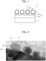
- FIG. 1 is a cross-sectional view schematically illustrating a steel sheet 1 for cans of the present embodiment.
- the steel sheet 1 for cans includes a steel sheet 2.
- the steel sheet 1 for cans further includes, on a surface of the steel sheet 2, two or more coating layers 3 and a chromium-containing layer 4 in this order from the steel sheet 2 side.
- FIG. 1 illustrates an example in which the coating layers 3 are two layers. That is, the steel sheet 1 for cans includes a coating layer 3a and a coating layer 3b.
- the coating layer 3a is, for example, a chromium metal layer as described below.
- the coating layer 3b is, for example, a chromium oxide layer as described below.
- the chromium-containing layer 4 is composed of a plurality of core-shell particles 5.
- the core-shell particles 5 are disposed on, of the coating layers 3, one layer (coating layer 3b) adjacent to the chromium-containing layer 4.
- the core-shell particles 5 each have a core 5a of chromium metal or a chromium compound and a shell 5b of chromium oxide covering the core.
- chrome oxide is present between the core 5a of the core-shell particle 5 and, of the coating layers 3, one layer (coating layer 3a) adjacent to the steel sheet 2.
- the core 5a is in non-contact with the coating layer 3a.
- chromium oxide is chromium oxide constituting the shell 5b, and may be chromium oxide constituting the coating layer 3b (chromium oxide layer).
- chromium compounds containing oxygen such as chromium hydrated oxide, chromium oxide, and chromium hydroxide are collectively referred to as "chromium oxide”.
- a cross section cut out using a focused ion beam was observed using a transmission electron microscope (TEM).
- FIG. 2 is a TEM image obtained by observing a cross section of the steel sheet 1 for cans of the present embodiment. Specifically, a bright field scanning transmission electron microscope (Bright-Field Scanning Transmission Electron Microscopy, BF-STEM) was used as the TEM.
- a bright field scanning transmission electron microscope Bright-Field Scanning Transmission Electron Microscopy, BF-STEM
- the core-shell particles 5 each having the core 5a and the shell 5b are disposed on the coating layer 3b.
- an element distribution in a thickness direction was determined using a three-dimensional atom probe (3DAP).
- FIG. 3 is a graph showing an element distribution in a thickness direction of the steel sheet 1 for cans of the present embodiment.
- the steel sheet 1 for cans has a configuration of the shell 5b (chromium oxide)/the core 5a (chromium metal)/the shell 5b (chromium oxide), the coating layer 3b (chromium oxide layer)/the coating layer 3a (chromium metal layer)/the steel sheet 2 from the outermost surface toward the steel sheet 2 in the thickness direction.
- FIG. 4 is a cross-sectional view schematically illustrating an example of a conventional steel sheet 11 for cans.
- the conventional steel sheet 11 for cans includes, on a surface of a steel sheet 12, a chromium metal layer 13 and a chromium oxide layer 14.
- the chromium metal layer 13 includes a flat plate-shaped base portion 13a and granular protrusions 13b.
- the chromium oxide layer 14 is disposed on the chromium metal layer 13 so as to follow the shape of the granular protrusions 13b.
- the base portion 13a and the granular protrusions 13b are in contact with each other, and there is no "chromium oxide" therebetween.
- the chromium metal layer 13 and the chromium oxide layer 14 covering the steel sheet 12 contribute to corrosion resistance.
- the granular protrusions 13b may be detached from the base portion 13a together with the chromium oxide layer 14 covering the granular protrusions 13b.
- chrome oxide is present between the core 5a of the core-shell particle 5 and the coating layer 3a, and the core 5a is in non-contact with the coating layer 3a.
- the steel sheet 1 for cans of the present embodiment is relatively more excellent in corrosion resistance than the conventional steel sheet 11 for cans (see FIG. 4 ).
- the type of the steel sheet is not particularly limited.
- steel sheets used as materials for containers for example, a low carbon steel sheet and an ultra low carbon steel sheet
- a manufacturing method, material, and the like of the steel sheet are also not particularly limited.
- the steel sheet is manufactured through a process starting with a typical billet manufacturing process, followed by such processes as hot rolling, pickling, cold rolling, annealing and temper rolling.
- Two or more coating layers are disposed on the surface of the steel sheet.
- the coating layers suppress surface exposure of the steel sheet and improve corrosion resistance.
- the coating layers are disposed on at least one surface of the steel sheet, and the coating layers may be disposed on both surfaces of the steel sheet.
- the number of coating layers is, for example, five or less and preferably three or less.
- the number of coating layers may be two.
- coating layer adjacent to the steel sheet may sometimes be referred to as “coating layer A”
- coating layer adjacent to the chromium-containing layer described below may sometimes be referred to as “coating layer B”.
- At least one of the coating layers is, for example, a chromium metal layer.
- the coating layer A adjacent to the steel sheet is preferably a chromium metal layer.
- Another layer of the coating layers is, for example, a metal layer or a metal oxide layer.
- the coating layer B adjacent to the chromium-containing layer is preferably a metal layer or a metal oxide layer, and particularly, a metal oxide layer is more preferable.
- Suitable examples of the metal element constituting the metal layer include metal elements nobler than Fe, such as Ni, Sn, Ag, Pt, and Au, from the viewpoint of obtaining sufficient corrosion resistance.
- Suitable examples of the metal oxide constituting the metal oxide layer include stable oxides such as Cr oxide (chromium oxide), Sn oxide, and Al oxide from the viewpoint of obtaining sufficient corrosion resistance, and among them, Cr oxide (chromium oxide) is more preferable. That is, the metal oxide layer is preferably a chromium oxide layer.
- a method for forming the metal layer is not particularly limited, and examples thereof include a method of electroplating using a known plating bath when the metal element constituting the metal layer is Ni, Sn, Ag, or the like.
- a method for forming the metal oxide layer is also not particularly limited.
- the metal layer may be naturally oxidized to obtain a metal oxide layer.
- the metal layer may be oxidized by performing an anodic electrolysis treatment in a plating bath or the like.
- the thickness of the coating layers is not particularly limited, and from the reason that the corrosion resistance is more excellent, the total thickness is preferably 3 nm or more and more preferably 5 nm or more.
- the upper limit is not particularly limited, but when the coating layers are excessively thick, this may cause cracking or peeling, so that the total thickness of the coating layers is preferably 1000 nm or less, more preferably 500 nm or less, even more preferably 200 nm or less, and particularly preferably 100 nm or less.
- the number and the thickness of the coating layers can be measured by observing a cross section cut out using FIB with the use of a transmission electron microscope (TEM). An average value of arbitrary five visual fields is used.
- TEM transmission electron microscope
- the core grain size and the shell thickness described below are also measured in the same manner.
- the chromium-containing layer is a layer composed of a plurality of core-shell particles.
- the core-shell particles are disposed on, of the coating layers, one layer (see “coating layer 3b" in FIG. 1 ) adjacent to the chromium-containing layer.
- the core of the core-shell particle is formed of chromium metal or a chromium compound.
- the shell covering the core is formed of chromium oxide.
- the core of the core-shell particle reduces the contact resistance between the steel sheets for cans and improves the weldability. An estimated mechanism by which the contact resistance is reduced is described below.
- the shell of the core-shell particle is formed of chromium oxide.
- one layer adjacent to the chromium-containing layer may also be a metal oxide layer such as chromium oxide layer.
- a metal oxide such as chromium oxide has a higher electrical resistance than chromium metal, and thus can be an inhibitor of welding.
- the cores of the core-shell particles destroy these metal oxides due to the surface pressure at the time of contact between the steel sheets for cans during welding, and become current-carrying points of welding current, and as a result, the contact resistance greatly decreases.
- the core of the core-shell particle is formed of chromium metal or a chromium compound.
- the chromium compound include chromium compounds other than chromium oxide, and specific examples thereof include Fe-Cr alloys, chromium carbide, chromium nitride, and chromium boride.
- the core is preferably formed of chromium metal from the reason that conductivity is high and weldability is more excellent.
- the chromium metal or the chromium compound constituting the core is preferably a single crystal from the reason that the single crystal has higher conductivity and more excellent weldability than a polycrystal.
- the grain size of the core is preferably 5 nm or more, more preferably 10 nm or more, even more preferably 25 nm or more, and particularly preferably 40 nm or more, from the reason that the metal oxide is easily broken effectively and weldability is more excellent.
- the upper limit of the core grain size is not particularly limited. However, when the core grain size is excessively large, the number of contact points decreases, and it may be difficult to effectively reduce the contact resistance. Therefore, the core grain size is preferably 5000 nm or less, more preferably 1000 nm or less, even more preferably 500 nm or less, and particularly preferably 250 nm or less.
- the chromium oxide constituting the shell is preferably amorphous. Since the shell is amorphous, defects are less likely to be introduced into the interface between the shell and the core, and the adhesion between the shell and the core is excellent.
- the thickness of the shell (shell thickness) formed of chromium oxide is large, welding is easily hindered as compared with a case where the thickness is small.
- the shell thickness is preferably 10.0 nm or less, more preferably 7.0 nm or less, even more preferably 5.0 nm or less, and particularly preferably 1.0 nm or less.
- the shell thickness is preferably 1/3 or less, more preferably 1/6 or less, and even more preferably 1/10 or less of the core grain size.
- the corrosion resistance becomes favorable as compared with a case where the thickness is small.
- the shell thickness is preferably 0.5 nm or more, preferably 1.0 nm or more, more preferably 3.0 nm or more, and even more preferably 5.0 nm or more.
- the area fraction of the core-shell particles is preferably 10% or more, more preferably 20% or more, and even more preferably 40% or more.
- the number density of the core-shell particles is preferably 1 particle/ ⁇ m 2 or more, more preferably 20 particles/ ⁇ m 2 or more, and even more preferably 50 particles/ ⁇ m 2 or more.
- the area fraction of the core-shell particles is preferably 90% or less, more preferably 85% or less, and even more preferably 80% or less.
- the number density of the core-shell particles is preferably 300 particles/ ⁇ m 2 or less, more preferably 240 particles/ ⁇ m 2 or less, and even more preferably 180 particles/ ⁇ m 2 or less.
- the core-shell particles are excessively elongated, when the steel sheets for cans are brought into contact with each other, the core-shell particles do not get stuck in the surface of the counterpart steel sheet for cans, and there is a high probability that reduction in contact resistance due to destruction of the metal oxide is not achieved.
- the aspect ratio of the core-shell particle is preferably 3.0 or less and more preferably 2.0 or less.
- the area fraction, the number density, and the aspect ratio of the core-shell particles are determined as follows.
- a photograph of a surface of the steel sheet for cans is taken at a magnification of 50,000 using a scanning electron microscope (SEM).
- the captured photograph is binarized using software (trade name: ImageJ) and subjected to image analysis to determine the area fraction (unit: %) and the number density (unit: particle(s)/ ⁇ m 2 ) of the core-shell particles occupying the surface of the steel sheet for cans.
- the aspect ratio (a/b) is obtained with the longest particle length as a major axis length "a" and the particle length at the time of longest crossing of the particle in the direction perpendicular thereto as a minor axis length "b".
- the coating weight of chromium metal is preferably 50 mg/m 2 or more, more preferably 60 mg/m 2 or more, and even more preferably 70 mg/m 2 or more.
- the coating weight is a coating weight per one surface of the steel sheet (the same applies hereinafter).
- the coating weight of chromium metal is preferably 200 mg/m 2 or less, more preferably 180 mg/m 2 or less, and even more preferably 160 mg/m 2 or less.
- the coating weight of chromium oxide in terms of chromium is preferably 3 mg/m 2 or more, more preferably 4 mg/m 2 or more, and even more preferably 5 mg/m 2 or more.
- chromium oxide is inferior to chromium metal in conductivity, and accordingly, too much amount of chromium oxide leads to excessive resistance in welding, which may cause generation of dust, occurrence of splash, and a variety of weld defects such as blowhole formation associated with overwelding, thus resulting in poor weldability of the steel sheet for cans.
- the coating weight of chromium oxide in terms of chromium is preferably 30 mg/m 2 or less, more preferably 20 mg/m 2 or less, and even more preferably 10 mg/m 2 or less.
- the coating weight of chromium metal and the coating weight of chromium oxide in terms of chromium are determined as follows.
- the amount of chromium (total amount of chromium) of the steel sheet for cans is measured using an X-ray fluorescence device.
- the steel sheet for cans is subjected to alkaline treatment, i.e., is immersed in a 6.5 N aqueous sodium hydroxide solution (liquid temperature: 90°C) for 10 minutes, and then the amount of chromium (the amount of chromium after alkaline treatment) is measured again using an X-ray fluorescence device.
- the amount of chromium after alkaline treatment is taken as the coating weight of chromium metal.
- the present manufacturing method is generally a method of subjecting a steel sheet to a primary cathodic electrolysis treatment, an anodic electrolysis treatment, a secondary cathodic electrolysis treatment, and a tertiary cathodic electrolysis treatment in this order with use of an aqueous solution containing a hexavalent chromium compound and a fluorine-containing compound.
- a current density of the secondary cathodic electrolysis treatment is 15 A/dm 2 or less, and an electric quantity density of the secondary cathodic electrolysis treatment is 5 C/dm 2 or less.
- chromium metal and chromium oxide are dissolved over the entire surface of the steel sheet at multiple sites. More specifically, it is assumed that in the anodic electrolysis treatment, chromium oxide is dissolved and becomes thin, and further, chromium metal in the lower layer is changed to chromium oxide.
- the deposition site is covered with chromium oxide so thinly that the deposition site is not crushed.
- chromium oxide forms a semiconductor of Cr 2 O 3 or the like to perform electron transfer; and chromium oxide is an extremely thin film, so that electrolytic deposition proceeds due to the tunneling effect.
- the base portion 13a is in contact with the granular protrusions 13b.
- the aqueous solution used in the manufacturing method of the present invention contains at least a hexavalent chromium compound and a fluorine-containing compound.
- hexavalent chromium compound examples include chromium trioxide (CrO 3 ); dichromates such as potassium dichromate (K 2 Cr 2 O 7 ); and chromates such as potassium chromate (K 2 CrO 4 ).
- the content of the hexavalent chromium compound in the aqueous solution is preferably 0.50 mol/L or more and more preferably 0.80 mol/L or more as the amount of Cr, from the reason that chromium metal can be stably deposited for a long time with high efficiency.
- the amount of Cr is preferably 5.00 mol/L or less and more preferably 3.00 mol/L or less.
- fluorine-containing compound examples include hydrofluoric acid (HF), potassium fluoride (KF), sodium fluoride (NaF), hydrosilicofluoric acid (H 2 SiF 6 ), and a salt of hydrosilicofluoric acid.
- Examples of the salt of hydrosilicofluoric acid include sodium silicofluoride (Na 2 SiF 6 ), potassium silicofluoride (K 2 SiF 6 ), and ammonium silicofluoride ((NH 4 ) 2 SiF 6 ).
- the content of the fluorine-containing compound in the aqueous solution is preferably more than 0.100 mol/L, more preferably 0.110 mol/L or more, even more preferably 0.150 mol/L or more, and particularly preferably 0.200 mol/L or more as the amount of F. With this, it is easy to obtain uniform and fine deposition sites on the entire surface at the time of dissolution in the anodic electrolysis treatment.
- the amount of F is preferably 4.000 mol/L or less, more preferably 3.000 mol/L or less, even more preferably 2.000 mol/L or less, and particularly preferably 1.000 mol/L or less.
- the adhesion efficiency of chromium metal is improved by using sulfuric acid in combination with the fluorine-containing compound.
- a part or all of sulfuric acid may be a sulfate such as sodium sulfate, calcium sulfate, or ammonium sulfate.
- the content of sulfuric acid in the aqueous solution is preferably 0.0001 mol/L or more, more preferably 0.0003 mol/L or more, and even more preferably 0.0010 mol/L or more as the amount of SO 4 2- .
- the amount of SO 4 2- is preferably 0.1000 mol/L or less and more preferably 0.0500 mol/L or less.
- the liquid temperature of the aqueous solution is preferably 20°C or higher, more preferably 30°C or higher, and even more preferably 40°C or higher.
- the liquid temperature of the aqueous solution is preferably 80°C or lower and more preferably 60°C or lower.
- each electrolysis treatment (the primary cathodic electrolysis treatment, the anodic electrolysis treatment, the secondary cathodic electrolysis treatment, and the tertiary cathodic electrolysis treatment), it is preferable to use only one kind of aqueous solution.
- the primary cathodic electrolysis treatment deposits chromium metal and chromium oxide.
- the electric quantity density (product of the current density and the current application time) of the primary cathodic electrolysis treatment is preferably 5.0 C/dm 2 or more, more preferably 8.0 C/dm 2 or more, and even more preferably 10.0 C/dm 2 or more.
- the electric quantity density of the primary cathodic electrolysis treatment is preferably 40.0 C/dm 2 or less, more preferably 35.0 C/dm 2 or less, and even more preferably 25.0 C/dm 2 or less.
- the current density (unit: A/dm 2 ) and the current application time (unit: s) of the primary cathodic electrolysis treatment are appropriately set from the above electric quantity density.
- the chromium metal and chromium oxide deposited in the primary cathodic electrolysis treatment are dissolved to form the above-described deposition site.
- the deposition site may decrease, the number density of the core-shell particles may decrease, the dissolution may proceed unevenly to generate a variation in distribution of the core-shell particles, or the thickness of the chromium metal layer may decrease.
- the electric quantity density (product of the current density and the current application time) of the anodic electrolysis treatment is preferably 0.1 C/dm 2 or more, more preferably more than 0.3 C/dm 2 , and even more preferably 0.8 C/dm 2 or more.
- the electric quantity density of the anodic electrolysis treatment is preferably 5.0 C/dm 2 or less, more preferably 3.0 C/dm 2 or less, and even more preferably 2.0 C/dm 2 or less.
- the current density (unit: A/dm 2 ) and the current application time (unit: s) of the anodic electrolysis treatment are appropriately set from the above electric quantity density.
- the deposition site formed in the anodic electrolysis treatment is thinly covered with chromium oxide. That is, the purpose of the secondary cathodic electrolysis treatment is not deposition of chromium metal.
- the deposition site is not covered with chromium oxide, and granular chromium metal is likely to be deposited from the deposition site.
- the current density of the secondary cathodic electrolysis treatment is 15 A/dm 2 or less, preferably 12 A/dm 2 or less, and more preferably 8 A/dm 2 or less.
- the electric quantity density of the secondary cathodic electrolysis treatment is 5.0 C/dm 2 or less, preferably 4.0 C/dm 2 or less, and more preferably 3.0 C/dm 2 or less.
- the lower limit of the current density of the secondary cathodic electrolysis treatment is not particularly limited, and is, for example, 1 A/dm 2 and preferably 3 A/dm 2 .
- the lower limit of the electric quantity density of the secondary cathodic electrolysis treatment is not particularly limited, and is, for example, 0.5 C/dm 2 and more preferably 1.0 C/dm 2 .
- the current application time (unit: s) of the secondary cathodic electrolysis treatment is appropriately set from the above current density and the above electric quantity density.
- chromium metal In the tertiary cathodic electrolysis treatment, granular chromium metal is deposited at a deposition site thinly covered with chromium oxide. In this way, chromium metal whose periphery is coated with chromium oxide (that is, core-shell particles) is produced.
- chromium oxide is also deposited, in this case, the thickness of the shell formed of chromium oxide is also easily increase.
- the current density of the tertiary cathodic electrolysis treatment is, for example, 20 A/dm 2 or more, preferably 30 A/dm 2 or more, more preferably 50 A/dm 2 or more, even more preferably 70 A/dm 2 or more, and particularly preferably 100 A/dm 2 or more.
- the electric quantity density of the tertiary cathodic electrolysis treatment is preferably 10.0 C/dm 2 or more, more preferably 15.0 C/dm 2 or more, even more preferably 20.0 C/dm 2 or more, and particularly preferably 25.0 C/dm 2 or more.
- the current density of the tertiary cathodic electrolysis treatment is preferably 250 A/dm 2 or less, more preferably 200 A/dm 2 or less, and even more preferably 150 A/dm 2 or less.
- the electric quantity density of the tertiary cathodic electrolysis treatment is preferably 100 C/dm 2 or less, more preferably 80 C/dm 2 or less, and even more preferably 60 C/dm 2 or less.
- the current application time (unit: s) of the tertiary cathodic electrolysis treatment is appropriately set from the above current density and the above electric quantity density.
- each electrolysis treatment need not be continuous electrolysis treatment. That is, each electrolysis treatment may be intermittent electrolysis treatment because electrolysis is carried out separately for each set of electrodes in industrial production and accordingly, an immersion period with no current application is inevitably present.
- the total electric quantity density preferably falls within the foregoing ranges.
- the steel sheet may be electrolessly immersed in an aqueous solution containing a hexavalent chromium compound for the purposes of controlling the amount of the chromium oxide layer, modifying that layer, and other purposes.
- a steel sheet (tempered grade: T4CA) as produced to a sheet thickness of 0.22 mm was subjected to normal degreasing and pickling.
- this steel sheet was subjected to the primary cathodic electrolysis treatment, the anodic electrolysis treatment, the secondary cathodic electrolysis treatment, and the tertiary cathodic electrolysis treatment using an aqueous solution shown in Table 1 below under the conditions shown in Table 2 below.
- Table 1 aqueous solution shown in Table 1 below under the conditions shown in Table 2 below.
- the aqueous solution was circulated by a pump at a rate equivalent to 100 mpm in a fluid cell, and a lead electrode was used.
- the steel sheet for cans as produced was rinsed with water and dried at room temperature using a blower.
- the coating weight of chromium metal and the coating weight of chromium oxide in terms of chromium were measured.
- the area fraction, the number density, the average grain size, the thickness of the shell, and the aspect ratio were measured.
- the cross section was observed by the above-described method and the element distribution in the thickness direction was determined.
- the produced steel sheet for cans had the following configuration (except for some comparative examples).
- Two test pieces were cut out from the produced steel sheet for cans, and the surface on which the coating layer and the chromium-containing layer were formed was used as an evaluation surface.
- the two test pieces were superposed such that the evaluation surfaces faced each other, and passed between metal rolls, and a surface pressure of 40 MPa was applied.
- test solution a mixed solution of 1.5 mass% citric acid and 1.5 mass% sodium chloride
- the peeled width (the total width of peeled portions extending to right and left from a crossing point) was measured at four places within 10 mm from the crossing point of the cross cut, and the average value of the peeled widths at the four places was determined.
- the average value of the peeled width was regarded as an under film corroded width and evaluated according to the following criteria. The case of "Superior”, “Excellent”, or “Good” was evaluated to be excellent in corrosion resistance.
- Two test pieces were cut out from the produced steel sheet for cans, and heated in a batch furnace. Specifically, heating of holding at a target plate temperature of 210°C for 10 minutes was performed twice. The two heated test pieces were superposed.
- the two superposed test pieces were sandwiched by using 1 mass% Cr-Cu electrodes of DR type (electrodes processed with a tip diameter of 6 mm and a curvature of R40 mm) and retained at a pressure of 1 kgf/cm 2 for 15 seconds.
- test pieces were energized at a current value of 10 A, and the resistance value (unit: ⁇ ) between the two test pieces was measured at 10 points.
- the average value of 10 points was taken as a contact resistance value to be evaluated according to the following criteria. The case of "Superior”, “Excellent”, or “Good” was evaluated to be excellent in weldability.
- Examples 1 to 15 were excellent in corrosion resistance and weldability, whereas Comparative Examples 1 to 3 were insufficient in corrosion resistance or weldability.
- Example 10 in which the current density of the tertiary cathodic electrolysis treatment was 105 A/dm 2 , as compared with Examples 7 to 9 and 11 in which the current density of the tertiary cathodic electrolysis treatment was lower, the shell thickness was large, and corrosion resistance was more favorable.
- Example 12 is an example in which the current density and the electric quantity density of the secondary cathodic electrolysis treatment are higher than those in Examples 1 to 11 and 13 to 15.
- Example 12 as above had a small shell thickness and more favorable weldability as compared with Examples 1 to 11 and 13 to 15.
- Example 13 to 15 the aqueous solutions B to D having different compositions from the aqueous solution A were used, but the same or similar results as in Examples 1 to 12 using the aqueous solution A were obtained.
- Comparative Example 1 is a comparative example in which the current density and the electric quantity density of the secondary cathodic electrolysis treatment are excessively high, and the tertiary cathodic electrolysis treatment is not performed.
- Comparative Example 2 is a comparative example in which the electric quantity density of the secondary cathodic electrolysis treatment is excessively high.
- Comparative Example 2 the core (granular chromium metal) was in contact with the coating layer A (chromium metal layer), and corrosion resistance was insufficient.
- Comparative Example 2 since the tertiary cathodic electrolysis treatment was performed, it is considered that chromium oxide was slightly formed on the granular chromium metal (core) at that time. Therefore, the shell thickness of Comparative Example 2 was 0.3 mm.
- Comparative Example 3 only the primary cathodic electrolysis treatment was performed. Therefore, a core (granular chromium metal) was not formed, and weldability was insufficient.
Landscapes
- Chemical & Material Sciences (AREA)
- Metallurgy (AREA)
- Engineering & Computer Science (AREA)
- Chemical Kinetics & Catalysis (AREA)
- Materials Engineering (AREA)
- Organic Chemistry (AREA)
- Electrochemistry (AREA)
- Inorganic Chemistry (AREA)
- Mechanical Engineering (AREA)
- Crystallography & Structural Chemistry (AREA)
- Other Surface Treatments For Metallic Materials (AREA)
- Electroplating Methods And Accessories (AREA)
- Electroplating And Plating Baths Therefor (AREA)
- Containers Having Bodies Formed In One Piece (AREA)
- Laminated Bodies (AREA)
Abstract
Description
- The present invention relates to a steel sheet for cans and a method of manufacturing the same.
-
Patent Literatures 1 and 2 disclose a steel sheet for cans including, "on a surface of a steel sheet, a chromium metal layer and a hydrated chromium oxide layer stacked in this order from a steel sheet side" in which the chromium metal layer further includes "granular protrusions". -
- Patent Literature 1:
WO 2018/225739 A - Patent Literature 2:
WO 2018/225726 A - The steel sheet for cans disclosed in
Patent Literatures 1 and 2 has favorable characteristics such as corrosion resistance and weldability, but in recent years, further improvement in corrosion resistance is required. - Therefore, an object of the present invention is to provide a steel sheet for cans having excellent corrosion resistance and excellent weldability, and a method of manufacturing the same.
- The present inventors have conducted intensive studies, and as a result, have found that the object is achieved by adopting the following configuration, thereby completing the present invention.
- That is, the present invention provides the following [1] to [14] .
- [1] A steel sheet for cans comprising,
- on a surface of a steel sheet, two or more coating layers and a chromium-containing layer stacked in this order from a steel sheet side,
- wherein the chromium-containing layer has a plurality of core-shell particles,
- the plurality of core-shell particles are disposed on, of the two or more coating layers, one layer adjacent to the chromium-containing layer, and
- each of the plurality of core-shell particles has a core of chromium metal or a chromium compound and a shell of chromium oxide covering the core.
- [2] The steel sheet for cans according to [1] above, wherein the core is in non-contact with, of the two or more coating layers, one layer adjacent to the steel sheet.
- [3] The steel sheet for cans according to [1] or [2] above, wherein chromium oxide is present between the core and, of the two or more coating layers, one layer adjacent to the steel sheet.
- [4] The steel sheet for cans according to any one of [1] to [3] above,
- wherein, of the two or more coating layers, one layer adjacent to the steel sheet is a chromium metal layer, and
- of the two or more coating layers, one layer adjacent to the chromium-containing layer is a metal layer or a metal oxide layer.
- [5] The steel sheet for cans according to [4] above,
- wherein, of the two or more coating layers, one layer adjacent to the chromium-containing layer is the metal oxide layer, and
- the metal oxide layer is a chromium oxide layer.
- [6] The steel sheet for cans according to any one of [1] to [5] above, wherein the two or more coating layers are two layers.
- [7] The steel sheet for cans according to any one of [1] to [6] above, wherein the core is formed of the chromium metal.
- [8] The steel sheet for cans according to any one of [1] to [7] above, wherein a coating weight of chromium metal is 50 to 200 mg/m2.
- [9] The steel sheet for cans according to any one of [1] to [8] above,
- wherein an area fraction of the plurality of core-shell particles is 10% or more, and
- a number density of the plurality of core-shell particles is 1 particle/µm2 or more.
- [10] The steel sheet for cans according to any one of [1] to [9] above,
- wherein a grain size of the core is 10 to 500 nm, and
- a thickness of the shell is 1/3 or less of the grain size of the core and is 0.5 to 10.0 nm.
- [11] The steel sheet for cans according to any one of [1] to [10] above, wherein an aspect ratio of each of the plurality of core-shell particles is 2.0 or less.
- [12] The steel sheet for cans according to any one of [1] to [11] above, wherein the core is a single crystal.
- [13] The steel sheet for cans according to any one of [1] to [12] above, wherein the shell is amorphous.
- [14] A method of manufacturing the steel sheet for cans according to any one of [1] to [13] above, the method comprising:
- subjecting a steel sheet to a primary cathodic electrolysis treatment, an anodic electrolysis treatment, a secondary cathodic electrolysis treatment, and a tertiary cathodic electrolysis treatment in this order with use of an aqueous solution containing a hexavalent chromium compound and a fluorine-containing compound,
- wherein a current density of the secondary cathodic electrolysis treatment is 15 A/dm2 or less, and an electric quantity density of the secondary cathodic electrolysis treatment is 5.0 C/dm2 or less.
- According to the present invention, it is possible to provide a steel sheet for cans having excellent corrosion resistance and excellent weldability, and a method of manufacturing the same.
-
- [
FIG. 1] FIG. 1 is a cross-sectional view schematically illustrating an example of a steel sheet for cans of the present embodiment. - [
FIG. 2] FIG. 2 is a TEM image obtained by observing a cross section of the steel sheet for cans of the present embodiment. - [
FIG. 3] FIG. 3 is a graph showing an element distribution in a thickness direction of the steel sheet for cans of the present embodiment. - [
FIG. 4] FIG. 4 is a cross-sectional view schematically illustrating an example of a conventional steel sheet for cans. -
FIG. 1 is a cross-sectional view schematically illustrating a steel sheet 1 for cans of the present embodiment. - As illustrated in
FIG. 1 , the steel sheet 1 for cans includes asteel sheet 2. The steel sheet 1 for cans further includes, on a surface of thesteel sheet 2, two ormore coating layers 3 and a chromium-containinglayer 4 in this order from thesteel sheet 2 side. -
FIG. 1 illustrates an example in which thecoating layers 3 are two layers. That is, the steel sheet 1 for cans includes acoating layer 3a and acoating layer 3b. Thecoating layer 3a is, for example, a chromium metal layer as described below. Thecoating layer 3b is, for example, a chromium oxide layer as described below. - The chromium-containing
layer 4 is composed of a plurality of core-shell particles 5. The core-shell particles 5 are disposed on, of thecoating layers 3, one layer (coating layer 3b) adjacent to the chromium-containinglayer 4. - The core-
shell particles 5 each have acore 5a of chromium metal or a chromium compound and ashell 5b of chromium oxide covering the core. - That is, in the steel sheet 1 for cans, "chromium oxide" is present between the
core 5a of the core-shell particle 5 and, of thecoating layers 3, one layer (coating layer 3a) adjacent to thesteel sheet 2. In other words, thecore 5a is in non-contact with thecoating layer 3a. - This "chromium oxide" is chromium oxide constituting the
shell 5b, and may be chromium oxide constituting thecoating layer 3b (chromium oxide layer). - In the present invention, chromium compounds containing oxygen such as chromium hydrated oxide, chromium oxide, and chromium hydroxide are collectively referred to as "chromium oxide".
- For the steel sheet 1 for cans of the present embodiment, a cross section cut out using a focused ion beam (FIB) was observed using a transmission electron microscope (TEM).
-
FIG. 2 is a TEM image obtained by observing a cross section of the steel sheet 1 for cans of the present embodiment. Specifically, a bright field scanning transmission electron microscope (Bright-Field Scanning Transmission Electron Microscopy, BF-STEM) was used as the TEM. - As viewing the TEM image of
FIG. 2 , it can be seen that the core-shell particles 5 each having thecore 5a and theshell 5b are disposed on thecoating layer 3b. - For the steel sheet 1 for cans of the present embodiment, an element distribution in a thickness direction was determined using a three-dimensional atom probe (3DAP).
-
FIG. 3 is a graph showing an element distribution in a thickness direction of the steel sheet 1 for cans of the present embodiment. - In the graph of
FIG. 3 , a composition of Cr-O/Cr/Cr-O/Cr/Fe is observed in order from the outermost surface toward the steel sheet. - From the above results, it can be seen that the steel sheet 1 for cans has a configuration of the
shell 5b (chromium oxide)/thecore 5a (chromium metal)/theshell 5b (chromium oxide), thecoating layer 3b (chromium oxide layer)/thecoating layer 3a (chromium metal layer)/thesteel sheet 2 from the outermost surface toward thesteel sheet 2 in the thickness direction. - That is, the above results demonstrate that "chromium oxide" is present between the core 5a and the
coating layer 3a, and thecore 5a is in non-contact with thecoating layer 3a. - A configuration of a conventional steel sheet for cans will be described.
-
FIG. 4 is a cross-sectional view schematically illustrating an example of aconventional steel sheet 11 for cans. - The
conventional steel sheet 11 for cans includes, on a surface of asteel sheet 12, achromium metal layer 13 and achromium oxide layer 14. - The
chromium metal layer 13 includes a flat plate-shapedbase portion 13a andgranular protrusions 13b. Thechromium oxide layer 14 is disposed on thechromium metal layer 13 so as to follow the shape of thegranular protrusions 13b. - In the
conventional steel sheet 11 for cans, thebase portion 13a and thegranular protrusions 13b are in contact with each other, and there is no "chromium oxide" therebetween. - The
chromium metal layer 13 and thechromium oxide layer 14 covering thesteel sheet 12 contribute to corrosion resistance. - When the surfaces of the
conventional steel sheet 11 for cans are brought into contact with each other or rubbed in a contact state, thegranular protrusions 13b may be detached from thebase portion 13a together with thechromium oxide layer 14 covering thegranular protrusions 13b. - In this case, at a portion where the
granular protrusions 13b are detached, only thebase portion 13a of thechromium metal layer 13 covers thesteel sheet 12, thesteel sheet 12 is easily exposed, and corrosion resistance may be insufficient as compared with the initial state. - On the other hand, in the steel sheet 1 for cans of the present embodiment described based on
FIGS. 1 to 3 , as described above, "chromium oxide" is present between the core 5a of the core-shell particle 5 and thecoating layer 3a, and thecore 5a is in non-contact with thecoating layer 3a. - Therefore, even if the core-
shell particles 5 are detached, not only thecoating layer 3a (chromium metal layer) but also "chromium oxide" such as thecoating layer 3b tends to remain at the portion, so that thesteel sheet 2 is hardly exposed. - Therefore, the steel sheet 1 for cans of the present embodiment is relatively more excellent in corrosion resistance than the
conventional steel sheet 11 for cans (seeFIG. 4 ). - Hereinafter, each constituent of the steel sheet for cans of the present embodiment will be described in more detail.
- The type of the steel sheet is not particularly limited. In general, steel sheets used as materials for containers (for example, a low carbon steel sheet and an ultra low carbon steel sheet) can be used. A manufacturing method, material, and the like of the steel sheet are also not particularly limited. The steel sheet is manufactured through a process starting with a typical billet manufacturing process, followed by such processes as hot rolling, pickling, cold rolling, annealing and temper rolling.
- Two or more coating layers are disposed on the surface of the steel sheet.
- The coating layers suppress surface exposure of the steel sheet and improve corrosion resistance.
- It suffices if the coating layers are disposed on at least one surface of the steel sheet, and the coating layers may be disposed on both surfaces of the steel sheet.
- The number of coating layers is, for example, five or less and preferably three or less. The number of coating layers may be two.
- When the number of coating layers is two, hereinafter, for the sake of convenience, the coating layer adjacent to the steel sheet (see "
coating layer 3a" inFIG. 1 ) may sometimes be referred to as "coating layer A", and the coating layer adjacent to the chromium-containing layer described below (see "coating layer 3b" inFIG. 1 ) may sometimes be referred to as "coating layer B". - At least one of the coating layers is, for example, a chromium metal layer.
- In particular, the coating layer A adjacent to the steel sheet is preferably a chromium metal layer.
- Another layer of the coating layers is, for example, a metal layer or a metal oxide layer.
- In particular, the coating layer B adjacent to the chromium-containing layer is preferably a metal layer or a metal oxide layer, and particularly, a metal oxide layer is more preferable.
- Suitable examples of the metal element constituting the metal layer include metal elements nobler than Fe, such as Ni, Sn, Ag, Pt, and Au, from the viewpoint of obtaining sufficient corrosion resistance.
- Suitable examples of the metal oxide constituting the metal oxide layer include stable oxides such as Cr oxide (chromium oxide), Sn oxide, and Al oxide from the viewpoint of obtaining sufficient corrosion resistance, and among them, Cr oxide (chromium oxide) is more preferable. That is, the metal oxide layer is preferably a chromium oxide layer.
- A method for forming the metal layer is not particularly limited, and examples thereof include a method of electroplating using a known plating bath when the metal element constituting the metal layer is Ni, Sn, Ag, or the like.
- A method for forming the metal oxide layer is also not particularly limited. For example, the metal layer may be naturally oxidized to obtain a metal oxide layer. The metal layer may be oxidized by performing an anodic electrolysis treatment in a plating bath or the like.
- The thickness of the coating layers is not particularly limited, and from the reason that the corrosion resistance is more excellent, the total thickness is preferably 3 nm or more and more preferably 5 nm or more.
- Meanwhile, the upper limit is not particularly limited, but when the coating layers are excessively thick, this may cause cracking or peeling, so that the total thickness of the coating layers is preferably 1000 nm or less, more preferably 500 nm or less, even more preferably 200 nm or less, and particularly preferably 100 nm or less.
- The number and the thickness of the coating layers can be measured by observing a cross section cut out using FIB with the use of a transmission electron microscope (TEM). An average value of arbitrary five visual fields is used.
- The core grain size and the shell thickness described below are also measured in the same manner.
- The chromium-containing layer is a layer composed of a plurality of core-shell particles.
- The core-shell particles are disposed on, of the coating layers, one layer (see "
coating layer 3b" inFIG. 1 ) adjacent to the chromium-containing layer. - The core of the core-shell particle is formed of chromium metal or a chromium compound. The shell covering the core is formed of chromium oxide.
- The core of the core-shell particle reduces the contact resistance between the steel sheets for cans and improves the weldability. An estimated mechanism by which the contact resistance is reduced is described below.
- The shell of the core-shell particle is formed of chromium oxide.
- As described above, of the coating layers, one layer (see "
coating layer 3b" inFIG. 1 ) adjacent to the chromium-containing layer may also be a metal oxide layer such as chromium oxide layer. - A metal oxide such as chromium oxide has a higher electrical resistance than chromium metal, and thus can be an inhibitor of welding.
- However, the cores of the core-shell particles destroy these metal oxides due to the surface pressure at the time of contact between the steel sheets for cans during welding, and become current-carrying points of welding current, and as a result, the contact resistance greatly decreases.
- As described above, the core of the core-shell particle is formed of chromium metal or a chromium compound. Examples of the chromium compound include chromium compounds other than chromium oxide, and specific examples thereof include Fe-Cr alloys, chromium carbide, chromium nitride, and chromium boride.
- The core is preferably formed of chromium metal from the reason that conductivity is high and weldability is more excellent.
- The chromium metal or the chromium compound constituting the core is preferably a single crystal from the reason that the single crystal has higher conductivity and more excellent weldability than a polycrystal.
- The grain size of the core (core grain size) is preferably 5 nm or more, more preferably 10 nm or more, even more preferably 25 nm or more, and particularly preferably 40 nm or more, from the reason that the metal oxide is easily broken effectively and weldability is more excellent.
- The upper limit of the core grain size is not particularly limited. However, when the core grain size is excessively large, the number of contact points decreases, and it may be difficult to effectively reduce the contact resistance. Therefore, the core grain size is preferably 5000 nm or less, more preferably 1000 nm or less, even more preferably 500 nm or less, and particularly preferably 250 nm or less.
- The chromium oxide constituting the shell is preferably amorphous. Since the shell is amorphous, defects are less likely to be introduced into the interface between the shell and the core, and the adhesion between the shell and the core is excellent.
- When the thickness of the shell (shell thickness) formed of chromium oxide is large, welding is easily hindered as compared with a case where the thickness is small.
- From the reason that weldability is more excellent, the shell thickness is preferably 10.0 nm or less, more preferably 7.0 nm or less, even more preferably 5.0 nm or less, and particularly preferably 1.0 nm or less.
- For the same reason, the shell thickness is preferably 1/3 or less, more preferably 1/6 or less, and even more preferably 1/10 or less of the core grain size.
- Meanwhile, when the thickness of the shell formed of chromium oxide is large, the corrosion resistance becomes favorable as compared with a case where the thickness is small.
- From the reason that the corrosion resistance is more excellent, the shell thickness is preferably 0.5 nm or more, preferably 1.0 nm or more, more preferably 3.0 nm or more, and even more preferably 5.0 nm or more.
- From the reason that the core-shell particles are likely to effectively destroy the metal oxide (particularly, the coating layer which is a metal oxide layer), the area fraction of the core-shell particles is preferably 10% or more, more preferably 20% or more, and even more preferably 40% or more.
- For the same reason, the number density of the core-shell particles is preferably 1 particle/µm2 or more, more preferably 20 particles/µm2 or more, and even more preferably 50 particles/µm2 or more.
- Meanwhile, when the core-shell particles excessively occupy the surface of the steel sheet for cans, the contact between the core-shell particles increases, and it may be difficult to contribute to the reduction of the contact resistance.
- Therefore, the area fraction of the core-shell particles is preferably 90% or less, more preferably 85% or less, and even more preferably 80% or less.
- The number density of the core-shell particles is preferably 300 particles/µm2 or less, more preferably 240 particles/µm2 or less, and even more preferably 180 particles/µm2 or less.
- In a case where the core-shell particles are excessively elongated, when the steel sheets for cans are brought into contact with each other, the core-shell particles do not get stuck in the surface of the counterpart steel sheet for cans, and there is a high probability that reduction in contact resistance due to destruction of the metal oxide is not achieved.
- Therefore, from the reason that weldability is more excellent, the aspect ratio of the core-shell particle is preferably 3.0 or less and more preferably 2.0 or less.
- The area fraction, the number density, and the aspect ratio of the core-shell particles are determined as follows.
- First, a photograph of a surface of the steel sheet for cans is taken at a magnification of 50,000 using a scanning electron microscope (SEM).
- The captured photograph is binarized using software (trade name: ImageJ) and subjected to image analysis to determine the area fraction (unit: %) and the number density (unit: particle(s)/µm2) of the core-shell particles occupying the surface of the steel sheet for cans.
- For each core-shell particle, the aspect ratio (a/b) is obtained with the longest particle length as a major axis length "a" and the particle length at the time of longest crossing of the particle in the direction perpendicular thereto as a minor axis length "b".
- In any cases, an average value of arbitrary five visual fields is used.
- From the reason that the corrosion resistance of the steel sheet for cans is more excellent, the coating weight of chromium metal is preferably 50 mg/m2 or more, more preferably 60 mg/m2 or more, and even more preferably 70 mg/m2 or more. The coating weight is a coating weight per one surface of the steel sheet (the same applies hereinafter).
- Meanwhile, when the coating weight of chromium metal is too large, high-melting-point chromium metal covers the entire surface of the steel sheet, and this induces significant decrease in weld strength in welding and significant generation of dust, which may lead to poor weldability.
- Therefore, from the reason that the weldability of the steel sheet for cans is more excellent, the coating weight of chromium metal is preferably 200 mg/m2 or less, more preferably 180 mg/m2 or less, and even more preferably 160 mg/m2 or less.
- From the reason that the corrosion resistance of the steel sheet for cans is more excellent, the coating weight of chromium oxide in terms of chromium is preferably 3 mg/m2 or more, more preferably 4 mg/m2 or more, and even more preferably 5 mg/m2 or more.
- Meanwhile, chromium oxide is inferior to chromium metal in conductivity, and accordingly, too much amount of chromium oxide leads to excessive resistance in welding, which may cause generation of dust, occurrence of splash, and a variety of weld defects such as blowhole formation associated with overwelding, thus resulting in poor weldability of the steel sheet for cans.
- Therefore, from the reason that the weldability of the steel sheet for cans is more excellent, the coating weight of chromium oxide in terms of chromium is preferably 30 mg/m2 or less, more preferably 20 mg/m2 or less, and even more preferably 10 mg/m2 or less.
- The coating weight of chromium metal and the coating weight of chromium oxide in terms of chromium are determined as follows.
- First, the amount of chromium (total amount of chromium) of the steel sheet for cans is measured using an X-ray fluorescence device. Next, the steel sheet for cans is subjected to alkaline treatment, i.e., is immersed in a 6.5 N aqueous sodium hydroxide solution (liquid temperature: 90°C) for 10 minutes, and then the amount of chromium (the amount of chromium after alkaline treatment) is measured again using an X-ray fluorescence device. The amount of chromium after alkaline treatment is taken as the coating weight of chromium metal.
- Thereafter, the equation (amount of alkali-soluble chromium) = (total amount of chromium) - (amount of chromium after alkaline treatment) is calculated, and the amount of alkali-soluble chromium is taken as the coating weight of chromium oxide in terms of chromium.
- Next, a method of manufacturing the steel sheet for cans of the present embodiment described above will be described.
- In the following, a method of manufacturing a steel sheet for cans satisfying the following conditions (also referred to as "present manufacturing method" for convenience) will be described.
- · Number of coating layers: 2
- · Coating layer A adjacent to the steel sheet: chromium metal layer
- · Coating layer B adjacent to the chromium-containing layer: chromium oxide layer
- · Core of the core-shell particle: chromium metal
- · Shell of the core-shell particle: chromium oxide
- The present manufacturing method is generally a method of subjecting a steel sheet to a primary cathodic electrolysis treatment, an anodic electrolysis treatment, a secondary cathodic electrolysis treatment, and a tertiary cathodic electrolysis treatment in this order with use of an aqueous solution containing a hexavalent chromium compound and a fluorine-containing compound.
- In the present manufacturing method, a current density of the secondary cathodic electrolysis treatment is 15 A/dm2 or less, and an electric quantity density of the secondary cathodic electrolysis treatment is 5 C/dm2 or less.
- When the steel sheet is subjected to the cathodic electrolysis treatment in an aqueous solution containing a hexavalent chromium compound, a reduction reaction occurs on the surface of the steel sheet, and chromium metal and chromium oxide, which is an intermediate product to chromium metal, are deposited on the surface.
- Since the anodic electrolysis treatment is performed between the two cathodic electrolysis treatments, chromium metal and chromium oxide are dissolved over the entire surface of the steel sheet at multiple sites. More specifically, it is assumed that in the anodic electrolysis treatment, chromium oxide is dissolved and becomes thin, and further, chromium metal in the lower layer is changed to chromium oxide.
- Thereafter, when the cathodic electrolysis treatment is performed to deposit chromium metal, a current concentrates on a portion where chromium oxide is thin (deposition site), and granular chromium metal is generated.
- In the present manufacturing method, by performing the secondary cathodic electrolysis treatment under appropriate conditions (low current density and low electric quantity density), the deposition site is covered with chromium oxide so thinly that the deposition site is not crushed.
- As a result, in the subsequent tertiary cathodic electrolysis treatment, granular chromium metal (that is, core-shell particles) whose periphery is coated with chromium oxide is deposited at the deposition site.
- The mechanism (reason) by which chromium metal is deposited (electrolytically deposited) on chromium oxide formed thin is not clear in detail, but reasons are considered as follows, for example: chromium oxide forms a semiconductor of Cr2O3 or the like to perform electron transfer; and chromium oxide is an extremely thin film, so that electrolytic deposition proceeds due to the tunneling effect.
- When the secondary cathodic electrolysis treatment is not performed (or the secondary cathodic electrolysis treatment is not performed under appropriate conditions), granular chromium metal grows directly from the deposition site.
- In this case, specifically, for example, like the
conventional steel sheet 11 for cans described with reference toFIG. 4 , thebase portion 13a is in contact with thegranular protrusions 13b. - Hereinafter, the aqueous solution and each electrolysis treatment used in the present manufacturing method will be described in detail.
- The aqueous solution used in the manufacturing method of the present invention contains at least a hexavalent chromium compound and a fluorine-containing compound.
- Examples of the hexavalent chromium compound include chromium trioxide (CrO3); dichromates such as potassium dichromate (K2Cr2O7); and chromates such as potassium chromate (K2CrO4).
- The content of the hexavalent chromium compound in the aqueous solution is preferably 0.50 mol/L or more and more preferably 0.80 mol/L or more as the amount of Cr, from the reason that chromium metal can be stably deposited for a long time with high efficiency.
- Meanwhile, the amount of Cr is preferably 5.00 mol/L or less and more preferably 3.00 mol/L or less.
- Examples of the fluorine-containing compound include hydrofluoric acid (HF), potassium fluoride (KF), sodium fluoride (NaF), hydrosilicofluoric acid (H2SiF6), and a salt of hydrosilicofluoric acid.
- Examples of the salt of hydrosilicofluoric acid include sodium silicofluoride (Na2SiF6), potassium silicofluoride (K2SiF6), and ammonium silicofluoride ((NH4)2SiF6).
- The content of the fluorine-containing compound in the aqueous solution is preferably more than 0.100 mol/L, more preferably 0.110 mol/L or more, even more preferably 0.150 mol/L or more, and particularly preferably 0.200 mol/L or more as the amount of F. With this, it is easy to obtain uniform and fine deposition sites on the entire surface at the time of dissolution in the anodic electrolysis treatment.
- Meanwhile, the amount of F is preferably 4.000 mol/L or less, more preferably 3.000 mol/L or less, even more preferably 2.000 mol/L or less, and particularly preferably 1.000 mol/L or less.
- The adhesion efficiency of chromium metal is improved by using sulfuric acid in combination with the fluorine-containing compound.
- A part or all of sulfuric acid may be a sulfate such as sodium sulfate, calcium sulfate, or ammonium sulfate.
- The content of sulfuric acid in the aqueous solution is preferably 0.0001 mol/L or more, more preferably 0.0003 mol/L or more, and even more preferably 0.0010 mol/L or more as the amount of SO4 2-.
- Meanwhile, the amount of SO4 2- is preferably 0.1000 mol/L or less and more preferably 0.0500 mol/L or less.
- The liquid temperature of the aqueous solution is preferably 20°C or higher, more preferably 30°C or higher, and even more preferably 40°C or higher.
- Meanwhile, the liquid temperature of the aqueous solution is preferably 80°C or lower and more preferably 60°C or lower.
- In each electrolysis treatment (the primary cathodic electrolysis treatment, the anodic electrolysis treatment, the secondary cathodic electrolysis treatment, and the tertiary cathodic electrolysis treatment), it is preferable to use only one kind of aqueous solution.
- The primary cathodic electrolysis treatment deposits chromium metal and chromium oxide.
- At this time, from the viewpoint of achieving an appropriate deposition amount, the electric quantity density (product of the current density and the current application time) of the primary cathodic electrolysis treatment is preferably 5.0 C/dm2 or more, more preferably 8.0 C/dm2 or more, and even more preferably 10.0 C/dm2 or more.
- Meanwhile, the electric quantity density of the primary cathodic electrolysis treatment is preferably 40.0 C/dm2 or less, more preferably 35.0 C/dm2 or less, and even more preferably 25.0 C/dm2 or less.
- The current density (unit: A/dm2) and the current application time (unit: s) of the primary cathodic electrolysis treatment are appropriately set from the above electric quantity density.
- In the anodic electrolysis treatment, the chromium metal and chromium oxide deposited in the primary cathodic electrolysis treatment are dissolved to form the above-described deposition site.
- At this time, when the dissolution in the anodic electrolysis treatment is too strong or too weak, the deposition site may decrease, the number density of the core-shell particles may decrease, the dissolution may proceed unevenly to generate a variation in distribution of the core-shell particles, or the thickness of the chromium metal layer may decrease.
- From the above viewpoint, the electric quantity density (product of the current density and the current application time) of the anodic electrolysis treatment is preferably 0.1 C/dm2 or more, more preferably more than 0.3 C/dm2, and even more preferably 0.8 C/dm2 or more.
- Meanwhile, the electric quantity density of the anodic electrolysis treatment is preferably 5.0 C/dm2 or less, more preferably 3.0 C/dm2 or less, and even more preferably 2.0 C/dm2 or less.
- The current density (unit: A/dm2) and the current application time (unit: s) of the anodic electrolysis treatment are appropriately set from the above electric quantity density.
- In the secondary cathodic electrolysis treatment, as described above, the deposition site formed in the anodic electrolysis treatment is thinly covered with chromium oxide. That is, the purpose of the secondary cathodic electrolysis treatment is not deposition of chromium metal.
- When the current density and/or the electric quantity density of the secondary cathodic electrolysis treatment is too high, the deposition site is not covered with chromium oxide, and granular chromium metal is likely to be deposited from the deposition site.
- Therefore, the current density of the secondary cathodic electrolysis treatment is 15 A/dm2 or less, preferably 12 A/dm2 or less, and more preferably 8 A/dm2 or less.
- The electric quantity density of the secondary cathodic electrolysis treatment is 5.0 C/dm2 or less, preferably 4.0 C/dm2 or less, and more preferably 3.0 C/dm2 or less.
- The lower limit of the current density of the secondary cathodic electrolysis treatment is not particularly limited, and is, for example, 1 A/dm2 and preferably 3 A/dm2.
- The lower limit of the electric quantity density of the secondary cathodic electrolysis treatment is not particularly limited, and is, for example, 0.5 C/dm2 and more preferably 1.0 C/dm2.
- The current application time (unit: s) of the secondary cathodic electrolysis treatment is appropriately set from the above current density and the above electric quantity density.
- In the tertiary cathodic electrolysis treatment, granular chromium metal is deposited at a deposition site thinly covered with chromium oxide. In this way, chromium metal whose periphery is coated with chromium oxide (that is, core-shell particles) is produced.
- In the tertiary cathodic electrolysis treatment, when the current density and/or the electric quantity density is high, granular chromium metal is easily deposited. In the tertiary cathodic electrolysis treatment, since chromium oxide is also deposited, in this case, the thickness of the shell formed of chromium oxide is also easily increase.
- From the above points, the current density of the tertiary cathodic electrolysis treatment is, for example, 20 A/dm2 or more, preferably 30 A/dm2 or more, more preferably 50 A/dm2 or more, even more preferably 70 A/dm2 or more, and particularly preferably 100 A/dm2 or more.
- Similarly, the electric quantity density of the tertiary cathodic electrolysis treatment is preferably 10.0 C/dm2 or more, more preferably 15.0 C/dm2 or more, even more preferably 20.0 C/dm2 or more, and particularly preferably 25.0 C/dm2 or more.
- Meanwhile, the current density of the tertiary cathodic electrolysis treatment is preferably 250 A/dm2 or less, more preferably 200 A/dm2 or less, and even more preferably 150 A/dm2 or less.
- The electric quantity density of the tertiary cathodic electrolysis treatment is preferably 100 C/dm2 or less, more preferably 80 C/dm2 or less, and even more preferably 60 C/dm2 or less.
- The current application time (unit: s) of the tertiary cathodic electrolysis treatment is appropriately set from the above current density and the above electric quantity density.
- Each electrolysis treatment need not be continuous electrolysis treatment. That is, each electrolysis treatment may be intermittent electrolysis treatment because electrolysis is carried out separately for each set of electrodes in industrial production and accordingly, an immersion period with no current application is inevitably present. In the case of intermittent electrolysis treatment, the total electric quantity density preferably falls within the foregoing ranges.
- After the tertiary cathodic electrolysis treatment, the steel sheet may be electrolessly immersed in an aqueous solution containing a hexavalent chromium compound for the purposes of controlling the amount of the chromium oxide layer, modifying that layer, and other purposes.
- Hereinafter, the present invention will be specifically described with reference to Examples. However, the present invention is not limited to the following Examples.
- A steel sheet (tempered grade: T4CA) as produced to a sheet thickness of 0.22 mm was subjected to normal degreasing and pickling.
- Subsequently, this steel sheet was subjected to the primary cathodic electrolysis treatment, the anodic electrolysis treatment, the secondary cathodic electrolysis treatment, and the tertiary cathodic electrolysis treatment using an aqueous solution shown in Table 1 below under the conditions shown in Table 2 below. When any of the electrolysis treatments was not performed, "-" was put in the corresponding space in Table 2 below.
- In each electrolysis treatment, the aqueous solution was circulated by a pump at a rate equivalent to 100 mpm in a fluid cell, and a lead electrode was used.
- In this way, a steel sheet for cans was produced. The steel sheet for cans as produced was rinsed with water and dried at room temperature using a blower.
- For the produced steel sheet for cans, the coating weight of chromium metal and the coating weight of chromium oxide in terms of chromium (simply referred to as "coating weight" in Table 2 below) were measured.
- For the core-shell particles of the produced steel sheet for cans, the area fraction, the number density, the average grain size, the thickness of the shell, and the aspect ratio were measured.
- The measurement methods are as described above. The results are shown in Table 2 below.
- When any of the measurements was not performed, "-" was put in Table 2 below (the same applies hereinafter).
- For the produced steel sheet for cans, the cross section was observed by the above-described method and the element distribution in the thickness direction was determined.
- As a result, it was be confirmed that the produced steel sheet for cans had the following configuration (except for some comparative examples).
- . Number of coating layers: 2
- · Coating layer A adjacent to the steel sheet: chromium metal layer
- · Coating layer B adjacent to the chromium-containing layer: chromium oxide layer
- · Core of the core-shell particle: chromium metal
- · Shell of the core-shell particle: chromium oxide
- For the produced steel sheet for cans, when "chromium oxide" was present between the core (granular chromium metal) and the coating layer A (chromium metal layer) and the core was in non-contact with the coating layer A, "Non-contact" was put in the column of "Contact state" in Table 2 below.
- Meanwhile, when the core (granular chromium metal) was in contact with the coating layer A (chromium metal layer), "Contact" was put in the column of "Contact state" in Table 2 below.
- The corrosion resistance and weldability of the produced steel sheet for cans were evaluated by performing the following tests. The results are shown in Table 2 below.
- Two test pieces were cut out from the produced steel sheet for cans, and the surface on which the coating layer and the chromium-containing layer were formed was used as an evaluation surface. The two test pieces were superposed such that the evaluation surfaces faced each other, and passed between metal rolls, and a surface pressure of 40 MPa was applied.
- Thereafter, an epoxy-phenol resin was applied to the evaluation surface of one test piece, and a heat treatment of heating at 210°C for 10 minutes was performed twice to form a coating film.
- Next, a cross cut having a depth reaching the steel sheet was formed in the coating film, and then the test piece was immersed in a test solution (a mixed solution of 1.5 mass% citric acid and 1.5 mass% sodium chloride) at 45°C for 72 hours. After immersion, the test piece was taken out from the test solution, washed and dried, and then a test of peeling off the coating film using a tape was performed.
- The peeled width (the total width of peeled portions extending to right and left from a crossing point) was measured at four places within 10 mm from the crossing point of the cross cut, and the average value of the peeled widths at the four places was determined. The average value of the peeled width was regarded as an under film corroded width and evaluated according to the following criteria. The case of "Superior", "Excellent", or "Good" was evaluated to be excellent in corrosion resistance.
- Superior: A corroded width of 0.5 mm or less
- Excellent: A corroded width of more than 0.5 mm and 1.0 mm or less
- Good: A corroded width of more than 1.0 mm and 2.0 mm or less
- Fair: A corroded width of more than 2.0 mm and 3.0 mm or less
- Poor: A corroded width of more than 3.0 mm
- Two test pieces were cut out from the produced steel sheet for cans, and heated in a batch furnace. Specifically, heating of holding at a target plate temperature of 210°C for 10 minutes was performed twice. The two heated test pieces were superposed.
- Subsequently, the two superposed test pieces were sandwiched by using 1 mass% Cr-Cu electrodes of DR type (electrodes processed with a tip diameter of 6 mm and a curvature of R40 mm) and retained at a pressure of 1 kgf/cm2 for 15 seconds.
- Thereafter, the test pieces were energized at a current value of 10 A, and the resistance value (unit: µΩ) between the two test pieces was measured at 10 points. The average value of 10 points was taken as a contact resistance value to be evaluated according to the following criteria. The case of "Superior", "Excellent", or "Good" was evaluated to be excellent in weldability.
- Superior: A contact resistance value of 50 µΩ or less
- Excellent: A contact resistance value of more than 50 µΩ and 100 µΩ or less
- Good: A contact resistance value of more than 100 µΩ and 300 µΩ or less
- Fair: A contact resistance value of more than 300 µΩ and 1000 µΩ or less
- Poor: A contact resistance value of more than 1000 µΩ
-
Table 1 Aqueous solution Composition Whole mol/L Cr F SO4 2- A CrO3: 180 g/L 1.80 0.207 0.0102 Na2SiF6: 6.5 g/L H2SO4: 1.0 g/L B CrO3: 100 g/L 1.00 0.160 0.0102 Na2SiF6: 5 g/L H2SO4: 1.0 g/L C CrO3: 55 g/L 0.55 0.112 0.0102 Na2SiF6: 3.5 g/L H2SO4: 1.0 g/L D CrO3: 195 g/L 1.95 0.207 0.0102 Na2SiF6: 6.5 g/L H2SO4: 1.0 g/L -

- As shown in Table 2 above, Examples 1 to 15 were excellent in corrosion resistance and weldability, whereas Comparative Examples 1 to 3 were insufficient in corrosion resistance or weldability.
- More specifically, the following results were obtained.
- In Examples 1 to 6, the conditions of the anodic electrolysis treatment are different from each other.
- Among them, in Examples 3 and 4 in which the electric quantity density of the anodic electrolysis treatment was within a range of 1.0 to 2.0 C/dm2, as compared with Examples 1, 2, 5, and 6 in which the electric quantity density was out of this range, a result was obtained in which the area fraction and the number density of the core-shell particles were high.
- In Examples 7 to 11, the conditions of the tertiary cathodic electrolysis treatment are different from each other.
- Among them, in Example 10 in which the current density of the tertiary cathodic electrolysis treatment was 105 A/dm2, as compared with Examples 7 to 9 and 11 in which the current density of the tertiary cathodic electrolysis treatment was lower, the shell thickness was large, and corrosion resistance was more favorable.
- Example 12 is an example in which the current density and the electric quantity density of the secondary cathodic electrolysis treatment are higher than those in Examples 1 to 11 and 13 to 15.
- Example 12 as above had a small shell thickness and more favorable weldability as compared with Examples 1 to 11 and 13 to 15.
- In Examples 13 to 15, the aqueous solutions B to D having different compositions from the aqueous solution A were used, but the same or similar results as in Examples 1 to 12 using the aqueous solution A were obtained.
- Comparative Example 1 is a comparative example in which the current density and the electric quantity density of the secondary cathodic electrolysis treatment are excessively high, and the tertiary cathodic electrolysis treatment is not performed.
- In Comparative Example 1 as above, the core (granular chromium metal) was in contact with the coating layer A (chromium metal layer), and corrosion resistance was insufficient.
- Comparative Example 2 is a comparative example in which the electric quantity density of the secondary cathodic electrolysis treatment is excessively high.
- In Comparative Example 2, the core (granular chromium metal) was in contact with the coating layer A (chromium metal layer), and corrosion resistance was insufficient.
- In Comparative Example 2, since the tertiary cathodic electrolysis treatment was performed, it is considered that chromium oxide was slightly formed on the granular chromium metal (core) at that time. Therefore, the shell thickness of Comparative Example 2 was 0.3 mm.
- In Comparative Example 3, only the primary cathodic electrolysis treatment was performed. Therefore, a core (granular chromium metal) was not formed, and weldability was insufficient.
-
- 1: steel sheet for cans
- 2: steel sheet
- 3, 3a, 3b: coating layer
- 4: chromium-containing layer
- 5: core-shell particle
- 5a: core
- 5b: shell
- 11: conventional steel sheet for cans
- 12: steel sheet
- 13: chromium metal layer
- 14: chromium oxide layer
- 13a: base portion
- 13b: granular protrusion
Claims (14)
- A steel sheet for cans comprising,on a surface of a steel sheet, two or more coating layers and a chromium-containing layer stacked in this order from a steel sheet side,wherein the chromium-containing layer has a plurality of core-shell particles,the plurality of core-shell particles are disposed on, of the two or more coating layers, one layer adjacent to the chromium-containing layer, andeach of the plurality of core-shell particles has a core of chromium metal or a chromium compound and a shell of chromium oxide covering the core.
- The steel sheet for cans according to claim 1,
wherein the core is in non-contact with, of the two or more coating layers, one layer adjacent to the steel sheet. - The steel sheet for cans according to claim 1 or 2, wherein chromium oxide is present between the core and, of the two or more coating layers, one layer adjacent to the steel sheet.
- The steel sheet for cans according to any one of claims 1 to 3,wherein, of the two or more coating layers, one layer adjacent to the steel sheet is a chromium metal layer, andof the two or more coating layers, one layer adjacent to the chromium-containing layer is a metal layer or a metal oxide layer.
- The steel sheet for cans according to claim 4,wherein, of the two or more coating layers, one layer adjacent to the chromium-containing layer is the metal oxide layer, andthe metal oxide layer is a chromium oxide layer.
- The steel sheet for cans according to any one of claims 1 to 5, wherein the two or more coating layers are two layers.
- The steel sheet for cans according to any one of claims 1 to 6, wherein the core is formed of the chromium metal.
- The steel sheet for cans according to any one of claims 1 to 7, wherein a coating weight of chromium metal is 50 to 200 mg/m2.
- The steel sheet for cans according to any one of claims 1 to 8,wherein an area fraction of the plurality of core-shell particles is 10% or more, anda number density of the plurality of core-shell particles is 1 particle/µm2 or more.
- The steel sheet for cans according to any one of claims 1 to 9,wherein a grain size of the core is 10 to 500 nm, anda thickness of the shell is 1/3 or less of the grain size of the core and is 0.5 to 10.0 nm.
- The steel sheet for cans according to any one of claims 1 to 10, wherein an aspect ratio of each of the plurality of core-shell particles is 2.0 or less.
- The steel sheet for cans according to any one of claims 1 to 11, wherein the core is a single crystal.
- The steel sheet for cans according to any one of claims 1 to 12, wherein the shell is amorphous.
- A method of manufacturing the steel sheet for cans according to any one of claims 1 to 13, the method comprising:subjecting a steel sheet to a primary cathodic electrolysis treatment, an anodic electrolysis treatment, a secondary cathodic electrolysis treatment, and a tertiary cathodic electrolysis treatment in this order with use of an aqueous solution containing a hexavalent chromium compound and a fluorine-containing compound,wherein a current density of the secondary cathodic electrolysis treatment is 15 A/dm2 or less, and an electric quantity density of the secondary cathodic electrolysis treatment is 5.0 C/dm2 or less.
Applications Claiming Priority (2)
| Application Number | Priority Date | Filing Date | Title |
|---|---|---|---|
| JP2021202388A JP7306441B2 (en) | 2021-12-14 | 2021-12-14 | Steel plate for can and manufacturing method thereof |
| PCT/JP2022/038776 WO2023112467A1 (en) | 2021-12-14 | 2022-10-18 | Steel sheet for cans and method for producing same |
Publications (2)
| Publication Number | Publication Date |
|---|---|
| EP4421215A1 true EP4421215A1 (en) | 2024-08-28 |
| EP4421215A4 EP4421215A4 (en) | 2025-03-05 |
Family
ID=86774371
Family Applications (1)
| Application Number | Title | Priority Date | Filing Date |
|---|---|---|---|
| EP22907002.4A Pending EP4421215A4 (en) | 2021-12-14 | 2022-10-18 | STEEL SHEET FOR CANS AND ITS PRODUCTION METHOD |
Country Status (7)
| Country | Link |
|---|---|
| US (1) | US20250043456A1 (en) |
| EP (1) | EP4421215A4 (en) |
| JP (1) | JP7306441B2 (en) |
| KR (1) | KR20240089713A (en) |
| CN (1) | CN118382729A (en) |
| TW (1) | TWI839954B (en) |
| WO (1) | WO2023112467A1 (en) |
Family Cites Families (9)
| Publication number | Priority date | Publication date | Assignee | Title |
|---|---|---|---|---|
| JPS61213398A (en) * | 1985-03-15 | 1986-09-22 | Kawasaki Steel Corp | Tin-free steel sheet for welded can and its production |
| JPS6335797A (en) * | 1986-07-31 | 1988-02-16 | Nippon Kokan Kk <Nkk> | Manufacturing method of electrolytic chromate treated steel sheet with excellent weldability |
| JPH01252798A (en) * | 1988-03-31 | 1989-10-09 | Nkk Corp | Production of electrolytic chromate treated steel sheet for welded can |
| JPH03229897A (en) * | 1990-02-05 | 1991-10-11 | Kawasaki Steel Corp | Tin-free steel sheet for welded can high in surface brilliance and its production |
| MY111396A (en) * | 1990-12-26 | 2000-04-29 | Nippon Kokan Kk | Surface treated steel sheet for welded cans |
| ES2950567T3 (en) * | 2017-06-09 | 2023-10-11 | Jfe Steel Corp | Can steel sheet production method |
| CA3064024C (en) * | 2017-06-09 | 2022-02-15 | Jfe Steel Corporation | Steel sheet for cans, and production method therefor |
| JP6787500B2 (en) * | 2018-08-29 | 2020-11-18 | Jfeスチール株式会社 | Steel sheet for cans and its manufacturing method |
| WO2022163073A1 (en) * | 2021-01-27 | 2022-08-04 | Jfeスチール株式会社 | Can steel sheet and method for producing same |
-
2021
- 2021-12-14 JP JP2021202388A patent/JP7306441B2/en active Active
-
2022
- 2022-10-18 WO PCT/JP2022/038776 patent/WO2023112467A1/en not_active Ceased
- 2022-10-18 CN CN202280082399.5A patent/CN118382729A/en active Pending
- 2022-10-18 EP EP22907002.4A patent/EP4421215A4/en active Pending
- 2022-10-18 US US18/718,518 patent/US20250043456A1/en active Pending
- 2022-10-18 KR KR1020247015926A patent/KR20240089713A/en active Pending
- 2022-11-21 TW TW111144340A patent/TWI839954B/en active
Also Published As
| Publication number | Publication date |
|---|---|
| CN118382729A (en) | 2024-07-23 |
| TW202328495A (en) | 2023-07-16 |
| WO2023112467A1 (en) | 2023-06-22 |
| US20250043456A1 (en) | 2025-02-06 |
| JP7306441B2 (en) | 2023-07-11 |
| TWI839954B (en) | 2024-04-21 |
| EP4421215A4 (en) | 2025-03-05 |
| JP2023087864A (en) | 2023-06-26 |
| KR20240089713A (en) | 2024-06-20 |
Similar Documents
| Publication | Publication Date | Title |
|---|---|---|
| EP4269660A1 (en) | Can steel sheet and method for producing same | |
| JP5884947B2 (en) | Ni-plated steel sheet and method for producing Ni-plated steel sheet | |
| EP3388548B1 (en) | Steel sheet for cans and production method for steel sheet for cans | |
| JP7067543B2 (en) | Steel sheet for cans and its manufacturing method | |
| EP3620553B1 (en) | Production method for steel sheet for cans | |
| KR102888545B1 (en) | Surface-treated steel sheet and method of producing the same | |
| KR102313041B1 (en) | Steel plate for cans and manufacturing method thereof | |
| TW202009136A (en) | Steel sheet for cans, and method for producing same | |
| JP7327718B1 (en) | Surface-treated steel sheet and manufacturing method thereof | |
| US12325928B2 (en) | Roughened nickel-plated sheet | |
| EP4421215A1 (en) | Steel sheet for cans and method for producing same | |
| KR102904199B1 (en) | Surface-treated steel sheet and method of producing the same | |
| JP6197778B2 (en) | Steel plate for container and method for producing the same | |
| TWI902635B (en) | Surface treated steel plate and manufacturing method thereof | |
| JP7563660B1 (en) | Steel sheets for cans | |
| TWI902634B (en) | Surface treated steel plate and manufacturing method thereof | |
| TWI845179B (en) | Surface treated steel plate and manufacturing method thereof | |
| TW202544297A (en) | Surface treated steel plate | |
| TW202544298A (en) | Surface treated steel plate | |
| KR20260002883A (en) | Steel plate for cans | |
| WO2024257413A1 (en) | Steel sheet for can | |
| JP2004265694A (en) | Fuel cell separator | |
| JP6048441B2 (en) | Steel plate for containers |
Legal Events
| Date | Code | Title | Description |
|---|---|---|---|
| STAA | Information on the status of an ep patent application or granted ep patent |
Free format text: STATUS: THE INTERNATIONAL PUBLICATION HAS BEEN MADE |
|
| PUAI | Public reference made under article 153(3) epc to a published international application that has entered the european phase |
Free format text: ORIGINAL CODE: 0009012 |
|
| STAA | Information on the status of an ep patent application or granted ep patent |
Free format text: STATUS: REQUEST FOR EXAMINATION WAS MADE |
|
| 17P | Request for examination filed |
Effective date: 20240522 |
|
| AK | Designated contracting states |
Kind code of ref document: A1 Designated state(s): AL AT BE BG CH CY CZ DE DK EE ES FI FR GB GR HR HU IE IS IT LI LT LU LV MC ME MK MT NL NO PL PT RO RS SE SI SK SM TR |
|
| A4 | Supplementary search report drawn up and despatched |
Effective date: 20250130 |
|
| RIC1 | Information provided on ipc code assigned before grant |
Ipc: C25D 11/34 20060101ALI20250127BHEP Ipc: C25D 9/10 20060101ALI20250127BHEP Ipc: C25D 5/00 20060101ALI20250127BHEP Ipc: C25D 5/36 20060101ALI20250127BHEP Ipc: C25D 5/14 20060101ALI20250127BHEP Ipc: C25D 3/06 20060101ALI20250127BHEP Ipc: C25D 3/04 20060101ALI20250127BHEP Ipc: C23C 28/00 20060101ALI20250127BHEP Ipc: C25D 11/38 20060101ALI20250127BHEP Ipc: C25D 5/26 20060101ALI20250127BHEP Ipc: C25D 5/18 20060101ALI20250127BHEP Ipc: C25D 5/16 20060101ALI20250127BHEP Ipc: C25D 9/08 20060101AFI20250127BHEP |
|
| DAV | Request for validation of the european patent (deleted) | ||
| DAX | Request for extension of the european patent (deleted) |