EP4421143A1 - Binder, separator, electrode sheet, electrode assembly, battery cell, battery, and electric device - Google Patents
Binder, separator, electrode sheet, electrode assembly, battery cell, battery, and electric device Download PDFInfo
- Publication number
- EP4421143A1 EP4421143A1 EP23847633.7A EP23847633A EP4421143A1 EP 4421143 A1 EP4421143 A1 EP 4421143A1 EP 23847633 A EP23847633 A EP 23847633A EP 4421143 A1 EP4421143 A1 EP 4421143A1
- Authority
- EP
- European Patent Office
- Prior art keywords
- monomer
- binder
- organic polymer
- separator
- particle size
- Prior art date
- Legal status (The legal status is an assumption and is not a legal conclusion. Google has not performed a legal analysis and makes no representation as to the accuracy of the status listed.)
- Pending
Links
Images


Classifications
-
- C—CHEMISTRY; METALLURGY
- C08—ORGANIC MACROMOLECULAR COMPOUNDS; THEIR PREPARATION OR CHEMICAL WORKING-UP; COMPOSITIONS BASED THEREON
- C08J—WORKING-UP; GENERAL PROCESSES OF COMPOUNDING; AFTER-TREATMENT NOT COVERED BY SUBCLASSES C08B, C08C, C08F, C08G or C08H
- C08J3/00—Processes of treating or compounding macromolecular substances
- C08J3/12—Powdering or granulating
- C08J3/122—Pulverisation by spraying
-
- H—ELECTRICITY
- H01—ELECTRIC ELEMENTS
- H01M—PROCESSES OR MEANS, e.g. BATTERIES, FOR THE DIRECT CONVERSION OF CHEMICAL ENERGY INTO ELECTRICAL ENERGY
- H01M4/00—Electrodes
- H01M4/02—Electrodes composed of, or comprising, active material
- H01M4/62—Selection of inactive substances as ingredients for active masses, e.g. binders, fillers
- H01M4/621—Binders
- H01M4/622—Binders being polymers
-
- C—CHEMISTRY; METALLURGY
- C08—ORGANIC MACROMOLECULAR COMPOUNDS; THEIR PREPARATION OR CHEMICAL WORKING-UP; COMPOSITIONS BASED THEREON
- C08J—WORKING-UP; GENERAL PROCESSES OF COMPOUNDING; AFTER-TREATMENT NOT COVERED BY SUBCLASSES C08B, C08C, C08F, C08G or C08H
- C08J3/00—Processes of treating or compounding macromolecular substances
- C08J3/12—Powdering or granulating
-
- C—CHEMISTRY; METALLURGY
- C08—ORGANIC MACROMOLECULAR COMPOUNDS; THEIR PREPARATION OR CHEMICAL WORKING-UP; COMPOSITIONS BASED THEREON
- C08F—MACROMOLECULAR COMPOUNDS OBTAINED BY REACTIONS ONLY INVOLVING CARBON-TO-CARBON UNSATURATED BONDS
- C08F212/00—Copolymers of compounds having one or more unsaturated aliphatic radicals, each having only one carbon-to-carbon double bond, and at least one being terminated by an aromatic carbocyclic ring
- C08F212/02—Monomers containing only one unsaturated aliphatic radical
- C08F212/04—Monomers containing only one unsaturated aliphatic radical containing one ring
- C08F212/06—Hydrocarbons
- C08F212/08—Styrene
-
- C—CHEMISTRY; METALLURGY
- C08—ORGANIC MACROMOLECULAR COMPOUNDS; THEIR PREPARATION OR CHEMICAL WORKING-UP; COMPOSITIONS BASED THEREON
- C08F—MACROMOLECULAR COMPOUNDS OBTAINED BY REACTIONS ONLY INVOLVING CARBON-TO-CARBON UNSATURATED BONDS
- C08F220/00—Copolymers of compounds having one or more unsaturated aliphatic radicals, each having only one carbon-to-carbon double bond, and only one being terminated by only one carboxyl radical or a salt, anhydride ester, amide, imide or nitrile thereof
- C08F220/02—Monocarboxylic acids having less than ten carbon atoms; Derivatives thereof
- C08F220/04—Acids; Metal salts or ammonium salts thereof
- C08F220/06—Acrylic acid; Methacrylic acid; Metal salts or ammonium salts thereof
-
- C—CHEMISTRY; METALLURGY
- C08—ORGANIC MACROMOLECULAR COMPOUNDS; THEIR PREPARATION OR CHEMICAL WORKING-UP; COMPOSITIONS BASED THEREON
- C08F—MACROMOLECULAR COMPOUNDS OBTAINED BY REACTIONS ONLY INVOLVING CARBON-TO-CARBON UNSATURATED BONDS
- C08F220/00—Copolymers of compounds having one or more unsaturated aliphatic radicals, each having only one carbon-to-carbon double bond, and only one being terminated by only one carboxyl radical or a salt, anhydride ester, amide, imide or nitrile thereof
- C08F220/02—Monocarboxylic acids having less than ten carbon atoms; Derivatives thereof
- C08F220/10—Esters
- C08F220/12—Esters of monohydric alcohols or phenols
- C08F220/14—Methyl esters, e.g. methyl (meth)acrylate
-
- C—CHEMISTRY; METALLURGY
- C08—ORGANIC MACROMOLECULAR COMPOUNDS; THEIR PREPARATION OR CHEMICAL WORKING-UP; COMPOSITIONS BASED THEREON
- C08F—MACROMOLECULAR COMPOUNDS OBTAINED BY REACTIONS ONLY INVOLVING CARBON-TO-CARBON UNSATURATED BONDS
- C08F220/00—Copolymers of compounds having one or more unsaturated aliphatic radicals, each having only one carbon-to-carbon double bond, and only one being terminated by only one carboxyl radical or a salt, anhydride ester, amide, imide or nitrile thereof
- C08F220/02—Monocarboxylic acids having less than ten carbon atoms; Derivatives thereof
- C08F220/10—Esters
- C08F220/12—Esters of monohydric alcohols or phenols
- C08F220/16—Esters of monohydric alcohols or phenols of phenols or of alcohols containing two or more carbon atoms
- C08F220/18—Esters of monohydric alcohols or phenols of phenols or of alcohols containing two or more carbon atoms with acrylic or methacrylic acids
- C08F220/1804—C4-(meth)acrylate, e.g. butyl (meth)acrylate, isobutyl (meth)acrylate or tert-butyl (meth)acrylate
-
- C—CHEMISTRY; METALLURGY
- C08—ORGANIC MACROMOLECULAR COMPOUNDS; THEIR PREPARATION OR CHEMICAL WORKING-UP; COMPOSITIONS BASED THEREON
- C08F—MACROMOLECULAR COMPOUNDS OBTAINED BY REACTIONS ONLY INVOLVING CARBON-TO-CARBON UNSATURATED BONDS
- C08F220/00—Copolymers of compounds having one or more unsaturated aliphatic radicals, each having only one carbon-to-carbon double bond, and only one being terminated by only one carboxyl radical or a salt, anhydride ester, amide, imide or nitrile thereof
- C08F220/02—Monocarboxylic acids having less than ten carbon atoms; Derivatives thereof
- C08F220/10—Esters
- C08F220/12—Esters of monohydric alcohols or phenols
- C08F220/16—Esters of monohydric alcohols or phenols of phenols or of alcohols containing two or more carbon atoms
- C08F220/18—Esters of monohydric alcohols or phenols of phenols or of alcohols containing two or more carbon atoms with acrylic or methacrylic acids
- C08F220/1812—C12-(meth)acrylate, e.g. lauryl (meth)acrylate
-
- C—CHEMISTRY; METALLURGY
- C08—ORGANIC MACROMOLECULAR COMPOUNDS; THEIR PREPARATION OR CHEMICAL WORKING-UP; COMPOSITIONS BASED THEREON
- C08F—MACROMOLECULAR COMPOUNDS OBTAINED BY REACTIONS ONLY INVOLVING CARBON-TO-CARBON UNSATURATED BONDS
- C08F220/00—Copolymers of compounds having one or more unsaturated aliphatic radicals, each having only one carbon-to-carbon double bond, and only one being terminated by only one carboxyl radical or a salt, anhydride ester, amide, imide or nitrile thereof
- C08F220/02—Monocarboxylic acids having less than ten carbon atoms; Derivatives thereof
- C08F220/10—Esters
- C08F220/20—Esters of polyhydric alcohols or phenols, e.g. 2-hydroxyethyl (meth)acrylate or glycerol mono-(meth)acrylate
-
- C—CHEMISTRY; METALLURGY
- C08—ORGANIC MACROMOLECULAR COMPOUNDS; THEIR PREPARATION OR CHEMICAL WORKING-UP; COMPOSITIONS BASED THEREON
- C08F—MACROMOLECULAR COMPOUNDS OBTAINED BY REACTIONS ONLY INVOLVING CARBON-TO-CARBON UNSATURATED BONDS
- C08F220/00—Copolymers of compounds having one or more unsaturated aliphatic radicals, each having only one carbon-to-carbon double bond, and only one being terminated by only one carboxyl radical or a salt, anhydride ester, amide, imide or nitrile thereof
- C08F220/02—Monocarboxylic acids having less than ten carbon atoms; Derivatives thereof
- C08F220/42—Nitriles
- C08F220/44—Acrylonitrile
-
- C—CHEMISTRY; METALLURGY
- C08—ORGANIC MACROMOLECULAR COMPOUNDS; THEIR PREPARATION OR CHEMICAL WORKING-UP; COMPOSITIONS BASED THEREON
- C08F—MACROMOLECULAR COMPOUNDS OBTAINED BY REACTIONS ONLY INVOLVING CARBON-TO-CARBON UNSATURATED BONDS
- C08F220/00—Copolymers of compounds having one or more unsaturated aliphatic radicals, each having only one carbon-to-carbon double bond, and only one being terminated by only one carboxyl radical or a salt, anhydride ester, amide, imide or nitrile thereof
- C08F220/02—Monocarboxylic acids having less than ten carbon atoms; Derivatives thereof
- C08F220/52—Amides or imides
- C08F220/54—Amides, e.g. N,N-dimethylacrylamide or N-isopropylacrylamide
- C08F220/56—Acrylamide; Methacrylamide
-
- C—CHEMISTRY; METALLURGY
- C08—ORGANIC MACROMOLECULAR COMPOUNDS; THEIR PREPARATION OR CHEMICAL WORKING-UP; COMPOSITIONS BASED THEREON
- C08F—MACROMOLECULAR COMPOUNDS OBTAINED BY REACTIONS ONLY INVOLVING CARBON-TO-CARBON UNSATURATED BONDS
- C08F222/00—Copolymers of compounds having one or more unsaturated aliphatic radicals, each having only one carbon-to-carbon double bond, and at least one being terminated by a carboxyl radical and containing at least one other carboxyl radical in the molecule; Salts, anhydrides, esters, amides, imides, or nitriles thereof
- C08F222/10—Esters
- C08F222/1006—Esters of polyhydric alcohols or polyhydric phenols
- C08F222/103—Esters of polyhydric alcohols or polyhydric phenols of trialcohols, e.g. trimethylolpropane tri(meth)acrylate
-
- C—CHEMISTRY; METALLURGY
- C08—ORGANIC MACROMOLECULAR COMPOUNDS; THEIR PREPARATION OR CHEMICAL WORKING-UP; COMPOSITIONS BASED THEREON
- C08K—Use of inorganic or non-macromolecular organic substances as compounding ingredients
- C08K3/00—Use of inorganic substances as compounding ingredients
- C08K3/34—Silicon-containing compounds
- C08K3/36—Silica
-
- H—ELECTRICITY
- H01—ELECTRIC ELEMENTS
- H01M—PROCESSES OR MEANS, e.g. BATTERIES, FOR THE DIRECT CONVERSION OF CHEMICAL ENERGY INTO ELECTRICAL ENERGY
- H01M10/00—Secondary cells; Manufacture thereof
- H01M10/05—Accumulators with non-aqueous electrolyte
- H01M10/052—Li-accumulators
- H01M10/0525—Rocking-chair batteries, i.e. batteries with lithium insertion or intercalation in both electrodes; Lithium-ion batteries
-
- H—ELECTRICITY
- H01—ELECTRIC ELEMENTS
- H01M—PROCESSES OR MEANS, e.g. BATTERIES, FOR THE DIRECT CONVERSION OF CHEMICAL ENERGY INTO ELECTRICAL ENERGY
- H01M50/00—Constructional details or processes of manufacture of the non-active parts of electrochemical cells other than fuel cells, e.g. hybrid cells
- H01M50/40—Separators; Membranes; Diaphragms; Spacing elements inside cells
- H01M50/409—Separators, membranes or diaphragms characterised by the material
- H01M50/411—Organic material
- H01M50/414—Synthetic resins, e.g. thermoplastics or thermosetting resins
-
- H—ELECTRICITY
- H01—ELECTRIC ELEMENTS
- H01M—PROCESSES OR MEANS, e.g. BATTERIES, FOR THE DIRECT CONVERSION OF CHEMICAL ENERGY INTO ELECTRICAL ENERGY
- H01M50/00—Constructional details or processes of manufacture of the non-active parts of electrochemical cells other than fuel cells, e.g. hybrid cells
- H01M50/40—Separators; Membranes; Diaphragms; Spacing elements inside cells
- H01M50/409—Separators, membranes or diaphragms characterised by the material
- H01M50/411—Organic material
- H01M50/414—Synthetic resins, e.g. thermoplastics or thermosetting resins
- H01M50/417—Polyolefins
-
- H—ELECTRICITY
- H01—ELECTRIC ELEMENTS
- H01M—PROCESSES OR MEANS, e.g. BATTERIES, FOR THE DIRECT CONVERSION OF CHEMICAL ENERGY INTO ELECTRICAL ENERGY
- H01M50/00—Constructional details or processes of manufacture of the non-active parts of electrochemical cells other than fuel cells, e.g. hybrid cells
- H01M50/40—Separators; Membranes; Diaphragms; Spacing elements inside cells
- H01M50/409—Separators, membranes or diaphragms characterised by the material
- H01M50/431—Inorganic material
-
- H—ELECTRICITY
- H01—ELECTRIC ELEMENTS
- H01M—PROCESSES OR MEANS, e.g. BATTERIES, FOR THE DIRECT CONVERSION OF CHEMICAL ENERGY INTO ELECTRICAL ENERGY
- H01M50/00—Constructional details or processes of manufacture of the non-active parts of electrochemical cells other than fuel cells, e.g. hybrid cells
- H01M50/40—Separators; Membranes; Diaphragms; Spacing elements inside cells
- H01M50/409—Separators, membranes or diaphragms characterised by the material
- H01M50/431—Inorganic material
- H01M50/434—Ceramics
-
- H—ELECTRICITY
- H01—ELECTRIC ELEMENTS
- H01M—PROCESSES OR MEANS, e.g. BATTERIES, FOR THE DIRECT CONVERSION OF CHEMICAL ENERGY INTO ELECTRICAL ENERGY
- H01M50/00—Constructional details or processes of manufacture of the non-active parts of electrochemical cells other than fuel cells, e.g. hybrid cells
- H01M50/40—Separators; Membranes; Diaphragms; Spacing elements inside cells
- H01M50/409—Separators, membranes or diaphragms characterised by the material
- H01M50/443—Particulate material
-
- H—ELECTRICITY
- H01—ELECTRIC ELEMENTS
- H01M—PROCESSES OR MEANS, e.g. BATTERIES, FOR THE DIRECT CONVERSION OF CHEMICAL ENERGY INTO ELECTRICAL ENERGY
- H01M50/00—Constructional details or processes of manufacture of the non-active parts of electrochemical cells other than fuel cells, e.g. hybrid cells
- H01M50/40—Separators; Membranes; Diaphragms; Spacing elements inside cells
- H01M50/409—Separators, membranes or diaphragms characterised by the material
- H01M50/446—Composite material consisting of a mixture of organic and inorganic materials
-
- C—CHEMISTRY; METALLURGY
- C08—ORGANIC MACROMOLECULAR COMPOUNDS; THEIR PREPARATION OR CHEMICAL WORKING-UP; COMPOSITIONS BASED THEREON
- C08J—WORKING-UP; GENERAL PROCESSES OF COMPOUNDING; AFTER-TREATMENT NOT COVERED BY SUBCLASSES C08B, C08C, C08F, C08G or C08H
- C08J2333/00—Characterised by the use of homopolymers or copolymers of compounds having one or more unsaturated aliphatic radicals, each having only one carbon-to-carbon double bond, and only one being terminated by only one carboxyl radical, or of salts, anhydrides, esters, amides, imides, or nitriles thereof; Derivatives of such polymers
- C08J2333/04—Characterised by the use of homopolymers or copolymers of compounds having one or more unsaturated aliphatic radicals, each having only one carbon-to-carbon double bond, and only one being terminated by only one carboxyl radical, or of salts, anhydrides, esters, amides, imides, or nitriles thereof; Derivatives of such polymers esters
- C08J2333/06—Characterised by the use of homopolymers or copolymers of compounds having one or more unsaturated aliphatic radicals, each having only one carbon-to-carbon double bond, and only one being terminated by only one carboxyl radical, or of salts, anhydrides, esters, amides, imides, or nitriles thereof; Derivatives of such polymers esters of esters containing only carbon, hydrogen, and oxygen, the oxygen atom being present only as part of the carboxyl radical
- C08J2333/08—Homopolymers or copolymers of acrylic acid esters
-
- C—CHEMISTRY; METALLURGY
- C08—ORGANIC MACROMOLECULAR COMPOUNDS; THEIR PREPARATION OR CHEMICAL WORKING-UP; COMPOSITIONS BASED THEREON
- C08K—Use of inorganic or non-macromolecular organic substances as compounding ingredients
- C08K2201/00—Specific properties of additives
- C08K2201/002—Physical properties
- C08K2201/003—Additives being defined by their diameter
-
- C—CHEMISTRY; METALLURGY
- C08—ORGANIC MACROMOLECULAR COMPOUNDS; THEIR PREPARATION OR CHEMICAL WORKING-UP; COMPOSITIONS BASED THEREON
- C08K—Use of inorganic or non-macromolecular organic substances as compounding ingredients
- C08K2201/00—Specific properties of additives
- C08K2201/002—Physical properties
- C08K2201/005—Additives being defined by their particle size in general
-
- C—CHEMISTRY; METALLURGY
- C08—ORGANIC MACROMOLECULAR COMPOUNDS; THEIR PREPARATION OR CHEMICAL WORKING-UP; COMPOSITIONS BASED THEREON
- C08K—Use of inorganic or non-macromolecular organic substances as compounding ingredients
- C08K2201/00—Specific properties of additives
- C08K2201/011—Nanostructured additives
-
- Y—GENERAL TAGGING OF NEW TECHNOLOGICAL DEVELOPMENTS; GENERAL TAGGING OF CROSS-SECTIONAL TECHNOLOGIES SPANNING OVER SEVERAL SECTIONS OF THE IPC; TECHNICAL SUBJECTS COVERED BY FORMER USPC CROSS-REFERENCE ART COLLECTIONS [XRACs] AND DIGESTS
- Y02—TECHNOLOGIES OR APPLICATIONS FOR MITIGATION OR ADAPTATION AGAINST CLIMATE CHANGE
- Y02E—REDUCTION OF GREENHOUSE GAS [GHG] EMISSIONS, RELATED TO ENERGY GENERATION, TRANSMISSION OR DISTRIBUTION
- Y02E60/00—Enabling technologies; Technologies with a potential or indirect contribution to GHG emissions mitigation
- Y02E60/10—Energy storage using batteries
Definitions
- batteries have been widely used in energy storage power supply systems such as hydroelectric, thermal, wind, and solar power plants, and many other fields including electric tools, electric bicycles, electric motorcycles, electric vehicles, military equipment, and aerospace.
- battery binders used in the prior art have the problem of poor adhesion performance, which in turn leads to incapability of effectively adhering battery components, thereby deteriorating kinetic performance of batteries and causing safety problems.
- This application is made in view of the preceding subject matter and aims to provide good adhesion performance under conditions suitable for battery processing, thereby contributing to improving kinetic and safety performance of batteries.
- an embodiment of this application provides a binder including an organic polymer and an inorganic substance.
- the binder includes a first glass transition temperature and a second glass transition temperature within a range of -10°C to 95°C, where the first glass transition temperature is higher than the second glass transition temperature.
- the organic polymer and the inorganic substance act together to obtain the binder with good adhesion performance and appropriate glass transition temperatures, suitable for fully exerting the adhesion performance of the binder under battery operation conditions, and thereby improving the kinetic and safety performance of batteries.
- the glass transition temperature is a temperature at which a high polymer changes from a high-elastic state to a glassy state, and refers to a temperature at which an amorphous polymer (including the non-crystalline part of a crystalline polymer) changes from a glassy state to a high-elastic state or from the latter to the former. It is the lowest temperature at which macromolecular chain segments of an amorphous polymer are free to move, and is usually expressed as Tg.
- the glass transition temperature is an important process indicator for high polymers. Above the glass transition temperature, the high polymer exhibits elasticity, and below the glass transition temperature, the high polymer exhibits brittleness.
- the first glass transition temperature of the binder proposed in this application is 30°C to 75°C, suitable for fully exerting the adhesion performance of the binder under battery operation conditions, and thereby contributing to improving the kinetic and safety performance of secondary batteries.
- the first glass transition temperature of the binder is 30°C to 75°C
- the second glass transition temperature of the binder is -10°C to 25°C.
- the binder in this application has the advantage of having two glass transition temperatures, high and low, greatly reducing the risk of pore blocking by the binder and lowering manufacturing costs of the separator.
- the inorganic substance is attached to the surface of the organic polymer and/or dispersed inside the organic polymer. Therefore, with the organic polymer as a framework, the inorganic substance can be dispersed both inside and on the surface of the organic polymer, only inside the organic polymer, or only on the surface of the organic polymer, making the binder suitable for fully exerting its adhesion performance under battery operation conditions, thereby improving the kinetic and safety performance of batteries.
- polymeric monomers of the organic polymer include a first monomer, where the first monomer has the following constitutional formula: where R 1 includes a hydrogen atom, or an alkyl group containing 1 to 6 carbon atoms, R 2 includes a substituted or unsubstituted alkyl group containing 1 to 15 carbon atoms or cycloalkyl or isobutenyl group containing 3 to 6 carbon atoms, and in the case of being substituted, a substituent group includes a hydroxyl group or an alkyl group containing 1 to 6 carbon atoms.
- an unsaturated ester group in the first monomer can improve the compatibility of the polymer with electrolyte, enhance the ionic conductivity, and contribute to good adhesion performance by acting as a flexible monomer chain segment in a molecular chain segment for regulating the glass transition temperature of the organic polymer and improving the toughness of the binder during application.
- the first monomer includes at least one of methyl acrylate, ethyl acrylate, n-propyl acrylate, n-butyl acrylate, isobutyl acrylate, sec-butyl acrylate, tert-butyl acrylate, cyclohexyl acrylate, lauryl acrylate, 2-ethylhexyl acrylate, 2-hydroxyethyl acrylate, 2-hydroxypropyl acrylate, methyl methacrylate, ethyl methacrylate, n-butyl methacrylate, 2-ethylhexyl methacrylate, isobornyl methacrylate, lauryl methacrylate, 2-hydroxyethyl methacrylate, 2-hydroxypropyl methacrylate, vinyl acetate, trifluoroethyl methacrylate, glycidyl methacrylate, and trimethylolpropane triacrylate.
- the first monomer includes at least one of methyl methacrylate, lauryl acrylate, lauryl methacrylate, and trimethylolpropane triacrylate. This further enables the regulation of the glass transition temperature of the organic polymer, improves the toughness of the binder during application, and helps to further exert good adhesion performance.
- the polymeric monomers of the organic polymer further include a second monomer, where the second monomer includes an organic substance containing an unsaturated nitrile group.
- the organic substance containing an unsaturated nitrile group has a cyano group with strong polarity, helping to increase the ionic conductivity.
- the polymeric monomers of the organic polymer further include a third monomer, where the third monomer includes an organic substance containing an unsaturated amide group, improving the electrolyte resistance.
- the polymeric monomers of the organic polymer further include a fourth monomer, where the fourth monomer includes an organic substance containing an unsaturated alkenyl group, further regulating the molecular weight.
- the polymeric monomers of the organic polymer further include a second monomer, where the second monomer has the following constitutional formula: where R 3 includes a hydrogen atom, or an alkyl group containing 1 to 6 carbon atoms.
- R 3 includes a hydrogen atom, or an alkyl group containing 1 to 6 carbon atoms.
- the organic substance containing an unsaturated nitrile group has a cyano group with strong polarity, helping to increase the ionic conductivity.
- the polymeric monomers of the organic polymer further include a third monomer, where the third monomer has the following constitutional formula: where R 4 includes a hydrogen atom, or an alkyl group containing 1 to 6 carbon atoms; R 5 includes a hydrogen atom, or a hydroxy group-substituted alkyl group containing 1 to 6 carbon atoms or alkoxy group containing 1 to 6 carbon atoms.
- the third monomer includes an unsaturated amide group, improving the electrolyte resistance.
- the polymeric monomers of the organic polymer further include a fourth monomer, where the fourth monomer has the following constitutional formula: where R 6 , R 7 , R 8 , and R 9 each independently includes a hydrogen atom, a substituted or unsubstituted phenyl group, a substituted or unsubstituted cycloalkyl group, or a straight-chain or branched-chain alkyl group.
- the fourth monomer includes an unsaturated alkenyl group, further regulating the molecular weight.
- the second monomer includes at least one of acrylonitrile, methacrylonitrile, and ethyl acrylonitrile. Further, the second monomer includes at least one of acrylonitrile and methacrylonitrile. Experimental results show that using at least one of the above organic substances as the second monomer can further regulate the glass transition temperature and improve the electrolyte resistance.
- the third monomer includes an organic substance containing an unsaturated amide group. Specifically, the third monomer includes at least one of acrylamide, N-methylolacrylamide, and N-butoxymethylacrylamide. Further, the third monomer includes at least one of acrylamide and N-methylolacrylamide. Experimental results show that using at least one of the above organic substances as the third monomer can further regulate the molecular weight.
- the fourth monomer includes at least one of ethylene, styrene, butadiene, and isoprene.
- Experimental results show that using at least one of the above organic substances as the fourth monomer can further regulate the glass transition temperature and improve the electrolyte resistance.
- the polymeric monomers of the organic polymer further include a second monomer and a third monomer, where the second monomer includes an organic substance containing an unsaturated nitrile group, the third monomer includes an organic substance containing an unsaturated amide group, the fourth monomer includes an organic substance containing an unsaturated alkenyl group, and a weight ratio of the first monomer, the second monomer, and the third monomer is 1:0-0.8:0-0.15.
- the organic polymer is obtained by polymerizing the first monomer, the second monomer, and the third monomer, which have different functional groups, in a specified proportion.
- the obtained organic polymer can fully exert the advantages of each polymeric monomer, so that the binder polymer containing the organic polymer has good adhesion performance and a low glass transition temperature, suitable for fully exerting the adhesion performance of the binder polymer under battery operation conditions, and thereby contributing to improving the kinetic and safety performance of secondary batteries.
- the binder when the binder is applied to a separator, it helps to reduce the resistance of the separator and improve the ionic conductivity of the separator, thereby improving the battery performance.
- the weight ratio of the first monomer, the second monomer, and the third monomer is 1:0.05-0.2:0.05-0.1. The above ratio helps to further improve the kinetic and safety performance of secondary batteries.
- the polymeric monomers of the organic polymer further include a second monomer, a third monomer, and a fourth monomer, where the second monomer includes an organic substance containing an unsaturated nitrile group, the third monomer includes an organic substance containing an unsaturated amide group, the fourth monomer includes an organic substance containing an unsaturated alkenyl group, and a weight ratio of the first monomer, the second monomer, the third monomer, and the fourth monomer is 1:0-0.8:0-0.7:0-0.5.
- the types of monomers in the organic polymer are further enriched, and the function of the unsaturated alkenyl group in the fourth monomer is exerted, so that the binder polymer containing the fourth monomer has good adhesion performance and a low glass transition temperature, suitable for fully exerting the adhesion performance of the binder polymer under battery operation conditions, and thereby contributing to improving the kinetic and safety performance of secondary batteries.
- the binder when the binder is applied to a separator, it helps to reduce the resistance of the separator and improve the ionic conductivity of the separator, thereby improving the battery performance.
- the weight ratio of the first monomer, the second monomer, the third monomer, and the fourth monomer is 1:0.05-0.6:0.05-0.3:0-0.2. The above ratio further reduces the resistance of the separator, and improves the ionic conductivity of the separator and the battery performance.
- particle size of the binder satisfies: 3 ⁇ m ⁇ D50 ⁇ 10 ⁇ m.
- the particle size of the binder D50 is greater than 10 ⁇ m, the particle size is excessively large, which increases a gap between the separator and other components and affects the charge and discharge rate of the battery. Additionally, more internal space of the cell is occupied, affecting the energy density of the battery.
- the particle size is excessively small, pores in the separator may be blocked. Therefore, the particle size within the above range is more suitable.
- the particle size distribution of the binder (D90 - D10)/D50, where the particle size distribution is less than or equal to 2.5.
- the particle size distribution represents the uniformity of the binder particles. Larger particle size distribution indicates more uneven binder particles. If the particle size distribution is greater than 2.5, smaller particles fill the gaps between the larger particles, which renders the smaller particles ineffective and may cause blocked pores, resulting in waste.
- the particle size of the inorganic substance is 0.0001 ⁇ m to 2 ⁇ m.
- the particle size of the inorganic substance being 0.0001 ⁇ m to 2 ⁇ m enables the inorganic substance to be fully mixed with the organic polymer.
- the inorganic substance has low density, and excellent thermal and chemical stability, combined with the rich active functional groups on the material surface, which can also improve the electrolyte infiltration of a separator, accelerate ion transmission speed, and enhance the electrochemical performance of batteries.
- the particle size distribution of the binder (D90 - D10)/D50, where the particle size distribution is less than 2; and particle size of the inorganic substance is 0.01 ⁇ m to 0.5 ⁇ m.
- the particle size distribution of the binder (D90 - D10)/D50, where the particle size distribution is less than 1.8; and particle size of the inorganic substance is 0.01 ⁇ m to 0.2 ⁇ m. Within the above ranges, the binder has good performance in various aspects.
- a mass percentage of the organic polymer is 50% to 99.9%, so that the organic polymer and inorganic substance act together and each plays an important role to make the binder have good adhesion performance, which helps to improve the kinetic and safety performance of batteries.
- the inorganic substance includes at least one of an oxide of silicon, an oxide of aluminum, an oxide of calcium, an oxide of zinc, an oxide of magnesium, sodium sulfate, sodium benzoate, calcium carbonate, and modified materials thereof.
- the binder has good adhesion performance, thereby contributing to improving the kinetic and safety performance of batteries.
- a mass percentage of the organic polymer is 60% to 99%; and the inorganic substance includes at least one of fumed silicon dioxide, silicon micro-powder, aluminum oxide, and sodium benzoate.
- the binder has good adhesion performance, further improving the kinetic and safety performance of batteries.
- a mass percentage of the organic polymer is 70% to 99%, so that the organic polymer and inorganic substance act together and each plays an important role to make the binder have better adhesion performance, which further helps to improve the kinetic and safety performance of batteries.
- the inorganic substance includes silicon dioxide, where silicon dioxide particle size in the silicon dioxide is 2 nm to 1 ⁇ m.
- the above particle size not only causes no pore blockage but also is conducive to further exerting the effects of the inorganic substance.
- an outer surface of the binder is set to be uneven. In this way, a contact area between the binder and the separator and other components is increased, improving the adhesion effect.
- the inorganic substance includes silicon dioxide, where silicon dioxide particle size in the silicon dioxide is 5 nm to 100 nm.
- the above particle size is conducive to further exerting the effects of the inorganic substance.
- the binder has an ionic conductivity of 0.3 mS cm -1 to 0.6 mS cm -1 .
- Conductivity is a measure of the ability of a solution to conduct an electric current, expressed in Siemens per meter (S/m).
- the ionic conductivity of the binder proposed in this application is between 0.3 mS cm -1 and 0.6 mS cm -1 , fully exerting electrical conductivity and adhesion performance of the binder, and further improving the kinetic performance of secondary batteries.
- the inorganic substance includes silicon dioxide, where silicon dioxide particle size in the silicon dioxide is 5 nm to 20 nm.
- the above particle size is conducive to further exerting the effects of the inorganic substance.
- an embodiment of this application provides a separator including the binder according to the embodiment of the first aspect of this application.
- an embodiment of this application provides an electrode plate including the binder according to the embodiment of the first aspect of this application.
- an embodiment of this application provides an electrode assembly including at least one of the binder according to the embodiment of the first aspect of this application, the separator according to the embodiment of the second aspect of this application, and the electrode plate according to the embodiment of the third aspect of this application.
- an embodiment of this application provides a battery cell including the electrode assembly according to the embodiment of the fourth aspect of this application.
- an embodiment of this application provides a battery including the battery cell according to the embodiment of the fifth aspect of this application.
- an embodiment of this application provides an electric apparatus including the battery cell according to the embodiment of the fifth aspect of this application or the battery according to the embodiment of the sixth aspect.
- Ranges disclosed in this application are defined in the form of lower and upper limits.
- a given range is defined by one lower limit and one upper limit selected, where the selected lower and upper limits define boundaries of that particular range. Ranges defined in this method may or may not include end values, and any combinations may be used, meaning any lower limit may be combined with any upper limit to form a range. For example, if ranges of 60-120 and 80-110 are provided for a specific parameter, it should be understood that ranges of 60-110 and 80-120 can also be envisioned. In addition, if minimum values of a range are given as 1 and 2, and maximum values of the range are given as 3, 4, and 5, the following ranges can all be envisioned: 1-3, 1-4, 1-5, 2-3, 2-4, and 2-5.
- a value range of "a-b” is a short representation of any combination of real numbers between a and b, where both a and b are real numbers.
- a value range of "0-5" means that all real numbers in the range of "0-5" are listed herein, and "0-5" is just an short representation of a combination of these values.
- a parameter expressed as an integer greater than or equal to 2 is equivalent to disclosure that the parameter is, for example, an integer among 2, 3, 4, 5, 6, 7, 8, 9, 10, 11, 12, and so on.
- a method including steps (a) and (b) indicates that the method may include steps (a) and (b) performed in order or may include steps (b) and (a) performed in order.
- the foregoing method may further include step (c), which indicates that step (c) may be added to the method in any ordinal position, for example, the method may include steps (a), (b), and (c), steps (a), (c), and (b), steps (c), (a), and (b), or the like.
- the term "or” is inclusive.
- the phrase “A or B” means “A, B, or both A and B”. More specifically, any one of the following conditions satisfies the condition "A or B”: A is true (or present) and B is false (or not present); A is false (or not present) and B is true (or present); or both A and B are true (or present).
- a secondary battery includes a positive electrode plate, a negative electrode plate, a separator, and an electrolyte inside. Due to requirements of a manufacturing process and for optimization of cell performance, it is necessary to provide sufficient adhesion force between the positive electrode plate, the negative electrode plate, and the separator. This is achieved by applying an adhesive coating substance onto a surface of the separator to form an adhesive separator. In the prior art, the substance applied onto the surface of the separator includes fluorine-containing polymers and non-fluorine-containing polymers.
- fluorine-containing polymers onto the separator requires the use of a fluorine-containing polymer.
- Raw materials for fluorine-containing polymer binders are single-sourced, resources are gradually depleted, costs are increasing, and ozone-depleting substances are used in the manufacturing process, which poses a high environmental risk.
- the melting point of the fluorine-containing polymer used for coating the separator is high, and a hot-pressing temperature of a cell is usually below 100°C, which cannot reach the melting point of the fluorine-containing polymer binder. Therefore, separators using fluorine-containing polymer binders have poor adhesion force to electrode plates during hot-pressing.
- Fluorine-containing polymer binder materials have high density and require a high coating weight.
- Non-fluorine-containing polymers used for coating the separator usually use polyester polymers, but existing polyester-type binders have poor adaptability to cell manufacturing processes. For example, small particle size emulsions or suspensions have the problem of pore blocking. Polyester powder with large particle size and high glass transition temperature has the problem of poor hot-pressing and increased internal resistance of the cell.
- binders for batteries used in the prior art some have poor adhesion performance, and some have high melting points, which makes it difficult to fully exert adhesion effect of the binders under battery operation conditions, so that battery components cannot be adhered effectively, resulting in separation or detachment of components during use, deteriorating the kinetic performance of batteries, and causing potential safety hazards.
- an organic polymer obtained by polymerizing, at a specified weight ratio, polymeric monomers containing specified functional groups exhibits good adhesion performance and is suitable for fully exerting the adhesion performance of the organic polymer under battery operation conditions, thereby contributing to improving the kinetic and safety performance of secondary batteries.
- the binder when the binder is applied to a separator, it helps to reduce the resistance of the separator and improve the ionic conductivity of the separator, thereby improving the battery performance.
- Traction batteries have been not only used in energy storage power supply systems such as hydroelectric power plants, thermal power plants, wind power plants, and solar power plants, but also widely used in many other fields including electric transportation tools such as electric bicycles, electric motorcycles, and electric vehicles, military equipment, and aerospace. With the continuous expansion of application fields of traction batteries, market demands for the traction batteries are also expanding.
- this application provides a binder, a separator, an electrode plate, an electrode assembly, a battery cell, a battery, and an electric apparatus.
- this application provides a binder including an organic polymer and an inorganic substance.
- the binder includes a first glass transition temperature and a second glass transition temperature within a range of -10°C to 95°C, where the first glass transition temperature is higher than the second glass transition temperature.
- the above glass transition temperatures, organic polymer, and inorganic substance act together to obtain a binder with good adhesion performance and appropriate glass transition temperatures, suitable for fully exerting the adhesion performance of the binder under battery operation conditions, and thereby improving the kinetic and safety performance of batteries.
- the glass transition temperature is a temperature at which a high polymer changes from a high-elastic state to a glassy state, and refers to a temperature at which an amorphous polymer (including the non-crystalline part of a crystalline polymer) changes from a glassy state to a high-elastic state or from the latter to the former. It is the lowest temperature at which macromolecular chain segments of an amorphous polymer are free to move, and is usually expressed as Tg. Above the glass transition temperature, the high polymer exhibits elasticity, and below the glass transition temperature, the high polymer exhibits brittleness.
- the first glass transition temperature of the binder proposed in this application is 30°C to 75°C, suitable for fully exerting the adhesion performance of the binder under battery operation conditions, and thereby contributing to improving the kinetic and safety performance of secondary batteries.
- the glass transition temperature can be measured using a method commonly used in the art, for example, using differential scanning calorimetry in accordance with GB/T 19466.2.
- the first glass transition temperature of the binder is 30°C to 75°C
- the second glass transition temperature of the binder is -10°C to 25°C.
- the first glass transition temperature of the binder may be, for example, but is not limited to any point value of 30°C, 35°C, 40°C, 45°C, 50°C, 55°C, 60°C, 65°C, 70°C, and 75°C or in a range between any two values thereof; and the second glass transition temperature of the binder may be, for example, but is not limited to any point value of -10°C, -5°C, 0°C, 5°C, 10°C, 15°C, 20°C, and 25°C or in a range between any two values thereof.
- Excessively low glass transition temperature of the binder leads to excessively soft texture, and a risk of blocking pores of a separator exists.
- the binder in this application has the advantage of having two glass transition temperatures, high and low, greatly reducing the risk of pore blocking by the binder and lowering manufacturing costs of the separator.
- the binder can fully exert its adhesion performance under operation conditions of batteries and provide sufficient adhesion force for battery components, avoiding deterioration of the kinetic performance of batteries and safety issues due to component separation or detachment.
- the inorganic substance is attached to the surface of the organic polymer and/or dispersed inside the organic polymer. Therefore, with the organic polymer as a framework, the inorganic substance can be dispersed both inside and on the surface of the organic polymer, only inside the organic polymer, or only on the surface of the organic polymer, making the binder suitable for fully exerting its adhesion performance under battery operation conditions, thereby improving the kinetic and safety performance of batteries.
- polymeric monomers of the organic polymer include a first monomer, where the first monomer has the following constitutional formula: where R 1 includes a hydrogen atom, or an alkyl group containing 1 to 6 carbon atoms, R 2 includes a substituted or unsubstituted alkyl group containing 1 to 15 carbon atoms or cycloalkyl or isobutenyl group containing 3 to 6 carbon atoms, and in the case of being substituted, a substituent group includes a hydroxyl group or an alkyl group containing 1 to 6 carbon atoms.
- an unsaturated ester group in the first monomer can improve the swelling resistance of the polymer, and contribute to good adhesion performance by acting as a flexible monomer chain segment in a molecular chain segment for regulating the glass transition temperature of the organic polymer and improving the toughness of the binder during application.
- the first monomer includes at least one of methyl acrylate, ethyl acrylate, n-propyl acrylate, n-butyl acrylate, isobutyl acrylate, sec-butyl acrylate, tert-butyl acrylate, cyclohexyl acrylate, lauryl acrylate, 2-ethylhexyl acrylate, 2-hydroxyethyl acrylate, 2-hydroxypropyl acrylate, methyl methacrylate, ethyl methacrylate, n-butyl methacrylate, 2-ethylhexyl methacrylate, isobornyl methacrylate, lauryl methacrylate, 2-hydroxyethyl methacrylate, 2-hydroxypropyl methacrylate, vinyl acetate, trifluoroethyl methacrylate, glycidyl methacrylate, and trimethylolpropane triacrylate.
- the first monomer includes at least one of methyl methacrylate, lauryl acrylate, lauryl methacrylate, and trimethylolpropane triacrylate. This further enables the regulation of the glass transition temperature of the organic polymer, improves the toughness of the binder during application, and helps to further exert good adhesion performance.
- the polymeric monomers of the organic polymer further include a second monomer, where the second monomer includes an organic substance containing an unsaturated nitrile group.
- the organic substance containing an unsaturated nitrile group has a cyano group with strong polarity, helping to increase the ionic conductivity.
- the polymeric monomers of the organic polymer further include a third monomer, where the third monomer includes an organic substance containing an unsaturated amide group regulating the molecular weight.
- the polymeric monomers of the organic polymer further include a fourth monomer, where the fourth monomer includes an organic substance containing an unsaturated alkenyl group, further regulating the molecular weight.
- the polymeric monomers of the organic polymer further include a second monomer, where the second monomer has the following constitutional formula: where R 3 includes a hydrogen atom, or an alkyl group containing 1 to 6 carbon atoms.
- R 3 includes a hydrogen atom, or an alkyl group containing 1 to 6 carbon atoms.
- the organic substance containing an unsaturated nitrile group has a cyano group with strong polarity, helping to increase the ionic conductivity.
- the polymeric monomers of the organic polymer further include a third monomer, where the third monomer has the following constitutional formula: where R 4 includes a hydrogen atom, or an alkyl group containing 1 to 6 carbon atoms; R 5 includes a hydrogen atom, or a hydroxy group-substituted alkyl group containing 1 to 6 carbon atoms or alkoxy group containing 1 to 6 carbon atoms.
- the third monomer includes an unsaturated amide group regulating the molecular weight.
- the polymeric monomers of the organic polymer further include a fourth monomer, where the fourth monomer has the following constitutional formula: where R 6 , R 7 , R 8 , and R 9 each independently includes a hydrogen atom, a substituted or unsubstituted phenyl group, a substituted or unsubstituted cycloalkyl group, or a straight-chain or branched-chain alkyl group.
- the fourth monomer includes an unsaturated alkenyl group, further regulating the molecular weight.
- the types of monomers in the organic polymer are further enriched, and the function of the unsaturated alkenyl group in the fourth monomer is exerted, so that the binder polymer containing the fourth monomer has good adhesion performance and a low glass transition temperature, suitable for fully exerting the adhesion performance of the binder polymer under battery operation conditions, and thereby contributing to improving the kinetic and safety performance of secondary batteries.
- the binder when the binder is applied to a separator, it helps to reduce the resistance of the separator and improve the ionic conductivity of the separator, thereby improving the battery performance.
- the second monomer includes at least one of acrylonitrile, methacrylonitrile, and ethyl acrylonitrile. Further, the second monomer includes at least one of acrylonitrile and methacrylonitrile. Experimental results show that using at least one of the above organic substances as the second monomer can further increase the ionic conductivity of the binder.
- the third monomer includes an organic substance containing an unsaturated amide group. Specifically, the third monomer includes at least one of acrylamide, N-methylolacrylamide, and N-butoxymethylacrylamide. Further, the third monomer includes at least one of acrylamide and N-methylolacrylamide. Experimental results show that using at least one of the above organic substances as the third monomer can further regulate the molecular weight.
- the fourth monomer includes at least one of ethylene, styrene, butadiene, and isoprene. Experimental results show that using at least one of the above organic substances as the fourth monomer can further regulate the molecular weight.
- the polymeric monomers of the organic polymer further include a second monomer and a third monomer, where the second monomer includes an organic substance containing an unsaturated nitrile group, the third monomer includes an organic substance containing an unsaturated amide group, the fourth monomer includes an organic substance containing an unsaturated alkenyl group, and a weight ratio of the first monomer, the second monomer, and the third monomer is 1:0-0.8:0-0.15.
- the organic polymer is obtained by polymerizing the first monomer, the second monomer, and the third monomer, which have different functional groups, in a specified proportion.
- the obtained organic polymer can fully exert the advantages of each polymeric monomer, so that the binder polymer containing the organic polymer has good adhesion performance and a low glass transition temperature, suitable for fully exerting the adhesion performance of the binder polymer under battery operation conditions, and thereby contributing to improving the kinetic and safety performance of secondary batteries.
- the binder when the binder is applied to a separator, it helps to reduce the resistance of the separator and improve the ionic conductivity of the separator, thereby improving the battery performance.
- the weight ratio of the first monomer, the second monomer, and the third monomer is 1:0.05-0.2:0.05-0.1. The above ratio helps to further improve the kinetic and safety performance of secondary batteries.
- the polymeric monomers of the organic polymer further include a second monomer, a third monomer, and a fourth monomer, where the second monomer includes an organic substance containing an unsaturated nitrile group, the third monomer includes an organic substance containing an unsaturated amide group, the fourth monomer includes an organic substance containing an unsaturated alkenyl group, and a weight ratio of the first monomer, the second monomer, the third monomer, and the fourth monomer is 1:0-0.8:0-0.7:0-0.5.
- the types of monomers in the organic polymer are further enriched, and the function of the unsaturated alkenyl group in the fourth monomer is exerted, so that the binder polymer containing the fourth monomer has good adhesion performance and a low glass transition temperature, suitable for fully exerting the adhesion performance of the binder polymer under battery operation conditions, and thereby contributing to improving the kinetic and safety performance of secondary batteries.
- the binder when the binder is applied to a separator, it helps to reduce the resistance of the separator and improve the ionic conductivity of the separator, thereby improving the battery performance.
- the weight ratio of the first monomer, the second monomer, the third monomer, and the fourth monomer is 1:0.05-0.6:0.05-0.3:0-0.2. The above ratio further reduces the resistance of the separator, and improves the ionic conductivity of the separator and the battery performance.
- particle size of the binder satisfies: 3 ⁇ m ⁇ D50 ⁇ 10 ⁇ m.
- the particle size of the binder D50 is greater than 10 ⁇ m, the particle size is excessively large, which increases a gap between the separator and other components and affects the charge and discharge rate of the battery. Additionally, more internal space of the cell is occupied, affecting the energy density of the cell.
- the particle size is excessively small, pores in the separator may be blocked. Therefore, the particle size within the above range is more suitable.
- the corresponding particle size at which the cumulative particle size distribution of the binder particles reaches 50% is Dv50, of which the test method is as follows.
- the particle size distribution of the binder (D90 - D10)/D50, where the particle size distribution is less than or equal to 2.5.
- the particle size distribution represents the uniformity of the binder particles. Larger the particle size distribution indicates more uneven binder particles. If the particle size distribution is greater than 2.5, smaller particles fill in between the larger particles, which renders the smaller particles ineffective, and may cause blocked pores, resulting in waste.
- D50 is tested using the above method.
- the corresponding particle size at which the cumulative particle size distribution percentage of the binder particles reaches 90% is Dv90, of which the test method is as follows.
- the particle size of the inorganic substance is 0.0001 ⁇ m to 2 ⁇ m.
- the particle size of the inorganic substance being 0.0001 ⁇ m to 2 ⁇ m enables the inorganic substance to be fully mixed with the organic polymer.
- the inorganic substance has low density and excellent thermal and chemical stability, combined with the rich active functional groups on the material surface, which can also improve the electrolyte infiltration of a separator, accelerate ion transmission speed, and enhance the kinetic performance of batteries.
- the particle size distribution of the binder (D90 - D10)/D50, where the particle size distribution is less than 2; and particle size of the inorganic substance is 0.01 ⁇ m to 0.5 ⁇ m.
- the particle size distribution of the binder (D90 - D10)/D50, where the particle size distribution is less than 1.8; and particle size of the inorganic substance is 0.01 ⁇ m to 0.2 ⁇ m. Within the above ranges, the binder has good performance in various aspects.
- a mass percentage of the organic polymer is 50% to 99.9%, so that the organic polymer and inorganic substance act together and each plays an important role to make the binder have good adhesion performance, which helps to improve the kinetic and safety performance of batteries.
- the inorganic substance includes at least one of an oxide of silicon, an oxide of aluminum, an oxide of calcium, an oxide of zinc, an oxide of magnesium, sodium sulfate, sodium benzoate, calcium carbonate, and modified materials thereof.
- the binder has good adhesion performance, thereby contributing to improving the kinetic and safety performance of batteries.
- a mass percentage of the organic polymer is 60% to 99%; and the inorganic substance includes at least one of fumed silicon dioxide, silicon micro-powder, aluminum oxide, and sodium benzoate.
- the binder has good adhesion performance, further improving the kinetic and safety performance of batteries.
- a mass percentage of the organic polymer is 70% to 99%, so that the organic polymer and inorganic substance act together and each plays an important role to make the binder have better adhesion performance, which further helps to improve the kinetic and safety performance of batteries.
- the inorganic substance includes silicon dioxide, where silicon dioxide particle size in the silicon dioxide is 2 nm to 1 ⁇ m.
- the above particle size not only causes no pore blockage but also is conducive to further exerting the effects of the inorganic substance.
- an outer surface of the binder is set to be uneven. In this way, a contact area between the binder and the separator and other components is increased, improving the adhesion effect.
- the average molecular weight of the organic polymer is 500,000 to 1,200,000, and further 800,000 to 1,000,000.
- the molecular weight of the organic polymer may be measured using a method commonly used in the art, for example, using gel permeation chromatography in accordance with GB/T 21863-2008.
- the inorganic substance includes silicon dioxide, where silicon dioxide particle size in the silicon dioxide is 5 nm to 100 nm.
- the above particle size is conducive to further exerting the effects of the inorganic substance.
- the binder has an ionic conductivity of 0.3 mS cm -1 to 0.6 mS cm -1 .
- Conductivity is a measure of the ability of a solution to conduct an electric current. The unit is expressed in Siemens per meter (S/m).
- the ionic conductivity of the binder proposed in this application is between 0.3 mS cm -1 and 0.6 mS cm -1 , fully exerting electrical conductivity and adhesion performance of the binder, and further improving the kinetic performance of secondary batteries.
- the inorganic substance includes silicon dioxide, where silicon dioxide particle size in the silicon dioxide is 5 nm to 20 nm.
- the above particle size is conducive to further exerting the effects of the inorganic substance.
- an embodiment of this application provides a separator including the binder according to the embodiment of the first aspect of this application.
- the binder according to the first aspect of this application When the binder according to the first aspect of this application is applied to the separator, it helps to reduce the resistance of the separator and improve the ionic conductivity of the separator, thereby improving the battery performance.
- a substrate of the separator is not limited to any particular type in this application, and may be any well-known porous separator substrate with good chemical stability and mechanical stability.
- the substrate of the separator may be selected from at least one of glass fiber, non-woven fabric, polyethylene, polypropylene, and polyvinylidene fluoride.
- the separator may be a single-layer film or a multi-layer composite film, and is not particularly limited. When the separator is a multi-layer composite film, all layers may be made of same or different materials, which is not particularly limited.
- the separator described in this application may be prepared using conventional methods for separators in the art.
- the binder described in the first aspect of this application may be dissolved in an organic solvent to obtain a slurry.
- the slurry is then applied onto the material of the separator.
- the organic solvent is removed by drying to obtain the separator as described in this application.
- the binder is applied onto the separator substrate at a density of 0.3-1.0 g/m 2 , and further 0.3-0.8 g/m 2 .
- an embodiment of this application provides an electrode plate including the binder according to the embodiment of the first aspect of this application. It includes the binder according to the embodiment of the first aspect of this application.
- the electrode plate may be prepared using a method commonly used in the art.
- the electrode plate described in this application may be a positive electrode plate or a negative electrode plate.
- the positive electrode plate includes a positive electrode current collector and a positive electrode film layer disposed on at least one surface of the positive electrode current collector, where the positive electrode film layer includes the binder according to the first aspect of this application.
- the positive electrode current collector includes two opposite surfaces in its thickness direction, and the positive electrode film layer is disposed on either or both of the two opposite surfaces of the positive electrode current collector.
- the positive electrode current collector may be a metal foil current collector or a composite current collector.
- an aluminum foil may be used as the metal foil.
- the composite current collector may include a polymer material matrix and a metal layer formed on at least one surface of the polymer material matrix.
- the composite current collector may be formed by forming a metal material (aluminum, aluminum alloy, nickel, nickel alloy, titanium, titanium alloy, silver, silver alloy, or the like) on a polymer material matrix (for example, matrices of polypropylene (PP), polyethylene terephthalate (PET), polybutylene terephthalate (PBT), polystyrene (PS), and polyethylene (PE)).
- PP polypropylene
- PET polyethylene terephthalate
- PBT polybutylene terephthalate
- PS polystyrene
- PE polyethylene
- a positive electrode active material may be a well-known positive electrode active material used for batteries in the art.
- the positive electrode active material may include at least one of the following materials: olivine-structured lithium-containing phosphate, lithium transition metal oxide, and respective modified compounds thereof.
- this application is not limited to these materials, and may alternatively use other conventional well-known materials that can be used as positive electrode active materials for batteries instead.
- One type of these positive electrode active materials may be used alone, or two or more of them may be used in combination.
- lithium transition metal oxide may include but are not limited to at least one of lithium cobalt oxide (for example, LiCoOz), lithium nickel oxide (for example, LiNiO 2 ), lithium manganese oxide (for example, LiMnO 2 and LiMn 2 O 4 ), lithium nickel cobalt oxide, lithium manganese cobalt oxide, lithium nickel manganese oxide, lithium nickel cobalt manganese oxide (for example, LiNi 1/3 Co 1/3 Mn 1/3 O 2 (NCM 333 for short), LiNi 0.5 Co 0.3 Mn 0.2 O 2 (NCM 523 for short), LiNi 0.5 Co 0.25 Mn 0.25 O 2 (NCM 211 for short), LiNi 0.6 Co 0.2 Mn 0.2 O 2 (NCM 622 for short), and LiNi 0.8 Co 0.1 Mn 0.1 O 2 (NCM 811 for short)), lithium nickel cobalt aluminum oxide (for example, LiNi 0.85 Co 0.15 Al 0.05 O 2 ), and modified compounds thereof.
- lithium cobalt oxide for example, LiCo
- Examples of the olivine-structured lithium-containing phosphate may include but are not limited to at least one of lithium iron phosphate (for example, LiFePO 4 (LFP for short)), a composite material of lithium iron phosphate and carbon, lithium manganese phosphate (for example, LiMnPO 4 ), a composite material of lithium manganese phosphate and carbon, lithium manganese iron phosphate, and a composite material of lithium manganese iron phosphate and carbon.
- lithium iron phosphate for example, LiFePO 4 (LFP for short
- LiMnPO 4 lithium manganese phosphate
- LiMnPO 4 lithium manganese phosphate and carbon
- the positive electrode plate may be prepared in the following manner: the foregoing constituents used for preparing the positive electrode plate, for example, the positive electrode active material, the conductive agent, the binder according to the first aspect of this application, and any other constituent, are dissolved in a solvent (for example, N-methylpyrrolidone) to form a positive electrode slurry; and the positive electrode slurry is applied onto the positive electrode current collector, followed by processes such as drying and cold pressing to obtain the positive electrode plate.
- a solvent for example, N-methylpyrrolidone
- the amount of the binder according to the first aspect of this application in the positive electrode plate is 10/0-3 % based on a total weight of the positive electrode film layer.
- the electrode plate described in this application may also be a negative electrode plate.
- the negative electrode plate includes a negative electrode current collector and a negative electrode film layer disposed on at least one surface of the negative electrode current collector, where the negative electrode film layer includes the binder according to the first aspect of this application.
- the negative electrode current collector includes two opposite surfaces in its thickness direction, and the negative electrode film layer is disposed on either or both of the two opposite surfaces of the negative electrode current collector.
- the negative electrode current collector may be a metal foil current collector or a composite current collector.
- a metal foil a copper foil may be used.
- the composite current collector may include a polymer material matrix and a metal layer formed on at least one surface of the polymer material matrix.
- the composite current collector may be formed by forming a metal material (copper, copper alloy, nickel, nickel alloy, titanium, titanium alloy, silver, silver alloy, or the like) on a polymer material substrate (for example, matrices of polypropylene (PP), polyethylene terephthalate (PET), polybutylene terephthalate (PBT), polystyrene (PS), and polyethylene (PE)).
- PP polypropylene
- PET polyethylene terephthalate
- PBT polybutylene terephthalate
- PS polystyrene
- PE polyethylene
- a negative electrode active material may be a well-known negative electrode active material used for batteries in the art.
- the negative electrode active material may include at least one of the following materials: artificial graphite, natural graphite, soft carbon, hard carbon, a silicon-based material, a tin-based material, and lithium titanate.
- the silicon-based material may be selected from at least one of elemental silicon, silicon-oxygen compound, silicon-carbon composite, silicon-nitrogen composite, and silicon alloy.
- the tin-based material may be selected from at least one of elemental tin, tin-oxygen compound, and tin alloy.
- this application is not limited to these materials, but may use other conventional materials that can be used as negative electrode active materials for batteries instead.
- One of these negative electrode active materials may be used alone, or two or more of them may be used in combination.
- the negative electrode film layer further optionally includes a conductive agent.
- the conductive agent may be selected from at least one of superconducting carbon, acetylene black, carbon black, Ketjen black, carbon dots, carbon nanotubes, graphene, and carbon nanofiber.
- the negative electrode film layer further optionally includes other additives such as a thickener (for example, sodium carboxymethyl cellulose (CMC-Na)).
- a thickener for example, sodium carboxymethyl cellulose (CMC-Na)
- the negative electrode plate may be prepared in the following manner: the constituents used for preparing the negative electrode plate, for example, the negative electrode active material, the conductive agent, the binder according to the first aspect of this application, and any other constituent, are dispersed in a solvent (for example, deionized water) to form a negative electrode slurry; and the negative electrode slurry is applied onto the negative electrode current collector, followed by processes such as drying and cold pressing to obtain the negative electrode plate.
- a solvent for example, deionized water
- the amount of the binder according to the first aspect of this application in the negative electrode plate is 1%-3% based on a total weight of the negative electrode film layer.
- an embodiment of this application provides an electrode assembly including at least one of the binder according to the embodiment of the first aspect of this application, the separator according to the embodiment of the second aspect of this application, and the electrode plate according to the embodiment of the third aspect of this application.
- the electrode assembly proposed in this application has all the beneficial effects of the foregoing binder. Details are not described herein again.
- an embodiment of this application provides a battery cell including the electrode assembly according to the embodiment of the fourth aspect of this application.
- the battery cell includes a positive electrode plate, a negative electrode plate, an electrolyte, and a separator.
- active ions are intercalated and deintercalated between the positive electrode plate and the negative electrode plate.
- the electrolyte conducts ions between the positive electrode plate and the negative electrode plate.
- the separator is disposed between the positive electrode plate and the negative electrode plate to mainly prevent a short circuit between positive and negative electrodes and to allow the ions to pass through.
- the battery cell may be prepared using a method commonly used in the art, for example, the positive electrode plate, the negative electrode plate, and the separator may be made into an electrode assembly through winding or lamination, and then the electrode assembly is injected with the electrolyte and sealed to obtain the battery cell.
- the electrolyte conducts ions between the positive electrode plate and the negative electrode plate.
- the electrolyte is not specifically limited to any particular type in this application, and may be selected based on needs.
- the electrolyte may be in a liquid state, a gel state, or an all-solid state.
- the electrolyte is a liquid electrolyte.
- the liquid electrolyte includes an electrolytic salt and a solvent.
- the electrolytic salt may be selected from at least one of lithium hexafluorophosphate, lithium tetrafluoroborate, lithium perchlorate, lithium hexafluoroborate, lithium bis(fluorosulfonyl)imide, lithium bis-trifluoromethanesulfonimide, lithium trifluoromethanesulfonat, lithium difluorophosphate, lithium difluorooxalatoborate, lithium bisoxalatoborate, lithium difluorobisoxalate phosphate, and lithium tetrafluoro oxalate phosphate.
- the solvent may be selected from at least one of ethylene carbonate, propylene carbonate, ethyl methyl carbonate, diethyl carbonate, dimethyl carbonate, dipropyl carbonate, methyl propyl carbonate, ethyl propyl carbonate, butylene carbonate, fluoroethylene carbonate, methyl formate, methyl acetate, ethyl acetate, propyl acetate, methyl propionate, ethyl propionate, propyl propionate, methyl butyrate, ethyl butyrate, 1,4-butyrolactone, sulfolane, methyl sulfonyl methane, ethyl methanesulfonate, and diethyl sulfone.
- the liquid electrolyte further optionally includes an additive.
- the additive may include a negative electrode film-forming additive or a positive electrode film-forming additive, or may include an additive capable of improving some performance of the battery, for example, an additive for improving overcharge performance of the battery, or an additive for improving high- or low-temperature performance of the battery.
- the positive electrode plate, the negative electrode plate, and the separator may be made into the electrode assembly through winding or lamination.
- the battery cell may include an outer package.
- the outer package may be used for packaging the electrode assembly and the electrolyte.
- the outer package of the battery cell may be a hard shell, for example, a hard plastic shell, an aluminum shell, or a steel shell.
- the outer package of the battery cell may alternatively be a soft pack, for example, a soft pouch.
- a material of the soft pack may be plastic.
- plastic polypropylene, polybutylene terephthalate, polybutylene succinate, and the like may be listed.
- the battery cell is not limited to any specific shape in this application, and the battery cell may be cylindrical, rectangular, or of any other shape.
- FIG. 1 shows a battery cell 5 of a rectangular structure as an example.
- the outer package may include a housing 51 and a cover plate 53.
- the housing 51 may include a base plate and a side plate connected onto the base plate, where the base plate and the side plate enclose an accommodating cavity.
- the housing 51 has an opening communicating with the accommodating cavity, and the cover plate 53 can cover the opening to close the accommodating cavity.
- the positive electrode plate, the negative electrode plate, and the separator may be made into an electrode assembly 52 through winding or lamination.
- the electrode assembly 52 is packaged in the accommodating cavity.
- the electrolyte infiltrates the electrode assembly 52.
- the battery cell 5 may include one or more electrode assemblies 52, and persons skilled in the art may make choices according to actual requirements.
- an embodiment of this application provides a battery including the battery cell according to the embodiment of the fifth aspect of this application.
- the battery may be in the form of a battery module or a battery pack, and the battery module may include one or more battery cells.
- the specific quantity may be chosen by persons skilled in the art according to use and capacity of the battery module.
- FIG. 3 shows a battery module 4 as an example.
- a plurality of battery cells 5 may be sequentially arranged along a length direction of the battery module 4.
- the battery cells may alternatively be arranged in any other manners.
- the plurality of battery cells 5 may be fastened by fasteners.
- the battery module 4 may further include a housing with an accommodating space, and the plurality of battery cells 5 are accommodated in the accommodating space.
- the battery module may be further assembled into a battery pack, and the battery pack may include one or more battery modules.
- the specific quantity may be chosen by persons skilled in the art according to use and capacity of the battery pack.
- FIG. 4 and FIG. 5 show a battery pack 1 as an example.
- the battery pack 1 may include a battery box and a plurality of battery modules 4 arranged in the battery box.
- the battery box includes an upper box body 2 and a lower box body 3.
- the upper box body 2 can be engaged with the lower box body 3 to form an enclosed space for accommodating the battery module 4.
- the plurality of battery modules 4 may be arranged in the battery box in any manner.
- an embodiment of this application provides an electric apparatus including the battery cell according to the embodiment of the fifth aspect of this application or the battery according to the embodiment of the sixth aspect.
- the battery cell and the battery may be used as a power source for the electric apparatus, or an energy storage unit of the electric apparatus.
- the electric apparatus may include a mobile device (for example, a mobile phone or a notebook computer), an electric vehicle (for example, a battery electric vehicle, a hybrid electric vehicle, a plug-in hybrid electric vehicle, an electric bicycle, an electric scooter, an electric golf vehicle, or an electric truck), an electric train, a ship, a satellite system, an energy storage system, or the like, but is not limited thereto.
- the secondary battery, the battery module, or the battery pack may be selected for the electric apparatus based on requirements for using the electric apparatus.
- FIG. 6 shows an electric apparatus as an example.
- This electric apparatus is a battery electric vehicle, a hybrid electric vehicle, a plug-in hybrid electric vehicle, or the like.
- a battery pack or a battery module may be used.
- the apparatus may be a mobile phone, a tablet computer, a notebook computer, or the like.
- Such apparatus is generally required to be light and thin and may use a secondary battery as its power source.
- the required monomers were stirred and well mixed according to the weight percentages of 45wt% 2-hydroxyethyl acrylate, 40wt% n-butyl acrylate, 8wt% methyl methacrylate, 2wt% acrylic acid, and 5wt% trimethylolpropane triacrylate.
- 1000 g of the mixed monomers, 30 g of an emulsifier sodium dodecyl sulfate, 10 g of an initiator ammonium persulfate, and 1200 g of deionized water were added into a 5000 mL four-necked flask equipped with a mechanical stirrer, a thermometer, and a condenser.
- Separator binder 1 was dispersed in water according to a formulation to obtain a slurry. The slurry was then applied onto a material of separator. Subsequently, water was removed by drying to obtain a separator as described in this application.
- the required monomers were stirred and well mixed according to the weight percentages of 65wt% butyl methacrylate, 5wt% trimethylolpropane triacrylate, 15wt% acrylonitrile, 2wt% acrylic acid, 3wt% 2-hydroxyethyl acrylate, and 10wt% acrylamide. 1000 g of the mixed monomers, 30 g of an emulsifier sodium dodecyl sulfate, 10 g of an initiator ammonium persulfate, and 1200 g of deionized water were added into a 5000 mL four-necked flask equipped with a mechanical stirrer, a thermometer, and a condenser.
- the mixture was then stirred at high speed for 30 min to be emulsified. Under nitrogen protection, the mixture was heated to 75°C for reaction for 4 h. The pH was adjusted to 6-8. Then the mixture was cooled to below 40°C before discharged. Polymer 2 was obtained.
- Separator binder 2 was dispersed in water according to a formulation to obtain a slurry. The slurry was then applied onto a material of separator. Subsequently, water was removed by drying to obtain a separator as described in this application.
- the required monomers were stirred and well mixed according to the weight percentages of 55wt% lauryl methacrylate, 2wt% acrylic acid, 3wt% 2-hydroxyethyl acrylate, 5wt% trimethylolpropane triacrylate, 20wt% acrylonitrile, and 15wt% acrylamide.
- 1000 g of the mixed monomers, 30 g of an emulsifier sodium dodecyl sulfate, 10 g of an initiator ammonium persulfate, and 1200 g of deionized water were added into a 5000 mL four-necked flask equipped with a mechanical stirrer, a thermometer, and a condenser.
- Separator binder 3 was dispersed in water according to a formulation to obtain a slurry. The slurry was then applied onto a material of separator. Subsequently, water was removed by drying to obtain a separator as described in this application.
- the required monomers were stirred and well mixed according to the weight percentages of 40wt% methyl methacrylate, 40wt% lauryl methacrylate, 3wt% acrylic acid, 2wt% 2-hydroxyethyl acrylate, 5wt% trimethylolpropane triacrylate, and 10wt% acrylonitrile.
- 1000 g of the mixed monomers, 30 g of an emulsifier sodium dodecyl sulfate, 10 g of an initiator ammonium persulfate, and 1200 g of deionized water were added into a 5000 mL four-necked flask equipped with a mechanical stirrer, a thermometer, and a condenser.
- the mixture was then stirred at high speed for 30 min to be emulsified. Under nitrogen protection, the mixture was heated to 75°C for reaction for 4 h. The pH was adjusted to 6-8. Then the mixture was cooled to below 40°C before discharged. Polymer 4 was obtained.
- Separator binder 4 was dispersed in water according to a formulation to obtain a slurry. The slurry was then applied onto a material of separator. Subsequently, water was removed by drying to obtain a separator as described in this application.
- the required monomers were stirred and well mixed according to the weight percentages of 40wt% methyl methacrylate, 40wt% lauryl methacrylate, 3wt% acrylic acid, 2wt% 2-hydroxyethyl acrylate, 5wt% trimethylolpropane triacrylate, and 10wt% acrylonitrile.
- 1000 g of the mixed monomers, 30 g of an emulsifier sodium dodecyl sulfate, 10 g of an initiator ammonium persulfate, and 1200 g of deionized water were added into a 5000 mL four-necked flask equipped with a mechanical stirrer, a thermometer, and a condenser.
- the mixture was then stirred at high speed for 30 min to be emulsified. Under nitrogen protection, the mixture was heated to 75°C for reaction for 4 h. The pH was adjusted to 6-8. Then the mixture was cooled to below 40°C before discharged. Polymer 5 was obtained.
- Separator binder 5 was dispersed in water according to a formulation to obtain a slurry. The slurry was then applied onto a material of separator. Subsequently, water was removed by drying to obtain a separator as described in this application.
- the required monomers were stirred and well mixed according to the weight percentages of 25wt% lauryl methacrylate, 35wt% lauryl acrylate, 2wt% acrylic acid, 3wt% 2-hydroxypropyl acrylate, 5wt% trimethylolpropane triacrylate, and 30wt% acrylonitrile. 1000 g of the mixed monomers, 30 g of an emulsifier sodium dodecyl sulfate, 10 g of an initiator ammonium persulfate, and 1200 g of deionized water were added into a 5000 mL four-necked flask equipped with a mechanical stirrer, a thermometer, and a condenser.
- the mixture was then stirred at high speed for 30 min to be emulsified. Under nitrogen protection, the mixture was heated to 75°C for reaction for 4 h. The pH was adjusted to 6-8. Then the mixture was cooled to below 40°C before discharged. Polymer 6 was obtained.
- Separator binder 6 was dispersed in water according to a formulation to obtain a slurry. The slurry was then applied onto a material of separator. Subsequently, water was removed by drying to obtain a separator as described in this application.
- the required monomers were stirred and well mixed according to the weight percentages of 10wt% n-butyl acrylate, 55wt% lauryl acrylate, 10wt% methyl methacrylate, 2wt% acrylic acid, 3wt% 2-hydroxypropyl acrylate, 5wt% trimethylolpropane triacrylate, 5wt% acrylonitrile, and 5wt% acrylamide.
- Separator binder 7 was dispersed in water according to a formulation to obtain a slurry. The slurry was then applied onto a material of separator. Subsequently, water was removed by drying to obtain a separator as described in this application.
- the required monomers were stirred and well mixed according to the weight percentages of 10wt% n-butyl acrylate, 55wt% lauryl acrylate, 10wt% methyl methacrylate, 2wt% acrylic acid, 3wt% 2-hydroxypropyl acrylate, 5wt% trimethylolpropane triacrylate, 5wt% acrylonitrile, and 5wt% acrylamide.
- Separator binder 8 was dispersed in water according to a formulation to obtain a slurry. The slurry was then applied onto a material of separator. Subsequently, water was removed by drying to obtain a separator as described in this application.
- the required monomers were stirred and well mixed according to the weight percentages of 65wt% lauryl acrylate, 10wt% methyl methacrylate, 2wt% acrylic acid, 3wt% 2-hydroxypropyl acrylate, 5wt% trimethylolpropane triacrylate, 10wt% acrylonitrile, and 5wt% acrylamide.
- 1000 g of the mixed monomers, 30 g of an emulsifier sodium dodecyl sulfate, 10 g of an initiator ammonium persulfate, and 1200 g of deionized water were added into a 5000 mL four-necked flask equipped with a mechanical stirrer, a thermometer, and a condenser.
- the mixture was then stirred at high speed for 30 min to be emulsified. Under nitrogen protection, the mixture was heated to 75°C for reaction for 4 h. The pH was adjusted to 6-8. Then the mixture was cooled to below 40°C before discharged. Polymer 9 was obtained.
- Separator binder 9 was dispersed in water according to a formulation to obtain a slurry. The slurry was then applied onto a material of separator. Subsequently, water was removed by drying to obtain a separator as described in this application.
- the required monomers were stirred and well mixed according to the weight percentages of 30wt% lauryl acrylate, 20wt% butyl acrylate, 2wt% acrylic acid, 3wt% 2-hydroxyethyl acrylate, 5wt% trimethylolpropane triacrylate, and 40wt% acrylamide. 1000 g of the mixed monomers, 30 g of an emulsifier sodium dodecyl sulfate, 10 g of an initiator ammonium persulfate, and 1200 g of deionized water were added into a 5000 mL four-necked flask equipped with a mechanical stirrer, a thermometer, and a condenser.
- the mixture was then stirred at high speed for 30 min to be emulsified. Under nitrogen protection, the mixture was heated to 75°C for reaction for 4 h. The pH was adjusted to 6-8. Then the mixture was cooled to below 40°C before discharged. Polymer 10 was obtained.
- Separator binder 10 was dispersed in water according to a formulation to obtain a slurry. The slurry was then applied onto a material of separator. Subsequently, water was removed by drying to obtain a separator as described in this application.
- the required monomers were stirred and well mixed according to the weight percentages of 20wt% methyl methacrylate, 50wt% n-butyl acrylate, 2wt% acrylic acid, 3wt% hydroxyethyl acrylate, 5wt% trimethylolpropane triacrylate, 5wt% acrylonitrile, and 15wt% styrene.
- Separator binder 11 was dispersed in water according to a formulation to obtain a slurry. The slurry was then applied onto a material of separator. Subsequently, water was removed by drying to obtain a separator as described in this application.
- 10 g of sodium dodecyl sulfate, 1200 g of deionized water, 10 g of cumene hydroperoxide, 15 g of rongalite, 0.05 g of ferrous sulfate, and 2 g of EDTA disodium salt were mixed with a monomer mixture according to the weight percentage of 20wt% methyl methacrylate, 40wt% n-butyl acrylate, 2wt% acrylic acid, 3wt% hydroxyethyl acrylate, 5wt% trimethylolpropane triacrylate, 10wt% acrylonitrile, and 10wt% styrene.
- the obtained mixture was transferred into a high-pressure reactor and nitrogen replacement is performed 3 times.
- Separator binder 12 was dispersed in water according to a formulation to obtain a slurry. The slurry was then applied onto a material of separator. Subsequently, water was removed by drying to obtain a separator as described in this application.
- the negative electrode plate, positive electrode plate, electrolyte, and separator mentioned above were assembled into a button battery and the cycling capacity retention rate was tested using the following method.
- Lithium-ion batteries from the examples and comparative examples were taken and ensure that each example has at least 2 parallel samples.
- the batteries were placed in a constant temperature of 25°C for 1 hour. Then, the batteries were constant-current charged to 3.65 V at a 2C charge rate, constant-voltage charged until the charging current dropped below 0.05C, left standing for 5 minutes, constant-current discharged to 2.5 V at a 1C discharge rate, and then left standing for 5 minutes.
- the above process was repeated for a specific number of cycles (in this case, 1000 cycles).
- the binder has a first glass transition temperature and a second glass transition temperature in the range of -10°C to 95°C, with the first glass transition temperature being greater than the second glass transition temperature.
- the organic polymer and the inorganic substance act together to obtain the binder with good adhesion performance and appropriate glass transition temperatures, suitable for fully exerting the adhesion performance of the binder under battery operation conditions, and thereby improving the kinetic and safety performance of batteries and further improving cycling capacity retention rate of the batteries.
- the glass transition temperatures in Comparative Examples 1 to 4 are not within the ranges of the first glass transition temperature and second glass transition temperature, resulting significant decrease in the cycling performance of the batteries. It can be seen that the use of both the organic and inorganic substances as well as the first glass transition temperature and second glass transition temperature are crucial.
- the organic polymer and the inorganic substance act together to obtained the binder with good adhesion performance and appropriate glass transition temperatures, suitable for fully exerting the adhesion performance of the binder under battery operation conditions, and thereby improving the kinetic and safety performance of batteries.
Landscapes
- Chemical & Material Sciences (AREA)
- Chemical Kinetics & Catalysis (AREA)
- Medicinal Chemistry (AREA)
- Polymers & Plastics (AREA)
- Organic Chemistry (AREA)
- Health & Medical Sciences (AREA)
- Electrochemistry (AREA)
- General Chemical & Material Sciences (AREA)
- Engineering & Computer Science (AREA)
- Materials Engineering (AREA)
- Inorganic Chemistry (AREA)
- Manufacturing & Machinery (AREA)
- Ceramic Engineering (AREA)
- Composite Materials (AREA)
- Cell Separators (AREA)
- Addition Polymer Or Copolymer, Post-Treatments, Or Chemical Modifications (AREA)
- Battery Electrode And Active Subsutance (AREA)
- Manufacture Of Macromolecular Shaped Articles (AREA)
- Compositions Of Macromolecular Compounds (AREA)
- Adhesives Or Adhesive Processes (AREA)
Abstract
Description
- This application claims priority to
Chinese Patent Application No. 202310015629.2, filed with the China National Intellectual Property Administration on January 4, 2023 - This application relates to the field of battery technologies and specifically to a binder, a separator, an electrode plate, an electrode assembly, a battery cell, a battery, and an electric apparatus.
- In recent years, with increasingly wide use of batteries, batteries have been widely used in energy storage power supply systems such as hydroelectric, thermal, wind, and solar power plants, and many other fields including electric tools, electric bicycles, electric motorcycles, electric vehicles, military equipment, and aerospace. However, battery binders used in the prior art have the problem of poor adhesion performance, which in turn leads to incapability of effectively adhering battery components, thereby deteriorating kinetic performance of batteries and causing safety problems.
- This application is made in view of the preceding subject matter and aims to provide good adhesion performance under conditions suitable for battery processing, thereby contributing to improving kinetic and safety performance of batteries.
- To achieve the above objectives, this application provides a binder, a separator, an electrode plate, an electrode assembly, a battery cell, a battery, and an electric apparatus.
- According to a first aspect, an embodiment of this application provides a binder including an organic polymer and an inorganic substance. The binder includes a first glass transition temperature and a second glass transition temperature within a range of -10°C to 95°C, where the first glass transition temperature is higher than the second glass transition temperature.
- Therefore, in the technical solution of this embodiment of this application, the organic polymer and the inorganic substance act together to obtain the binder with good adhesion performance and appropriate glass transition temperatures, suitable for fully exerting the adhesion performance of the binder under battery operation conditions, and thereby improving the kinetic and safety performance of batteries.
- The glass transition temperature is a temperature at which a high polymer changes from a high-elastic state to a glassy state, and refers to a temperature at which an amorphous polymer (including the non-crystalline part of a crystalline polymer) changes from a glassy state to a high-elastic state or from the latter to the former. It is the lowest temperature at which macromolecular chain segments of an amorphous polymer are free to move, and is usually expressed as Tg. The glass transition temperature is an important process indicator for high polymers. Above the glass transition temperature, the high polymer exhibits elasticity, and below the glass transition temperature, the high polymer exhibits brittleness. The first glass transition temperature of the binder proposed in this application is 30°C to 75°C, suitable for fully exerting the adhesion performance of the binder under battery operation conditions, and thereby contributing to improving the kinetic and safety performance of secondary batteries.
- In any embodiment, the first glass transition temperature of the binder is 30°C to 75°C, and the second glass transition temperature of the binder is -10°C to 25°C.
- Therefore, excessively low glass transition temperature of the binder leads to excessively soft texture, and a risk of blocking pores of a separator exists. Excessively high glass transition temperature of the binder leads to difficulties in preparing a separator and increased costs of the separator. The binder in this application has the advantage of having two glass transition temperatures, high and low, greatly reducing the risk of pore blocking by the binder and lowering manufacturing costs of the separator.
- In any embodiment, the inorganic substance is attached to the surface of the organic polymer and/or dispersed inside the organic polymer. Therefore, with the organic polymer as a framework, the inorganic substance can be dispersed both inside and on the surface of the organic polymer, only inside the organic polymer, or only on the surface of the organic polymer, making the binder suitable for fully exerting its adhesion performance under battery operation conditions, thereby improving the kinetic and safety performance of batteries.
- In any embodiment, polymeric monomers of the organic polymer include a first monomer, where the first monomer has the following constitutional formula:

- In any embodiment, the first monomer includes at least one of methyl acrylate, ethyl acrylate, n-propyl acrylate, n-butyl acrylate, isobutyl acrylate, sec-butyl acrylate, tert-butyl acrylate, cyclohexyl acrylate, lauryl acrylate, 2-ethylhexyl acrylate, 2-hydroxyethyl acrylate, 2-hydroxypropyl acrylate, methyl methacrylate, ethyl methacrylate, n-butyl methacrylate, 2-ethylhexyl methacrylate, isobornyl methacrylate, lauryl methacrylate, 2-hydroxyethyl methacrylate, 2-hydroxypropyl methacrylate, vinyl acetate, trifluoroethyl methacrylate, glycidyl methacrylate, and trimethylolpropane triacrylate. Experimental results show that using at least one of the above organic substances for polymerization can better regulate the glass transition temperature of the organic polymer, improve the toughness of the binder during application, and help to exert good adhesion performance.
- In any embodiment, the first monomer includes at least one of methyl methacrylate, lauryl acrylate, lauryl methacrylate, and trimethylolpropane triacrylate. This further enables the regulation of the glass transition temperature of the organic polymer, improves the toughness of the binder during application, and helps to further exert good adhesion performance.
- In any embodiment, the polymeric monomers of the organic polymer further include a second monomer, where the second monomer includes an organic substance containing an unsaturated nitrile group. The organic substance containing an unsaturated nitrile group has a cyano group with strong polarity, helping to increase the ionic conductivity.
- In any embodiment, the polymeric monomers of the organic polymer further include a third monomer, where the third monomer includes an organic substance containing an unsaturated amide group, improving the electrolyte resistance.
- The polymeric monomers of the organic polymer further include a fourth monomer, where the fourth monomer includes an organic substance containing an unsaturated alkenyl group, further regulating the molecular weight.
- In any embodiment, the polymeric monomers of the organic polymer further include a second monomer, where the second monomer has the following constitutional formula:

- The polymeric monomers of the organic polymer further include a third monomer, where the third monomer has the following constitutional formula:

- The polymeric monomers of the organic polymer further include a fourth monomer, where the fourth monomer has the following constitutional formula:

- In any embodiment, the second monomer includes at least one of acrylonitrile, methacrylonitrile, and ethyl acrylonitrile. Further, the second monomer includes at least one of acrylonitrile and methacrylonitrile. Experimental results show that using at least one of the above organic substances as the second monomer can further regulate the glass transition temperature and improve the electrolyte resistance.
- In any embodiment, the third monomer includes an organic substance containing an unsaturated amide group. Specifically, the third monomer includes at least one of acrylamide, N-methylolacrylamide, and N-butoxymethylacrylamide. Further, the third monomer includes at least one of acrylamide and N-methylolacrylamide. Experimental results show that using at least one of the above organic substances as the third monomer can further regulate the molecular weight.
- In any embodiment, the fourth monomer includes at least one of ethylene, styrene, butadiene, and isoprene. Experimental results show that using at least one of the above organic substances as the fourth monomer can further regulate the glass transition temperature and improve the electrolyte resistance.
- In any embodiment, the polymeric monomers of the organic polymer further include a second monomer and a third monomer, where the second monomer includes an organic substance containing an unsaturated nitrile group, the third monomer includes an organic substance containing an unsaturated amide group, the fourth monomer includes an organic substance containing an unsaturated alkenyl group, and a weight ratio of the first monomer, the second monomer, and the third monomer is 1:0-0.8:0-0.15.
- The organic polymer is obtained by polymerizing the first monomer, the second monomer, and the third monomer, which have different functional groups, in a specified proportion. The obtained organic polymer can fully exert the advantages of each polymeric monomer, so that the binder polymer containing the organic polymer has good adhesion performance and a low glass transition temperature, suitable for fully exerting the adhesion performance of the binder polymer under battery operation conditions, and thereby contributing to improving the kinetic and safety performance of secondary batteries. In addition, when the binder is applied to a separator, it helps to reduce the resistance of the separator and improve the ionic conductivity of the separator, thereby improving the battery performance.
- In any embodiment, the weight ratio of the first monomer, the second monomer, and the third monomer is 1:0.05-0.2:0.05-0.1. The above ratio helps to further improve the kinetic and safety performance of secondary batteries.
- In any embodiment, the polymeric monomers of the organic polymer further include a second monomer, a third monomer, and a fourth monomer, where the second monomer includes an organic substance containing an unsaturated nitrile group, the third monomer includes an organic substance containing an unsaturated amide group, the fourth monomer includes an organic substance containing an unsaturated alkenyl group, and a weight ratio of the first monomer, the second monomer, the third monomer, and the fourth monomer is 1:0-0.8:0-0.7:0-0.5.
- By adding the fourth monomer, the types of monomers in the organic polymer are further enriched, and the function of the unsaturated alkenyl group in the fourth monomer is exerted, so that the binder polymer containing the fourth monomer has good adhesion performance and a low glass transition temperature, suitable for fully exerting the adhesion performance of the binder polymer under battery operation conditions, and thereby contributing to improving the kinetic and safety performance of secondary batteries. In addition, when the binder is applied to a separator, it helps to reduce the resistance of the separator and improve the ionic conductivity of the separator, thereby improving the battery performance.
- In any embodiment, the weight ratio of the first monomer, the second monomer, the third monomer, and the fourth monomer is 1:0.05-0.6:0.05-0.3:0-0.2. The above ratio further reduces the resistance of the separator, and improves the ionic conductivity of the separator and the battery performance.
- In any embodiment, particle size of the binder satisfies: 3 µm ≤ D50 ≤ 10 µm. When the particle size of the binder D50 is greater than 10 µm, the particle size is excessively large, which increases a gap between the separator and other components and affects the charge and discharge rate of the battery. Additionally, more internal space of the cell is occupied, affecting the energy density of the battery. When the particle size is excessively small, pores in the separator may be blocked. Therefore, the particle size within the above range is more suitable.
- The particle size distribution of the binder = (D90 - D10)/D50, where the particle size distribution is less than or equal to 2.5. The particle size distribution represents the uniformity of the binder particles. Larger particle size distribution indicates more uneven binder particles. If the particle size distribution is greater than 2.5, smaller particles fill the gaps between the larger particles, which renders the smaller particles ineffective and may cause blocked pores, resulting in waste.
- The particle size of the inorganic substance is 0.0001 µm to 2 µm. The particle size of the inorganic substance being 0.0001 µm to 2 µm enables the inorganic substance to be fully mixed with the organic polymer. In this way, the inorganic substance has low density, and excellent thermal and chemical stability, combined with the rich active functional groups on the material surface, which can also improve the electrolyte infiltration of a separator, accelerate ion transmission speed, and enhance the electrochemical performance of batteries.
- In any embodiment, the particle size distribution of the binder = (D90 - D10)/D50, where the particle size distribution is less than 2; and particle size of the inorganic substance is 0.01 µm to 0.5 µm. With the above particle size limitation, the electrolyte infiltration of the separator can be further improved, the ion transmission speed can be accelerated, and the electrochemical performance of batteries can be enhanced.
- In any embodiment, the particle size distribution of the binder = (D90 - D10)/D50, where the particle size distribution is less than 1.8; and particle size of the inorganic substance is 0.01 µm to 0.2 µm. Within the above ranges, the binder has good performance in various aspects.
- In any embodiment, based on mass of the binder, a mass percentage of the organic polymer is 50% to 99.9%, so that the organic polymer and inorganic substance act together and each plays an important role to make the binder have good adhesion performance, which helps to improve the kinetic and safety performance of batteries.
- The inorganic substance includes at least one of an oxide of silicon, an oxide of aluminum, an oxide of calcium, an oxide of zinc, an oxide of magnesium, sodium sulfate, sodium benzoate, calcium carbonate, and modified materials thereof. Using at least one of the inorganic substances, the binder has good adhesion performance, thereby contributing to improving the kinetic and safety performance of batteries.
- In any embodiment, based on mass of the binder, a mass percentage of the organic polymer is 60% to 99%; and the inorganic substance includes at least one of fumed silicon dioxide, silicon micro-powder, aluminum oxide, and sodium benzoate. Under the above conditions, the binder has good adhesion performance, further improving the kinetic and safety performance of batteries.
- In any embodiment, based on mass of the binder, a mass percentage of the organic polymer is 70% to 99%, so that the organic polymer and inorganic substance act together and each plays an important role to make the binder have better adhesion performance, which further helps to improve the kinetic and safety performance of batteries.
- The inorganic substance includes silicon dioxide, where silicon dioxide particle size in the silicon dioxide is 2 nm to 1 µm. The above particle size not only causes no pore blockage but also is conducive to further exerting the effects of the inorganic substance.
- In any embodiment, an outer surface of the binder is set to be uneven. In this way, a contact area between the binder and the separator and other components is increased, improving the adhesion effect.
- The inorganic substance includes silicon dioxide, where silicon dioxide particle size in the silicon dioxide is 5 nm to 100 nm. The above particle size is conducive to further exerting the effects of the inorganic substance.
- In any embodiment, the binder has an ionic conductivity of 0.3 mS cm-1 to 0.6 mS cm-1. Conductivity is a measure of the ability of a solution to conduct an electric current, expressed in Siemens per meter (S/m). The ionic conductivity of the binder proposed in this application is between 0.3 mS cm-1 and 0.6 mS cm-1, fully exerting electrical conductivity and adhesion performance of the binder, and further improving the kinetic performance of secondary batteries.
- The inorganic substance includes silicon dioxide, where silicon dioxide particle size in the silicon dioxide is 5 nm to 20 nm. The above particle size is conducive to further exerting the effects of the inorganic substance.
- According to a second aspect, an embodiment of this application provides a separator including the binder according to the embodiment of the first aspect of this application.
- According to a third aspect, an embodiment of this application provides an electrode plate including the binder according to the embodiment of the first aspect of this application.
- According to a fourth aspect, an embodiment of this application provides an electrode assembly including at least one of the binder according to the embodiment of the first aspect of this application, the separator according to the embodiment of the second aspect of this application, and the electrode plate according to the embodiment of the third aspect of this application.
- According to a fifth aspect, an embodiment of this application provides a battery cell including the electrode assembly according to the embodiment of the fourth aspect of this application.
- According to a sixth aspect, an embodiment of this application provides a battery including the battery cell according to the embodiment of the fifth aspect of this application.
- According to a seventh aspect, an embodiment of this application provides an electric apparatus including the battery cell according to the embodiment of the fifth aspect of this application or the battery according to the embodiment of the sixth aspect.
- To describe the technical solutions in embodiments of the present invention or in the prior art more clearly, the following briefly describes the accompanying drawings required for describing the embodiments or the prior art. Apparently, the accompanying drawings in the following description show merely some of the embodiments of the present invention, and persons of ordinary skill in the art may still derive other related drawings from the accompanying drawings without creative efforts.
-
FIG. 1 is a schematic diagram of a battery cell according to an embodiment of this application; -
FIG. 2 is an exploded view of the battery cell according to the embodiment of this application inFIG. 1 ; -
FIG. 3 is a schematic diagram of a battery module according to an embodiment of this application; -
FIG. 4 is a schematic diagram of a battery pack according to an embodiment of this application; -
FIG. 5 is an exploded view of the battery pack according to the embodiment of this application inFIG. 4 ; -
FIG. 6 is a schematic diagram of an electric apparatus using a secondary battery as a power source according to an embodiment of this application; -
FIG. 7 is an SEM diagram of the binder according to Example 1 of this application; and -
FIG. 8 is another SEM diagram of the binder according to Example 1 of this application. - Description of reference signs:
1. battery pack; 2. upper box body; 3. lower box body; 4. battery module; 5. secondary battery; 51. housing; 52. electrode assembly; and 53. top cover assembly. - The realization of the objectives, functional characteristics, and advantages of the present invention are further described in conjunction with the embodiments and with reference to the accompanying drawings.
- The following specifically discloses embodiments of the binder, separator, electrode plate, electrode assembly, battery cell, battery, and electric apparatus of this application with appropriate reference to the accompanying drawings. However, there may be cases where unnecessary detailed descriptions are omitted. For example, detailed descriptions of well-known matters and repeated descriptions of actually identical structures have been omitted. This is to avoid unnecessarily prolonging the following description, for ease of understanding by persons skilled in the art. In addition, the accompanying drawings and the following descriptions are provided for persons skilled in the art to fully understand this application and are not intended to limit the subject matter recorded in the claims.
- "Ranges" disclosed in this application are defined in the form of lower and upper limits. A given range is defined by one lower limit and one upper limit selected, where the selected lower and upper limits define boundaries of that particular range. Ranges defined in this method may or may not include end values, and any combinations may be used, meaning any lower limit may be combined with any upper limit to form a range. For example, if ranges of 60-120 and 80-110 are provided for a specific parameter, it should be understood that ranges of 60-110 and 80-120 can also be envisioned. In addition, if minimum values of a range are given as 1 and 2, and maximum values of the range are given as 3, 4, and 5, the following ranges can all be envisioned: 1-3, 1-4, 1-5, 2-3, 2-4, and 2-5. In this application, unless otherwise stated, a value range of "a-b" is a short representation of any combination of real numbers between a and b, where both a and b are real numbers. For example, a value range of "0-5" means that all real numbers in the range of "0-5" are listed herein, and "0-5" is just an short representation of a combination of these values. In addition, a parameter expressed as an integer greater than or equal to 2 is equivalent to disclosure that the parameter is, for example, an integer among 2, 3, 4, 5, 6, 7, 8, 9, 10, 11, 12, and so on.
- Unless otherwise specified, all the embodiments and optional embodiments of this application can be combined with each other to form new technical solutions.
- Unless otherwise specified, all the technical features and optional technical features of this application can be combined with each other to form new technical solutions.
- Unless otherwise specified, all the steps in this application can be performed in the order described or in random order, preferably, in the order described. For example, a method including steps (a) and (b) indicates that the method may include steps (a) and (b) performed in order or may include steps (b) and (a) performed in order. For example, the foregoing method may further include step (c), which indicates that step (c) may be added to the method in any ordinal position, for example, the method may include steps (a), (b), and (c), steps (a), (c), and (b), steps (c), (a), and (b), or the like.
- Unless otherwise specified, "include" and "contain" mentioned in this application are inclusive or may be exclusive. For example, the terms "include" and "contain" can mean that other unlisted components may also be included or contained, or only listed components are included or contained.
- Unless otherwise specified, in this application, the term "or" is inclusive. For example, the phrase "A or B" means "A, B, or both A and B". More specifically, any one of the following conditions satisfies the condition "A or B": A is true (or present) and B is false (or not present); A is false (or not present) and B is true (or present); or both A and B are true (or present).
- A secondary battery includes a positive electrode plate, a negative electrode plate, a separator, and an electrolyte inside. Due to requirements of a manufacturing process and for optimization of cell performance, it is necessary to provide sufficient adhesion force between the positive electrode plate, the negative electrode plate, and the separator. This is achieved by applying an adhesive coating substance onto a surface of the separator to form an adhesive separator. In the prior art, the substance applied onto the surface of the separator includes fluorine-containing polymers and non-fluorine-containing polymers.
- Applying fluorine-containing polymers onto the separator requires the use of a fluorine-containing polymer. Raw materials for fluorine-containing polymer binders are single-sourced, resources are gradually depleted, costs are increasing, and ozone-depleting substances are used in the manufacturing process, which poses a high environmental risk. Moreover, the melting point of the fluorine-containing polymer used for coating the separator is high, and a hot-pressing temperature of a cell is usually below 100°C, which cannot reach the melting point of the fluorine-containing polymer binder. Therefore, separators using fluorine-containing polymer binders have poor adhesion force to electrode plates during hot-pressing. Fluorine-containing polymer binder materials have high density and require a high coating weight. Non-fluorine-containing polymers used for coating the separator usually use polyester polymers, but existing polyester-type binders have poor adaptability to cell manufacturing processes. For example, small particle size emulsions or suspensions have the problem of pore blocking. Polyester powder with large particle size and high glass transition temperature has the problem of poor hot-pressing and increased internal resistance of the cell.
- In other words, the inventors have found in practice that for binders for batteries used in the prior art, some have poor adhesion performance, and some have high melting points, which makes it difficult to fully exert adhesion effect of the binders under battery operation conditions, so that battery components cannot be adhered effectively, resulting in separation or detachment of components during use, deteriorating the kinetic performance of batteries, and causing potential safety hazards.
- Surprisingly, after conducting extensive experiments, the inventors have found that an organic polymer obtained by polymerizing, at a specified weight ratio, polymeric monomers containing specified functional groups exhibits good adhesion performance and is suitable for fully exerting the adhesion performance of the organic polymer under battery operation conditions, thereby contributing to improving the kinetic and safety performance of secondary batteries. In addition, when the binder is applied to a separator, it helps to reduce the resistance of the separator and improve the ionic conductivity of the separator, thereby improving the battery performance.
- From the perspective of market development, application of traction batteries is being increasingly extensive. Traction batteries have been not only used in energy storage power supply systems such as hydroelectric power plants, thermal power plants, wind power plants, and solar power plants, but also widely used in many other fields including electric transportation tools such as electric bicycles, electric motorcycles, and electric vehicles, military equipment, and aerospace. With the continuous expansion of application fields of traction batteries, market demands for the traction batteries are also expanding.
- Given this, this application provides a binder, a separator, an electrode plate, an electrode assembly, a battery cell, a battery, and an electric apparatus.
- According to a first aspect, this application provides a binder including an organic polymer and an inorganic substance. The binder includes a first glass transition temperature and a second glass transition temperature within a range of -10°C to 95°C, where the first glass transition temperature is higher than the second glass transition temperature.
- The above glass transition temperatures, organic polymer, and inorganic substance act together to obtain a binder with good adhesion performance and appropriate glass transition temperatures, suitable for fully exerting the adhesion performance of the binder under battery operation conditions, and thereby improving the kinetic and safety performance of batteries.
- The glass transition temperature is a temperature at which a high polymer changes from a high-elastic state to a glassy state, and refers to a temperature at which an amorphous polymer (including the non-crystalline part of a crystalline polymer) changes from a glassy state to a high-elastic state or from the latter to the former. It is the lowest temperature at which macromolecular chain segments of an amorphous polymer are free to move, and is usually expressed as Tg. Above the glass transition temperature, the high polymer exhibits elasticity, and below the glass transition temperature, the high polymer exhibits brittleness. The first glass transition temperature of the binder proposed in this application is 30°C to 75°C, suitable for fully exerting the adhesion performance of the binder under battery operation conditions, and thereby contributing to improving the kinetic and safety performance of secondary batteries.
- The glass transition temperature can be measured using a method commonly used in the art, for example, using differential scanning calorimetry in accordance with GB/T 19466.2.
- In any embodiment, the first glass transition temperature of the binder is 30°C to 75°C, and the second glass transition temperature of the binder is -10°C to 25°C.
- Therefore, in the technical solution of this embodiment of this application, the first glass transition temperature of the binder may be, for example, but is not limited to any point value of 30°C, 35°C, 40°C, 45°C, 50°C, 55°C, 60°C, 65°C, 70°C, and 75°C or in a range between any two values thereof; and the second glass transition temperature of the binder may be, for example, but is not limited to any point value of -10°C, -5°C, 0°C, 5°C, 10°C, 15°C, 20°C, and 25°C or in a range between any two values thereof. Excessively low glass transition temperature of the binder leads to excessively soft texture, and a risk of blocking pores of a separator exists. Excessively high glass transition temperature of the binder leads to difficulties in preparing a separator and increased costs of the separator. The binder in this application has the advantage of having two glass transition temperatures, high and low, greatly reducing the risk of pore blocking by the binder and lowering manufacturing costs of the separator.
- When the two glass transition temperatures of the adhesive are within the above ranges, the binder can fully exert its adhesion performance under operation conditions of batteries and provide sufficient adhesion force for battery components, avoiding deterioration of the kinetic performance of batteries and safety issues due to component separation or detachment.
- In any embodiment, the inorganic substance is attached to the surface of the organic polymer and/or dispersed inside the organic polymer. Therefore, with the organic polymer as a framework, the inorganic substance can be dispersed both inside and on the surface of the organic polymer, only inside the organic polymer, or only on the surface of the organic polymer, making the binder suitable for fully exerting its adhesion performance under battery operation conditions, thereby improving the kinetic and safety performance of batteries.
- In any embodiment, polymeric monomers of the organic polymer include a first monomer, where the first monomer has the following constitutional formula:

- In any embodiment, the first monomer includes at least one of methyl acrylate, ethyl acrylate, n-propyl acrylate, n-butyl acrylate, isobutyl acrylate, sec-butyl acrylate, tert-butyl acrylate, cyclohexyl acrylate, lauryl acrylate, 2-ethylhexyl acrylate, 2-hydroxyethyl acrylate, 2-hydroxypropyl acrylate, methyl methacrylate, ethyl methacrylate, n-butyl methacrylate, 2-ethylhexyl methacrylate, isobornyl methacrylate, lauryl methacrylate, 2-hydroxyethyl methacrylate, 2-hydroxypropyl methacrylate, vinyl acetate, trifluoroethyl methacrylate, glycidyl methacrylate, and trimethylolpropane triacrylate. Experimental results show that using at least one of the above organic substances for polymerization can better regulate the glass transition temperature of the organic polymer, improve the toughness of the binder during application, and help to exert good adhesion performance.
- In any embodiment, the first monomer includes at least one of methyl methacrylate, lauryl acrylate, lauryl methacrylate, and trimethylolpropane triacrylate. This further enables the regulation of the glass transition temperature of the organic polymer, improves the toughness of the binder during application, and helps to further exert good adhesion performance.
- In any embodiment, the polymeric monomers of the organic polymer further include a second monomer, where the second monomer includes an organic substance containing an unsaturated nitrile group. The organic substance containing an unsaturated nitrile group has a cyano group with strong polarity, helping to increase the ionic conductivity.
- In any embodiment, the polymeric monomers of the organic polymer further include a third monomer, where the third monomer includes an organic substance containing an unsaturated amide group regulating the molecular weight.
- The polymeric monomers of the organic polymer further include a fourth monomer, where the fourth monomer includes an organic substance containing an unsaturated alkenyl group, further regulating the molecular weight.
- In any embodiment, the polymeric monomers of the organic polymer further include a second monomer, where the second monomer has the following constitutional formula:

- The polymeric monomers of the organic polymer further include a third monomer, where the third monomer has the following constitutional formula:

- The binder in this application includes an organic polymer, where the organic polymer is obtained by polymerizing the first monomer containing the O=C-O group, the second monomer containing the unsaturated nitrile group, and the third monomer containing the unsaturated amide group at a specified weight ratio. This can fully exert the synergistic advantages offered by each monomer, so that the prepared organic polymer has good adhesion performance and two glass transition temperatures, high and low, suitable for fully exerting the adhesion performance of the organic polymer under battery operation conditions and improving the kinetic and safety performance of secondary batteries. The binder in this application also contains the inorganic substance, helping to enhance the flame retardancy of the binder, and thus improving the safety performance of secondary batteries. In addition, when the binder is applied to the separator, it helps to reduce the resistance of the separator and improve the ionic conductivity of the separator, thereby improving the battery performance.
- The polymeric monomers of the organic polymer further include a fourth monomer, where the fourth monomer has the following constitutional formula:

- By adding the fourth monomer, the types of monomers in the organic polymer are further enriched, and the function of the unsaturated alkenyl group in the fourth monomer is exerted, so that the binder polymer containing the fourth monomer has good adhesion performance and a low glass transition temperature, suitable for fully exerting the adhesion performance of the binder polymer under battery operation conditions, and thereby contributing to improving the kinetic and safety performance of secondary batteries. In addition, when the binder is applied to a separator, it helps to reduce the resistance of the separator and improve the ionic conductivity of the separator, thereby improving the battery performance.
- In any embodiment, the second monomer includes at least one of acrylonitrile, methacrylonitrile, and ethyl acrylonitrile. Further, the second monomer includes at least one of acrylonitrile and methacrylonitrile. Experimental results show that using at least one of the above organic substances as the second monomer can further increase the ionic conductivity of the binder.
- In any embodiment, the third monomer includes an organic substance containing an unsaturated amide group. Specifically, the third monomer includes at least one of acrylamide, N-methylolacrylamide, and N-butoxymethylacrylamide. Further, the third monomer includes at least one of acrylamide and N-methylolacrylamide. Experimental results show that using at least one of the above organic substances as the third monomer can further regulate the molecular weight.
- In any embodiment, the fourth monomer includes at least one of ethylene, styrene, butadiene, and isoprene. Experimental results show that using at least one of the above organic substances as the fourth monomer can further regulate the molecular weight.
- In any embodiment, the polymeric monomers of the organic polymer further include a second monomer and a third monomer, where the second monomer includes an organic substance containing an unsaturated nitrile group, the third monomer includes an organic substance containing an unsaturated amide group, the fourth monomer includes an organic substance containing an unsaturated alkenyl group, and a weight ratio of the first monomer, the second monomer, and the third monomer is 1:0-0.8:0-0.15.
- The organic polymer is obtained by polymerizing the first monomer, the second monomer, and the third monomer, which have different functional groups, in a specified proportion. The obtained organic polymer can fully exert the advantages of each polymeric monomer, so that the binder polymer containing the organic polymer has good adhesion performance and a low glass transition temperature, suitable for fully exerting the adhesion performance of the binder polymer under battery operation conditions, and thereby contributing to improving the kinetic and safety performance of secondary batteries. In addition, when the binder is applied to a separator, it helps to reduce the resistance of the separator and improve the ionic conductivity of the separator, thereby improving the battery performance.
- In any embodiment, the weight ratio of the first monomer, the second monomer, and the third monomer is 1:0.05-0.2:0.05-0.1. The above ratio helps to further improve the kinetic and safety performance of secondary batteries.
- In any embodiment, the polymeric monomers of the organic polymer further include a second monomer, a third monomer, and a fourth monomer, where the second monomer includes an organic substance containing an unsaturated nitrile group, the third monomer includes an organic substance containing an unsaturated amide group, the fourth monomer includes an organic substance containing an unsaturated alkenyl group, and a weight ratio of the first monomer, the second monomer, the third monomer, and the fourth monomer is 1:0-0.8:0-0.7:0-0.5.
- By adding the fourth monomer, the types of monomers in the organic polymer are further enriched, and the function of the unsaturated alkenyl group in the fourth monomer is exerted, so that the binder polymer containing the fourth monomer has good adhesion performance and a low glass transition temperature, suitable for fully exerting the adhesion performance of the binder polymer under battery operation conditions, and thereby contributing to improving the kinetic and safety performance of secondary batteries. In addition, when the binder is applied to a separator, it helps to reduce the resistance of the separator and improve the ionic conductivity of the separator, thereby improving the battery performance.
- In any embodiment, the weight ratio of the first monomer, the second monomer, the third monomer, and the fourth monomer is 1:0.05-0.6:0.05-0.3:0-0.2. The above ratio further reduces the resistance of the separator, and improves the ionic conductivity of the separator and the battery performance.
- In any embodiment, particle size of the binder satisfies: 3 µm ≤ D50 ≤ 10 µm. When the particle size of the binder D50 is greater than 10 µm, the particle size is excessively large, which increases a gap between the separator and other components and affects the charge and discharge rate of the battery. Additionally, more internal space of the cell is occupied, affecting the energy density of the cell. When the particle size is excessively small, pores in the separator may be blocked. Therefore, the particle size within the above range is more suitable.
- It can be understood that in the embodiments of this application, the corresponding particle size at which the cumulative particle size distribution of the binder particles reaches 50% is Dv50, of which the test method is as follows.
- Refer to the standard GB/T 19077-2016/ISO 13320: 2009 particle size distribution laser diffraction method. Use a laser particle size analyzer (Malvern 3000, MasterSizer 3000) to perform the test, with a helium-neon red light source as the main light source. Take a clean small beaker and add 1 g of a sample under test, add a drop of surfactant, add 20 mL of deionized water (to obtain a sample concentration that ensures a shading degree of 8%-12%), and sonicate at 53 KHz/120 W for 5 min to ensure complete dispersion of the sample. Turn on the laser particle size analyzer, clean the optical path system, and perform automatic background test. Stir the sonicated solution under test to ensure its uniform dispersion, place it in the sample pool as required, and start measuring the particle size. The measurement result can be read from the instrument.
- The particle size distribution of the binder = (D90 - D10)/D50, where the particle size distribution is less than or equal to 2.5. The particle size distribution represents the uniformity of the binder particles. Larger the particle size distribution indicates more uneven binder particles. If the particle size distribution is greater than 2.5, smaller particles fill in between the larger particles, which renders the smaller particles ineffective, and may cause blocked pores, resulting in waste.
- It can be understood that D50 is tested using the above method. In the embodiments of this application, the corresponding particle size at which the cumulative particle size distribution percentage of the binder particles reaches 90% is Dv90, of which the test method is as follows.
- Refer to the standard GB/T 19077-2016/ISO 13320: 2009 particle size distribution laser diffraction method. Use a laser particle size analyzer (Malvern 3000, MasterSizer 3000) to perform the test, with a helium-neon red light source as the main light source. Take a clean small beaker and add 1 g of a sample under test, add a drop of surfactant, add 20 mL of deionized water (to obtain a sample concentration that ensures a shading degree of 8%-12%), and sonicate at 53 KHz/120 W for 5 min to ensure complete dispersion of the sample. Turn on the laser particle size analyzer, clean the optical path system, and perform automatic background test. Stir the sonicated solution under test to ensure its uniform dispersion, place it in the sample pool as required, and start measuring the particle size. The measurement result can be read from the instrument.
- The particle size of the inorganic substance is 0.0001 µm to 2 µm. The particle size of the inorganic substance being 0.0001 µm to 2 µm enables the inorganic substance to be fully mixed with the organic polymer. In this way, the inorganic substance has low density and excellent thermal and chemical stability, combined with the rich active functional groups on the material surface, which can also improve the electrolyte infiltration of a separator, accelerate ion transmission speed, and enhance the kinetic performance of batteries.
- In any embodiment, the particle size distribution of the binder = (D90 - D10)/D50, where the particle size distribution is less than 2; and particle size of the inorganic substance is 0.01 µm to 0.5 µm. With the above particle size limitation, the electrolyte infiltration of the separator can be further improved, the ion transmission speed can be accelerated, and the kinetic performance of batteries can be enhanced.
- In any embodiment, the particle size distribution of the binder = (D90 - D10)/D50, where the particle size distribution is less than 1.8; and particle size of the inorganic substance is 0.01 µm to 0.2 µm. Within the above ranges, the binder has good performance in various aspects.
- In any embodiment, based on mass of the binder, a mass percentage of the organic polymer is 50% to 99.9%, so that the organic polymer and inorganic substance act together and each plays an important role to make the binder have good adhesion performance, which helps to improve the kinetic and safety performance of batteries.
- The inorganic substance includes at least one of an oxide of silicon, an oxide of aluminum, an oxide of calcium, an oxide of zinc, an oxide of magnesium, sodium sulfate, sodium benzoate, calcium carbonate, and modified materials thereof. Using at least one of the inorganic substances, the binder has good adhesion performance, thereby contributing to improving the kinetic and safety performance of batteries.
- In any embodiment, based on mass of the binder, a mass percentage of the organic polymer is 60% to 99%; and the inorganic substance includes at least one of fumed silicon dioxide, silicon micro-powder, aluminum oxide, and sodium benzoate. Under the above conditions, the binder has good adhesion performance, further improving the kinetic and safety performance of batteries.
- In any embodiment, based on mass of the binder, a mass percentage of the organic polymer is 70% to 99%, so that the organic polymer and inorganic substance act together and each plays an important role to make the binder have better adhesion performance, which further helps to improve the kinetic and safety performance of batteries.
- The inorganic substance includes silicon dioxide, where silicon dioxide particle size in the silicon dioxide is 2 nm to 1 µm. The above particle size not only causes no pore blockage but also is conducive to further exerting the effects of the inorganic substance.
- In any embodiment, an outer surface of the binder is set to be uneven. In this way, a contact area between the binder and the separator and other components is increased, improving the adhesion effect.
- In any embodiment, the average molecular weight of the organic polymer is 500,000 to 1,200,000, and further 800,000 to 1,000,000. The molecular weight of the organic polymer may be measured using a method commonly used in the art, for example, using gel permeation chromatography in accordance with GB/T 21863-2008.
- The inorganic substance includes silicon dioxide, where silicon dioxide particle size in the silicon dioxide is 5 nm to 100 nm. The above particle size is conducive to further exerting the effects of the inorganic substance.
- In any embodiment, the binder has an ionic conductivity of 0.3 mS cm-1 to 0.6 mS cm-1. Conductivity is a measure of the ability of a solution to conduct an electric current. The unit is expressed in Siemens per meter (S/m). The ionic conductivity of the binder proposed in this application is between 0.3 mS cm-1 and 0.6 mS cm-1, fully exerting electrical conductivity and adhesion performance of the binder, and further improving the kinetic performance of secondary batteries.
- The inorganic substance includes silicon dioxide, where silicon dioxide particle size in the silicon dioxide is 5 nm to 20 nm. The above particle size is conducive to further exerting the effects of the inorganic substance.
- According to a second aspect, an embodiment of this application provides a separator including the binder according to the embodiment of the first aspect of this application.
- When the binder according to the first aspect of this application is applied to the separator, it helps to reduce the resistance of the separator and improve the ionic conductivity of the separator, thereby improving the battery performance.
- A substrate of the separator is not limited to any particular type in this application, and may be any well-known porous separator substrate with good chemical stability and mechanical stability.
- In some embodiments, the substrate of the separator may be selected from at least one of glass fiber, non-woven fabric, polyethylene, polypropylene, and polyvinylidene fluoride. The separator may be a single-layer film or a multi-layer composite film, and is not particularly limited. When the separator is a multi-layer composite film, all layers may be made of same or different materials, which is not particularly limited.
- The separator described in this application may be prepared using conventional methods for separators in the art. For example, the binder described in the first aspect of this application may be dissolved in an organic solvent to obtain a slurry. The slurry is then applied onto the material of the separator. Subsequently, the organic solvent is removed by drying to obtain the separator as described in this application.
- In some embodiments, the binder is applied onto the separator substrate at a density of 0.3-1.0 g/m2, and further 0.3-0.8 g/m2.
- According to a third aspect, an embodiment of this application provides an electrode plate including the binder according to the embodiment of the first aspect of this application. It includes the binder according to the embodiment of the first aspect of this application. The electrode plate may be prepared using a method commonly used in the art.
- It should be noted that the electrode plate described in this application may be a positive electrode plate or a negative electrode plate.
- The positive electrode plate includes a positive electrode current collector and a positive electrode film layer disposed on at least one surface of the positive electrode current collector, where the positive electrode film layer includes the binder according to the first aspect of this application.
- For example, the positive electrode current collector includes two opposite surfaces in its thickness direction, and the positive electrode film layer is disposed on either or both of the two opposite surfaces of the positive electrode current collector.
- In some embodiments, the positive electrode current collector may be a metal foil current collector or a composite current collector. For example, an aluminum foil may be used as the metal foil. The composite current collector may include a polymer material matrix and a metal layer formed on at least one surface of the polymer material matrix. The composite current collector may be formed by forming a metal material (aluminum, aluminum alloy, nickel, nickel alloy, titanium, titanium alloy, silver, silver alloy, or the like) on a polymer material matrix (for example, matrices of polypropylene (PP), polyethylene terephthalate (PET), polybutylene terephthalate (PBT), polystyrene (PS), and polyethylene (PE)).
- In some embodiments, a positive electrode active material may be a well-known positive electrode active material used for batteries in the art. For example, the positive electrode active material may include at least one of the following materials: olivine-structured lithium-containing phosphate, lithium transition metal oxide, and respective modified compounds thereof. However, this application is not limited to these materials, and may alternatively use other conventional well-known materials that can be used as positive electrode active materials for batteries instead. One type of these positive electrode active materials may be used alone, or two or more of them may be used in combination. Examples of the lithium transition metal oxide may include but are not limited to at least one of lithium cobalt oxide (for example, LiCoOz), lithium nickel oxide (for example, LiNiO2), lithium manganese oxide (for example, LiMnO2 and LiMn2O4), lithium nickel cobalt oxide, lithium manganese cobalt oxide, lithium nickel manganese oxide, lithium nickel cobalt manganese oxide (for example, LiNi1/3Co1/3Mn1/3O2 (NCM333 for short), LiNi0.5Co0.3Mn0.2O2 (NCM523 for short), LiNi0.5Co0.25Mn0.25O2 (NCM211 for short), LiNi0.6Co0.2Mn0.2O2 (NCM622 for short), and LiNi0.8Co0.1Mn0.1O2 (NCM811 for short)), lithium nickel cobalt aluminum oxide (for example, LiNi0.85Co0.15Al0.05O2), and modified compounds thereof. Examples of the olivine-structured lithium-containing phosphate may include but are not limited to at least one of lithium iron phosphate (for example, LiFePO4 (LFP for short)), a composite material of lithium iron phosphate and carbon, lithium manganese phosphate (for example, LiMnPO4), a composite material of lithium manganese phosphate and carbon, lithium manganese iron phosphate, and a composite material of lithium manganese iron phosphate and carbon.
- In some embodiments, the positive electrode plate may be prepared in the following manner: the foregoing constituents used for preparing the positive electrode plate, for example, the positive electrode active material, the conductive agent, the binder according to the first aspect of this application, and any other constituent, are dissolved in a solvent (for example, N-methylpyrrolidone) to form a positive electrode slurry; and the positive electrode slurry is applied onto the positive electrode current collector, followed by processes such as drying and cold pressing to obtain the positive electrode plate.
- In some embodiments, the amount of the binder according to the first aspect of this application in the positive electrode plate is 10/0-3 % based on a total weight of the positive electrode film layer.
- Similarly, the electrode plate described in this application may also be a negative electrode plate. The negative electrode plate includes a negative electrode current collector and a negative electrode film layer disposed on at least one surface of the negative electrode current collector, where the negative electrode film layer includes the binder according to the first aspect of this application.
- For example, the negative electrode current collector includes two opposite surfaces in its thickness direction, and the negative electrode film layer is disposed on either or both of the two opposite surfaces of the negative electrode current collector.
- In some embodiments, the negative electrode current collector may be a metal foil current collector or a composite current collector. For example, for the metal foil, a copper foil may be used. The composite current collector may include a polymer material matrix and a metal layer formed on at least one surface of the polymer material matrix. The composite current collector may be formed by forming a metal material (copper, copper alloy, nickel, nickel alloy, titanium, titanium alloy, silver, silver alloy, or the like) on a polymer material substrate (for example, matrices of polypropylene (PP), polyethylene terephthalate (PET), polybutylene terephthalate (PBT), polystyrene (PS), and polyethylene (PE)).
- In some embodiments, a negative electrode active material may be a well-known negative electrode active material used for batteries in the art. For example, the negative electrode active material may include at least one of the following materials: artificial graphite, natural graphite, soft carbon, hard carbon, a silicon-based material, a tin-based material, and lithium titanate. The silicon-based material may be selected from at least one of elemental silicon, silicon-oxygen compound, silicon-carbon composite, silicon-nitrogen composite, and silicon alloy. The tin-based material may be selected from at least one of elemental tin, tin-oxygen compound, and tin alloy. However, this application is not limited to these materials, but may use other conventional materials that can be used as negative electrode active materials for batteries instead. One of these negative electrode active materials may be used alone, or two or more of them may be used in combination.
- In some embodiments, the negative electrode film layer further optionally includes a conductive agent. The conductive agent may be selected from at least one of superconducting carbon, acetylene black, carbon black, Ketjen black, carbon dots, carbon nanotubes, graphene, and carbon nanofiber.
- In some embodiments, the negative electrode film layer further optionally includes other additives such as a thickener (for example, sodium carboxymethyl cellulose (CMC-Na)).
- In some embodiments, the negative electrode plate may be prepared in the following manner: the constituents used for preparing the negative electrode plate, for example, the negative electrode active material, the conductive agent, the binder according to the first aspect of this application, and any other constituent, are dispersed in a solvent (for example, deionized water) to form a negative electrode slurry; and the negative electrode slurry is applied onto the negative electrode current collector, followed by processes such as drying and cold pressing to obtain the negative electrode plate.
- In some embodiments, optionally, the amount of the binder according to the first aspect of this application in the negative electrode plate is 1%-3% based on a total weight of the negative electrode film layer.
- According to a fourth aspect, an embodiment of this application provides an electrode assembly including at least one of the binder according to the embodiment of the first aspect of this application, the separator according to the embodiment of the second aspect of this application, and the electrode plate according to the embodiment of the third aspect of this application. The electrode assembly proposed in this application has all the beneficial effects of the foregoing binder. Details are not described herein again.
- According to a fifth aspect, an embodiment of this application provides a battery cell including the electrode assembly according to the embodiment of the fourth aspect of this application.
- Generally, the battery cell includes a positive electrode plate, a negative electrode plate, an electrolyte, and a separator. In a charge and discharge process of a battery, active ions are intercalated and deintercalated between the positive electrode plate and the negative electrode plate. The electrolyte conducts ions between the positive electrode plate and the negative electrode plate. The separator is disposed between the positive electrode plate and the negative electrode plate to mainly prevent a short circuit between positive and negative electrodes and to allow the ions to pass through.
- The battery cell may be prepared using a method commonly used in the art, for example, the positive electrode plate, the negative electrode plate, and the separator may be made into an electrode assembly through winding or lamination, and then the electrode assembly is injected with the electrolyte and sealed to obtain the battery cell.
- The electrolyte conducts ions between the positive electrode plate and the negative electrode plate. The electrolyte is not specifically limited to any particular type in this application, and may be selected based on needs. For example, the electrolyte may be in a liquid state, a gel state, or an all-solid state.
- In some embodiments, the electrolyte is a liquid electrolyte. The liquid electrolyte includes an electrolytic salt and a solvent.
- In some embodiments, the electrolytic salt may be selected from at least one of lithium hexafluorophosphate, lithium tetrafluoroborate, lithium perchlorate, lithium hexafluoroborate, lithium bis(fluorosulfonyl)imide, lithium bis-trifluoromethanesulfonimide, lithium trifluoromethanesulfonat, lithium difluorophosphate, lithium difluorooxalatoborate, lithium bisoxalatoborate, lithium difluorobisoxalate phosphate, and lithium tetrafluoro oxalate phosphate.
- In some embodiments, the solvent may be selected from at least one of ethylene carbonate, propylene carbonate, ethyl methyl carbonate, diethyl carbonate, dimethyl carbonate, dipropyl carbonate, methyl propyl carbonate, ethyl propyl carbonate, butylene carbonate, fluoroethylene carbonate, methyl formate, methyl acetate, ethyl acetate, propyl acetate, methyl propionate, ethyl propionate, propyl propionate, methyl butyrate, ethyl butyrate, 1,4-butyrolactone, sulfolane, methyl sulfonyl methane, ethyl methanesulfonate, and diethyl sulfone.
- In some embodiments, the liquid electrolyte further optionally includes an additive. For example, the additive may include a negative electrode film-forming additive or a positive electrode film-forming additive, or may include an additive capable of improving some performance of the battery, for example, an additive for improving overcharge performance of the battery, or an additive for improving high- or low-temperature performance of the battery.
- In some embodiments, the positive electrode plate, the negative electrode plate, and the separator may be made into the electrode assembly through winding or lamination.
- In some embodiments, the battery cell may include an outer package. The outer package may be used for packaging the electrode assembly and the electrolyte.
- In some embodiments, the outer package of the battery cell may be a hard shell, for example, a hard plastic shell, an aluminum shell, or a steel shell. The outer package of the battery cell may alternatively be a soft pack, for example, a soft pouch. A material of the soft pack may be plastic. As the plastic, polypropylene, polybutylene terephthalate, polybutylene succinate, and the like may be listed.
- The battery cell is not limited to any specific shape in this application, and the battery cell may be cylindrical, rectangular, or of any other shape. For example,
FIG. 1 shows abattery cell 5 of a rectangular structure as an example. - In some embodiments, referring to
FIG. 2 , the outer package may include ahousing 51 and acover plate 53. Thehousing 51 may include a base plate and a side plate connected onto the base plate, where the base plate and the side plate enclose an accommodating cavity. Thehousing 51 has an opening communicating with the accommodating cavity, and thecover plate 53 can cover the opening to close the accommodating cavity. The positive electrode plate, the negative electrode plate, and the separator may be made into anelectrode assembly 52 through winding or lamination. Theelectrode assembly 52 is packaged in the accommodating cavity. The electrolyte infiltrates theelectrode assembly 52. Thebattery cell 5 may include one ormore electrode assemblies 52, and persons skilled in the art may make choices according to actual requirements. - According to a sixth aspect, an embodiment of this application provides a battery including the battery cell according to the embodiment of the fifth aspect of this application. The battery may be in the form of a battery module or a battery pack, and the battery module may include one or more battery cells. The specific quantity may be chosen by persons skilled in the art according to use and capacity of the battery module.
-
FIG. 3 shows abattery module 4 as an example. Referring toFIG. 3 , in thebattery module 4, a plurality ofbattery cells 5 may be sequentially arranged along a length direction of thebattery module 4. Certainly, the battery cells may alternatively be arranged in any other manners. Further, the plurality ofbattery cells 5 may be fastened by fasteners. - In any embodiment, the
battery module 4 may further include a housing with an accommodating space, and the plurality ofbattery cells 5 are accommodated in the accommodating space. - In some embodiments, the battery module may be further assembled into a battery pack, and the battery pack may include one or more battery modules. The specific quantity may be chosen by persons skilled in the art according to use and capacity of the battery pack.
-
FIG. 4 and FIG. 5 show abattery pack 1 as an example. Referring toFIG. 4 and FIG. 5 , thebattery pack 1 may include a battery box and a plurality ofbattery modules 4 arranged in the battery box. The battery box includes anupper box body 2 and alower box body 3. Theupper box body 2 can be engaged with thelower box body 3 to form an enclosed space for accommodating thebattery module 4. The plurality ofbattery modules 4 may be arranged in the battery box in any manner. - According to a seventh aspect, an embodiment of this application provides an electric apparatus including the battery cell according to the embodiment of the fifth aspect of this application or the battery according to the embodiment of the sixth aspect.
- The battery cell and the battery may be used as a power source for the electric apparatus, or an energy storage unit of the electric apparatus. The electric apparatus may include a mobile device (for example, a mobile phone or a notebook computer), an electric vehicle (for example, a battery electric vehicle, a hybrid electric vehicle, a plug-in hybrid electric vehicle, an electric bicycle, an electric scooter, an electric golf vehicle, or an electric truck), an electric train, a ship, a satellite system, an energy storage system, or the like, but is not limited thereto.
- The secondary battery, the battery module, or the battery pack may be selected for the electric apparatus based on requirements for using the electric apparatus.
-
FIG. 6 shows an electric apparatus as an example. This electric apparatus is a battery electric vehicle, a hybrid electric vehicle, a plug-in hybrid electric vehicle, or the like. To satisfy a requirement of the electric apparatus for high power and high energy density of secondary batteries, a battery pack or a battery module may be used. - In another example, the apparatus may be a mobile phone, a tablet computer, a notebook computer, or the like. Such apparatus is generally required to be light and thin and may use a secondary battery as its power source.
- The following further describes the technical solutions of the present invention in detail with reference to specific examples and accompanying drawings. It should be understood that the following examples are only intended to explain the present invention and are not intended to limit the present invention.
- Related parameters of the binders in Examples 1 to 25 and Comparative Examples 1 to 4 are shown in the following Table 1. Parameters of silicon dioxide in Examples 21 to 25 are shown in Table 2.
Table 1 Parameters in Examples 1 to 25 and Comparative Examples 1 to 4 No. Organic polymer Inorganic substance Particle size distribution Percentage of organic polymeric monomer Weight ratio of monomer Glass transition temperature (°C) Ionic conductivity/( mS cm-1) Component percentage (%) Inorganic substance Component percentage (%) First monomer Second monom er Third monom er Fourth monome r First Secon d Example 1 50 Silicon dioxide 50 1.76 100 0 0 0 1:0:0:0 35 -10 0.35 Example 2 70 Aluminu m oxide 30 1.89 75 15 10 0 1:0.2:0.13:0 50 -10 0.35 Example 3 80 Aluminu m oxide 20 1.78 65 20 15 0 1:0.31:0.23:0 35 -5 0.42 Example 4 95 Silicon dioxide 5 1.56 90 10 0 0 1:0.11:0:0 45 0 0.42 Example 5 90 Sodium sulfate 10 1.96 90 10 0 0 1:0.11:0:0 35 0 0.44 Example 6 90 Silicon dioxide 10 1.89 70 30 0 0 1:0.43:0:0 40 10 0.46 Example 7 90 Silicon dioxide 10 1.83 90 5 5 0 1:0.06:0.06:0 35 25 0.51 Example 8 99 Silicon dioxide 1 2.13 90 5 5 0 1:0.06:0.06:0 35 15 0.52 Example 9 90 Aluminu m oxide 10 1.85 85 10 5 0 1:0.12:0.06:0 75 23 0.48 Example 10 99.9 Sodium benzoate 0.1 1.24 60 0 40 0 1:0:0.67:0 35 14 0.44 Example 11 95 Silicon dioxide 5 1.71 80 5 0 15 1:0.06:0:0.19 50 14 0.43 Example 12 95 Silicon dioxide 5 1.64 70 10 0 20 1:0.14:0:0.29 35 20 0.45 Example 13 80 Aluminu m oxide 20 1.78 65 20 15 0 1:0.31:0.23:0 35 -5 0.42 Example 14 80 Aluminu m oxide 20 1.78 65 20 15 0 1:0.31:0.23:0 35 -5 0.42 Example 15 80 Aluminu m oxide 20 1.78 75 15 10 0 1:0.31:0.23:0 50 -10 0.42 Example 16 80 Aluminu m oxide 20 1.78 35.7 28.6 17.9 17.8 1:0.8:0.5:0.5 65 15 0.43 Example 17 80 Aluminu m oxide 20 1.78 47.6 28.6 14.3 9.5 1:0.6:0.3:0.2 40 15 0.44 Example 18 80 Aluminu m oxide 20 2.46 65 20 15 0 1:0.31:0.23:0 35 -5 0.42 Example 19 60 Aluminu m oxide 20 1.78 65 20 15 0 1:0.31:0.23:0 35 -5 0.37 Example 20 80 Silicon dioxide 20 1.78 65 20 15 0 1:0.31:0.23:0 35 -5 0.48 Example 21 80 Silicon dioxide 20 1.78 65 20 15 0 1:0.31:0.23:0 35 -5 0.43 Example 22 80 Silicon dioxide 20 1.78 65 20 15 0 1:0.31:0.23:0 35 -5 0.47 Example 23 80 Silicon dioxide 20 1.78 65 20 15 0 1:0.31:0.23:0 35 -5 0.48 Example 24 80 Silicon dioxide 20 1.78 65 20 15 0 1:0.31:0.23:0 35 -5 0.46 Example 25 80 Silicon dioxide 20 1.78 65 20 15 0 1:0.31:0.23:0 35 -5 0.46 Comparati ve Example 1 50 Silicon dioxide 50 1.76 100 0 0 0 1:0:0:0 80 - 0.35 Comparati ve Example 2 50 Silicon dioxide 50 1.76 100 0 0 0 1:0:0:0 25 - 0.35 Comparati ve Example 3 50 Silicon dioxide 50 1.76 100 0 0 0 1:0:0:0 - -20 0.35 Comparati ve Example 4 50 Silicon dioxide 50 1.76 100 0 0 0 1:0:0:0 - -25 0.35 Table 2 Parameters of silicon dioxide in Examples 21 to 25 Silicon dioxide Example 20 Example 21 Example 22 Example 23 Example 24 Example 25 Particle size 2 nm 1 µm 5 nm 100 nm 100 nm 100 nm - The required monomers were stirred and well mixed according to the weight percentages of 45wt% 2-hydroxyethyl acrylate, 40wt% n-butyl acrylate, 8wt% methyl methacrylate, 2wt% acrylic acid, and 5wt% trimethylolpropane triacrylate. 1000 g of the mixed monomers, 30 g of an emulsifier sodium dodecyl sulfate, 10 g of an initiator ammonium persulfate, and 1200 g of deionized water were added into a 5000 mL four-necked flask equipped with a mechanical stirrer, a thermometer, and a condenser. The mixture was then stirred at high speed for 30 min to be emulsified. Under nitrogen protection, the mixture was heated to 75°C for reaction for 4 h. The pH was adjusted to 6-8. Then the mixture was cooled to below 40°C before discharged.
Polymer 1 was obtained. - 1 kg of
polymer 1 was taken and mixed with 450 g of silicon dioxide and 1 kg of deionized water. After stirred for 1 h, the mixture was spray-dried to obtain binder powder. The powder was then ground to obtainseparator binder 1. -
Separator binder 1 was dispersed in water according to a formulation to obtain a slurry. The slurry was then applied onto a material of separator. Subsequently, water was removed by drying to obtain a separator as described in this application. - The required monomers were stirred and well mixed according to the weight percentages of 65wt% butyl methacrylate, 5wt% trimethylolpropane triacrylate, 15wt% acrylonitrile, 2wt% acrylic acid, 3wt% 2-hydroxyethyl acrylate, and 10wt% acrylamide. 1000 g of the mixed monomers, 30 g of an emulsifier sodium dodecyl sulfate, 10 g of an initiator ammonium persulfate, and 1200 g of deionized water were added into a 5000 mL four-necked flask equipped with a mechanical stirrer, a thermometer, and a condenser. The mixture was then stirred at high speed for 30 min to be emulsified. Under nitrogen protection, the mixture was heated to 75°C for reaction for 4 h. The pH was adjusted to 6-8. Then the mixture was cooled to below 40°C before discharged.
Polymer 2 was obtained. - 1 kg of
polymer 2 was taken and mixed with 193 g of aluminum oxide and 1 kg of deionized water. After stirred for 1 h, the mixture was spray-dried to obtain binder powder. The powder was then ground to obtainseparator binder 2. -
Separator binder 2 was dispersed in water according to a formulation to obtain a slurry. The slurry was then applied onto a material of separator. Subsequently, water was removed by drying to obtain a separator as described in this application. - The required monomers were stirred and well mixed according to the weight percentages of 55wt% lauryl methacrylate, 2wt% acrylic acid, 3wt% 2-hydroxyethyl acrylate, 5wt% trimethylolpropane triacrylate, 20wt% acrylonitrile, and 15wt% acrylamide. 1000 g of the mixed monomers, 30 g of an emulsifier sodium dodecyl sulfate, 10 g of an initiator ammonium persulfate, and 1200 g of deionized water were added into a 5000 mL four-necked flask equipped with a mechanical stirrer, a thermometer, and a condenser. The mixture was then stirred at high speed for 30 min to be emulsified. Under nitrogen protection, the mixture was heated to 75°C for reaction for 4 h. The pH was adjusted to 6-8. Then the mixture was cooled to below 40°C before discharged.
Polymer 3 was obtained. - 1 kg of
polymer 3 material prepared in Example 3 was taken and mixed with 112 g of aluminum oxide and 1 kg of deionized water. After stirred for 1 h, the mixture was spray-dried to obtain binder powder. The powder was then ground to obtainseparator binder 3. -
Separator binder 3 was dispersed in water according to a formulation to obtain a slurry. The slurry was then applied onto a material of separator. Subsequently, water was removed by drying to obtain a separator as described in this application. - The required monomers were stirred and well mixed according to the weight percentages of 40wt% methyl methacrylate, 40wt% lauryl methacrylate, 3wt% acrylic acid, 2wt% 2-hydroxyethyl acrylate, 5wt% trimethylolpropane triacrylate, and 10wt% acrylonitrile. 1000 g of the mixed monomers, 30 g of an emulsifier sodium dodecyl sulfate, 10 g of an initiator ammonium persulfate, and 1200 g of deionized water were added into a 5000 mL four-necked flask equipped with a mechanical stirrer, a thermometer, and a condenser. The mixture was then stirred at high speed for 30 min to be emulsified. Under nitrogen protection, the mixture was heated to 75°C for reaction for 4 h. The pH was adjusted to 6-8. Then the mixture was cooled to below 40°C before discharged.
Polymer 4 was obtained. - 1 kg of
polymer 4 was taken and mixed with 24 g of nano silicon dioxide and 1 kg of deionized water. After stirred for 1 h, the mixture was spray-dried to obtain binder powder. The powder was then ground to obtainseparator binder 4. -
Separator binder 4 was dispersed in water according to a formulation to obtain a slurry. The slurry was then applied onto a material of separator. Subsequently, water was removed by drying to obtain a separator as described in this application. - The required monomers were stirred and well mixed according to the weight percentages of 40wt% methyl methacrylate, 40wt% lauryl methacrylate, 3wt% acrylic acid, 2wt% 2-hydroxyethyl acrylate, 5wt% trimethylolpropane triacrylate, and 10wt% acrylonitrile. 1000 g of the mixed monomers, 30 g of an emulsifier sodium dodecyl sulfate, 10 g of an initiator ammonium persulfate, and 1200 g of deionized water were added into a 5000 mL four-necked flask equipped with a mechanical stirrer, a thermometer, and a condenser. The mixture was then stirred at high speed for 30 min to be emulsified. Under nitrogen protection, the mixture was heated to 75°C for reaction for 4 h. The pH was adjusted to 6-8. Then the mixture was cooled to below 40°C before discharged.
Polymer 5 was obtained. - 1 kg of
polymer 5 was taken and mixed with 50 g of sodium sulfate and 1 kg of deionized water. After stirred for 1 h, the mixture was spray-dried to obtain binder powder. The powder was then ground to obtainseparator binder 5. -
Separator binder 5 was dispersed in water according to a formulation to obtain a slurry. The slurry was then applied onto a material of separator. Subsequently, water was removed by drying to obtain a separator as described in this application. - The required monomers were stirred and well mixed according to the weight percentages of 25wt% lauryl methacrylate, 35wt% lauryl acrylate, 2wt% acrylic acid, 3wt% 2-hydroxypropyl acrylate, 5wt% trimethylolpropane triacrylate, and 30wt% acrylonitrile. 1000 g of the mixed monomers, 30 g of an emulsifier sodium dodecyl sulfate, 10 g of an initiator ammonium persulfate, and 1200 g of deionized water were added into a 5000 mL four-necked flask equipped with a mechanical stirrer, a thermometer, and a condenser. The mixture was then stirred at high speed for 30 min to be emulsified. Under nitrogen protection, the mixture was heated to 75°C for reaction for 4 h. The pH was adjusted to 6-8. Then the mixture was cooled to below 40°C before discharged. Polymer 6 was obtained.
- 1 kg of polymer 6 was taken and mixed with 50g of nano silicon dioxide and 1 kg of deionized water. After stirred for 1 h, the mixture was spray-dried to obtain binder powder. The powder was then ground to obtain separator binder 6.
- Separator binder 6 was dispersed in water according to a formulation to obtain a slurry. The slurry was then applied onto a material of separator. Subsequently, water was removed by drying to obtain a separator as described in this application.
- The required monomers were stirred and well mixed according to the weight percentages of 10wt% n-butyl acrylate, 55wt% lauryl acrylate, 10wt% methyl methacrylate, 2wt% acrylic acid, 3wt% 2-hydroxypropyl acrylate, 5wt% trimethylolpropane triacrylate, 5wt% acrylonitrile, and 5wt% acrylamide. 1000 g of the mixed monomers, 30 g of an emulsifier sodium dodecyl sulfate, 10 g of an initiator ammonium persulfate, and 1200 g of deionized water were added into a 5000 mL four-necked flask equipped with a mechanical stirrer, a thermometer, and a condenser. The mixture was then stirred at high speed for 30 min to be emulsified. Under nitrogen protection, the mixture was heated to 75°C for reaction for 4 h. The pH was adjusted to 6-8. Then the mixture was cooled to below 40°C before discharged. Polymer 7 was obtained.
- 1 kg of polymer 7 was taken and mixed with 50g of nano silicon dioxide and 1 kg of deionized water. After stirred for 1 h, the mixture was spray-dried to obtain binder powder. The powder was then ground to obtain separator binder 7.
- Separator binder 7 was dispersed in water according to a formulation to obtain a slurry. The slurry was then applied onto a material of separator. Subsequently, water was removed by drying to obtain a separator as described in this application.
- The required monomers were stirred and well mixed according to the weight percentages of 10wt% n-butyl acrylate, 55wt% lauryl acrylate, 10wt% methyl methacrylate, 2wt% acrylic acid, 3wt% 2-hydroxypropyl acrylate, 5wt% trimethylolpropane triacrylate, 5wt% acrylonitrile, and 5wt% acrylamide. 1000 g of the mixed monomers, 30 g of an emulsifier sodium dodecyl sulfate, 10 g of an initiator ammonium persulfate, and 1200 g of deionized water were added into a 5000 mL four-necked flask equipped with a mechanical stirrer, a thermometer, and a condenser. The mixture was then stirred at high speed for 30 min to be emulsified. Under nitrogen protection, the mixture was heated to 75°C for reaction for 4 h. The pH was adjusted to 6-8. Then the mixture was cooled to below 40°C before discharged. Polymer 8 was obtained.
- 1 kg of polymer 8 was taken and mixed with 4.5g of nano silicon dioxide and 1 kg of deionized water. After stirred for 1 h, the mixture was spray-dried to obtain binder powder. The powder was then ground to obtain separator binder 8.
- Separator binder 8 was dispersed in water according to a formulation to obtain a slurry. The slurry was then applied onto a material of separator. Subsequently, water was removed by drying to obtain a separator as described in this application.
- The required monomers were stirred and well mixed according to the weight percentages of 65wt% lauryl acrylate, 10wt% methyl methacrylate, 2wt% acrylic acid, 3wt% 2-hydroxypropyl acrylate, 5wt% trimethylolpropane triacrylate, 10wt% acrylonitrile, and 5wt% acrylamide. 1000 g of the mixed monomers, 30 g of an emulsifier sodium dodecyl sulfate, 10 g of an initiator ammonium persulfate, and 1200 g of deionized water were added into a 5000 mL four-necked flask equipped with a mechanical stirrer, a thermometer, and a condenser. The mixture was then stirred at high speed for 30 min to be emulsified. Under nitrogen protection, the mixture was heated to 75°C for reaction for 4 h. The pH was adjusted to 6-8. Then the mixture was cooled to below 40°C before discharged. Polymer 9 was obtained.
- 1 kg of polymer 9 was taken and mixed with 50g of aluminum oxide and 1 kg of deionized water. After stirred for 1 h, the mixture was spray-dried to obtain binder powder. The powder was then ground to obtain separator binder 9.
- Separator binder 9 was dispersed in water according to a formulation to obtain a slurry. The slurry was then applied onto a material of separator. Subsequently, water was removed by drying to obtain a separator as described in this application.
- The required monomers were stirred and well mixed according to the weight percentages of 30wt% lauryl acrylate, 20wt% butyl acrylate, 2wt% acrylic acid, 3wt% 2-hydroxyethyl acrylate, 5wt% trimethylolpropane triacrylate, and 40wt% acrylamide. 1000 g of the mixed monomers, 30 g of an emulsifier sodium dodecyl sulfate, 10 g of an initiator ammonium persulfate, and 1200 g of deionized water were added into a 5000 mL four-necked flask equipped with a mechanical stirrer, a thermometer, and a condenser. The mixture was then stirred at high speed for 30 min to be emulsified. Under nitrogen protection, the mixture was heated to 75°C for reaction for 4 h. The pH was adjusted to 6-8. Then the mixture was cooled to below 40°C before discharged. Polymer 10 was obtained.
- 1 kg of polymer 10 was taken and mixed with 0.45 g of sodium benzoate and 1 kg of deionized water. After stirred for 1 h, the mixture was spray-dried to obtain binder powder. The powder was then ground to obtain separator binder 10.
- Separator binder 10 was dispersed in water according to a formulation to obtain a slurry. The slurry was then applied onto a material of separator. Subsequently, water was removed by drying to obtain a separator as described in this application.
- The required monomers were stirred and well mixed according to the weight percentages of 20wt% methyl methacrylate, 50wt% n-butyl acrylate, 2wt% acrylic acid, 3wt% hydroxyethyl acrylate, 5wt% trimethylolpropane triacrylate, 5wt% acrylonitrile, and 15wt% styrene. 1000 g of the mixed monomers, 30 g of an emulsifier sodium dodecyl sulfate, 10 g of an initiator ammonium persulfate, and 1200 g of deionized water were added into a 5000 mL four-necked flask equipped with a mechanical stirrer, a thermometer, and a condenser. The mixture was then stirred at high speed for 30 min to be emulsified. Under nitrogen protection, the mixture was heated to 75°C for reaction for 4 h. The pH was adjusted to 6-8. Then the mixture was cooled to below 40°C before discharged.
Polymer 11 was obtained. - 1 kg of
polymer 11 was taken and mixed with 24 g of silicon dioxide and 1 kg of deionized water. After stirred for 1 h, the mixture was spray-dried to obtain binder powder. The powder was then ground to obtainseparator binder 11. -
Separator binder 11 was dispersed in water according to a formulation to obtain a slurry. The slurry was then applied onto a material of separator. Subsequently, water was removed by drying to obtain a separator as described in this application. - 10 g of sodium dodecyl sulfate, 1200 g of deionized water, 10 g of cumene hydroperoxide, 15 g of rongalite, 0.05 g of ferrous sulfate, and 2 g of EDTA disodium salt were mixed with a monomer mixture according to the weight percentage of 20wt% methyl methacrylate, 40wt% n-butyl acrylate, 2wt% acrylic acid, 3wt% hydroxyethyl acrylate, 5wt% trimethylolpropane triacrylate, 10wt% acrylonitrile, and 10wt% styrene. The obtained mixture was transferred into a high-pressure reactor and nitrogen replacement is performed 3 times. Subsequently, 10wt% butadiene was added, and the mixture was stirred at high speed for 30 min at 25°C to be emulsified. The temperature was then raised to 65°C, and the reaction was carried out at 0.2 Mpa for 6 h. The pH was adjusted to 6-8. Then the mixture was cooled to below 40°C before discharged. Polymer 12 was obtained.
- 1 kg of polymer 12 was taken and mixed with 24 g of silicon dioxide and 1 kg of deionized water. After stirred for 1 h, the mixture was spray-dried to obtain binder powder. The powder was then ground to obtain separator binder 12.
- Separator binder 12 was dispersed in water according to a formulation to obtain a slurry. The slurry was then applied onto a material of separator. Subsequently, water was removed by drying to obtain a separator as described in this application.
- The preparation of the polymers, binders, and separators in Examples 13 to 25 was the same as in Example 3, with the difference lying in the parameters specified in Table 1.
- The preparation of the polymers, binders, and separators in Comparative Examples 1 to 4 was the same as in Example 1, with the difference lying in the parameters specified in Table 1.
- The following tests were conducted on the separators in Examples 1 to 25 and Comparative Examples 1 to 4:
- 1. Scanning electron microscopy analysis was performed on the binder obtained in Example 1 to obtain
FIG. 7 and FIG. 8 . Referring toFIG. 7 , it can be seen that an entire binder particle is in a spherical shape. It can be seen from the enlarged view (FIG. 8 ) that the binder particle uses the organic polymer as the framework, with a rough and uneven surface, and the surface is attached with sesame-like small particles, which is the inorganic substance. - 2. Ionic conductivity test: The separator was cut into 40 mm × 20 mm specimens and stacked in groups, each group containing 4 layers. The separator was fully infiltrated with a commercialized electrolyte and assembled into a symmetrical battery for test in a glove box. The impedance of the separator was measured using an electrochemical workstation. The measurement range was from 1 Hz to 100,000 Hz, and the applied AC signal polarization was 5 mV. The ionic conductivity could be calculated based on the results of the AC impedance test using the following formula:

- 3. Particle size test:
- Refer to the standard GB/T 19077-2016/ISO 13320: 2009 particle size distribution laser diffraction method. A laser particle size analyzer (Malvern 3000, MasterSizer 3000) was used to perform the test, with a helium-neon red light source as the main light source. Take a clean small beaker and add 1 g of a sample under test, add a drop of surfactant, add 20 mL of deionized water (to obtain a sample concentration that ensures a shading degree of 8%-12%), and sonicate at 53 KHz/120 W for 5 min to ensure complete dispersion of the sample. The laser particle size analyzer was turned on, the optical path system was cleaned, and automatic background test was performed. Stir the sonicated solution under test to ensure its uniform dispersion, place it in the sample pool as required, and start measuring the particle size. The measurement result can be read from the instrument.
- The particle size distribution was obtained by calculation according to particle size tests, with the results shown in Table 1.
- 4. Glass transition temperature test (DSC method)
- The standard: GB/T 19466.2 Differential scanning calorimetry (DSC) - determination of glass transition temperature was used as reference.
-
- (1) Sample preparation: 6 ± 0.05 mg of the sample was weighed and placed in an Al crucible. After the sample was shaken leveled, the crucible was covered with a lid and placed in the measuring instrument.
- (2) Parameter setting: Under a nitrogen atmosphere, the rate of the purge gas was set to 50 mL/min, while the rate of the protective gas was set to 100 mL/min.
- (3) Heating conditions: Heating rate was 10°C/min within a temperature range of -40°C to 200°C.
- 5. The negative electrode plate, positive electrode plate, electrolyte, and separator mentioned above were assembled into a button battery and the cycling capacity retention rate was tested using the following method.
- Lithium-ion batteries from the examples and comparative examples were taken and ensure that each example has at least 2 parallel samples. The batteries were placed in a constant temperature of 25°C for 1 hour. Then, the batteries were constant-current charged to 3.65 V at a 2C charge rate, constant-voltage charged until the charging current dropped below 0.05C, left standing for 5 minutes, constant-current discharged to 2.5 V at a 1C discharge rate, and then left standing for 5 minutes. The above process was repeated for a specific number of cycles (in this case, 1000 cycles). The capacity retention rate was calculated as follows: The capacity retention rate of the n-th cycle = discharge capacity of the n-th cycle/discharge capacity of the second cycle * 100%.
- The test results are shown in Table 3 below.
Table 3 Performance test of lithium-ion batteries in Examples 1 to 25 and Comparative Examples 1 to 4 No. Cycling capacity retention rate (%) Example 1 80% Example 2 81% Example 3 81% Example 4 83% Example 5 80% Example 6 81% Example 7 95% Example 8 95% Example 9 93% Example 10 88% Example 11 87% Example 12 88% Example 13 83% Example 14 83% Example 15 80% Example 16 88% Example 17 85% Example 18 85% Example 19 81% Example 20 88% Example 21 85% Example 22 86% Example 23 88% Example 24 88% Example 25 87% Comparative Example 1 75% Comparative Example 2 71% Comparative Example 3 70% Comparative Example 4 65% - As can be seen from Examples 1 to 25 in Table 3, which shows a comparison between the examples and the comparative examples, the binder has a first glass transition temperature and a second glass transition temperature in the range of -10°C to 95°C, with the first glass transition temperature being greater than the second glass transition temperature. The organic polymer and the inorganic substance act together to obtain the binder with good adhesion performance and appropriate glass transition temperatures, suitable for fully exerting the adhesion performance of the binder under battery operation conditions, and thereby improving the kinetic and safety performance of batteries and further improving cycling capacity retention rate of the batteries.
- The glass transition temperatures in Comparative Examples 1 to 4 are not within the ranges of the first glass transition temperature and second glass transition temperature, resulting significant decrease in the cycling performance of the batteries. It can be seen that the use of both the organic and inorganic substances as well as the first glass transition temperature and second glass transition temperature are crucial.
- In summary, for the binder proposed in this application, the organic polymer and the inorganic substance act together to obtained the binder with good adhesion performance and appropriate glass transition temperatures, suitable for fully exerting the adhesion performance of the binder under battery operation conditions, and thereby improving the kinetic and safety performance of batteries.
- The foregoing descriptions are merely preferred embodiments of the present invention, and are not intended to limit the patent scope of the present invention. Persons skilled in the art understand that the present invention may have various modifications and variations. Any modification, equivalent replacement, or improvement made without departing from the spirit and principle of the present invention shall fall within the patent protection scope of the present invention.
Claims (26)
- A binder, characterized by comprising an organic polymer and an inorganic substance, wherein the binder has a first glass transition temperature and a second glass transition temperature within a range of -10°C to 95°C, the first glass transition temperature being higher than the second glass transition temperature.
- The binder according to claim 1, characterized in that the first glass transition temperature of the binder is 30°C to 75°C; and/orthe second glass transition temperature of the binder is -10°C to 25°C; and/orthe inorganic substance is attached to a surface of the organic polymer and/or dispersed inside the organic polymer.
- The binder according to claim 1 or 2, characterized in that polymeric monomers of the organic polymer comprise a first monomer, wherein the first monomer has the following constitutional formula:

- The binder according to claim 3, characterized in that the first monomer comprises at least one of methyl acrylate, ethyl acrylate, n-propyl acrylate, n-butyl acrylate, isobutyl acrylate, sec-butyl acrylate, tert-butyl acrylate, cyclohexyl acrylate, lauryl acrylate, 2-ethylhexyl acrylate, 2-hydroxyethyl acrylate, 2-hydroxypropyl acrylate, methyl methacrylate, ethyl methacrylate, n-butyl methacrylate, 2-ethylhexyl methacrylate, isobornyl methacrylate, lauryl methacrylate, 2-hydroxyethyl methacrylate, 2-hydroxypropyl methacrylate, vinyl acetate, trifluoroethyl methacrylate, glycidyl methacrylate, and trimethylolpropane triacrylate.
- The binder according to claim 3 or 4, characterized in that the first monomer comprises at least one of methyl methacrylate, lauryl acrylate, lauryl methacrylate, and trimethylolpropane triacrylate.
- The binder according to any one of claims 3 to 5, characterized in that the polymeric monomers of the organic polymer further comprise a second monomer, wherein the second monomer comprises an organic substance containing an unsaturated nitrile group; and/or
the polymeric monomers of the organic polymer further comprise a third monomer, wherein the third monomer comprises an organic substance containing an unsaturated amide group; and/or the polymeric monomers of the organic polymer further comprise a fourth monomer, wherein the fourth monomer comprises an organic substance containing an unsaturated alkenyl group. - The binder according to any one of claims 3 to 6, characterized in that the polymeric monomers of the organic polymer further comprise a second monomer, wherein the second monomer has the following constitutional formula:
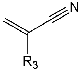 wherein R3 comprises a hydrogen atom, or an alkyl group containing 1 to 6 carbon atoms; and/or the polymeric monomers of the organic polymer further comprise a third monomer, wherein the third monomer has the following constitutional formula:
 wherein R4 comprises a hydrogen atom, or an alkyl group containing 1 to 6 carbon atoms, and R5 comprises a hydrogen atom, or a hydroxy group-substituted alkyl group containing 1 to 6 carbon atoms or alkoxy group containing 1 to 6 carbon atoms; and/orthe polymeric monomers of the organic polymer further comprise a fourth monomer, wherein the fourth monomer has the following constitutional formula:
 wherein R6, R7, R8, and R9 each independently comprises a hydrogen atom, a substituted or unsubstituted phenyl group, a substituted or unsubstituted cycloalkyl group, or a straight-chain or branched-chain alkyl group.
 - The binder according to any one of claims 3 to 6, characterized in that the polymeric monomers of the organic polymer further comprise a second monomer, wherein the second monomer comprises at least one of acrylonitrile, methacrylonitrile, and ethyl acrylonitrile; and/orthe polymeric monomers of the organic polymer further comprise a third monomer, wherein the third monomer comprises at least one of acrylamide, N-methylolacrylamide, and N-butoxymethylacrylamide; and/orthe polymeric monomers of the organic polymer further comprise a fourth monomer, wherein the fourth monomer comprises at least one of ethylene, styrene, butadiene, and isoprene.
- The binder according to any one of claims 3 to 6, characterized in that the polymeric monomers of the organic polymer further comprise a second monomer, wherein the second monomer comprises at least one of acrylonitrile and methacrylonitrile; and/or
the polymeric monomers of the organic polymer further comprise a third monomer, wherein the third monomer comprises at least one of acrylamide and N-methylolacrylamide. - The binder according to any one of claims 3 to 6, characterized in that the polymeric monomers of the organic polymer further comprise a second monomer and a third monomer, wherein the second monomer comprises an organic substance containing an unsaturated nitrile group, the third monomer comprises an organic substance containing an unsaturated amide group, and a weight ratio of the first monomer, the second monomer, and the third monomer is 1:0-0.8:0-0.15.
- The binder according to claim 10, characterized in that the weight ratio of the first monomer, the second monomer, and the third monomer is 1:0.05-0.2:0.05-0.1.
- The binder according to any one of claims 3 to 6, characterized in that the polymeric monomers of the organic polymer further comprise a second monomer, a third monomer, and a fourth monomer, wherein the second monomer comprises an organic substance containing an unsaturated nitrile group, the third monomer comprises an organic substance containing an unsaturated amide group, the fourth monomer comprises an organic substance containing an unsaturated alkenyl group, and a weight ratio of the first monomer, the second monomer, the third monomer, and the fourth monomer is 1:0-0.8:0-0.7:0-0.5.
- The binder according to claim 12, characterized in that the weight ratio of the first monomer, the second monomer, the third monomer, and the fourth monomer is 1:0.05-0.6:0.05-0.3:0-0.2.
- The binder according to claim 1 or 2, characterized in that particle size of the binder satisfies: 3 µm ≤ D50 ≤ 10 µm; and/orparticle size distribution of the binder = (D90 - D10)/D50, wherein the particle size distribution is less than or equal to 2.5; and/orparticle size of the inorganic substance is 0.0001 µm to 2 µm.
- The binder according to claim 1 or 2, characterized in that particle size distribution of the binder = (D90 - D10)/D50, wherein the particle size distribution is less than 2; and/orparticle size of the inorganic substance is 0.01 µm to 0.5 µm; and/orthe inorganic substance comprises at least one of an oxide of silicon, an oxide of aluminum, an oxide of calcium, an oxide of zinc, an oxide of magnesium, sodium sulfate, sodium benzoate, calcium carbonate, and modified materials thereof.
- The binder according to claim 1 or 2, characterized in that particle size distribution of the binder = (D90 - D10)/D50, wherein the particle size distribution is less than 1.8; and/orparticle size of the inorganic substance is 0.01 µm to 0.2 µm; and/orbased on mass of the binder, a mass percentage of the organic polymer is 50% to 99.9%; and/or the inorganic substance comprises at least one of silicon dioxide, aluminum oxide, zinc oxide, magnesium oxide, and sodium benzoate.
- The binder according to claim 1 or 2, characterized in that based on mass of the binder, a mass percentage of the organic polymer is 60% to 99%; and/or
the inorganic substance comprises at least one of fumed silicon dioxide, silicon micro-powder, aluminum oxide, and sodium benzoate. - The binder according to claim 1 or 2, characterized in that based on mass of the binder, a mass percentage of the organic polymer is 70% to 99%; and/or
the inorganic substance comprises silicon dioxide, wherein silicon dioxide particle size in the silicon dioxide is 2 nm to 1 µm. - The binder according to claim 1 or 2, characterized in that an outer surface of the binder is uneven; and/or
the inorganic substance comprises silicon dioxide, wherein silicon dioxide particle size in the silicon dioxide is 5 nm to 100 nm. - The binder according to claim 1 or 2, characterized in that ionic conductivity of the binder is 0.3 mS·cm-1 to 0.6 mS·cm-1; and/or
the inorganic substance comprises silicon dioxide, wherein silicon dioxide particle size in the silicon dioxide is 5 nm to 20 nm. - A separator, characterized by comprising the binder according to any one of claims 1 to 20.
- An electrode plate, characterized by comprising the binder according to any one of claims 1 to 20.
- An electrode assembly, characterized by comprising at least one of the binder according to any one of claims 1 to 20, the separator according to claim 21, and the electrode plate according to claim 22.
- A battery cell, characterized by comprising the electrode assembly according to claim 23.
- A battery, characterized by comprising the battery cell according to claim 24.
- An electric apparatus, characterized by comprising the battery cell according to claim 24 or the battery according to claim 25.
Applications Claiming Priority (2)
| Application Number | Priority Date | Filing Date | Title |
|---|---|---|---|
| CN202310015629 | 2023-01-04 | ||
| PCT/CN2023/098414 WO2024146064A1 (en) | 2023-01-04 | 2023-06-05 | Binder, separator, electrode sheet, electrode assembly, battery cell, battery, and electric device |
Publications (2)
| Publication Number | Publication Date |
|---|---|
| EP4421143A1 true EP4421143A1 (en) | 2024-08-28 |
| EP4421143A4 EP4421143A4 (en) | 2025-03-26 |
Family
ID=89900818
Family Applications (2)
| Application Number | Title | Priority Date | Filing Date |
|---|---|---|---|
| EP23847633.7A Pending EP4421143A4 (en) | 2023-01-04 | 2023-06-05 | Binder, separator, electrode sheet, electrode assembly, battery cell, battery, and electric device |
| EP24738481.1A Pending EP4578912A4 (en) | 2023-01-04 | 2024-01-03 | POLYMER, MANUFACTURING METHOD FOR IT, SEPARATOR, ELECTRODE FILM, BATTERY AND ELECTRICAL DEVICE |
Family Applications After (1)
| Application Number | Title | Priority Date | Filing Date |
|---|---|---|---|
| EP24738481.1A Pending EP4578912A4 (en) | 2023-01-04 | 2024-01-03 | POLYMER, MANUFACTURING METHOD FOR IT, SEPARATOR, ELECTRODE FILM, BATTERY AND ELECTRICAL DEVICE |
Country Status (6)
| Country | Link |
|---|---|
| US (2) | US20240313225A1 (en) |
| EP (2) | EP4421143A4 (en) |
| JP (2) | JP2025511417A (en) |
| KR (2) | KR20240110739A (en) |
| CN (1) | CN118290645A (en) |
| WO (2) | WO2024146064A1 (en) |
Cited By (1)
| Publication number | Priority date | Publication date | Assignee | Title |
|---|---|---|---|---|
| EP4467623A4 (en) * | 2023-04-07 | 2025-07-09 | Contemporary Amperex Technology Hong Kong Ltd | Binder for secondary battery, manufacturing method therefor, separator, battery cell, battery and electrical device |
Family Cites Families (38)
| Publication number | Priority date | Publication date | Assignee | Title |
|---|---|---|---|---|
| DE2261754A1 (en) * | 1972-12-16 | 1974-06-27 | Basf Ag | Translucent coated plastics film for drawing paper - contains hard and fine mineral fillers with large surface area in paper-coating binder, for good marking and erasing qualities |
| KR100491026B1 (en) * | 2003-03-05 | 2005-05-24 | 주식회사 엘지화학 | The cell property, adhesive property and coating property-controlled binder for lithium secondary battery with 2 or more phases |
| WO2006062153A1 (en) * | 2004-12-08 | 2006-06-15 | Hitachi Maxell, Ltd. | Separator for electrochemical device and electrochemical device |
| EP2485302B1 (en) * | 2009-09-30 | 2017-03-08 | Zeon Corporation | Porous membrane for secondary battery, and secondary battery |
| KR20130090437A (en) * | 2012-02-04 | 2013-08-14 | 주식회사 엘지화학 | Binder for secondary battery exhibiting excellent low temperature characteristic |
| KR101708364B1 (en) * | 2012-02-09 | 2017-02-20 | 삼성에스디아이 주식회사 | Composite binder for battery, anode and lithium battery containing the binder |
| US9711785B2 (en) * | 2012-06-07 | 2017-07-18 | Zeon Corporation | Negative electrode slurry composition, lithium ion secondary battery negative electrode, and lithium ion secondary battery |
| US9318743B2 (en) * | 2012-08-01 | 2016-04-19 | Samsung Sdi Co., Ltd. | Binder for electrode of lithium rechargeable battery and electrode for rechargeable battery comprising the same |
| JP6314832B2 (en) * | 2012-11-26 | 2018-04-25 | 日本ゼオン株式会社 | Method for producing electrode / separator laminate and lithium ion secondary battery |
| KR101637889B1 (en) * | 2012-11-29 | 2016-07-08 | 주식회사 엘지화학 | Binder for Secondary Battery Exhibiting Excellent Adhesive Force |
| US9570751B2 (en) * | 2013-02-26 | 2017-02-14 | Samsung Sdi Co., Ltd. | Binder composition for secondary battery, anode including the binder composition, and lithium battery including the anode |
| KR20140106301A (en) * | 2013-02-26 | 2014-09-03 | 삼성에스디아이 주식회사 | Composite binder for secondary battery, anode and lithium battery containing the binder |
| JP2015028842A (en) * | 2013-06-28 | 2015-02-12 | 日本ゼオン株式会社 | Lithium ion secondary battery adhesive, lithium ion secondary battery separator, and lithium ion secondary battery |
| CN103441230B (en) * | 2013-08-21 | 2016-03-09 | 东莞新能源科技有限公司 | Organic/inorganic composite porous isolating membrane and preparation method thereof and electrochemical appliance |
| KR101690515B1 (en) * | 2013-11-21 | 2016-12-29 | 삼성에스디아이 주식회사 | Electrode assembly with improved flexural strength, a method for preparing the same and electro-chemical cell comprising the same |
| JP6378998B2 (en) * | 2014-09-30 | 2018-08-22 | 旭化成株式会社 | Method for manufacturing separator for power storage device |
| KR101811328B1 (en) * | 2015-08-24 | 2017-12-22 | 삼성에스디아이 주식회사 | A separator and an electrochemical battery comprising the separator |
| CN105131875B (en) * | 2015-08-26 | 2017-07-07 | 深圳市贝特瑞新能源材料股份有限公司 | A kind of water adhesive for lithium ion battery, preparation method and its usage |
| JP6759566B2 (en) * | 2015-11-27 | 2020-09-23 | 日本ゼオン株式会社 | Non-aqueous secondary battery |
| CN106519872A (en) * | 2016-12-01 | 2017-03-22 | 深圳市星源材质科技股份有限公司 | Coating slurry, lithium-ion battery separator and preparation methods of coating slurry and lithium-ion battery separator |
| CN106928798B (en) * | 2017-03-23 | 2019-04-12 | 江苏耐斯数码科技股份有限公司 | A kind of low-friction coefficient adhesion-resistant slippery coating and preparation method thereof |
| CN108987751A (en) * | 2017-05-31 | 2018-12-11 | 宁德时代新能源科技股份有限公司 | Binder and secondary battery thereof |
| KR102211109B1 (en) * | 2017-09-15 | 2021-02-02 | 주식회사 엘지화학 | Silicone Electrode Binder |
| CN109796554B (en) * | 2019-01-18 | 2021-04-06 | 广东巴德富新材料有限公司 | Elastic emulsion for zero-titanium system and preparation method thereof |
| US12586868B2 (en) * | 2020-04-06 | 2026-03-24 | Lg Energy Solution, Ltd. | Separator including inorganic porous coating layer including polar binder and acrylic binder with different glass transition temperatures, electrochemical device, and method for manufacturing the same |
| CN115803959B (en) * | 2020-07-20 | 2025-10-24 | 株式会社Lg新能源 | Separator for secondary battery, method for manufacturing the same, method for manufacturing a secondary battery including the separator, and secondary battery manufactured by the method |
| JP7518688B2 (en) * | 2020-07-29 | 2024-07-18 | 松本油脂製薬株式会社 | Secondary battery separator and its use, slurry composition for secondary battery separator, and resin particles for secondary battery separator |
| CN112341961B (en) * | 2020-10-28 | 2023-01-13 | 欣旺达电动汽车电池有限公司 | Adhesive, diaphragm and preparation method thereof |
| JP7451745B2 (en) * | 2020-11-30 | 2024-03-18 | 寧徳時代新能源科技股▲分▼有限公司 | Separators, secondary batteries and devices containing them |
| WO2022120654A1 (en) * | 2020-12-09 | 2022-06-16 | 宁德新能源科技有限公司 | Polymer binder, laminated porous membrane, battery, and electronic apparatus |
| CN112563663B (en) * | 2020-12-11 | 2022-11-11 | 上海恩捷新材料科技有限公司 | Ceramic coating isolation membrane for lithium ion battery |
| KR102928797B1 (en) * | 2020-12-31 | 2026-02-19 | 엘지디스플레이 주식회사 | Adhesive member and display device using the same |
| CN112940650A (en) * | 2021-02-03 | 2021-06-11 | 深圳好电科技有限公司 | Water-based coating for lithium ion battery composite diaphragm, lithium ion battery composite diaphragm and lithium ion battery |
| CN113410576B (en) * | 2021-06-17 | 2023-11-24 | 无锡恩捷新材料科技有限公司 | Battery diaphragm and preparation method thereof, battery and preparation method of core-shell type sphere |
| CN114094274B (en) * | 2021-10-27 | 2024-03-01 | 中材锂膜有限公司 | Battery separation film, preparation method thereof and secondary battery |
| CN117280009A (en) * | 2022-03-25 | 2023-12-22 | 宁德时代新能源科技股份有限公司 | Adhesives and related separators, pole pieces, batteries, battery modules, battery packs and electrical devices |
| CN115260403B (en) * | 2022-08-29 | 2023-12-08 | 深圳市鸿星创新材料有限公司 | Aqueous binder, modified diaphragm, battery and preparation method of aqueous binder |
| CN115466359A (en) * | 2022-10-28 | 2022-12-13 | 深圳新源邦科技有限公司 | Special core-shell emulsion for ceramic coating diaphragm, diaphragm and preparation method of special core-shell emulsion |
-
2023
- 2023-06-05 KR KR1020237039075A patent/KR20240110739A/en not_active Ceased
- 2023-06-05 JP JP2023570171A patent/JP2025511417A/en active Pending
- 2023-06-05 EP EP23847633.7A patent/EP4421143A4/en active Pending
- 2023-06-05 WO PCT/CN2023/098414 patent/WO2024146064A1/en not_active Ceased
- 2023-11-29 CN CN202311633287.7A patent/CN118290645A/en active Pending
-
2024
- 2024-01-03 KR KR1020257010504A patent/KR20250058759A/en active Pending
- 2024-01-03 WO PCT/CN2024/070306 patent/WO2024146548A1/en not_active Ceased
- 2024-01-03 EP EP24738481.1A patent/EP4578912A4/en active Pending
- 2024-01-03 JP JP2025522730A patent/JP2025537498A/en active Pending
- 2024-05-21 US US18/670,605 patent/US20240313225A1/en active Pending
-
2025
- 2025-05-18 US US19/211,224 patent/US20250277100A1/en active Pending
Cited By (1)
| Publication number | Priority date | Publication date | Assignee | Title |
|---|---|---|---|---|
| EP4467623A4 (en) * | 2023-04-07 | 2025-07-09 | Contemporary Amperex Technology Hong Kong Ltd | Binder for secondary battery, manufacturing method therefor, separator, battery cell, battery and electrical device |
Also Published As
| Publication number | Publication date |
|---|---|
| KR20250058759A (en) | 2025-04-30 |
| JP2025511417A (en) | 2025-04-16 |
| KR20240110739A (en) | 2024-07-16 |
| EP4578912A1 (en) | 2025-07-02 |
| JP2025537498A (en) | 2025-11-18 |
| US20240313225A1 (en) | 2024-09-19 |
| CN118290645A (en) | 2024-07-05 |
| EP4421143A4 (en) | 2025-03-26 |
| WO2024146548A1 (en) | 2024-07-11 |
| EP4578912A4 (en) | 2026-04-22 |
| WO2024146064A1 (en) | 2024-07-11 |
| US20250277100A1 (en) | 2025-09-04 |
Similar Documents
| Publication | Publication Date | Title |
|---|---|---|
| EP3678229B1 (en) | Anode active material and anode using same, electrochemical device and electronic device | |
| EP4411857A1 (en) | Negative electrode sheet and manufacturing method therefor, secondary battery, battery module, battery pack, and electrical device | |
| WO2022041259A1 (en) | Secondary battery and preparation method therefor, and battery module, battery pack and device comprising secondary battery | |
| EP4317348A1 (en) | Binder and related separator, electrode sheet, battery, battery module, battery pack and electric device | |
| EP4451452A1 (en) | Separator, secondary battery using same, battery module, battery pack, and electric apparatus | |
| EP3951977A1 (en) | Secondary battery, and battery module, battery pack and device containing same | |
| WO2022133961A1 (en) | Lithium secondary battery, battery module comprising same, battery pack, and electric apparatus | |
| EP4246647A1 (en) | Electrolyte, secondary battery, and electric device | |
| US12297305B2 (en) | Binder composition and separator containing same | |
| EP4379941A1 (en) | Binder and separator membrane comprising same | |
| CN115842118A (en) | Lithium salt composite material, negative plate, preparation method of negative plate, battery and electricity utilization device | |
| EP4693686A1 (en) | Separator and preparation method therefor, battery, and electric device | |
| US20240313225A1 (en) | Binder, separator, electrode plate, electrode assembly, battery cell, battery, and electric apparatus | |
| CN101685860A (en) | Cathode active material, preparation method thereof and cathode and battery containing same | |
| CN101110477B (en) | An electrochemical energy storage and energy conversion device | |
| CN111009687A (en) | Non-aqueous electrolyte and lithium ion battery | |
| EP4654282A1 (en) | Negative electrode sheet and preparation method therefor, battery cell, battery and electric device | |
| WO2023050832A1 (en) | Lithium ion battery, battery module, battery pack, and electrical device | |
| CN115810707A (en) | Negative pole piece, secondary battery, battery module, battery pack and electric device | |
| CN119108634B (en) | Electrochemical device and electronic device | |
| CN119833752B (en) | Battery and preparation method thereof, and electrical equipment | |
| EP4624545A1 (en) | Polymer, separator film, electrode sheet, battery, and electrical apparatus | |
| CN119447207B (en) | Battery cells and their manufacturing methods, and soft-pack lithium-ion batteries and their applications | |
| EP4641729A1 (en) | Lithium ion battery and electric apparatus | |
| EP4629425A1 (en) | Separator and preparation method therefor, lithium ion battery, and electric device |
Legal Events
| Date | Code | Title | Description |
|---|---|---|---|
| STAA | Information on the status of an ep patent application or granted ep patent |
Free format text: STATUS: UNKNOWN |
|
| STAA | Information on the status of an ep patent application or granted ep patent |
Free format text: STATUS: THE INTERNATIONAL PUBLICATION HAS BEEN MADE |
|
| PUAI | Public reference made under article 153(3) epc to a published international application that has entered the european phase |
Free format text: ORIGINAL CODE: 0009012 |
|
| STAA | Information on the status of an ep patent application or granted ep patent |
Free format text: STATUS: REQUEST FOR EXAMINATION WAS MADE |
|
| 17P | Request for examination filed |
Effective date: 20240205 |
|
| AK | Designated contracting states |
Kind code of ref document: A1 Designated state(s): AL AT BE BG CH CY CZ DE DK EE ES FI FR GB GR HR HU IE IS IT LI LT LU LV MC ME MK MT NL NO PL PT RO RS SE SI SK SM TR |
|
| RAP1 | Party data changed (applicant data changed or rights of an application transferred) |
Owner name: CONTEMPORARY AMPEREX TECHNOLOGY(HONG KONG) LIMITED |
|
| REG | Reference to a national code |
Ref country code: DE Ref legal event code: R079 Free format text: PREVIOUS MAIN CLASS: C09J0133140000 Ipc: C08F0220180000 |
|
| A4 | Supplementary search report drawn up and despatched |
Effective date: 20250225 |
|
| RIC1 | Information provided on ipc code assigned before grant |
Ipc: H01M 50/446 20210101ALI20250219BHEP Ipc: H01M 50/434 20210101ALI20250219BHEP Ipc: H01M 4/62 20060101ALI20250219BHEP Ipc: H01M 50/414 20210101ALI20250219BHEP Ipc: H01M 10/0525 20100101ALI20250219BHEP Ipc: C08J 3/12 20060101ALI20250219BHEP Ipc: C08F 220/20 20060101ALI20250219BHEP Ipc: C08F 220/18 20060101AFI20250219BHEP |
|
| DAV | Request for validation of the european patent (deleted) | ||
| DAX | Request for extension of the european patent (deleted) |