EP4420999A1 - Wiper blade packaging - Google Patents
Wiper blade packaging Download PDFInfo
- Publication number
- EP4420999A1 EP4420999A1 EP24158133.9A EP24158133A EP4420999A1 EP 4420999 A1 EP4420999 A1 EP 4420999A1 EP 24158133 A EP24158133 A EP 24158133A EP 4420999 A1 EP4420999 A1 EP 4420999A1
- Authority
- EP
- European Patent Office
- Prior art keywords
- packaging
- connector
- arm
- wiper
- identification feature
- Prior art date
- Legal status (The legal status is an assumption and is not a legal conclusion. Google has not performed a legal analysis and makes no representation as to the accuracy of the status listed.)
- Granted
Links
Images




Classifications
-
- B—PERFORMING OPERATIONS; TRANSPORTING
- B65—CONVEYING; PACKING; STORING; HANDLING THIN OR FILAMENTARY MATERIAL
- B65D—CONTAINERS FOR STORAGE OR TRANSPORT OF ARTICLES OR MATERIALS, e.g. BAGS, BARRELS, BOTTLES, BOXES, CANS, CARTONS, CRATES, DRUMS, JARS, TANKS, HOPPERS, FORWARDING CONTAINERS; ACCESSORIES, CLOSURES, OR FITTINGS THEREFOR; PACKAGING ELEMENTS; PACKAGES
- B65D85/00—Containers, packaging elements or packages, specially adapted for particular articles or materials
- B65D85/68—Containers, packaging elements or packages, specially adapted for particular articles or materials for machines, engines or vehicles in assembled or dismantled form
-
- B—PERFORMING OPERATIONS; TRANSPORTING
- B65—CONVEYING; PACKING; STORING; HANDLING THIN OR FILAMENTARY MATERIAL
- B65D—CONTAINERS FOR STORAGE OR TRANSPORT OF ARTICLES OR MATERIALS, e.g. BAGS, BARRELS, BOTTLES, BOXES, CANS, CARTONS, CRATES, DRUMS, JARS, TANKS, HOPPERS, FORWARDING CONTAINERS; ACCESSORIES, CLOSURES, OR FITTINGS THEREFOR; PACKAGING ELEMENTS; PACKAGES
- B65D77/00—Packages formed by enclosing articles or materials in preformed containers, e.g. boxes, cartons, sacks or bags
- B65D77/04—Articles or materials enclosed in two or more containers disposed one within another
- B65D77/0446—Articles or materials enclosed in two or more containers disposed one within another the inner and outer containers being rigid or semi-rigid and the outer container being of polygonal cross-section not formed by folding or erecting one or more blanks
- B65D77/0453—Articles or materials enclosed in two or more containers disposed one within another the inner and outer containers being rigid or semi-rigid and the outer container being of polygonal cross-section not formed by folding or erecting one or more blanks the inner container having a polygonal cross-section
-
- B—PERFORMING OPERATIONS; TRANSPORTING
- B65—CONVEYING; PACKING; STORING; HANDLING THIN OR FILAMENTARY MATERIAL
- B65D—CONTAINERS FOR STORAGE OR TRANSPORT OF ARTICLES OR MATERIALS, e.g. BAGS, BARRELS, BOTTLES, BOXES, CANS, CARTONS, CRATES, DRUMS, JARS, TANKS, HOPPERS, FORWARDING CONTAINERS; ACCESSORIES, CLOSURES, OR FITTINGS THEREFOR; PACKAGING ELEMENTS; PACKAGES
- B65D25/00—Details of other kinds or types of rigid or semi-rigid containers
- B65D25/20—External fittings
-
- B—PERFORMING OPERATIONS; TRANSPORTING
- B65—CONVEYING; PACKING; STORING; HANDLING THIN OR FILAMENTARY MATERIAL
- B65D—CONTAINERS FOR STORAGE OR TRANSPORT OF ARTICLES OR MATERIALS, e.g. BAGS, BARRELS, BOTTLES, BOXES, CANS, CARTONS, CRATES, DRUMS, JARS, TANKS, HOPPERS, FORWARDING CONTAINERS; ACCESSORIES, CLOSURES, OR FITTINGS THEREFOR; PACKAGING ELEMENTS; PACKAGES
- B65D2585/00—Containers, packaging elements or packages specially adapted for particular articles or materials
- B65D2585/68—Containers, packaging elements or packages specially adapted for particular articles or materials for machines, engines, or vehicles in assembled or dismantled form
- B65D2585/6802—Containers, packaging elements or packages specially adapted for particular articles or materials for machines, engines, or vehicles in assembled or dismantled form specific machines, engines or vehicles
- B65D2585/6875—Containers, packaging elements or packages specially adapted for particular articles or materials for machines, engines, or vehicles in assembled or dismantled form specific machines, engines or vehicles engines, motors, machines and vehicle parts
- B65D2585/6882—Containers, packaging elements or packages specially adapted for particular articles or materials for machines, engines, or vehicles in assembled or dismantled form specific machines, engines or vehicles engines, motors, machines and vehicle parts vehicle parts
- B65D2585/6885—Containers, packaging elements or packages specially adapted for particular articles or materials for machines, engines, or vehicles in assembled or dismantled form specific machines, engines or vehicles engines, motors, machines and vehicle parts vehicle parts wiper blades
Definitions
- One technique for identifying which type of connector is used on a given wiper arm involves traditional coinage. That is, a consumer would be instructed to use a coin having a known diameter to identify the connector size. For example, a U.S. one-cent piece, which has a diameter of 19.05 mm, will fit into the end of the wide (22mm) arm, but will not fit into the end of the narrow (19mm) arm. In a modern, generally cashless society, however, most consumers don't carry change.
- the connectors and instructions can be strewn in different directions causing a delay in both finding the connectors and instructions and understanding the operation of the connectors from the instructions. Since there is not a convenient place to store the connectors and instructions once taken out of their package, the connectors and instructions can be easily lost or damaged.
- the present disclosure relates generally to improved wiper blade packaging, substantially as illustrated by and described in connection with at least one of the figures, as set forth more completely in the claims. More specifically, the present disclosure relates to wiper blade packaging that enables a consumer to easily ascertain from the packaging whether the connector is appropriate for a given wiper arm.
- first,” “second,” “top,” “bottom,” “side,” “front,” “back,” and the like are words of convenience and are not to be construed as limiting terms.
- first side is located adjacent or near a second side
- second side do not imply any specific order in which the sides are ordered.
- x and/or y means any element of the three-element set ⁇ (x), (y), (x, y) ⁇ . In other words, “x and/or y” means “one or both of x and y”.
- x, y, and/or z means any element of the seven-element set ⁇ (x), (y), (z), (x, y), (x, z), (y, z), (x, y, z) ⁇ . In other words, "x, y, and/or z” means “one or more of x, y, and z.”
- Wiper arms used in vehicles vary in size and shape. In some cases, wiper arms can be the same shape, but will still vary in size. These wiper arms are often differentiated in marketing material by a size-related adjective describing the arm (e.g., small J-Hook, large J-Hook, etc.). Currently, the consumer must have a ruler, a penny, or the ability to visualize measurements to differentiate the arm size from the other similarly shaped arms. While wiper arms are most often associated with automobiles (e.g., cars, trucks, etc.), they are likewise employed in numerous other vehicles, such as trains, watercraft, and aircraft. Therefore, the following disclosure should not be limited to wiper blades and wiper arms used in automobiles, but rather would be applicable to wiper blades and wiper arms used in any type of vehicle.
- packaging for a wiper blade having a blade-side connector configured to engage a wiper arm comprises: an inner component configured to house the wiper blade; and an outer sleeve component having an enclosure that defines a cavity configured to receive at least a portion of the inner component. At least one of the inner component and the outer sleeve component comprises a connector-identification feature configured to indicate a compatible arm-side connector of the wiper arm.
- packaging for a wiper blade having a blade-side connector configured to engage a wiper arm comprises: a backing panel; and an enclosure coupled to the backing panel and configured to house the wiper blade.
- the backing panel having a connector-identification feature configured to indicate a compatible arm-side connector of the wiper arm.
- the backing panel and the enclosure can be adhered to one another to form one-piece packaging.
- the connector-identification feature can be a pre-punched cutout or a perforated cutout that is sized and shaped to correspond to a size and a shape of the compatible arm-side connector.
- the connector-identification feature is a circular cutout that is sized to correspond to a size of the compatible arm-side connector.
- the circular cutout can have a diameter of about 19mm.
- the outer sleeve component which can be fabricated from cardboard or plastic, comprises the connector-identification feature.
- the inner component is fabricated from a transparent plastic material.
- packaging for a wiper blade having a blade-side connector configured to engage a wiper arm comprises: an inner component configured to house the wiper blade; and an outer sleeve component that defines a cavity configured to receive at least a portion of the inner component.
- the outer sleeve component comprises a connector-identification feature can be configured to indicate a compatible arm-side connector of the wiper arm.
- the connector-identification feature can be is sized and shaped to correspond to a size and a shape of the compatible arm-side connector, such as a J-shaped cutout.
- FIG 1a illustrates an example vehicle 100 having a windshield 102 and a pair of wiper blades 104.
- each wiper blade 104 is removably coupled to with a wiper arm 106 of the vehicle 100 via a coupling 108.
- the wiper arms 106 (and, therefore, the wiper blades 104) are configured to translate back and forth across the windshield 102 to clear the windshield 102 of rain, snow, and debris via one or more electric motors and mechanical linkages associated with the vehicle 100.
- FIG. 1b illustrates an assembly view of an example coupling 108 between the wiper blade 104 and the wiper arm 106.
- each wiper arm 106 includes or otherwise defines, at its distal end, an arm-side connector 110.
- the arm-side connector 110 is configured to engage and secure the wiper blade 104 via a complimentary blade-side connector 112 positioned on or otherwise associated with the wiper blade 104.
- the arm-side connector 110 is inserted into a J-shaped slot 114 of the blade-side connector 112 as indicated by arrow 116.
- a locking cap 118 can be folded as indicated by arrow 120 (e.g., pivoted about a hinge) and positioned to cover, secure, and protect the connected arm-side connector 110 and blade-side connector 112.
- the wiper arm 106 includes an arm-side connector 110 configured a J-Hook connector 122, but other connector types are contemplated.
- Figures 1c through 1f illustrate other suitable example connector types for a coupling 108.
- Figure 1c illustrates a large J-Hook connector 110a
- Figure 1d illustrates a small J-Hook connector 110b.
- the large J-Hook connector 110a and the small J-Hook connector 110b are substantially the same as one another (and the J-Hook connector 122 of Figure 1b ), except for the size.
- Figure 1e illustrates a large wiper pin connector 110c
- Figure 1f illustrates a small wiper pin connector 110d.
- the large wiper pin connector 110c and the small wiper pin connector 110d are likewise substantially the same other than size (e.g., length and diameter). A difference, however, is that a pin 124 of the large wiper pin connector 110c and/or the small wiper pin connector 110d would be inserted into a corresponding hole or opening on the blade-side connector 112 (rather than a J-shaped slot 114 as illustrated in Figure 1b ).
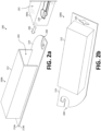
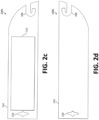
- Figures 2a through 2h illustrate example packaging 200 for one or more wiper blades 104.
- Figure 2a illustrates a perspective assembly view of the packaging 200
- Figure 2b illustrates a perspective assembled view of the packaging 200
- Figures 2c and 2d illustrate, respectively, front and rear plan views of the packaging 200
- Figures 2e through 2h illustrate right, left, top, and bottom elevation views of the packaging 200.
- the packaging 200 allows for the contents of the packaging 200 to be displayed in an aesthetically pleasing manner, while also enabling the consumer to easily identify and verify the type of connector needed without having to open the packaging 200.
- wiper blades 104 are sold individually and are illustrated as such, but it is contemplated that the packaging 200 described herein can be sized to accommodate two or more wiper blades 104.
- the packaging 200 includes an inner component 200a and an outer sleeve component 200b.
- the inner component 200a and the outer sleeve component 200b are fabricated from one or more resilient materials, such as cardboard, plastic, metal, or a combination thereof.
- the inner component 200a defines an enclosure 202 configured to house the one or more wiper blades 104.
- the inner component 200a may be fabricated from a transparent plastic material that enables the consumer to view the one or more wiper blades 104 contained therein.
- the inner component 200a is configured to insert into a cavity 204 defined by the outer sleeve component 200b as indicated by arrow 206.
- the illustrated outer sleeve component 200b generally comprises a backing panel 214 (or similar structure) with an enclosure 212 (or pocket) configured to receive at least a portion of the inner component 200a.
- the backing panel 214 comprises a first surface 214a and a second surface 214b, where the enclosure 212 extends outwardly from the first surface 214a.
- the outer sleeve component 200b retains the inner component 200a via one or more of an adhesive, tape, friction, protrusions, or otherwise.
- the outer sleeve component 200b can be a cardboard or plastic sleeve that is printed with or otherwise provides various information or indicia pertaining to the enclosed one or more wiper blades 104 (and usage thereof).
- the enclosure 212 is adhered to the backing panel 214, but in other examples, can also be a unitary structure.
- the enclosure 212 and the backing panel 214 can be fabricated from the same resilient material, but is not required.
- the enclosure 212 could be fabricated from a plastic material that is adhered to a backing panel 214, which could be fabricated from cardboard.
- a benefit of the packaging 200 described herein is the ability to identify a type of arm-side connector 110 without requiring an outside tool for identification or that the consumer open the packaging 200.
- the outer sleeve component 200b defines one or more connector-identification features 208 (e.g., cutouts, openings, slits, slots, outlines, or otherwise) that a customer can use to identify which type of arm-side connector 110 is used on the vehicle 100.
- the one or more connector-identification features 208 are formed in or on the outer sleeve component 200b and generally corresponds to the size and/or shape of the applicable arm-side connector 110.
- the connector-identification feature 208 can be a pre-punched or perforated cutout that is sized and shaped to correspond to a size and a shape of the compatible arm-side connector 110.
- the one or more connector-identification features 208 can be used to determine whether the blade-side connector 112 employs or is compatible with, for example, a large J-Hook connector 110a, a small J-Hook connector 110b, a large wiper pin connector 110c, a small wiper pin connector 110d, etc.
- the example connector-identification feature 208 illustrated in Figures 2a through 2h is J-shaped to correspond to a J-Hook connector 122. To that end, rather than opening the packaging 200 and without needing to measure the wiper arm 106 or the arm-side connector 110 (e.g., with a penny, a ruler, or otherwise), consumers can identify the type of arm-side connector 110 using the one or more connector-identification features 208 formed in or on the packaging 200.
- the connector-identification features 208 can be either a pre-punched cutout or a perforated cutout where the consumer can punch out the material at the time of use to reveal the cutout. Pre-punching the connector-identification feature 208 reduces the amount of effort needed from the consumer, but using a perforated connector-identification feature 208 offers some advantages. For example, perforating the connector-identification features 208 can mitigate damaged to the shape of the cutout prior to use (e.g., during transit or on the shelf). In practice, the consumer could pass the arm-side connector 110 through the cutout of the connector-identification features 208 to confirm size and shape.
- the outer sleeve component 200b further comprises a hang tab 210 to enable the retailer to hang the packaging 200 on a hook (e.g., in a retail setting).
- the hang tab 210 can be punched through the outer sleeve component 200b via a hang tab hole-punch.
- the hang tab 210 can be provide via a separate handle (or tag) that is attached to outer sleeve component 200b to serve for hanging the packaging 200 on the hook.
- Figures 2a through 2h illustrate a pre-punched connector-identification features 208 that correspond to a J-Hook connector
- Figures 3a through 3d illustrate a pre-punched connector-identification features 208 that correspond to a J-Hook connector
- Figure 3a illustrates a circular connector-identification feature 302.
- a coin having a known diameter (e.g., a U.S. one-cent piece).
- a circular connector-identification feature 302 can be provided as a circular cutout having a known diameter (e.g., ⁇ 19mm) that can be punched out of the packaging 200 and used as a coin substitute. The circular connector-identification feature 302 can then be used to determine which size J-Hook connector is provided.
- Figure 3b illustrates a connector-identification feature 304 embodied as a quadrilateral cutout at the top of the packaging 200 to allow a consumer to identify pinch tab button (PTB) and pin and hold (P&H) type.
- PTB pinch tab button
- P&H pin and hold
- the consumer can slide the arm-side connector 110 into the packaging connector-identification feature 304 to verify their arm type.
- Figure 3c illustrates a connector-identification feature 306 that is an outline printed on a surface of the packaging 200.
- the connector-identification feature 306 may be provided as a printed outline where the consumer aligns the outline to the arm-side connector 110 with the connector-identification features 208.
- the circular connector-identification feature 302 can be provided via a separate card 308 that is provided with the packaging 200.
- Figure 3d illustrates an example separate card 308 that contains the circular connector-identification feature 302. In the illustrated example, the separate card 308 is square, but other shapes are contemplated. Further, while a circular connector-identification feature 302 is illustrated, a J-shaped cutout could instead be provided via the separate card 308.
- Figures 2a through 2h illustrate a two-piece packaging 200 having an inner component 200a and an outer sleeve component 200b
- the various connector-identification features describe herein should not be construed as limited to configurations for the packaging 200 that use such a two-piece configuration.
- the packaging may be a one-piece component formed via one or more components that are coupled to one another or integrally formed.
- FIG. 4 illustrates example one-piece packaging 400 in accordance with an aspect of the present disclosure.
- the one-piece packaging 400 comprises a backing panel 402 with a transparent enclosure 404 adhered or otherwise attached thereto.
- the transparent enclosure 404 can be fabricated via, for example, a thermoforming technique and adhered to the backing panel 402 via an adhesive, staples, or the like.
- the backing panel 402 is removed (e.g., pulled or ripped away).
- one or more of the described connector-identification features e.g., connector-identification features 208, circular connector-identification feature 302, connector-identification feature 304, etc.
- the described connector-identification features can be formed in or on the backing panel 402.
- one-piece packaging may be provided as a clam shell package (akin to a blister pack) or equivalent thereof.
- a PVC clam shell package can be shaped to receive and house the wiper blade 104 and then sealed (e.g., via adhesive, a welding technique, or otherwise) to hold the wiper blade 104 in place.
- a flat portion of the clam shell package can be punched or otherwise formed to provide the described connector-identification features.
- an insert formed from a resilient material can be included within the PVC clam shell package to provide one or more of the above-described connector-identification features.
Landscapes
- Engineering & Computer Science (AREA)
- Mechanical Engineering (AREA)
- Packaging Of Annular Or Rod-Shaped Articles, Wearing Apparel, Cassettes, Or The Like (AREA)
- Packages (AREA)
Abstract
Description
- The present application claims priority to
United States Provisional Patent Application No. 63/447,431, filed February 22, 2023 - Vehicle use a variety of wiper arms to move a wiper blade. Since wiper blades need to be replaced periodically, a consumer is often faced with the difficulty of matching the wiper arm of the consumer's vehicle with a compatible replacement wiper blade.
- One technique for identifying which type of connector is used on a given wiper arm involves traditional coinage. That is, a consumer would be instructed to use a coin having a known diameter to identify the connector size. For example, a U.S. one-cent piece, which has a diameter of 19.05 mm, will fit into the end of the wide (22mm) arm, but will not fit into the end of the narrow (19mm) arm. In a modern, generally cashless society, however, most consumers don't carry change.
- This situation can be addressed by supplying multiple connectors in either separate packages or with the wiper blade itself so that the consumer could match the appropriate connector with the wiper arm of the consumer's vehicle. This, however, results in wasted materials and expense. Further, it is often hard for the consumer to easily ascertain from the packaging of the connectors whether the connectors are appropriate for the wiper arm or whether their attachment will be difficult accomplish. In addition, the packaging of connectors often is neither aesthetically pleasing nor educational in nature and so the selling of the connectors by a vendor to a consumer can be difficult.
- Furthermore, when opening up the contents of the packages, the connectors and instructions can be strewn in different directions causing a delay in both finding the connectors and instructions and understanding the operation of the connectors from the instructions. Since there is not a convenient place to store the connectors and instructions once taken out of their package, the connectors and instructions can be easily lost or damaged.
- Therefore, a need exists for wiper blade packaging that enables a consumer to easily and reliably ascertain from the packaging whether the connector is compatible or otherwise appropriate for a given wiper arm of a vehicle.
- The present disclosure relates generally to improved wiper blade packaging, substantially as illustrated by and described in connection with at least one of the figures, as set forth more completely in the claims. More specifically, the present disclosure relates to wiper blade packaging that enables a consumer to easily ascertain from the packaging whether the connector is appropriate for a given wiper arm.
- The foregoing and other objects, features, and advantages of the devices, systems, and methods described herein will be apparent from the following description of particular examples thereof, as illustrated in the accompanying figures; where like or similar reference numbers refer to like or similar structures. The figures are not necessarily to scale, emphasis instead being placed upon illustrating the principles of the devices, systems, and methods described herein.
-
Figure 1a illustrates an example vehicle having a windshield and a pair of wiper blades. -
Figure 1b illustrates an assembly view of an example connection point between the wiper blade and the wiper arm. -
Figures 1c and 1d illustrate, respectively, example large and small J-Hook connectors. -
Figures 1e and 1f illustrate, respectively, example large and small wiper pin connector. -
Figure 2a illustrates a perspective assembly view of packaging in accordance with an aspect of the present disclosure. -
Figure 2b illustrates a perspective assembled view of the packaging ofFigure 2a . -
Figures 2c and 2d illustrate, respectively, front and rear plan views of the packaging ofFigure 2a . -
Figures 2e through 2h illustrate right, left, top, and bottom elevation views of the packaging ofFigure 2a . -
Figure 3a illustrates a circular connector-identification feature in accordance with another aspect of the present disclosure. -
Figure 3b illustrates a connector-identification feature embodied as a quadrilateral cutout in accordance with yet another aspect of the present disclosure. -
Figure 3c illustrates a connector-identification feature that is an outline printed on a surface of the packaging in accordance with yet another aspect of the present disclosure. -
Figure 3d illustrates an example separate card that defines a circular connector-identification feature in accordance with yet another aspect of the present disclosure. -
Figure 4 illustrates example one-piece packaging in accordance with yet another aspect of the present disclosure. - References to items in the singular should be understood to include items in the plural, and vice versa, unless explicitly stated otherwise or clear from the text. Grammatical conjunctions are intended to express any and all disjunctive and conjunctive combinations of conjoined clauses, sentences, words, and the like, unless otherwise stated or clear from the context. Recitation of ranges of values herein are not intended to be limiting, referring instead individually to any and all values falling within and/or including the range, unless otherwise indicated herein, and each separate value within such a range is incorporated into the specification as if it were individually recited herein. In the following description, it is understood that terms such as "first," "second," "top," "bottom," "side," "front," "back," and the like are words of convenience and are not to be construed as limiting terms. For example, while in some examples a first side is located adjacent or near a second side, the terms "first side" and "second side" do not imply any specific order in which the sides are ordered.
- The terms "about," "approximately," "substantially," or the like, when accompanying a numerical value, are to be construed as indicating a deviation as would be appreciated by one of ordinary skill in the art to operate satisfactorily for an intended purpose. Ranges of values and/or numeric values are provided herein as examples only, and do not constitute a limitation on the scope of the disclosure. The use of any and all examples, or exemplary language ("e.g.," "such as," or the like) provided herein, is intended merely to better illuminate the disclosed examples and does not pose a limitation on the scope of the disclosure. The terms "e.g.," and "for example" set off lists of one or more non-limiting examples, instances, or illustrations. No language in the specification should be construed as indicating any unclaimed element as essential to the practice of the disclosed examples.
- The term "and/or" means any one or more of the items in the list joined by "and/or." As an example, "x and/or y" means any element of the three-element set {(x), (y), (x, y)}. In other words, "x and/or y" means "one or both of x and y". As another example, "x, y, and/or z" means any element of the seven-element set {(x), (y), (z), (x, y), (x, z), (y, z), (x, y, z)}. In other words, "x, y, and/or z" means "one or more of x, y, and z."
- Wiper arms used in vehicles vary in size and shape. In some cases, wiper arms can be the same shape, but will still vary in size. These wiper arms are often differentiated in marketing material by a size-related adjective describing the arm (e.g., small J-Hook, large J-Hook, etc.). Currently, the consumer must have a ruler, a penny, or the ability to visualize measurements to differentiate the arm size from the other similarly shaped arms. While wiper arms are most often associated with automobiles (e.g., cars, trucks, etc.), they are likewise employed in numerous other vehicles, such as trains, watercraft, and aircraft. Therefore, the following disclosure should not be limited to wiper blades and wiper arms used in automobiles, but rather would be applicable to wiper blades and wiper arms used in any type of vehicle.
- In one example, packaging for a wiper blade having a blade-side connector configured to engage a wiper arm comprises: an inner component configured to house the wiper blade; and an outer sleeve component having an enclosure that defines a cavity configured to receive at least a portion of the inner component. At least one of the inner component and the outer sleeve component comprises a connector-identification feature configured to indicate a compatible arm-side connector of the wiper arm.
- In another example, packaging for a wiper blade having a blade-side connector configured to engage a wiper arm comprises: a backing panel; and an enclosure coupled to the backing panel and configured to house the wiper blade. The backing panel having a connector-identification feature configured to indicate a compatible arm-side connector of the wiper arm. The backing panel and the enclosure can be adhered to one another to form one-piece packaging.
- The connector-identification feature can be a pre-punched cutout or a perforated cutout that is sized and shaped to correspond to a size and a shape of the compatible arm-side connector. In another example, the connector-identification feature is a circular cutout that is sized to correspond to a size of the compatible arm-side connector. For example, the circular cutout can have a diameter of about 19mm. In some examples, the outer sleeve component, which can be fabricated from cardboard or plastic, comprises the connector-identification feature. The inner component is fabricated from a transparent plastic material.
- In another example, packaging for a wiper blade having a blade-side connector configured to engage a wiper arm comprises: an inner component configured to house the wiper blade; and an outer sleeve component that defines a cavity configured to receive at least a portion of the inner component. The outer sleeve component comprises a connector-identification feature can be configured to indicate a compatible arm-side connector of the wiper arm. The connector-identification feature can be is sized and shaped to correspond to a size and a shape of the compatible arm-side connector, such as a J-shaped cutout.
-
Figure 1a illustrates anexample vehicle 100 having awindshield 102 and a pair ofwiper blades 104. As illustrated, eachwiper blade 104 is removably coupled to with awiper arm 106 of thevehicle 100 via acoupling 108. As is known in the art, the wiper arms 106 (and, therefore, the wiper blades 104) are configured to translate back and forth across thewindshield 102 to clear thewindshield 102 of rain, snow, and debris via one or more electric motors and mechanical linkages associated with thevehicle 100. -
Figure 1b illustrates an assembly view of anexample coupling 108 between thewiper blade 104 and thewiper arm 106. As illustrated, eachwiper arm 106 includes or otherwise defines, at its distal end, an arm-side connector 110. The arm-side connector 110 is configured to engage and secure thewiper blade 104 via a complimentary blade-side connector 112 positioned on or otherwise associated with thewiper blade 104. In the illustrated example, the arm-side connector 110 is inserted into a J-shapedslot 114 of the blade-side connector 112 as indicated byarrow 116. Once assembled, alocking cap 118 can be folded as indicated by arrow 120 (e.g., pivoted about a hinge) and positioned to cover, secure, and protect the connected arm-side connector 110 and blade-side connector 112. - In the illustrated example, the
wiper arm 106 includes an arm-side connector 110 configured a J-Hook connector 122, but other connector types are contemplated. For example,Figures 1c through 1f illustrate other suitable example connector types for acoupling 108. Specifically,Figure 1c illustrates a large J-Hook connector 110a, whileFigure 1d illustrates a small J-Hook connector 110b. The large J-Hook connector 110a and the small J-Hook connector 110b are substantially the same as one another (and the J-Hook connector 122 ofFigure 1b ), except for the size.Figure 1e illustrates a largewiper pin connector 110c, whileFigure 1f illustrates a smallwiper pin connector 110d. The largewiper pin connector 110c and the smallwiper pin connector 110d are likewise substantially the same other than size (e.g., length and diameter). A difference, however, is that apin 124 of the largewiper pin connector 110c and/or the smallwiper pin connector 110d would be inserted into a corresponding hole or opening on the blade-side connector 112 (rather than a J-shapedslot 114 as illustrated inFigure 1b ). -
Figures 2a through 2h illustrateexample packaging 200 for one ormore wiper blades 104. Specifically,Figure 2a illustrates a perspective assembly view of thepackaging 200, whileFigure 2b illustrates a perspective assembled view of thepackaging 200.Figures 2c and 2d illustrate, respectively, front and rear plan views of thepackaging 200, whileFigures 2e through 2h illustrate right, left, top, and bottom elevation views of thepackaging 200. As will be apparent from the subject disclosure, thepackaging 200 allows for the contents of thepackaging 200 to be displayed in an aesthetically pleasing manner, while also enabling the consumer to easily identify and verify the type of connector needed without having to open thepackaging 200. Traditionally,wiper blades 104 are sold individually and are illustrated as such, but it is contemplated that thepackaging 200 described herein can be sized to accommodate two ormore wiper blades 104. - In the illustrated example, the
packaging 200 includes aninner component 200a and anouter sleeve component 200b. Theinner component 200a and theouter sleeve component 200b are fabricated from one or more resilient materials, such as cardboard, plastic, metal, or a combination thereof. Theinner component 200a defines anenclosure 202 configured to house the one ormore wiper blades 104. In one example, as illustrated, theinner component 200a may be fabricated from a transparent plastic material that enables the consumer to view the one ormore wiper blades 104 contained therein. - As best illustrated in
Figure 2a , theinner component 200a is configured to insert into acavity 204 defined by theouter sleeve component 200b as indicated byarrow 206. To that end, the illustratedouter sleeve component 200b generally comprises a backing panel 214 (or similar structure) with an enclosure 212 (or pocket) configured to receive at least a portion of theinner component 200a. In the illustrated example, thebacking panel 214 comprises afirst surface 214a and asecond surface 214b, where theenclosure 212 extends outwardly from thefirst surface 214a. - The
outer sleeve component 200b retains theinner component 200a via one or more of an adhesive, tape, friction, protrusions, or otherwise. In one example, theouter sleeve component 200b can be a cardboard or plastic sleeve that is printed with or otherwise provides various information or indicia pertaining to the enclosed one or more wiper blades 104 (and usage thereof). In some examples, theenclosure 212 is adhered to thebacking panel 214, but in other examples, can also be a unitary structure. Theenclosure 212 and thebacking panel 214 can be fabricated from the same resilient material, but is not required. For example, theenclosure 212 could be fabricated from a plastic material that is adhered to abacking panel 214, which could be fabricated from cardboard. - A benefit of the
packaging 200 described herein is the ability to identify a type of arm-side connector 110 without requiring an outside tool for identification or that the consumer open thepackaging 200. To that end, theouter sleeve component 200b defines one or more connector-identification features 208 (e.g., cutouts, openings, slits, slots, outlines, or otherwise) that a customer can use to identify which type of arm-side connector 110 is used on thevehicle 100. In the illustrated example, the one or more connector-identification features 208 are formed in or on theouter sleeve component 200b and generally corresponds to the size and/or shape of the applicable arm-side connector 110. For example, the connector-identification feature 208 can be a pre-punched or perforated cutout that is sized and shaped to correspond to a size and a shape of the compatible arm-side connector 110. - The one or more connector-identification features 208 can be used to determine whether the blade-
side connector 112 employs or is compatible with, for example, a large J-Hook connector 110a, a small J-Hook connector 110b, a largewiper pin connector 110c, a smallwiper pin connector 110d, etc. The example connector-identification feature 208 illustrated inFigures 2a through 2h is J-shaped to correspond to a J-Hook connector 122. To that end, rather than opening thepackaging 200 and without needing to measure thewiper arm 106 or the arm-side connector 110 (e.g., with a penny, a ruler, or otherwise), consumers can identify the type of arm-side connector 110 using the one or more connector-identification features 208 formed in or on thepackaging 200. - The connector-identification features 208 can be either a pre-punched cutout or a perforated cutout where the consumer can punch out the material at the time of use to reveal the cutout. Pre-punching the connector-
identification feature 208 reduces the amount of effort needed from the consumer, but using a perforated connector-identification feature 208 offers some advantages. For example, perforating the connector-identification features 208 can mitigate damaged to the shape of the cutout prior to use (e.g., during transit or on the shelf). In practice, the consumer could pass the arm-side connector 110 through the cutout of the connector-identification features 208 to confirm size and shape. - The
outer sleeve component 200b further comprises ahang tab 210 to enable the retailer to hang thepackaging 200 on a hook (e.g., in a retail setting). In one example, as illustrated, thehang tab 210 can be punched through theouter sleeve component 200b via a hang tab hole-punch. In another example, thehang tab 210 can be provide via a separate handle (or tag) that is attached toouter sleeve component 200b to serve for hanging thepackaging 200 on the hook. - While
Figures 2a through 2h illustrate a pre-punched connector-identification features 208 that correspond to a J-Hook connector, other shapes and configurations are contemplated, including those examples illustrated inFigures 3a through 3d . -
Figure 3a illustrates a circular connector-identification feature 302. As noted above, one technique for identifying which type of connector is used on the wiper arm involves a coin having a known diameter (e.g., a U.S. one-cent piece). To obviate the need for coin, a circular connector-identification feature 302 can be provided as a circular cutout having a known diameter (e.g., ~19mm) that can be punched out of thepackaging 200 and used as a coin substitute. The circular connector-identification feature 302 can then be used to determine which size J-Hook connector is provided. -
Figure 3b illustrates a connector-identification feature 304 embodied as a quadrilateral cutout at the top of thepackaging 200 to allow a consumer to identify pinch tab button (PTB) and pin and hold (P&H) type. In operation, the consumer can slide the arm-side connector 110 into the packaging connector-identification feature 304 to verify their arm type. -
Figure 3c illustrates a connector-identification feature 306 that is an outline printed on a surface of thepackaging 200. In some cases, it may not be desirable or possible to pre-punch or even perforate thepackaging 200. In such cases, the connector-identification feature 306 may be provided as a printed outline where the consumer aligns the outline to the arm-side connector 110 with the connector-identification features 208. Similarly, where it is undesirable to punch the packaging, the circular connector-identification feature 302 can be provided via a separate card 308 that is provided with thepackaging 200.Figure 3d illustrates an example separate card 308 that contains the circular connector-identification feature 302. In the illustrated example, the separate card 308 is square, but other shapes are contemplated. Further, while a circular connector-identification feature 302 is illustrated, a J-shaped cutout could instead be provided via the separate card 308. - While
Figures 2a through 2h illustrate a two-piece packaging 200 having aninner component 200a and anouter sleeve component 200b, the various connector-identification features describe herein should not be construed as limited to configurations for thepackaging 200 that use such a two-piece configuration. For example, the packaging may be a one-piece component formed via one or more components that are coupled to one another or integrally formed. -
Figure 4 illustrates example one-piece packaging 400 in accordance with an aspect of the present disclosure. In the illustrated example, the one-piece packaging 400 comprises abacking panel 402 with atransparent enclosure 404 adhered or otherwise attached thereto. Thetransparent enclosure 404 can be fabricated via, for example, a thermoforming technique and adhered to thebacking panel 402 via an adhesive, staples, or the like. In order to obtain access to thewiper blade 104, thebacking panel 402 is removed (e.g., pulled or ripped away). In this example, one or more of the described connector-identification features (e.g., connector-identification features 208, circular connector-identification feature 302, connector-identification feature 304, etc.) can be formed in or on thebacking panel 402. In yet another example, one-piece packaging may be provided as a clam shell package (akin to a blister pack) or equivalent thereof. For example, a PVC clam shell package can be shaped to receive and house thewiper blade 104 and then sealed (e.g., via adhesive, a welding technique, or otherwise) to hold thewiper blade 104 in place. In such an example, a flat portion of the clam shell package can be punched or otherwise formed to provide the described connector-identification features. Additionally or alternatively, an insert formed from a resilient material can be included within the PVC clam shell package to provide one or more of the above-described connector-identification features. - Any patents and patent publications cited herein are hereby incorporated by reference in their entirety. Where a definition or the usage of a term in a reference that is incorporated by reference herein is inconsistent or contrary to the definition or understanding of that term as provided herein, the meaning of the term provided herein governs and the definition of that term in the reference does not necessarily apply.
- While the present method and/or system has been described with reference to certain implementations, it will be understood by those skilled in the art that various changes may be made and equivalents may be substituted without departing from the scope of the present method and/or system. In addition, many modifications may be made to adapt a particular situation or material to the teachings of the present disclosure without departing from its scope. For example, block and/or components of disclosed examples may be combined, divided, re-arranged, and/or otherwise modified. Therefore, the present method and/or system are not limited to the particular implementations disclosed. Instead, the present method and/or system will include all implementations falling within the scope of the appended claims, both literally and under the doctrine of equivalents.
- Certain embodiments of the invention are described in the following clauses:
- Clause 1. Packaging for a wiper blade having a blade-side connector configured to engage a wiper arm, the packaging comprising:
- an inner component configured to house the wiper blade; and
- an outer sleeve component having an enclosure that defines a cavity configured to receive at least a portion of the inner component,
wherein at least one of the inner component and the outer sleeve component comprises a connector-identification feature configured to indicate a compatible arm-side connector of the wiper arm.
- Clause 2. The packaging of clause 1, wherein the connector-identification feature is a pre-punched cutout that is sized and shaped to correspond to a size and a shape of the compatible arm-side connector.
- Clause 3. The packaging of clause 1, wherein the connector-identification feature is a perforated cutout that is sized and shaped to correspond to a size and a shape of the compatible arm-side connector.
- Clause 4. The packaging of clause 1, wherein the connector-identification feature is a circular cutout that is sized to correspond to a size of the compatible arm-side connector.
- Clause 5. The packaging of clause 4, wherein the circular cutout has a diameter of about 19mm.
- Clause 6. The packaging of clause 1, wherein the outer sleeve component comprises the connector-identification feature.
- Clause 7. The packaging of clause 1, wherein the outer sleeve component is fabricated from cardboard.
- Clause 8. The packaging of clause 7, wherein the inner component is fabricated from a transparent plastic material.
- Clause 9. Packaging for a wiper blade having a blade-side connector configured to engage a wiper arm, the packaging comprising:
- a backing panel; and
- an enclosure coupled to the backing panel and configured to house the wiper blade,
wherein the backing panel comprises a connector-identification feature configured to indicate a compatible arm-side connector of the wiper arm.
- Clause 10. The packaging of clause 9, wherein the connector-identification feature is a pre-punched cutout that is sized and shaped to correspond to a size and a shape of the compatible arm-side connector.
- Clause 11. The packaging of clause 9, wherein the connector-identification feature is a perforated cutout that is sized and shaped to correspond to a size and a shape of the compatible arm-side connector.
- Clause 12. The packaging of clause 9, wherein the connector-identification feature is a circular cutout that is sized to correspond to a size of the compatible arm-side connector.
- Clause 13. The packaging of clause 12, wherein the circular cutout has a diameter of about 19mm.
- Clause 14. The packaging of clause 9, wherein the backing panel is fabricated from cardboard.
- Clause 15. The packaging of clause 14, wherein the enclosure is fabricated from a transparent plastic material.
- Clause 16. The packaging of clause 9, wherein the backing panel and the enclosure are each fabricated from a plastic material.
- Clause 17. The packaging of clause 9, wherein the backing panel and the enclosure are adhered to one another to form one-piece packaging.
- Clause 18. Packaging for a wiper blade having a blade-side connector configured to engage a wiper arm, the packaging comprising:
- an inner component configured to house the wiper blade; and
- an outer sleeve component that defines a cavity configured to receive at least a portion of the inner component,
- wherein the outer sleeve component comprises a connector-identification feature configured to indicate a compatible arm-side connector of the wiper arm, and
- wherein the connector-identification feature is a cutout that is sized and shaped to correspond to a size and a shape of the compatible arm-side connector.
- Clause 19. The packaging of clause 18, wherein the cutout is a perforated cutout.
- Clause 20. The packaging of clause 18, wherein the cutout is J-shaped.
Claims (15)
- Packaging for a wiper blade having a blade-side connector configured to engage a wiper arm, the packaging comprising:an inner component configured to house the wiper blade; andan outer sleeve component having an enclosure that defines a cavity configured to receive at least a portion of the inner component,
wherein at least one of the inner component and the outer sleeve component comprises a connector-identification feature configured to indicate a compatible arm-side connector of the wiper arm. - The packaging of claim 1, wherein the connector-identification feature is a pre-punched cutout that is sized and shaped to correspond to a size and a shape of the compatible arm-side connector.
- The packaging of claim 1, wherein the connector-identification feature is a perforated cutout that is sized and shaped to correspond to a size and a shape of the compatible arm-side connector.
- The packaging of claim 1, wherein the connector-identification feature is a circular cutout that is sized to correspond to a size of the compatible arm-side connector, and optionally wherein the circular cutout has a diameter of about 19mm.
- The packaging of claim 1, wherein the outer sleeve component comprises the connector-identification feature.
- The packaging of claim 1, wherein the outer sleeve component is fabricated from cardboard, and optionally wherein the inner component is fabricated from a transparent plastic material.
- Packaging for a wiper blade having a blade-side connector configured to engage a wiper arm, the packaging comprising:a backing panel; andan enclosure coupled to the backing panel and configured to house the wiper blade,
wherein the backing panel comprises a connector-identification feature configured to indicate a compatible arm-side connector of the wiper arm. - The packaging of claim 7, wherein the connector-identification feature is a pre-punched cutout that is sized and shaped to correspond to a size and a shape of the compatible arm-side connector.
- The packaging of claim 7, wherein the connector-identification feature is a perforated cutout that is sized and shaped to correspond to a size and a shape of the compatible arm-side connector.
- The packaging of claim 7, wherein the connector-identification feature is a circular cutout that is sized to correspond to a size of the compatible arm-side connector, and optionally wherein the circular cutout has a diameter of about 19mm.
- The packaging of claim 7, wherein the backing panel is fabricated from cardboard, and optionally wherein the enclosure is fabricated from a transparent plastic material.
- The packaging of claim 7, wherein the backing panel and the enclosure are each fabricated from a plastic material.
- The packaging of claim 7, wherein the backing panel and the enclosure are adhered to one another to form one-piece packaging.
- Packaging for a wiper blade having a blade-side connector configured to engage a wiper arm, the packaging comprising:an inner component configured to house the wiper blade; andan outer sleeve component that defines a cavity configured to receive at least a portion of the inner component,wherein the outer sleeve component comprises a connector-identification feature configured to indicate a compatible arm-side connector of the wiper arm, andwherein the connector-identification feature is a cutout that is sized and shaped to correspond to a size and a shape of the compatible arm-side connector.
- The packaging of claim 14, wherein the cutout is a perforated cutout, or wherein the cutout is J-shaped.
Applications Claiming Priority (2)
| Application Number | Priority Date | Filing Date | Title |
|---|---|---|---|
| US202363447431P | 2023-02-22 | 2023-02-22 | |
| US18/420,340 US20240278970A1 (en) | 2023-02-22 | 2024-01-23 | Wiper Blade Packaging |
Publications (2)
| Publication Number | Publication Date |
|---|---|
| EP4420999A1 true EP4420999A1 (en) | 2024-08-28 |
| EP4420999B1 EP4420999B1 (en) | 2025-08-06 |
Family
ID=89983497
Family Applications (1)
| Application Number | Title | Priority Date | Filing Date |
|---|---|---|---|
| EP24158133.9A Active EP4420999B1 (en) | 2023-02-22 | 2024-02-16 | Wiper blade packaging |
Country Status (6)
| Country | Link |
|---|---|
| US (1) | US20240278970A1 (en) |
| EP (1) | EP4420999B1 (en) |
| AU (1) | AU2024200597A1 (en) |
| CA (1) | CA3229508A1 (en) |
| ES (1) | ES3048008T3 (en) |
| MX (1) | MX2024001552A (en) |
Citations (4)
| Publication number | Priority date | Publication date | Assignee | Title |
|---|---|---|---|---|
| US20060006090A1 (en) * | 2004-07-12 | 2006-01-12 | Clearco Products | Packaging for windshield wiper assemblies and method for selling the same |
| DE102012210748A1 (en) * | 2012-06-25 | 2014-01-16 | Robert Bosch Gmbh | Wiper blade packaging device for packing wiper blade of motor car, has base adapter that is formed in open space of rectangular form |
| US20150158626A1 (en) * | 2012-06-26 | 2015-06-11 | Robert Bosch Gmbh | Packaging for a wiper blade |
| WO2020136122A1 (en) * | 2018-12-28 | 2020-07-02 | Robert Bosch Gmbh | Packaging device |
Family Cites Families (11)
| Publication number | Priority date | Publication date | Assignee | Title |
|---|---|---|---|---|
| US3899073A (en) * | 1974-06-13 | 1975-08-12 | Katie H Barr | Soap container |
| CA1271452A (en) * | 1986-04-24 | 1990-07-10 | Brian A. Fisher | Blister package |
| US5027947A (en) * | 1990-08-29 | 1991-07-02 | Cooper Industries, Inc. | Reclosable sleeved blister package |
| US6168020B1 (en) * | 1995-09-20 | 2001-01-02 | Cooper Automotive Products, Inc. | Reclosable sleeve package |
| US5769228B1 (en) * | 1996-12-20 | 2000-11-21 | Gillette Canada | Display package |
| DE10224431A1 (en) * | 2002-06-01 | 2003-12-11 | Bosch Gmbh Robert | Packaging for a wiper blade for windows of motor vehicles |
| KR100503326B1 (en) * | 2003-10-16 | 2005-07-25 | 현대모비스 주식회사 | Packaging Case of a wiper blade for a vehicle |
| DE102005013147A1 (en) * | 2005-03-22 | 2006-09-28 | Robert Bosch Gmbh | Packaging unit, in particular for wiper blades |
| US8800769B2 (en) * | 2012-11-15 | 2014-08-12 | Trico Products Corporation | Packaging assembly for wiper assembly |
| US20140262863A1 (en) * | 2013-03-15 | 2014-09-18 | Illinois Tool Works Inc. | Packaging and kit for windshield wipers and windshield wiper accessories |
| DE102021211333A1 (en) * | 2021-10-07 | 2023-04-13 | Robert Bosch Gesellschaft mit beschränkter Haftung | Packaging apparatus, packaging, product and method of packaging an article |
-
2024
- 2024-01-23 US US18/420,340 patent/US20240278970A1/en active Pending
- 2024-01-31 MX MX2024001552A patent/MX2024001552A/en unknown
- 2024-01-31 AU AU2024200597A patent/AU2024200597A1/en active Pending
- 2024-02-16 EP EP24158133.9A patent/EP4420999B1/en active Active
- 2024-02-16 ES ES24158133T patent/ES3048008T3/en active Active
- 2024-02-19 CA CA3229508A patent/CA3229508A1/en active Pending
Patent Citations (4)
| Publication number | Priority date | Publication date | Assignee | Title |
|---|---|---|---|---|
| US20060006090A1 (en) * | 2004-07-12 | 2006-01-12 | Clearco Products | Packaging for windshield wiper assemblies and method for selling the same |
| DE102012210748A1 (en) * | 2012-06-25 | 2014-01-16 | Robert Bosch Gmbh | Wiper blade packaging device for packing wiper blade of motor car, has base adapter that is formed in open space of rectangular form |
| US20150158626A1 (en) * | 2012-06-26 | 2015-06-11 | Robert Bosch Gmbh | Packaging for a wiper blade |
| WO2020136122A1 (en) * | 2018-12-28 | 2020-07-02 | Robert Bosch Gmbh | Packaging device |
Also Published As
| Publication number | Publication date |
|---|---|
| ES3048008T3 (en) | 2025-12-05 |
| US20240278970A1 (en) | 2024-08-22 |
| EP4420999B1 (en) | 2025-08-06 |
| MX2024001552A (en) | 2024-08-23 |
| AU2024200597A1 (en) | 2024-09-05 |
| CA3229508A1 (en) | 2025-04-23 |
Similar Documents
| Publication | Publication Date | Title |
|---|---|---|
| EP1417136B1 (en) | Product holder with point-of-sale security | |
| US5291996A (en) | Reusable display sheath with frangible latch means | |
| US5407066A (en) | Packing unit | |
| US6206189B1 (en) | Display container having secure closure mechanism | |
| US6152299A (en) | Reusable display package for shanked tool or other display item | |
| EP2261135A1 (en) | Tape rule anti-theft device and package | |
| US8534463B2 (en) | Electronic device accessory system | |
| EP1052184B1 (en) | Reusable display package for circular blade or other display item | |
| EP4420999B1 (en) | Wiper blade packaging | |
| JP2002347830A (en) | Retail razor display package with razor stand | |
| WO1986006532A1 (en) | Merchandise information tag with improved mounting portion | |
| EP1476053B1 (en) | A system for mounting a holder on a shelf in shops | |
| JP2000504657A (en) | Tool packaging | |
| US5579288A (en) | Wristwatch display package | |
| US20050035013A1 (en) | Packaging for hanging tool display | |
| CN118529360A (en) | Wiper Blade Packaging | |
| MXPA96004263A (en) | Type lining pack that can be closed | |
| EP3772471B1 (en) | Assembly of utility knife with a packaging card | |
| KR20120039111A (en) | Case for wiper blade | |
| KR200380082Y1 (en) | Car-information sheet holder for a second-hand car selling agency | |
| EP1293442A2 (en) | Product packaging with display | |
| JP4416169B2 (en) | Hanging label | |
| CA2278438A1 (en) | Merchandise display hanger with pilferage indicator | |
| JP3079711U (en) | Product and price indicator | |
| JP3079185U (en) | Packaging box |
Legal Events
| Date | Code | Title | Description |
|---|---|---|---|
| PUAI | Public reference made under article 153(3) epc to a published international application that has entered the european phase |
Free format text: ORIGINAL CODE: 0009012 |
|
| STAA | Information on the status of an ep patent application or granted ep patent |
Free format text: STATUS: THE APPLICATION HAS BEEN PUBLISHED |
|
| AK | Designated contracting states |
Kind code of ref document: A1 Designated state(s): AL AT BE BG CH CY CZ DE DK EE ES FI FR GB GR HR HU IE IS IT LI LT LU LV MC ME MK MT NL NO PL PT RO RS SE SI SK SM TR |
|
| STAA | Information on the status of an ep patent application or granted ep patent |
Free format text: STATUS: REQUEST FOR EXAMINATION WAS MADE |
|
| 17P | Request for examination filed |
Effective date: 20250122 |
|
| GRAP | Despatch of communication of intention to grant a patent |
Free format text: ORIGINAL CODE: EPIDOSNIGR1 |
|
| STAA | Information on the status of an ep patent application or granted ep patent |
Free format text: STATUS: GRANT OF PATENT IS INTENDED |
|
| RIC1 | Information provided on ipc code assigned before grant |
Ipc: B65D 85/68 20060101AFI20250228BHEP |
|
| INTG | Intention to grant announced |
Effective date: 20250327 |
|
| P01 | Opt-out of the competence of the unified patent court (upc) registered |
Free format text: CASE NUMBER: APP_24159/2025 Effective date: 20250520 |
|
| GRAS | Grant fee paid |
Free format text: ORIGINAL CODE: EPIDOSNIGR3 |
|
| GRAA | (expected) grant |
Free format text: ORIGINAL CODE: 0009210 |
|
| STAA | Information on the status of an ep patent application or granted ep patent |
Free format text: STATUS: THE PATENT HAS BEEN GRANTED |
|
| AK | Designated contracting states |
Kind code of ref document: B1 Designated state(s): AL AT BE BG CH CY CZ DE DK EE ES FI FR GB GR HR HU IE IS IT LI LT LU LV MC ME MK MT NL NO PL PT RO RS SE SI SK SM TR |
|
| REG | Reference to a national code |
Ref country code: GB Ref legal event code: FG4D |
|
| REG | Reference to a national code |
Ref country code: CH Ref legal event code: EP |
|
| REG | Reference to a national code |
Ref country code: IE Ref legal event code: FG4D |
|
| REG | Reference to a national code |
Ref country code: DE Ref legal event code: R096 Ref document number: 602024000386 Country of ref document: DE |
|
| REG | Reference to a national code |
Ref country code: ES Ref legal event code: FG2A Ref document number: 3048008 Country of ref document: ES Kind code of ref document: T3 Effective date: 20251205 |
|
| REG | Reference to a national code |
Ref country code: NL Ref legal event code: MP Effective date: 20250806 |
|
| PG25 | Lapsed in a contracting state [announced via postgrant information from national office to epo] |
Ref country code: IS Free format text: LAPSE BECAUSE OF FAILURE TO SUBMIT A TRANSLATION OF THE DESCRIPTION OR TO PAY THE FEE WITHIN THE PRESCRIBED TIME-LIMIT Effective date: 20251206 |
|
| PG25 | Lapsed in a contracting state [announced via postgrant information from national office to epo] |
Ref country code: NO Free format text: LAPSE BECAUSE OF FAILURE TO SUBMIT A TRANSLATION OF THE DESCRIPTION OR TO PAY THE FEE WITHIN THE PRESCRIBED TIME-LIMIT Effective date: 20251106 |
|
| REG | Reference to a national code |
Ref country code: LT Ref legal event code: MG9D |
|
| PG25 | Lapsed in a contracting state [announced via postgrant information from national office to epo] |
Ref country code: PT Free format text: LAPSE BECAUSE OF FAILURE TO SUBMIT A TRANSLATION OF THE DESCRIPTION OR TO PAY THE FEE WITHIN THE PRESCRIBED TIME-LIMIT Effective date: 20251209 |
|
| PG25 | Lapsed in a contracting state [announced via postgrant information from national office to epo] |
Ref country code: FI Free format text: LAPSE BECAUSE OF FAILURE TO SUBMIT A TRANSLATION OF THE DESCRIPTION OR TO PAY THE FEE WITHIN THE PRESCRIBED TIME-LIMIT Effective date: 20250806 |
|
| PG25 | Lapsed in a contracting state [announced via postgrant information from national office to epo] |
Ref country code: HR Free format text: LAPSE BECAUSE OF FAILURE TO SUBMIT A TRANSLATION OF THE DESCRIPTION OR TO PAY THE FEE WITHIN THE PRESCRIBED TIME-LIMIT Effective date: 20250806 Ref country code: NL Free format text: LAPSE BECAUSE OF FAILURE TO SUBMIT A TRANSLATION OF THE DESCRIPTION OR TO PAY THE FEE WITHIN THE PRESCRIBED TIME-LIMIT Effective date: 20250806 |
|
| PG25 | Lapsed in a contracting state [announced via postgrant information from national office to epo] |
Ref country code: GR Free format text: LAPSE BECAUSE OF FAILURE TO SUBMIT A TRANSLATION OF THE DESCRIPTION OR TO PAY THE FEE WITHIN THE PRESCRIBED TIME-LIMIT Effective date: 20251107 |
|
| PG25 | Lapsed in a contracting state [announced via postgrant information from national office to epo] |
Ref country code: SE Free format text: LAPSE BECAUSE OF FAILURE TO SUBMIT A TRANSLATION OF THE DESCRIPTION OR TO PAY THE FEE WITHIN THE PRESCRIBED TIME-LIMIT Effective date: 20250806 |
|
| PG25 | Lapsed in a contracting state [announced via postgrant information from national office to epo] |
Ref country code: LV Free format text: LAPSE BECAUSE OF FAILURE TO SUBMIT A TRANSLATION OF THE DESCRIPTION OR TO PAY THE FEE WITHIN THE PRESCRIBED TIME-LIMIT Effective date: 20250806 |
|
| PG25 | Lapsed in a contracting state [announced via postgrant information from national office to epo] |
Ref country code: PL Free format text: LAPSE BECAUSE OF FAILURE TO SUBMIT A TRANSLATION OF THE DESCRIPTION OR TO PAY THE FEE WITHIN THE PRESCRIBED TIME-LIMIT Effective date: 20250806 Ref country code: BG Free format text: LAPSE BECAUSE OF FAILURE TO SUBMIT A TRANSLATION OF THE DESCRIPTION OR TO PAY THE FEE WITHIN THE PRESCRIBED TIME-LIMIT Effective date: 20250806 |
|
| PG25 | Lapsed in a contracting state [announced via postgrant information from national office to epo] |
Ref country code: RS Free format text: LAPSE BECAUSE OF FAILURE TO SUBMIT A TRANSLATION OF THE DESCRIPTION OR TO PAY THE FEE WITHIN THE PRESCRIBED TIME-LIMIT Effective date: 20251106 |
|
| REG | Reference to a national code |
Ref country code: AT Ref legal event code: MK05 Ref document number: 1821623 Country of ref document: AT Kind code of ref document: T Effective date: 20250806 |
|
| PG25 | Lapsed in a contracting state [announced via postgrant information from national office to epo] |
Ref country code: SM Free format text: LAPSE BECAUSE OF FAILURE TO SUBMIT A TRANSLATION OF THE DESCRIPTION OR TO PAY THE FEE WITHIN THE PRESCRIBED TIME-LIMIT Effective date: 20250806 |
|
| PGFP | Annual fee paid to national office [announced via postgrant information from national office to epo] |
Ref country code: ES Payment date: 20260302 Year of fee payment: 3 |
|
| PG25 | Lapsed in a contracting state [announced via postgrant information from national office to epo] |
Ref country code: DK Free format text: LAPSE BECAUSE OF FAILURE TO SUBMIT A TRANSLATION OF THE DESCRIPTION OR TO PAY THE FEE WITHIN THE PRESCRIBED TIME-LIMIT Effective date: 20250806 |
|
| PGFP | Annual fee paid to national office [announced via postgrant information from national office to epo] |
Ref country code: DE Payment date: 20260227 Year of fee payment: 3 |
|
| PG25 | Lapsed in a contracting state [announced via postgrant information from national office to epo] |
Ref country code: AT Free format text: LAPSE BECAUSE OF FAILURE TO SUBMIT A TRANSLATION OF THE DESCRIPTION OR TO PAY THE FEE WITHIN THE PRESCRIBED TIME-LIMIT Effective date: 20250806 |
|
| PGFP | Annual fee paid to national office [announced via postgrant information from national office to epo] |
Ref country code: IT Payment date: 20260228 Year of fee payment: 3 |
|
| PGFP | Annual fee paid to national office [announced via postgrant information from national office to epo] |
Ref country code: FR Payment date: 20260225 Year of fee payment: 3 |
|
| PG25 | Lapsed in a contracting state [announced via postgrant information from national office to epo] |
Ref country code: CZ Free format text: LAPSE BECAUSE OF FAILURE TO SUBMIT A TRANSLATION OF THE DESCRIPTION OR TO PAY THE FEE WITHIN THE PRESCRIBED TIME-LIMIT Effective date: 20250806 |
|
| PG25 | Lapsed in a contracting state [announced via postgrant information from national office to epo] |
Ref country code: EE Free format text: LAPSE BECAUSE OF FAILURE TO SUBMIT A TRANSLATION OF THE DESCRIPTION OR TO PAY THE FEE WITHIN THE PRESCRIBED TIME-LIMIT Effective date: 20250806 Ref country code: SK Free format text: LAPSE BECAUSE OF FAILURE TO SUBMIT A TRANSLATION OF THE DESCRIPTION OR TO PAY THE FEE WITHIN THE PRESCRIBED TIME-LIMIT Effective date: 20250806 |