EP4420997A2 - Carton and carton blank - Google Patents
Carton and carton blank Download PDFInfo
- Publication number
- EP4420997A2 EP4420997A2 EP24186906.4A EP24186906A EP4420997A2 EP 4420997 A2 EP4420997 A2 EP 4420997A2 EP 24186906 A EP24186906 A EP 24186906A EP 4420997 A2 EP4420997 A2 EP 4420997A2
- Authority
- EP
- European Patent Office
- Prior art keywords
- wall
- carton
- curved
- panel
- buttress
- Prior art date
- Legal status (The legal status is an assumption and is not a legal conclusion. Google has not performed a legal analysis and makes no representation as to the accuracy of the status listed.)
- Pending
Links
Images








Classifications
-
- B—PERFORMING OPERATIONS; TRANSPORTING
- B65—CONVEYING; PACKING; STORING; HANDLING THIN OR FILAMENTARY MATERIAL
- B65D—CONTAINERS FOR STORAGE OR TRANSPORT OF ARTICLES OR MATERIALS, e.g. BAGS, BARRELS, BOTTLES, BOXES, CANS, CARTONS, CRATES, DRUMS, JARS, TANKS, HOPPERS, FORWARDING CONTAINERS; ACCESSORIES, CLOSURES, OR FITTINGS THEREFOR; PACKAGING ELEMENTS; PACKAGES
- B65D71/00—Bundles of articles held together by packaging elements for convenience of storage or transport, e.g. portable segregating carrier for plural receptacles such as beer cans or pop bottles; Bales of material
- B65D71/06—Packaging elements holding or encircling completely or almost completely the bundle of articles, e.g. wrappers
- B65D71/12—Packaging elements holding or encircling completely or almost completely the bundle of articles, e.g. wrappers the packaging elements, e.g. wrappers being formed by folding a single blank
- B65D71/36—Packaging elements holding or encircling completely or almost completely the bundle of articles, e.g. wrappers the packaging elements, e.g. wrappers being formed by folding a single blank having a tubular shape, e.g. tubular wrappers, with end walls
-
- B—PERFORMING OPERATIONS; TRANSPORTING
- B65—CONVEYING; PACKING; STORING; HANDLING THIN OR FILAMENTARY MATERIAL
- B65D—CONTAINERS FOR STORAGE OR TRANSPORT OF ARTICLES OR MATERIALS, e.g. BAGS, BARRELS, BOTTLES, BOXES, CANS, CARTONS, CRATES, DRUMS, JARS, TANKS, HOPPERS, FORWARDING CONTAINERS; ACCESSORIES, CLOSURES, OR FITTINGS THEREFOR; PACKAGING ELEMENTS; PACKAGES
- B65D25/00—Details of other kinds or types of rigid or semi-rigid containers
- B65D25/28—Handles
- B65D25/2882—Integral handles
- B65D25/2888—Integral handles provided near to or at the upper edge or rim
-
- B—PERFORMING OPERATIONS; TRANSPORTING
- B65—CONVEYING; PACKING; STORING; HANDLING THIN OR FILAMENTARY MATERIAL
- B65D—CONTAINERS FOR STORAGE OR TRANSPORT OF ARTICLES OR MATERIALS, e.g. BAGS, BARRELS, BOTTLES, BOXES, CANS, CARTONS, CRATES, DRUMS, JARS, TANKS, HOPPERS, FORWARDING CONTAINERS; ACCESSORIES, CLOSURES, OR FITTINGS THEREFOR; PACKAGING ELEMENTS; PACKAGES
- B65D5/00—Rigid or semi-rigid containers of polygonal cross-section, e.g. boxes, cartons or trays, formed by folding or erecting one or more blanks made of paper
- B65D5/02—Rigid or semi-rigid containers of polygonal cross-section, e.g. boxes, cartons or trays, formed by folding or erecting one or more blanks made of paper by folding or erecting a single blank to form a tubular body with or without subsequent folding operations, or the addition of separate elements, to close the ends of the body
- B65D5/0209—Rigid or semi-rigid containers of polygonal cross-section, e.g. boxes, cartons or trays, formed by folding or erecting one or more blanks made of paper by folding or erecting a single blank to form a tubular body with or without subsequent folding operations, or the addition of separate elements, to close the ends of the body the tubular body having a curved or partially curved cross-section
-
- B—PERFORMING OPERATIONS; TRANSPORTING
- B65—CONVEYING; PACKING; STORING; HANDLING THIN OR FILAMENTARY MATERIAL
- B65D—CONTAINERS FOR STORAGE OR TRANSPORT OF ARTICLES OR MATERIALS, e.g. BAGS, BARRELS, BOTTLES, BOXES, CANS, CARTONS, CRATES, DRUMS, JARS, TANKS, HOPPERS, FORWARDING CONTAINERS; ACCESSORIES, CLOSURES, OR FITTINGS THEREFOR; PACKAGING ELEMENTS; PACKAGES
- B65D5/00—Rigid or semi-rigid containers of polygonal cross-section, e.g. boxes, cartons or trays, formed by folding or erecting one or more blanks made of paper
- B65D5/02—Rigid or semi-rigid containers of polygonal cross-section, e.g. boxes, cartons or trays, formed by folding or erecting one or more blanks made of paper by folding or erecting a single blank to form a tubular body with or without subsequent folding operations, or the addition of separate elements, to close the ends of the body
- B65D5/0227—Rigid or semi-rigid containers of polygonal cross-section, e.g. boxes, cartons or trays, formed by folding or erecting one or more blanks made of paper by folding or erecting a single blank to form a tubular body with or without subsequent folding operations, or the addition of separate elements, to close the ends of the body with end closures formed by inward folding of flaps and securing them by heat-sealing, by applying adhesive to the flaps or by staples
-
- B—PERFORMING OPERATIONS; TRANSPORTING
- B65—CONVEYING; PACKING; STORING; HANDLING THIN OR FILAMENTARY MATERIAL
- B65D—CONTAINERS FOR STORAGE OR TRANSPORT OF ARTICLES OR MATERIALS, e.g. BAGS, BARRELS, BOTTLES, BOXES, CANS, CARTONS, CRATES, DRUMS, JARS, TANKS, HOPPERS, FORWARDING CONTAINERS; ACCESSORIES, CLOSURES, OR FITTINGS THEREFOR; PACKAGING ELEMENTS; PACKAGES
- B65D2571/00—Bundles of articles held together by packaging elements for convenience of storage or transport, e.g. portable segregating carrier for plural receptacles such as beer cans, pop bottles; Bales of material
- B65D2571/00123—Bundling wrappers or trays
- B65D2571/00129—Wrapper locking means
- B65D2571/00135—Wrapper locking means integral with the wrapper
- B65D2571/00141—Wrapper locking means integral with the wrapper glued
-
- B—PERFORMING OPERATIONS; TRANSPORTING
- B65—CONVEYING; PACKING; STORING; HANDLING THIN OR FILAMENTARY MATERIAL
- B65D—CONTAINERS FOR STORAGE OR TRANSPORT OF ARTICLES OR MATERIALS, e.g. BAGS, BARRELS, BOTTLES, BOXES, CANS, CARTONS, CRATES, DRUMS, JARS, TANKS, HOPPERS, FORWARDING CONTAINERS; ACCESSORIES, CLOSURES, OR FITTINGS THEREFOR; PACKAGING ELEMENTS; PACKAGES
- B65D2571/00—Bundles of articles held together by packaging elements for convenience of storage or transport, e.g. portable segregating carrier for plural receptacles such as beer cans, pop bottles; Bales of material
- B65D2571/00123—Bundling wrappers or trays
- B65D2571/00246—Locating elements for the contents
- B65D2571/00253—Locating elements for the contents integral with the wrapper
- B65D2571/00296—Locating elements for the contents integral with the wrapper consisting of at least a part of a wall conforming to the contents shape
-
- B—PERFORMING OPERATIONS; TRANSPORTING
- B65—CONVEYING; PACKING; STORING; HANDLING THIN OR FILAMENTARY MATERIAL
- B65D—CONTAINERS FOR STORAGE OR TRANSPORT OF ARTICLES OR MATERIALS, e.g. BAGS, BARRELS, BOTTLES, BOXES, CANS, CARTONS, CRATES, DRUMS, JARS, TANKS, HOPPERS, FORWARDING CONTAINERS; ACCESSORIES, CLOSURES, OR FITTINGS THEREFOR; PACKAGING ELEMENTS; PACKAGES
- B65D2571/00—Bundles of articles held together by packaging elements for convenience of storage or transport, e.g. portable segregating carrier for plural receptacles such as beer cans, pop bottles; Bales of material
- B65D2571/00123—Bundling wrappers or trays
- B65D2571/00246—Locating elements for the contents
- B65D2571/00253—Locating elements for the contents integral with the wrapper
- B65D2571/00308—Locating elements for the contents integral with the wrapper consisting of inwardly bent panels or flaps
-
- B—PERFORMING OPERATIONS; TRANSPORTING
- B65—CONVEYING; PACKING; STORING; HANDLING THIN OR FILAMENTARY MATERIAL
- B65D—CONTAINERS FOR STORAGE OR TRANSPORT OF ARTICLES OR MATERIALS, e.g. BAGS, BARRELS, BOTTLES, BOXES, CANS, CARTONS, CRATES, DRUMS, JARS, TANKS, HOPPERS, FORWARDING CONTAINERS; ACCESSORIES, CLOSURES, OR FITTINGS THEREFOR; PACKAGING ELEMENTS; PACKAGES
- B65D2571/00—Bundles of articles held together by packaging elements for convenience of storage or transport, e.g. portable segregating carrier for plural receptacles such as beer cans, pop bottles; Bales of material
- B65D2571/00123—Bundling wrappers or trays
- B65D2571/00432—Handles or suspending means
- B65D2571/00456—Handles or suspending means integral with the wrapper
- B65D2571/00462—Straps made by two slits in a wall
-
- B—PERFORMING OPERATIONS; TRANSPORTING
- B65—CONVEYING; PACKING; STORING; HANDLING THIN OR FILAMENTARY MATERIAL
- B65D—CONTAINERS FOR STORAGE OR TRANSPORT OF ARTICLES OR MATERIALS, e.g. BAGS, BARRELS, BOTTLES, BOXES, CANS, CARTONS, CRATES, DRUMS, JARS, TANKS, HOPPERS, FORWARDING CONTAINERS; ACCESSORIES, CLOSURES, OR FITTINGS THEREFOR; PACKAGING ELEMENTS; PACKAGES
- B65D2571/00—Bundles of articles held together by packaging elements for convenience of storage or transport, e.g. portable segregating carrier for plural receptacles such as beer cans, pop bottles; Bales of material
- B65D2571/00123—Bundling wrappers or trays
- B65D2571/00432—Handles or suspending means
- B65D2571/00518—Handles or suspending means with reinforcements
- B65D2571/00524—Handles or suspending means with reinforcements integral
-
- B—PERFORMING OPERATIONS; TRANSPORTING
- B65—CONVEYING; PACKING; STORING; HANDLING THIN OR FILAMENTARY MATERIAL
- B65D—CONTAINERS FOR STORAGE OR TRANSPORT OF ARTICLES OR MATERIALS, e.g. BAGS, BARRELS, BOTTLES, BOXES, CANS, CARTONS, CRATES, DRUMS, JARS, TANKS, HOPPERS, FORWARDING CONTAINERS; ACCESSORIES, CLOSURES, OR FITTINGS THEREFOR; PACKAGING ELEMENTS; PACKAGES
- B65D2571/00—Bundles of articles held together by packaging elements for convenience of storage or transport, e.g. portable segregating carrier for plural receptacles such as beer cans, pop bottles; Bales of material
- B65D2571/00123—Bundling wrappers or trays
- B65D2571/00432—Handles or suspending means
- B65D2571/00537—Handles or suspending means with stress relieving means
- B65D2571/00543—Handles or suspending means with stress relieving means consisting of cut-outs, slits, or the like
-
- B—PERFORMING OPERATIONS; TRANSPORTING
- B65—CONVEYING; PACKING; STORING; HANDLING THIN OR FILAMENTARY MATERIAL
- B65D—CONTAINERS FOR STORAGE OR TRANSPORT OF ARTICLES OR MATERIALS, e.g. BAGS, BARRELS, BOTTLES, BOXES, CANS, CARTONS, CRATES, DRUMS, JARS, TANKS, HOPPERS, FORWARDING CONTAINERS; ACCESSORIES, CLOSURES, OR FITTINGS THEREFOR; PACKAGING ELEMENTS; PACKAGES
- B65D2571/00—Bundles of articles held together by packaging elements for convenience of storage or transport, e.g. portable segregating carrier for plural receptacles such as beer cans, pop bottles; Bales of material
- B65D2571/00123—Bundling wrappers or trays
- B65D2571/00555—Wrapper opening devices
- B65D2571/00561—Lines of weakness
- B65D2571/00574—Lines of weakness whereby contents can still be carried after the line has been torn
-
- B—PERFORMING OPERATIONS; TRANSPORTING
- B65—CONVEYING; PACKING; STORING; HANDLING THIN OR FILAMENTARY MATERIAL
- B65D—CONTAINERS FOR STORAGE OR TRANSPORT OF ARTICLES OR MATERIALS, e.g. BAGS, BARRELS, BOTTLES, BOXES, CANS, CARTONS, CRATES, DRUMS, JARS, TANKS, HOPPERS, FORWARDING CONTAINERS; ACCESSORIES, CLOSURES, OR FITTINGS THEREFOR; PACKAGING ELEMENTS; PACKAGES
- B65D2571/00—Bundles of articles held together by packaging elements for convenience of storage or transport, e.g. portable segregating carrier for plural receptacles such as beer cans, pop bottles; Bales of material
- B65D2571/00123—Bundling wrappers or trays
- B65D2571/00648—Elements used to form the wrapper
- B65D2571/00654—Blanks
- B65D2571/0066—Blanks formed from one single sheet
-
- B—PERFORMING OPERATIONS; TRANSPORTING
- B65—CONVEYING; PACKING; STORING; HANDLING THIN OR FILAMENTARY MATERIAL
- B65D—CONTAINERS FOR STORAGE OR TRANSPORT OF ARTICLES OR MATERIALS, e.g. BAGS, BARRELS, BOTTLES, BOXES, CANS, CARTONS, CRATES, DRUMS, JARS, TANKS, HOPPERS, FORWARDING CONTAINERS; ACCESSORIES, CLOSURES, OR FITTINGS THEREFOR; PACKAGING ELEMENTS; PACKAGES
- B65D2571/00—Bundles of articles held together by packaging elements for convenience of storage or transport, e.g. portable segregating carrier for plural receptacles such as beer cans, pop bottles; Bales of material
- B65D2571/00123—Bundling wrappers or trays
- B65D2571/00709—Shape of the formed wrapper, i.e. shape of each formed element if the wrapper is made from more than one element
- B65D2571/00722—Shape of the formed wrapper, i.e. shape of each formed element if the wrapper is made from more than one element tubular with end walls, e.g. walls not extending on the whole end surface
- B65D2571/00728—Shape of the formed wrapper, i.e. shape of each formed element if the wrapper is made from more than one element tubular with end walls, e.g. walls not extending on the whole end surface the end walls being closed by gluing
-
- B—PERFORMING OPERATIONS; TRANSPORTING
- B65—CONVEYING; PACKING; STORING; HANDLING THIN OR FILAMENTARY MATERIAL
- B65D—CONTAINERS FOR STORAGE OR TRANSPORT OF ARTICLES OR MATERIALS, e.g. BAGS, BARRELS, BOTTLES, BOXES, CANS, CARTONS, CRATES, DRUMS, JARS, TANKS, HOPPERS, FORWARDING CONTAINERS; ACCESSORIES, CLOSURES, OR FITTINGS THEREFOR; PACKAGING ELEMENTS; PACKAGES
- B65D2571/00—Bundles of articles held together by packaging elements for convenience of storage or transport, e.g. portable segregating carrier for plural receptacles such as beer cans, pop bottles; Bales of material
- B65D2571/00123—Bundling wrappers or trays
- B65D2571/00833—Other details of wrappers
- B65D2571/00839—Integral reinforcements
-
- B—PERFORMING OPERATIONS; TRANSPORTING
- B65—CONVEYING; PACKING; STORING; HANDLING THIN OR FILAMENTARY MATERIAL
- B65D—CONTAINERS FOR STORAGE OR TRANSPORT OF ARTICLES OR MATERIALS, e.g. BAGS, BARRELS, BOTTLES, BOXES, CANS, CARTONS, CRATES, DRUMS, JARS, TANKS, HOPPERS, FORWARDING CONTAINERS; ACCESSORIES, CLOSURES, OR FITTINGS THEREFOR; PACKAGING ELEMENTS; PACKAGES
- B65D2571/00—Bundles of articles held together by packaging elements for convenience of storage or transport, e.g. portable segregating carrier for plural receptacles such as beer cans, pop bottles; Bales of material
- B65D2571/00123—Bundling wrappers or trays
- B65D2571/00833—Other details of wrappers
- B65D2571/0087—Special features for machine processing, e.g. gripper apertures
Definitions
- the present invention relates to a carton and to a blank for forming the carton more specifically, but not exclusively, to a carton having one or more curved corners, and a carrying handle for carrying the carton.
- the carton closely wrap the multiple primary product containers within the carton. This may permit the most economical use of material, and may prevent the primary product containers from moving in the carton which could damage some containers such as beverage bottles, which may clash against one another, potentially marring graphics printed on the container or on its product label. In some situations, glass bottles clashing against one another may be broken. It would therefore be advantageous to have a carton that minimizes movement of the primary product containers.
- the present invention seeks to overcome or at least mitigate the problems of the prior art.
- a carton with at least one curved corner may closely conform to the surface of at least one primary product container within the carton.
- the curved corner may be a rounded corner (e.g. shaped as a portion of a circle) and may have a radius that closely matches a major radius of the primary product container, such as its main or lower diameter.
- the carton may contain an internal buttress or keel to help support a curved corner in an area where the primary product container has a radius less than its major radius, such as the neck of a beverage bottle.
- the internal buttress may support the neck of the beverage bottle and may provide a buttress structure to cooperate with machine equipment for gluing shut the carton.
- a handle structure may be provided for the carton.
- the handle structure may include a handle strap struck from a panel forming a carton wall and a handle strap disposed below the panel.
- the handle structure may include a handle reinforcing panel hingedly connected to the handle strap by a fold line.
- FIG. 1 there is shown a plan view of a blank 100 capable of forming a carton 102 as shown in Figure 4 , for primary products such as, but not limited to, bottles, cans or any other substantially cylindrical articles, hereinafter referred to as articles B.
- the carton is well adapted to contain bottles B having a neck that is narrower than the main portion of the bottle.
- the term “carton” refers, for the non-limiting purpose of illustrating the various features of the invention, to a container for engaging, carrying, and/or dispensing articles, such as product containers B. It is contemplated that the teachings of the invention can be applied to various product containers B, which may or may not be tapered and/or cylindrical.
- Exemplary containers include bottles (for example metallic, glass or plastics bottles), cans (for example aluminium cans), tins, pouches, packets and the like.
- the blanks 100, 200, 300, 400 are formed from a sheet of suitable substrate.
- suitable substrate includes all manner of foldable sheet material such as paperboard, corrugated board, cardboard, plastic, combinations thereof, and the like. It should be recognized that one or other numbers of blanks may be employed, where suitable, for example, to provide the carrier structure described in more detail below.
- the blanks 100, 200, 300, 400 are configured to form a carton or carrier for packaging an exemplary arrangement of articles.
- the arrangement is a 2 x 2 matrix or array and the articles are bottles.
- the arrangement is a 2 x 5 matrix or array and the articles are bottles.
- the blanks 100, 200, 300, 400 can be configured to form a carton for packaging other types, numbers and sizes of article and/or for packaging articles in a different arrangement or configuration.
- a blank 100 includes a plurality of main panels 112, 142, 122, 132 hinged one to the next in a linear series.
- the blank 100 includes a first side panel 112 hinged to a top panel 142 by a fold line 118.
- the top panel 142 is hinged to a second side panel 122 by a fold line 128.
- the second side panel 122 is hinged to a bottom panel 132 by a fold line 129.
- the bottom panel 132 is hinged to a glue flap 136 by a fold line 135.
- the bottom panel 132 and top panel 142 need not be exact rectangles.
- each of the bottom and top panels may have at least one curved corner.
- the top and bottom panel typically have two diagonally opposed curved corners, and two diagonally opposed 'square' corners meeting at an angle (here 90 degrees).
- bottom end panels 130, 134 that extend from bottom panel 132 may be longitudinally offset from one another along the blank as denoted by "O1" in Figure 1 .
- buttress outer panels 156, 156 extending from top panel 142 may diagonally opposed from one another across the top panel 142, and may be longitudinally offset from one another along the blank.
- curved corners there may be more or fewer than two curved corners on each of the bottom and top panels.
- the curved corners may be diagonally opposed, or may be adjacent to each other along one side or one end of the carton.
- the plurality of main panels 112, 142, 122, 132 of the blank 100 form the walls of an open-ended tubular structure (see Figure 4 ) in a set up condition.
- Each of the ends of the tubular structure is at least partially closed by end panels, which form end walls of the tubular structure.
- a first end of the tubular structure is closed by a first side end panel 110 (hingedly connected to first side panel 112 through fold line 111), buttress outer panel 156 of a first buttress structure (hingedly connected to top panel 142 through fold line 157), a second side end panel 124 (hingedly connected to second side panel 122 through a curved panel 123), and bottom end panel 130 (hingedly connected to bottom panel 132 through fold line 131).
- a second end of the tubular structure is closed by a first side end panel 114 (hingedly connected to first side panel 112 through a curved panel 113), buttress outer panel 156 of a second buttress structure (hingedly connected to top panel 142 through fold line 157), a second side end panel 120 (hingedly connected to second side panel 122 through fold line 121), and bottom end panel 134 (hingedly connected to bottom panel 132 through fold line 133).
- the curved panels 113, 123 may be provided with a plurality of vertical score lines to facilitate forming a smoothly curved panel when the carton is finished.
- the score lines are optional and the curved panels can be formed without the use of score lines, as illustrated later with blanks 200, 300, and 400.
- the width of the side end panels 110, 120 may be made somewhat greater (e.g. panels 110a, 120a) if desired, and the width of the side end panels 114, 124 (which panels 110, 120 overlap) made somewhat less if desired.
- the first and second buttress structures each include a buttress outer panel 156 hingedly connected to top panel 142 through fold line 157, a buttress floor panel 154 hingedly connected to buttress outer panel 156 through fold line 155, a buttress inner panel 152 hingedly connected to buttress floor panel 154 through fold line 153, and buttress glue panel 150 hingedly connected to buttress inner panel 152 through fold line 151.
- buttress outer panel 156 there may be provided an aperture 158 whose purpose will be described later.
- each of the buttress structures is attached to top panel 142 through a fold line 157.
- a curved edge 159 on the buttress structure is joined through buttress outer panel 156 to a curved corner 149 on the top panel.
- the shapes of curved edge 159 and curved corner 149 may at least partially be mirror images and may have the same radius.
- At least one of curved corners 149 on top panel 142 may be aligned with a curved panel 113, 123 extending from an adjacent side panel 112, 122.
- two curved corners 148, 149 on top panel 142 are aligned with curved panels 113, 123 extending from adjacent side panels and also are aligned with curved corners 138, 139 on bottom panel 132. The same alignment is maintained in the finished carton 102 shown on Figure 6 .
- glue or adhesive may be provided for example at points 147 on the inside surface of top panel 142.
- the buttress structures may be folded inward along fold lines 155 (according to arrows 155F) thereby forming flattened buttress tubes.
- glue flap 136 may be folded inward along fold line 135 (according to arrow 135F) onto the inside of bottom panel 132. Glue 137 may then be applied to the exposed surface of glue flap 136.
- the halves of the structure may then be folded together along fold line 128 (according to arrow 128F) bringing the inside of first side panel 112 into contact with the adhesive on glue flap 136.
- a flattened tubular structure is thereby which may be opened into the open tubular carton 102 shown in Figure 4 .
- Figure 4 shows a perspective view from an end of the carton 102 being loaded with bottles B.
- the buttress structure panels 156 and others
- the buttress structure may be pressed inward as shown in Figure 5 , which brings the buttress outer panel 156 and buttress inner panel 152 into vertical orientation.
- the aperture 158 may provide access for machine equipment to help in opening up the tubular buttress.
- the buttress may be considered a rectangular tube with its four bounding surfaces being the top panel 142, buttress outer panel 156, buttress floor panel 154, and buttress inner panel 152.
- the distance across the buttress floor panel from the buttress outer panel 156 to the buttress inner panel 152 may be chosen to substantially fill the 'empty' space between the outer walls 114, 120 of the carton and the nearest bottles B within the carton.
- the buttress inner panel 152 may rest against the necks of bottles B to prevent excessive movement of the bottles.
- the buttress outer panel 156 may be held securely in position for gluing to the side end panels 114, 120.
- the curved edge 159 of buttress floor panel 154 meanwhile provides a firm support for the upper part of curved panel 113, while the lower part of curved panel 113 will be supported by the body of the corner bottle B.
- the curved panel 113 may be formed without fear of that the upper part of the curved panel might collapse inward for lack of internal support.
- the buttress floor panel 154 and the curved edge 159 may be located a distance H1 below top panel 142.
- the distance H1 may be at least 10% of the carton height H2, or at least 15% of H2, or at least 20% of H2.
- the distance H1 may be made longer for long-neck bottles B.
- the width of the buttress floor panel 154 between buttress outer panel 156 and buttress inner panel 152 may be chosen according to the type of bottle contained in the carton. As an example, the width of the buttress floor panel 154 may be approximately the difference between the radius of the lower portion of the bottle and the radius of the bottle neck.
- the bottom end panel 134 may be folded upward, and the side end panel 120 may be folded inward and glued to the outer surface of bottom end panel 134 and buttress outer panel 156.
- the other side end panel 114 may be folded inward and glued in place, completing the finished carton 102.
- FIG. 7-19 A second embodiment of a carton 202 made from a blank 200 is shown in Figures 7-19 .
- blank 200 includes a plurality of main panels 242, 212, 232, 222 262 hinged one to the next in a linear series.
- Blank 200 includes a first top panel 242 hinged to a first side 212 by a fold line 218.
- the first side panel 212 is hinged to a bottom panel 232 by a fold line 219.
- the bottom panel 232 is hinged to a second side panel 222 by a fold line 228.
- the second side panel 222 is hinged to second top panel 262 by a fold line 229.
- Each of the first side panel 212 and second side panel 222 are bisected by lateral fold lines 215, 225 that will be used to temporarily flatten carton 202 after it has been glued into a tubular form.
- the plurality of main panels 242, 212, 232, 222, 262 of the blank 200 form the walls of an open-ended tubular structure (see Figures 11 , 13 ) in a set up condition.
- Each of the ends of the tubular structure is at least partially closed by end panels, which form end walls of the tubular structure.
- a first end of the tubular structure is closed by a buttress outer panel 256 of a first buttress structure (hingedly connected to first top panel 242 through fold line 257), first side end panel 210 (hingedly connected to first side panel 212 through fold line 211), a bottom end panel 230 (hingedly connected to bottom panel 232 through fold line 231), second side end panel 224 (hingedly connected to second side panel 222 through a curved panel 223), and top end panel 264 (hingedly connected to second top panel 262 through fold line 263).
- a second end of the tubular structure is closed by buttress outer panel 256 of a second buttress structure (hingedly connected to first top panel 242 through fold line 257), side end panel 214 (hingedly connected to first side panel 212 through curved panel 213), a bottom end panel 234 (hingedly connected to bottom panel 232 through fold line 233), side end panel 220 (hingedly connected to second side panel 222 through a fold line 221), and top end panel 260 (hingedly connected to second top panel 262 through fold line 261).
- the curved panels 213, 223 may be provided with a plurality of vertical score lines to facilitate forming a smoothly curved panel when the carton is finished.
- the first and second buttress structures each include a buttress outer panel 256 hingedly connected to top panel 242 through fold line 257, a buttress floor panel 254 hingedly connected to buttress outer panel 256 through fold line 255, a buttress inner panel 252 hingedly connected to buttress floor panel 254 through fold line 253, and buttress glue panel 250 hingedly connected to buttress inner panel 252 through fold line 251.
- each of the buttress structures is attached to top panel 242 through a fold line 257.
- curved corner 259 is joined through buttress outer panel 256 to a curved corner 249 on the top panel.
- the shapes of curved corners 259 and 249 may at least partially be mirror images and may have the same radius.
- Curved corner 249 on top panel 242 may be aligned with a curved panel 213 extending from an adjacent side panel 212.
- Curved top corner 249 may also be aligned with curved corner 239 on bottom panel 232. The same alignment is maintained in the finished carton 202 as shown on Figure 17 .
- curved corner 259 is joined through buttress outer panel 256 to a corner 249A of top panel 242.
- corner 249A could be curved, it is shown as a bevel in Figure 7 .
- Corner 249A may be aligned with (and in the finished carton, superimposed upon) curved corner 269 of second top panel 262.
- the shapes of curved corners 259 and 269 may at least partially be mirror images and may have the same radius.
- Curved corner 269 on top panel 262 may be aligned with a curved panel 223 extending from an adjacent side panel 212.
- Curved corner 269 may also be aligned with curved corner 238 on bottom panel 232. The same alignment is maintained in the finished carton 202 shown on Figure 16 .
- the curved corners 249, 259 may be aligned with curved corner 239 of bottom panel 232.
- the curved corners 249, 269 may be aligned with curved corner 238 of bottom panel 232.
- pull holes 216, 226 may be provided in side end panels 214, 224.
- flaps 217, 227 may be provided on the upper edge of side end flaps 214, 224, and flaps 258 may be provided in buttress outer panels 256.
- Handle clearance openings X may be provided on top panel 242 adjacent flaps 258.
- the second top panel 262 may overlap the first top panel 242.
- a handle strap 266 may be provided in the second top panel 242, and separated therefrom by a cut line 265 which may include temporary nicks to hold the handle strap 266 in place.
- Also formed in second top panel 262 may be a reinforcement strap 268 that may be folded under handle strap 266 along fold line 267. The ends of the handle strap 266 and reinforcement strap 268 may extend onto the top end flaps 260, 264 and in the finished carton 202 may overlap or coincide with flaps 258, 217 on one end and flaps 258, 227 on the other end.
- the handle strap 266 is defined in part by a severance line 265 which extends longitudinally across the second top panel 262 and into each of the top end panels 260, 264.
- the severance line 265 terminates with a "J" or "C” shaped cut line portion.
- blank 200 in Figure 7 may be considered as showing the interior surface of the carton.
- glue or adhesive may be provided for example onto the buttress glue panels 250 (or a corresponding area on first top panel 242) and onto handle reinforcement strap 268 (or a corresponding area on handle strap 266).
- the buttress structures may be folded inward along fold line 255 (as denoted by arrows 255F) onto first top panel 242, forming flattened buttress tubes.
- the handle reinforcement strap 268 may be folded inward along fold line 267 (as denoted by arrow 267F) onto the handle strap 266, forming a two-ply handle.
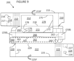
- the side panels 212, 222 may then be folded together along their respective lateral fold lines 215, 225 (according to arrows 215F, 225F) bringing the first top panel 262 (with attached handle strap 266) to overlap second top panel 242.
- Glue may be used to hold together the top panels 262, 242 in the area shown in heavy dotted lines in Figure 9 .
- Glue may also be used to hold together the ends of handle strap 266 (or reinforcement strap 268) where it contacts the flaps 258 on the outer buttress panels. (See Figures 7 and 12 ).
- the result of the folding and gluing shown on Figure 9 is a flattened tubular structure.
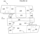
- the same structure is shown in Figure 10 , being partially opened although still generally flat in appearance.
- Figure 11 shows a perspective view from an end of the partially opened tubular structure.
- Figure 12 is a detail view of the end of top panels 242, 262 partially separated to show how the ends 266E of handle strap 266 overlap (and are eventually glued to) flaps 258 on the buttress outer panel 256. Also, the portion of handle 266 near fold line 261 is positioned over the aperture X in first top panel 242. When the handle 266 is eventually deployed (lifted), it will be anchored more securely by its attachment to flap 258, and the handle will be able to flex inward due to aperture X.
- the flattened tubular structure, this formed, may be opened into the open tubular carton 202 shown in Figure 13 .
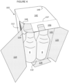
- Figure 13 shows a perspective view from an end of the carton 202 being loaded with bottles B.
- the buttress structure is still generally in a flattened state.
- the buttress structure S may be pressed inward as shown in Figure 14 , which brings the buttress outer panel 256 and buttress inner panel 252 into vertical orientation.
- the buttress inner panel 252 may rest against the necks of bottles B to prevent excessive movement of the bottles.
- the buttress outer panel 256 may be held securely in position for gluing to the side end panels 224, 210.
- the curved edge 259 of buttress floor panel 254 meanwhile provides a firm support for the upper part of curved panel 223, while the lower part of curved panel 223 will be supported by the body of the corner bottle B.
- the curved panel 223 may be formed without fear of its upper part collapsing inward for lack of internal support.
- pull holes 226 may be provided in side panel 224.
- the pull holes provide access for machine equipment to help in opening verifying proper closure of the end panels when they are glued together.
- the bottom end panel 234 may be folded upward, and the side end panel 210 may be folded inward and glued to the outer surfaces of bottom end panel 234 and buttress outer panel 256.
- the buttress floor panel 254 with its curved edge 259 may be located a distance H3 below top panel 242.
- the distance H3 may be at least 10% of the carton height H4, or at least 15% of H4, or at least 20% of H4.
- the other side end panel 224 may be folded inward and glued in place, completing the finished carton 202 (the carton 202 in Figure 16 is shown just before gluing the side panel 224 in place).
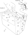
- Figure 17 shows how a user may pick up carton 202 with his hand H engaging the handle strap 266 (breaking loose the separation line 265) and lifting the handle upward.
- apertures X in top panel 242 allow the handle to pull inwardly for an easier, stronger deployment.
- Figure 18 shows a detail cross section view of the end of the deployed handle 266 and how it is attached to the rest of the carton.
- the end of handle 266 is glued between flap 217 extending at the top edge of end panel 214, and flap 258 formed in the outer wall 256 of the internal buttress.
- handle 266 When handle 266 is lifted upward, its ends pull inwardly and flex into the aperture X in the top wall 242.
- Figure 19 shows an opened carton 202.
- a user may press in the opening area 276 (defined between cut line 277 and optional score line 278) to start tearing the carton along perforation or tear lines 273 which may extend across part of the top panel 242 and continue onto the side panel 212.
- An opening may thereby be created in the top and/or side of the carton, formed by removal or hinging away of access panels 272, 279 on top panel 242 and side panel 212 respectively.
- Bottles B may be removed through this opening. After removing one or more bottles; access panels 272, 279 may be returned to their original positions by hingedly folding the panels back along fold line 275. Alternately access panels 272, 279 may be torn loose and discarded.
- FIG. 20-22 A third embodiment of a carton 302 made from a blank 300 is shown in Figures 20-22 .
- This embodiment has many features in common with the second embodiment which need not be described again. However, there are certain differences.
- the buttress outer panel 256 includes a buttress flap 258b which extends across buttress outer panel 256 and onto top pane 242 as flap 258a.
- This buttress flap 258a, 258b is somewhat longer than the buttress flap 258 of carton 202.
- a cutout area Y is provided in buttress glue panel 250 and buttress inner panel 252. The effect of the longer flap and the cutout area will be best seen in Figure 22 . Flaps 217, 227 in side walls 214, 224 may be somewhat longer than before in order to cooperate with the longer buttress flap.
- the buttress outer panel 256 may have a curved portion 256c that may better fit against or help support curved panels 213, 223.
- handle end panel 264 may have a curved portion 264c to better fit against or support curved panel 223.
- Figure 21 shows how a user may pick up carton 302 with his hand H engaging the handle strap 266 (breaking loose the separation line 265) and lifting the handle upward.
- the space in top panel 242 left by flap 258a, as well as the cutout Y in buttress inner wall 252 and buttress glue flap 250 allow the handle to pull further inward for an easier, stronger deployment.
- Figure 22 shows a detail cross section view of the end of the deployed handle 266 and how it is attached to the rest of the carton.
- the end of handle 266 is glued between flap 217 extending at the top edge of end panel 214, and flap 258b formed in the outer wall 256 of the internal buttress which continues as flap 258a struck from the top wall 242.
- flap 217 extending at the top edge of end panel 214
- flap 258b formed in the outer wall 256 of the internal buttress which continues as flap 258a struck from the top wall 242.
- handle 266 When handle 266 is lifted upward, its ends pull inwardly and flex into the interior of the buttress tube aperture. The ends may pull inwardly beyond the buttress tube itself due to the cutout Y provided in the buttress internal wall 252 and buttress glue flap 250.
- a fourth embodiment of a carton may be made from blank 400 shown in Figure 23 .
- Blank 400 is very similar to blank 300, except for placement of certain end panels.
- first side end panel 210A (hingedly connected to first side panel 212 through fold line 211) is longer in blank 400 than corresponding first side end panel 210 in blank 300.
- second side end panel 224A (hingedly connected to second side panel 222 through a curved panel 223) is shorter in blank 400 than corresponding second side end panel 224 in blank 300. Therefore, the end panels may be somewhat more symmetrical about the long axis for blank 400 than for blank 300. This may be advantageous for machinery handling the blank as it is formed into a carton.
- While the embodiments shown here use primary product containers that are generally cylindrical, it should be understood that other shapes of containers may also be accommodated within the described cartons. Also, while the described cartons have two curved corners at opposing edges of the carton, it should be understood that the cartons may be designed to have two curved corners positioned on one side or one end of the carton. Also, the carton may be designed to have one, three, or four curved corners.
- Figure 24 shows cartons with various combinations of curved corners.
- Carton 202 has already been described, and has two curved corners RD located diagonally opposite from one another on the carton.
- Carton 203 has three curved corners R3.
- Carton 204 has four curved corners R4.
- Carton 205 has a single curved corner R1.
- Carton 206 has two curved corners RS on one side of the carton.
- Carton 207 has two curved corners RE on one end of the carton.
- panels may be fastened together by other securing means for example, but not limited to, staples or other mechanical fixing means.
- hinged connection and “fold line” each refer to all manner of lines that define hinge features of the blank, facilitate folding portions of the blank with respect to one another, or otherwise indicate optimal panel folding locations in the blank or substrate of sheet material. Any reference to “hinged connection” should not be construed as necessarily referring to a single fold line only; indeed, a hinged connection can be formed from one or more fold lines.
- fold line may refer to one of the following: a scored line, an embossed line, a debossed line, a line of perforations, a line of short slits, a line of half-cuts, a single half-cut, an interrupted cut line, aligned slits, a line of short scores and any combination of the aforesaid options, without departing from the scope of the invention.
- the terms "severance line” refers to all manner of lines formed in the blank of substrate that facilitate separating portions of the blank or substrate of sheet material from one another, or otherwise that indicate optimal separation locations on the blank or substrate.
- the term “severance line” may refer to one of the following: a single half-cut, an interrupted cut, a score line, an interrupted score line, a line of perforations, a line of short cuts, a line of short slits, a line of short half cuts, and any combination of the aforementioned options.
- hinged connection, fold lines and severance lines can each includes elements that are formed in the blank or substrate of sheet material, including perforations, a line of perforations, a line of short slits, a line of half-cuts, a single half-cut, a cut line, an interrupted cut line, slits, scores, any combination thereof, and the like.
- the elements can be dimensioned and arranged to provide the desired functionality.
- a line of perforations can be dimensioned or designed with degrees of weakness to define a fold line and/or a severance line.
- the line of perforations can be designed to facilitate folding and resist breaking, to facilitate folding and facilitate breaking with more effort, or to facilitate breaking with little effort.
- in registry with refers to alignment of two or more elements in an erected carton, such as an aperture formed in a first of two overlapping panels and a second aperture formed in a second of two overlapping panels. Those elements in registry with each other may be aligned with each other in the direction of the thickness of the overlapping panels. For example, when an aperture in a first panel is "in registry with" a second aperture in a second panel that is placed in an overlapping arrangement with the first panel, an edge of the aperture may extend along at least a portion of an edge of the second aperture and may be aligned, in the direction of the thickness of the first and second panels, with the second aperture.
- cutaway refers to all manner of shapings, recesses, apertures, cuts, slots, holes and gaps which may be circular, rectangular, capsule shaped, irregular shaped and many other shapes that are pre-formed or pre-defined.
- a carton comprising:
- a carton comprising:
- top panel comprises a third curved corner
- bottom panel comprises a fourth curved corner
- a second plurality of buttress panels is attached to an edge of the top panel, at least one of the second plurality of buttress panels having a second curved edge; wherein each of the third curved corner, fourth curved corner, and second curved edge are aligned with one another.
- a blank for forming a carton comprising:
- top panel comprises a third curved corner
- bottom panel comprises a fourth curved corner
- a second plurality of buttress panels is attached to an edge of the top panel, at least one of the second plurality of buttress panels having a second curved edge; wherein each of the third curved corner and fourth curved corner are aligned with one another in the blank, and each of the third curved corner, fourth curved corner, and second curved edge aligned with one another when the blank is assembled into the carton.
Landscapes
- Engineering & Computer Science (AREA)
- Mechanical Engineering (AREA)
- Cartons (AREA)
Abstract
Description
- The present invention relates to a carton and to a blank for forming the carton more specifically, but not exclusively, to a carton having one or more curved corners, and a carrying handle for carrying the carton.
- In the field of packaging, it is often required to provide consumers with a package holding multiple primary product containers. Such multi-packs are desirable for shipping and distribution and for display of promotional information. For cost and environmental considerations, such cartons or carriers need to be formed from as little material as possible and cause as little wastage in the materials from which they are formed as possible. Another consideration is the strength of the packaging and its suitability for holding and transporting large weights of articles.
- It is desirable to provide a carton with a carrying handle for transportation by a consumer. It is desirable that the carrying handle allows the carton to be stacked, and can be deployed so as to be readily accessed by the consumer.
- Furthermore, it is often desirable to have the carton closely wrap the multiple primary product containers within the carton. This may permit the most economical use of material, and may prevent the primary product containers from moving in the carton which could damage some containers such as beverage bottles, which may clash against one another, potentially marring graphics printed on the container or on its product label. In some situations, glass bottles clashing against one another may be broken. It would therefore be advantageous to have a carton that minimizes movement of the primary product containers.
- The present invention seeks to overcome or at least mitigate the problems of the prior art.
- According to a first aspect of the present invention there is provided a carton with at least one curved corner. The curved corner may closely conform to the surface of at least one primary product container within the carton. The curved corner may be a rounded corner (e.g. shaped as a portion of a circle) and may have a radius that closely matches a major radius of the primary product container, such as its main or lower diameter.
- According to a second aspect of the present invention, the carton may contain an internal buttress or keel to help support a curved corner in an area where the primary product container has a radius less than its major radius, such as the neck of a beverage bottle. Besides supporting the curved corner, the internal buttress may support the neck of the beverage bottle and may provide a buttress structure to cooperate with machine equipment for gluing shut the carton.
- A handle structure may be provided for the carton. The handle structure may include a handle strap struck from a panel forming a carton wall and a handle strap disposed below the panel. The handle structure may include a handle reinforcing panel hingedly connected to the handle strap by a fold line.
- Within the scope of this application, it is envisaged and intended that the various aspects, embodiments, examples, features and alternatives set out in the preceding paragraphs, in the claims and/or in the following description and drawings may be taken independently or in any combination thereof. For example, features described in connection with one embodiment are applicable to all embodiments unless there is incompatibility of features.
- Exemplary embodiments of the invention will now be described with reference to the accompanying drawings, in which:
-
Figure 1 is a plan view from above of a blank for forming a carton according to a first embodiment; -
Figure 2 is a plan view from above of the blank ofFigure 1 after certain portions are folded; -
Figure 3 is a plan view from above of the blank ofFigure 2 after an additional folding step, and forming a flattened tube; -
Figure 4 is a perspective view from an end of a carton formed from the blank ofFigure 3 , during loading with primary product containers; -
Figure 5 is a perspective view from an end of the carton ofFigure 4 , with certain panels folded inward; -
Figure 6 is a perspective view from an end of the carton ofFigure 5 , in a finished state; -
Figure 7 is a plan view from above of a blank for forming a carton according to a second embodiment; -
Figure 8 is a plan view from above of the blank ofFigure 7 after certain portions are folded; -
Figure 9 is a plan view from above of the blank ofFigure 8 after an additional folding step, and forming a flattened tube; -
Figure 10 is a perspective view from above of tube ofFigure 9 , the tube now having been partially opened; -
Figure 11 is a perspective view from an end of the partially opened tube ofFigure 10 ; -
Figure 12 is a detail exploded view of certain panels of the structure ofFigure 11 ; -
Figure 13 is a perspective view from an end of a carton formed from the tube ofFigure 11 , during loading with primary product containers; -
Figure 14 is a perspective view from a side of an internal buttress being formed inside the carton ofFigure 13 ; -
Figure 15 is a perspective view from an end of the carton ofFigure 14 , with additional panels folded inward; -
Figure 16 is a perspective view from an end of the carton ofFigure 15 , in a nearly finished state; -
Figure 17 is a perspective view from a side of the carton ofFigure 16 , being lifted by its handle; -
Figure 18 is a cross-section detail view of the carton ofFigure 17 , showing the end of the handle passing through the internal buttress; -
Figure 19 is a perspective view from the side of the carton ofFigure 17 , having been opened; -
Figure 20 is a plan view from above of a blank for forming a carton according to a third embodiment; -
Figure 21 is a perspective view from the side of the carton formed from the blank ofFigure 20 , having been opened; -
Figure 22 is a cross-section detail view of the carton ofFigure 21 , showing the end of the handle passing through the internal buttress; -
Figure 23 is a plan view from above of a blank for forming a carton according to a fourth embodiment; and -
Figure 24 shows perspective views of cartons with various curved corner arrangements. - Detailed descriptions of specific embodiments of the blanks and cartons are disclosed herein. It will be understood that the disclosed embodiments are merely examples of the way in which certain aspects of the invention can be implemented and do not represent an exhaustive list of all of the ways the invention may be embodied. As used herein, the word "exemplary" is used expansively to refer to embodiments that serve as illustrations, specimens, models, or patterns. Indeed, it will be understood that the blanks and cartons described herein may be embodied in various and alternative forms. The Figures are not necessarily to scale and some features may be exaggerated or minimised to show details of particular components. Well-known components, materials or methods are not necessarily described in great detail in order to avoid obscuring the present disclosure. Any specific structural and functional details disclosed herein are not to be interpreted as limiting, but merely as a basis for the claims and as a representative basis for teaching one skilled in the art to variously employ the invention.
- Referring to
Figure 1 , there is shown a plan view of a blank 100 capable of forming acarton 102 as shown inFigure 4 , for primary products such as, but not limited to, bottles, cans or any other substantially cylindrical articles, hereinafter referred to as articles B. In particular the carton is well adapted to contain bottles B having a neck that is narrower than the main portion of the bottle. - In the embodiments detailed herein, the term "carton" refers, for the non-limiting purpose of illustrating the various features of the invention, to a container for engaging, carrying, and/or dispensing articles, such as product containers B. It is contemplated that the teachings of the invention can be applied to various product containers B, which may or may not be tapered and/or cylindrical. Exemplary containers include bottles (for example metallic, glass or plastics bottles), cans (for example aluminium cans), tins, pouches, packets and the like.
- The
blanks - In the exemplary embodiments, the
blanks Figures 1-6 , the arrangement is a 2 x 2 matrix or array and the articles are bottles. In the second and third illustrated exemplary embodiments shown inFigures 7-24 , the arrangement is a 2 x 5 matrix or array and the articles are bottles. Alternatively, theblanks - As shown in
Figure 1 , a blank 100 includes a plurality ofmain panels first side panel 112 hinged to atop panel 142 by afold line 118. Thetop panel 142 is hinged to asecond side panel 122 by afold line 128. Thesecond side panel 122 is hinged to abottom panel 132 by afold line 129. Thebottom panel 132 is hinged to aglue flap 136 by afold line 135. - The
bottom panel 132 andtop panel 142 need not be exact rectangles. In particular, each of the bottom and top panels may have at least one curved corner. In the examples herein, the top and bottom panel typically have two diagonally opposed curved corners, and two diagonally opposed 'square' corners meeting at an angle (here 90 degrees). With diagonally opposed curved corners,bottom end panels bottom panel 132 may be longitudinally offset from one another along the blank as denoted by "O1" inFigure 1 . In a similar manner, buttressouter panels top panel 142 may diagonally opposed from one another across thetop panel 142, and may be longitudinally offset from one another along the blank. - As explained later with regard to
Figure 24 , there may be more or fewer than two curved corners on each of the bottom and top panels. When there are two curved corners on each of the bottom and top panels, the curved corners may be diagonally opposed, or may be adjacent to each other along one side or one end of the carton. - The plurality of
main panels Figure 4 ) in a set up condition. - Each of the ends of the tubular structure is at least partially closed by end panels, which form end walls of the tubular structure. In the illustrated embodiment (starting from the top of
Figure 1 , running down the left side), a first end of the tubular structure is closed by a first side end panel 110 (hingedly connected tofirst side panel 112 through fold line 111), buttressouter panel 156 of a first buttress structure (hingedly connected totop panel 142 through fold line 157), a second side end panel 124 (hingedly connected tosecond side panel 122 through a curved panel 123), and bottom end panel 130 (hingedly connected tobottom panel 132 through fold line 131). - In a similar manner, a second end of the tubular structure is closed by a first side end panel 114 (hingedly connected to
first side panel 112 through a curved panel 113), buttressouter panel 156 of a second buttress structure (hingedly connected totop panel 142 through fold line 157), a second side end panel 120 (hingedly connected tosecond side panel 122 through fold line 121), and bottom end panel 134 (hingedly connected tobottom panel 132 through fold line 133). - The
curved panels blanks side end panels e.g. panels side end panels 114, 124 (whichpanels - The first and second buttress structures each include a buttress
outer panel 156 hingedly connected totop panel 142 throughfold line 157, a buttressfloor panel 154 hingedly connected to buttressouter panel 156 throughfold line 155, a buttressinner panel 152 hingedly connected to buttressfloor panel 154 throughfold line 153, and buttressglue panel 150 hingedly connected to buttressinner panel 152 throughfold line 151. In buttressouter panel 156 there may be provided anaperture 158 whose purpose will be described later. - As seen in
Figure 1 , each of the buttress structures is attached totop panel 142 through afold line 157. Acurved edge 159 on the buttress structure is joined through buttressouter panel 156 to acurved corner 149 on the top panel. The shapes ofcurved edge 159 andcurved corner 149 may at least partially be mirror images and may have the same radius. At least one ofcurved corners 149 ontop panel 142 may be aligned with acurved panel adjacent side panel curved corners top panel 142 are aligned withcurved panels curved corners bottom panel 132. The same alignment is maintained in thefinished carton 102 shown onFigure 6 . - For initial setup into a flat tubular structure, glue or adhesive may be provided for example at
points 147 on the inside surface oftop panel 142. Then as shown inFigure 2 , the buttress structures may be folded inward along fold lines 155 (according toarrows 155F) thereby forming flattened buttress tubes. - As also shown in
Figure 2 ,glue flap 136 may be folded inward along fold line 135 (according toarrow 135F) onto the inside ofbottom panel 132.Glue 137 may then be applied to the exposed surface ofglue flap 136. - As shown in
Figure 3 , the halves of the structure may then be folded together along fold line 128 (according toarrow 128F) bringing the inside offirst side panel 112 into contact with the adhesive onglue flap 136. A flattened tubular structure is thereby which may be opened into the opentubular carton 102 shown inFigure 4 . -
Figure 4 shows a perspective view from an end of thecarton 102 being loaded with bottles B. During loading the buttress structure (panels 156 and others) is still generally in a flattened state during loading as evidenced by buttressouter panel 156 being in a generally horizontal orientation. - Once loading is finished, the buttress structure may be pressed inward as shown in
Figure 5 , which brings the buttressouter panel 156 and buttressinner panel 152 into vertical orientation. Theaperture 158 may provide access for machine equipment to help in opening up the tubular buttress. The buttress may be considered a rectangular tube with its four bounding surfaces being thetop panel 142, buttressouter panel 156, buttressfloor panel 154, and buttressinner panel 152. The distance across the buttress floor panel from the buttressouter panel 156 to the buttressinner panel 152 may be chosen to substantially fill the 'empty' space between theouter walls inner panel 152 may rest against the necks of bottles B to prevent excessive movement of the bottles. By dimensioning the buttress tube to substantially fill the 'empty' space, the buttressouter panel 156 may be held securely in position for gluing to theside end panels curved edge 159 of buttressfloor panel 154 meanwhile provides a firm support for the upper part ofcurved panel 113, while the lower part ofcurved panel 113 will be supported by the body of the corner bottle B. Thus, thecurved panel 113 may be formed without fear of that the upper part of the curved panel might collapse inward for lack of internal support. The buttressfloor panel 154 and thecurved edge 159 may be located a distance H1 belowtop panel 142. The distance H1 may be at least 10% of the carton height H2, or at least 15% of H2, or at least 20% of H2. The distance H1 may be made longer for long-neck bottles B. Also, the width of the buttressfloor panel 154 between buttressouter panel 156 and buttressinner panel 152 may be chosen according to the type of bottle contained in the carton. As an example, the width of the buttressfloor panel 154 may be approximately the difference between the radius of the lower portion of the bottle and the radius of the bottle neck. - With the buttress formed into a tube, the
bottom end panel 134 may be folded upward, and theside end panel 120 may be folded inward and glued to the outer surface ofbottom end panel 134 and buttressouter panel 156. - Next, as shown in
Figure 6 , the otherside end panel 114 may be folded inward and glued in place, completing thefinished carton 102. - A second embodiment of a
carton 202 made from a blank 200 is shown inFigures 7-19 . - As shown in
Figure 7 , blank 200 includes a plurality ofmain panels Blank 200 includes a firsttop panel 242 hinged to afirst side 212 by afold line 218. Thefirst side panel 212 is hinged to abottom panel 232 by afold line 219. Thebottom panel 232 is hinged to asecond side panel 222 by afold line 228. Thesecond side panel 222 is hinged to secondtop panel 262 by afold line 229. - Each of the
first side panel 212 andsecond side panel 222 are bisected bylateral fold lines carton 202 after it has been glued into a tubular form. - The plurality of
main panels Figures 11 ,13 ) in a set up condition. - Each of the ends of the tubular structure is at least partially closed by end panels, which form end walls of the tubular structure. In the illustrated embodiment (starting from the top of
Figure 7 , running down the right side) a first end of the tubular structure is closed by a buttressouter panel 256 of a first buttress structure (hingedly connected to firsttop panel 242 through fold line 257), first side end panel 210 (hingedly connected tofirst side panel 212 through fold line 211), a bottom end panel 230 (hingedly connected tobottom panel 232 through fold line 231), second side end panel 224 (hingedly connected tosecond side panel 222 through a curved panel 223), and top end panel 264 (hingedly connected to secondtop panel 262 through fold line 263). - In a similar manner, a second end of the tubular structure is closed by buttress
outer panel 256 of a second buttress structure (hingedly connected to firsttop panel 242 through fold line 257), side end panel 214 (hingedly connected tofirst side panel 212 through curved panel 213), a bottom end panel 234 (hingedly connected tobottom panel 232 through fold line 233), side end panel 220 (hingedly connected tosecond side panel 222 through a fold line 221), and top end panel 260 (hingedly connected to secondtop panel 262 through fold line 261). - The
curved panels - The first and second buttress structures each include a buttress
outer panel 256 hingedly connected totop panel 242 throughfold line 257, a buttressfloor panel 254 hingedly connected to buttressouter panel 256 throughfold line 255, a buttressinner panel 252 hingedly connected to buttressfloor panel 254 throughfold line 253, and buttressglue panel 250 hingedly connected to buttressinner panel 252 throughfold line 251. - As seen in
Figure 7 , each of the buttress structures is attached totop panel 242 through afold line 257. For one buttress structure (at the left side ofFigure 7 ),curved corner 259 is joined through buttressouter panel 256 to acurved corner 249 on the top panel. The shapes ofcurved corners Curved corner 249 ontop panel 242 may be aligned with acurved panel 213 extending from anadjacent side panel 212. Curvedtop corner 249 may also be aligned withcurved corner 239 onbottom panel 232. The same alignment is maintained in thefinished carton 202 as shown onFigure 17 . - For the other buttress structure (at the right side of
Figure 7 ),curved corner 259 is joined through buttressouter panel 256 to acorner 249A oftop panel 242. Although thiscorner 249A could be curved, it is shown as a bevel inFigure 7 .Corner 249A may be aligned with (and in the finished carton, superimposed upon)curved corner 269 of secondtop panel 262. The shapes ofcurved corners Curved corner 269 ontop panel 262 may be aligned with acurved panel 223 extending from anadjacent side panel 212.Curved corner 269 may also be aligned withcurved corner 238 onbottom panel 232. The same alignment is maintained in thefinished carton 202 shown onFigure 16 . - After assembly, at one end of the carton the
curved corners curved corner 239 ofbottom panel 232. After assembly, at the other end of the carton thecurved corners curved corner 238 ofbottom panel 232. - For machine access during assembly of the carton, pull
holes side end panels - The help anchor the ends of the handle structure, flaps 217, 227 may be provided on the upper edge of side end flaps 214, 224, and flaps 258 may be provided in buttress
outer panels 256. Handle clearance openings X may be provided ontop panel 242adjacent flaps 258. - The second
top panel 262 may overlap the firsttop panel 242. Ahandle strap 266 may be provided in the secondtop panel 242, and separated therefrom by acut line 265 which may include temporary nicks to hold thehandle strap 266 in place. Also formed in secondtop panel 262 may be areinforcement strap 268 that may be folded underhandle strap 266 alongfold line 267. The ends of thehandle strap 266 andreinforcement strap 268 may extend onto the top end flaps 260, 264 and in thefinished carton 202 may overlap or coincide withflaps - The
handle strap 266 is defined in part by aseverance line 265 which extends longitudinally across the secondtop panel 262 and into each of thetop end panels severance line 265 terminates with a "J" or "C" shaped cut line portion. - For description purposes, blank 200 in
Figure 7 may be considered as showing the interior surface of the carton. For initial setup into a flat tubular structure, glue or adhesive may be provided for example onto the buttress glue panels 250 (or a corresponding area on first top panel 242) and onto handle reinforcement strap 268 (or a corresponding area on handle strap 266). - Next, as shown in
Figure 8 , the buttress structures may be folded inward along fold line 255 (as denoted byarrows 255F) onto firsttop panel 242, forming flattened buttress tubes. Thehandle reinforcement strap 268 may be folded inward along fold line 267 (as denoted byarrow 267F) onto thehandle strap 266, forming a two-ply handle. - As shown in
Figure 9 , theside panels lateral fold lines 215, 225 (according toarrows top panel 242. Glue may be used to hold together thetop panels Figure 9 . Glue may also be used to hold together the ends of handle strap 266 (or reinforcement strap 268) where it contacts theflaps 258 on the outer buttress panels. (SeeFigures 7 and12 ). The result of the folding and gluing shown onFigure 9 is a flattened tubular structure. The same structure is shown inFigure 10 , being partially opened although still generally flat in appearance.Figure 11 shows a perspective view from an end of the partially opened tubular structure. -
Figure 12 is a detail view of the end oftop panels handle strap 266 overlap (and are eventually glued to) flaps 258 on the buttressouter panel 256. Also, the portion ofhandle 266near fold line 261 is positioned over the aperture X in firsttop panel 242. When thehandle 266 is eventually deployed (lifted), it will be anchored more securely by its attachment toflap 258, and the handle will be able to flex inward due to aperture X. - The flattened tubular structure, this formed, may be opened into the open
tubular carton 202 shown inFigure 13 . -
Figure 13 shows a perspective view from an end of thecarton 202 being loaded with bottles B. InFigure 13 , and during loading, the buttress structure is still generally in a flattened state. Once loading is finished, the buttress structure S may be pressed inward as shown inFigure 14 , which brings the buttressouter panel 256 and buttressinner panel 252 into vertical orientation. The buttressinner panel 252 may rest against the necks of bottles B to prevent excessive movement of the bottles. The buttressouter panel 256 may be held securely in position for gluing to theside end panels - The
curved edge 259 of buttressfloor panel 254 meanwhile provides a firm support for the upper part ofcurved panel 223, while the lower part ofcurved panel 223 will be supported by the body of the corner bottle B. Thus, thecurved panel 223 may be formed without fear of its upper part collapsing inward for lack of internal support. - As shown in
Figure 15 , pullholes 226 may be provided inside panel 224. The pull holes provide access for machine equipment to help in opening verifying proper closure of the end panels when they are glued together. - With the buttress formed into a tube, the
bottom end panel 234 may be folded upward, and theside end panel 210 may be folded inward and glued to the outer surfaces ofbottom end panel 234 and buttressouter panel 256. The buttressfloor panel 254 with itscurved edge 259 may be located a distance H3 belowtop panel 242. The distance H3 may be at least 10% of the carton height H4, or at least 15% of H4, or at least 20% of H4. - Next, as shown in
Figure 16 , the otherside end panel 224 may be folded inward and glued in place, completing the finished carton 202 (thecarton 202 inFigure 16 is shown just before gluing theside panel 224 in place). -
Figure 17 shows how a user may pick upcarton 202 with his hand H engaging the handle strap 266 (breaking loose the separation line 265) and lifting the handle upward. The ends of thehandle 266, besides being attached totop end panels flaps top panel 242 allow the handle to pull inwardly for an easier, stronger deployment. -
Figure 18 shows a detail cross section view of the end of the deployedhandle 266 and how it is attached to the rest of the carton. The end ofhandle 266 is glued betweenflap 217 extending at the top edge ofend panel 214, andflap 258 formed in theouter wall 256 of the internal buttress. When handle 266 is lifted upward, its ends pull inwardly and flex into the aperture X in thetop wall 242. -
Figure 19 shows an openedcarton 202. A user may press in the opening area 276 (defined betweencut line 277 and optional score line 278) to start tearing the carton along perforation or tearlines 273 which may extend across part of thetop panel 242 and continue onto theside panel 212. An opening may thereby be created in the top and/or side of the carton, formed by removal or hinging away ofaccess panels top panel 242 andside panel 212 respectively. Bottles B may be removed through this opening. After removing one or more bottles;access panels fold line 275. Alternately accesspanels - A third embodiment of a
carton 302 made from a blank 300 is shown inFigures 20-22 . This embodiment has many features in common with the second embodiment which need not be described again. However, there are certain differences. - The buttress
outer panel 256 includes a buttressflap 258b which extends across buttressouter panel 256 and ontotop pane 242 asflap 258a. This buttressflap flap 258 ofcarton 202. To accommodate the longer flap, a cutout area Y is provided in buttressglue panel 250 and buttressinner panel 252. The effect of the longer flap and the cutout area will be best seen inFigure 22 .Flaps side walls - The buttress
outer panel 256 may have acurved portion 256c that may better fit against or help supportcurved panels end panel 264 may have acurved portion 264c to better fit against or supportcurved panel 223. -
Figure 21 shows how a user may pick upcarton 302 with his hand H engaging the handle strap 266 (breaking loose the separation line 265) and lifting the handle upward. The ends of thehandle 266, besides being attached totop end panels flaps top panel 242 left byflap 258a, as well as the cutout Y in buttressinner wall 252 and buttressglue flap 250 allow the handle to pull further inward for an easier, stronger deployment. -
Figure 22 shows a detail cross section view of the end of the deployedhandle 266 and how it is attached to the rest of the carton. The end ofhandle 266 is glued betweenflap 217 extending at the top edge ofend panel 214, andflap 258b formed in theouter wall 256 of the internal buttress which continues asflap 258a struck from thetop wall 242. When handle 266 is lifted upward, its ends pull inwardly and flex into the interior of the buttress tube aperture. The ends may pull inwardly beyond the buttress tube itself due to the cutout Y provided in the buttressinternal wall 252 and buttressglue flap 250. - A fourth embodiment of a carton may be made from blank 400 shown in
Figure 23 .Blank 400 is very similar to blank 300, except for placement of certain end panels. In particular, firstside end panel 210A (hingedly connected tofirst side panel 212 through fold line 211) is longer in blank 400 than corresponding firstside end panel 210 in blank 300. Likewise, secondside end panel 224A (hingedly connected tosecond side panel 222 through a curved panel 223) is shorter in blank 400 than corresponding secondside end panel 224 in blank 300. Therefore, the end panels may be somewhat more symmetrical about the long axis for blank 400 than for blank 300. This may be advantageous for machinery handling the blank as it is formed into a carton. - While the embodiments shown here use primary product containers that are generally cylindrical, it should be understood that other shapes of containers may also be accommodated within the described cartons. Also, while the described cartons have two curved corners at opposing edges of the carton, it should be understood that the cartons may be designed to have two curved corners positioned on one side or one end of the carton. Also, the carton may be designed to have one, three, or four curved corners.
-
Figure 24 shows cartons with various combinations of curved corners.Carton 202 has already been described, and has two curved corners RD located diagonally opposite from one another on the carton.Carton 203 has three curved corners R3.Carton 204 has four curved corners R4.Carton 205 has a single curved corner R1.Carton 206 has two curved corners RS on one side of the carton.Carton 207 has two curved corners RE on one end of the carton. - In alternative embodiments, instead of using glue or adhesive, panels may be fastened together by other securing means for example, but not limited to, staples or other mechanical fixing means.
- It can be appreciated that various changes may be made within the scope of the present invention. For example, the size and shape of the panels and apertures may be adjusted to accommodate articles of differing size or shape.
- It will be recognized that as used herein, directional references such as "top", "bottom", "base", "front", "back", "end", "side", "inner", "outer", "upper" and "lower" do not necessarily limit the respective panels to such orientation, but may merely serve to distinguish these panels from one another.
- As used herein, the terms "hinged connection" and "fold line" each refer to all manner of lines that define hinge features of the blank, facilitate folding portions of the blank with respect to one another, or otherwise indicate optimal panel folding locations in the blank or substrate of sheet material. Any reference to "hinged connection" should not be construed as necessarily referring to a single fold line only; indeed, a hinged connection can be formed from one or more fold lines.
- As used herein, the term "fold line" may refer to one of the following: a scored line, an embossed line, a debossed line, a line of perforations, a line of short slits, a line of half-cuts, a single half-cut, an interrupted cut line, aligned slits, a line of short scores and any combination of the aforesaid options, without departing from the scope of the invention.
- As used herein, the terms "severance line" refers to all manner of lines formed in the blank of substrate that facilitate separating portions of the blank or substrate of sheet material from one another, or otherwise that indicate optimal separation locations on the blank or substrate. As used herein, the term "severance line" may refer to one of the following: a single half-cut, an interrupted cut, a score line, an interrupted score line, a line of perforations, a line of short cuts, a line of short slits, a line of short half cuts, and any combination of the aforementioned options.
- It should be understood that hinged connection, fold lines and severance lines can each includes elements that are formed in the blank or substrate of sheet material, including perforations, a line of perforations, a line of short slits, a line of half-cuts, a single half-cut, a cut line, an interrupted cut line, slits, scores, any combination thereof, and the like. The elements can be dimensioned and arranged to provide the desired functionality. For example, a line of perforations can be dimensioned or designed with degrees of weakness to define a fold line and/or a severance line. The line of perforations can be designed to facilitate folding and resist breaking, to facilitate folding and facilitate breaking with more effort, or to facilitate breaking with little effort.
- The phrase "in registry with" as used herein refers to alignment of two or more elements in an erected carton, such as an aperture formed in a first of two overlapping panels and a second aperture formed in a second of two overlapping panels. Those elements in registry with each other may be aligned with each other in the direction of the thickness of the overlapping panels. For example, when an aperture in a first panel is "in registry with" a second aperture in a second panel that is placed in an overlapping arrangement with the first panel, an edge of the aperture may extend along at least a portion of an edge of the second aperture and may be aligned, in the direction of the thickness of the first and second panels, with the second aperture.
- As used herein the term "cutaway" refers to all manner of shapings, recesses, apertures, cuts, slots, holes and gaps which may be circular, rectangular, capsule shaped, irregular shaped and many other shapes that are pre-formed or pre-defined.
- The following paragraphs are not claims but statements regarding embodiments described and/or illustrated in the present disclosure:
- A carton comprising:
- a top wall;
- a bottom wall;
- a first wall extending between the top wall and bottom wall;
- a second wall extending between the top wall and bottom wall;
- a curved wall joining the first wall and second wall,
- a first buttress structure located at a joint between the top wall and one of the first and second walls; the first buttress structure having a curved edge in supporting contact with an inner surface of the curved wall.
- The carton of paragraph [0102], wherein the curved edge is located apart from the top wall.
- The carton of paragraph [0103], wherein the curved edge is located at distance below the top wall of at least 10% the height of the carton.
- The carton paragraph [0102], further comprising a second curved wall.
- The carton of paragraph [0105], wherein the second curved wall is supported by a second curved edge of the first buttress structure.
- The carton of paragraph [0105], wherein the second curved wall is supported by a second buttress structure.
- The carton of paragraph [0107], wherein the second buttress structure is located diagonally across the top wall from the first buttress structure.
- The carton of paragraph [0108], further comprising a handle strap formed in the top wall.
- The carton of paragraph [0109], wherein the top wall comprises two plies of material.
- The carton of paragraph [0109], wherein the handle comprises two plies of material.
- The carton of paragraph [0109], further comprising a plurality of containers within the carton.
- The carton of paragraph [0112], wherein the containers are bottles with a lower portion having a first diameter and an upper neck having a second diameter less than the first diameter.
- The carton of paragraph [0113], wherein at least one of the curved walls closely follows the lower portion of at least one bottle.
- The carton of paragraph [0113], wherein at least one buttress structure extends substantially between at least one of the first and second walls and at least one bottle neck.
- The carton of paragraph [0113], wherein at least one buttress structure has an inner wall in contact with at least one bottle neck.
- A carton, comprising:
- a top panel having a first curved corner;
- a bottom panel having a second curved corner;
- a plurality of buttress panels attached to an edge of the top panel, at least one of the plurality of buttress panels having a first curved edge;
- The carton of paragraph [0117], wherein the top panel comprises a third curved corner, the bottom panel comprises a fourth curved corner, and a second plurality of buttress panels is attached to an edge of the top panel, at least one of the second plurality of buttress panels having a second curved edge; wherein each of the third curved corner, fourth curved corner, and second curved edge are aligned with one another.
- A blank for forming a carton, the blank comprising:
- a top panel having a first curved corner;
- a bottom panel having a second curved corner;
- a plurality of buttress panels attached to an edge of the top panel, at least one of the plurality of buttress panels having a first curved edge;
- each of the first curved corner and second curved corner aligned with one another in the blank, and
- each of the first curved corner, second curved corner, and first curved edge aligned with one another when the blank is assembled into the carton.
- The blank of paragraph [0119], wherein the top panel comprises a third curved corner, the bottom panel comprises a fourth curved corner, and a second plurality of buttress panels is attached to an edge of the top panel, at least one of the second plurality of buttress panels having a second curved edge; wherein each of the third curved corner and fourth curved corner are aligned with one another in the blank, and each of the third curved corner, fourth curved corner, and second curved edge aligned with one another when the blank is assembled into the carton.
- The blank of paragraph [0120], wherein the first plurality of buttress panels and the second plurality of buttress panels are diagonally opposed across the top panel, and the first plurality of buttress panels and the second plurality of buttress panels are longitudinally offset from one another.
Claims (12)
- A carton comprising:a top wall;a bottom wall;a first side wall extending between the top wall and bottom wall;a second side wall extending between the top wall and bottom wall;a first end wall extending between the top wall and bottom wall;a second end wall extending between the top wall and bottom wall;a first curved wall joining the first side wall and first end wall;a second curved wall joining the first side wall and second end wall;a third curved wall joining the second side wall and first end wall; andwherein the second side wall is directly connected to the second end wall to form a square corner.
- The carton of claim 1, wherein the first curved wall is hingedly connected to the first side wall by a first hinged connection and the first curved wall is hingedly connected to the first end wall by a second hinged connection.
- The carton of claim 1, wherein the second curved wall is hingedly connected to the first side wall by a third hinged connection and the second curved wall is hingedly connected to the second end wall by a fourth hinged connection.
- The carton of claim 1, wherein the third curved wall is hingedly connected to the second side wall by a fifth hinged connection and the third curved wall is hingedly connected to the first end wall by a sixth hinged connection.
- The carton of claim 1, wherein the carton further comprises a handle strap extending across the top wall between the first and second end walls, and into at least one of the first and second end walls.
- The carton of claim 1, wherein the carton further comprises a perforation in the top wall defining at least in part an access panel for creating an opening for removal of article therethrough.
- The carton of claim 1, wherein the carton a first buttress structure located at a joint between the top wall and one of the first side wall and first end wall; the first buttress structure having a first curved edge in supporting contact with an inner surface of the first curved wall.
- The carton of claim 1, wherein the carton a second buttress structure located at a joint between the top wall and one of the first side wall and second end wall; the second buttress structure having a curved edge in supporting contact with an inner surface of the second curved wall.
- The carton of claim 7, wherein the first buttress structure has a second curved edge in supporting contact with an inner surface of the third curved wall.
- A carton comprising:a top wall;a bottom wall;a first side wall extending between the top wall and bottom wall;a second side wall extending between the top wall and bottom wall;a first end wall extending between the top wall and bottom wall;a second end wall extending between the top wall and bottom wall;a first curved wall joining the first side wall and first end wall;a second curved wall joining the first side wall and second end wall;a third curved wall joining the second side wall and first end wall; andwherein the second side wall is disposed adjacent to the second end wall such that said walls form an ordinary internal angle therebetween.
- The carton of claim 10, wherein the ordinary internal angle is a a right angle.
- A blank for forming the carton of claim 1, the blank comprising a plurality of panels for forming:a top wall;a bottom wall;a first side wall configured to extend between the top wall and bottom wall;a second side wall configured to extend between the top wall and bottom wall;a first end wall configured to extend between the top wall and bottom wall;a second end wall configured to extend between the top wall and bottom wall;a first curved wall configured to join the first side wall and first end wall;a second curved wall configured to join the first side wall and second end wall;a third curved wall configured to join the second side wall and first end wall; andwherein the second side wall configured to join to be directly connected to the second end wall to form a square corner.
Applications Claiming Priority (3)
| Application Number | Priority Date | Filing Date | Title |
|---|---|---|---|
| US201662393852P | 2016-09-13 | 2016-09-13 | |
| EP17772208.9A EP3512780A1 (en) | 2016-09-13 | 2017-09-13 | Carton and carton blank |
| PCT/US2017/051261 WO2018052929A1 (en) | 2016-09-13 | 2017-09-13 | Carton and carton blank |
Related Parent Applications (1)
| Application Number | Title | Priority Date | Filing Date |
|---|---|---|---|
| EP17772208.9A Division EP3512780A1 (en) | 2016-09-13 | 2017-09-13 | Carton and carton blank |
Publications (2)
| Publication Number | Publication Date |
|---|---|
| EP4420997A2 true EP4420997A2 (en) | 2024-08-28 |
| EP4420997A3 EP4420997A3 (en) | 2024-11-06 |
Family
ID=59955683
Family Applications (2)
| Application Number | Title | Priority Date | Filing Date |
|---|---|---|---|
| EP24186906.4A Pending EP4420997A3 (en) | 2016-09-13 | 2017-09-13 | Carton and carton blank |
| EP17772208.9A Withdrawn EP3512780A1 (en) | 2016-09-13 | 2017-09-13 | Carton and carton blank |
Family Applications After (1)
| Application Number | Title | Priority Date | Filing Date |
|---|---|---|---|
| EP17772208.9A Withdrawn EP3512780A1 (en) | 2016-09-13 | 2017-09-13 | Carton and carton blank |
Country Status (7)
| Country | Link |
|---|---|
| US (1) | US11192702B2 (en) |
| EP (2) | EP4420997A3 (en) |
| CN (1) | CN109923046B (en) |
| AU (1) | AU2017326156B2 (en) |
| CA (1) | CA3036237A1 (en) |
| MX (1) | MX395207B (en) |
| WO (1) | WO2018052929A1 (en) |
Families Citing this family (4)
| Publication number | Priority date | Publication date | Assignee | Title |
|---|---|---|---|---|
| CA3135133A1 (en) * | 2019-03-27 | 2020-10-01 | Westrock Packaging Systems, Llc | Carton and carton blank |
| US20230174281A1 (en) * | 2020-04-17 | 2023-06-08 | Westrock Packaging Systems, Llc | Article carrier and blank therefor |
| USD980069S1 (en) | 2020-07-14 | 2023-03-07 | Ball Corporation | Metallic dispensing lid |
| US12168551B2 (en) | 2021-03-01 | 2024-12-17 | Ball Corporation | Metal container and end closure with seal |
Family Cites Families (48)
| Publication number | Priority date | Publication date | Assignee | Title |
|---|---|---|---|---|
| US2062539A (en) | 1934-05-03 | 1936-12-01 | Girdler Corp | Comestible package |
| US2586301A (en) * | 1950-01-10 | 1952-02-19 | Eli N Castle | Foldable cardboard bottle carrier |
| US2751075A (en) | 1951-07-17 | 1956-06-19 | Morris Paper Mills | Carton for packaging clusters of cylindrical objects |
| US3807624A (en) | 1972-08-14 | 1974-04-30 | Mead Corp | Article carrier |
| US4015769A (en) | 1976-01-30 | 1977-04-05 | Shlomo Erlich | Cigarette box or package |
| US4143805A (en) | 1977-09-19 | 1979-03-13 | Keyes Fibre Company | Container latching arrangement |
| US4919266A (en) * | 1989-06-09 | 1990-04-24 | The C. W. Zumbiel Co. | Carton with end wall display window |
| DE4027405A1 (en) * | 1990-08-29 | 1992-03-05 | Packmaster System Entwicklung | PACKING MATERIAL CUTTING |
| GB9103388D0 (en) * | 1991-02-19 | 1991-04-03 | Assi Packaging Dev Ltd | Take away pack |
| US5197656A (en) | 1991-09-04 | 1993-03-30 | The C.W. Zumbiel Co. | Sleeve style carton |
| US5249681A (en) | 1992-01-13 | 1993-10-05 | The C. W. Zumbiel Co. | Carton dispenser system |
| FR2687634B1 (en) * | 1992-02-20 | 1994-05-13 | Otor | PROCESS AND FLAN FOR THE REALIZATION OF A CASE AROUND A LOAD, AND CASE THUS OBTAINED. |
| US5472090A (en) * | 1994-08-18 | 1995-12-05 | Riverwood International Corporation | Wrap-around carrier with partial end panels |
| US5813540A (en) * | 1994-11-10 | 1998-09-29 | Douglas Machine Limited Liability Company | Shrink film-encased double-tiered package |
| GB9500428D0 (en) | 1995-01-10 | 1995-03-01 | Mead Corp | Carton |
| US5480091A (en) * | 1995-05-11 | 1996-01-02 | The Mead Corporation | Stress-relieving arrangement for carton handles |
| US5551556A (en) * | 1995-06-14 | 1996-09-03 | Riverwood International Corporation | Wrap-around carrier with bar code blocking end panels |
| US5944253A (en) * | 1997-02-10 | 1999-08-31 | The C. W. Zumbiel Co. | Sleeve style bottle carton |
| US6202920B1 (en) * | 1997-09-11 | 2001-03-20 | The Mead Corporation | Carton blank |
| US6152359A (en) | 1999-06-15 | 2000-11-28 | Internatioal Paper Company | Oval folding carton with automatic closing |
| USD489609S1 (en) | 2000-08-18 | 2004-05-11 | Henkel Kommanditgesellschaft Auf Aktien | Package |
| AU149654S (en) | 2001-09-13 | 2002-10-24 | Reckitt Benckiser Uk Ltd | Container |
| ITBO20020138A1 (en) | 2002-03-21 | 2003-09-22 | Gd Spa | RIGID CONTAINER FOR SMOKING ITEMS AND METHOD AND MACHINE FOR ITS REALIZATION |
| USD522376S1 (en) | 2004-02-02 | 2006-06-06 | Societe Des Produits Nestle S.A. | Leaf shaped box |
| US20050199692A1 (en) * | 2004-03-05 | 2005-09-15 | Nelson Daniel J. | Blank capable of forming a container having rounded corners |
| GB0408052D0 (en) * | 2004-04-08 | 2004-05-12 | Meadwestvaco Packaging Systems | Carton and carton blank with reinforced handle structure |
| US7762450B2 (en) | 2006-02-28 | 2010-07-27 | Graphic Packaging International, Inc. | Pizza carton with curved top |
| US8777093B2 (en) | 2008-04-29 | 2014-07-15 | Rock-Tenn Shared Services, Llc | Polygonal container and blank for making the same |
| US8387784B2 (en) * | 2009-02-24 | 2013-03-05 | Graphic Packaging International, Inc. | Package for containers |
| MX2012002280A (en) * | 2009-08-28 | 2012-03-26 | Graphic Packaging Int Inc | Carton with insert. |
| ES2537545T3 (en) * | 2009-12-18 | 2015-06-09 | Graphic Packaging International, Inc. | Containers for containers |
| US20110284403A1 (en) | 2010-05-19 | 2011-11-24 | Conagra Foods Rdm, Inc. | Packaging assembly |
| US20110287146A1 (en) | 2010-05-19 | 2011-11-24 | Conagra Foods Rdm, Inc. | Packaging assembly |
| US20110287149A1 (en) | 2010-05-19 | 2011-11-24 | Conagra Foods Rdm, Inc. | Packaging assembly |
| GB201010995D0 (en) * | 2010-06-30 | 2010-08-18 | Meadwestvaco Packaging Systems | Carton and carton blank |
| US8757380B2 (en) * | 2010-10-13 | 2014-06-24 | Meadwestvaco Packaging Systems, Llc | Extended glue strips for securing cartons |
| US20130008940A1 (en) * | 2011-02-09 | 2013-01-10 | Meadwestvaco Packaging Systems, Llc | Packaging |
| MX338633B (en) | 2011-04-05 | 2016-04-26 | Sca Hygiene Prod Ab | Dispenser. |
| CA2861090C (en) * | 2012-02-16 | 2017-01-03 | Graphic Packaging International, Inc. | Carton with handle |
| US8997987B1 (en) | 2012-05-17 | 2015-04-07 | The C.W. Zumbiel Company | Wrap-around container carrier |
| MX352577B (en) * | 2012-07-17 | 2017-11-29 | Graphic Packaging Int Llc | Carton with insert. |
| US9334093B2 (en) * | 2013-05-13 | 2016-05-10 | Graphic Packaging International, Inc. | Carton with insert |
| CA2962625C (en) * | 2014-10-27 | 2019-12-03 | Graphic Packaging International, Llc | Carton for articles |
| EP3212534B1 (en) * | 2014-10-31 | 2019-08-21 | Graphic Packaging International, LLC | Carton having texture |
| BR112017006432A2 (en) * | 2014-10-31 | 2017-12-12 | Graphic Packaging Int Inc | packaging for packing at least one article, blanket for forming a packaging for packing at least one article, and method for forming a packaging |
| AU2016206942B2 (en) * | 2015-01-13 | 2019-10-10 | Westrock Packaging Systems, Llc | Carton and blank therefor |
| EP3297926B1 (en) * | 2015-05-18 | 2020-11-18 | Graphic Packaging International, LLC | Carton with opening feature |
| US10202228B2 (en) * | 2015-10-09 | 2019-02-12 | Graphic Packaging International, Llc | Carton with asymmetrical corners |
-
2017
- 2017-09-13 AU AU2017326156A patent/AU2017326156B2/en active Active
- 2017-09-13 MX MX2019002830A patent/MX395207B/en unknown
- 2017-09-13 US US16/332,726 patent/US11192702B2/en not_active Expired - Fee Related
- 2017-09-13 EP EP24186906.4A patent/EP4420997A3/en active Pending
- 2017-09-13 EP EP17772208.9A patent/EP3512780A1/en not_active Withdrawn
- 2017-09-13 WO PCT/US2017/051261 patent/WO2018052929A1/en not_active Ceased
- 2017-09-13 CN CN201780069853.2A patent/CN109923046B/en active Active
- 2017-09-13 CA CA3036237A patent/CA3036237A1/en active Pending
Also Published As
| Publication number | Publication date |
|---|---|
| WO2018052929A1 (en) | 2018-03-22 |
| CA3036237A1 (en) | 2018-03-22 |
| MX2019002830A (en) | 2019-07-01 |
| US20190256267A1 (en) | 2019-08-22 |
| EP3512780A1 (en) | 2019-07-24 |
| US11192702B2 (en) | 2021-12-07 |
| CN109923046B (en) | 2022-04-26 |
| CN109923046A (en) | 2019-06-21 |
| AU2017326156B2 (en) | 2023-08-03 |
| AU2017326156A1 (en) | 2019-03-28 |
| MX395207B (en) | 2025-03-11 |
| EP4420997A3 (en) | 2024-11-06 |
Similar Documents
| Publication | Publication Date | Title |
|---|---|---|
| US10569947B2 (en) | Carton and carton blank and a handle structure therefor | |
| US9592942B2 (en) | Carton and carton blank | |
| US9493268B2 (en) | Package with strap handle | |
| CN111315663B (en) | Carton and blank therefor | |
| AU2017326156B2 (en) | Carton and carton blank | |
| US20190300256A1 (en) | Carton and blank therefor | |
| EP3222552A1 (en) | Carton and blank therefor | |
| WO2016099969A1 (en) | Comfortable handle for carton | |
| US10377523B2 (en) | Carton and blank therefor | |
| KR20220124202A (en) | Article carriers and blanks for article carriers | |
| US20230242316A1 (en) | Carton and blank therefor | |
| US10279951B2 (en) | Carton and carton blank | |
| WO2016054466A1 (en) | Carton and carton blank | |
| WO2015054442A1 (en) | Separable carton and carton blank | |
| US20240286789A1 (en) | End closure, article carrier and blank therefor | |
| US20220363462A1 (en) | Carton and blank therefor | |
| WO2009012299A1 (en) | Sleeve carton |
Legal Events
| Date | Code | Title | Description |
|---|---|---|---|
| PUAI | Public reference made under article 153(3) epc to a published international application that has entered the european phase |
Free format text: ORIGINAL CODE: 0009012 |
|
| STAA | Information on the status of an ep patent application or granted ep patent |
Free format text: STATUS: THE APPLICATION HAS BEEN PUBLISHED |
|
| AC | Divisional application: reference to earlier application |
Ref document number: 3512780 Country of ref document: EP Kind code of ref document: P |
|
| AK | Designated contracting states |
Kind code of ref document: A2 Designated state(s): AL AT BE BG CH CY CZ DE DK EE ES FI FR GB GR HR HU IE IS IT LI LT LU LV MC MK MT NL NO PL PT RO RS SE SI SK SM TR |
|
| PUAL | Search report despatched |
Free format text: ORIGINAL CODE: 0009013 |
|
| AK | Designated contracting states |
Kind code of ref document: A3 Designated state(s): AL AT BE BG CH CY CZ DE DK EE ES FI FR GB GR HR HU IE IS IT LI LT LU LV MC MK MT NL NO PL PT RO RS SE SI SK SM TR |
|
| RIC1 | Information provided on ipc code assigned before grant |
Ipc: B65D 71/36 20060101AFI20240930BHEP |
|
| STAA | Information on the status of an ep patent application or granted ep patent |
Free format text: STATUS: REQUEST FOR EXAMINATION WAS MADE |
|
| 17P | Request for examination filed |
Effective date: 20250506 |
|
| STAA | Information on the status of an ep patent application or granted ep patent |
Free format text: STATUS: EXAMINATION IS IN PROGRESS |
|
| 17Q | First examination report despatched |
Effective date: 20260330 |