EP4420965A1 - Straddled vehicle - Google Patents
Straddled vehicle Download PDFInfo
- Publication number
- EP4420965A1 EP4420965A1 EP23214871.8A EP23214871A EP4420965A1 EP 4420965 A1 EP4420965 A1 EP 4420965A1 EP 23214871 A EP23214871 A EP 23214871A EP 4420965 A1 EP4420965 A1 EP 4420965A1
- Authority
- EP
- European Patent Office
- Prior art keywords
- damper
- cylindrical member
- pin
- seat
- vehicle body
- Prior art date
- Legal status (The legal status is an assumption and is not a legal conclusion. Google has not performed a legal analysis and makes no representation as to the accuracy of the status listed.)
- Granted
Links
Images




Classifications
-
- B—PERFORMING OPERATIONS; TRANSPORTING
- B62—LAND VEHICLES FOR TRAVELLING OTHERWISE THAN ON RAILS
- B62J—CYCLE SADDLES OR SEATS; AUXILIARY DEVICES OR ACCESSORIES SPECIALLY ADAPTED TO CYCLES AND NOT OTHERWISE PROVIDED FOR, e.g. ARTICLE CARRIERS OR CYCLE PROTECTORS
- B62J1/00—Saddles or other seats for cycles; Arrangement thereof; Component parts
- B62J1/12—Box-shaped seats; Bench-type seats, e.g. dual or twin seats
-
- B—PERFORMING OPERATIONS; TRANSPORTING
- B62—LAND VEHICLES FOR TRAVELLING OTHERWISE THAN ON RAILS
- B62J—CYCLE SADDLES OR SEATS; AUXILIARY DEVICES OR ACCESSORIES SPECIALLY ADAPTED TO CYCLES AND NOT OTHERWISE PROVIDED FOR, e.g. ARTICLE CARRIERS OR CYCLE PROTECTORS
- B62J1/00—Saddles or other seats for cycles; Arrangement thereof; Component parts
- B62J1/02—Saddles resiliently mounted on the frame; Equipment therefor, e.g. springs
- B62J1/04—Saddles capable of swinging about a horizontal pivot
Definitions
- the present invention relates to a straddled vehicle having a seat rotatably supported by a hinge on the vehicle body.
- a straddled vehicle has been known in the art that includes a seat supported on the vehicle body and a hinge for rotatably linking the seat to the vehicle body.
- Japanese Laid-Open Utility Model Publication No. S61-14946 discloses a motorcycle having a seat rotatably supported by a hinge on the vehicle body.
- an elastic member is provided between the vehicle body and the seat.
- an elastic member is arranged between the seat and the vehicle body, which is compressed from above and below. The elastic member is sandwiched between the seat and the vehicle body.
- Patent Document No. 1 Japanese Laid-Open Utility Model Publication No. S61-14946
- an elastic member is sandwiched between the seat and the vehicle body from above and below, and this elastic member suppresses the vibration in the up-down direction transmitted from the vehicle body to the seat.
- the vibration transmitted from the vehicle body to the seat is not limited to vibration in the up-down direction but also includes vibration in the front-rear direction. With the motorcycle described above, vibration in a front-rear direction cannot be sufficiently suppressed.
- the present invention has been made in view of the above, and an object thereof is to provide a straddled vehicle having a seat rotatably linked to a vehicle body by a hinge, and being capable of suppressing vibration in the up-down direction and the front-rear direction transmitted from the vehicle body to the seat.
- a straddled vehicle disclosed herein includes: a vehicle body; a seat supported on the vehicle body; and a hinge that links together the seat and the vehicle body, wherein.
- the hinge includes: a pin that is fixed to one of the vehicle body and the seat and is extending in a left-right direction; an outer cylindrical member having a cylindrical shape that is fixed to the other one of the vehicle body and the seat, into which the pin is inserted, and that is capable of rotating relative to the pin; and a damper having a cylindrical shape made of an elastic member that is inserted into the outer cylindrical member and into which the pin is inserted.
- fix refers both to direct fixing and to indirect fixing via another member.
- the damper having a cylindrical shape is interposed between the pin fixed to one of the vehicle body and the seat, and the outer cylindrical member having a cylindrical shape fixed to the other one of the vehicle body and the seat. Since the pin is inserted in the damper, the damper covers the periphery of the pin. Since the damper is inserted in the outer cylindrical member, the outer cylindrical member covers the periphery of the damper. A part of the damper is sandwiched between the pin and the outer cylindrical member from above and below, and another part of the damper is sandwiched between the pin and the outer cylindrical member from front and back.
- vibration in the up-down direction and vibration in the front-rear direction transmitted from the vehicle body to the seat are suppressed by the damper.
- vibration in the up-down direction and vibration in the front-rear direction transmitted from the vehicle body to the seat can be suppressed.
- a center axis of the outer cylindrical member may extend in the left-right direction.
- the pin may extend through inside of the outer cylindrical member.
- a center axis of the damper may extend in the left-right direction.
- the damper may extend through inside of the outer cylindrical member; and the pin may extend through inside of the damper.
- the damper may have an outer circumferential surface; and a plurality of grooves extending in the left-right direction may be formed on the outer circumferential surface.
- the damper can be inserted into the outer cylindrical member relatively easily, thereby facilitating the assembly of the hinge. Since the vibration absorbing performance of the damper is improved, vibration transmitted from the vehicle body to the seat can be more effectively suppressed.
- the number of grooves While there is no particular limitation on the number of grooves, if the number of grooves is small, the operation of inserting the damper into the outer cylindrical member tends to be not easy, and if the number of grooves is large, it tends to be more difficult for the vehicle body to stably support the pin via the damper. In view of this, the number of grooves may be 6 to 10.
- the grooves may be arranged evenly in a circumferential direction on the outer circumferential surface.
- the damper may include a first damper having a cylindrical shape and a second damper having a cylindrical shape that is arranged rightward of first damper.
- a gap may be provided between the first damper and the second damper.
- the first damper may include a first cylindrical portion and a first flange portion that extends outward in a radial direction from a left end of the first cylindrical portion.
- the second damper may include a second cylindrical portion and a second flange portion that extends outward in a radial direction from a right end of the second cylindrical portion.
- the first damper can be positioned by inserting the first damper from the left side of the outer cylindrical member and placing the first flange portion against the left end of the outer cylindrical member.
- the second damper can be positioned by inserting the second damper from the right side of the outer cylindrical member and placing the second flange portion against the right end of the outer cylindrical member. This further facilitates the assembly of the hinge.
- the straddled vehicle may include an inner cylindrical member that is inserted into the damper and into which the pin is inserted.
- One of the pin and the inner cylindrical member may rotatably support the other one of the pin and the inner cylindrical member.
- one of the pin and the outer cylindrical member can be stably and rotatably supported relative to the other.
- the seat can be stably and rotatably supported by the vehicle body.
- the straddled vehicle may be configured so that the pin and the outer cylindrical member rotate relative to each other, thereby allowing the seat to rotate relative to the vehicle body with the pin serving as an axis of rotation.
- the damper may be made of a rubber having a hardness of 30 to 60 degrees.
- the inner diameter of the damper may be 7 to 12 mm.
- the outer diameter of the damper may be 15 to 24 mm.
- the damper may have an inner circumferential surface; and a plurality of grooves extending in the left-right direction may be formed on the inner circumferential surface.
- vibration transmitted from the vehicle body to the seat can be more effectively suppressed.
- a straddled vehicle having a seat rotatably linked to a vehicle body by a hinge, and being capable of suppressing vibration in the up-down direction and the front-rear direction transmitted from the vehicle body to the seat.
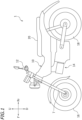
- FIG. 1 is a side view of a motorcycle 1, which is an example of a straddled vehicle.
- front, rear, left, right, up and down refer to these directions as seen from a virtual rider seated on a seat 20 while the motorcycle 1 is standing upright on a horizontal surface with no rider and no load thereon, unless specified otherwise.
- the motorcycle 1 includes a vehicle body 10, an internal combustion engine (hereinafter referred to as "engine") 14 as a driving source for traveling, a front wheel 16, a rear wheel 18, a steering handle 12, and a seat 20 supported on the vehicle body 10.
- engine internal combustion engine
- the vehicle body 10 is supported on the front wheel 16 and the rear wheel 18.
- the steering handle 12 is connected to the front wheel 16 via a steering shaft (not shown) and a front fork 7. By turning the steering handle 12 left and right, the direction of the front wheel 16 can be changed to left and right.
- the engine 14 is supported on the vehicle body 10.
- the rear wheel 18 is linked to the engine 14 so that power can be transmitted therebetween.
- the rear wheel 18 is the drive wheel and is driven by the driving force of the engine 14.
- the seat 20 is arranged rearward of the steering handle 12.
- the seat 20 is arranged upward of the engine 14.
- the motorcycle 1 includes a hinge 30 that links together the seat 20 and the vehicle body 10.
- the seat 20 is linked by the hinge 30 so that the seat 20 can be turned up and down relative to the vehicle body 10.
- the hinge 30 is located at the front end portion of the seat 20.
- a fuel tank 11 is arranged downward of the seat 20.
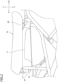
- the seat 20 is configured so that the seat 20 can be repositioned by the hinge 30 to the horizontal position (see FIG. 2 ), in which the rider is seated and to the vertical position (see FIG. 3 ) in which there is an opening upward of the fuel tank 11.
- the front end portion of the seat 20 is supported on the vehicle body 10 via the hinge 30.
- a supported portion 28, which is supported on the vehicle body 10, is provided at the rear portion of the seat 20.
- the front portion and the rear portion of the seat 20 refer to portions that are respectively forward and rearward of the middle position of the seat 20 in the front-rear direction. In the present embodiment, the front portion and the rear portion of the seat 20 are supported on the vehicle body 10.
- FIG. 4 is a front view of the hinge 30 and the surrounding structure.
- FIG. 5 is a side view of the hinge 30.
- FIG. 6 is a cross-sectional view of the hinge 30 taken along line VI-VI of FIG. 4 .
- FIG. 7 is a cross-sectional view of the hinge 30 taken along line VII-VII of FIG. 5 .
- a link member 23 is fixed to a bottom plate 21 of the seat 20 by a bolt 22A and a nut 22B.
- the link member 23 includes an outer cylindrical member 23A having a cylindrical shape, an arm member 23B, and a fastening member 23C.
- the center axis of the outer cylindrical member 23A extends in the left-right direction.
- the arm member 23B extends upward from the outer cylindrical member 23A.
- the fastening member 23C has a hole (not shown) through which the bolt 22A is inserted.
- the outer cylindrical member 23A, the arm member 23B and the fastening member 23C are a single-piece part.
- the link member 23 is made of a metal such as iron, stainless steel or aluminum. Note however that the outer cylindrical member 23A, the arm member 23B and the fastening member 23C may be separate from each other. There is no particular limitation on the material of the link member 23.
- a damper 33 having a cylindrical shape made of an elastic material is inserted inside the outer cylindrical member 23A.
- the damper 33 extends through the inside of the outer cylindrical member 23A.
- the center axis of the damper 33 extends in the left-right direction.
- the damper 33 may be a single-piece part, the damper 33 is composed of two dampers having a cylindrical shape, i.e., a first damper 31 and a second damper 32, in the present embodiment.
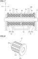
- FIG. 8 is a perspective view of the first damper 31.
- the first damper 31 includes a first cylindrical portion 31a and a first flange portion 31b extending outward in the radial direction from the left end of the first cylindrical portion 31a.
- the outer diameter of the first flange portion 31b is larger than the outer diameter of the first cylindrical portion 31a.
- a plurality of grooves 33s extending in the axial direction of the first cylindrical portion 31a are formed on the outer circumferential surface of the first cylindrical portion 31a. In the present embodiment, since the axial direction of the first damper 31 coincides with the left-right direction, the grooves 33s extend in the left-right direction.
- the grooves 33s are formed to have a semicircular cross-sectional shape (see FIG. 6 ).
- the cross-sectional shape of the grooves 33s there is no particular limitation on the cross-sectional shape of the grooves 33s, and it may be a triangular shape or a rectangular shape, for example.
- the grooves 33s all have the same shape, but the shape of any one groove 33s may be different from the shape of any other groove 33s. While there is no particular limitation on the number of grooves 33s, it is 6 to 10, for example.
- eight grooves 33s are formed on the first cylindrical portion 31a.
- the eight grooves 33s are arranged evenly in the circumferential direction of the outer circumferential surface of the first cylindrical portion 31a.
- the grooves 33s are arranged every 45 degrees around the axis of the first cylindrical section 31a.
- the material of the damper 33 is an elastic material capable of absorbing vibration.
- the first damper 31 is made of rubber with a hardness of 30 to 60 degrees.
- the dimension of the damper 33 is 7 to 12 mm, for example, and the outer diameter of damper 33 is 15 to 24 mm, for example.
- the outer diameter of the damper 33 refers to the outer diameter excluding the flange portion.
- the inner diameter of the first cylindrical portion 31a is 7 to 12 mm, for example, and the outer diameter of the first cylindrical portion 31a is 15 to 24 mm, for example.
- first damper 31 and the second damper 32 may be different from each other, but they are identical in the present embodiment. Therefore, a detailed description of the second damper 32 will be omitted.
- first damper 31 and the second damper 32 are arranged in left-right symmetry.
- the first damper 31 is inserted into the left portion of the outer cylindrical member 23A
- the second damper 32 is inserted into the right portion of the outer cylindrical member 23A.
- the second damper 32 is arranged rightward of the first damper 31.
- the second damper 32 includes a second cylindrical portion 32a, and a second flange portion 32b extending outward in the radial direction from the right end of the second cylindrical portion 32a.
- a plurality of grooves 33s extending in the left-right direction are formed on the outer circumference surface of the second cylindrical portion 32a. Eight grooves 33s are arranged evenly in the circumferential direction on the outer circumferential surface of the second cylindrical portion 32a (see FIG. 6 ).
- the first damper 31 is inserted into the outer cylindrical member 23A from the left side and the second damper 32 is inserted into the outer cylindrical member 23A from the right side.
- the first flange portion 31b of the first damper 31 contacts the left end of the outer cylindrical member 23A, thereby positioning the first damper 31 relative to the outer cylindrical member 23A.
- the second flange portion 32b of the second damper 32 contacts the right end of the outer cylindrical member 23A, thereby positioning the second damper 32 relative to the outer cylindrical member 23A.
- first damper 31 and the second damper 32 are separated from each other, forming a gap 35 between the first damper 31 and the second damper 32.
- an inner cylindrical member 40 having a cylindrical shape is inserted inside the damper 33.
- the inner cylindrical member 40 extends in the left-right direction.
- the inner cylindrical member 40 is arranged inside the outer cylindrical member 23A, and the damper 33 is interposed between the outer cylindrical member 23A and the inner cylindrical member 40.
- the material of the inner cylindrical member 40 it is made of a metal such as iron, stainless steel or aluminum in the present embodiment.
- a pin 50 extending in the left-right direction is inserted inside the inner cylindrical member 40.
- the pin 50 extends through the inside of the inner cylindrical member 40. Since the inner cylindrical member 40 is arranged inside the outer cylindrical member 23A, the pin 50 extends through the inside of the outer cylindrical member 23A. Since the inner cylindrical member 40 is inserted into the damper 33, the pin 50 is arranged inside the damper 33. The pin 50 is inserted into the damper 33. The pin 50 extends through the inside of the damper 33. While the pin 50 may have a cylindrical shape, it is formed in a columnar shape in the present embodiment. While there is no particular limitation on the material of the pin 50, it is made of a metal such as iron, stainless steel or aluminum in the present embodiment.
- the vehicle body 10 includes a support bracket 13.
- the pin 50 is fitted into the support bracket 13, and is fixed to the support bracket 13.
- the pin 50 rotatably supports the inner cylindrical member 40.
- the inner cylindrical member 40, the damper 33 and the outer cylindrical member 23A, together as a single piece, can rotate relative to the pin 50.
- the pin 50 rotatably supports the inner cylindrical member 40, the damper 33 and the outer cylindrical member 23A.
- the outer cylindrical member 23A is rotatable relative to the pin 50.
- the motorcycle 1 is configured such that the pin 50 and the outer cylindrical member 23A can rotate relative to each other, thereby allowing the seat 20 to rotate relative to the vehicle body 10 with the pin 50 serving as the axis of rotation.
- the outer cylindrical member 23A of the link member 23 fixed to the seat 20 rotates relative to the pin 50 fixed to the support bracket 13 of the vehicle body 10. This causes the seat 20 to rotate up and down between the horizontal position (see FIG. 2 ) and the vertical position (see FIG. 3 ).
- the damper 33 having a cylindrical shape is arranged between the pin 50 fixed to the vehicle body 10 and the outer cylindrical member 23A fixed to the seat 20. Since the pin 50 is inserted in the damper 33, the damper 33 covers the periphery of the pin 50. Since the damper 33 is inserted in the outer cylindrical member 23A, the outer cylindrical member 23A covers the periphery of the damper 33. A part of the damper 33 is sandwiched between the pin 50 and the outer cylindrical member 23A from above and below, and another part of the damper 33 is sandwiched between the pin 50 and the outer cylindrical member 23A from front and back.
- vibration in the up-down direction and vibration in the front-rear direction transmitted from the vehicle body 10 to the seat 20 are both suppressed by the damper 33.
- vibration in the up-down direction and vibration in the front-rear direction transmitted from the vehicle body 10 to the seat 20 can be suppressed.
- a plurality of grooves 33s extending in the left-right direction are formed on the outer circumferential surface of the damper 33 (see FIG. 8 ). This makes it easier for the damper 33 to deform when inserting the damper 33 into the outer cylindrical member 23A.
- the damper 33 can be inserted into the outer cylindrical member 23A relatively easily, thereby facilitating the assembly of the hinge 30. Since the vibration absorbing performance of the damper 33 is improved, vibration transmitted from the vehicle body 10 to the seat 20 can be more effectively suppressed.
- the number of grooves 33s is 6 to 10.
- the grooves 33s are arranged evenly in the circumferential direction on the outer circumferential surface of the damper 33. This makes it easier for the damper 33 to deform, thereby facilitating the operation of inserting the damper 33 into the outer cylindrical member 23A. It is possible to effectively suppress vibration transmitted from the vehicle body 10 to the seat 20.
- the damper 33 includes the first damper 31 and the second damper 32 (see FIG. 7 ). By inserting the first damper 31 from the left side of the outer cylindrical member 23A and inserting the second damper 32 from the right side of the outer cylindrical member 23A, the damper 33 can be easily inserted inside the outer cylindrical member 23A. This further facilitates the assembly of the hinge 30.
- the gap 35 is provided between the first damper 31 and the second damper 32. Even if there is a dimension error, for the left-right direction, in the outer cylindrical member 23A, the first damper 31 or the second damper 32, it is possible to easily arrange the first damper 31 and the second damper 32 inside the outer cylindrical member 23A. For example, even if the length of the first damper 31 in the left-right direction is slightly longer than the design value, it will only result in the gap 35 being smaller, and it is possible to easily arrange the first and second dampers 31 and 32 inside the outer cylindrical member 23A. This facilitates the assembly of the hinge 30.
- the first damper 31 includes the first cylindrical portion 31a and the first flange portion 31b
- the second damper 32 includes the second cylindrical portion 32a and the second flange portion 32b.
- the first damper 31 can be positioned by inserting the first damper 31 from the left side of the outer cylindrical member 23A and placing the first flange portion 31b against the left end of the outer cylindrical member 23A.
- the second damper 32 can be positioned by inserting the second damper 32 from the right side of the outer cylindrical member 23A and placing the second flange portion 32b against the right end of the outer cylindrical member 23A. This further facilitates the assembly of the hinge 30.
- the hinge 30 includes the inner cylindrical member 40 inserted into the damper 33 and into which the pin 50 is inserted.
- the pin 50 rotatably supports the inner cylindrical member 40.
- the outer cylindrical member 23A can be stably and rotatably supported by the pin 50.
- the seat 20 can be stably and rotatably supported by the vehicle body 10.
- the damper 33 is made of a rubber having a hardness of 30 to 60 degrees.
- the damper 33 has an appropriate hardness. Therefore, it is possible to desirably suppress the vibration transmitted from the vehicle body 10 to the seat 20, and the seat 20 can be stably supported by the vehicle body 10.
- the inner circumferential surface of the damper 33 (the first damper 31 and the second damper 32) is a smooth surface, but as shown in FIG. 9 , a groove 33t extending in the left-right direction may be formed on the inner circumferential surface of the damper 33. This can further improve the vibration absorbing performance of the damper 33. Thus, the vibration transmitted from the vehicle body 10 to the seat 20 can be effectively suppressed.
- the outer cylindrical member 23A of the hinge 30 is fixed to the seat 20 and the pin 50 is fixed to the vehicle body 10.
- the outer cylindrical member 23A may be fixed to the vehicle body 10 and the pin 50 may be fixed to the seat 20.
- the pin 50 rotates relative to the outer cylindrical member 23A, causing the seat 20 to rotate up and down between the horizontal position and the vertical position.
- the hinge 30 is connected to the front end of the seat 20, and the seat 20 is configured to rotate forward and upward while moving from the horizontal position to the vertical position.
- the location of the hinge 30 is not limited to the front end portion of the seat 20.
- the hinge 30 may be connected to the rear end portion of the seat 20 and the seat 20 may be configured to rotate rearward and upward while moving from the horizontal position to the vertical position.
- a plurality of grooves 33s are formed evenly in the circumferential direction on the outer circumferential surface of the damper 33. Note however that the grooves 33s do not need to be formed evenly in the circumferential direction.
- the number of grooves in the upper portion or the lower portion of the outer circumferential surface of the damper 33 may be greater than the number of grooves in the front portion or the rear portion. This makes the vibration absorbing capacity of the damper 33 in the front-rear direction greater than the vibration absorbing capacity in the up-down direction. Thus, the vibration transmitted to the seat 20 can be effectively suppressed in motorcycles where the vibration in the front-rear direction is greater than the vibration in the up-down direction.
- the upper portion of the outer circumferential surface of the damper 33 is the portion of the damper 33 that is less than 45 degrees forward and rearward of the vertical line extending upward from the axis of the damper 33.
- the lower portion of the outer circumferential surface of the damper 33 is the portion of the damper 33 that is less than 45 degrees forward and rearward of the vertical line extending downward from the axis of the damper 33.
- the front portion of the outer circumferential surface of the damper 33 is the portion of the damper 33 that is less than 45 degrees upward and downward of the horizontal line extending forward from the axis of the damper 33.
- the rear portion of the outer circumferential surface of the damper 33 is the portion of the damper 33 that is less than 45 degrees upward and downward of the horizontal line extending backward from the axis of the damper 33.
- the number of grooves on the front portion or the rear portion of the outer circumferential surface of the damper 33 may be greater than the number of grooves on the upper portion or the lower portion. This makes the vibration absorbing capacity of the damper 33 in the up-down direction greater than the vibration absorbing capacity in the front-rear direction. Thus, the vibration transmitted to the seat 20 can be effectively suppressed in motorcycles where the vibration in the up-down direction is greater than the vibration in the front-rear direction.
- the average groove width of the grooves in the upper portion or the lower portion of the outer circumferential surface of the damper 33 may be larger than the average groove width of the grooves in the front portion or the rear portion. This makes the vibration absorbing capacity of the damper 33 in the front-rear direction greater than the vibration absorbing capacity in the up-down direction. Thus, the vibration transmitted to the seat 20 can be effectively suppressed in motorcycles where the vibration in the front-rear direction is greater than the vibration in the up-down direction.
- the average groove width of the grooves in the front portion or the rear portion of the outer circumferential surface of the damper 33 may be larger than the average groove width of the grooves in the upper portion or the lower portion.
- the vibration absorbing capacity of the damper 33 in the up-down direction is greater than the vibration absorbing capacity in the front-rear direction.
- the vibration transmitted to the seat 20 can be effectively suppressed in motorcycles where the vibration in the up-down direction is greater than the vibration in the front-rear direction.
- the average groove depth of the grooves in the upper portion or the lower portion of the outer circumferential surface of the damper 33 may be greater than the average groove depth of the grooves in the front portion or the rear portion.
- the vibration absorbing capacity of the damper 33 in the front-rear direction is greater than the vibration absorbing capacity in the up-down direction.
- the vibration transmitted to the seat 20 can be effectively suppressed in motorcycles 1 where the vibration in the front-rear direction is greater than the vibration in the up-down direction.
- the average groove depth of the grooves in the front portion or the rear portion of the outer circumferential surface of the damper 33 may be greater than the average groove depth of the grooves in the upper portion or the lower portion.
- the vibration absorbing capacity of the damper 33 in the up-down direction is greater than the vibration absorbing capacity in the front-rear direction.
- the vibration transmitted to the seat 20 can be effectively suppressed in motorcycles 1 where the vibration in the up-down direction is greater than the vibration in the front-rear direction.
- the number of grooves 33s may be one. There may be no grooves 33s on the outer circumferential surface of the damper 33.
- damper 33 includes the first damper 31 and the second damper 32 in the embodiment described above, the damper 33 may include three or more dampers.
- the damper 33 may be a single damper.
- gap 35 is provided between the first damper 31 and the second damper 32 in the embodiment described above, the gap 35 may be absent.
- first damper 31 includes the first flange portion 31b and the second damper 32 includes the second flange portion 32b in the embodiment described above, the first flange portion 31b and/or the second flange portion 32b may be absent.
- the damper 33 may be arranged entirely on the inner side of the outer cylindrical member 23A, or a portion thereof may be arranged on the outer side of the outer cylindrical member 23A.
- the inner cylindrical member 40 is provided between the damper 33 and the pin 50 in the embodiment described above, the inner cylindrical member 40 may be absent as long as the damper 33 and the pin 50 can easily rotate relative to each other.
- the vehicle parts downward of the seat 20 are not limited to the fuel tank 11.
- a storage box may be arranged downward of the seat 20.
- the upward of the storage box can be opened so that items can be placed in and out of the storage box by rotating the seat 20 from the horizontal position to the vertical position.
- a straddled vehicle refers to a vehicle that is straddled by a rider.
- the straddled vehicle is not limited to the motorcycle 1.
- the straddled vehicle may be an auto tricycle, an ATV (All Terrain Vehicle), or a snowmobile, for example.
Landscapes
- Engineering & Computer Science (AREA)
- Mechanical Engineering (AREA)
- Vibration Prevention Devices (AREA)
Abstract
Description
- The present invention relates to a straddled vehicle having a seat rotatably supported by a hinge on the vehicle body.
- A straddled vehicle has been known in the art that includes a seat supported on the vehicle body and a hinge for rotatably linking the seat to the vehicle body. For example,
Japanese Laid-Open Utility Model Publication No. S61-14946 - While the motorcycle is running, vibration from the engine is transmitted to the seat. To reduce the vibration transmitted from the vehicle body to the seat, an elastic member is provided between the vehicle body and the seat. In the motorcycle disclosed in
Japanese Laid-Open Utility Model Publication No. S61-14946 - Patent Document No. 1:
Japanese Laid-Open Utility Model Publication No. S61-14946 - With the motorcycle described above, an elastic member is sandwiched between the seat and the vehicle body from above and below, and this elastic member suppresses the vibration in the up-down direction transmitted from the vehicle body to the seat. However, the vibration transmitted from the vehicle body to the seat is not limited to vibration in the up-down direction but also includes vibration in the front-rear direction. With the motorcycle described above, vibration in a front-rear direction cannot be sufficiently suppressed.
- The present invention has been made in view of the above, and an object thereof is to provide a straddled vehicle having a seat rotatably linked to a vehicle body by a hinge, and being capable of suppressing vibration in the up-down direction and the front-rear direction transmitted from the vehicle body to the seat.
- A straddled vehicle disclosed herein includes: a vehicle body; a seat supported on the vehicle body; and a hinge that links together the seat and the vehicle body, wherein. The hinge includes: a pin that is fixed to one of the vehicle body and the seat and is extending in a left-right direction; an outer cylindrical member having a cylindrical shape that is fixed to the other one of the vehicle body and the seat, into which the pin is inserted, and that is capable of rotating relative to the pin; and a damper having a cylindrical shape made of an elastic member that is inserted into the outer cylindrical member and into which the pin is inserted. Note that the term "fix" as used herein refers both to direct fixing and to indirect fixing via another member.
- With the straddled vehicle described above, the damper having a cylindrical shape is interposed between the pin fixed to one of the vehicle body and the seat, and the outer cylindrical member having a cylindrical shape fixed to the other one of the vehicle body and the seat. Since the pin is inserted in the damper, the damper covers the periphery of the pin. Since the damper is inserted in the outer cylindrical member, the outer cylindrical member covers the periphery of the damper. A part of the damper is sandwiched between the pin and the outer cylindrical member from above and below, and another part of the damper is sandwiched between the pin and the outer cylindrical member from front and back. Thus, vibration in the up-down direction and vibration in the front-rear direction transmitted from the vehicle body to the seat are suppressed by the damper. With the straddled vehicle described above, vibration in the up-down direction and vibration in the front-rear direction transmitted from the vehicle body to the seat can be suppressed.
- A center axis of the outer cylindrical member may extend in the left-right direction.
- The pin may extend through inside of the outer cylindrical member.
- A center axis of the damper may extend in the left-right direction.
- The damper may extend through inside of the outer cylindrical member; and the pin may extend through inside of the damper.
- The damper may have an outer circumferential surface; and a plurality of grooves extending in the left-right direction may be formed on the outer circumferential surface.
- This makes it easier for the damper to deform when inserting the damper into the outer cylindrical member. The damper can be inserted into the outer cylindrical member relatively easily, thereby facilitating the assembly of the hinge. Since the vibration absorbing performance of the damper is improved, vibration transmitted from the vehicle body to the seat can be more effectively suppressed.
- While there is no particular limitation on the number of grooves, if the number of grooves is small, the operation of inserting the damper into the outer cylindrical member tends to be not easy, and if the number of grooves is large, it tends to be more difficult for the vehicle body to stably support the pin via the damper. In view of this, the number of grooves may be 6 to 10.
- The grooves may be arranged evenly in a circumferential direction on the outer circumferential surface.
- This facilitates the operation of inserting the damper into the outer cylindrical member.
- The damper may include a first damper having a cylindrical shape and a second damper having a cylindrical shape that is arranged rightward of first damper.
- This facilitates the operation of inserting the damper into the outer cylindrical member. For example, by inserting the first damper from the left side of the outer cylindrical member and inserting the second damper from the right side of the outer cylindrical member, the damper can be easily inserted inside the outer cylindrical member. This further facilitates the assembly of the hinge.
- A gap may be provided between the first damper and the second damper.
- Thus, even if there is a dimension error, for the left-right direction, in the outer cylindrical member, the first damper or the second damper, it is possible to easily arrange the first damper and the second damper inside the outer cylindrical member. This facilitates the assembly of the hinge.
- The first damper may include a first cylindrical portion and a first flange portion that extends outward in a radial direction from a left end of the first cylindrical portion. The second damper may include a second cylindrical portion and a second flange portion that extends outward in a radial direction from a right end of the second cylindrical portion.
- Thus, the first damper can be positioned by inserting the first damper from the left side of the outer cylindrical member and placing the first flange portion against the left end of the outer cylindrical member. Similarly, the second damper can be positioned by inserting the second damper from the right side of the outer cylindrical member and placing the second flange portion against the right end of the outer cylindrical member. This further facilitates the assembly of the hinge.
- The straddled vehicle may include an inner cylindrical member that is inserted into the damper and into which the pin is inserted. One of the pin and the inner cylindrical member may rotatably support the other one of the pin and the inner cylindrical member.
- Thus, with the inner cylindrical member interposed between the damper and the pin, one of the pin and the outer cylindrical member can be stably and rotatably supported relative to the other. Thus, the seat can be stably and rotatably supported by the vehicle body.
- The straddled vehicle may be configured so that the pin and the outer cylindrical member rotate relative to each other, thereby allowing the seat to rotate relative to the vehicle body with the pin serving as an axis of rotation.
- The damper may be made of a rubber having a hardness of 30 to 60 degrees.
- Therefore, it is possible to desirably suppress the vibration transmitted from the vehicle body to the seat, and the seat can be stably supported by the vehicle body.
- The inner diameter of the damper may be 7 to 12 mm. The outer diameter of the damper may be 15 to 24 mm.
- The damper may have an inner circumferential surface; and a plurality of grooves extending in the left-right direction may be formed on the inner circumferential surface.
- Thus, since the vibration absorbing performance of the damper is improved, vibration transmitted from the vehicle body to the seat can be more effectively suppressed.
- According to the present invention, it is possible to provide a straddled vehicle having a seat rotatably linked to a vehicle body by a hinge, and being capable of suppressing vibration in the up-down direction and the front-rear direction transmitted from the vehicle body to the seat.
-
-
FIG. 1 is a left side view of a motorcycle according to one embodiment. -
FIG. 2 is a side view of a hinge and a surrounding structure when the seat is in the horizontal position. -
FIG. 3 is a side view of the hinge and the surrounding structure when the seat is in the vertical position. -
FIG. 4 is a front view of the hinge and the surrounding structure. -
FIG. 5 is a side view of the hinge. -
FIG. 6 is a cross-sectional view of the hinge taken along line VI-VI ofFIG. 4 . -
FIG. 7 is a cross-sectional view of the hinge taken along line VII-VII ofFIG. 5 . -
FIG. 8 is a perspective view of a first damper. -
FIG. 9 is a lateral cross-sectional view of a damper, etc., according to another embodiment. -
FIG. 10 is a lateral cross-sectional view of a damper according to another embodiment. -
FIG. 11 is a lateral cross-sectional view of a damper according to another embodiment. - An embodiment of a straddled vehicle will now be described with reference to the drawings.
FIG. 1 is a side view of amotorcycle 1, which is an example of a straddled vehicle. - The terms front, rear, left, right, up and down, as used in the description below, refer to these directions as seen from a virtual rider seated on a
seat 20 while themotorcycle 1 is standing upright on a horizontal surface with no rider and no load thereon, unless specified otherwise. The designations F, Rr, L, R, U and D, as used in the figures, refer to front, rear, left, right, up and down, respectively. - The
motorcycle 1 includes avehicle body 10, an internal combustion engine (hereinafter referred to as "engine") 14 as a driving source for traveling, afront wheel 16, arear wheel 18, asteering handle 12, and aseat 20 supported on thevehicle body 10. - The
vehicle body 10 is supported on thefront wheel 16 and therear wheel 18. The steering handle 12 is connected to thefront wheel 16 via a steering shaft (not shown) and afront fork 7. By turning the steering handle 12 left and right, the direction of thefront wheel 16 can be changed to left and right. Theengine 14 is supported on thevehicle body 10. Therear wheel 18 is linked to theengine 14 so that power can be transmitted therebetween. Therear wheel 18 is the drive wheel and is driven by the driving force of theengine 14. - The
seat 20 is arranged rearward of thesteering handle 12. Theseat 20 is arranged upward of theengine 14. - As shown in
FIG. 2 andFIG. 3 , themotorcycle 1 includes ahinge 30 that links together theseat 20 and thevehicle body 10. Theseat 20 is linked by thehinge 30 so that theseat 20 can be turned up and down relative to thevehicle body 10. Thehinge 30 is located at the front end portion of theseat 20. In the present embodiment, afuel tank 11 is arranged downward of theseat 20. Theseat 20 is configured so that theseat 20 can be repositioned by thehinge 30 to the horizontal position (seeFIG. 2 ), in which the rider is seated and to the vertical position (seeFIG. 3 ) in which there is an opening upward of thefuel tank 11. - As shown in
FIG. 2 , the front end portion of theseat 20 is supported on thevehicle body 10 via thehinge 30. A supportedportion 28, which is supported on thevehicle body 10, is provided at the rear portion of theseat 20. Note that the front portion and the rear portion of theseat 20 refer to portions that are respectively forward and rearward of the middle position of theseat 20 in the front-rear direction. In the present embodiment, the front portion and the rear portion of theseat 20 are supported on thevehicle body 10. - Next, details of the
hinge 30 will be described.FIG. 4 is a front view of thehinge 30 and the surrounding structure.FIG. 5 is a side view of thehinge 30.FIG. 6 is a cross-sectional view of thehinge 30 taken along line VI-VI ofFIG. 4 .FIG. 7 is a cross-sectional view of thehinge 30 taken along line VII-VII ofFIG. 5 . - As shown in
FIG. 6 , alink member 23 is fixed to abottom plate 21 of theseat 20 by abolt 22A and anut 22B. Thelink member 23 includes an outercylindrical member 23A having a cylindrical shape, anarm member 23B, and afastening member 23C. As shown inFIG. 4 , the center axis of the outercylindrical member 23A extends in the left-right direction. When theseat 20 is in the horizontal position, thearm member 23B extends upward from the outercylindrical member 23A. Thefastening member 23C has a hole (not shown) through which thebolt 22A is inserted. Here, the outercylindrical member 23A, thearm member 23B and thefastening member 23C are a single-piece part. Thelink member 23 is made of a metal such as iron, stainless steel or aluminum. Note however that the outercylindrical member 23A, thearm member 23B and thefastening member 23C may be separate from each other. There is no particular limitation on the material of thelink member 23. - As shown in
FIG. 7 , adamper 33 having a cylindrical shape made of an elastic material is inserted inside the outercylindrical member 23A. Thedamper 33 extends through the inside of the outercylindrical member 23A. The center axis of thedamper 33 extends in the left-right direction. While thedamper 33 may be a single-piece part, thedamper 33 is composed of two dampers having a cylindrical shape, i.e., afirst damper 31 and asecond damper 32, in the present embodiment.FIG. 8 is a perspective view of thefirst damper 31. - The
first damper 31 includes a firstcylindrical portion 31a and afirst flange portion 31b extending outward in the radial direction from the left end of the firstcylindrical portion 31a. The outer diameter of thefirst flange portion 31b is larger than the outer diameter of the firstcylindrical portion 31a. A plurality ofgrooves 33s extending in the axial direction of the firstcylindrical portion 31a are formed on the outer circumferential surface of the firstcylindrical portion 31a. In the present embodiment, since the axial direction of thefirst damper 31 coincides with the left-right direction, thegrooves 33s extend in the left-right direction. In the present embodiment, thegrooves 33s are formed to have a semicircular cross-sectional shape (seeFIG. 6 ). However, there is no particular limitation on the cross-sectional shape of thegrooves 33s, and it may be a triangular shape or a rectangular shape, for example. In the present embodiment, thegrooves 33s all have the same shape, but the shape of any onegroove 33s may be different from the shape of anyother groove 33s. While there is no particular limitation on the number ofgrooves 33s, it is 6 to 10, for example. In the present embodiment, eightgrooves 33s are formed on the firstcylindrical portion 31a. The eightgrooves 33s are arranged evenly in the circumferential direction of the outer circumferential surface of the firstcylindrical portion 31a. Thegrooves 33s are arranged every 45 degrees around the axis of the firstcylindrical section 31a. - There is no particular limitation on the material of the
damper 33 as long as thedamper 33 is an elastic material capable of absorbing vibration. In the present embodiment, thefirst damper 31 is made of rubber with a hardness of 30 to 60 degrees. There is no particular limitation on the dimension of thedamper 33. The inner diameter of thedamper 33 is 7 to 12 mm, for example, and the outer diameter ofdamper 33 is 15 to 24 mm, for example. Note that the outer diameter of thedamper 33 refers to the outer diameter excluding the flange portion. Here, the inner diameter of the firstcylindrical portion 31a is 7 to 12 mm, for example, and the outer diameter of the firstcylindrical portion 31a is 15 to 24 mm, for example. - The shape, the material or the dimensions of the
first damper 31 and thesecond damper 32 may be different from each other, but they are identical in the present embodiment. Therefore, a detailed description of thesecond damper 32 will be omitted. As shown inFIG. 7 , thefirst damper 31 and thesecond damper 32 are arranged in left-right symmetry. Thefirst damper 31 is inserted into the left portion of the outercylindrical member 23A, and thesecond damper 32 is inserted into the right portion of the outercylindrical member 23A. Thesecond damper 32 is arranged rightward of thefirst damper 31. Thesecond damper 32 includes a secondcylindrical portion 32a, and asecond flange portion 32b extending outward in the radial direction from the right end of the secondcylindrical portion 32a. A plurality ofgrooves 33s extending in the left-right direction are formed on the outer circumference surface of the secondcylindrical portion 32a. Eightgrooves 33s are arranged evenly in the circumferential direction on the outer circumferential surface of the secondcylindrical portion 32a (seeFIG. 6 ). - As shown in
FIG. 7 , thefirst damper 31 is inserted into the outercylindrical member 23A from the left side and thesecond damper 32 is inserted into the outercylindrical member 23A from the right side. Thefirst flange portion 31b of thefirst damper 31 contacts the left end of the outercylindrical member 23A, thereby positioning thefirst damper 31 relative to the outercylindrical member 23A. Similarly, thesecond flange portion 32b of thesecond damper 32 contacts the right end of the outercylindrical member 23A, thereby positioning thesecond damper 32 relative to the outercylindrical member 23A. Where thefirst flange portion 31b contacts the left end of the outercylindrical member 23A and thesecond flange portion 32b contacts the right end of the outercylindrical member 23A, thefirst damper 31 and thesecond damper 32 are separated from each other, forming agap 35 between thefirst damper 31 and thesecond damper 32. - As shown in
FIG. 7 , an innercylindrical member 40 having a cylindrical shape is inserted inside thedamper 33. The innercylindrical member 40 extends in the left-right direction. The innercylindrical member 40 is arranged inside the outercylindrical member 23A, and thedamper 33 is interposed between the outercylindrical member 23A and the innercylindrical member 40. While there is no particular limitation on the material of the innercylindrical member 40, it is made of a metal such as iron, stainless steel or aluminum in the present embodiment. - A
pin 50 extending in the left-right direction is inserted inside the innercylindrical member 40. Thepin 50 extends through the inside of the innercylindrical member 40. Since the innercylindrical member 40 is arranged inside the outercylindrical member 23A, thepin 50 extends through the inside of the outercylindrical member 23A. Since the innercylindrical member 40 is inserted into thedamper 33, thepin 50 is arranged inside thedamper 33. Thepin 50 is inserted into thedamper 33. Thepin 50 extends through the inside of thedamper 33. While thepin 50 may have a cylindrical shape, it is formed in a columnar shape in the present embodiment. While there is no particular limitation on the material of thepin 50, it is made of a metal such as iron, stainless steel or aluminum in the present embodiment. - As shown in
FIG. 5 , thevehicle body 10 includes asupport bracket 13. As shown inFIG. 7 , thepin 50 is fitted into thesupport bracket 13, and is fixed to thesupport bracket 13. Thepin 50 rotatably supports the innercylindrical member 40. The innercylindrical member 40, thedamper 33 and the outercylindrical member 23A, together as a single piece, can rotate relative to thepin 50. Thepin 50 rotatably supports the innercylindrical member 40, thedamper 33 and the outercylindrical member 23A. The outercylindrical member 23A is rotatable relative to thepin 50. - The
motorcycle 1 is configured such that thepin 50 and the outercylindrical member 23A can rotate relative to each other, thereby allowing theseat 20 to rotate relative to thevehicle body 10 with thepin 50 serving as the axis of rotation. In the present embodiment, the outercylindrical member 23A of thelink member 23 fixed to theseat 20 rotates relative to thepin 50 fixed to thesupport bracket 13 of thevehicle body 10. This causes theseat 20 to rotate up and down between the horizontal position (seeFIG. 2 ) and the vertical position (seeFIG. 3 ). - As described above, with the
motorcycle 1 according to the present embodiment, thedamper 33 having a cylindrical shape is arranged between thepin 50 fixed to thevehicle body 10 and the outercylindrical member 23A fixed to theseat 20. Since thepin 50 is inserted in thedamper 33, thedamper 33 covers the periphery of thepin 50. Since thedamper 33 is inserted in the outercylindrical member 23A, the outercylindrical member 23A covers the periphery of thedamper 33. A part of thedamper 33 is sandwiched between thepin 50 and the outercylindrical member 23A from above and below, and another part of thedamper 33 is sandwiched between thepin 50 and the outercylindrical member 23A from front and back. Thus, vibration in the up-down direction and vibration in the front-rear direction transmitted from thevehicle body 10 to theseat 20 are both suppressed by thedamper 33. With themotorcycle 1 according to the present embodiment, vibration in the up-down direction and vibration in the front-rear direction transmitted from thevehicle body 10 to theseat 20 can be suppressed. - According to the present embodiment, a plurality of
grooves 33s extending in the left-right direction are formed on the outer circumferential surface of the damper 33 (seeFIG. 8 ). This makes it easier for thedamper 33 to deform when inserting thedamper 33 into the outercylindrical member 23A. Thedamper 33 can be inserted into the outercylindrical member 23A relatively easily, thereby facilitating the assembly of thehinge 30. Since the vibration absorbing performance of thedamper 33 is improved, vibration transmitted from thevehicle body 10 to theseat 20 can be more effectively suppressed. - In the present embodiment, the number of
grooves 33s is 6 to 10. Thegrooves 33s are arranged evenly in the circumferential direction on the outer circumferential surface of thedamper 33. This makes it easier for thedamper 33 to deform, thereby facilitating the operation of inserting thedamper 33 into the outercylindrical member 23A. It is possible to effectively suppress vibration transmitted from thevehicle body 10 to theseat 20. - According to the present embodiment, the
damper 33 includes thefirst damper 31 and the second damper 32 (seeFIG. 7 ). By inserting thefirst damper 31 from the left side of the outercylindrical member 23A and inserting thesecond damper 32 from the right side of the outercylindrical member 23A, thedamper 33 can be easily inserted inside the outercylindrical member 23A. This further facilitates the assembly of thehinge 30. - According to the present embodiment, the
gap 35 is provided between thefirst damper 31 and thesecond damper 32. Even if there is a dimension error, for the left-right direction, in the outercylindrical member 23A, thefirst damper 31 or thesecond damper 32, it is possible to easily arrange thefirst damper 31 and thesecond damper 32 inside the outercylindrical member 23A. For example, even if the length of thefirst damper 31 in the left-right direction is slightly longer than the design value, it will only result in thegap 35 being smaller, and it is possible to easily arrange the first andsecond dampers cylindrical member 23A. This facilitates the assembly of thehinge 30. - According to the present embodiment, the
first damper 31 includes the firstcylindrical portion 31a and thefirst flange portion 31b, and thesecond damper 32 includes the secondcylindrical portion 32a and thesecond flange portion 32b. Thefirst damper 31 can be positioned by inserting thefirst damper 31 from the left side of the outercylindrical member 23A and placing thefirst flange portion 31b against the left end of the outercylindrical member 23A. Similarly, thesecond damper 32 can be positioned by inserting thesecond damper 32 from the right side of the outercylindrical member 23A and placing thesecond flange portion 32b against the right end of the outercylindrical member 23A. This further facilitates the assembly of thehinge 30. - According to the present embodiment, the
hinge 30 includes the innercylindrical member 40 inserted into thedamper 33 and into which thepin 50 is inserted. Thepin 50 rotatably supports the innercylindrical member 40. Thus, with the innercylindrical member 40 interposed between thedamper 33 and thepin 50, the outercylindrical member 23A can be stably and rotatably supported by thepin 50. Thus, theseat 20 can be stably and rotatably supported by thevehicle body 10. - According to the present embodiment, the
damper 33 is made of a rubber having a hardness of 30 to 60 degrees. Thedamper 33 has an appropriate hardness. Therefore, it is possible to desirably suppress the vibration transmitted from thevehicle body 10 to theseat 20, and theseat 20 can be stably supported by thevehicle body 10. - Although one embodiment of the straddled vehicle has been described above, the embodiment described above is merely an example, and various other embodiments are possible. Examples of other embodiments will be briefly described below.
- In the embodiment described above, the inner circumferential surface of the damper 33 (the
first damper 31 and the second damper 32) is a smooth surface, but as shown inFIG. 9 , agroove 33t extending in the left-right direction may be formed on the inner circumferential surface of thedamper 33. This can further improve the vibration absorbing performance of thedamper 33. Thus, the vibration transmitted from thevehicle body 10 to theseat 20 can be effectively suppressed. - In the embodiment described above, the outer
cylindrical member 23A of thehinge 30 is fixed to theseat 20 and thepin 50 is fixed to thevehicle body 10. However, the outercylindrical member 23A may be fixed to thevehicle body 10 and thepin 50 may be fixed to theseat 20. In this case, thepin 50 rotates relative to the outercylindrical member 23A, causing theseat 20 to rotate up and down between the horizontal position and the vertical position. - In the embodiment described above, the
hinge 30 is connected to the front end of theseat 20, and theseat 20 is configured to rotate forward and upward while moving from the horizontal position to the vertical position. However, the location of thehinge 30 is not limited to the front end portion of theseat 20. For example, thehinge 30 may be connected to the rear end portion of theseat 20 and theseat 20 may be configured to rotate rearward and upward while moving from the horizontal position to the vertical position. - In the embodiment described above, a plurality of
grooves 33s are formed evenly in the circumferential direction on the outer circumferential surface of thedamper 33. Note however that thegrooves 33s do not need to be formed evenly in the circumferential direction. - As shown in
FIG. 10 , the number of grooves in the upper portion or the lower portion of the outer circumferential surface of thedamper 33 may be greater than the number of grooves in the front portion or the rear portion. This makes the vibration absorbing capacity of thedamper 33 in the front-rear direction greater than the vibration absorbing capacity in the up-down direction. Thus, the vibration transmitted to theseat 20 can be effectively suppressed in motorcycles where the vibration in the front-rear direction is greater than the vibration in the up-down direction. Note that the upper portion of the outer circumferential surface of thedamper 33 is the portion of thedamper 33 that is less than 45 degrees forward and rearward of the vertical line extending upward from the axis of thedamper 33. The lower portion of the outer circumferential surface of thedamper 33 is the portion of thedamper 33 that is less than 45 degrees forward and rearward of the vertical line extending downward from the axis of thedamper 33. The front portion of the outer circumferential surface of thedamper 33 is the portion of thedamper 33 that is less than 45 degrees upward and downward of the horizontal line extending forward from the axis of thedamper 33. The rear portion of the outer circumferential surface of thedamper 33 is the portion of thedamper 33 that is less than 45 degrees upward and downward of the horizontal line extending backward from the axis of thedamper 33. - As shown in
FIG. 11 , the number of grooves on the front portion or the rear portion of the outer circumferential surface of thedamper 33 may be greater than the number of grooves on the upper portion or the lower portion. This makes the vibration absorbing capacity of thedamper 33 in the up-down direction greater than the vibration absorbing capacity in the front-rear direction. Thus, the vibration transmitted to theseat 20 can be effectively suppressed in motorcycles where the vibration in the up-down direction is greater than the vibration in the front-rear direction. - The average groove width of the grooves in the upper portion or the lower portion of the outer circumferential surface of the
damper 33 may be larger than the average groove width of the grooves in the front portion or the rear portion. This makes the vibration absorbing capacity of thedamper 33 in the front-rear direction greater than the vibration absorbing capacity in the up-down direction. Thus, the vibration transmitted to theseat 20 can be effectively suppressed in motorcycles where the vibration in the front-rear direction is greater than the vibration in the up-down direction. - The average groove width of the grooves in the front portion or the rear portion of the outer circumferential surface of the
damper 33 may be larger than the average groove width of the grooves in the upper portion or the lower portion. Thus, the vibration absorbing capacity of thedamper 33 in the up-down direction is greater than the vibration absorbing capacity in the front-rear direction. Thus, the vibration transmitted to theseat 20 can be effectively suppressed in motorcycles where the vibration in the up-down direction is greater than the vibration in the front-rear direction. - The average groove depth of the grooves in the upper portion or the lower portion of the outer circumferential surface of the
damper 33 may be greater than the average groove depth of the grooves in the front portion or the rear portion. Thus, the vibration absorbing capacity of thedamper 33 in the front-rear direction is greater than the vibration absorbing capacity in the up-down direction. Thus, the vibration transmitted to theseat 20 can be effectively suppressed inmotorcycles 1 where the vibration in the front-rear direction is greater than the vibration in the up-down direction. - The average groove depth of the grooves in the front portion or the rear portion of the outer circumferential surface of the
damper 33 may be greater than the average groove depth of the grooves in the upper portion or the lower portion. Thus, the vibration absorbing capacity of thedamper 33 in the up-down direction is greater than the vibration absorbing capacity in the front-rear direction. Thus, the vibration transmitted to theseat 20 can be effectively suppressed inmotorcycles 1 where the vibration in the up-down direction is greater than the vibration in the front-rear direction. - While a plurality of
grooves 33s are formed on the outer circumferential surface of thedamper 33 in the embodiment described above, the number ofgrooves 33s may be one. There may be nogrooves 33s on the outer circumferential surface of thedamper 33. - While the
damper 33 includes thefirst damper 31 and thesecond damper 32 in the embodiment described above, thedamper 33 may include three or more dampers. Thedamper 33 may be a single damper. - While the
gap 35 is provided between thefirst damper 31 and thesecond damper 32 in the embodiment described above, thegap 35 may be absent. - While the
first damper 31 includes thefirst flange portion 31b and thesecond damper 32 includes thesecond flange portion 32b in the embodiment described above, thefirst flange portion 31b and/or thesecond flange portion 32b may be absent. Thedamper 33 may be arranged entirely on the inner side of the outercylindrical member 23A, or a portion thereof may be arranged on the outer side of the outercylindrical member 23A. - While the inner
cylindrical member 40 is provided between thedamper 33 and thepin 50 in the embodiment described above, the innercylindrical member 40 may be absent as long as thedamper 33 and thepin 50 can easily rotate relative to each other. - While the
fuel tank 11 is arranged downward of theseat 20 in the embodiment described above, the vehicle parts downward of theseat 20 are not limited to thefuel tank 11. For example, a storage box may be arranged downward of theseat 20. In this case, the upward of the storage box can be opened so that items can be placed in and out of the storage box by rotating theseat 20 from the horizontal position to the vertical position. - A straddled vehicle refers to a vehicle that is straddled by a rider. The straddled vehicle is not limited to the
motorcycle 1. The straddled vehicle may be an auto tricycle, an ATV (All Terrain Vehicle), or a snowmobile, for example. - 1: Motorcycle (straddled vehicle), 10: Vehicle body, 20: Seat, 23A: Outer cylindrical member, 30: Hinge, 31: First damper, 31a: First cylindrical portion, 31b: First flange portion, 32: Second damper, 32a: Second cylindrical portion, 32b: Second flange portion, 33: Damper, 33s: Groove, 33t: Groove, 35: Gap, 40: Inner cylindrical member, 50: Pin
Claims (16)
- A straddled vehicle (1) comprising:a vehicle body (10);a seat (20) supported on the vehicle body (10); anda hinge (30) that links together the seat (20) and the vehicle body (10), wherein:
the hinge (30) including:a pin (50) that is fixed to one of the vehicle body (10) and the seat (20) and is extending in a left-right direction;an outer cylindrical member (23A) having a cylindrical shape that is fixed to the other one of the vehicle body (10) and the seat (20), into which the pin (50) is inserted, and that is capable of rotating relative to the pin (50); anda damper (33) having a cylindrical shape made of an elastic member that is inserted into the outer cylindrical member (23A) and into which the pin (50) is inserted. - The straddled vehicle according to claim 1, wherein a center axis of the outer cylindrical member (23A) extends in the left-right direction.
- The straddled vehicle according to claim 1 or 2, wherein the pin (50) extends through inside of the outer cylindrical member (23A).
- The straddled vehicle according to any one of claims 1 to 3, wherein a center axis of the damper (33) extends in the left-right direction.
- The straddled vehicle according to any one of claims 1 to 4, wherein:the damper (33) extends through inside of the outer cylindrical member (23A); andthe pin (50) extends through inside of the damper (33).
- The straddled vehicle according to claim 1, wherein:the damper (33) has an outer circumferential surface; anda plurality of grooves (33s) extending in the left-right direction are formed on the outer circumferential surface.
- The straddled vehicle according to claim 6, wherein the number of grooves (33s) is 6 to 10.
- The straddled vehicle according to claim 6 or 7, wherein the grooves (33s) are arranged evenly in a circumferential direction on the outer circumferential surface.
- The straddled vehicle according to any one of claims 1 to 8, wherein the damper (33) includes a first damper (31) having a cylindrical shape and a second damper (32) having a cylindrical shape that is arranged rightward of first damper (31).
- The straddled vehicle according to claim 9, wherein a gap (35) is provided between the first damper (31) and the second damper (32).
- The straddled vehicle according to claim 9 or 10, wherein:the first damper (31) includes a first cylindrical portion (31a) and a first flange portion (31b) that extends outward in a radial direction from a left end of the first cylindrical portion (31a); andthe second damper (32) includes a second cylindrical portion (32a) and a second flange portion (32b) that extends outward in a radial direction from a right end of the second cylindrical portion (32a).
- The straddled vehicle according to any one of claims 1 to 11, comprising:an inner cylindrical member (40) that is inserted into the damper (33) and into which the pin (50) is inserted; andone of the pin (50) and the inner cylindrical member (40) rotatably supports the other one of the pin (50) and the inner cylindrical member (40).
- The straddled vehicle according to any one of claims 1 to 12, wherein the pin (50) and the outer cylindrical member (23A) rotate relative to each other, thereby allowing the seat (20) to rotate relative to the vehicle body (10) with the pin (50) serving as an axis of rotation.
- The straddled vehicle according to any one of claims 1 to 13, wherein the damper (33) is made of a rubber having a hardness of 30 to 60 degrees.
- The straddled vehicle according to any one of claims 1 to 14, wherein:an inner diameter of the damper (33) is 7 to 12 mm; andan outer diameter of the damper (33) is 15 to 24 mm.
- The straddled vehicle according to any one of claims 1 to 15, wherein:the damper (33) has an inner circumferential surface; anda plurality of grooves (33t) extending in the left-right direction are formed on the inner circumferential surface.
Applications Claiming Priority (1)
| Application Number | Priority Date | Filing Date | Title |
|---|---|---|---|
| JP2023026057A JP2024119274A (en) | 2023-02-22 | 2023-02-22 | Saddle-type vehicle |
Publications (2)
| Publication Number | Publication Date |
|---|---|
| EP4420965A1 true EP4420965A1 (en) | 2024-08-28 |
| EP4420965B1 EP4420965B1 (en) | 2025-04-23 |
Family
ID=89122083
Family Applications (1)
| Application Number | Title | Priority Date | Filing Date |
|---|---|---|---|
| EP23214871.8A Active EP4420965B1 (en) | 2023-02-22 | 2023-12-07 | Straddled vehicle |
Country Status (2)
| Country | Link |
|---|---|
| EP (1) | EP4420965B1 (en) |
| JP (1) | JP2024119274A (en) |
Citations (5)
| Publication number | Priority date | Publication date | Assignee | Title |
|---|---|---|---|---|
| JPS53122864U (en) * | 1977-03-07 | 1978-09-29 | ||
| JPS6114946U (en) | 1984-07-03 | 1986-01-28 | 育三 長野 | Container for washing |
| CN2908291Y (en) * | 2005-08-03 | 2007-06-06 | 光阳工业股份有限公司 | Motorcycle Seat Cushion Automatic Lifting Device |
| US20080178427A1 (en) * | 2007-01-26 | 2008-07-31 | Startech Co., Ltd. | Hinge mechanism for motor vehicle |
| CN101450690A (en) * | 2007-12-07 | 2009-06-10 | 雅马哈发动机株式会社 | Seat pad positioning device of automatic bicycle |
-
2023
- 2023-02-22 JP JP2023026057A patent/JP2024119274A/en active Pending
- 2023-12-07 EP EP23214871.8A patent/EP4420965B1/en active Active
Patent Citations (5)
| Publication number | Priority date | Publication date | Assignee | Title |
|---|---|---|---|---|
| JPS53122864U (en) * | 1977-03-07 | 1978-09-29 | ||
| JPS6114946U (en) | 1984-07-03 | 1986-01-28 | 育三 長野 | Container for washing |
| CN2908291Y (en) * | 2005-08-03 | 2007-06-06 | 光阳工业股份有限公司 | Motorcycle Seat Cushion Automatic Lifting Device |
| US20080178427A1 (en) * | 2007-01-26 | 2008-07-31 | Startech Co., Ltd. | Hinge mechanism for motor vehicle |
| CN101450690A (en) * | 2007-12-07 | 2009-06-10 | 雅马哈发动机株式会社 | Seat pad positioning device of automatic bicycle |
Also Published As
| Publication number | Publication date |
|---|---|
| JP2024119274A (en) | 2024-09-03 |
| EP4420965B1 (en) | 2025-04-23 |
Similar Documents
| Publication | Publication Date | Title |
|---|---|---|
| JP5046994B2 (en) | Side stand mounting structure for motorcycles | |
| JP6502297B2 (en) | Saddle-ride type vehicle | |
| US10464632B2 (en) | Straddled vehicle | |
| JP6476224B2 (en) | Rear fender support structure for saddle-ride type vehicles | |
| EP3936423B1 (en) | Straddled vehicle | |
| JP7694697B2 (en) | Motor Mount System | |
| EP2572897B1 (en) | Wheel for motorcycle | |
| EP4420965B1 (en) | Straddled vehicle | |
| JP2003341579A (en) | Motorcycle or tricycle body frame and motorcycle or tricycle equipped with the body frame | |
| JP2017047764A (en) | Saddle-riding type vehicle | |
| JP2020032985A (en) | Saddle-ride type vehicle and side stand bracket | |
| JP6464478B2 (en) | Front wheel support frame structure for saddle-ride type vehicles | |
| JP6241747B2 (en) | Front two-wheel saddle-type swing vehicle | |
| EP1950132B1 (en) | Vehicle | |
| CN103287536A (en) | Electric power unit for vehicle | |
| JP2016060470A (en) | Front twin-wheel type saddle riding type swing vehicle | |
| JP7149125B2 (en) | Straddle vehicle | |
| JP7369750B2 (en) | saddle type vehicle | |
| EP3456618A1 (en) | Motorcycle | |
| CN112572051B (en) | Wheel structure | |
| EP3992471B1 (en) | Resin part having attachment hole, assembly part including the same, and straddled vehicle | |
| EP3366561B1 (en) | Rear bracket structure of straddled vehicle and method for assembling the same | |
| JP2024164798A (en) | Saddle-type vehicle and connecting bracket used therefor | |
| JP2025064135A (en) | Drive device and vehicle | |
| JP2012149625A (en) | Engine bearing structure |
Legal Events
| Date | Code | Title | Description |
|---|---|---|---|
| PUAI | Public reference made under article 153(3) epc to a published international application that has entered the european phase |
Free format text: ORIGINAL CODE: 0009012 |
|
| STAA | Information on the status of an ep patent application or granted ep patent |
Free format text: STATUS: THE APPLICATION HAS BEEN PUBLISHED |
|
| STAA | Information on the status of an ep patent application or granted ep patent |
Free format text: STATUS: REQUEST FOR EXAMINATION WAS MADE |
|
| AK | Designated contracting states |
Kind code of ref document: A1 Designated state(s): AL AT BE BG CH CY CZ DE DK EE ES FI FR GB GR HR HU IE IS IT LI LT LU LV MC ME MK MT NL NO PL PT RO RS SE SI SK SM TR |
|
| 17P | Request for examination filed |
Effective date: 20240726 |
|
| RBV | Designated contracting states (corrected) |
Designated state(s): AL AT BE BG CH CY CZ DE DK EE ES FI FR GB GR HR HU IE IS IT LI LT LU LV MC ME MK MT NL NO PL PT RO RS SE SI SK SM TR |
|
| P01 | Opt-out of the competence of the unified patent court (upc) registered |
Free format text: CASE NUMBER: APP_51296/2024 Effective date: 20240911 |
|
| GRAP | Despatch of communication of intention to grant a patent |
Free format text: ORIGINAL CODE: EPIDOSNIGR1 |
|
| STAA | Information on the status of an ep patent application or granted ep patent |
Free format text: STATUS: GRANT OF PATENT IS INTENDED |
|
| RIC1 | Information provided on ipc code assigned before grant |
Ipc: B62J 1/12 20060101ALI20241014BHEP Ipc: B62J 1/04 20060101AFI20241014BHEP |
|
| INTG | Intention to grant announced |
Effective date: 20241115 |
|
| GRAS | Grant fee paid |
Free format text: ORIGINAL CODE: EPIDOSNIGR3 |
|
| GRAA | (expected) grant |
Free format text: ORIGINAL CODE: 0009210 |
|
| STAA | Information on the status of an ep patent application or granted ep patent |
Free format text: STATUS: THE PATENT HAS BEEN GRANTED |
|
| AK | Designated contracting states |
Kind code of ref document: B1 Designated state(s): AL AT BE BG CH CY CZ DE DK EE ES FI FR GB GR HR HU IE IS IT LI LT LU LV MC ME MK MT NL NO PL PT RO RS SE SI SK SM TR |
|
| REG | Reference to a national code |
Ref country code: GB Ref legal event code: FG4D |
|
| REG | Reference to a national code |
Ref country code: CH Ref legal event code: EP |
|
| REG | Reference to a national code |
Ref country code: DE Ref legal event code: R096 Ref document number: 602023003081 Country of ref document: DE |
|
| REG | Reference to a national code |
Ref country code: IE Ref legal event code: FG4D |
|
| REG | Reference to a national code |
Ref country code: NL Ref legal event code: MP Effective date: 20250423 |
|
| PG25 | Lapsed in a contracting state [announced via postgrant information from national office to epo] |
Ref country code: NL Free format text: LAPSE BECAUSE OF FAILURE TO SUBMIT A TRANSLATION OF THE DESCRIPTION OR TO PAY THE FEE WITHIN THE PRESCRIBED TIME-LIMIT Effective date: 20250423 |
|
| REG | Reference to a national code |
Ref country code: AT Ref legal event code: MK05 Ref document number: 1787533 Country of ref document: AT Kind code of ref document: T Effective date: 20250423 |
|
| PG25 | Lapsed in a contracting state [announced via postgrant information from national office to epo] |
Ref country code: FI Free format text: LAPSE BECAUSE OF FAILURE TO SUBMIT A TRANSLATION OF THE DESCRIPTION OR TO PAY THE FEE WITHIN THE PRESCRIBED TIME-LIMIT Effective date: 20250423 Ref country code: ES Free format text: LAPSE BECAUSE OF FAILURE TO SUBMIT A TRANSLATION OF THE DESCRIPTION OR TO PAY THE FEE WITHIN THE PRESCRIBED TIME-LIMIT Effective date: 20250423 Ref country code: PT Free format text: LAPSE BECAUSE OF FAILURE TO SUBMIT A TRANSLATION OF THE DESCRIPTION OR TO PAY THE FEE WITHIN THE PRESCRIBED TIME-LIMIT Effective date: 20250825 |
|
| REG | Reference to a national code |
Ref country code: LT Ref legal event code: MG9D |
|
| PG25 | Lapsed in a contracting state [announced via postgrant information from national office to epo] |
Ref country code: GR Free format text: LAPSE BECAUSE OF FAILURE TO SUBMIT A TRANSLATION OF THE DESCRIPTION OR TO PAY THE FEE WITHIN THE PRESCRIBED TIME-LIMIT Effective date: 20250724 Ref country code: NO Free format text: LAPSE BECAUSE OF FAILURE TO SUBMIT A TRANSLATION OF THE DESCRIPTION OR TO PAY THE FEE WITHIN THE PRESCRIBED TIME-LIMIT Effective date: 20250723 |
|
| PG25 | Lapsed in a contracting state [announced via postgrant information from national office to epo] |
Ref country code: PL Free format text: LAPSE BECAUSE OF FAILURE TO SUBMIT A TRANSLATION OF THE DESCRIPTION OR TO PAY THE FEE WITHIN THE PRESCRIBED TIME-LIMIT Effective date: 20250423 |
|
| PG25 | Lapsed in a contracting state [announced via postgrant information from national office to epo] |
Ref country code: BG Free format text: LAPSE BECAUSE OF FAILURE TO SUBMIT A TRANSLATION OF THE DESCRIPTION OR TO PAY THE FEE WITHIN THE PRESCRIBED TIME-LIMIT Effective date: 20250423 |
|
| PG25 | Lapsed in a contracting state [announced via postgrant information from national office to epo] |
Ref country code: HR Free format text: LAPSE BECAUSE OF FAILURE TO SUBMIT A TRANSLATION OF THE DESCRIPTION OR TO PAY THE FEE WITHIN THE PRESCRIBED TIME-LIMIT Effective date: 20250423 |
|
| PG25 | Lapsed in a contracting state [announced via postgrant information from national office to epo] |
Ref country code: AT Free format text: LAPSE BECAUSE OF FAILURE TO SUBMIT A TRANSLATION OF THE DESCRIPTION OR TO PAY THE FEE WITHIN THE PRESCRIBED TIME-LIMIT Effective date: 20250423 |
|
| PG25 | Lapsed in a contracting state [announced via postgrant information from national office to epo] |
Ref country code: RS Free format text: LAPSE BECAUSE OF FAILURE TO SUBMIT A TRANSLATION OF THE DESCRIPTION OR TO PAY THE FEE WITHIN THE PRESCRIBED TIME-LIMIT Effective date: 20250723 |
|
| PG25 | Lapsed in a contracting state [announced via postgrant information from national office to epo] |
Ref country code: IS Free format text: LAPSE BECAUSE OF FAILURE TO SUBMIT A TRANSLATION OF THE DESCRIPTION OR TO PAY THE FEE WITHIN THE PRESCRIBED TIME-LIMIT Effective date: 20250823 |
|
| PG25 | Lapsed in a contracting state [announced via postgrant information from national office to epo] |
Ref country code: LV Free format text: LAPSE BECAUSE OF FAILURE TO SUBMIT A TRANSLATION OF THE DESCRIPTION OR TO PAY THE FEE WITHIN THE PRESCRIBED TIME-LIMIT Effective date: 20250423 |
|
| PGFP | Annual fee paid to national office [announced via postgrant information from national office to epo] |
Ref country code: DE Payment date: 20251211 Year of fee payment: 3 |
|
| PG25 | Lapsed in a contracting state [announced via postgrant information from national office to epo] |
Ref country code: SM Free format text: LAPSE BECAUSE OF FAILURE TO SUBMIT A TRANSLATION OF THE DESCRIPTION OR TO PAY THE FEE WITHIN THE PRESCRIBED TIME-LIMIT Effective date: 20250423 Ref country code: DK Free format text: LAPSE BECAUSE OF FAILURE TO SUBMIT A TRANSLATION OF THE DESCRIPTION OR TO PAY THE FEE WITHIN THE PRESCRIBED TIME-LIMIT Effective date: 20250423 |
|
| PGFP | Annual fee paid to national office [announced via postgrant information from national office to epo] |
Ref country code: FR Payment date: 20251229 Year of fee payment: 3 |
|
| PG25 | Lapsed in a contracting state [announced via postgrant information from national office to epo] |
Ref country code: CZ Free format text: LAPSE BECAUSE OF FAILURE TO SUBMIT A TRANSLATION OF THE DESCRIPTION OR TO PAY THE FEE WITHIN THE PRESCRIBED TIME-LIMIT Effective date: 20250423 |
|
| PG25 | Lapsed in a contracting state [announced via postgrant information from national office to epo] |
Ref country code: EE Free format text: LAPSE BECAUSE OF FAILURE TO SUBMIT A TRANSLATION OF THE DESCRIPTION OR TO PAY THE FEE WITHIN THE PRESCRIBED TIME-LIMIT Effective date: 20250423 |
|
| REG | Reference to a national code |
Ref country code: DE Ref legal event code: R097 Ref document number: 602023003081 Country of ref document: DE |
|
| PG25 | Lapsed in a contracting state [announced via postgrant information from national office to epo] |
Ref country code: SK Free format text: LAPSE BECAUSE OF FAILURE TO SUBMIT A TRANSLATION OF THE DESCRIPTION OR TO PAY THE FEE WITHIN THE PRESCRIBED TIME-LIMIT Effective date: 20250423 |
|
| PLBE | No opposition filed within time limit |
Free format text: ORIGINAL CODE: 0009261 |
|
| STAA | Information on the status of an ep patent application or granted ep patent |
Free format text: STATUS: NO OPPOSITION FILED WITHIN TIME LIMIT |
|
| REG | Reference to a national code |
Ref country code: CH Ref legal event code: L10 Free format text: ST27 STATUS EVENT CODE: U-0-0-L10-L00 (AS PROVIDED BY THE NATIONAL OFFICE) Effective date: 20260304 |
|
| PG25 | Lapsed in a contracting state [announced via postgrant information from national office to epo] |
Ref country code: RO Free format text: LAPSE BECAUSE OF FAILURE TO SUBMIT A TRANSLATION OF THE DESCRIPTION OR TO PAY THE FEE WITHIN THE PRESCRIBED TIME-LIMIT Effective date: 20250423 |
|
| 26N | No opposition filed |
Effective date: 20260126 |
|
| PGFP | Annual fee paid to national office [announced via postgrant information from national office to epo] |
Ref country code: IT Payment date: 20251231 Year of fee payment: 3 |