EP4420961A1 - Mudflap with hydrophobic properties - Google Patents
Mudflap with hydrophobic properties Download PDFInfo
- Publication number
- EP4420961A1 EP4420961A1 EP23157989.7A EP23157989A EP4420961A1 EP 4420961 A1 EP4420961 A1 EP 4420961A1 EP 23157989 A EP23157989 A EP 23157989A EP 4420961 A1 EP4420961 A1 EP 4420961A1
- Authority
- EP
- European Patent Office
- Prior art keywords
- mudflap
- membrane
- perforations
- hydrophobic material
- fender
- Prior art date
- Legal status (The legal status is an assumption and is not a legal conclusion. Google has not performed a legal analysis and makes no representation as to the accuracy of the status listed.)
- Pending
Links
Images

Classifications
-
- B—PERFORMING OPERATIONS; TRANSPORTING
- B62—LAND VEHICLES FOR TRAVELLING OTHERWISE THAN ON RAILS
- B62D—MOTOR VEHICLES; TRAILERS
- B62D25/00—Superstructure or monocoque structure sub-units; Parts or details thereof not otherwise provided for
- B62D25/08—Front or rear portions
- B62D25/16—Mud-guards or wings; Wheel cover panels
- B62D25/18—Parts or details thereof, e.g. mudguard flaps
- B62D25/188—Mud-guard flaps for utility vehicles
Definitions
- the disclosure relates generally to a mudflap for a vehicle.
- the disclosure relates to a mudflap having hydrophobic properties.
- the disclosure can be applied in all types of vehicles, including heavy-duty vehicles, such as trucks, buses, and construction equipment. Although the disclosure may be described with respect to a particular vehicle, the disclosure is not restricted to any particular vehicle.
- Mudflaps are commonly used to prevent a mixture of dirt, dust and water from the roadway to be sprayed from the tires to the rear of a vehicle such as a car or a truck.
- Existing antispray mudflaps are usually quite effective in meeting the soiling requirement and other regulation requirements, however, the air recirculated due to the tire movement is trapped between the tire and flap causing a drag which impacts the aerodynamic performance of vehicle. There is thus a need for an improved antispray mudflap.
- a mudflap adapted for a vehicle, having an outer frontward facing side, and outer backward facing side, and wherein said mudflap has a bottom section comprising multiple perforations, configured to allow air to pass through said bottom section from said frontward facing side to said backward facing side, and wherein said bottom section comprises at least one hydrophobic material.
- the first aspect of the disclosure may seek to provide a mudflap that reduces drag of a vehicle.
- a technical benefit may include a reduced energy and/or fuel consumption of the vehicle.
- the hydrophobic material may be provided as a coating on at least the frontward facing side of said bottom section.
- a technical benefit may include that the coating deflects dirt and water from the mudflap.
- the bottom section may further, or instead, comprise a membrane having multiple laminated layers, and wherein said membrane comprises said multiple perforations.
- said membrane may comprise a stack of laminated layers, and wherein said stack may comprise layers formed from a hydrophobic material.
- each layer of said membrane comprises multiple perforations.
- each layer of said membrane comprises a mesh structure with perforations.
- said perforations or mesh structure may be defined by an open cross-sectional area which is equal to or less than a predefined area.
- said predefined area may be based on at least one of the hydrophobic properties of the hydrophobic material, the number of layers in the membrane and the viscosity of water.
- the technical benefit may include that the membrane will thus not allow water to pass through, while air passes the membrane and hence reduces drag of the vehicle.
- the hydrophobic material or membrane or membrane layers may be formed from polytetrafluoreten.
- the hydrophobic material or membrane or membrane layers may be formed from polyurethane.
- the hydrophobic material or membrane or membrane layers may be formed from polyethylene.
- the hydrophobic material or membrane or membrane layers are formed from any one of polytetrefluoreten, polyurethane and polyethylene or a combination thereof.
- said perforations or said mesh structure have a cross-section which may be any one of a circle, triangle, rectangle, hexagon, pentagon, heptagon and an octagon or a combination thereof.
- the perforations form through-holes.
- each through-hole comprises said hydrophobic material.
- the technical benefit may include that water and dirt more easily can pass through the through-hole, thus reducing the risk of the trough-hole being clogged.
- a fender adapted for a vehicle comprising the mudflap according to the first aspect.
- the second aspect of the disclosure may seek to a fender having reduced drag, and hence reduced fuel and/or energy consumption of the vehicle. Further to this,
- said mudflap or at least a bottom section of said mudflap extends below said fender.
- said mudflap may be releasably attached to said fender. This may allow for the technical benefit that the mudflap may be retro-fitted or replaced easily of the mudflap is releasably attached to the fender.
- a vehicle comprising the mudflap according to the first aspect, or the fender according to the second aspect.
- the technical benefit may include that the vehicle experiences less drag, and thus may have a reduced energy and/or fuel consumption.
- a mudflap according to the first aspect or a fender according to the second aspect, in a vehicle.
- the inventive mudflap for a vehicle which is coated or at least partly made out of a hydrophobic material may reduce mud or dirt sticking to the mudflap, and allow for air to pass through perforations in the mudflap. This will reduce drag of the vehicle and in turn reduce energy/fuel consumption.
- the combination of having a mudflap with perforations and it being coated or at least partly made of a hydrophobic material will reduce risk of dirt and/or mud to clog the perforations.
- FIG. 1 is an exemplary mudflap 1 arranged on a fender 2 of a vehicle according to one example.
- the fender 2 is arranged behind a wheel 3.
- the mudflap has an outer frontward facing side 4, and an outer backward facing side 5.
- the frontward facing side 4 is thus facing the wheel 3.
- the wheel 3 contacts a road surface 6 mud 7, i.e. particles mixed with water and air, that splashes from the road surface 6 and hits the frontward facing side 4 of the mudflap.
- the mudflap allows for air (A) 9 to pass through the mudflap 1, through perforations or through-holes arranged in at least a portion or section of the mudflap, and deflects water and particles 8 back onto the road surface.
- the mudflap 1 or at least a bottom portion or section 12 of the mudflap 1 may extend below said fender 2.
- the mudflap 1 may be releasably attached to the fender 2. This may allow for the mudflap to be removed and exchanged for a new mudflap if it has for instance been worn out or damaged.
- FIG. 2 is an exemplary mudflap 1 in an exploded view.
- the mudflap 1 or a bottom section 12 thereof, may be provided with a coating layer 10 on the frontward facing side 4.
- This exemplary mudflap 1 is also illustrated in the previous FIG. 1 .
- the coating layer 10 may be made from a hydrophobic material.
- the hydrophobic material may at least partially deflect water and dirt (slug and soil) that hits the frontward facing surface of the mudflap.
- the hydrophobic material thus deflects water and particles 8.
- the mudflap 1 may further comprise a body or slab of a rigid or flexible material.
- the mudflap 1, or the mudflap slab may further be provided with perforations or through-holes 11 that allow for air 9 to pass through.
- the mudflap may be formed by providing a mudflap, such as for instance a slab a rigid or flexible material, e.g. rubber, with perforations or through-holes, and then apply a hydrophobic material as a coating on the frontward facing side.
- a mudflap such as for instance a slab a rigid or flexible material, e.g. rubber
- a hydrophobic material as a coating on the frontward facing side.
- at least a part of the walls of the trough-holes may further comprise a hydrophobic material, or be provided with a hydrophobic material
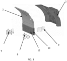
- FIG. 3 is a mudflap 1 according to an alternative example.
- the mudflap 1 allows for air 9 from the mud 7 to pass through the mudflap 1 or the bottom section 12, while particles and water 8 is deflected from the mudflap.
- the mudflap 1 or the bottom section 12 comprises a membrane 13.
- the membrane 13 may comprise multiple layers of material.
- the membrane 13 or at least part of the layers may comprise a hydrophobic material.
- the number of membrane layers will be equivalent to the desired thickness of the mudflap.
- the layers of the membrane 13 are not fully laminated or fused together, but joined at specific designated locations along the length on the edges.
- a frame or a frame structure may be used to hold the layers of the membrane together.
- the frame allows for a small distance or gap to be formed between the individual layers of the membrane, where water, slug and silt may be deflected towards the ground, while air is allowed to pass through the membrane from the frontward facing side 4 to the backward facing side 5.
- the membrane may comprise channels for guidance of slug/silt/water downwards. The channels may be formed in or between the layers.
- the membrane 13 comprises a combination of non-hydrophobic and hydrophobic layers.
- At least one liquid molecular separation membrane layer can be positioned in between at least one hydrophobic membrane layer on either side.
- the hydrophobic material of the mudflap 1, the coating layer 10 or the layers of the membrane 13 may comprise any one of polytetrafluoreten, polyurethane and polyethylene or a combination thereof.
- the perforations 11 may form through-holes, extending from the frontward facing Side 4 to the backward facing side 5.
- At least a portion of the wall of each through-hole comprises a hydrophobic material.
- said hydrophobic material may be coated onto said wall when the frontward facing side is coated with said hydrophobic material.
- the walls of the trough-holes may be formed from the mesh structure of the membrane layers, and therefore the walls may comprise the hydrophobic material of the membrane layers.
- the through-holes or perforations may further have any shape, such as circular-like holes or a mesh structure of any geometrical shape or cross-section such as triangle, rectangle, hexagon, pentagon, heptagon and an octagon or a combination thereof.
- through-holes, or perforations may have a size, or diameter, in the range of 28 to 50 mm, and be distributed across the mudflap area.
- the perforations may have a straight open area or an open cross-sectional area which is less than a predetermined area.
- the predetermined area may be based on water viscosity, the hydrophobic properties of the hydrophobic material.
- the hole size, or diameter can also be determined or influenced by the truck road conditions and the velocity. The hole size will be selected based on the above-mentioned parameters, and be based on for instance aerodynamic simulations and calculations for a specific truck or tire.
- the straight open area or an open cross-sectional area of the perforations i.e.
- the pores or through-holes will preferably be smaller than the diameter of the slug or soil mixture, i.e. the water and mud mixture from the tires that is getting sprayed on the frontward facing side 4 of the mudflap. Due to the outwards facing layer of hydrophobic material on the mudflap larger openings can be provided in the mudflap, which improves aerodynamics by allowing more air to pass through.
- the hydrophobic material thus allows for the air to pass through, but prevents or reduces the amount of slug and silt that can pass through the mudflap, and thus reduces the risk of the mudflap to become clogged. This effect is achieved due to the water repelling effect of the hydrophobic material.
- the membrane 13 or membrane layers may in one example comprise a mesh structure with perforations.
- the perforations the membrane or the membrane layers, or the mesh structure may have straight open area or an open cross-sectional area which is less than a predetermined area.
- the predetermined area may be based on water viscosity, the hydrophobic properties of the hydrophobic material and, optionally, the number of layers in the membrane.
- the size of the perforations or through-holes extending through the membrane or mudflap will be determined based on aerodynamic calculations. In one example, such calculations could be based on studies of the pressure difference across in various trucks near the tire area.
- the straight open area or an open cross-sectional area of the perforations i.e.
- the membrane 13 may comprise layers of a mesh structure comprising multiple hydrophobic layers within the mesh structure, which may be held together by a frame structure.
- the hydrophobic layers repel the water and allows the air through the membrane by allowing the slug silt to drop to the ground at the hydrophobic layers. Air continuously passes through the membrane through pores or perforations of the mesh structure. The slug will be prevented from passing through the membrane, or the holes of the mudflap slab, and drops down to ground allowing the air to pass through. This hence may reduce drag of the vehicle.
- Example 1 A mudflap 1 adapted for a vehicle, having an outer frontward facing side 4, and outer backward facing side 5, and wherein said mudflap 1 has a bottom section 12 comprising multiple perforations 11, configured to allow air 9 to pass through said bottom section 12 from said frontward facing side) to said backward facing side 5, and wherein said bottom section 12 comprises at least one hydrophobic material.
- Example 2 The mudflap 1 according to example 1, wherein said hydrophobic material is provided as a coating 10 on at least the frontward facing side 4 of said bottom section 12.
- Example 3 The mudflap 1 according to example 1, wherein the bottom section 12 further comprises a membrane 13 having multiple laminated layers, and wherein said membrane comprises said multiple perforations.
- Example 4 The mudflap 1 according to example 3, wherein said membrane 13 comprises a stack of laminated layers and wherein said stack comprises layers formed from a hydrophobic material.
- Example 5 The mudflap 1 according to example 4, wherein each layer of said membrane comprises multiple perforations.
- Example 6 The mudflap 1 according to example 4 or 5, wherein each layer of said membrane 13 comprises a mesh structure with perforations.
- Example 7 The mudflap 1 according to any one of example 1 to 6, wherein said perforations or mesh structure is defined by an open cross-sectional area which is equal to or less than a predefined area.
- Example 8 The mudflap 1 according to example 7, wherein said predefined area is based on at least one of the hydrophobic properties of the hydrophobic material, the number of layers in the membrane and the viscosity of water.
- Example 9 The mudflap 1 according to any one of examples 1 to 8, wherein said hydrophobic material or membrane or membrane layers are formed from polytetrafluoreten.
- Example 10 The mudflap 1 according to any one of examples 1 to 8, wherein said hydrophobic material or membrane or membrane layers are formed from polyurethane.
- Example 11 The mudflap 1 according to any one of examples 1 to 8, wherein said hydrophobic material or membrane or membrane layers are formed from polyethylene.
- Example 12 The mudflap (1) according to any one of examples 1 to 11, wherein said hydrophobic material or membrane or membrane layers are formed from any one of polytetrefluoreten, polyurethane and polyethylene or a combination thereof.
- Example 13 The mudflap (1) according to any one of examples 1 to 12, wherein said perforations or said mesh structure have a cross-section being any one of a circle, triangle, rectangle, hexagon, pentagon, heptagon and an octagon or a combination thereof.
- Example 14 The mudflap 1 according to any one of examples 1 to 13, wherein said perforations form through-holes.
- Example 15 The mudflap 1 according to example 14, wherein at least a wall of each through-hole comprise said hydrophobic material.
- Example 16 A fender 2 adapted for a vehicle comprising the mudflap 1 according to any one of examples 1 to 15.
- Example 17 The fender 2 according to example 16, wherein said mudflap 1 or at least a bottom portion 12 of said mudflap 1 extends below said fender 2.
- Example 18 The fender 2 according to any one of examples 16 or 17, wherein said mudflap 1 is releasably attached to said fender.
- Example 19 A vehicle comprising the mudflap 1 according to any one of examples 1 to 15, or the fender 2 according to any one of examples 16 to 18.
- Example 20 Use of a mudflap (1) according to any one of examples 1 to 15, or a fender 2 according to any one of examples 16 to 18, in a vehicle.
- Relative terms such as “below” or “above” or “upper” or “lower” or “horizontal” or “vertical” may be used herein to describe a relationship of one element to another element as illustrated in the Figures. It will be understood that these terms and those discussed above are intended to encompass different orientations of the device in addition to the orientation depicted in the Figures. It will be understood that when an element is referred to as being “connected” or “coupled” to another element, it can be directly connected or coupled to the other element, or intervening elements may be present. In contrast, when an element is referred to as being “directly connected” or “directly coupled” to another element, there are no intervening elements present.
Landscapes
- Engineering & Computer Science (AREA)
- Chemical & Material Sciences (AREA)
- Combustion & Propulsion (AREA)
- Transportation (AREA)
- Mechanical Engineering (AREA)
- Body Structure For Vehicles (AREA)
Abstract
Description
- The disclosure relates generally to a mudflap for a vehicle. In particular aspects, the disclosure relates to a mudflap having hydrophobic properties. The disclosure can be applied in all types of vehicles, including heavy-duty vehicles, such as trucks, buses, and construction equipment. Although the disclosure may be described with respect to a particular vehicle, the disclosure is not restricted to any particular vehicle.
- Mudflaps are commonly used to prevent a mixture of dirt, dust and water from the roadway to be sprayed from the tires to the rear of a vehicle such as a car or a truck. Existing antispray mudflaps are usually quite effective in meeting the soiling requirement and other regulation requirements, however, the air recirculated due to the tire movement is trapped between the tire and flap causing a drag which impacts the aerodynamic performance of vehicle. There is thus a need for an improved antispray mudflap.
- According to a first aspect of the disclosure, there is provided a mudflap adapted for a vehicle, having an outer frontward facing side, and outer backward facing side, and wherein said mudflap has a bottom section comprising multiple perforations, configured to allow air to pass through said bottom section from said frontward facing side to said backward facing side, and wherein said bottom section comprises at least one hydrophobic material. The first aspect of the disclosure may seek to provide a mudflap that reduces drag of a vehicle. A technical benefit may include a reduced energy and/or fuel consumption of the vehicle.
- In some examples, the hydrophobic material may be provided as a coating on at least the frontward facing side of said bottom section. A technical benefit may include that the coating deflects dirt and water from the mudflap.
- In some examples, the bottom section may further, or instead, comprise a membrane having multiple laminated layers, and wherein said membrane comprises said multiple perforations.
- In some examples, said membrane may comprise a stack of laminated layers, and wherein said stack may comprise layers formed from a hydrophobic material.
- In some examples, each layer of said membrane comprises multiple perforations.
- In some examples, each layer of said membrane comprises a mesh structure with perforations.
- In some examples, said perforations or mesh structure may be defined by an open cross-sectional area which is equal to or less than a predefined area.
- In some examples, said predefined area may be based on at least one of the hydrophobic properties of the hydrophobic material, the number of layers in the membrane and the viscosity of water. The technical benefit may include that the membrane will thus not allow water to pass through, while air passes the membrane and hence reduces drag of the vehicle.
- In some examples, the hydrophobic material or membrane or membrane layers may be formed from polytetrafluoreten.
- In some examples, the hydrophobic material or membrane or membrane layers may be formed from polyurethane.
- In some examples, the hydrophobic material or membrane or membrane layers may be formed from polyethylene.
- In some examples, the hydrophobic material or membrane or membrane layers are formed from any one of polytetrefluoreten, polyurethane and polyethylene or a combination thereof.
- In some examples, said perforations or said mesh structure have a cross-section which may be any one of a circle, triangle, rectangle, hexagon, pentagon, heptagon and an octagon or a combination thereof.
- In some examples, the perforations form through-holes.
- In some examples, at least a wall of each through-hole comprises said hydrophobic material. The technical benefit may include that water and dirt more easily can pass through the through-hole, thus reducing the risk of the trough-hole being clogged.
- According to a second aspect of the disclosure, there is provided a fender adapted for a vehicle comprising the mudflap according to the first aspect. The second aspect of the disclosure may seek to a fender having reduced drag, and hence reduced fuel and/or energy consumption of the vehicle. Further to this,
- In some examples, said mudflap or at least a bottom section of said mudflap extends below said fender.
- In some examples, said mudflap may be releasably attached to said fender. This may allow for the technical benefit that the mudflap may be retro-fitted or replaced easily of the mudflap is releasably attached to the fender.
- According to a third aspect, there is provided a vehicle comprising the mudflap according to the first aspect, or the fender according to the second aspect. The technical benefit may include that the vehicle experiences less drag, and thus may have a reduced energy and/or fuel consumption.
- According to a fourth aspect, there is provided the use of a mudflap according to the first aspect, or a fender according to the second aspect, in a vehicle.
- The above aspects, accompanying claims, and/or examples disclosed herein above and later below may be suitably combined with each other as would be apparent to anyone of ordinary skill in the art.
- Additional features and advantages are disclosed in the following description, claims, and drawings, and in part will be readily apparent therefrom to those skilled in the art or recognized by practicing the disclosure as described herein.
- With reference to the appended drawings, below follows a more detailed description of aspects of the disclosure cited as examples.
-
FIG. 1 is an exemplary mudflap according to one example. -
FIG. 2 is an exemplary mudflap in an exploded view according to one example. -
FIG. 2 is an exemplary mudflap in an exploded view according to another example. - Aspects set forth below represent the necessary information to enable those skilled in the art to practice the disclosure.
- With existing antispray mudflaps air which is recirculated between due to the tire movement is trapped between the tire and flap causing a drag which impacts the aerodynamic performance of a vehicle. The inventive mudflap for a vehicle, which is coated or at least partly made out of a hydrophobic material may reduce mud or dirt sticking to the mudflap, and allow for air to pass through perforations in the mudflap. This will reduce drag of the vehicle and in turn reduce energy/fuel consumption. The combination of having a mudflap with perforations and it being coated or at least partly made of a hydrophobic material will reduce risk of dirt and/or mud to clog the perforations.
-
FIG. 1 is anexemplary mudflap 1 arranged on afender 2 of a vehicle according to one example. Thefender 2 is arranged behind awheel 3. The mudflap has an outer frontward facingside 4, and an outer backward facingside 5. The frontward facingside 4 is thus facing thewheel 3. When thewheel 3 contacts aroad surface 6mud 7, i.e. particles mixed with water and air, that splashes from theroad surface 6 and hits the frontward facingside 4 of the mudflap. According to the inventive concept the mudflap allows for air (A) 9 to pass through themudflap 1, through perforations or through-holes arranged in at least a portion or section of the mudflap, and deflects water andparticles 8 back onto the road surface. Themudflap 1 or at least a bottom portion orsection 12 of themudflap 1 may extend below saidfender 2. Themudflap 1 may be releasably attached to thefender 2. This may allow for the mudflap to be removed and exchanged for a new mudflap if it has for instance been worn out or damaged. -
FIG. 2 is anexemplary mudflap 1 in an exploded view. Themudflap 1 or abottom section 12 thereof, may be provided with acoating layer 10 on the frontward facingside 4. Thisexemplary mudflap 1 is also illustrated in the previousFIG. 1 . Thecoating layer 10 may be made from a hydrophobic material. The hydrophobic material may at least partially deflect water and dirt (slug and soil) that hits the frontward facing surface of the mudflap. The hydrophobic material thus deflects water andparticles 8. Themudflap 1 may further comprise a body or slab of a rigid or flexible material. Themudflap 1, or the mudflap slab, may further be provided with perforations or through-holes 11 that allow forair 9 to pass through. These perforations oropenings 11 form pores or through-holes, which extends from the frontward facingside 4 to the backward facingside 5. The mudflap according to this example may be formed by providing a mudflap, such as for instance a slab a rigid or flexible material, e.g. rubber, with perforations or through-holes, and then apply a hydrophobic material as a coating on the frontward facing side. According to one example, at least a part of the walls of the trough-holes may further comprise a hydrophobic material, or be provided with a hydrophobic material -
FIG. 3 is amudflap 1 according to an alternative example. According to the inventive concept themudflap 1 allows forair 9 from themud 7 to pass through themudflap 1 or thebottom section 12, while particles andwater 8 is deflected from the mudflap. In the alternative example themudflap 1 or thebottom section 12 comprises amembrane 13. Themembrane 13 may comprise multiple layers of material. Themembrane 13 or at least part of the layers may comprise a hydrophobic material. The number of membrane layers will be equivalent to the desired thickness of the mudflap. According to one example, the layers of themembrane 13 are not fully laminated or fused together, but joined at specific designated locations along the length on the edges. - In one example, a frame or a frame structure may be used to hold the layers of the membrane together. One advantage may be that the frame allows for a small distance or gap to be formed between the individual layers of the membrane, where water, slug and silt may be deflected towards the ground, while air is allowed to pass through the membrane from the frontward facing
side 4 to the backward facingside 5. Additionally or alternatively the membrane may comprise channels for guidance of slug/silt/water downwards. The channels may be formed in or between the layers. - According to one example the
membrane 13 comprises a combination of non-hydrophobic and hydrophobic layers. - In one example, at least one liquid molecular separation membrane layer can be positioned in between at least one hydrophobic membrane layer on either side.
- The hydrophobic material of the
mudflap 1, thecoating layer 10 or the layers of themembrane 13 may comprise any one of polytetrafluoreten, polyurethane and polyethylene or a combination thereof. - The
perforations 11 may form through-holes, extending from the frontward facingSide 4 to the backward facingside 5. - According to one example at least a portion of the wall of each through-hole comprises a hydrophobic material. According to one alternative said hydrophobic material may be coated onto said wall when the frontward facing side is coated with said hydrophobic material. According to another alternative the walls of the trough-holes may be formed from the mesh structure of the membrane layers, and therefore the walls may comprise the hydrophobic material of the membrane layers.
- The through-holes or perforations may further have any shape, such as circular-like holes or a mesh structure of any geometrical shape or cross-section such as triangle, rectangle, hexagon, pentagon, heptagon and an octagon or a combination thereof.
- According to one example, as illustrated in
FIG. 1 through-holes, or perforations, may have a size, or diameter, in the range of 28 to 50 mm, and be distributed across the mudflap area. The perforations may have a straight open area or an open cross-sectional area which is less than a predetermined area. The predetermined area may be based on water viscosity, the hydrophobic properties of the hydrophobic material. The hole size, or diameter, can also be determined or influenced by the truck road conditions and the velocity. The hole size will be selected based on the above-mentioned parameters, and be based on for instance aerodynamic simulations and calculations for a specific truck or tire. The straight open area or an open cross-sectional area of the perforations, i.e. the pores or through-holes, will preferably be smaller than the diameter of the slug or soil mixture, i.e. the water and mud mixture from the tires that is getting sprayed on the frontward facingside 4 of the mudflap. Due to the outwards facing layer of hydrophobic material on the mudflap larger openings can be provided in the mudflap, which improves aerodynamics by allowing more air to pass through. The hydrophobic material thus allows for the air to pass through, but prevents or reduces the amount of slug and silt that can pass through the mudflap, and thus reduces the risk of the mudflap to become clogged. This effect is achieved due to the water repelling effect of the hydrophobic material. This affects also the surface tension of the slug and silt typically containing water, by creating larger droplets which, and by this reducing the risk of slug and silt to enter the perforations. Larger and heavier droplets of slug and silt are further more prone to run downwards towards the ground, due to gravitational forces. - The
membrane 13 or membrane layers may in one example comprise a mesh structure with perforations. The perforations the membrane or the membrane layers, or the mesh structure, may have straight open area or an open cross-sectional area which is less than a predetermined area. The predetermined area may be based on water viscosity, the hydrophobic properties of the hydrophobic material and, optionally, the number of layers in the membrane. The size of the perforations or through-holes extending through the membrane or mudflap will be determined based on aerodynamic calculations. In one example, such calculations could be based on studies of the pressure difference across in various trucks near the tire area. The straight open area or an open cross-sectional area of the perforations, i.e. the pores or through-holes, will preferably be smaller than the diameter of the slug or soil mixture, i.e. the water and mud mixture from the tires that is getting sprayed on the frontward facing side of the mudflap ormembrane 13. Themembrane 13 may comprise layers of a mesh structure comprising multiple hydrophobic layers within the mesh structure, which may be held together by a frame structure. The hydrophobic layers repel the water and allows the air through the membrane by allowing the slug silt to drop to the ground at the hydrophobic layers. Air continuously passes through the membrane through pores or perforations of the mesh structure. The slug will be prevented from passing through the membrane, or the holes of the mudflap slab, and drops down to ground allowing the air to pass through. This hence may reduce drag of the vehicle. - In the following the inventive concept will be described by way of examples.
- Example 1: A
mudflap 1 adapted for a vehicle, having an outer frontward facingside 4, and outer backward facingside 5, and wherein saidmudflap 1 has abottom section 12 comprisingmultiple perforations 11, configured to allowair 9 to pass through saidbottom section 12 from said frontward facing side) to said backward facingside 5, and wherein saidbottom section 12 comprises at least one hydrophobic material. - Example 2: The
mudflap 1 according to example 1, wherein said hydrophobic material is provided as acoating 10 on at least the frontward facingside 4 of saidbottom section 12. - Example 3: The
mudflap 1 according to example 1, wherein thebottom section 12 further comprises amembrane 13 having multiple laminated layers, and wherein said membrane comprises said multiple perforations. - Example 4: The
mudflap 1 according to example 3, wherein saidmembrane 13 comprises a stack of laminated layers and wherein said stack comprises layers formed from a hydrophobic material. - Example 5: The
mudflap 1 according to example 4, wherein each layer of said membrane comprises multiple perforations. - Example 6: The
mudflap 1 according to example 4 or 5, wherein each layer of saidmembrane 13 comprises a mesh structure with perforations. - Example 7: The
mudflap 1 according to any one of example 1 to 6, wherein said perforations or mesh structure is defined by an open cross-sectional area which is equal to or less than a predefined area. - Example 8: The
mudflap 1 according to example 7, wherein said predefined area is based on at least one of the hydrophobic properties of the hydrophobic material, the number of layers in the membrane and the viscosity of water. - Example 9: The
mudflap 1 according to any one of examples 1 to 8, wherein said hydrophobic material or membrane or membrane layers are formed from polytetrafluoreten. - Example 10: The
mudflap 1 according to any one of examples 1 to 8, wherein said hydrophobic material or membrane or membrane layers are formed from polyurethane. - Example 11: The
mudflap 1 according to any one of examples 1 to 8, wherein said hydrophobic material or membrane or membrane layers are formed from polyethylene. - Example 12: The mudflap (1) according to any one of examples 1 to 11, wherein said hydrophobic material or membrane or membrane layers are formed from any one of polytetrefluoreten, polyurethane and polyethylene or a combination thereof.
- Example 13: The mudflap (1) according to any one of examples 1 to 12, wherein said perforations or said mesh structure have a cross-section being any one of a circle, triangle, rectangle, hexagon, pentagon, heptagon and an octagon or a combination thereof.
- Example 14: The
mudflap 1 according to any one of examples 1 to 13, wherein said perforations form through-holes. - Example 15: The
mudflap 1 according to example 14, wherein at least a wall of each through-hole comprise said hydrophobic material. - Example 16: A
fender 2 adapted for a vehicle comprising themudflap 1 according to any one of examples 1 to 15. - Example 17: The
fender 2 according to example 16, wherein saidmudflap 1 or at least abottom portion 12 of saidmudflap 1 extends below saidfender 2. - Example 18: The
fender 2 according to any one of examples 16 or 17, wherein saidmudflap 1 is releasably attached to said fender. - Example 19: A vehicle comprising the
mudflap 1 according to any one of examples 1 to 15, or thefender 2 according to any one of examples 16 to 18. - Example 20: Use of a mudflap (1) according to any one of examples 1 to 15, or a
fender 2 according to any one of examples 16 to 18, in a vehicle. - The terminology used herein is for the purpose of describing particular aspects only and is not intended to be limiting of the disclosure. As used herein, the singular forms "a," "an," and "the" are intended to include the plural forms as well, unless the context clearly indicates otherwise. As used herein, the term "and/or" includes any and all combinations of one or more of the associated listed items. It will be further understood that the terms "comprises," "comprising," "includes," and/or "including" when used herein specify the presence of stated features, integers, steps, operations, elements, and/or components, but do not preclude the presence or addition of one or more other features, integers, steps, operations, elements, components, and/or groups thereof.
- It will be understood that, although the terms first, second, etc., may be used herein to describe various elements, these elements should not be limited by these terms. These terms are only used to distinguish one element from another. For example, a first element could be termed a second element, and, similarly, a second element could be termed a first element without departing from the scope of the present disclosure.
- Relative terms such as "below" or "above" or "upper" or "lower" or "horizontal" or "vertical" may be used herein to describe a relationship of one element to another element as illustrated in the Figures. It will be understood that these terms and those discussed above are intended to encompass different orientations of the device in addition to the orientation depicted in the Figures. It will be understood that when an element is referred to as being "connected" or "coupled" to another element, it can be directly connected or coupled to the other element, or intervening elements may be present. In contrast, when an element is referred to as being "directly connected" or "directly coupled" to another element, there are no intervening elements present.
- Unless otherwise defined, all terms (including technical and scientific terms) used herein have the same meaning as commonly understood by one of ordinary skill in the art to which this disclosure belongs. It will be further understood that terms used herein should be interpreted as having a meaning consistent with their meaning in the context of this specification and the relevant art and will not be interpreted in an idealized or overly formal sense unless expressly so defined herein.
- It is to be understood that the present disclosure is not limited to the aspects described above and illustrated in the drawings; rather, the skilled person will recognize that many changes and modifications may be made within the scope of the present disclosure and appended claims. In the drawings and specification, there have been disclosed aspects for purposes of illustration only and not for purposes of limitation, the scope of the inventive concepts being set forth in the following claims.
Claims (15)
- A mudflap (1) adapted for a vehicle, having an outer frontward facing side (4), and outer backward facing side (5), and wherein said mudflap (1) has a bottom section (12) comprising multiple perforations (11), configured to allow air (9) to pass through said bottom section (12) from said frontward facing side (4) to said backward facing side (5), and wherein said bottom section (12) comprises at least one hydrophobic material.
- The mudflap (1) according to claim 1, wherein said hydrophobic material is provided as a coating (10) on at least the frontward facing side (4) of said bottom section (12).
- The mudflap (1) according to claim 1, wherein the bottom section (12) further comprises a membrane (13) having multiple laminated layers, and wherein said membrane comprises said multiple perforations.
- The mudflap (1) according to claim 3, wherein said membrane (13) comprises a stack of laminated layers and wherein said stack comprises layers formed from a hydrophobic material.
- The mudflap (1) according to claim 4, wherein each layer of said membrane comprises multiple perforations or wherein each layer of said membrane comprises a mesh structure with perforations.
- The mudflap (1) according to any one of claims 1 to 5, wherein said perforations or mesh structure is defined by an open cross-sectional area which is equal to or less than a predefined area, and wherein said predefined area is based on at least one of the hydrophobic properties of the hydrophobic material, the number of layers in the membrane and the viscosity of water.
- The mudflap (1) according to any one of claims 1 to 6, wherein said hydrophobic material or membrane or membrane layers are formed from any one of polytetrefluoreten, polyurethane and polyethylene, or a combination thereof.
- The mudflap (1) according to any one of claims 1 to 7, wherein said perforations or said mesh structure have a cross-section being any one of a circle, triangle, rectangle, hexagon, pentagon, heptagon and an octagon or a combination thereof.
- The mudflap (1) according to any one of claims 1 to 8, wherein said perforations form through-holes.
- The mudflap (1) according to claim 9, wherein at least a wall of each through-hole comprise said hydrophobic material.
- A fender (2) adapted for a vehicle comprising the mudflap (1) according to any one of claims 1 to 10.
- The fender (2) according to claim 11, wherein said mudflap (1) or at least a bottom section (12) of said mudflap (1) extends below said fender (2).
- The fender (2) according to any one of claims 11 or 12, wherein said mudflap (1) is releasably attached to said fender.
- A vehicle comprising the mudflap (1) according to any one of claims 1 to 10, or the fender (2) according to any one of claims 1 10to 13.
- Use of a mudflap (1) according to any one of claim 1 to 10, or a fender (2) according to any one of claims 11 to 13, in a vehicle.
Priority Applications (1)
| Application Number | Priority Date | Filing Date | Title |
|---|---|---|---|
| EP23157989.7A EP4420961A1 (en) | 2023-02-22 | 2023-02-22 | Mudflap with hydrophobic properties |
Applications Claiming Priority (1)
| Application Number | Priority Date | Filing Date | Title |
|---|---|---|---|
| EP23157989.7A EP4420961A1 (en) | 2023-02-22 | 2023-02-22 | Mudflap with hydrophobic properties |
Publications (1)
| Publication Number | Publication Date |
|---|---|
| EP4420961A1 true EP4420961A1 (en) | 2024-08-28 |
Family
ID=85328842
Family Applications (1)
| Application Number | Title | Priority Date | Filing Date |
|---|---|---|---|
| EP23157989.7A Pending EP4420961A1 (en) | 2023-02-22 | 2023-02-22 | Mudflap with hydrophobic properties |
Country Status (1)
| Country | Link |
|---|---|
| EP (1) | EP4420961A1 (en) |
Citations (2)
| Publication number | Priority date | Publication date | Assignee | Title |
|---|---|---|---|---|
| US9221390B1 (en) * | 2015-02-11 | 2015-12-29 | Globetech Manufacturing | Aerodynamic mudflap with lighting element |
| EP4071032A1 (en) * | 2021-04-08 | 2022-10-12 | Volvo Truck Corporation | Mudflap with aerodynamic improvement |
-
2023
- 2023-02-22 EP EP23157989.7A patent/EP4420961A1/en active Pending
Patent Citations (2)
| Publication number | Priority date | Publication date | Assignee | Title |
|---|---|---|---|---|
| US9221390B1 (en) * | 2015-02-11 | 2015-12-29 | Globetech Manufacturing | Aerodynamic mudflap with lighting element |
| EP4071032A1 (en) * | 2021-04-08 | 2022-10-12 | Volvo Truck Corporation | Mudflap with aerodynamic improvement |
Similar Documents
| Publication | Publication Date | Title |
|---|---|---|
| CA1178631A (en) | Spray controlling system and splash guard for automotive vehicles | |
| US5375882A (en) | Mist suppressant panels for a vehicle and a method of suppressing mist | |
| US9868479B2 (en) | Configurable rear underbody aerodynamic diffuser | |
| AU2021261852B2 (en) | Aerodynamic mud flap | |
| DE102016115981B4 (en) | Vehicle with an active aerodynamic device for the underside of the vehicle | |
| US5564750A (en) | Energy saving and heat venting vehicle mud flap | |
| US8136867B2 (en) | Aerodynamic structure for vehicle | |
| WO2008052036A2 (en) | Spray suppression device for vehicles | |
| GB2132148A (en) | Vehicle spray inhibitor | |
| EP0134156A1 (en) | Spray suppressant mud flap | |
| US20030011188A1 (en) | Mud Flap | |
| EP4420961A1 (en) | Mudflap with hydrophobic properties | |
| CA1156293A (en) | Trailer undercarriage fairings | |
| US4585243A (en) | Spray controlling vehicle splash guard | |
| US4325563A (en) | Vehicle spray reduction | |
| JPH08258511A (en) | Traveling body with lug | |
| WO2019226214A1 (en) | Curved quarter fender rock guard | |
| WO2018041890A1 (en) | Apparatus and method for reducing soiling on a vehicle | |
| US7278606B2 (en) | Helicopter having a fusilage section and a tail section coupled thereto | |
| EP0139345A1 (en) | Spray suppression on motor vehicles | |
| JP2011132914A (en) | Air intake duct | |
| GB2209720A (en) | Vehicle anti-spray attachment | |
| US20260125116A1 (en) | Heavy-Vehicle Mud Flap | |
| DE19625739A1 (en) | Airflow deflector for reducing air flow resistance and spray water of vehicle, esp. commercial vehicle - is fitted on rear end and serves to guide air flow between undersurface and road so that flow can be reversed | |
| SE524433C2 (en) | Wear surface construction in a hub deck |
Legal Events
| Date | Code | Title | Description |
|---|---|---|---|
| PUAI | Public reference made under article 153(3) epc to a published international application that has entered the european phase |
Free format text: ORIGINAL CODE: 0009012 |
|
| STAA | Information on the status of an ep patent application or granted ep patent |
Free format text: STATUS: THE APPLICATION HAS BEEN PUBLISHED |
|
| AK | Designated contracting states |
Kind code of ref document: A1 Designated state(s): AL AT BE BG CH CY CZ DE DK EE ES FI FR GB GR HR HU IE IS IT LI LT LU LV MC ME MK MT NL NO PL PT RO RS SE SI SK SM TR |
|
| STAA | Information on the status of an ep patent application or granted ep patent |
Free format text: STATUS: REQUEST FOR EXAMINATION WAS MADE |
|
| 17P | Request for examination filed |
Effective date: 20250207 |
|
| GRAP | Despatch of communication of intention to grant a patent |
Free format text: ORIGINAL CODE: EPIDOSNIGR1 |
|
| STAA | Information on the status of an ep patent application or granted ep patent |
Free format text: STATUS: GRANT OF PATENT IS INTENDED |
|
| INTG | Intention to grant announced |
Effective date: 20260303 |