EP4420954A1 - Armrest mounting units, handcarts and seat components - Google Patents
Armrest mounting units, handcarts and seat components Download PDFInfo
- Publication number
- EP4420954A1 EP4420954A1 EP24159292.2A EP24159292A EP4420954A1 EP 4420954 A1 EP4420954 A1 EP 4420954A1 EP 24159292 A EP24159292 A EP 24159292A EP 4420954 A1 EP4420954 A1 EP 4420954A1
- Authority
- EP
- European Patent Office
- Prior art keywords
- magnetic
- magnetic member
- disposed
- unlocking
- engaging
- Prior art date
- Legal status (The legal status is an assumption and is not a legal conclusion. Google has not performed a legal analysis and makes no representation as to the accuracy of the status listed.)
- Pending
Links
Images











Classifications
-
- B—PERFORMING OPERATIONS; TRANSPORTING
- B62—LAND VEHICLES FOR TRAVELLING OTHERWISE THAN ON RAILS
- B62B—HAND-PROPELLED VEHICLES, e.g. HAND CARTS OR PERAMBULATORS; SLEDGES
- B62B9/00—Accessories or details specially adapted for children's carriages or perambulators
- B62B9/10—Perambulator bodies; Equipment therefor
- B62B9/102—Perambulator bodies; Equipment therefor characterized by details of the seat
-
- B—PERFORMING OPERATIONS; TRANSPORTING
- B62—LAND VEHICLES FOR TRAVELLING OTHERWISE THAN ON RAILS
- B62B—HAND-PROPELLED VEHICLES, e.g. HAND CARTS OR PERAMBULATORS; SLEDGES
- B62B9/00—Accessories or details specially adapted for children's carriages or perambulators
- B62B9/26—Securing devices for bags or toys ; Arrangements of racks, bins, trays or other devices for transporting articles
-
- B—PERFORMING OPERATIONS; TRANSPORTING
- B62—LAND VEHICLES FOR TRAVELLING OTHERWISE THAN ON RAILS
- B62B—HAND-PROPELLED VEHICLES, e.g. HAND CARTS OR PERAMBULATORS; SLEDGES
- B62B9/00—Accessories or details specially adapted for children's carriages or perambulators
- B62B9/10—Perambulator bodies; Equipment therefor
-
- A—HUMAN NECESSITIES
- A47—FURNITURE; DOMESTIC ARTICLES OR APPLIANCES; COFFEE MILLS; SPICE MILLS; SUCTION CLEANERS IN GENERAL
- A47C—CHAIRS; SOFAS; BEDS
- A47C7/00—Parts, details, or accessories of chairs or stools
- A47C7/54—Supports for the arms
- A47C7/546—Supports for the arms of detachable type
-
- B—PERFORMING OPERATIONS; TRANSPORTING
- B62—LAND VEHICLES FOR TRAVELLING OTHERWISE THAN ON RAILS
- B62B—HAND-PROPELLED VEHICLES, e.g. HAND CARTS OR PERAMBULATORS; SLEDGES
- B62B7/00—Carriages for children; Perambulators, e.g. dolls' perambulators
-
- B—PERFORMING OPERATIONS; TRANSPORTING
- B62—LAND VEHICLES FOR TRAVELLING OTHERWISE THAN ON RAILS
- B62B—HAND-PROPELLED VEHICLES, e.g. HAND CARTS OR PERAMBULATORS; SLEDGES
- B62B7/00—Carriages for children; Perambulators, e.g. dolls' perambulators
- B62B7/006—Carriages supporting a rigid seat
-
- B—PERFORMING OPERATIONS; TRANSPORTING
- B62—LAND VEHICLES FOR TRAVELLING OTHERWISE THAN ON RAILS
- B62B—HAND-PROPELLED VEHICLES, e.g. HAND CARTS OR PERAMBULATORS; SLEDGES
- B62B7/00—Carriages for children; Perambulators, e.g. dolls' perambulators
- B62B7/04—Carriages for children; Perambulators, e.g. dolls' perambulators having more than one wheel axis; Steering devices therefor
-
- B—PERFORMING OPERATIONS; TRANSPORTING
- B62—LAND VEHICLES FOR TRAVELLING OTHERWISE THAN ON RAILS
- B62B—HAND-PROPELLED VEHICLES, e.g. HAND CARTS OR PERAMBULATORS; SLEDGES
- B62B9/00—Accessories or details specially adapted for children's carriages or perambulators
- B62B9/10—Perambulator bodies; Equipment therefor
- B62B9/12—Perambulator bodies; Equipment therefor involving parts that are adjustable, attachable or detachable
-
- B—PERFORMING OPERATIONS; TRANSPORTING
- B62—LAND VEHICLES FOR TRAVELLING OTHERWISE THAN ON RAILS
- B62B—HAND-PROPELLED VEHICLES, e.g. HAND CARTS OR PERAMBULATORS; SLEDGES
- B62B9/00—Accessories or details specially adapted for children's carriages or perambulators
- B62B9/24—Safety guards for children, e.g. harness
Definitions
- the present application relates to the technical field of carries, and in particular, to an armrest mounting unit, a handcart, and a seat assembly.
- an armrest body is detachably connected to a frame.
- accurate positioning is required to lock the armrest body and the frame.
- a locked force between the armrest body and the frame also needs to be overcome, and after the armrest body is unlocked, the armrest cannot be released automatically, and thus additional force is required to remove the armrest body, resulting in that the use process is very inconvenient and the armrest body cannot be quickly mounted and removed.
- an armrest mounting unit a handcart, and a seat assembly is provided.
- An armrest mounting unit includes: a fixed base; a connecting base; a first magnetic member fixed on one of the fixed base and the connecting base; and a locking mechanism disposed on the other one of the fixed base and the connecting base.
- the locking mechanism under the action of the magnetic force (including attractive force and/or repulsive force) formed between the first magnetic member and the locking mechanism, the locking mechanism can be switched between the locked state where the fixed base is fixed onto the connecting base and the unlocked state where the fixed base is separated from the connecting base.
- the fixed base and the connecting base are respectively mounted on, for example, the armrest body and the frame, the armrest body can be quickly mounted on and removed from the frame, which is convenient to use.
- the locking mechanism is disposed on the connecting base, and includes: an unlocking member operable to move between a first locked position and a first unlocked position; an engaging member disposed on the connecting base; and a second magnetic member movably disposed on the connecting base, and forms a magnetic action with the first magnetic member.
- the locking mechanism further includes a rotatable member rotatably disposed at the connecting base and having a first rotation position and a second rotation position.
- the second magnetic member is disposed on the rotatable member.
- the second magnetic member includes two ends serving as a first magnetic pole and a second magnetic pole respectively.
- the first magnetic pole and the first magnetic member face and attract each other.
- the second magnetic pole and the first magnetic member face and repel each other.
- the unlocking member drives the rotatable member to rotate to the first rotation position.
- the unlocking member drives the rotatable member to rotate to the second rotation position.
- the locking mechanism further includes a connecting shaft fixed to the connecting base.
- the rotatable member is sleeved on the connecting shaft and is rotable around the connecting shaft.
- the unlocking member is provided with a sawtooth part.
- the rotatable member is provided with a gear part engageable with the unlocking member.
- the unlocking member drives the rotatable member to rotate through a cooperation of the sawtooth part and the gear part.
- the unlocking member is movable between the first locked position and the first unlocked position.
- the unlocking member is provided with a sawtooth part.
- the sawtooth part is disposed in a moving direction of the unlocking member.
- the rotatable member is provided with a gear part engageable with the unlocking member.
- the gear part protrudes from a side surface of the rotatable member.
- the sawtooth part is engaged with the gear part.
- the second magnetic member is fixedly connected to the unlocking member.
- the second magnetic member faces and forms a magnetic action with the first magnetic member.
- the second magnetic member is staggered from the first magnetic member to remove the magnetic action.
- the second magnetic member is a permanent magnet; or the second magnetic member is made of a ferromagnetic material.
- the locking mechanism further includes a third magnetic member.
- the second magnetic member and the third magnetic member are spaced apart from each other, and are fixedly connected to the unlocking member.
- the second magnetic member faces and attracts the first magnetic member.
- the third magnetic member faces and repels the first magnetic member.
- the locking mechanism further includes a moving member.
- the second magnetic member and the third magnetic member are spaced apart on the moving member.
- the moving member is fixed to the unlocking member.
- the engaging member includes an abutting portion.
- the unlocking member includes a pushing part. During a movement of the unlocking member from the first locked position to the first unlocked position, the pushing part pushes against the abutting portion so that the engaging member is disengaged from the fixed base.
- the engaging member includes an engaging arm.
- the fixed base includes an engaging groove.
- the engaging arm is engaged with the engaging groove.
- the engaging arm is disengaged from the engaging groove.
- the engaging member includes an abutting portion.
- the unlocking member includes a pushing part. During a movement of the unlocking member from the first locked position to the first unlocked position, the pushing part pushes against the abutting portion so that the engaging member is elastically deformed to be disengaged from the fixed base.
- the engaging member includes an engaging arm.
- the abutting portion is disposed at the engaging arm.
- the fixed base includes an engaging groove.
- the pushing part includes a pushing inclined surface. During the movement of the unlocking member from the first locked position to the first unlocked position, the pushing inclined surface pushes against the abutting portion, so that the engaging arm is elastically deformed in a direction away from the engaging groove.
- the engaging member further includes a fixing part connected to the engaging arm.
- the fixing part is fixed to the connecting base.
- the unlocking member includes an operating part.
- the operating part is operable so that the unlocking member moves between the first locked position and the first unlocked position.
- the locking mechanism further includes an operating member.
- the unlocking member includes an operating part.
- the operating member is connected to or abuts against the operating part.
- the operating member is operable to drive the unlocking member to move between the first locked position and the first unlocked position through the operating part.
- the engaging member includes two engaging arms facing each other and a fixing part connected between the two engaging arms.
- the fixing part is fixed on the connecting base.
- the fixed base includes an annular engaging groove.
- the fixed base is located between the two engaging arms.
- Each of the two engaging arms is provided with an abutting portion.
- the unlocking member is provided with two pushing parts facing each other. When the unlocking member is in the first locked position, the two engaging arms are engaged with the engaging groove. During a movement of the unlocking member from the first locked position to the first unlocked position, the two pushing parts push against two abutting portions respectively so that the two engaging arms are elastically deformed in a direction away from each other to be disengaged from the engaging groove.
- the unlocking member further includes two operating parts respectively fixedly connected to the two pushing parts.
- the two operating parts are operable to drive the two pushing parts to move.
- the unlocking member further includes an operating part connected to the two pushing parts.
- the operating part is operable to drive the two pushing parts to move.
- the locking mechanism further includes a reset member disposed between the unlocking member and the connecting base.
- the reset member is adapted to bias the unlocking member to move toward the first locked position.
- the connecting base includes a first cover and a second cover.
- the first cover and the second cover enclose a receiving space.
- the engaging member, the second magnetic member, and at least part of the unlocking member is disposed in the receiving space.
- the fixed base includes a first coupling portion; the connecting base includes a second coupling portion.
- the connecting base When the connecting base is engaged with and locked with the fixed base, the second coupling portion is sleeved outside the first coupling portion.
- a handcart includes: a frame; an armrest body; and an armrest mounting unit as described on any one of the above embodiments.
- the fixed base is disposed on one of the frame and armrest body.
- the connecting base is disposed on the other one of the frame and armrest body.
- the armrest body is detachably mounted on the frame through the armrest mounting unit.
- two armrest mounting units are provided; and two ends of the armrest body are detachably connected to two sides of the frame through the two armrest mounting units respectively.
- the frame includes a seat assembly; the handcart further includes: a restraint belt disposed on the seat assembly and having a restraining position and a non-restraining position; a locking buckle assembly connected to the restraint belt and having a locked state and an unlocked state; and a positioning mechanism disposed between the restraint belt and the seat assembly.
- the locking buckle assembly When the locking buckle assembly is in the locked state, the locking buckle assembly is connectable to the restraint belt to keep the restraint belt in the restraining position.
- the positioning mechanism keeps the restraint belt in the non-restraining position.
- the positioning mechanism includes a fourth magnetic member disposed on the seat assembly and a fifth magnetic member disposed on the restraint belt.
- the fourth magnetic member and the fifth magnetic member are capable of attracting each other to keep the restraint belt in the non-restraining position.
- the positioning mechanism further includes a protective piece sleeved outside the restraint belt and a fourth magnetic member disposed on the seat assembly or a fifth magnetic member disposed on the protective piece.
- An end of the restraint belt is capable of extending out of the protective piece.
- the positioning mechanism includes a protective piece sleeved outside the restraint belt and a flexible resilient member disposed in the protective piece.
- the flexible resilient member always moves the restraint belt toward the non-restraining position.
- the flexible resilient member is made of a polyvinyl chloride material, or metal material.
- the seat assembly includes a seat part configured to carry an occupant.
- the seat part includes a first side facing away from the occupant and a second side facing the occupant.
- the seat part is provided with a through hole.
- the protective piece includes a first piece part and a second piece part that are connected to each other. A maximum width of the first piece part is greater than a hole diameter of the through hole. An end of the second piece part connected to the first piece part has a width less than or equal to the hole diameter of the through hole.
- the protective piece extends through the through hole.
- the first piece part is located on the first side of the seat part, and the second piece part is located on the second side of the seat part.
- the flexible resilient member extends from the first piece part to the second piece part.
- the flexible resilient member includes a first elastic part and a second elastic part connected to each other.
- the first elastic part is located in the first piece part
- the second elastic part is located in the second piece part.
- a maximum width of the first elastic part is greater than a maximum width of the second elastic part.
- the positioning mechanism further includes a fourth magnetic member disposed on the seat assembly and a fifth magnetic member disposed on the protective piece.
- the fourth magnetic member and the fifth magnetic member are capable of attracting each other to keep the restraint belt in the non-restraining position.
- the positioning mechanism further includes a fourth magnetic member disposed on the seat assembly.
- the flexible resilient member is made of a ferromagnetic material.
- the flexible resilient member always moves the restraint belt toward the non-restraining position.
- the fourth magnetic member and the flexible resilient member are capable of attracting each other to keep the restraint belt in the non-restraining position.
- the protective piece includes an opening.
- the flexible resilient member is removable from the protective piece through the opening.
- a pocket is disposed on the protective piece, and the flexible resilient member is removably inserted into the pocket.
- the flexible resilient member is a fishbone spring.
- the fishbone spring is fixed in the protective piece by sewing.
- the protective piece is filled with a cushioning material.
- the flexible resilient member is located between the cushioning material and the restraint belt.
- the positioning mechanism includes a protective piece sleeved outside the restraint belt.
- the protective piece is made of a flexible rubber material.
- the restraint belt includes a crotch belt adapted to be disposed between two thighs of an occupant.
- the positioning mechanism is disposed between the crotch belt and the seat assembly.
- a seat assembly includes: a seat part; a restraint belt disposed on the seat part and having a restraining position and a non-restraining position; a locking buckle assembly connected to the restraint belt and having a locked state and an unlocked state; and a positioning mechanism disposed between the restraint belt and the seat part.
- the locking buckle assembly When the locking buckle assembly is in the locked state, the locking buckle assembly is connectable to the restraint belt to keep the restraint belt in the restraining position.
- the positioning mechanism keeps the restraint belt in the non-restraining position.
- the positioning mechanism includes a fourth magnetic member disposed on the seat part and a fifth magnetic member disposed on the restraint belt.
- the fourth magnetic member and the fifth magnetic member are capable of attracting each other to keep the restraint belt in the non-restraining position.
- the positioning mechanism further includes: a protective piece sleeved outside the restraint belt; and a fourth magnetic member disposed on the seat part and a fifth magnetic member disposed on the protective piece.
- An end of the restraint belt is capable of extending out of the protective piece.
- the positioning mechanism includes a protective piece sleeved outside the restraint belt and a flexible resilient member disposed in the protective piece.
- the flexible resilient member always moves the restraint belt toward the non-restraining position.
- the flexible resilient member has a sheet-like structure made of a polyvinyl chloride material, or metal material.
- the seat part includes a first side facing away from an occupant and a second side facing the occupant.
- the seat part is provided with a through hole.
- the protective piece includes a first piece part and a second piece part that are connected to each other. A maximum width of the first piece part is greater than a hole diameter of the through hole. An end of the second piece part connected to the first piece part has a width less than or equal to the hole diameter of the through hole.
- the protective piece extends through the through hole.
- the first piece part is located on the first side of the seat part, and the second piece part is located on the second side of the seat part.
- the flexible resilient member extends from the first piece part to the second piece part.
- the flexible resilient member includes a first elastic part and a second elastic part connected to each other.
- the first elastic part is located in the first piece part
- the second elastic part is located in the second piece part.
- a maximum width of the first elastic part is greater than a maximum width of the second elastic part.
- the positioning mechanism further includes a fourth magnetic member disposed on the seat part and a fifth magnetic member disposed on the protective piece.
- the fourth magnetic member and the fifth magnetic member are capable of attracting each other to keep the restraint belt in the non-restraining position.
- the positioning mechanism further includes a fourth magnetic member disposed on the seat part.
- the flexible resilient member is made of a ferromagnetic material.
- the flexible resilient member always moves the restraint belt toward the non-restraining position.
- the fourth magnetic member and the flexible resilient member are capable of attracting each other to keep the restraint belt in the non-restraining position.
- the protective piece includes an opening; the flexible resilient member is removable from the protective piece through the opening. Or, a pocket is disposed on the protective piece, and the flexible resilient member is removably inserted into the pocket.
- the flexible resilient member is a fishbone spring.
- the fishbone spring is at least partially fixed in the protective piece by sewing.
- the protective piece is filled with a cushioning material.
- the positioning mechanism includes a protective piece sleeved outside the restraint belt.
- the protective piece is made of a flexible rubber material.
- the restraint belt includes a crotch belt.
- the positioning mechanism is disposed between the crotch belt and the seat part.
- an embodiment of the present application provides a handcart, such as a stroller or a nursing carrier, which includes a frame 100, an armrest body 200, and an armrest mounting unit 300.
- the armrest mounting unit 300, the armrest body 200, and the frame 100 can be quickly mounted and removed, and are easy to use.
- the frame 100 includes a seat assembly 110, a handle assembly 120, and an armrest support rod 130.
- the seat assembly 110 is used to carry an occupant, and includes two opposite seat posts 111 and a seat part 112 wrapped around the two seat posts 111 (see FIG. 20 ).
- the handle assembly 120 is connected to the seat assembly 110 to facilitate a caregiver to push the handcart to move.
- Two armrest support rods 130 are provided. First ends of the two armrest support rods 130 are respectively connected to both sides of the handle assembly 120.
- two armrest mounting units 300 are provided.
- the armrest body 200 generally has a rod-shaped structure, and is used to restrict the occupant to the seat assembly 110.
- Both ends of the armrest body 200 are detachably mounted on second ends of the two armrest support rods 130 through the two armrest mounting units 300.
- an armrest mounting unit 300 can be disposed on only one side, and the armrest mounting unit 300 can be configured to be rotatably connected to the armrest support rod 130 on the other side.
- the armrest mounting unit 300 includes a fixed base 310 that can be locked or unlocked, a connecting base 320, a first magnetic member 330, and a locking mechanism 340.
- each of the seconds ends of the two armrest support rods 130 are provided with the fixed base 310
- each of the two ends of the armrest body 200 are provided with the connecting base 320.
- Both ends of the armrest body 200 are detachably connected to the two armrest support rods 130 respectively, through two connecting bases 320 and two fixed base 310 being locked or unlocked.
- the fixed bases 310 can also be disposed at both ends of the armrest body 200
- the connecting bases 320 can be disposed at the second ends of the two armrest support rods 130.
- the fixed base 310 has a substantially columnar structure. Part of an outer wall of the fixed base 310 protrudes to form a cylindrical first coupling portion 311.
- the fixed base 310 is further provided with an annular engaging groove 312.
- the engaging groove 312 is spaced apart from the first coupling portion 311 and is located on a side of the first coupling portion 311 away from the armrest support rod 130. That is, in FIG. 4 , the engaging groove 312 is located above the first coupling portion 311.
- a groove wall of the engaging groove 312 away from the first coupling portion 311, that is, an upper groove wall of the engaging groove 312 forms a limiting boss 313.
- the first magnetic member 330 is a permanent magnet, and is disposed inside the fixed base 310.
- the S pole of the first magnetic member 330 is farther away from the armrest support rod 130 than the N pole of the first magnetic member 330, that is, the first magnetic member 330 is arranged with the S pole facing upward.
- the first magnetic member 330 can also be reversely arranged, that is, the N pole of the first magnetic member 330 is arranged to face upward.
- the fixed base 310 includes a mounting cavity 314. The first magnetic member 330 is inserted into the mounting cavity 314. A mounting cover 350 is pushed against the bottom of the first magnetic member 330, to prevent the first magnetic member 330 from falling off.
- the connecting base 320 includes a first cover 321 and a second cover 322 that are engaged with each other.
- a receiving space 323 is formed between the first cover 321 and the second cover 322.
- the first cover 321 may be provided with at least two elastic arms 3211
- the second cover 322 may be provided with at least two corresponding connecting holes 3221.
- the at least two elastic arms 3211 are engaged into the at least two connecting holes 3221, so that the first cover 321 is engaged with the second cover 322.
- the connecting hole 3221 is disposed on the first cover 321, and the elastic arm 3211 that can be engaged into the connecting hole 3221 is disposed on the second cover 322, etc., and the present application is not limited thereto.
- the first cover 321 is located on a side of the second cover 322 away from the armrest support rod 130, that is, the first cover 321 is located above the second cover 322.
- the second cover 322 includes a receiving hole 3222 that can be in communication with the receiving space 323.
- the connecting base 320 is connected to the fixed base 310, the fixed base 310 is inserted into the receiving space 323 through the receiving hole 3222, so that a magnetic action is formed between the fixed base 310 and the locking mechanism 340.
- a hole wall of the receiving hole 3222 forms a second coupling portion 3223.
- the connecting base 320 is connected to the fixed base 310, the second coupling portion 3223 is sleeved outside the first coupling portion 311 (see FIG.
- the connecting base 320 is connected to an end of the armrest body 200.
- the connecting base 320 can also be integrally formed with the armrest body 200.
- the first magnetic member 330 can also be disposed on the connecting base 320, and the locking mechanism 340 can be disposed on the fixed base 310.
- the locking mechanism 340 is at least partially disposed in the receiving space 323.
- a magnetic action can be formed between the first magnetic member 330 and the locking mechanism 340, to assist the positioning and separation of the fixed base 310 and the connecting base 320.
- the connecting base 320 can be fixed on the fixed base 310 through the locking mechanism 340.
- the connecting base 320 can be separated from the fixed base 310.
- the locking mechanism 340 may be in a variety of forms.
- the locking mechanism 340 may include an engaging member 341, an unlocking member 342, a second magnetic member 343, a rotatable member 344, and a reset member 345.
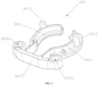
- the engaging member 341 has a generally U-shaped structure, and includes two engaging arms 3411 facing each other and a fixing part 3412 connected between the two engaging arms 3411.
- the fixing part 3412 is fixed on the connecting base 320.
- two fixing rings 3412a can be disposed at both ends of the fixing part 3412 respectively.
- Two fixing posts 3224 can be disposed on a side of the second cover 322 facing the receiving space 323.
- the two fixing rings 3412a can be respectively sleeved on the two fixing posts 3224 so that the fixing part 3412 is fixedly connected to the connecting base 320.
- the two engaging arms 3411 have a symmetrical arc-shaped sheet-like structure.
- An abutting portion 3413 is disposed on a surface of each of the engaging arms 3411 away from the second cover 322.
- the abutting portion 3413 is disposed at a portion of the engaging arm 3411 away from the fixing part 3412, and the abutting portion 3413 has a substantially columnar structure.
- the two engaging arms 3411 are made of an elastically deformable material, such as polyvinyl chloride (PVC).
- PVC polyvinyl chloride
- the unlocking member 342 is movably disposed on the connecting base 320. At least part of the unlocking member 342 is located in the receiving space 323, and the other part of the unlocking member 342 is located outside the receiving space 323 for operation.
- the unlocking member 342 is operable to move between a first locked position and a first unlocked position. When the unlocking member 342 is in the first locked position, the locking mechanism 340 is in the locked state, and when the unlocking member 342 is in the first unlocked position, the locking mechanism 340 is in the unlocked state.
- the unlocking member 342 may include a pushing part 3421, a connecting part 3422, and an operating part 3423.
- two pushing parts 3421 are provided.
- the two pushing parts 3421 are arranged opposite each other.
- the two pushing parts 3421 are connected through the connecting part 3422 to form a roughly U-shaped structure.
- Surfaces of the two pushing parts 3421 away from each other are both pushing inclined surfaces 3421a.
- Two pushing inclined surfaces 3421a gradually approach each other in a direction away from the connecting portion 3422.
- one of the pushing parts 3421 is provided with a sawtooth part 3421b.
- the sawtooth part 3421b may also be disposed on each of the two pushing parts 3421.
- two operating parts 3423 are provided.
- the two operating parts 3423 are respectively fixed to sides of the two pushing parts 3421 away from each other through two connecting rods 3424.
- the two operating parts 3423 may be in the form of push buttons, for example, and extend out of the receiving space 323 for operation. The user can drive the unlocking member 342 to move between the first locked position and the first unlocked position by pushing the two operating parts 3423 at the same time.
- one operating part 3423 may also be provided, and connected to the connecting part 3422.
- the operating part 3423 at least partially extends out of the receiving space 323 for operation.
- the operating part 3423 may also be located in the receiving space 323, and an operating member 360 at least partially extending out of the receiving space 323 may be additionally provided.
- the operating member 360 is connected to or abuts against the operating part 3423.
- the operating member 360 is operable to drive the unlocking member 342 to move between the first locked position and the first unlocked position through the operating part 3423.
- the operating member 360 may include a sliding part 361 and a driving part 362 that are connected to each other and arranged at an angle to each other.
- the sliding part 361 is located outside the receiving space 323 and can slide along an outer surface of the first cover 321.
- the sliding part 361 is provided with an operating protrusion 363, which can facilitate the user to operate.
- the first cover 321 is provided with a strip hole 3214 in communication with the receiving space 323.
- An end of the driving part 362 away from the sliding part 361 is inserted into the receiving space 323 through the strip hole 3214, and abuts against or is connected to the operating part 3423. In this way, by pushing the operating protrusion 363, the unlocking member 342 can be driven to move between the first locked position and the first unlocked position.
- the unlocking member 342 moves from the first locked position to the first unlocked position.
- the second magnetic member 343 is embedded in the rotatable member 344, and the rotatable member 344 is rotatably disposed in the receiving space 323.
- the connecting base 320 is connected to the fixed base 310, the rotatable member 344 is located above the first magnetic member 330.
- the second magnetic member 343 is a permanent magnet. Two ends of the second magnetic member 343 serve as a first magnetic pole 3431 and a second magnetic pole 3432 respectively.
- the first magnetic pole 3431 and the first magnetic member 330 face and attract each other.
- the second magnetic pole 3432 and the first magnetic member 330 face and repel each other.
- the first magnetic member 330 is the S pole and faces upward
- the first magnetic pole 3431 of the second magnetic member 343 is the N pole
- the second magnetic pole 3432 of the second magnetic member 343 is the S pole.
- the first magnetic pole 3431 is the S pole
- the second magnetic pole 3432 is the N pole.
- a connecting shaft 346 may be disposed in the receiving space 323. Both ends of the connecting shaft 346 are respectively fixed to the first cover 321 or the second cover 322.
- the second magnetic member 343 has a roughly cylindrical structure
- the rotatable member 344 has a roughly cylindrical structure.
- the second magnetic member 343 and the substantially middle part of the rotatable member 344 are sleeved on the connecting shaft 346 and can rotate around the connecting shaft 346.
- the rotatable member 344 has an annular outer wall.
- the rotatable member 344 is provided with a gear part 349.
- the gear part 349 protrudes from a side surface of the rotatable member 344.
- the sawtooth part 3421b is engaged with the gear part 349. In this way, when the unlocking member 342 moves between the first locked position and the second locked position, the rotation member 344 can be driven to rotate between the first rotation position and the second rotation position through the cooperation of the sawtooth part 3421b and the gear part 349.
- the reset member 345 is disposed between the unlocking member 342 and the connecting base 320.
- the reset member 345 is adapted to bias the unlocking member 342 to move toward the first locked position.
- the reset member 345 is a spring.
- Two reset members 345 may be provided.
- the two connecting rods 3424 may be respectively provided with first pushing protrusions 3424a.
- Each first pushing protrusion 3424a is provided with a first sleeved post 3424b.
- An inner wall of the first cover 321, that is, the surface of the first cover 321 facing the receiving space 323 is provided with two corresponding second pushing protrusions 3212.
- Each second pushing protrusion 3212 is provided with a second sleeved post 3213.
- each reset member 345 Both ends of each reset member 345 are respectively sleeved on the corresponding first sleeved post 3424b and the second sleeved post 3213, and abut against the corresponding first pushing protrusion 3424a and the second pushing protrusion 3212, so that the reset member 345 can be prevented from being displaced during deformation.
- the specific working principle of the locking mechanism 340 in this embodiment is as follows.
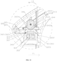
- the unlocking member 342 can be moved from the first locked position to the first unlocked position by pushing the operating member 360 or the operating part 3423. That is, the unlocking member 342 moves in a direction F1 shown in FIGS. 8 and 9 . In this case, the reset member 345 is compressed and deformed.
- the two pushing parts 3421 on the unlocking member 342 push against the two engaging arms 3411 on the engaging member 341 in a direction away from each other through the pushing inclined surfaces 3421a, so that the two engaging arms 3411 are elastically deformed and are disengaged from the engaging groove 312.
- the sawtooth part 3421b is engaged with the gear part 349 to push against a moving member 348 and the second magnetic member 343 to rotate around the connecting shaft 346 in a direction F2 to the second rotation position, so that the second magnetic pole 3432 faces the first magnetic member 330, as shown in FIGS. 10 and 11 .
- the connecting base 320 can be quickly removed from the fixed base 310 without overcoming additional locked force, which is convenient and efficient.
- the connecting base 320 When the connecting base 320 has been removed from the fixed base 310, the pushing force on the operating member 360 or the operating part 3423 is removed, so that the unlocking member 342 can be reset from the first unlocked position to the first locked position under the elastic restoring force of the reset member 345.
- the unlocking member 342 pushes the rotatable member 344 together with the second magnetic member 343 to rotate around the connecting shaft 346 in the direction F2 to the first rotational position through the engagement between the sawtooth part 3421b and the gear part 349, that is, the first magnetic pole 3431 is located below the second magnetic pole 3432.
- the first magnetic pole 3431 of the second magnetic member 343 is located below the second magnetic pole 3432, that is, the first magnetic pole 3431 can attract the first magnetic member 330, so that the connecting base 320 and the fixed base 310 can be automatically positioned quickly and accurately, and the engaging member 341 can be quickly engaged with the fixed base 310 without excessive manual correction, thus making the process of mounting the armrest body 200 on the frame 100 more convenient and efficient.
- the locking mechanism 340 may also include an engaging member 341, an unlocking member 342, a second magnetic member 343, a third magnetic member 347, a moving member 348, and a reset member 345.
- the configurations and arrangements of the engaging member 341, the unlocking member 342, and the reset member 345 are basically the same as those in the first embodiment, except that the pushing part 3421 of the engaging member 341 is not provided with the sawtooth part 3421b.
- the rotatable member 344 in which the second magnetic member 343 is embedded in the first embodiment is replaced with a moving member 348 in which the second magnetic member 343 and the third magnetic member 347 is embedded.
- the moving member 348 may be fixedly connected to the unlocking member 342, or the moving member 348 may be integrally formed with the unlocking member 342. In this embodiment, the moving member 348 is fixedly connected to ends of the two pushing parts 3421 away from the connecting part 3422.
- the moving member 348 may also be fixedly connected to only one of the two pushing parts 3421.
- the second magnetic member 343 and the third magnetic member 347 are embedded in the moving member 348 at an interval, and a distance between the second magnetic member 343 and the third magnetic member 347 should ensure that the magnetic field of the second magnetic member 343 and the magnetic field of the third magnetic member 347 will not affect each other obviously.
- the moving member 348 has a first moving position and a second moving position.
- the moving member 348 when the unlocking member 342 is in the first locked position, the moving member 348 is in the first moving position, and the second magnetic member 343 can face and attract the first magnetic member 330.
- the moving member 348 when the unlocking member 342 is in the first unlocked position, the moving member 348 is in the second moving position, and the third magnetic member 347 can face and repel the first magnetic member 330.
- the second magnetic member 343 is disposed at a side of the third magnetic member 347 in a direction indicated by the arrow of the direction F1.
- the second magnetic member 343 and the third magnetic member 347 are both permanent magnets.
- an end of the second magnetic member 343 adjacent to the fixed base 310 i.e., a lower end of the second magnetic member 343
- an end of the third magnetic member 347 adjacent to the fixed base 310 i.e., a lower end of the third magnetic member 347) is the S pole.
- the end of the second magnetic member 343 adjacent to the fixed base 310 i.e., the lower end of the second magnetic member 343
- the end of the third magnetic member 347 adjacent to the fixed base 310 i.e., the lower end of the third magnetic member 347) is the N pole.
- the second magnetic member 343 can also be replaced by an iron block or an object made of other ferromagnetic materials. In short, as long as the second magnetic member 343 and the first magnetic member 330 can attract each other when they face each other.
- the specific working principle of the locking mechanism 340 in this embodiment is as follows.
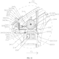
- the unlocking member 342 can be moved from the first locked position to the first unlocked position by pushing the operating member 360 or the operating part 3423, that is, the unlocking member 342 moves in the direction F1 shown in FIG. 16 .
- the reset member 345 is compressed and deformed.
- the two pushing parts 3421 on the unlocking member 342 push against the two abutting portions 3413 on the engaging member 341 in a direction away from each other through the pushing inclined surfaces 3421a, so that the two engaging arms 3411 are elastically deformed and are disengaged from the engaging groove 312.
- the moving member 348 is also driven to overcome the attraction force of the second magnetic member 343 and the first magnetic member 330 and move to the second moving position.
- the third magnetic member 347 faces and repels the first magnetic member 330. In this way, since the two engaging arms 3411 are disengaged from the engaging groove 312, and the third magnetic member 347 faces and repels the first magnetic member 330, the connecting base 320 can be removed from the fixed base 310 quickly without overcoming additional locked force, which is convenient and efficient.
- the connecting base 320 When the connecting base 320 has been removed from the fixed base 310, the pushing force on the operating member 360 or the operating part 3423 is removed, and the unlocking member 342 can be reset from the first unlocked position to the first locked position under the elastic restoring force of the reset member 345. At the same time, the unlocking member 342 drives the moving member 348 to return to the first moving position in a direction opposite to the direction F1.
- the connecting base 320 When it is necessary to mount the armrest body 200 onto the vehicle frame 100, it is only necessary to press the connecting base 320 to the fixed base 310, so that the second coupling portion 3223 is sleeved outside the first coupling portion 311, and the fixed base 310 is inserted into the receiving space 323 through the receiving hole 3222. At the same time, the two engaging arms 3411 of the engaging member 341 are elastically deformed to pass over the limiting boss 313 on the fixed base 310 and be engaged into the engaging groove 312.
- the connecting base 320 and the fixed base 310 can be automatically positioned quickly and accurately, and the engaging member 341 can be quickly engaged with the fixed base 310 without excessive manual correction, thus making the process of mounting the armrest body 200 on the vehicle frame 100 more convenient and efficient.
- the locking mechanism 340 may also include an engaging member 341, an unlocking member 342, a second magnetic member 343, a moving member 348, and a reset member 345.
- the configurations and arrangements of the engaging member341, the unlocking member 342, the second magnetic member 343, the moving member 348, and the reset member 345 in this embodiment are basically the same as those in the second embodiment, only except that that the third magnetic member 347 is not provided in this embodiment.
- the moving member 348 when the unlocking member 342 is in the first locked position, the moving member 348 is in the first moving position, and the second magnetic member 343 can face and forms a magnetic action with the first magnetic member 330.
- the moving member 348 is in the second moving position, and the second magnetic member 343 can be staggered from the first magnetic member 330 to remove the magnetic action.
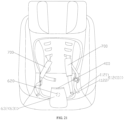
- the seat assembly 110 includes a seat part 112, a restraint belt 400, a locking buckle assembly 500, and a positioning mechanism 600. It should be noted that the seat assembly 110 can be disposed on the base of a handcart or a vehicle safety seat. In this embodiment, the seat assembly 110 disposed in the vehicle safety seat is taken as an example to illustrate the details of the restraint belt 400, the locking buckle assembly 500, and the positioning mechanism 600.
- the restraint belt 400 is disposed on the seat assembly 110 and has a restraining position and a non-restraining position.
- the restraint belt 400 includes a crotch belt.
- the crotch belt is disposed on the seat part 112 and correspondingly adapted to be disposed between two thighs of the occupant.
- An end of the restraint belt 400 is fixed on the seat part 112, and another end can be connected to one of locking buckles of the locking buckle assembly 500.
- FIG. 20 when the restraint belt 400 is in the restraining position, the restraint belt 400 can be used to restrict the occupant to the seat assembly 110.
- FIG. 20 when the restraint belt 400 is in the restraining position, the restraint belt 400 can be used to restrict the occupant to the seat assembly 110.
- FIG. 20 when the restraint belt 400 is in the restraining position, the restraint belt 400 can be used to restrict the occupant to the seat assembly 110.
- the restraint belt 400 when the restraint belt 400 is in the non-restraining position, it can facilitate the occupant to sit on and leave the seat assembly 110.
- the restraint belt 400 may also include other belt-like structures disposed on the handcart for restricting the movement of the occupant.
- the locking buckle assembly 500 includes a locking buckle configure to connect the restraint belt 400 to another pair of waist belts 700 for restraining the waist of the occupant.
- a locking buckle may be a five-way buckle.
- the positioning mechanism 600 is disposed between the restraint belt 400 and the seat part 112. When the locking buckle assembly 500 is in a locked state, the locking buckle assembly 500 can keep the restraint belt 400 in the restraining position. When the locking buckle assembly 500 is in an unlocked state, the positioning mechanism 600 can keep the restraint belt 400 in the non-restraining position.
- the positioning mechanism 600 may have different forms.
- the positioning mechanism 600 includes a protective piece 630 sleeved outside the restraint belt 400, and a fourth magnetic member 610 disposed on the seat part 112, and the fifth magnetic member 620 disposed on the restraint belt 400 or the protective piece 630.
- An end of the restraint belt 400 can extend out of the protective piece 630 to be connected to one of the locking buckles of the locking buckle assembly 500.
- the fourth magnetic member 610 and the fifth magnetic member 620 can attract each other to keep the restraint belt 400 in the non-restraining position.
- the fourth magnetic member 610 is fixed on the seat part 112 of the seat assembly 110 by, for example, machine sewing.
- the seat part 112 includes a seat cloth 1121 and a seat cushion 1122 laid on the seat cloth 1121.
- the fourth magnetic member 610 can be disposed on the seat cloth 1121 or on the seat cushion 1122.
- a through hole 1122a may be disposed on the seat cushion 1122.
- the protective piece 630 includes a first piece part 631 and a second piece part 632 that are connected to each other.
- the maximum width of the first piece part 631 is greater than the hole diameter of the through hole 1122a.
- An end of the second piece part 632 connected to the first piece part 631 has a width less than or equal to the hole diameter of the through hole 1122a.
- the protective piece 630 extends through the through hole 1122a.
- An end of the first piece part 631 away from the second piece part 632 can extends through the through hole 1122a and be located between the seat cloth 1121 and the seat cushion 1122 (that is, located below the seat cushion 1122).
- An end of the second piece part 632 away from the first piece part 631 extends through the seat cushion 1122 via the through hole 1122a and is located on a side of the seat cushion 1122 away from the seat cloth 1121, that is, located above the seat cushion 1122.
- the side of the seat cushion 1122 facing the seat cloth 1121 is called a first side
- the side of the seat cushion 1122 facing away from the seat cloth 1121 is called a second side.
- the first piece part 631 is located on the first side of the seat cushion 1122
- the second piece part 632 is located on the second side of the seat cushion 1122.
- a sleeve 634 is disposed at approximately the middle of the second piece portion 632.
- the restraint belt 400 is inserted into the second piece portion 632 and the sleeve 634.
- the sleeve 634 is generally a square piece of cloth, and the opposite sides of the square piece of cloth are fixed to the second piece part 632 by sewing (such as machine sewing).
- the restraint belt 400 is switched from the restraining position to the non-restraining position, and the fifth magnetic member 620 on the protective piece 630 can attract the fourth magnetic member 610 on the seat cloth 1121 or the seat cushion 1122, thereby keeping the restraint belt 400 in the non-restraining position, avoiding the shift of the protective piece 630 and the need to manually adjust the position of the restraint belt 400, which is convenient for a child to sit on.
- the fourth magnetic member 610 and the fifth magnetic member 620 may both be permanent magnets.
- the magnetic poles of the fourth magnetic member 610 and the fifth magnetic member 620 may be disposed so that the fourth magnetic member 610 and the fifth magnetic member 620 can attract each other when the restraint belt 400 is in the non-restraining position.
- one of the fourth magnetic member 610 and the fifth magnetic member 620 may be a permanent magnet, and the other one of the fourth magnetic member 610 and the fifth magnetic member 620 is an iron block or an object made of other ferromagnetic materials.
- the fifth magnetic member 620 is disposed on the protective piece 630, but which is not limited in the present application. When the positioning mechanism 600 does not includes the protective piece 630, the fifth magnetic member 620 may also be disposed on the restraint belt 400.
- the positioning mechanism 600 may further include a flexible resilient member 640 disposed in the protective piece 630.
- the flexible resilient member 640 may have a sheet-like structure made of a PVC material, a metal material, or other soft materials with certain flexibility.
- the flexible resilient member 640 extends from the first piece part 631 to the second piece part 632 to ensure the resilience of the flexible resilient member 640.
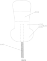
- the flexible resilient member 640 may include a first elastic part 641 and a second elastic part 642 connected to each other. The first elastic part 641 is located in the first piece part 631, and the second elastic part 642 is located in the second piece part 632.
- the first elastic part 641 of the flexible resilient member 640 extends through the through hole 1122a and is located on the first side of the seat cushion 1122. (i.e., located below the seat cushion 1122), and the second elastic part 642 is located on the second side of the seat cushion 1122 (i.e., located above the seat cushion 1122).
- the protective piece 630 is filled with a cushioning material, and the flexible resilient member 640 is located between the cushioning material and the restraint belt 400. In this way, the flexible resilient member 640 can be prevented from contacting the child, thereby improving the child's safety comfort.
- the flexible resilient member 640 in the protective piece 630 can be bent and deformed.
- the flexible resilient member 640 can automatically return to a normally straightened state under its own elastic restoring force, thereby driving the restraint belt 400 to automatically switch to the non-restraining position. In other words, the flexible resilient member 640 always moves the restraint belt 400 toward the non-restraining position.
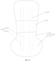
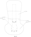
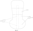
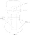
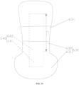
- the flexible resilient member 640 can have a variety of shapes, such as a single strip shape (as shown in FIG. 22 ), a U-shape (as shown in FIG. 23 ), or two opposite strips shape (as shown in FIG. 24 ), etc.
- the flexible resilient member 640 may also include a circular first elastic part 641 and a strip-shaped second elastic part 642.
- the maximum width W2 of the second elastic part 642 is smaller than the maximum width W1 of the first elastic part 641.
- an opening 633 can be disposed on the protective piece 630, and the flexible resilient member 640 can be removed from the protective piece 630 through the opening 633 to facilitate cleaning of the protective piece 630.
- a pocket can be sewn inside the protective piece 630, and the flexible resilient member 640 can be removably inserted into the pocket. When the protective piece 630 needs to be cleaned, the flexible resilient member 640 can also be taken out of the pocket.
- the flexible resilient member 640 can also be a spring, such as a fishbone spring.
- the fishbone spring has a hollow structure in the middle and has a strong resilience. When the locking mechanism 340 is unlocked, it is easier to drive the protective piece 630 together with the restraint belt 400 to pop up quickly.
- the fishbone spring is fixed in the protective piece 630 by sewing, such as machine sewing, and the protective piece 630 can be filled with a cushioning material to prevent the fish bone spring from contacting the child and improve the comfort of use.
- the cushioning material may be a foam with a foaming rate of 20 times, and may be made of common materials such as EPS.
- the fishbone spring in this embodiment also extends from the first piece part 631 to the second piece part 632 to ensure its own resilience.
- the fishbone spring is generally disposed along a longitudinal center axis of the protective piece 630.
- the fishbone spring can also be disposed on the left or right side of the longitudinal center axis of the protective piece 630, or two fishbone springs are arranged at an interval.
- a strip pocket can also be sewn at inner side of the protective piece at the longitudinal central axis to accommodate the fishbone spring.
- the positioning mechanism 600 includes the fourth magnetic member 610, the fifth magnetic member 620, and the flexible resilient component 640
- the restraint belt 400 can be automatically switched from the restraining position to the non-restraining position under the elastic restoring force of the flexible resilient member 640, and then, the protective piece 630 and the seat part 112 are quickly fixed to each other through the attracting effect between the fourth magnetic member 610 and the fifth magnetic member 620, and the restraint belt 400 is kept in the non-restraining position.
- the fifth magnetic member 620 and the flexible resilient member 640 may be spaced apart on the protective piece 630. In this way, due to the auxiliary positioning function of the fifth magnetic member 620, the length of the flexible resilient component 640 can be appropriately shortened to save material.
- the fifth magnetic member 620 may also be disposed on the sleeve 634.
- the flexible resilient member 640 is made of a ferromagnetic metal material, the flexible resilient member 640 and the fourth magnetic member 610 can attract each other, so that the fifth magnetic member 620 can be omitted, and the fourth magnetic member 610 are only disposed on the seat part 112.
- the protective piece 630 itself can also be made of a flexible rubber material. In this case, there is no need to provide the flexible resilient member 640 in the protective piece 630, and the protective piece 630 can drive the restraint belt 400 to automatically reset. It should be noted that in some embodiments, the positioning mechanism 600 may only include the protective piece 630 and the flexible resilient member 640 disposed in the protective piece 630, but does not include the fourth magnetic member 610 and the fifth magnetic member 620.
- the armrest mounting unit 300 and the handcart provided by the present application have at least the following technical effects.
- the magnetic force formed between the first magnetic member 330 and the locking mechanism 340 includes attractive force and/or repulsive force, so that the locking mechanism 340 can be switched between the locked state where the fixed base 310 is fixed onto the connecting base 320 and the unlocked state where the fixed base 310 is separated from the connecting base 320.
- the fixed base 310 and the connecting base 320 are respectively mounted on, for example, the armrest body 200 and the frame 100, the armrest body 200 can be quickly mounted on and removed from the frame 100, which is convenient to use.
Landscapes
- Engineering & Computer Science (AREA)
- Chemical & Material Sciences (AREA)
- Combustion & Propulsion (AREA)
- Transportation (AREA)
- Mechanical Engineering (AREA)
- Health & Medical Sciences (AREA)
- Public Health (AREA)
- Seats For Vehicles (AREA)
- Chairs For Special Purposes, Such As Reclining Chairs (AREA)
- Carriages For Children, Sleds, And Other Hand-Operated Vehicles (AREA)
Abstract
The present application discloses an armrest mounting unit (300) and a handcart. The armrest mounting unit (300) includes: a fixed base (310); a connecting base (320); a first magnetic member (330) fixed on one of the fixed base (310) and the connecting base (320); and a locking mechanism (340) disposed on the other one of the fixed base (310) and the connecting base (320). When the locking mechanism (340) is in a locked state, the connecting base (320) is fixable on the fixed base (310) through the locking mechanism (340). When the locking mechanism (340) is in an unlocked state, the connecting base (320) is separable from the fixed base (310). The first magnetic member (330) forms a magnetic action with the locking mechanism (340), to assist positioning and separation of the fixed base (310) and the connecting base (320).
Description
- The present application relates to the technical field of carries, and in particular, to an armrest mounting unit, a handcart, and a seat assembly.
- In most of the handcarts currently on the market, such as strollers or nursing carriers, an armrest body is detachably connected to a frame. However, during the process of mounting the armrest body, accurate positioning is required to lock the armrest body and the frame. In addition, during the process of removing the armrest body, a locked force between the armrest body and the frame also needs to be overcome, and after the armrest body is unlocked, the armrest cannot be released automatically, and thus additional force is required to remove the armrest body, resulting in that the use process is very inconvenient and the armrest body cannot be quickly mounted and removed.
- According to various embodiments of the present application, an armrest mounting unit, a handcart, and a seat assembly is provided.
- An armrest mounting unit includes: a fixed base; a connecting base; a first magnetic member fixed on one of the fixed base and the connecting base; and a locking mechanism disposed on the other one of the fixed base and the connecting base. When the locking mechanism is in a locked state, the connecting base is fixable on the fixed base through the locking mechanism. When the locking mechanism is in an unlocked state, the connecting base is separable from the fixed base. The first magnetic member forms a magnetic action with the locking mechanism, to assist positioning and separation of the fixed base and the connecting base.
- In the above armrest mounting unit, under the action of the magnetic force (including attractive force and/or repulsive force) formed between the first magnetic member and the locking mechanism, the locking mechanism can be switched between the locked state where the fixed base is fixed onto the connecting base and the unlocked state where the fixed base is separated from the connecting base. When the fixed base and the connecting base are respectively mounted on, for example, the armrest body and the frame, the armrest body can be quickly mounted on and removed from the frame, which is convenient to use.
- In an embodiment, the locking mechanism is disposed on the connecting base, and includes: an unlocking member operable to move between a first locked position and a first unlocked position; an engaging member disposed on the connecting base; and a second magnetic member movably disposed on the connecting base, and forms a magnetic action with the first magnetic member.
- In an embodiment, the locking mechanism further includes a rotatable member rotatably disposed at the connecting base and having a first rotation position and a second rotation position. The second magnetic member is disposed on the rotatable member. The second magnetic member includes two ends serving as a first magnetic pole and a second magnetic pole respectively. When the rotatable member is in the first rotation position, the first magnetic pole and the first magnetic member face and attract each other. When the rotatable member is in the second rotation position, the second magnetic pole and the first magnetic member face and repel each other. When the unlocking member is in the first locked position, the unlocking member drives the rotatable member to rotate to the first rotation position. When the unlocking member is in the first unlocked position, the unlocking member drives the rotatable member to rotate to the second rotation position.
- In an embodiment, the locking mechanism further includes a connecting shaft fixed to the connecting base. The rotatable member is sleeved on the connecting shaft and is rotable around the connecting shaft.
- In an embodiment, the unlocking member is provided with a sawtooth part. The rotatable member is provided with a gear part engageable with the unlocking member. The unlocking member drives the rotatable member to rotate through a cooperation of the sawtooth part and the gear part.
- In an embodiment, the unlocking member is movable between the first locked position and the first unlocked position. The unlocking member is provided with a sawtooth part. The sawtooth part is disposed in a moving direction of the unlocking member. The rotatable member is provided with a gear part engageable with the unlocking member. The gear part protrudes from a side surface of the rotatable member. The sawtooth part is engaged with the gear part.
- In an embodiment, the second magnetic member is fixedly connected to the unlocking member. When the unlocking member is in the first locked position, the second magnetic member faces and forms a magnetic action with the first magnetic member. When the unlocking member is in the first unlocked position, the second magnetic member is staggered from the first magnetic member to remove the magnetic action.
- In an embodiment, the second magnetic member is a permanent magnet; or the second magnetic member is made of a ferromagnetic material.
- In an embodiment, the locking mechanism further includes a third magnetic member. The second magnetic member and the third magnetic member are spaced apart from each other, and are fixedly connected to the unlocking member. When the unlocking member is in the first locked position, the second magnetic member faces and attracts the first magnetic member. When the unlocking member is in the first unlocked position, the third magnetic member faces and repels the first magnetic member.
- In an embodiment, the locking mechanism further includes a moving member. The second magnetic member and the third magnetic member are spaced apart on the moving member. The moving member is fixed to the unlocking member.
- In an embodiment, the engaging member includes an abutting portion. The unlocking member includes a pushing part. During a movement of the unlocking member from the first locked position to the first unlocked position, the pushing part pushes against the abutting portion so that the engaging member is disengaged from the fixed base.
- In an embodiment, the engaging member includes an engaging arm. The fixed base includes an engaging groove. When the unlocking member is in the first locked position, the engaging arm is engaged with the engaging groove. When the unlocking member is in the first unlocked position, the engaging arm is disengaged from the engaging groove.
- In an embodiment, the engaging member includes an abutting portion. The unlocking member includes a pushing part. During a movement of the unlocking member from the first locked position to the first unlocked position, the pushing part pushes against the abutting portion so that the engaging member is elastically deformed to be disengaged from the fixed base.
- In an embodiment, the engaging member includes an engaging arm. The abutting portion is disposed at the engaging arm. The fixed base includes an engaging groove. The pushing part includes a pushing inclined surface. During the movement of the unlocking member from the first locked position to the first unlocked position, the pushing inclined surface pushes against the abutting portion, so that the engaging arm is elastically deformed in a direction away from the engaging groove.
- In an embodiment, the engaging member further includes a fixing part connected to the engaging arm. The fixing part is fixed to the connecting base.
- In an embodiment, the unlocking member includes an operating part. The operating part is operable so that the unlocking member moves between the first locked position and the first unlocked position.
- In an embodiment, the locking mechanism further includes an operating member. The unlocking member includes an operating part. The operating member is connected to or abuts against the operating part. The operating member is operable to drive the unlocking member to move between the first locked position and the first unlocked position through the operating part.
- In an embodiment, the engaging member includes two engaging arms facing each other and a fixing part connected between the two engaging arms. The fixing part is fixed on the connecting base. The fixed base includes an annular engaging groove. The fixed base is located between the two engaging arms. Each of the two engaging arms is provided with an abutting portion. The unlocking member is provided with two pushing parts facing each other. When the unlocking member is in the first locked position, the two engaging arms are engaged with the engaging groove. During a movement of the unlocking member from the first locked position to the first unlocked position, the two pushing parts push against two abutting portions respectively so that the two engaging arms are elastically deformed in a direction away from each other to be disengaged from the engaging groove.
- In an embodiment, the unlocking member further includes two operating parts respectively fixedly connected to the two pushing parts. The two operating parts are operable to drive the two pushing parts to move.
- In an embodiment, the unlocking member further includes an operating part connected to the two pushing parts. The operating part is operable to drive the two pushing parts to move.
- In an embodiment, the locking mechanism further includes a reset member disposed between the unlocking member and the connecting base. The reset member is adapted to bias the unlocking member to move toward the first locked position.
- In an embodiment, the connecting base includes a first cover and a second cover. The first cover and the second cover enclose a receiving space. The engaging member, the second magnetic member, and at least part of the unlocking member is disposed in the receiving space.
- In an embodiment, the fixed base includes a first coupling portion; the connecting base includes a second coupling portion. When the connecting base is engaged with and locked with the fixed base, the second coupling portion is sleeved outside the first coupling portion.
- A handcart includes: a frame; an armrest body; and an armrest mounting unit as described on any one of the above embodiments. The fixed base is disposed on one of the frame and armrest body. The connecting base is disposed on the other one of the frame and armrest body. The armrest body is detachably mounted on the frame through the armrest mounting unit.
- In an embodiment, two armrest mounting units are provided; and two ends of the armrest body are detachably connected to two sides of the frame through the two armrest mounting units respectively.
- In an embodiment, the frame includes a seat assembly; the handcart further includes: a restraint belt disposed on the seat assembly and having a restraining position and a non-restraining position; a locking buckle assembly connected to the restraint belt and having a locked state and an unlocked state; and a positioning mechanism disposed between the restraint belt and the seat assembly. When the locking buckle assembly is in the locked state, the locking buckle assembly is connectable to the restraint belt to keep the restraint belt in the restraining position. When the locking buckle assembly is in an unlocked state, the positioning mechanism keeps the restraint belt in the non-restraining position.
- In an embodiment, the positioning mechanism includes a fourth magnetic member disposed on the seat assembly and a fifth magnetic member disposed on the restraint belt. The fourth magnetic member and the fifth magnetic member are capable of attracting each other to keep the restraint belt in the non-restraining position.
- In an embodiment, the positioning mechanism further includes a protective piece sleeved outside the restraint belt and a fourth magnetic member disposed on the seat assembly or a fifth magnetic member disposed on the protective piece. An end of the restraint belt is capable of extending out of the protective piece.
- In an embodiment, the positioning mechanism includes a protective piece sleeved outside the restraint belt and a flexible resilient member disposed in the protective piece. The flexible resilient member always moves the restraint belt toward the non-restraining position.
- In an embodiment, the flexible resilient member is made of a polyvinyl chloride material, or metal material.
- In an embodiment, the seat assembly includes a seat part configured to carry an occupant. The seat part includes a first side facing away from the occupant and a second side facing the occupant. The seat part is provided with a through hole. The protective piece includes a first piece part and a second piece part that are connected to each other. A maximum width of the first piece part is greater than a hole diameter of the through hole. An end of the second piece part connected to the first piece part has a width less than or equal to the hole diameter of the through hole. The protective piece extends through the through hole. The first piece part is located on the first side of the seat part, and the second piece part is located on the second side of the seat part.
- In an embodiment, the flexible resilient member extends from the first piece part to the second piece part.
- In an embodiment, the flexible resilient member includes a first elastic part and a second elastic part connected to each other. The first elastic part is located in the first piece part, and the second elastic part is located in the second piece part. A maximum width of the first elastic part is greater than a maximum width of the second elastic part.
- In an embodiment, the positioning mechanism further includes a fourth magnetic member disposed on the seat assembly and a fifth magnetic member disposed on the protective piece. The fourth magnetic member and the fifth magnetic member are capable of attracting each other to keep the restraint belt in the non-restraining position.
- In an embodiment, the positioning mechanism further includes a fourth magnetic member disposed on the seat assembly. The flexible resilient member is made of a ferromagnetic material. The flexible resilient member always moves the restraint belt toward the non-restraining position. The fourth magnetic member and the flexible resilient member are capable of attracting each other to keep the restraint belt in the non-restraining position.
- In an embodiment, the protective piece includes an opening. The flexible resilient member is removable from the protective piece through the opening. Or, a pocket is disposed on the protective piece, and the flexible resilient member is removably inserted into the pocket.
- In an embodiment, the flexible resilient member is a fishbone spring.
- In an embodiment, the fishbone spring is fixed in the protective piece by sewing.
- In an embodiment, the protective piece is filled with a cushioning material. The flexible resilient member is located between the cushioning material and the restraint belt.
- In an embodiment, the positioning mechanism includes a protective piece sleeved outside the restraint belt. The protective piece is made of a flexible rubber material.
- In an embodiment, the restraint belt includes a crotch belt adapted to be disposed between two thighs of an occupant. The positioning mechanism is disposed between the crotch belt and the seat assembly.
- A seat assembly includes: a seat part; a restraint belt disposed on the seat part and having a restraining position and a non-restraining position; a locking buckle assembly connected to the restraint belt and having a locked state and an unlocked state; and a positioning mechanism disposed between the restraint belt and the seat part. When the locking buckle assembly is in the locked state, the locking buckle assembly is connectable to the restraint belt to keep the restraint belt in the restraining position. When the locking buckle assembly is in the unlocked state, the positioning mechanism keeps the restraint belt in the non-restraining position.
- In an embodiment, the positioning mechanism includes a fourth magnetic member disposed on the seat part and a fifth magnetic member disposed on the restraint belt. The fourth magnetic member and the fifth magnetic member are capable of attracting each other to keep the restraint belt in the non-restraining position.
- In an embodiment, the positioning mechanism further includes: a protective piece sleeved outside the restraint belt; and a fourth magnetic member disposed on the seat part and a fifth magnetic member disposed on the protective piece. An end of the restraint belt is capable of extending out of the protective piece.
- In an embodiment, the positioning mechanism includes a protective piece sleeved outside the restraint belt and a flexible resilient member disposed in the protective piece. The flexible resilient member always moves the restraint belt toward the non-restraining position.
- In an embodiment, the flexible resilient member has a sheet-like structure made of a polyvinyl chloride material, or metal material.
- In an embodiment, the seat part includes a first side facing away from an occupant and a second side facing the occupant. The seat part is provided with a through hole. The protective piece includes a first piece part and a second piece part that are connected to each other. A maximum width of the first piece part is greater than a hole diameter of the through hole. An end of the second piece part connected to the first piece part has a width less than or equal to the hole diameter of the through hole. The protective piece extends through the through hole. The first piece part is located on the first side of the seat part, and the second piece part is located on the second side of the seat part.
- In an embodiment, the flexible resilient member extends from the first piece part to the second piece part.
- In an embodiment, the flexible resilient member includes a first elastic part and a second elastic part connected to each other. The first elastic part is located in the first piece part, and the second elastic part is located in the second piece part. A maximum width of the first elastic part is greater than a maximum width of the second elastic part.
- In an embodiment, the positioning mechanism further includes a fourth magnetic member disposed on the seat part and a fifth magnetic member disposed on the protective piece. The fourth magnetic member and the fifth magnetic member are capable of attracting each other to keep the restraint belt in the non-restraining position.
- In an embodiment, the positioning mechanism further includes a fourth magnetic member disposed on the seat part. The flexible resilient member is made of a ferromagnetic material. The flexible resilient member always moves the restraint belt toward the non-restraining position. The fourth magnetic member and the flexible resilient member are capable of attracting each other to keep the restraint belt in the non-restraining position.
- In an embodiment, the protective piece includes an opening; the flexible resilient member is removable from the protective piece through the opening. Or, a pocket is disposed on the protective piece, and the flexible resilient member is removably inserted into the pocket.
- In an embodiment, the flexible resilient member is a fishbone spring.
- In an embodiment, the fishbone spring is at least partially fixed in the protective piece by sewing.
- In an embodiment, the protective piece is filled with a cushioning material.
- In an embodiment, the positioning mechanism includes a protective piece sleeved outside the restraint belt. The protective piece is made of a flexible rubber material.
- In an embodiment, the restraint belt includes a crotch belt. The positioning mechanism is disposed between the crotch belt and the seat part.
-
-
FIG. 1 is a perspective schematic view of a handcart according to a first embodiment of the present application. -
FIG. 2 is an exploded view ofFIG. 1 . -
FIG. 3 is a perspective schematic view of an armrest body and an armrest mounting unit shown inFIG. 2 . -
FIG. 4 is a partial exploded view of the armrest body and the armrest mounting unit shown inFIG. 3 . -
FIG. 5 is a perspective schematic view of an engaging member shown inFIG. 4 . -
FIG. 6 is a perspective schematic view of an unlocking member shown inFIG. 4 . -
FIG. 7 is a perspective schematic view of an armrest body and an armrest mounting unit shown inFIG. 1 . -
FIG. 8 is a cross-sectional view taken along a line A-A inFIG. 7 , in which a locking mechanism is in a locked state, and an unlocking member includes two operating parts. -
FIG. 9 is a cross-sectional view taken along a line B-B inFIG. 7 , in which a locking mechanism is in a locked state, and an unlocking member includes two operating parts. -
FIG. 10 is another cross-sectional view taken along the line A-A inFIG. 7 , in which the locking mechanism is in an unlocked state, and the unlocking member includes two operating parts. -
FIG. 11 is another cross-sectional view taken along the line B-B inFIG. 7 , in which the locking mechanism is in the unlocked state, and the unlocking member includes two operating parts. -
FIG. 12 is yet another cross-sectional view taken along the line A-A inFIG. 7 , in which the locking mechanism is in the locked state, and the unlocking member includes one operating part. -
FIG. 13 is yet another cross-sectional view taken along the line B-B inFIG. 7 , in which the locking mechanism is in the unlocked state, and the unlocking member includes one operating part. -
FIG. 14 is another further cross-sectional view taken along the line A-A, and shows the armrest body and the armrest mounting unit, in which the locking mechanism is in the locked state, the unlocking member includes one operating part and the locking mechanism includes an operating member. -
FIG. 15 is another further cross-sectional view taken along the line A-A, and shows the armrest body and the armrest mounting unit, in which the locking mechanism is in the unlocked state, and the unlocking member includes one operating part and the locking mechanism includes the operating member. -
FIG. 16 is a partial cross-sectional view of an armrest mounting unit of the handcart according to a second embodiment of the present application, in which a locking mechanism is in a locked state. -
FIG. 17 is a perspective schematic view of the locking mechanism shown inFIG. 16 when being is in an unlocked state. -
FIG. 18 is a partial cross-sectional view of an armrest mounting unit in a handcart according to a third embodiment of the present application, in which a locking mechanism is in a locked state. -
FIG. 19 is a perspective schematic view of the locking mechanism shown inFIG. 18 when being in an unlocked state. -
FIG. 20 is a partial schematic view of a seat assembly according to an embodiment of the present application, in which a locking buckle assembly is in a locked state and a restraint belt is in a restraining position. -
FIG. 21 is another partial schematic view of the seat assembly shown inFIG. 20 , in which the locking buckle assembly is in an unlocked state and the restraint belt is in a non-restraining position. -
FIG. 22 is a perspective schematic view of a protective piece and a positioning mechanism according to yet another embodiment. -
FIG. 23 is a perspective schematic view of the protective piece and a flexible resilient member shown inFIG. 22 with another shape. -
FIG. 24 is a perspective schematic view of the protective piece and the flexible resilient member shown inFIG. 22 with yet another shape. -
FIG. 25 is a perspective schematic view of the protective piece and the flexible resilient member shown inFIG. 22 with another further shape. -
FIG. 26 is another perspective schematic view of the protective piece and the positioning mechanism shown inFIG. 22 . -
FIG. 27 is a perspective schematic view of a protective piece and a positioning mechanism of a handcart according to yet another embodiment, in which a flexible resilient member is a fishbone spring. -
FIG. 28 is a perspective schematic view of part of the fishbone spring shown inFIG. 27 , after moving out of the protective piece. -
FIG. 29 is a perspective schematic view of a protective piece and a positioning mechanism according to another embodiment. -
FIG. 30 is a perspective schematic view of a protective piece and a positioning mechanism according to yet another embodiment. - 100, Frame; 110, Seat Assembly; 111, Seat Post; 112, Seat Part; 1121, Seat Cloth; 1122, Seat Cushion; 1122a, Through Hole; 120, Handle Assembly; 130, Armrest Support Rod; 200, Armrest Body; 300, Armrest Mounting unit; 310, Fixed Base; 311, First Coupling Portion; 312, Engaging Groove; 313, Limiting Boss; 314, Mounting Cavity; 320, Connecting Base; 321, First Cover; 3211, Elastic Arm; 3212, Second Pushing Protrusion; 3213, Second Sleeved Post; 3214, Strip Hole; 322, Second Cover; 3221, Connecting Hole; 3222, Receiving Hole; 3223, Second Coupling Portion; 3224, Fixing Post; 323, Receiving Space; 330, First Magnetic member; 340, Locking Mechanism; 341, Engaging Member; 3411, Engaging Arm; 3412, Fixing Part; 3412a, Fixing Ring; 3413, Abutting Portion; 342, Unlocking Member; 3421, Pushing Part; 3421a, Pushing Inclined Surface; 3421b, Sawtooth Part; 3422, Connecting Part; 3423, Operating Part; 3424, Connecting Rod; 3424a, First Pushing Protrusion; 3424b, First Sleeved Post; 343, Second Magnetic Member; 3431, First Magnetic Pole; 3432, Second Magnetic Pole; 344, Rotatable Member; 345, Reset Member; 346, Connecting Shaft; 347, Third Magnetic Member; 348, Moving Member; 349, Gear Part; 350, Mounting Cover; 360, Operating Member; 361, Sliding Part; 362, Driving Part; 363, Operating Protrusion; 400, Restraint Belt; 500, Locking Buckle Assembly; 600, Positioning Mechanism; 610, Fourth Magnetic Member; 620, Fifth Magnetic Member; 630, Protective Piece; 631, First Piece Part; 632, Second Piece Part; 633, Opening; 634, Sleeve; 640, Flexible Resilient Member; 641, First Elastic Part; 642, Second Elastic Part; 700, Waist Belt.
- In order to make the object, technical solutions, and advantages of the present application clearer, the present application will be further described in detail below in conjunction with the accompanying drawings and specific embodiments. It should be understood that the specific embodiments described herein are only used to illustrate the present application and do not limit the protection scope of the present application.
- It should be noted that, when an element is referred to as being "fixed on" another element, it may be directly on the other element or there may also present an intermediate element. When an element is referred to as being "connected to" another element, it may be directly connected to the other element or there might present an intermediate element at the same time. The terms "vertical", "horizontal", "left", "right" and similar expressions used herein are only for the purpose of illustration, rather than presenting the only ways for implementation.
- Unless otherwise defined, all technical and scientific terms used herein have the same meanings as those commonly understood by those skilled in the art of the present application. The terms used in the description of the present application herein are only for the purpose of describing specific embodiments and are not intended to limit the present application. The term "and/or" used herein includes any and all combinations of one or more associated listed items.
- As shown in
FIG. 1 , an embodiment of the present application provides a handcart, such as a stroller or a nursing carrier, which includes aframe 100, anarmrest body 200, and anarmrest mounting unit 300. Thearmrest mounting unit 300, thearmrest body 200, and theframe 100 can be quickly mounted and removed, and are easy to use. - Specifically, as shown in
FIG. 1 , theframe 100 includes aseat assembly 110, ahandle assembly 120, and anarmrest support rod 130. Theseat assembly 110 is used to carry an occupant, and includes twoopposite seat posts 111 and aseat part 112 wrapped around the two seat posts 111 (seeFIG. 20 ). Thehandle assembly 120 is connected to theseat assembly 110 to facilitate a caregiver to push the handcart to move. Twoarmrest support rods 130 are provided. First ends of the twoarmrest support rods 130 are respectively connected to both sides of thehandle assembly 120. Correspondingly, twoarmrest mounting units 300 are provided. Thearmrest body 200 generally has a rod-shaped structure, and is used to restrict the occupant to theseat assembly 110. Both ends of thearmrest body 200 are detachably mounted on second ends of the twoarmrest support rods 130 through the twoarmrest mounting units 300. Alternatively, anarmrest mounting unit 300 can be disposed on only one side, and thearmrest mounting unit 300 can be configured to be rotatably connected to thearmrest support rod 130 on the other side. - Specifically, as shown in
FIGS. 2 to 4 , thearmrest mounting unit 300 includes a fixedbase 310 that can be locked or unlocked, a connectingbase 320, a firstmagnetic member 330, and alocking mechanism 340. In this embodiment, each of the seconds ends of the twoarmrest support rods 130 are provided with the fixedbase 310, and each of the two ends of thearmrest body 200 are provided with the connectingbase 320. Both ends of thearmrest body 200 are detachably connected to the twoarmrest support rods 130 respectively, through two connectingbases 320 and two fixedbase 310 being locked or unlocked. In other embodiments, the fixedbases 310 can also be disposed at both ends of thearmrest body 200, and the connectingbases 320 can be disposed at the second ends of the twoarmrest support rods 130. - Taking an
armrest mounting unit 300 located at an end of thearmrest body 200 as an example, the configuration and connection relationship of thearmrest mounting unit 300 are introduced in detail below. - Specifically, as shown in
FIG. 4 , the fixedbase 310 has a substantially columnar structure. Part of an outer wall of the fixedbase 310 protrudes to form a cylindricalfirst coupling portion 311. The fixedbase 310 is further provided with an annularengaging groove 312. In this embodiment, the engaginggroove 312 is spaced apart from thefirst coupling portion 311 and is located on a side of thefirst coupling portion 311 away from thearmrest support rod 130. That is, inFIG. 4 , the engaginggroove 312 is located above thefirst coupling portion 311. A groove wall of the engaginggroove 312 away from thefirst coupling portion 311, that is, an upper groove wall of the engaginggroove 312 forms a limitingboss 313. The firstmagnetic member 330 is a permanent magnet, and is disposed inside the fixedbase 310. In this embodiment, the S pole of the firstmagnetic member 330 is farther away from thearmrest support rod 130 than the N pole of the firstmagnetic member 330, that is, the firstmagnetic member 330 is arranged with the S pole facing upward. In other embodiments, the firstmagnetic member 330 can also be reversely arranged, that is, the N pole of the firstmagnetic member 330 is arranged to face upward. In this embodiment, as shown inFIG. 8 , the fixedbase 310 includes a mountingcavity 314. The firstmagnetic member 330 is inserted into the mountingcavity 314. A mountingcover 350 is pushed against the bottom of the firstmagnetic member 330, to prevent the firstmagnetic member 330 from falling off. - Specifically, as shown in
FIG. 4 , the connectingbase 320 includes afirst cover 321 and asecond cover 322 that are engaged with each other. A receivingspace 323 is formed between thefirst cover 321 and thesecond cover 322. Specifically, thefirst cover 321 may be provided with at least twoelastic arms 3211, and thesecond cover 322 may be provided with at least two corresponding connectingholes 3221. The at least twoelastic arms 3211 are engaged into the at least two connectingholes 3221, so that thefirst cover 321 is engaged with thesecond cover 322. Or, vice versa, for example, the connectinghole 3221 is disposed on thefirst cover 321, and theelastic arm 3211 that can be engaged into the connectinghole 3221 is disposed on thesecond cover 322, etc., and the present application is not limited thereto. In this embodiment, thefirst cover 321 is located on a side of thesecond cover 322 away from thearmrest support rod 130, that is, thefirst cover 321 is located above thesecond cover 322. Thesecond cover 322 includes areceiving hole 3222 that can be in communication with the receivingspace 323. When the connectingbase 320 is connected to the fixedbase 310, the fixedbase 310 is inserted into the receivingspace 323 through the receivinghole 3222, so that a magnetic action is formed between the fixedbase 310 and thelocking mechanism 340. In addition, a hole wall of the receivinghole 3222 forms asecond coupling portion 3223. When the connectingbase 320 is connected to the fixedbase 310, thesecond coupling portion 3223 is sleeved outside the first coupling portion 311 (seeFIG. 8 ). In this embodiment, the connectingbase 320 is connected to an end of thearmrest body 200. In other embodiments, the connectingbase 320 can also be integrally formed with thearmrest body 200. In other embodiments, the firstmagnetic member 330 can also be disposed on the connectingbase 320, and thelocking mechanism 340 can be disposed on the fixedbase 310. - Further, the
locking mechanism 340 is at least partially disposed in the receivingspace 323. A magnetic action can be formed between the firstmagnetic member 330 and thelocking mechanism 340, to assist the positioning and separation of the fixedbase 310 and the connectingbase 320. When thelocking mechanism 340 is in a locked state, the connectingbase 320 can be fixed on the fixedbase 310 through thelocking mechanism 340. When thelocking mechanism 340 is in an unlocked state, the connectingbase 320 can be separated from the fixedbase 310. - Optionally, the
locking mechanism 340 may be in a variety of forms. For example, in a first embodiment, as shown inFIG. 4 , thelocking mechanism 340 may include an engagingmember 341, an unlockingmember 342, a secondmagnetic member 343, arotatable member 344, and areset member 345. - Specifically, as shown in
FIG. 5 , the engagingmember 341 has a generally U-shaped structure, and includes two engagingarms 3411 facing each other and a fixingpart 3412 connected between the two engagingarms 3411. The fixingpart 3412 is fixed on the connectingbase 320. Specifically, referring toFIG. 4 , two fixingrings 3412a can be disposed at both ends of the fixingpart 3412 respectively. Two fixingposts 3224 can be disposed on a side of thesecond cover 322 facing the receivingspace 323. The two fixingrings 3412a can be respectively sleeved on the two fixingposts 3224 so that the fixingpart 3412 is fixedly connected to the connectingbase 320. The twoengaging arms 3411 have a symmetrical arc-shaped sheet-like structure. An abuttingportion 3413 is disposed on a surface of each of the engagingarms 3411 away from thesecond cover 322. In this embodiment, the abuttingportion 3413 is disposed at a portion of theengaging arm 3411 away from the fixingpart 3412, and the abuttingportion 3413 has a substantially columnar structure. The twoengaging arms 3411 are made of an elastically deformable material, such as polyvinyl chloride (PVC). When the two engagingarms 3411 is not elastically deformed, the two engagingarms 3411 can be engaged with two sides of the annularengaging groove 312. That is, the two engagingarms 3411 clamp the two sides of the fixedbase 310. When the two engagingarms 3411 are elastically deformed, the two engagingarms 3411 can be deformed in directions away from each other, so as to be disengaged from the engaginggrooves 312 respectively. - Further, as shown in
FIGS. 6 and9 , the unlockingmember 342 is movably disposed on the connectingbase 320. At least part of the unlockingmember 342 is located in the receivingspace 323, and the other part of the unlockingmember 342 is located outside the receivingspace 323 for operation. The unlockingmember 342 is operable to move between a first locked position and a first unlocked position. When the unlockingmember 342 is in the first locked position, thelocking mechanism 340 is in the locked state, and when the unlockingmember 342 is in the first unlocked position, thelocking mechanism 340 is in the unlocked state. - Specifically, as shown in
FIG. 6 , the unlockingmember 342 may include a pushingpart 3421, a connectingpart 3422, and anoperating part 3423. - As shown in
FIG. 6 , two pushingparts 3421 are provided. The two pushingparts 3421 are arranged opposite each other. The two pushingparts 3421 are connected through the connectingpart 3422 to form a roughly U-shaped structure. Surfaces of the two pushingparts 3421 away from each other are both pushinginclined surfaces 3421a. Two pushinginclined surfaces 3421a gradually approach each other in a direction away from the connectingportion 3422. In this embodiment, one of the pushingparts 3421 is provided with asawtooth part 3421b. In other embodiments, thesawtooth part 3421b may also be disposed on each of the two pushingparts 3421. - In this embodiment, as shown in
FIG. 6 , two operatingparts 3423 are provided. The twooperating parts 3423 are respectively fixed to sides of the two pushingparts 3421 away from each other through two connectingrods 3424. The twooperating parts 3423 may be in the form of push buttons, for example, and extend out of the receivingspace 323 for operation. The user can drive the unlockingmember 342 to move between the first locked position and the first unlocked position by pushing the two operatingparts 3423 at the same time. - In other embodiments, as shown in
FIGS. 12 and13 , oneoperating part 3423 may also be provided, and connected to the connectingpart 3422. Theoperating part 3423 at least partially extends out of the receivingspace 323 for operation. Alternatively, as shown inFIGS. 14 and15 , theoperating part 3423 may also be located in the receivingspace 323, and an operating member 360 at least partially extending out of the receivingspace 323 may be additionally provided. The operating member 360 is connected to or abuts against theoperating part 3423. The operating member 360 is operable to drive the unlockingmember 342 to move between the first locked position and the first unlocked position through theoperating part 3423. Specifically, the operating member 360 may include a slidingpart 361 and a drivingpart 362 that are connected to each other and arranged at an angle to each other. The slidingpart 361 is located outside the receivingspace 323 and can slide along an outer surface of thefirst cover 321. The slidingpart 361 is provided with an operating protrusion 363, which can facilitate the user to operate. Thefirst cover 321 is provided with astrip hole 3214 in communication with the receivingspace 323. An end of the drivingpart 362 away from the slidingpart 361 is inserted into the receivingspace 323 through thestrip hole 3214, and abuts against or is connected to theoperating part 3423. In this way, by pushing the operating protrusion 363, the unlockingmember 342 can be driven to move between the first locked position and the first unlocked position. In this embodiment, when theoperating part 3423 or the operating member 360 is pushed, the unlockingmember 342 moves from the first locked position to the first unlocked position. - Further, as shown in
FIGS. 7 to 9 , the secondmagnetic member 343 is embedded in therotatable member 344, and therotatable member 344 is rotatably disposed in the receivingspace 323. When the connectingbase 320 is connected to the fixedbase 310, therotatable member 344 is located above the firstmagnetic member 330. In this embodiment, the secondmagnetic member 343 is a permanent magnet. Two ends of the secondmagnetic member 343 serve as a firstmagnetic pole 3431 and a secondmagnetic pole 3432 respectively. When therotatable member 344 is in a first rotation position, the firstmagnetic pole 3431 and the firstmagnetic member 330 face and attract each other. When therotatable member 344 is in a second rotation position, the secondmagnetic pole 3432 and the firstmagnetic member 330 face and repel each other. As mentioned above, in this embodiment, since the firstmagnetic member 330 is the S pole and faces upward, the firstmagnetic pole 3431 of the secondmagnetic member 343 is the N pole, and the secondmagnetic pole 3432 of the secondmagnetic member 343 is the S pole. In other embodiments, if the firstmagnetic member 330 is the N pole and faces upward, the firstmagnetic pole 3431 is the S pole, and the secondmagnetic pole 3432 is the N pole. - Specifically, as shown in
FIGS. 8 and9 , a connectingshaft 346 may be disposed in the receivingspace 323. Both ends of the connectingshaft 346 are respectively fixed to thefirst cover 321 or thesecond cover 322. The secondmagnetic member 343 has a roughly cylindrical structure, and therotatable member 344 has a roughly cylindrical structure. The secondmagnetic member 343 and the substantially middle part of therotatable member 344 are sleeved on the connectingshaft 346 and can rotate around the connectingshaft 346. Therotatable member 344 has an annular outer wall. Therotatable member 344 is provided with agear part 349. Thegear part 349 protrudes from a side surface of therotatable member 344. Thesawtooth part 3421b is engaged with thegear part 349. In this way, when the unlockingmember 342 moves between the first locked position and the second locked position, therotation member 344 can be driven to rotate between the first rotation position and the second rotation position through the cooperation of thesawtooth part 3421b and thegear part 349. - Further, the
reset member 345 is disposed between the unlockingmember 342 and the connectingbase 320. Thereset member 345 is adapted to bias the unlockingmember 342 to move toward the first locked position. In this embodiment, thereset member 345 is a spring. Tworeset members 345 may be provided. The two connectingrods 3424 may be respectively provided with first pushingprotrusions 3424a. Each first pushingprotrusion 3424a is provided with a firstsleeved post 3424b. An inner wall of thefirst cover 321, that is, the surface of thefirst cover 321 facing the receivingspace 323 is provided with two corresponding second pushingprotrusions 3212. Each second pushingprotrusion 3212 is provided with a secondsleeved post 3213. Both ends of eachreset member 345 are respectively sleeved on the corresponding firstsleeved post 3424b and the secondsleeved post 3213, and abut against the corresponding first pushingprotrusion 3424a and the second pushingprotrusion 3212, so that thereset member 345 can be prevented from being displaced during deformation. - The specific working principle of the
locking mechanism 340 in this embodiment is as follows. - When it is necessary to remove the
armrest body 200 from theframe 100, as shown inFIGS. 8 and9 , the unlockingmember 342 can be moved from the first locked position to the first unlocked position by pushing the operating member 360 or theoperating part 3423. That is, the unlockingmember 342 moves in a direction F1 shown inFIGS. 8 and9 . In this case, thereset member 345 is compressed and deformed. During the movement of the unlockingmember 342, the two pushingparts 3421 on the unlockingmember 342 push against the two engagingarms 3411 on the engagingmember 341 in a direction away from each other through the pushinginclined surfaces 3421a, so that the two engagingarms 3411 are elastically deformed and are disengaged from the engaginggroove 312. Meanwhile, during the movement of the unlockingmember 342, thesawtooth part 3421b is engaged with thegear part 349 to push against a movingmember 348 and the secondmagnetic member 343 to rotate around the connectingshaft 346 in a direction F2 to the second rotation position, so that the secondmagnetic pole 3432 faces the firstmagnetic member 330, as shown inFIGS. 10 and11 . In this way, since the two engagingarms 3411 are disengaged from the engaginggroove 312, and the secondmagnetic pole 3432 faces and repels the firstmagnetic member 330, the connectingbase 320 can be quickly removed from the fixedbase 310 without overcoming additional locked force, which is convenient and efficient. When the connectingbase 320 has been removed from the fixedbase 310, the pushing force on the operating member 360 or theoperating part 3423 is removed, so that the unlockingmember 342 can be reset from the first unlocked position to the first locked position under the elastic restoring force of thereset member 345. At the same time, the unlockingmember 342 pushes therotatable member 344 together with the secondmagnetic member 343 to rotate around the connectingshaft 346 in the direction F2 to the first rotational position through the engagement between thesawtooth part 3421b and thegear part 349, that is, the firstmagnetic pole 3431 is located below the secondmagnetic pole 3432. - When it is necessary to mount the
armrest body 200 onto theframe 100, as shown inFIGS. 8 and9 , it is only necessary to press the connectingbase 320 to the fixedbase 310, so that thesecond coupling portion 3223 is sleeved outside thefirst coupling portion 311. The fixedbase 310 is inserted into the receivingspace 323 through the receivinghole 3222. At the same time, the two engagingarms 3411 of the engagingmember 341 are elastically deformed to pass over the limitingboss 313 on the fixedbase 310 and be engaged into the engaginggroove 312. Since the firstmagnetic pole 3431 of the secondmagnetic member 343 is located below the secondmagnetic pole 3432, that is, the firstmagnetic pole 3431 can attract the firstmagnetic member 330, so that the connectingbase 320 and the fixedbase 310 can be automatically positioned quickly and accurately, and the engagingmember 341 can be quickly engaged with the fixedbase 310 without excessive manual correction, thus making the process of mounting thearmrest body 200 on theframe 100 more convenient and efficient. - Optionally, in a second embodiment, as shown in
FIGS. 16 and17 , thelocking mechanism 340 may also include an engagingmember 341, an unlockingmember 342, a secondmagnetic member 343, a thirdmagnetic member 347, a movingmember 348, and areset member 345. - In this embodiment, as shown in
FIGS. 16 and17 , the configurations and arrangements of the engagingmember 341, the unlockingmember 342, and thereset member 345 are basically the same as those in the first embodiment, except that the pushingpart 3421 of the engagingmember 341 is not provided with thesawtooth part 3421b. Therotatable member 344 in which the secondmagnetic member 343 is embedded in the first embodiment is replaced with a movingmember 348 in which the secondmagnetic member 343 and the thirdmagnetic member 347 is embedded. The movingmember 348 may be fixedly connected to the unlockingmember 342, or the movingmember 348 may be integrally formed with the unlockingmember 342. In this embodiment, the movingmember 348 is fixedly connected to ends of the two pushingparts 3421 away from the connectingpart 3422. In other embodiments, the movingmember 348 may also be fixedly connected to only one of the two pushingparts 3421. The secondmagnetic member 343 and the thirdmagnetic member 347 are embedded in the movingmember 348 at an interval, and a distance between the secondmagnetic member 343 and the thirdmagnetic member 347 should ensure that the magnetic field of the secondmagnetic member 343 and the magnetic field of the thirdmagnetic member 347 will not affect each other obviously. The movingmember 348 has a first moving position and a second moving position. - Further, as shown in
FIG. 16 , when the unlockingmember 342 is in the first locked position, the movingmember 348 is in the first moving position, and the secondmagnetic member 343 can face and attract the firstmagnetic member 330. As shown inFIG. 17 , when the unlockingmember 342 is in the first unlocked position, the movingmember 348 is in the second moving position, and the thirdmagnetic member 347 can face and repel the firstmagnetic member 330. Specifically, the secondmagnetic member 343 is disposed at a side of the thirdmagnetic member 347 in a direction indicated by the arrow of the direction F1. The secondmagnetic member 343 and the thirdmagnetic member 347 are both permanent magnets. As mentioned above, in this embodiment, since the firstmagnetic member 330 is arranged with the S pole facing upward, an end of the secondmagnetic member 343 adjacent to the fixed base 310 (i.e., a lower end of the second magnetic member 343) is the N pole, and an end of the thirdmagnetic member 347 adjacent to the fixed base 310 (i.e., a lower end of the third magnetic member 347) is the S pole. In this way, when the secondmagnetic member 343 faces the firstmagnetic member 330, the secondmagnetic member 343 and the firstmagnetic member 330 can attract each other. When the thirdmagnetic member 347 faces the firstmagnetic member 330, the thirdmagnetic member 347 and the firstmagnetic member 330 can repel each other. In other embodiments, if the firstmagnetic member 330 is arranged with the N pole facing upward, the end of the secondmagnetic member 343 adjacent to the fixed base 310 (i.e., the lower end of the second magnetic member 343) is the S pole, and the end of the thirdmagnetic member 347 adjacent to the fixed base 310 (i.e., the lower end of the third magnetic member 347) is the N pole. In other embodiments, the secondmagnetic member 343 can also be replaced by an iron block or an object made of other ferromagnetic materials. In short, as long as the secondmagnetic member 343 and the firstmagnetic member 330 can attract each other when they face each other. - The specific working principle of the
locking mechanism 340 in this embodiment is as follows. - When it is necessary to remove the
armrest body 200 from theframe 100, as shown inFIG. 16 , the unlockingmember 342 can be moved from the first locked position to the first unlocked position by pushing the operating member 360 or theoperating part 3423, that is, the unlockingmember 342 moves in the direction F1 shown inFIG. 16 . In this case, thereset member 345 is compressed and deformed. During the movement of the lockingmember 342, the two pushingparts 3421 on the unlockingmember 342 push against the two abuttingportions 3413 on the engagingmember 341 in a direction away from each other through the pushinginclined surfaces 3421a, so that the two engagingarms 3411 are elastically deformed and are disengaged from the engaginggroove 312. Meanwhile, during the movement of the unlockingmember 342, the movingmember 348 is also driven to overcome the attraction force of the secondmagnetic member 343 and the firstmagnetic member 330 and move to the second moving position. The thirdmagnetic member 347 faces and repels the firstmagnetic member 330. In this way, since the two engagingarms 3411 are disengaged from the engaginggroove 312, and the thirdmagnetic member 347 faces and repels the firstmagnetic member 330, the connectingbase 320 can be removed from the fixedbase 310 quickly without overcoming additional locked force, which is convenient and efficient. When the connectingbase 320 has been removed from the fixedbase 310, the pushing force on the operating member 360 or theoperating part 3423 is removed, and the unlockingmember 342 can be reset from the first unlocked position to the first locked position under the elastic restoring force of thereset member 345. At the same time, the unlockingmember 342 drives the movingmember 348 to return to the first moving position in a direction opposite to the direction F1. - When it is necessary to mount the
armrest body 200 onto thevehicle frame 100, it is only necessary to press the connectingbase 320 to the fixedbase 310, so that thesecond coupling portion 3223 is sleeved outside thefirst coupling portion 311, and the fixedbase 310 is inserted into the receivingspace 323 through the receivinghole 3222. At the same time, the two engagingarms 3411 of the engagingmember 341 are elastically deformed to pass over the limitingboss 313 on the fixedbase 310 and be engaged into the engaginggroove 312. In this case, since the secondmagnetic member 343 faces and attracts the firstmagnetic member 330, the connectingbase 320 and the fixedbase 310 can be automatically positioned quickly and accurately, and the engagingmember 341 can be quickly engaged with the fixedbase 310 without excessive manual correction, thus making the process of mounting thearmrest body 200 on thevehicle frame 100 more convenient and efficient. - Optionally, in the third embodiment, as shown in
FIGS. 18 and19 , thelocking mechanism 340 may also include an engagingmember 341, an unlockingmember 342, a secondmagnetic member 343, a movingmember 348, and areset member 345. - As shown in
FIGS. 18 and19 , the configurations and arrangements of the engaging member341, the unlockingmember 342, the secondmagnetic member 343, the movingmember 348, and thereset member 345 in this embodiment are basically the same as those in the second embodiment, only except that that the thirdmagnetic member 347 is not provided in this embodiment. In this way, when the unlockingmember 342 is in the first locked position, the movingmember 348 is in the first moving position, and the secondmagnetic member 343 can face and forms a magnetic action with the firstmagnetic member 330. When the unlockingmember 342 is in the first unlocked position, the movingmember 348 is in the second moving position, and the secondmagnetic member 343 can be staggered from the firstmagnetic member 330 to remove the magnetic action. - The specific working principle of the
locking mechanism 340 in this embodiment is the same as that in the second embodiment, and which will not be repeated again herein. - In another embodiment of the present application, as shown in
FIGS. 20 and21 , theseat assembly 110 includes aseat part 112, arestraint belt 400, a lockingbuckle assembly 500, and apositioning mechanism 600. It should be noted that theseat assembly 110 can be disposed on the base of a handcart or a vehicle safety seat. In this embodiment, theseat assembly 110 disposed in the vehicle safety seat is taken as an example to illustrate the details of therestraint belt 400, the lockingbuckle assembly 500, and thepositioning mechanism 600. - The
restraint belt 400 is disposed on theseat assembly 110 and has a restraining position and a non-restraining position. In this embodiment, therestraint belt 400 includes a crotch belt. The crotch belt is disposed on theseat part 112 and correspondingly adapted to be disposed between two thighs of the occupant. An end of therestraint belt 400 is fixed on theseat part 112, and another end can be connected to one of locking buckles of the lockingbuckle assembly 500. As shown inFIG. 20 , when therestraint belt 400 is in the restraining position, therestraint belt 400 can be used to restrict the occupant to theseat assembly 110. As shown inFIG. 21 , when therestraint belt 400 is in the non-restraining position, it can facilitate the occupant to sit on and leave theseat assembly 110. In other embodiments, therestraint belt 400 may also include other belt-like structures disposed on the handcart for restricting the movement of the occupant. - The locking
buckle assembly 500 includes a locking buckle configure to connect therestraint belt 400 to another pair ofwaist belts 700 for restraining the waist of the occupant. For example, such locking buckle may be a five-way buckle. Thepositioning mechanism 600 is disposed between therestraint belt 400 and theseat part 112. When the lockingbuckle assembly 500 is in a locked state, the lockingbuckle assembly 500 can keep therestraint belt 400 in the restraining position. When the lockingbuckle assembly 500 is in an unlocked state, thepositioning mechanism 600 can keep therestraint belt 400 in the non-restraining position. - Optionally, the
positioning mechanism 600 may have different forms. For example, in an embodiment, as shown inFIGS. 20 and21 , thepositioning mechanism 600 includes aprotective piece 630 sleeved outside therestraint belt 400, and a fourthmagnetic member 610 disposed on theseat part 112, and the fifthmagnetic member 620 disposed on therestraint belt 400 or theprotective piece 630. An end of therestraint belt 400 can extend out of theprotective piece 630 to be connected to one of the locking buckles of the lockingbuckle assembly 500. The fourthmagnetic member 610 and the fifthmagnetic member 620 can attract each other to keep therestraint belt 400 in the non-restraining position. Specifically, the fourthmagnetic member 610 is fixed on theseat part 112 of theseat assembly 110 by, for example, machine sewing. In this embodiment, theseat part 112 includes a seat cloth 1121 and aseat cushion 1122 laid on the seat cloth 1121. The fourthmagnetic member 610 can be disposed on the seat cloth 1121 or on theseat cushion 1122. - Specifically, a through
hole 1122a may be disposed on theseat cushion 1122. Referring toFIG. 22 , theprotective piece 630 includes afirst piece part 631 and asecond piece part 632 that are connected to each other. The maximum width of thefirst piece part 631 is greater than the hole diameter of the throughhole 1122a. An end of thesecond piece part 632 connected to thefirst piece part 631 has a width less than or equal to the hole diameter of the throughhole 1122a. Theprotective piece 630 extends through the throughhole 1122a. An end of thefirst piece part 631 away from thesecond piece part 632 can extends through the throughhole 1122a and be located between the seat cloth 1121 and the seat cushion 1122 (that is, located below the seat cushion 1122). An end of thesecond piece part 632 away from thefirst piece part 631 extends through theseat cushion 1122 via the throughhole 1122a and is located on a side of theseat cushion 1122 away from the seat cloth 1121, that is, located above theseat cushion 1122. The side of theseat cushion 1122 facing the seat cloth 1121 is called a first side, and the side of theseat cushion 1122 facing away from the seat cloth 1121 is called a second side. Then, thefirst piece part 631 is located on the first side of theseat cushion 1122, and thesecond piece part 632 is located on the second side of theseat cushion 1122. In this embodiment, asleeve 634 is disposed at approximately the middle of thesecond piece portion 632. Therestraint belt 400 is inserted into thesecond piece portion 632 and thesleeve 634. Specifically, thesleeve 634 is generally a square piece of cloth, and the opposite sides of the square piece of cloth are fixed to thesecond piece part 632 by sewing (such as machine sewing). - In this way, as shown in
FIGS. 20 and21 , when the lockingbuckle assembly 500 is switched from the locked state to the unlocked state, therestraint belt 400 is switched from the restraining position to the non-restraining position, and the fifthmagnetic member 620 on theprotective piece 630 can attract the fourthmagnetic member 610 on the seat cloth 1121 or theseat cushion 1122, thereby keeping therestraint belt 400 in the non-restraining position, avoiding the shift of theprotective piece 630 and the need to manually adjust the position of therestraint belt 400, which is convenient for a child to sit on. The fourthmagnetic member 610 and the fifthmagnetic member 620 may both be permanent magnets. The magnetic poles of the fourthmagnetic member 610 and the fifthmagnetic member 620 may be disposed so that the fourthmagnetic member 610 and the fifthmagnetic member 620 can attract each other when therestraint belt 400 is in the non-restraining position. Alternatively, one of the fourthmagnetic member 610 and the fifthmagnetic member 620 may be a permanent magnet, and the other one of the fourthmagnetic member 610 and the fifthmagnetic member 620 is an iron block or an object made of other ferromagnetic materials. It should be noted that in this embodiment, the fifthmagnetic member 620 is disposed on theprotective piece 630, but which is not limited in the present application. When thepositioning mechanism 600 does not includes theprotective piece 630, the fifthmagnetic member 620 may also be disposed on therestraint belt 400. - Further, as shown in
FIG. 22 , thepositioning mechanism 600 may further include a flexibleresilient member 640 disposed in theprotective piece 630. Alternatively, the flexibleresilient member 640 may have a sheet-like structure made of a PVC material, a metal material, or other soft materials with certain flexibility. The flexibleresilient member 640 extends from thefirst piece part 631 to thesecond piece part 632 to ensure the resilience of the flexibleresilient member 640. Specifically, the flexibleresilient member 640 may include a firstelastic part 641 and a secondelastic part 642 connected to each other. The firstelastic part 641 is located in thefirst piece part 631, and the secondelastic part 642 is located in thesecond piece part 632. That is, when theprotective piece 630 is disposed to extend through the throughhole 1122a on theseat cushion 1122, the firstelastic part 641 of the flexibleresilient member 640 extends through the throughhole 1122a and is located on the first side of theseat cushion 1122. (i.e., located below the seat cushion 1122), and the secondelastic part 642 is located on the second side of the seat cushion 1122 (i.e., located above the seat cushion 1122). In this embodiment, theprotective piece 630 is filled with a cushioning material, and the flexibleresilient member 640 is located between the cushioning material and therestraint belt 400. In this way, the flexibleresilient member 640 can be prevented from contacting the child, thereby improving the child's safety comfort. - In this way, when the locking
buckle assembly 500 is in the locked state and therestraint belt 400 is in the restraining position, the flexibleresilient member 640 in theprotective piece 630 can be bent and deformed. When the lockingbuckle assembly 500 is in the unlocked state, the flexibleresilient member 640 can automatically return to a normally straightened state under its own elastic restoring force, thereby driving therestraint belt 400 to automatically switch to the non-restraining position. In other words, the flexibleresilient member 640 always moves therestraint belt 400 toward the non-restraining position. - Optionally, the flexible
resilient member 640 can have a variety of shapes, such as a single strip shape (as shown inFIG. 22 ), a U-shape (as shown inFIG. 23 ), or two opposite strips shape (as shown inFIG. 24 ), etc. As shown inFIG. 25 , the flexibleresilient member 640 may also include a circular firstelastic part 641 and a strip-shaped secondelastic part 642. The maximum width W2 of the secondelastic part 642 is smaller than the maximum width W1 of the firstelastic part 641. Such an arrangement can ensure that the flexibleresilient member 640 has greater elastic resilience. - Further, as shown in
FIG. 26 , anopening 633 can be disposed on theprotective piece 630, and the flexibleresilient member 640 can be removed from theprotective piece 630 through theopening 633 to facilitate cleaning of theprotective piece 630. Alternatively, a pocket can be sewn inside theprotective piece 630, and the flexibleresilient member 640 can be removably inserted into the pocket. When theprotective piece 630 needs to be cleaned, the flexibleresilient member 640 can also be taken out of the pocket. - In some embodiments, as shown in
FIGS. 27 and28 , the flexibleresilient member 640 can also be a spring, such as a fishbone spring. The fishbone spring has a hollow structure in the middle and has a strong resilience. When thelocking mechanism 340 is unlocked, it is easier to drive theprotective piece 630 together with therestraint belt 400 to pop up quickly. In this embodiment, the fishbone spring is fixed in theprotective piece 630 by sewing, such as machine sewing, and theprotective piece 630 can be filled with a cushioning material to prevent the fish bone spring from contacting the child and improve the comfort of use. Alternatively, the cushioning material may be a foam with a foaming rate of 20 times, and may be made of common materials such as EPS. The fishbone spring in this embodiment also extends from thefirst piece part 631 to thesecond piece part 632 to ensure its own resilience. In this embodiment, the fishbone spring is generally disposed along a longitudinal center axis of theprotective piece 630. In other embodiments, the fishbone spring can also be disposed on the left or right side of the longitudinal center axis of theprotective piece 630, or two fishbone springs are arranged at an interval. Specifically, a strip pocket can also be sewn at inner side of the protective piece at the longitudinal central axis to accommodate the fishbone spring. - In some embodiments, as shown in
FIG. 29 , if thepositioning mechanism 600 includes the fourthmagnetic member 610, the fifthmagnetic member 620, and the flexibleresilient component 640, when the lockingbuckle assembly 500 is switched from the locked state to the unlocked state, therestraint belt 400 can be automatically switched from the restraining position to the non-restraining position under the elastic restoring force of the flexibleresilient member 640, and then, theprotective piece 630 and theseat part 112 are quickly fixed to each other through the attracting effect between the fourthmagnetic member 610 and the fifthmagnetic member 620, and therestraint belt 400 is kept in the non-restraining position. In this embodiment, the fifthmagnetic member 620 and the flexibleresilient member 640 may be spaced apart on theprotective piece 630. In this way, due to the auxiliary positioning function of the fifthmagnetic member 620, the length of the flexibleresilient component 640 can be appropriately shortened to save material. In another embodiment, the fifthmagnetic member 620 may also be disposed on thesleeve 634. - In some embodiments, as shown in
FIG. 30 , if the flexibleresilient member 640 is made of a ferromagnetic metal material, the flexibleresilient member 640 and the fourthmagnetic member 610 can attract each other, so that the fifthmagnetic member 620 can be omitted, and the fourthmagnetic member 610 are only disposed on theseat part 112. In such an embodiment, it should ensure that the length L1 (refer toFIG. 30 ) of the secondelastic part 642 of the flexibleresilient member 640 is greater than the shortest length L2 (refer toFIG. 20 ) from the throughhole 1122a to the fourthmagnetic member 610, so that when therestraint belt 400 is in the non-restraining position, the flexibleresilient member 640 can at least partially face and attract the fourthmagnetic member 610. - In other embodiments, the
protective piece 630 itself can also be made of a flexible rubber material. In this case, there is no need to provide the flexibleresilient member 640 in theprotective piece 630, and theprotective piece 630 can drive therestraint belt 400 to automatically reset. It should be noted that in some embodiments, thepositioning mechanism 600 may only include theprotective piece 630 and the flexibleresilient member 640 disposed in theprotective piece 630, but does not include the fourthmagnetic member 610 and the fifthmagnetic member 620. - The
armrest mounting unit 300 and the handcart provided by the present application have at least the following technical effects. - In the above-mentioned
armrest mounting unit 300, the magnetic force formed between the firstmagnetic member 330 and thelocking mechanism 340 includes attractive force and/or repulsive force, so that thelocking mechanism 340 can be switched between the locked state where the fixedbase 310 is fixed onto the connectingbase 320 and the unlocked state where the fixedbase 310 is separated from the connectingbase 320. When the fixedbase 310 and the connectingbase 320 are respectively mounted on, for example, thearmrest body 200 and theframe 100, thearmrest body 200 can be quickly mounted on and removed from theframe 100, which is convenient to use. - The technical features of the embodiments above may be combined arbitrarily. To make the description concise, not all possible combinations of the technical features in the above embodiments are described. However, as long as there are no contradictions in the combinations of these technical features, all of the combinations should be considered to be within the scope of the specification.
- The embodiments above only represent several implementation modes of the present application, and the description thereof is relatively specific and detailed, but it should not be construed as limiting the scope of the patent. It should be noted that for those skilled in the art, various modifications and improvements may be made without departing from the concept of the present application, and all these modifications and improvements fall within the protection scope of the present application. Therefore, the scope of protection of the present application shall be subject to the appended claims.
Claims (15)
- An armrest mounting unit (300), comprising:a fixed base (310);a connecting base (320);a first magnetic member (330) fixed on one of the fixed base (310) and the connecting base (320); anda locking mechanism (340) disposed on the other one of the fixed base (310) and the connecting base (320),wherein when the locking mechanism (340) is in a locked state, the connecting base (320) is fixable on the fixed base (310) through the locking mechanism (340), and when the locking mechanism (340) is in an unlocked state, the connecting base (320) is separable from the fixed base (310), andwherein the first magnetic member (330) forms a magnetic action with the locking mechanism (340), to assist positioning and separation of the fixed base (310) and the connecting base (320).
- The armrest mounting unit (300) according to claim 1, wherein the locking mechanism (340) is disposed on the connecting base (320), and comprises:an unlocking member (342) operable to move between a first locked position and a first unlocked position;an engaging member (341) disposed on the connecting base (320); anda second magnetic member (343) movably disposed on the connecting base (320), and forming a magnetic action with the first magnetic member (330),optionally, wherein the locking mechanism (340) further comprises:a rotatable member (344) rotatably disposed at the connecting base (320), and having a first rotation position and a second rotation position,wherein the second magnetic member (343) is disposed on the rotatable member (344); the second magnetic member (343) comprises two ends serving as a first magnetic pole (3431) and a second magnetic pole (3432) respectively; when the rotatable member (344) is in the first rotation position, the first magnetic pole (3431) and the first magnetic member (330) face and attract each other; and when the rotatable member (344) is in the second rotation position, the second magnetic pole (3432) and the first magnetic member (330) face and repel each other; and wherein when the unlocking member (342) is in the first locked position, the unlocking member (342) drives the rotatable member (344) to rotate to the first rotation position; and when the unlocking member (342) is in the first unlocked position, the unlocking member (342) drives the rotatable member (344) to rotate to the second rotation position,more optionally, wherein the locking mechanism (340) further comprises:a connecting shaft (346) fixed to the connecting base (320);wherein the rotatable member (344) is sleeved on the connecting shaft (346) and is rotable around the connecting shaft (346).
- The armrest mounting unit (300) according to claim 2, wherein the unlocking member (342) is provided with a sawtooth part (3421b), and the rotatable member (344) is provided with a gear part (349) engageable with the unlocking member (342);wherein the unlocking member (342) drives the rotatable member (344) to rotate through a cooperation of the sawtooth part (3421b) and the gear part (349);and/or, wherein the unlocking member (342) is movable between the first locked position and the first unlocked position; the sawtooth part (3421b) is disposed in a moving direction of the unlocking member (342); the gear part (349) protrudes from a side surface of the rotatable member (344); and the sawtooth part (3421b) is engaged with the gear part (349).
- The armrest mounting unit (300) according to claim 2 or 3, wherein: the second magnetic member (343) is fixedly connected to the unlocking member (342); when the unlocking member (342) is in the first locked position, the second magnetic member (347) faces and forms a magnetic action with the first magnetic member (330); and when the unlocking member (342) is in the first unlocked position, the second magnetic member (347) is staggered from the first magnetic member (330) to remove the magnetic action,
optionally, wherein the second magnetic member (343) is a permanent magnet; or the second magnetic member (343) is made of a ferromagnetic material. - The armrest mounting unit (300) according to any one of claims 2 to 4, wherein the locking mechanism (340) further comprises a third magnetic member (347); and the second magnetic member (343) and the third magnetic member (347) are spaced apart from each other, and are fixedly connected to the unlocking member (342); and wherein when the unlocking member (342) is in the first locked position, the second magnetic member (347) faces and attracts the first magnetic member (330); and when the unlocking member (342) is in the first unlocked position, the third magnetic member (347) faces and repels the first magnetic member (330),
optionally, wherein: the locking mechanism (340) further comprises a moving member (348); the second magnetic member (343) and the third magnetic member (347) are spaced apart on the moving member (348); and the moving member (348) is fixed to the unlocking member (342). - The armrest mounting unit (300) according to any one of claims 2 to 5, wherein: the engaging member (341) comprises an abutting portion (3413); the unlocking member (342) comprises a pushing part (3421); during a movement of the unlocking member (342) from the first locked position to the first unlocked position, the pushing part (3421) pushes against the abutting portion (3413) so that the engaging member (341) is disengaged from the fixed base (310),
and/or, wherein: the engaging member (341) comprises an engaging arm (3411); the fixed base (310) comprises an engaging groove (312); when the unlocking member (342) is in the first locked position, the engaging arm (3411) is engaged with the engaging groove (312); and when the unlocking member (342) is in the first unlocked position, the engaging arm (3411) is disengaged from the engaging groove (312). - The armrest mounting unit (300) according to any one of claims 2 to 6, wherein: the engaging member (341) comprises an abutting portion (3413); the unlocking member (342) comprises a pushing part (3421); during a movement of the unlocking member (342) from the first locked position to the first unlocked position, the pushing part (3421) pushes against the abutting portion (3413) so that the engaging member (341) is elastically deformed to be disengaged from the fixed base (310);optionally, wherein: the engaging member (341) comprises an engaging arm (3411); the abutting portion (3413) is disposed at the engaging arm (3411); the fixed base (310) comprises an engaging groove (312); the pushing part (3421) comprises a pushing inclined surface (3421a), and during the movement of the unlocking member (342) from the first locked position to the first unlocked position, the pushing inclined surface (3421a) pushes against the abutting portion (3413), so that the engaging arm (3411) is elastically deformed in a direction away from the engaging groove (312);more optionally, wherein the engaging member (341) further comprises a fixing part (3412) connected to the engaging arm (3411); and wherein the fixing part (3412) is fixed to the connecting base (320).
- The armrest mounting unit (300) according to any one of claims 2 to 7, wherein the locking mechanism (340) further comprises an operating member (360); the unlocking member (342) comprises an operating part (3423); the operating member (360) is connected to or abuts against the operating part (3423); and the operating member (360) is operable to drive the unlocking member (342) to move between the first locked position and the first unlocked position through the operating part (3423),optionally, wherein the engaging member (341) comprises two engaging arms (3411) facing each other and a fixing part (3412) connected between the two engaging arms (3411); wherein the fixing part (3412) is fixed on the connecting base (320); the fixed base (310) comprises an annular engaging groove (312); the fixed base (310) is located between the two engaging arms (3411); each of the two engaging arms (3411) is provided with an abutting portion (3413); the unlocking member (342) is provided with two pushing parts (3421) facing each other; and wherein when the unlocking member (342) is in the first locked position, the two engaging arms (3411) are engaged with the engaging groove (312); during a movement of the unlocking member (342) from the first locked position to the first unlocked position, the two pushing parts (3421) push against two abutting portions (3413) respectively so that the two engaging arms (3411) are elastically deformed in a direction away from each other to be disengaged from the engaging groove (312),more optionally, wherein one or two operating part (3423) are provided; and the one or two operating part (3423) are respectively connected to the two pushing parts (3421); and wherein the one or two operating part (3423) are operable to drive the two pushing parts (3421) to move.
- The armrest mounting unit (300) according to any one of claims 2 to 8, wherein the locking mechanism (340) further comprises a reset member (345) disposed between the unlocking member (342) and the connecting base (320); and the reset member (345) is adapted to bias the unlocking member (342) to move toward the first locked position,and/or, wherein: the connecting base (320) comprises a first cover (321) and a second cover (322); and wherein the first cover (321) and the second cover (322) enclose a receiving space (323); and the engaging member (341), the second magnetic member (343), and at least part of the unlocking member (342) is disposed in the receiving space (323),and/or, wherein the unlocking member (342) comprises an operating part (3423); and wherein the operating part (3423) is operable so that the unlocking member (342) moves between the first locked position and the first unlocked position.
- The armrest mounting unit (300) according to any one of claims 1 to 9, wherein: the fixed base (310) comprises a first coupling portion (311); the connecting base (320) comprises a second coupling portion (3223); and when the connecting base (320) is engaged with and locked with the fixed base (310), the second coupling portion (3223) is sleeved outside the first coupling portion (311).
- A handcart, comprising:a frame (100);an armrest body (200); andan armrest mounting unit (300) according to any one of claims 1 to 10,wherein the fixed base (310) is disposed on one of the frame (100) and armrest body (200);the connecting base (320) is disposed on the other one of the frame (100) and armrest body (200); and the armrest body (200) is detachably mounted on the frame (100) through the armrest mounting unit (300).
- The handcart according to claim 11, wherein the frame (100) comprises a seat assembly (110), the handcart further comprises:a restraint belt (400) disposed on the seat assembly (110) and having a restraining position and a non-restraining position;a locking buckle assembly (500) connected to the restraint belt (400) and having a locked state and an unlocked state; anda positioning mechanism (600) disposed between the restraint belt (400) and the seat assembly (110);wherein when the locking buckle assembly (500) is in the locked state, the locking buckle assembly (500) is connectable to the restraint belt (400) to keep the restraint belt (400) in the restraining position, and when the locking buckle assembly (500) is in an unlocked state, the positioning mechanism (600) keeps the restraint belt (400) in the non-restraining position.
- The handcart according to claim 12, wherein the positioning mechanism (600) comprises a fourth magnetic member (610) disposed on the seat assembly (110), andwherein the the positioning mechanism (600) further comprises a fifth magnetic member (620) disposed on the restraint belt (400); and wherein the fourth magnetic member (610) and the fifth magnetic member (620) are capable of attracting each other to keep the restraint belt (400) in the non-restraining position,and/or, wherein the positioning mechanism (600) further comprises a protective piece (630) sleeved outside the restraint belt (400) and a fifth magnetic member (620) disposed on the protective piece (630); and wherein an end of the restraint belt (400) is capable of extending out of the protective piece (630).
- The handcart according to claim 12 or 13, wherein the positioning mechanism (600) comprises a protective piece (630) sleeved outside the restraint belt (400) and a flexible resilient member (640) disposed in the protective piece (630); and wherein the flexible resilient member (640) always moves the restraint belt (400) toward the non-restraining position;optionally, wherein the seat assembly (110) comprises a seat part (112) configured to carry an occupant; and wherein the seat part (112) comprises a first side facing away from the occupant and a second side facing the occupant; the seat part (112) is provided with a through hole (1122a); the protective piece (630) comprises a first piece part (631) and a second piece part (632) that are connected to each other; a maximum width of the first piece part (631) is greater than a hole diameter of the through hole (1122a); an end of the second piece part (632) connected to the first piece part (631) has a width less than or equal to the hole diameter of the through hole (1122a); the protective piece (630) extends through the through hole (1122a); the first piece part (631) is located on the first side of the seat part (112), and the second piece part (632) is located on the second side of the seat part (112),more optionally, wherein the flexible resilient member (640) extends from the first piece part (631) to the second piece part (632,even more optionally, wherein the flexible resilient member (640) comprises a first elastic part (641) and a second elastic part (642) connected to each other; and wherein the first elastic part (641) is located in the first piece part (631), the second elastic part (642) is located in the second piece part (632), and a maximum width of the first elastic part (641) is greater than a maximum width of the second elastic part (642).
- The handcart according to claim 14, wherein the positioning mechanism (600) further comprises a fourth magnetic member (610) disposed on the seat assembly (110) and a fifth magnetic member (620) disposed on the protective piece (630); and wherein the fourth magnetic member (610) and the fifth magnetic member (620) are capable of attracting each other to keep the restraint belt (400) in the non-restraining position,and/or, wherein the positioning mechanism (600) further comprises a fourth magnetic member (610) disposed on the seat assembly (110); the flexible resilient member (640) is made of a ferromagnetic material; and the flexible resilient member (640) always moves the restraint belt (400) toward the non-restraining position; and wherein the fourth magnetic member (610) and the flexible resilient member (640) are capable of attracting each other to keep the restraint belt (400) in the non-restraining position,and/or, wherein the protective piece (630) comprises an opening (633), the flexible resilient member (640) is removable from the protective piece (630) through the opening (633);or, wherein a pocket is disposed on the protective piece (630), and the flexible resilient member (640) is removably inserted into the pocket,and/or, wherein the protective piece (630) is filled with a cushioning material; and wherein the flexible resilient member (640) is located between the cushioning material and the restraint belt (400).
Applications Claiming Priority (1)
| Application Number | Priority Date | Filing Date | Title |
|---|---|---|---|
| CN202310175777.0A CN118545141A (en) | 2023-02-24 | 2023-02-24 | Armrest Mounting Units, Carts and Seat Assemblies |
Publications (1)
| Publication Number | Publication Date |
|---|---|
| EP4420954A1 true EP4420954A1 (en) | 2024-08-28 |
Family
ID=90057506
Family Applications (1)
| Application Number | Title | Priority Date | Filing Date |
|---|---|---|---|
| EP24159292.2A Pending EP4420954A1 (en) | 2023-02-24 | 2024-02-23 | Armrest mounting units, handcarts and seat components |
Country Status (4)
| Country | Link |
|---|---|
| US (1) | US20240286663A1 (en) |
| EP (1) | EP4420954A1 (en) |
| JP (2) | JP7739498B2 (en) |
| CN (1) | CN118545141A (en) |
Citations (4)
| Publication number | Priority date | Publication date | Assignee | Title |
|---|---|---|---|---|
| US20160029812A1 (en) * | 2014-08-01 | 2016-02-04 | Thorley Industries Llc | Infant chairs |
| EP3293043A1 (en) * | 2016-09-13 | 2018-03-14 | BOS GmbH & Co. KG | Vehicle seat |
| EP3514064A1 (en) * | 2018-01-19 | 2019-07-24 | AMI Industries, Inc. | Aircraft passenger seat extended armrest |
| JP2020117205A (en) * | 2019-01-28 | 2020-08-06 | ニューウェルブランズ・ジャパン合同会社 | Childcare equipment with seat |
Family Cites Families (5)
| Publication number | Priority date | Publication date | Assignee | Title |
|---|---|---|---|---|
| JPS589818Y2 (en) * | 1980-05-01 | 1983-02-22 | コンビ株式会社 | Inclination angle adjuster for protective frames for floating carriages, etc. |
| JP3746110B2 (en) * | 1996-09-24 | 2006-02-15 | コンビ株式会社 | Lock mechanism for guard arm for baby seat |
| CN100395135C (en) | 2002-09-12 | 2008-06-18 | 株式会社东仁技研 | Multipurpose Child Vehicle Seat |
| CN207173703U (en) | 2017-08-02 | 2018-04-03 | 好孩子儿童用品有限公司 | Preceding handrail attachment structure and there is its baby seat pocket, children trolley |
| JP6910665B1 (en) | 2020-02-20 | 2021-07-28 | コンビ株式会社 | Childcare equipment and guards |
-
2023
- 2023-02-24 CN CN202310175777.0A patent/CN118545141A/en active Pending
-
2024
- 2024-01-31 US US18/428,572 patent/US20240286663A1/en active Pending
- 2024-02-20 JP JP2024023700A patent/JP7739498B2/en active Active
- 2024-02-23 EP EP24159292.2A patent/EP4420954A1/en active Pending
-
2025
- 2025-09-03 JP JP2025146515A patent/JP2025172904A/en active Pending
Patent Citations (4)
| Publication number | Priority date | Publication date | Assignee | Title |
|---|---|---|---|---|
| US20160029812A1 (en) * | 2014-08-01 | 2016-02-04 | Thorley Industries Llc | Infant chairs |
| EP3293043A1 (en) * | 2016-09-13 | 2018-03-14 | BOS GmbH & Co. KG | Vehicle seat |
| EP3514064A1 (en) * | 2018-01-19 | 2019-07-24 | AMI Industries, Inc. | Aircraft passenger seat extended armrest |
| JP2020117205A (en) * | 2019-01-28 | 2020-08-06 | ニューウェルブランズ・ジャパン合同会社 | Childcare equipment with seat |
Also Published As
| Publication number | Publication date |
|---|---|
| JP2025172904A (en) | 2025-11-26 |
| TW202448736A (en) | 2024-12-16 |
| JP2024120877A (en) | 2024-09-05 |
| JP7739498B2 (en) | 2025-09-16 |
| CN118545141A (en) | 2024-08-27 |
| US20240286663A1 (en) | 2024-08-29 |
Similar Documents
| Publication | Publication Date | Title |
|---|---|---|
| GB2573595A (en) | Rotation mechanism for child safety seat | |
| KR101779077B1 (en) | Baby chair | |
| CN102602359A (en) | Seat belt lock device of a child car seat, and a child car seat | |
| US20240286663A1 (en) | Armrest mounting units, handcarts and seat components | |
| EP0256495B1 (en) | Guard attachement/removal structure in baby carriage | |
| CN109892909B (en) | Baby holding belt | |
| EP0512221A1 (en) | Baby or infant transporting apparatus | |
| US5887950A (en) | Modular toy toddler car seat | |
| JP5237398B2 (en) | Infant transport device having a plurality of sitting postures | |
| JP7217662B2 (en) | childcare equipment with seat | |
| TWI917856B (en) | Armrest mounting units, handcarts and seat components | |
| US10786092B1 (en) | Foldable baby carrier | |
| US20220312943A1 (en) | Parental utility belt system | |
| JP2012116273A (en) | Restraint system of child seat | |
| US20070040425A1 (en) | Child car seat cover with vibration device | |
| US6050640A (en) | Buckle latch mechanism for infant car seat | |
| WO2024200556A1 (en) | Buckle assembly | |
| CN209888700U (en) | Child device | |
| KR102744226B1 (en) | Handle switching mechanism and child stroller therewith | |
| KR101767386B1 (en) | Hands-free baby stroller | |
| CN215971222U (en) | Children car safety seat pocket and children car safety seat | |
| JP2003010010A (en) | Face-to-face and face-to-face baby carrier | |
| JPH10117896A (en) | Shoulder belt fastening structure for baby carrier | |
| WO2023042240A1 (en) | Holding member and childcare instrument | |
| CN222538873U (en) | Awning applied to child carrier |
Legal Events
| Date | Code | Title | Description |
|---|---|---|---|
| PUAI | Public reference made under article 153(3) epc to a published international application that has entered the european phase |
Free format text: ORIGINAL CODE: 0009012 |
|
| STAA | Information on the status of an ep patent application or granted ep patent |
Free format text: STATUS: REQUEST FOR EXAMINATION WAS MADE |
|
| 17P | Request for examination filed |
Effective date: 20240223 |
|
| AK | Designated contracting states |
Kind code of ref document: A1 Designated state(s): AL AT BE BG CH CY CZ DE DK EE ES FI FR GB GR HR HU IE IS IT LI LT LU LV MC ME MK MT NL NO PL PT RO RS SE SI SK SM TR |
|
| STAA | Information on the status of an ep patent application or granted ep patent |
Free format text: STATUS: EXAMINATION IS IN PROGRESS |
|
| 17Q | First examination report despatched |
Effective date: 20251120 |