EP4420931A1 - Motorized retractable step for a vehicle - Google Patents
Motorized retractable step for a vehicle Download PDFInfo
- Publication number
- EP4420931A1 EP4420931A1 EP24158818.5A EP24158818A EP4420931A1 EP 4420931 A1 EP4420931 A1 EP 4420931A1 EP 24158818 A EP24158818 A EP 24158818A EP 4420931 A1 EP4420931 A1 EP 4420931A1
- Authority
- EP
- European Patent Office
- Prior art keywords
- axis
- bracket
- rod
- pin
- crank
- Prior art date
- Legal status (The legal status is an assumption and is not a legal conclusion. Google has not performed a legal analysis and makes no representation as to the accuracy of the status listed.)
- Withdrawn
Links
Images




Classifications
-
- B—PERFORMING OPERATIONS; TRANSPORTING
- B60—VEHICLES IN GENERAL
- B60R—VEHICLES, VEHICLE FITTINGS, OR VEHICLE PARTS, NOT OTHERWISE PROVIDED FOR
- B60R3/00—Arrangements of steps or ladders facilitating access to or on the vehicle, e.g. running-boards
- B60R3/02—Retractable steps or ladders, e.g. movable under shock
Definitions
- the invention relates to a motorized retractable step for a vehicle, such as a camper, and more in particular to an electrically operated retractable step with an improved manual emergency release mechanism.
- campers, vans, and/or similar vehicles are provided with a retractable step arranged at an entrance door to facilitate access on board via at least one platform.
- the step includes an articulated mechanism for moving the platform between a retracted position, in which the platform is housed in a designated compartment below the floor of the camper, and an extracted position, in which the platform protrudes in a cantilevered manner outside the contour of the camper and provides support for access on board.
- the articulated mechanism is motorized, i.e. it is operated by a motor of the step, for example an electric motor.
- the step can be provided with a manual emergency release mechanism to disengage the articulated mechanism from the motor, i.e. to make the articulated mechanism and the motor independent of each other.
- Such a manual emergency release mechanism is useful in particular in the case of a malfunctioning of the motor. Indeed, if the motor should seize up, the platform could also get stuck in the extracted position.
- the step is also not designed for potential stresses associated with a use of the vehicle with the platform stuck in the extracted position.
- the emergency release mechanism allows the articulated mechanism to be disengaged from the motor, so that a user can move the platform manually and return it to the retracted position, regardless of the operating state of the motor.
- An object of the invention is to satisfy at least one of the above needs, preferably in a simple and cost-effective manner.
- the object is achieved by a retractable step according to claim 1.
- the reference number 1 indicates, as a whole, a vehicle, in particular a heavy vehicle and more in particular a camper.
- the vehicle 1 has a body 2, which internally defines a passenger compartment or cabin that can be accessed by a user.
- the vehicle 1 comprises a door 3 that can be selectively opened to allow the user to access the passenger compartment or cabin.
- the vehicle 1 comprises a retractable step 4 to facilitate a user's access to the interior of the passenger compartment or cabin through the door 3.
- the retractable step 4 has a frame 5 fixable to the body 2 or more specifically to a lower portion of the same.
- the latter faces a road surface relative to which the vehicle 1 is movable, in particular via a plurality of wheels 6 of a known type.
- the frame 5 comprises two portions respectively comprising or defined by corresponding plates 7 arranged symmetrically with respect to a plane of symmetry transversal to the vehicle 1 or more precisely to a direction of travel or longitudinal axis of the same.
- the step 4 has a preferably symmetrical design with respect to the aforementioned plane of symmetry, except for some potentially non-symmetrical aspects that can be mentioned in isolation, therefore the following description will be limited to describing only one side of the step 4 with respect to the plane of symmetry, with the indication that the characteristics of the other side are substantially mirrored due to the symmetrical structure of the step 4. Any exceptions will be specifically mentioned where appropriate or necessary.
- the plate 7 has a plate portion 8 which extends according to a, in particular vertical, direction, and a plate portion 9 which extends according to another direction transversal or more precisely orthogonal to the previous direction.
- the plate portions 8, 9 are transversal or orthogonal to each other.
- the plate portion 9 faces the lower portion of the body 2 and is provided with slots 10 to allow the anchoring of the step 4 to the body 2, in particular via fastening elements of a known type and not illustrated, for example threaded elements such as bolts, lag screws and the like, or even potentially non-detachable fastening elements such as rivets, which pass through the slots 10 and couple to the lower portion of the body 2.
- fastening elements of a known type and not illustrated, for example threaded elements such as bolts, lag screws and the like, or even potentially non-detachable fastening elements such as rivets, which pass through the slots 10 and couple to the lower portion of the body 2.
- the step 4 additionally comprises a platform 11 to facilitate a user's access to the interior of the vehicle 1, an articulated mechanism 12 carried by the frame 5 for moving the platform 11 relative to the frame 5, a motor 13, and a transmission 14 configured to transmit a power delivered by the motor 13 to the mechanism 12, such that the mechanism 12 moves the platform 11.
- the motor 13 and the transmission 14 can be non-symmetrical with respect to the aforementioned plane of symmetry, so that they may also be located on only one side of the step 4, as in the illustrated embodiment.
- the mechanism 12 preferably has a single degree of freedom, so that the position of the platform 11 with respect to the frame 5 is determined by the value of a variable representative of said single degree of freedom, for example an angle of rotation around an axis, according to a biunivocal relationship.
- the mechanism 12 has at least two rods or levers 15, 16, of which the rod 15 is attached to the platform 11, for example directly or via fastening elements.
- the rod 16 is generically coupled to both the frame 5 and to the rod 15, so that the rod 15 and thus the platform 11 are also carried by the frame 5. More in particular, although not strictly necessarily, the rod 16 has two ends 16a, 16b respectively hinged to the frame 5 and to the rod 15, in particular directly.
- the end 16a is rotatable with respect to the frame 5 around an axis R1, which therefore defines a hinge axis for the rod 16.
- the rotation angle of the rod 16 around the axis R1 can define, for example, the variable representative of the single degree of freedom of the mechanism 12.
- the rods 15, 16 are hinged to each other around a hinge axis R2, in particular parallel to the axis R1. According to the axis R1 or R2, the rod 16 is arranged between the portion plate 8, or more generally the frame 5, and the rod 15.
- the mechanism 12 is movable in order to arrange or move the platform 11 between two configurations relative to the vehicle 1, for example two extreme and opposite configurations, with particular reference to the variable representative of the degree of freedom of the mechanism 12.
- the two configurations comprise an extracted configuration ( Figure 2 ), in which the platform 11 protrudes laterally relative to the body 2, in particular below the door 3, to facilitate access to the passenger compartment or cabin.
- the two configurations comprise a retracted configuration ( Figures 3 , 4 ), in which the platform 11 is below the body 2, i.e. does not protrude laterally relative to the body 2.
- the mechanism 12 specifically comprises a further rod or lever 17 having two ends 17a, 17b respectively hinged to the frame 5 and to the platform 11 or to the rod 15, for example directly.
- the end 17b is directly hinged to the rod 15.
- the frame 5 together with the rods 15, 16, 17 form an articulated quadrilateral mechanism forming part of the mechanism 12 or defining the mechanism 12.
- the ends 17a, 17b are respectively hinged to the frame 5 and to the rod 15 around corresponding hinge axes R3, R5 parallel to the axes R2, R1.
- the plate portion 8 extends or is arranged between the rods 16, 17, so that, in other words, the rods 16, 17 straddle the plate portion 8 or more generally the frame 5.
- the mechanism 12 comprises a stopping element 17c ( Figure 8 ) that is fixed with respect to one or both of the rods 15, 16, in particular at the axis R2.
- the stopping element 17c protrudes from one or both the rods 15, 16 parallel to the axis R2 toward the rod 17.
- the stopping element 17c is arranged in contact with the rod 17 in a position that prevents the movement of the rod 17 towards the retracted configuration. Indeed, such a movement would exert a force on the rods 15, 16 which, however, are controlled by the motor 13.
- the stopping element 17c has the function of stopping the mechanism 12 in the extracted configuration, even with a user's weight on the platform 11.
- the rod 17 is arranged between the platform 11 and the stopping element 17c.
- the motor 13 comprises an outer casing 18 fastened to the frame 5, in particular at the plate portion 8, more in particular on the side of the rod 17.
- the plate portion 8 or more generally the frame 5 is arranged between the casing 18 and the rod 16, in particular in a direction parallel to the axis R1.
- the motor 13 is in particular an electric motor and can thus be powered with electric current, for example from a source in the vehicle 1, such as a battery or a generator.
- the motor 13 has a stator portion that is fixed with respect to the casing 18 and a movable portion, in particular a rotor portion, i.e. that is rotatable around an axis with respect to the stator portion.
- the rotor portion and the stator portion are contained within the casing 18.
- the motor 13 is configured to emit or deliver power, precisely by rotating the rotor portion.
- the transmission 14 comprises at least one shaft 19 supported in a rotatable manner by the frame 5 around an axis, in particular parallel to and more in particular coinciding with the axis R1.
- the shaft 19 is coupled to the motor 13 or more precisely to its rotor portion in order to be driven into rotation by the power delivered by the motor 13, i.e. by virtue of the corresponding rotation of the rotor portion transmitted to the shaft 19 by suitable transmission means or devices.
- the shaft 19 is coupled to the motor 13 or more precisely to the rotor portion via conjugate or splined profiles.
- the shaft 19 is provided with a first portion 19a with a quadrilateral cross section coupled to a corresponding hub 13b of the motor 13.
- the hub 13b is rotatable around the axis R1 by means of the power delivered by the motor 13. The rotation of the hub is thus transmitted directly to the shaft 19, so that the shaft 19 rotates rigidly together with the hub.
- the shaft 19 is supported by the frame 5 or more precisely by the plate portion 8 via a bearing, in particular defined by a sliding-friction bearing or bushing 20.
- the bushing 20 can be considered part of the frame 5 or of the transmission 14.
- the bushing 20 has a radially innermost surface, which is radially in contact with a portion 19b of the shaft 19.
- the portion 19b preferably has a circular cross section.
- the bushing 20 also has a radially outermost surface 21 which supports the rotation of the rod 16 around the axis R1.
- the transmission 14 comprises a crank 22 coupled to the shaft 19, in particular so as to form a rotational couple with the shaft 19.
- the crank 22 is thus driven into rotation by the shaft 19 around the axis R1, i.e. the axis of the shaft 19 and the hub of the motor 13.
- crank 22 is fixed, at least rotationally, to the shaft 19, in particular via a coupling with conjugate or splined profiles between the shaft 19 and the crank 22.
- the shaft 19 comprises a portion 19c with a quadrilateral cross section coupled to a corresponding hub of the crank 22.
- the crank 22 has a substantially triangular shape.
- substantially means that the corners of the triangular shape can also be rounded or joined together.
- shape of the crank 22 is not essential, although advantageous, so that it may be different from the one illustrated.
- the shaft 19 has a threaded end 19d.
- the shaft 19, the lever 16, the crank 22 are axially fastened or packed together via a nut 25 screwed to the threaded portion 19d until it is tightened against the crank 22.
- the crank 22 can be releasably fastened to the lever 16 at an eccentric point or area of the crank 22 relative to the axis R1, i.e. to the axis of rotation of the crank 22.
- the step 4 comprises a fastening assembly 23 configured to fasten the crank 22 to the rod 16 in a releasable manner and at an axis R6 parallel to the axis R1 and distinct from the latter.
- the axis R6 performs a motion of revolution around the axis R1 in response to a rotation of the crank 22 around the axis R1.
- releasable is understood here to mean that the components fastened via the fastening assembly 23 can be disconnected or disengaged from each other by detaching the fastening assembly 23 without compromising the operation of the fastening assembly 23 or of the step 4, i.e. without causing a permanent deformation or breakage of the fastening assembly 23 or of the components fastened via the fastening assembly 23.
- the fastening assembly 23 is manually releasable, i.e. without the aid of tools or solely by means the user's limbs.
- the fastening assembly 23 comprises a pin 24 configured to be arranged in an insertion position, in which the pin 24 is inserted through the crank 22 and the rod 16 along the axis R6.
- the crank 22 and the rod 16 have respective holes 52, 53 having the same radial distance from the axis R1.
- the holes can be axially aligned relative to each other along the axis R6, i.e. rendered coaxial to each other.
- the hole 52 of the crank 22 is a through hole
- the hole 53 of the rod 16 is preferably a through hole, although not necessarily.
- the pin 24 In the insertion position, the pin 24 is inserted along the axis R6 through both of the holes 52, 53, which are coaxial to each other. Preferably, the pin 24 engages substantially the entire radial dimension of the holes 52, 53, thus forming respective shaft-hole couplings.
- the term substantially refers here to the possible tolerances of the shaft-hole couplings, which are couplings with radial clearance.
- the pin 24 is configured to transmit the rotation of the crank 22 to the rod 16 around the axis R1.
- the fastening assembly 23 comprises releasable fastening devices configured to fasten the pin 24 in the insertion position in a releasable manner.
- the pin 24 may be extracted axially from the holes 52, 53.
- the extraction of the pin 24 from the insertion position would disengage the crank 22 from the rod 16 and thus, consequently, the motor 13 from the mechanism 12.
- the fastening devices comprise a bracket 30, a first fastening device 31, and a second fastening device 32.
- the bracket 30 is configured to be crossed by the pin 24 along the axis R6 in the insertion position.
- the bracket 30 has a through hole 33 adapted for the passage of the pin 24 in the insertion position along the axis R6.
- the bracket 30 comprises or is defined by a plate to be arranged with the direction of its thickness parallel to the axis R6.
- the axis of the hole 33 is parallel to the direction of the thickness of the plate.
- the fastening device 31 is configured to secure the bracket 30 and the pin 24 to each other in a releasable manner, with the pin 24 passing through the bracket 30 in the insertion position, i.e. passing through the bracket 30, the crank 22, and the rod 16 along the axis R6.
- the fastening device 32 is configured to fasten the bracket 30 to the crank 22 in a releasable manner.
- the pin 24 can be fastened axially along the axis R6 in the insertion position with the reciprocal fastening of the bracket 30 and of the pin 24 in the insertion position via the fastening device 31 and, contemporarily, of the bracket 30 to the crank 22 via the fastening device 32.
- the pin 24 is not extractable axially from the holes of the crank 22 and the rod 16, so that the crank 22 is forced to rotate together with the rod 16 around the axis R1, so that the transmission 14 effectively transmits the power of the motor 13 to the mechanism 12.
- the crank 22 is arranged between the bracket 30 and the rod 16, in particular along the axis R6 or the axis R1. More in particular, the crank 22 is interposed directly between the bracket 30 and the rod 16.
- the pin 24 in the insertion position, comprises an abutment portion 35 configured to rest against the bracket 30 along the axis R6. Specifically, the abutment portion 35 rests axially against the bracket 30 when the pin 24 is fastened to the latter in the insertion position via the fastening device 31.
- the pin 24 has an insertion portion 36 extending axially, i.e. along the axis R6 in the insertion position, from the abutment portion 35; the insertion portion 36 is configured to pass through the bracket 30 in a through manner along the axis R6 with the pin 24 in the insertion position and with the abutment portion 35 resting against the bracket 30.
- the insertion portion extends from the abutment portion 35 through the hole 33 of the bracket 30, thus protruding axially relative to said bracket 30.
- the abutment portion 35 and the insertion portion 36 are axially adjacent to each other and have a radial dimension, i.e. specifically a diameter, respectively greater and smaller than that of the hole 33, so that the abutment portion 35 abuts the bracket 30 when the insertion portion 36 passes through the bracket 30 via the hole 33.
- the insertion portion 36 has an external thread 37, in particular on the part that is to be arranged so as to be axially protruding relative to the bracket 30.
- the fastening device 31 comprises a knob 38, which is internally threaded and configured to mate with the external thread 37 of the pin 24 to tighten the abutment portion 35 against the bracket 30, thus fastening the pin 24 to the bracket 30.
- the knob 38 can be screwed onto the external thread 37 until it is tightened against the bracket 30.
- the abutment portion 35 is tightened on the bracket 30 axially.
- the crank 22 comprises a base portion 40 and a body 41 protruding from the base portion 40 along an axis R7 parallel to the axis R6 or the axis R1.
- the body 41 is a pin provided with a groove 41a at one end; in particular, the groove 41a is annular around the axis R7.
- the base portion 40 is arranged between the body 41 and the rod 16, along the axis R7.
- the body 41 protrudes from the base portion 40 on the side opposite the shaft 19.
- the bracket 30 is configured to be passed through by the body 41 along the axis R7.
- the bracket 30 has a through hole 42 which can receive the body 41 along the axis R7.
- the distance between the holes 33, 42 of the bracket 30 is equal to the distance between the axes R6, R7.
- the fastening device 32 comprises a clip 43, for example of a known type, configured to secure the bracket 30 to the body 41 via a snap-fit coupling, in particular with the body 41 passing through the bracket 30 or extending through the hole 42 along the axis R7.
- a clip 43 for example of a known type, configured to secure the bracket 30 to the body 41 via a snap-fit coupling, in particular with the body 41 passing through the bracket 30 or extending through the hole 42 along the axis R7.
- the clip 43 comprises a leaf folded on itself around a folding axis so as to have two leaf portions which face each other and which can be brought together by bending the folding area of the leaf around the folding axis by pushing one leaf portion towards the other leaf portion.
- the leaf portions have respective slots arranged opposite each other; moreover, the leaf portions are elastically deformable so that the relative slots expand elastically when forced against the body 41 along the axis R7 towards the base portion 40 to be passed through by said body 41.
- the slots can slide on the body 41 along the axis R7 with interference, in particular caused by the elastic reactions of the leaf portions.
- the elastic reactions are directed radially with respect to the axis R7.
- the leaf portions are configured to constrict at the groove 41a after having been expanded by forcing the body 41 through the openings along the axis R7, thus snap-fitting onto the body 41 at the groove 41a.
- the clip 43 can be disengaged from the body 41 by manually pushing one leaf portion towards the other leaf portion, so as to cause a bending of the leaf around the folding axis and a release of the leaf portions from the groove 41a. In this manner, the slots can be expanded by applying an extraction force to the leaf portions against the body 41 along the axis R7 in a direction away from the base portion 40. The clip 43 can thus be slipped off the body 41.
- the bracket 30 can be passed through by the body 41 and arranged between the clip 43 and the crank 22 along the axis R7. In this manner, the bracket 30 is locked axially between the clip 43 and the crank 22.
- the rod 17 forms, potentially together with the plate portion 8, when the latter is present, a fastening interface 47 when the platform 11 is arranged in the retracted configuration, which is suitable for preventing the step 4 from protruding laterally relative to the vehicle 1.
- the fastening interface 47 may not be symmetrical with respect to the aforementioned plane of symmetry.
- the fastening interface 47 comprises at least one attachment portion 48, for example analogous to the body 41 in terms of its design and/or function, carried in a fixed manner by the rod 17.
- the attachment portion 48 is configured to cooperate with the fastening device 32 to fasten the bracket 30 to the rod 17 or more precisely to the attachment portion 48.
- the mode of fastening the bracket 30 to the attachment portion 48 via the fastening device 32 can be analogous to the one already described for fastening the bracket 30 to the body 41.
- the fastening interface 47 can comprise a hole 49 on one between the plate portion 8 and the rod 17 for accommodating or receiving the pin 24 in a further insertion position; here, in the further insertion position, the pin 24 can then be fastened to the bracket 30 via the fastening device 31.
- the hole 49 has an axis R9, while the attachment portion 48 extends along an axis R10.
- the distance between the hole 49 and the attachment portion 48, or more precisely the distance between the axes R9, R10, is equal to the distance between the holes 33, 42 of the bracket 30.
- the fastening interface 47 can comprise an additional hole 50 forming a pair of holes with the hole 49.
- the hole 50 is obtained on the other one between the plate portion 8 and the rod 17 with respect to the hole 49.
- the hole 50 is aligned with the hole 49 along the axis R9, which is parallel to the axis R6 or the axis R1.
- the holes 49, 50 can both receive the pin 24 contemporarily in the further insertion position.
- the pin 24 can be secured to the bracket 30 via the fastening device 31.
- the securing of the pin 24 to the bracket 30 in the further insertion position can occur in the same manner as already described for the fastening of the pin 24 to the bracket 30 in the insertion position described in the foregoing, i.e. passing through the holes in the crank 22 and in the rod 16.
- Figure 4 shows an emergency configuration of the step 4, in which the platform 11 is in the retracted configuration, and in which the rod 17 is fastened to the plate portion 8 via the fastening devices 31, 32, in the manner just described.
- a transition from the operating configuration (for example illustrated in Figure 2 ) to the emergency configuration of the step 4 can comprise the following steps:
- fastening devices 31, 32 are easy to manipulate for the user, i.e. they are readily detachable and reattachable, in particular manually and potentially without the use of tools.
- knob 38 and the clip 43 are realized ergonomically.
- the same devices 31, 32 can also be used for locking the mechanism 12 with the platform 11 in the retracted configuration in a simple and intuitive manner.
Landscapes
- Engineering & Computer Science (AREA)
- Mechanical Engineering (AREA)
- Seats For Vehicles (AREA)
- Vehicle Step Arrangements And Article Storage (AREA)
Abstract
A retractable step (4) for a vehicle (1) includes a platform (11) to facilitate a user's access to the interior of the vehicle (1), a frame (5) fixable to a lower body portion (2) of the vehicle (1), an articulated mechanism (12) comprising at least a first rod (15) and a second rod, a motor (13) carried by the frame (5) and configured to deliver power, a transmission (14) configured to transmit the power delivered by the motor (13) to the articulated mechanism (12), such that the articulated mechanism (12) moves the platform (11) relative to the frame (5), wherein the transmission (14) comprises a shaft (19) rotatably supported by the frame (5) around a first axis (R1) and coupled to the motor (13) to be driven into rotation by said power, a crank (22) rotationally coupled to the shaft (19) to be driven into rotation by the shaft (19) around the first axis (R1), and fastening means (23) configured to fasten the crank (22) to the second rod (16) in a releasable manner at a second axis (R6) parallel to and distinct from the first axis (R1).
Description
- This patent application claims priority from
Italian patent application no. 102023000003054 filed on February 22, 2023 - The invention relates to a motorized retractable step for a vehicle, such as a camper, and more in particular to an electrically operated retractable step with an improved manual emergency release mechanism.
- As is known, some campers, vans, and/or similar vehicles are provided with a retractable step arranged at an entrance door to facilitate access on board via at least one platform.
- In some cases, the step includes an articulated mechanism for moving the platform between a retracted position, in which the platform is housed in a designated compartment below the floor of the camper, and an extracted position, in which the platform protrudes in a cantilevered manner outside the contour of the camper and provides support for access on board.
- The articulated mechanism is motorized, i.e. it is operated by a motor of the step, for example an electric motor.
- Conveniently, the step can be provided with a manual emergency release mechanism to disengage the articulated mechanism from the motor, i.e. to make the articulated mechanism and the motor independent of each other.
- Such a manual emergency release mechanism is useful in particular in the case of a malfunctioning of the motor. Indeed, if the motor should seize up, the platform could also get stuck in the extracted position.
- In this latter state, the use of the vehicle becomes dangerous, as the platform stuck in the extracted position could hit people or objects in the vicinity of the vehicle.
- Moreover, the step is also not designed for potential stresses associated with a use of the vehicle with the platform stuck in the extracted position.
- On the other hand, the emergency release mechanism allows the articulated mechanism to be disengaged from the motor, so that a user can move the platform manually and return it to the retracted position, regardless of the operating state of the motor.
- In general, the need is felt for an emergency release mechanism that is improved relative to those that are already known.
- More precisely, the need is felt for an emergency release mechanism that is easier to handle, simpler, more intuitive, and with an operation that requires less effort on the part of the user.
- In particular, the need is felt to minimize the number of tools required to disengage the articulated mechanism from the motor conveniently and safely.
- An object of the invention is to satisfy at least one of the above needs, preferably in a simple and cost-effective manner.
- The object is achieved by a retractable step according to
claim 1. - The dependent claims set forth particular embodiments of the invention.
- The invention will now be described with reference to the accompanying drawings, which illustrate a non-limiting embodiment example of the invention, wherein:
-
Figure 1 is a perspective view of a vehicle provided with a retractable step according to the invention, with parts removed for clarity; -
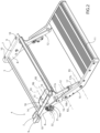
Figures 2-4 are perspective views of the retractable step according to three distinct operating configurations, -
Figures 5-7 are side views of a portion of the retractable step in the three operating configurations ofFigures 2-4 , -
Figure 8 is a perspective view of the retractable step inFigure 2 , from an opposite viewpoint, -
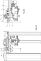
Figure 9 is a front view of a portion of the retractable step according to the operating configuration ofFigure 3 , -
Figure 10 is a section view along the plane identified by the line A-A inFigure 9 , -
Figure 11 is a section view along the plane identified by the line B-B inFigure 9 , -
Figure 12 is a front view of the portion ofFigure 9 according to the operating configuration of the retractable step ofFigure 4 , -
Figure 13 is a section view along the plane identified by the line C-C inFigure 12 , and -
Figure 14 is an exploded view of the retractable step according to the operating configuration ofFigure 2 . - In
Figure 1 , thereference number 1 indicates, as a whole, a vehicle, in particular a heavy vehicle and more in particular a camper. - The
vehicle 1 has a body 2, which internally defines a passenger compartment or cabin that can be accessed by a user. - Moreover, the
vehicle 1 comprises a door 3 that can be selectively opened to allow the user to access the passenger compartment or cabin. - Below or at the door 3, the
vehicle 1 comprises aretractable step 4 to facilitate a user's access to the interior of the passenger compartment or cabin through the door 3. - The
retractable step 4 has aframe 5 fixable to the body 2 or more specifically to a lower portion of the same. The latter faces a road surface relative to which thevehicle 1 is movable, in particular via a plurality ofwheels 6 of a known type. - In
Figure 1 , theretractable step 4 is indeed fastened to the lower portion of the body 2. - The
frame 5 comprises two portions respectively comprising or defined bycorresponding plates 7 arranged symmetrically with respect to a plane of symmetry transversal to thevehicle 1 or more precisely to a direction of travel or longitudinal axis of the same. - In the illustrated embodiment, the
step 4 has a preferably symmetrical design with respect to the aforementioned plane of symmetry, except for some potentially non-symmetrical aspects that can be mentioned in isolation, therefore the following description will be limited to describing only one side of thestep 4 with respect to the plane of symmetry, with the indication that the characteristics of the other side are substantially mirrored due to the symmetrical structure of thestep 4. Any exceptions will be specifically mentioned where appropriate or necessary. - The
plate 7 has aplate portion 8 which extends according to a, in particular vertical, direction, and aplate portion 9 which extends according to another direction transversal or more precisely orthogonal to the previous direction. In other words, theplate portions - The
plate portion 9 faces the lower portion of the body 2 and is provided withslots 10 to allow the anchoring of thestep 4 to the body 2, in particular via fastening elements of a known type and not illustrated, for example threaded elements such as bolts, lag screws and the like, or even potentially non-detachable fastening elements such as rivets, which pass through theslots 10 and couple to the lower portion of the body 2. - The
step 4 additionally comprises aplatform 11 to facilitate a user's access to the interior of thevehicle 1, an articulatedmechanism 12 carried by theframe 5 for moving theplatform 11 relative to theframe 5, amotor 13, and atransmission 14 configured to transmit a power delivered by themotor 13 to themechanism 12, such that themechanism 12 moves theplatform 11. - The
motor 13 and thetransmission 14 can be non-symmetrical with respect to the aforementioned plane of symmetry, so that they may also be located on only one side of thestep 4, as in the illustrated embodiment. - The
mechanism 12 preferably has a single degree of freedom, so that the position of theplatform 11 with respect to theframe 5 is determined by the value of a variable representative of said single degree of freedom, for example an angle of rotation around an axis, according to a biunivocal relationship. - The
mechanism 12 has at least two rods orlevers rod 15 is attached to theplatform 11, for example directly or via fastening elements. - The
rod 16 is generically coupled to both theframe 5 and to therod 15, so that therod 15 and thus theplatform 11 are also carried by theframe 5. More in particular, although not strictly necessarily, therod 16 has twoends frame 5 and to therod 15, in particular directly. - The
end 16a is rotatable with respect to theframe 5 around an axis R1, which therefore defines a hinge axis for therod 16. - The rotation angle of the
rod 16 around the axis R1 can define, for example, the variable representative of the single degree of freedom of themechanism 12. - The
rods rod 16 is arranged between theportion plate 8, or more generally theframe 5, and therod 15. - The
mechanism 12 is movable in order to arrange or move theplatform 11 between two configurations relative to thevehicle 1, for example two extreme and opposite configurations, with particular reference to the variable representative of the degree of freedom of themechanism 12. The two configurations comprise an extracted configuration (Figure 2 ), in which theplatform 11 protrudes laterally relative to the body 2, in particular below the door 3, to facilitate access to the passenger compartment or cabin. Moreover, the two configurations comprise a retracted configuration (Figures 3 ,4 ), in which theplatform 11 is below the body 2, i.e. does not protrude laterally relative to the body 2. - Moreover, the
mechanism 12 specifically comprises a further rod orlever 17 having twoends frame 5 and to theplatform 11 or to therod 15, for example directly. In the illustrated embodiment, theend 17b is directly hinged to therod 15. - In this manner, the
frame 5 together with therods mechanism 12 or defining themechanism 12. - The
ends frame 5 and to therod 15 around corresponding hinge axes R3, R5 parallel to the axes R2, R1. - Conveniently, the
plate portion 8 extends or is arranged between therods rods plate portion 8 or more generally theframe 5. - This applies in particular according to a direction parallel to the axis R1.
- Preferably, the
mechanism 12 comprises a stoppingelement 17c (Figure 8 ) that is fixed with respect to one or both of therods element 17c protrudes from one or both therods rod 17. - In the extracted configuration, the stopping
element 17c is arranged in contact with therod 17 in a position that prevents the movement of therod 17 towards the retracted configuration. Indeed, such a movement would exert a force on therods motor 13. - Therefore, the stopping
element 17c has the function of stopping themechanism 12 in the extracted configuration, even with a user's weight on theplatform 11. - In the extracted configuration, the
rod 17 is arranged between theplatform 11 and the stoppingelement 17c. - The
motor 13 comprises anouter casing 18 fastened to theframe 5, in particular at theplate portion 8, more in particular on the side of therod 17. - Therefore, preferably, the
plate portion 8 or more generally theframe 5 is arranged between thecasing 18 and therod 16, in particular in a direction parallel to the axis R1. - The
motor 13 is in particular an electric motor and can thus be powered with electric current, for example from a source in thevehicle 1, such as a battery or a generator. - Like all motors, the
motor 13 has a stator portion that is fixed with respect to thecasing 18 and a movable portion, in particular a rotor portion, i.e. that is rotatable around an axis with respect to the stator portion. The rotor portion and the stator portion are contained within thecasing 18. - The
motor 13 is configured to emit or deliver power, precisely by rotating the rotor portion. - The
transmission 14 comprises at least oneshaft 19 supported in a rotatable manner by theframe 5 around an axis, in particular parallel to and more in particular coinciding with the axis R1. - The
shaft 19 is coupled to themotor 13 or more precisely to its rotor portion in order to be driven into rotation by the power delivered by themotor 13, i.e. by virtue of the corresponding rotation of the rotor portion transmitted to theshaft 19 by suitable transmission means or devices. - In the present case, the
shaft 19 is coupled to themotor 13 or more precisely to the rotor portion via conjugate or splined profiles. In particular, theshaft 19 is provided with afirst portion 19a with a quadrilateral cross section coupled to acorresponding hub 13b of themotor 13. Thehub 13b is rotatable around the axis R1 by means of the power delivered by themotor 13. The rotation of the hub is thus transmitted directly to theshaft 19, so that theshaft 19 rotates rigidly together with the hub. - The
shaft 19 is supported by theframe 5 or more precisely by theplate portion 8 via a bearing, in particular defined by a sliding-friction bearing orbushing 20. - The
bushing 20 can be considered part of theframe 5 or of thetransmission 14. - The
bushing 20 has a radially innermost surface, which is radially in contact with a portion 19b of theshaft 19. The portion 19b preferably has a circular cross section. - Preferably, the
bushing 20 also has a radiallyoutermost surface 21 which supports the rotation of therod 16 around the axis R1. - Moreover, the
transmission 14 comprises a crank 22 coupled to theshaft 19, in particular so as to form a rotational couple with theshaft 19. Thecrank 22 is thus driven into rotation by theshaft 19 around the axis R1, i.e. the axis of theshaft 19 and the hub of themotor 13. - More precisely, the
crank 22 is fixed, at least rotationally, to theshaft 19, in particular via a coupling with conjugate or splined profiles between theshaft 19 and thecrank 22. - More in particular, the
shaft 19 comprises aportion 19c with a quadrilateral cross section coupled to a corresponding hub of thecrank 22. - In the illustrated embodiment, the
crank 22 has a substantially triangular shape. Here, the term substantially means that the corners of the triangular shape can also be rounded or joined together. In any case, the shape of thecrank 22 is not essential, although advantageous, so that it may be different from the one illustrated. - Conveniently, the
shaft 19 has a threadedend 19d. Theshaft 19, thelever 16, thecrank 22 are axially fastened or packed together via anut 25 screwed to the threadedportion 19d until it is tightened against thecrank 22. - According to an aspect of the invention, the crank 22 can be releasably fastened to the
lever 16 at an eccentric point or area of the crank 22 relative to the axis R1, i.e. to the axis of rotation of thecrank 22. In other words, thestep 4 comprises afastening assembly 23 configured to fasten the crank 22 to therod 16 in a releasable manner and at an axis R6 parallel to the axis R1 and distinct from the latter. - The axis R6 performs a motion of revolution around the axis R1 in response to a rotation of the
crank 22 around the axis R1. - The term releasable is understood here to mean that the components fastened via the
fastening assembly 23 can be disconnected or disengaged from each other by detaching thefastening assembly 23 without compromising the operation of thefastening assembly 23 or of thestep 4, i.e. without causing a permanent deformation or breakage of thefastening assembly 23 or of the components fastened via thefastening assembly 23. - Preferably, the
fastening assembly 23 is manually releasable, i.e. without the aid of tools or solely by means the user's limbs. - More specifically, the
fastening assembly 23 comprises apin 24 configured to be arranged in an insertion position, in which thepin 24 is inserted through thecrank 22 and therod 16 along the axis R6. - Therefore, firstly, the
crank 22 and therod 16 haverespective holes - In particular, at least the
hole 52 of thecrank 22 is a through hole, while thehole 53 of therod 16 is preferably a through hole, although not necessarily. - In the insertion position, the
pin 24 is inserted along the axis R6 through both of theholes pin 24 engages substantially the entire radial dimension of theholes - In this manner, i.e. in the insertion position, the
pin 24 is configured to transmit the rotation of thecrank 22 to therod 16 around the axis R1. - Moreover, the
fastening assembly 23 comprises releasable fastening devices configured to fasten thepin 24 in the insertion position in a releasable manner. - Indeed, without these fastening devices or with the fastening devices released or detached, the
pin 24 may be extracted axially from theholes pin 24 from the insertion position would disengage the crank 22 from therod 16 and thus, consequently, themotor 13 from themechanism 12. - In more detail, the fastening devices comprise a
bracket 30, afirst fastening device 31, and asecond fastening device 32. - The
bracket 30 is configured to be crossed by thepin 24 along the axis R6 in the insertion position. In other words, thebracket 30 has a throughhole 33 adapted for the passage of thepin 24 in the insertion position along the axis R6. - In particular, the
bracket 30 comprises or is defined by a plate to be arranged with the direction of its thickness parallel to the axis R6. The axis of thehole 33 is parallel to the direction of the thickness of the plate. - The
fastening device 31 is configured to secure thebracket 30 and thepin 24 to each other in a releasable manner, with thepin 24 passing through thebracket 30 in the insertion position, i.e. passing through thebracket 30, thecrank 22, and therod 16 along the axis R6. - The
fastening device 32 is configured to fasten thebracket 30 to the crank 22 in a releasable manner. - In this manner, the
pin 24 can be fastened axially along the axis R6 in the insertion position with the reciprocal fastening of thebracket 30 and of thepin 24 in the insertion position via thefastening device 31 and, contemporarily, of thebracket 30 to the crank 22 via thefastening device 32. - In this configuration, which can be defined as an operatimg configuration of the
step 4, thepin 24 is not extractable axially from the holes of thecrank 22 and therod 16, so that thecrank 22 is forced to rotate together with therod 16 around the axis R1, so that thetransmission 14 effectively transmits the power of themotor 13 to themechanism 12. - Here, i.e. when the
fastening devices bracket 30 to thepin 24 in the insertion position and thebracket 30 to the crank 22, thecrank 22 is arranged between thebracket 30 and therod 16, in particular along the axis R6 or the axis R1. More in particular, thecrank 22 is interposed directly between thebracket 30 and therod 16. - Preferably, in the insertion position, the
pin 24 comprises anabutment portion 35 configured to rest against thebracket 30 along the axis R6. Specifically, theabutment portion 35 rests axially against thebracket 30 when thepin 24 is fastened to the latter in the insertion position via thefastening device 31. - Moreover, the
pin 24 has aninsertion portion 36 extending axially, i.e. along the axis R6 in the insertion position, from theabutment portion 35; theinsertion portion 36 is configured to pass through thebracket 30 in a through manner along the axis R6 with thepin 24 in the insertion position and with theabutment portion 35 resting against thebracket 30. In other words, here, the insertion portion extends from theabutment portion 35 through thehole 33 of thebracket 30, thus protruding axially relative to saidbracket 30. - In practice, the
abutment portion 35 and theinsertion portion 36 are axially adjacent to each other and have a radial dimension, i.e. specifically a diameter, respectively greater and smaller than that of thehole 33, so that theabutment portion 35 abuts thebracket 30 when theinsertion portion 36 passes through thebracket 30 via thehole 33. - The
insertion portion 36 has anexternal thread 37, in particular on the part that is to be arranged so as to be axially protruding relative to thebracket 30. - Conveniently, the
fastening device 31 comprises aknob 38, which is internally threaded and configured to mate with theexternal thread 37 of thepin 24 to tighten theabutment portion 35 against thebracket 30, thus fastening thepin 24 to thebracket 30. - In practice, the
knob 38 can be screwed onto theexternal thread 37 until it is tightened against thebracket 30. Here, theabutment portion 35 is tightened on thebracket 30 axially. - Preferably, the
crank 22 comprises abase portion 40 and abody 41 protruding from thebase portion 40 along an axis R7 parallel to the axis R6 or the axis R1. - In more detail, the
body 41 is a pin provided with agroove 41a at one end; in particular, thegroove 41a is annular around the axis R7. - Specifically, the
base portion 40 is arranged between thebody 41 and therod 16, along the axis R7. In other words, thebody 41 protrudes from thebase portion 40 on the side opposite theshaft 19. - The
bracket 30 is configured to be passed through by thebody 41 along the axis R7. In other words, thebracket 30 has a throughhole 42 which can receive thebody 41 along the axis R7. - The distance between the
holes bracket 30 is equal to the distance between the axes R6, R7. - Preferably, the
fastening device 32 comprises aclip 43, for example of a known type, configured to secure thebracket 30 to thebody 41 via a snap-fit coupling, in particular with thebody 41 passing through thebracket 30 or extending through thehole 42 along the axis R7. - In particular, the
clip 43 comprises a leaf folded on itself around a folding axis so as to have two leaf portions which face each other and which can be brought together by bending the folding area of the leaf around the folding axis by pushing one leaf portion towards the other leaf portion. - The leaf portions have respective slots arranged opposite each other; moreover, the leaf portions are elastically deformable so that the relative slots expand elastically when forced against the
body 41 along the axis R7 towards thebase portion 40 to be passed through by saidbody 41. - Indeed, the slots can slide on the
body 41 along the axis R7 with interference, in particular caused by the elastic reactions of the leaf portions. - The elastic reactions are directed radially with respect to the axis R7.
- Moreover, the leaf portions are configured to constrict at the
groove 41a after having been expanded by forcing thebody 41 through the openings along the axis R7, thus snap-fitting onto thebody 41 at thegroove 41a. - The
clip 43 can be disengaged from thebody 41 by manually pushing one leaf portion towards the other leaf portion, so as to cause a bending of the leaf around the folding axis and a release of the leaf portions from thegroove 41a. In this manner, the slots can be expanded by applying an extraction force to the leaf portions against thebody 41 along the axis R7 in a direction away from thebase portion 40. Theclip 43 can thus be slipped off thebody 41. - The
bracket 30 can be passed through by thebody 41 and arranged between theclip 43 and thecrank 22 along the axis R7. In this manner, thebracket 30 is locked axially between theclip 43 and thecrank 22. - Preferably, the
rod 17 forms, potentially together with theplate portion 8, when the latter is present, afastening interface 47 when theplatform 11 is arranged in the retracted configuration, which is suitable for preventing thestep 4 from protruding laterally relative to thevehicle 1. - The
fastening interface 47 may not be symmetrical with respect to the aforementioned plane of symmetry. - The
fastening interface 47 comprises at least oneattachment portion 48, for example analogous to thebody 41 in terms of its design and/or function, carried in a fixed manner by therod 17. - The
attachment portion 48 is configured to cooperate with thefastening device 32 to fasten thebracket 30 to therod 17 or more precisely to theattachment portion 48. - The mode of fastening the
bracket 30 to theattachment portion 48 via thefastening device 32 can be analogous to the one already described for fastening thebracket 30 to thebody 41. - Moreover, the
fastening interface 47 can comprise ahole 49 on one between theplate portion 8 and therod 17 for accommodating or receiving thepin 24 in a further insertion position; here, in the further insertion position, thepin 24 can then be fastened to thebracket 30 via thefastening device 31. - The
hole 49 has an axis R9, while theattachment portion 48 extends along an axis R10. - The distance between the
hole 49 and theattachment portion 48, or more precisely the distance between the axes R9, R10, is equal to the distance between theholes bracket 30. - Preferably, the
fastening interface 47 can comprise anadditional hole 50 forming a pair of holes with thehole 49. - The
hole 50 is obtained on the other one between theplate portion 8 and therod 17 with respect to thehole 49. - Moreover, in the retracted configuration, the
hole 50 is aligned with thehole 49 along the axis R9, which is parallel to the axis R6 or the axis R1. - The
holes pin 24 contemporarily in the further insertion position. Here, i.e. in the further insertion position, thepin 24 can be secured to thebracket 30 via thefastening device 31. - The securing of the
pin 24 to thebracket 30 in the further insertion position, i.e. through theholes pin 24 to thebracket 30 in the insertion position described in the foregoing, i.e. passing through the holes in thecrank 22 and in therod 16. - When the
pin 24 is secured to thebracket 30 in the further insertion position through theholes bracket 30 to theattachment portion 48 via thefastening device 32 results in the fastening of therod 17 to theframe 5 or more precisely to theplate portion 8. - This corresponds to the blocking of the
mechanism 12 with theplatform 11 in the retracted configuration. - Indeed, the single degree of freedom of the
mechanism 12 is eliminated here. -
Figure 4 shows an emergency configuration of thestep 4, in which theplatform 11 is in the retracted configuration, and in which therod 17 is fastened to theplate portion 8 via thefastening devices - A transition from the operating configuration (for example illustrated in
Figure 2 ) to the emergency configuration of thestep 4 can comprise the following steps: - detaching or releasing the
fastening devices pin 24 is fastened in the insertion position through the crank 22 (Figure 2 ), - sliding the
pin 24 out of the holes in thecrank 22 and therod 16, - placing the
platform 11 in the retracted configuration via themechanism 12, for example manually, and - fastening the
pin 24 to thebracket 30 in the further insertion position through theholes fastening device 31, and - fastening the
bracket 30 to theattachment portion 48 via the fastening device 32 (Figure 4 ). - The advantages of the
retractable step 4 according to the invention are evident from the foregoing. - Indeed, the
fastening devices - In particular, the
knob 38 and theclip 43 are realized ergonomically. - Moreover, the
same devices mechanism 12 with theplatform 11 in the retracted configuration in a simple and intuitive manner. - In addition, the arrangement of the
plate portion 8 or of theframe 5 between thecrank 22 and therod 17 minimizes the possibility of hindering the operation of themechanism 12. - Finally, it is clear that modifications and variations can be made to the
retractable step 4 according to the present invention without thereby departing from the protective scope defined by the claims.
Claims (10)
- Retractable step (4) for a vehicle (1), the retractable step (4) comprising:- at least one platform (11) to facilitate a user's access to the interior of the vehicle (1),- a frame (5) fixable to a lower body portion (2) of the vehicle (1),- an articulated mechanism (12) comprising at least a first rod (15) fastened to the platform and a second rod (16) having a first and a second end (16a, 16b) hinged to the first rod (15) and the frame (5), respectively,- a motor (13) carried by the frame (5) and configured to deliver power,- a transmission (14) configured to transmit the power delivered by the motor (13) to the articulated mechanism (12), such that the articulated mechanism (12) moves the platform (11) relative to the frame (5),wherein the transmission (14) comprises- a shaft (19) rotatably supported by the frame (5) around a first axis (R1) and coupled to the motor (13) to be driven into rotation by said power,- a crank (22) rotationally coupled to the shaft (19) to be driven into rotation by the shaft (19) around the first axis (R1),- fastening means (23) configured to fastened the crank (22) to the second rod (16) in a releasable manner at a second axis (R6) parallel to and distinct from the first axis (R1).
- Retractable step according to claim 1, wherein the fastening means (23) comprises- a pin (24) configured to be arranged in an insertion position, in which the pin (24) is inserted through the crank (22) and the second rod (16) along a second axis (R2) parallel to the first axis (R1), and- fastening devices (30, 31, 32) configured to fasten the pin (24) in the insertion position in a releasable manner.
- Retractable step according to claim 2, wherein the fastening devices (31, 32) comprise- a bracket (30) configured to be passed through along the second axis by the pin in the insertion position,- a first fastening device (31) configured to releasably fasten the bracket (30) and the pin (24) passing through the bracket (30) in the insertion position to each other, and- a second fastening device (32) configured to fasten the bracket (30) to the crank (22) in a releasable manner.
- Retractable step according to claim 3, wherein the crank (22) is arranged between the bracket (30) and the second rod (16) when the first and second fastening devices (31, 32) respectively fasten the bracket (30) to the pin (24) in the insertion position and the bracket (30) to the crank (22).
- Retractable step according to claim 3 or 4, wherein the pin (24) in the insertion position comprises an abutment portion (35) configured to rest against the bracket (30) along the second axis (R6), and an insertion portion (36) extending axially from the abutment portion (35) and configured to pass through the bracket (30) in a through manner along the second axis (R6) when the abutment portion (35) rest against the bracket (30), the insertion portion (36) having an external thread (37), whereby the first fastening device (31) comprises a knob (38) internally threaded and configured to mate with the external thread (37) to tighten the abutment portion (35) against the bracket (30), thereby fastening the pin (24) to the bracket (30).
- Retractable step according to any one of claims 3 to 5, wherein the crank (22) comprises a base portion (40) and a body (41) protruding from the base portion (40) along a third axis (R7) parallel to the second axis (R6), wherein the second fastening device (32) comprises a clip (43) configured to secure the bracket (30) to the protruding body (41) via a snap fit coupling.
- Retractable step according to any one of the preceding claims, wherein the articulated mechanism (12) comprises a third rod (17) having a third and a fourth end (17a, 17b) respectively hinged to the frame (5) and to one between the first rod (15) and the platform (11).
- Retractable step according to claim 7, wherein the frame comprises a first plate portion (8) arranged between the second rod (16) and the third rod (17) according to a direction parallel to the first axis (R1).
- Retractable step according to claim 7, when claim 6 depends on one of claims 2 to 5, wherein the third rod (17) forms together with the first plate portion (8) a fastening interface (47) when the platform (11) is arranged via the articulated mechanism (12) in a specific retracted configuration suitable for preventing the step (4) from protruding laterally relative to the vehicle (1) when the step (4) is mounted on the vehicle (1), the fastening interface (47) comprising- a pair of holes (49, 50) aligned with each other along a fourth axis (R9) parallel to the second axis (R6) and respectively obtained on the first plate portion (8) and the third rod (17) so that they can both receive the pin (24) contemporarily, such that the pin (24) can be therein fastened to the bracket (30) via the first fastening device (31), and- an attachment portion (48) carried in a fixed manner by the third rod (17) and configured to cooperate with the second fastening device (32) to fasten the bracket (30) to the third rod (17), thereby locking the articulated mechanism (12) with the platform (11) in said retracted configuration.
- Vehicle (1) comprising a body (2), a passenger compartment or interior cabin carried by the body (2), a door (3) for access to the passenger compartment or interior cabin, and a retractable step (4) according to any of the preceding claims, the retractable step (4) being carried by the body (2) below the door (3).
Applications Claiming Priority (1)
| Application Number | Priority Date | Filing Date | Title |
|---|---|---|---|
| IT102023000003054A IT202300003054A1 (en) | 2023-02-22 | 2023-02-22 | MOTORIZED RETRACTABLE STEP FOR A VEHICLE |
Publications (1)
| Publication Number | Publication Date |
|---|---|
| EP4420931A1 true EP4420931A1 (en) | 2024-08-28 |
Family
ID=86332405
Family Applications (1)
| Application Number | Title | Priority Date | Filing Date |
|---|---|---|---|
| EP24158818.5A Withdrawn EP4420931A1 (en) | 2023-02-22 | 2024-02-21 | Motorized retractable step for a vehicle |
Country Status (2)
| Country | Link |
|---|---|
| EP (1) | EP4420931A1 (en) |
| IT (1) | IT202300003054A1 (en) |
Cited By (1)
| Publication number | Priority date | Publication date | Assignee | Title |
|---|---|---|---|---|
| RU235520U1 (en) * | 2025-04-30 | 2025-07-04 | Общество с ограниченной ответственностью "Автомобильный завод "НАЗ" | Retractable vehicle step |
Citations (3)
| Publication number | Priority date | Publication date | Assignee | Title |
|---|---|---|---|---|
| EP1445151A1 (en) * | 2003-02-06 | 2004-08-11 | FIAT AUTO S.p.A. | An electromechanically controlled retractable step for a vehicle |
| KR20180076873A (en) * | 2016-12-28 | 2018-07-06 | 인천대학교 산학협력단 | Automatic folding type running board |
| EP3604037A1 (en) * | 2018-08-01 | 2020-02-05 | Project 2000 S.r.l. | Retractable step |
-
2023
- 2023-02-22 IT IT102023000003054A patent/IT202300003054A1/en unknown
-
2024
- 2024-02-21 EP EP24158818.5A patent/EP4420931A1/en not_active Withdrawn
Patent Citations (3)
| Publication number | Priority date | Publication date | Assignee | Title |
|---|---|---|---|---|
| EP1445151A1 (en) * | 2003-02-06 | 2004-08-11 | FIAT AUTO S.p.A. | An electromechanically controlled retractable step for a vehicle |
| KR20180076873A (en) * | 2016-12-28 | 2018-07-06 | 인천대학교 산학협력단 | Automatic folding type running board |
| EP3604037A1 (en) * | 2018-08-01 | 2020-02-05 | Project 2000 S.r.l. | Retractable step |
Cited By (1)
| Publication number | Priority date | Publication date | Assignee | Title |
|---|---|---|---|---|
| RU235520U1 (en) * | 2025-04-30 | 2025-07-04 | Общество с ограниченной ответственностью "Автомобильный завод "НАЗ" | Retractable vehicle step |
Also Published As
| Publication number | Publication date |
|---|---|
| IT202300003054A1 (en) | 2024-08-22 |
Similar Documents
| Publication | Publication Date | Title |
|---|---|---|
| KR101536159B1 (en) | Locking mechanism and housing of vehicle | |
| WO2000078573A9 (en) | Modular extending mirror | |
| US8469312B2 (en) | Integrated maintenance step on helicopter fuselage | |
| CN211818786U (en) | Automobile front cover lock unlocking device and automobile | |
| US20030052209A1 (en) | Belt retractor | |
| JP6211647B2 (en) | Complete walk-in device | |
| CN112172685B (en) | Retainer with frame | |
| EP4420931A1 (en) | Motorized retractable step for a vehicle | |
| CN111114403B (en) | Automobile seat | |
| JP3268837B2 (en) | Automotive roof equipment | |
| US6971489B2 (en) | Removable motor brake for use with vehicle slide out | |
| EP3158153B1 (en) | Tensioning tool | |
| CN112824144A (en) | Backrest locking device and backrest arrangement for a motor vehicle | |
| US11505050B2 (en) | Emergency mechanism for lid kinematic device | |
| AU2018206778B2 (en) | Wheel reversing mechanism and cart frame | |
| CN215245314U (en) | Self-locking folder | |
| CN210191569U (en) | Brake equipment and children's shallow | |
| RU186253U1 (en) | Device to prevent unauthorized use of the car by a pinless steering lock | |
| CA3011778C (en) | Rotational sliding bearing | |
| JP2022515818A (en) | Locking systems for in-vehicle freight transport systems, and vehicles with such locking systems | |
| CN112572498A (en) | Escape ladder, rail vehicle and rail transit system | |
| CN215922002U (en) | All-terrain vehicle | |
| AU2024242279A1 (en) | Torsion spring tensioning tool | |
| US2979966A (en) | Emergency release of power-drive drawer | |
| EP1111166A1 (en) | Key unit for a door of a motor vehicle |
Legal Events
| Date | Code | Title | Description |
|---|---|---|---|
| PUAI | Public reference made under article 153(3) epc to a published international application that has entered the european phase |
Free format text: ORIGINAL CODE: 0009012 |
|
| STAA | Information on the status of an ep patent application or granted ep patent |
Free format text: STATUS: THE APPLICATION HAS BEEN PUBLISHED |
|
| AK | Designated contracting states |
Kind code of ref document: A1 Designated state(s): AL AT BE BG CH CY CZ DE DK EE ES FI FR GB GR HR HU IE IS IT LI LT LU LV MC ME MK MT NL NO PL PT RO RS SE SI SK SM TR |
|
| STAA | Information on the status of an ep patent application or granted ep patent |
Free format text: STATUS: THE APPLICATION IS DEEMED TO BE WITHDRAWN |
|
| 18D | Application deemed to be withdrawn |
Effective date: 20250301 |