EP4420916A2 - Work vehicle - Google Patents
Work vehicle Download PDFInfo
- Publication number
- EP4420916A2 EP4420916A2 EP23216006.9A EP23216006A EP4420916A2 EP 4420916 A2 EP4420916 A2 EP 4420916A2 EP 23216006 A EP23216006 A EP 23216006A EP 4420916 A2 EP4420916 A2 EP 4420916A2
- Authority
- EP
- European Patent Office
- Prior art keywords
- battery
- temperature
- discharge
- cooling
- charging
- Prior art date
- Legal status (The legal status is an assumption and is not a legal conclusion. Google has not performed a legal analysis and makes no representation as to the accuracy of the status listed.)
- Pending
Links
- 238000001816 cooling Methods 0.000 claims description 87
- 238000001514 detection method Methods 0.000 claims description 61
- 239000003921 oil Substances 0.000 claims description 24
- 239000010720 hydraulic oil Substances 0.000 claims description 21
- 238000011144 upstream manufacturing Methods 0.000 claims description 3
- 230000005540 biological transmission Effects 0.000 description 19
- 230000007935 neutral effect Effects 0.000 description 15
- 238000007599 discharging Methods 0.000 description 14
- 239000000498 cooling water Substances 0.000 description 13
- 230000002159 abnormal effect Effects 0.000 description 2
- 230000015556 catabolic process Effects 0.000 description 2
- 239000002826 coolant Substances 0.000 description 2
- 238000006731 degradation reaction Methods 0.000 description 2
- 238000010586 diagram Methods 0.000 description 2
- HEZMWWAKWCSUCB-PHDIDXHHSA-N (3R,4R)-3,4-dihydroxycyclohexa-1,5-diene-1-carboxylic acid Chemical compound O[C@@H]1C=CC(C(O)=O)=C[C@H]1O HEZMWWAKWCSUCB-PHDIDXHHSA-N 0.000 description 1
- 238000006243 chemical reaction Methods 0.000 description 1
- 230000008878 coupling Effects 0.000 description 1
- 238000010168 coupling process Methods 0.000 description 1
- 238000005859 coupling reaction Methods 0.000 description 1
- 230000007423 decrease Effects 0.000 description 1
- 230000002706 hydrostatic effect Effects 0.000 description 1
- 238000013021 overheating Methods 0.000 description 1
Images



Classifications
-
- B—PERFORMING OPERATIONS; TRANSPORTING
- B60—VEHICLES IN GENERAL
- B60L—PROPULSION OF ELECTRICALLY-PROPELLED VEHICLES; SUPPLYING ELECTRIC POWER FOR AUXILIARY EQUIPMENT OF ELECTRICALLY-PROPELLED VEHICLES; ELECTRODYNAMIC BRAKE SYSTEMS FOR VEHICLES IN GENERAL; MAGNETIC SUSPENSION OR LEVITATION FOR VEHICLES; MONITORING OPERATING VARIABLES OF ELECTRICALLY-PROPELLED VEHICLES; ELECTRIC SAFETY DEVICES FOR ELECTRICALLY-PROPELLED VEHICLES
- B60L1/00—Supplying electric power to auxiliary equipment of vehicles
- B60L1/003—Supplying electric power to auxiliary equipment of vehicles to auxiliary motors, e.g. for pumps, compressors
-
- B—PERFORMING OPERATIONS; TRANSPORTING
- B60—VEHICLES IN GENERAL
- B60L—PROPULSION OF ELECTRICALLY-PROPELLED VEHICLES; SUPPLYING ELECTRIC POWER FOR AUXILIARY EQUIPMENT OF ELECTRICALLY-PROPELLED VEHICLES; ELECTRODYNAMIC BRAKE SYSTEMS FOR VEHICLES IN GENERAL; MAGNETIC SUSPENSION OR LEVITATION FOR VEHICLES; MONITORING OPERATING VARIABLES OF ELECTRICALLY-PROPELLED VEHICLES; ELECTRIC SAFETY DEVICES FOR ELECTRICALLY-PROPELLED VEHICLES
- B60L58/00—Methods or circuit arrangements for monitoring or controlling batteries or fuel cells, specially adapted for electric vehicles
- B60L58/10—Methods or circuit arrangements for monitoring or controlling batteries or fuel cells, specially adapted for electric vehicles for monitoring or controlling batteries
- B60L58/12—Methods or circuit arrangements for monitoring or controlling batteries or fuel cells, specially adapted for electric vehicles for monitoring or controlling batteries responding to state of charge [SoC]
- B60L58/14—Preventing excessive discharging
-
- B—PERFORMING OPERATIONS; TRANSPORTING
- B60—VEHICLES IN GENERAL
- B60L—PROPULSION OF ELECTRICALLY-PROPELLED VEHICLES; SUPPLYING ELECTRIC POWER FOR AUXILIARY EQUIPMENT OF ELECTRICALLY-PROPELLED VEHICLES; ELECTRODYNAMIC BRAKE SYSTEMS FOR VEHICLES IN GENERAL; MAGNETIC SUSPENSION OR LEVITATION FOR VEHICLES; MONITORING OPERATING VARIABLES OF ELECTRICALLY-PROPELLED VEHICLES; ELECTRIC SAFETY DEVICES FOR ELECTRICALLY-PROPELLED VEHICLES
- B60L58/00—Methods or circuit arrangements for monitoring or controlling batteries or fuel cells, specially adapted for electric vehicles
- B60L58/10—Methods or circuit arrangements for monitoring or controlling batteries or fuel cells, specially adapted for electric vehicles for monitoring or controlling batteries
- B60L58/24—Methods or circuit arrangements for monitoring or controlling batteries or fuel cells, specially adapted for electric vehicles for monitoring or controlling batteries for controlling the temperature of batteries
- B60L58/26—Methods or circuit arrangements for monitoring or controlling batteries or fuel cells, specially adapted for electric vehicles for monitoring or controlling batteries for controlling the temperature of batteries by cooling
-
- B—PERFORMING OPERATIONS; TRANSPORTING
- B60—VEHICLES IN GENERAL
- B60L—PROPULSION OF ELECTRICALLY-PROPELLED VEHICLES; SUPPLYING ELECTRIC POWER FOR AUXILIARY EQUIPMENT OF ELECTRICALLY-PROPELLED VEHICLES; ELECTRODYNAMIC BRAKE SYSTEMS FOR VEHICLES IN GENERAL; MAGNETIC SUSPENSION OR LEVITATION FOR VEHICLES; MONITORING OPERATING VARIABLES OF ELECTRICALLY-PROPELLED VEHICLES; ELECTRIC SAFETY DEVICES FOR ELECTRICALLY-PROPELLED VEHICLES
- B60L2200/00—Type of vehicles
- B60L2200/40—Working vehicles
-
- B—PERFORMING OPERATIONS; TRANSPORTING
- B60—VEHICLES IN GENERAL
- B60L—PROPULSION OF ELECTRICALLY-PROPELLED VEHICLES; SUPPLYING ELECTRIC POWER FOR AUXILIARY EQUIPMENT OF ELECTRICALLY-PROPELLED VEHICLES; ELECTRODYNAMIC BRAKE SYSTEMS FOR VEHICLES IN GENERAL; MAGNETIC SUSPENSION OR LEVITATION FOR VEHICLES; MONITORING OPERATING VARIABLES OF ELECTRICALLY-PROPELLED VEHICLES; ELECTRIC SAFETY DEVICES FOR ELECTRICALLY-PROPELLED VEHICLES
- B60L2240/00—Control parameters of input or output; Target parameters
- B60L2240/40—Drive Train control parameters
- B60L2240/54—Drive Train control parameters related to batteries
- B60L2240/545—Temperature
Definitions
- the present invention relates to a work vehicle.
- JP 2013-141875A there are work vehicles (electric tractors) equipped with an electric actuator (travel motor, work motor), and a battery (battery, auxiliary battery) that supplies drive power to the electric actuator.
- electric actuator travel motor, work motor
- battery battery, auxiliary battery
- the invention provides a work vehicle that is able to perform work, using power efficiently output by a battery, even if the battery is cold before starting work.
- a work vehicle according to the invention comprises:
- the battery when the battery is being charged before starting work, the battery can be discharged by the discharge operation apparatus to heat the battery due to the discharging, and thus, even if the battery is cold before starting work, at the time of performing work, the battery is warmer than before starting work and the work vehicle is able to use power efficiently output by the battery.
- the above configuration preferably further includes a hydraulic pump connected to a hydraulic actuator via an operating oil path and configured to supply hydraulic oil to the hydraulic actuator, an operating valve provided in the operating oil path and configured to control the hydraulic actuator, a relief oil path connected to a portion of the operating oil channel upstream of the operating valve, and an electric motor configured to drive the hydraulic pump, and the discharge operation apparatus preferably causes the battery to discharge by connecting the battery to the electric motor such that power is supplied to the electric motor from the battery.
- the electric motor is driven by power discharged by the battery that is caused to discharge by the discharge operation apparatus, and the hydraulic pump is driven by the electric motor to supply hydraulic oil to the operating oil path.
- the operating valve is in the neutral position, and hydraulic oil supplied to the operating oil channel flows into the relief oil channel and returns to the tank through the relief oil channel.
- the hydraulic oil then increases in temperature and decreases in viscosity, allowing the hydraulic oil to flow more easily. In other words, at the time of performing work, the hydraulic oil flows more easily toward the hydraulic actuator compared to before charging the battery, and operation of the hydraulic actuator is facilitated.
- the above configuration preferably further includes a charging detection mechanism configured to detect charging of the battery, and the discharge operation apparatus preferably includes a discharge control section configured to cause the battery to discharge during charging, based on detection information of the charging detection mechanism.
- the discharge control section controls the discharge operation apparatus based on detection information of the charging detection mechanism, and the battery is caused to discharge by the discharge operation apparatus, thus enabling the temperature of the battery to be easily increased without the extra time and effort involved in discharging the battery.
- the above configuration preferably further includes a battery temperature detection mechanism configured to detect a temperature of the battery, and the discharge control section preferably causes the battery to discharge during charging, in response to a battery temperature detected by the battery temperature detection mechanism being lower than a set battery temperature, and does not cause the battery to discharge during charging, in response to the detected battery temperature being higher than or equal to the set battery temperature.
- a battery temperature detection mechanism configured to detect a temperature of the battery
- the discharge control section preferably causes the battery to discharge during charging, in response to a battery temperature detected by the battery temperature detection mechanism being lower than a set battery temperature, and does not cause the battery to discharge during charging, in response to the detected battery temperature being higher than or equal to the set battery temperature.
- the discharge control section operates the battery to a non-discharge state and the battery stops discharging, thus enabling the battery to be prevented from overheating due to the discharging, by appropriately setting the set battery temperature.
- the above configuration preferably further includes a power device connected to the battery, a cooling apparatus configured to cool the power device, a device temperature detection mechanism configured to detect a temperature of the power device, and a cooling control apparatus configured to control operation of the cooling apparatus based on detection information of the device temperature detection mechanism, and the cooling control apparatus preferably controls the cooling apparatus to operate, in response to a device temperature detected by the device temperature detection mechanism being higher than or equal to a set device temperature, and controls the cooling apparatus to stop operation, in response to the detected device temperature being lower than the set device temperature.
- the cooling control apparatus operates the cooling apparatus based on the device temperature detected by the device temperature detection mechanism and the set device temperature, and the power device is cooled while ensuring that the temperature of the power device does not rise to higher than or equal to the set device temperature or fall to lower than the set device temperature, thus enabling failure or performance degradation due to a rise or fall in the temperature of the power device to be prevented.
- the power device is an inverter.
- the above configuration preferably further includes an electric device connected to the battery, and a device cooling apparatus configured to cool the electric device.
- the electric device can be cooled by the device cooling apparatus, thus enabling failure due to an increase in temperature of the electric device to be avoided by preventing an abnormal increase in temperature caused by driving the electric device, for example.
- the above configuration preferably further includes a battery cooling apparatus configured to cool the battery.
- the battery can be cooled by the battery cooling apparatus, thus enabling an abnormal increase in temperature caused by discharging the battery, for example, to be avoided.
- the direction of the arrow F shown in FIG. 1 is “the body front side”
- the direction of the arrow B shown in FIG. 1 is “the body back side”
- the direction of the arrow U shown in FIG. 1 is “the body up side”
- the direction of the arrow D shown in FIG. 1 is “the body down side”
- the direction of the front side of the sheet of FIG. 1 is “body left side”
- the direction of the back side of the sheet of FIG. 1 is “body right side” in relation to the travel body of an electric tractor (example of "work vehicle”).
- the electric tractor includes a travel body 3 having a pair of left and right front wheels 1 and a pair of left and right back wheels 2.
- the pair of left and right front wheels 1 are steerable and drivable.
- the pair of left and right back wheels 2 are drivable.
- the travel body 3 includes a body frame 4 that is provided with a front frame 5 constituting a front portion of the body frame 4 and a transmission case 6 coupled to a back portion of the front frame 5 and constituting a back portion of the body frame 4.
- a motive section 8 that includes a travel electric motor 7 serving as an electric actuator that drives the front wheels 1 and the back wheels 2.
- a driving section 9 in which an operator rides.
- the driving section 9 is provided with a driver's seat 10, a steering wheel 11 for steering the front wheels 1, and a ROPS 12.
- a link mechanism 13 for coupling any of various work apparatuses such as a rotary tiller (not shown) in such a manner as to be raisable and lowerable, and a power takeoff shaft 14 that takes work power from inside the transmission case 6 and transmits the power to the coupled work apparatus.
- the motive section 8 includes a battery 15 that supplies drive power to the travel electric motor 7, and an inverter 16 that converts DC power from the battery 15 into AC power and supplies the AC power to the travel electric motor 7.
- the battery 15 is supported by a battery mount 5b provided in an upper portion of the front frame 5.
- the inverter 16 is disposed backward of the battery 15.
- the travel electric motor 7 is supported by the front frame 5 in such a manner as to be disposed between left and right side frame portions 5a of the front frame 5 downward of the battery 15 and the inverter 16.
- Driving of the back wheels 2 by the travel electric motor 7 is made possible, by the travel electric motor 7 being driven by power supplied from the battery 15 via the inverter 16, the output of the travel electric motor 7 being input via a rotation shaft 17 to a hydrostatic continuously variable transmission 6a provided in a front portion of the transmission case 6, and the output of the continuously variable transmission 6a being transmitted to a gear transmission (not shown) provided inside the transmission case 6 and transmitted to the back wheels 2 from the gear transmission.
- Driving of the front wheels 1 by the travel electric motor 7 is made possible, by the power transmitted from the continuously variable transmission 6a to the gear transmission being input to a front wheel drive case 19 via a rotation shaft 18 extending toward the body front side from the transmission case 6.
- the link mechanism 13 is provided with a pair of left and right lower links 20 extending backward from a lower portion of the transmission case 6 in such a manner as to be swingable up and down, a top link 21 extending backward from an upper portion of the transmission case 6 in such a manner as to be swingable up and down, a pair of left and right lift arms 22 supported in such a manner as to be swingable up and down in an upper portion of the transmission case 6, a left lift rod 23 that couples the left lift arm 22 and the left lower link 20, and a right lift rod 23 that couples the right lift arm 22 and the right lower link 20.
- the work apparatus is coupled to the transmission case 6 in such a manner as to be raisable and lowerable due to the left and right lower links 20 and the top link 21 being coupled to the work apparatus. Due to the right and left lift arms 22 being raised and lowered, the left lower link 20 is raised and lowered by the left lift arm 22 via the left lift rod 23 and the right lower link 20 is raised and lowered by the right lift arm 22 via the right lift rod 23, resulting in the work apparatus being raised and lowered with respect to the travel body.
- a lift cylinder 24 serving as a hydraulic actuator coupled to a rotary support shaft 22a of the left and right lift arms 22, and in an upper portion of the transmission case 6 are provided a hydraulic pump 25 that supplies hydraulic oil to the lift cylinder 24 and an electric motor 26 that drives the hydraulic pump 25, enabling the link mechanism 13 to be raised and lowered.
- the hydraulic pump 25 and the lift cylinder 24 are connected via an operating oil path 27, and the operation oil path 27 is provided with an operating valve 28 that controls the lift cylinder 24.
- the operating oil path 27 has a relief oil path 29 connected thereto upstream of the operating valve 28.
- the hydraulic pump 25 is driven by the electric motor 26, and hydraulic oil is taken from a hydraulic oil tank 31 and supplied to the operating oil path 27.
- the operating valve 28 is switchable to a neutral position "n", a raising position "a”, and a lowering position "b".
- the lift cylinder 24 extends due to hydraulic oil from the hydraulic pump 25 being supplied to the lift cylinder 24 via the operating valve 28, and the left and right lower links 20 are raised due to the left and right lift arms 22 being raised by the lift cylinder 24.
- the lift cylinder 24 retracts under the load of the work apparatus due to hydraulic oil located in the lift cylinder 24 being discharged into an oil discharge path 30 via the operating valve 28, and the left and right lower links 20 are lowered due to the left and right lift arms 22 being lowered by the lift cylinder 24.
- the lift cylinder 24 stops extending/retracting due to supply of hydraulic oil to the lift cylinder 24 and discharge of hydraulic oil from the lift cylinder 24 being stopped by the operating valve 28, and the left and right lower links 20 are maintained in a swing position corresponding to the stopped position of the left and right lift arms 22 due to operation of the lift arms 22 being stopped by the lift cylinder 24.
- the hydraulic oil from the hydraulic pump 25 is discharged into the discharge channel 30 from the relief oil path 29 by opening a relief valve 29a of the relief oil path 29.
- the hydraulic oil discharged into the discharge channel 30 is returned to the hydraulic oil tank 31 from the discharge channel 30.
- the battery 15 has a charging port 32 serving as a charging section connected thereto.
- the charging port 32 is provided on the inner side of a cover 8a covering the battery 15 and the like in the motive section 8.
- the charging port 32 connects the battery 15 and a power source 33 and charges the battery 15 from the power source 33, due to a charging connector 34 that extends from the power source 33 provided outside the vehicle body being connected thereto.
- the travel body 3 is provided with a discharge operation apparatus 35 capable of causing the battery 15 to discharge during charging.
- the discharge operation apparatus 35 is provided with a discharge circuit 36 extending between the inverter 16 and the electric motor 26, and a discharge control section 37 linked to the discharge circuit 36.
- the discharge circuit 36 is provided to extend between the inverter 16 and the electric motor 26, separately from a working motor drive circuit 38 that extends between the inverter 16 and the electric motor 26.
- the discharge circuit 36 has a discharge switch 36a, and when the discharge switch 36a is switched to "ON”, the battery 15 and the electric motor 26 are connected due to the discharge circuit 36 connecting the inverter 16 and the electric motor 26, and the battery 15 starts discharging.
- the discharge circuit 36 supplies power from the discharged battery 15 to the electric motor 26 and drives the electric motor 26, due to connecting the battery 15 and the electric motor 26.
- the discharge switch 36a is switched to "OFF"
- the battery 15 and the electric motor 26 are disconnected due to the discharge circuit 36 disconnecting the inverter 16 and the electric motor 26, and the battery 15 stops discharging.
- the discharge control section 37 is provided in a control apparatus 39.
- the control apparatus 39 is constituted utilizing a microcomputer.
- the control apparatus 39 is linked to a charging detection mechanism 40 that detects that the battery 15 is charging, a battery temperature detection mechanism 41 that detects the temperature of the battery 15, and an operating valve position detection mechanism 42 that detects that the operating valve 28 is in the neutral position "n".
- the charging detection mechanism 40 is provided in the charging port 32, and enters a detection state of detecting that the battery 15 is charging by detecting that the charging connector 34 is connected to the charging port 32, and enters a non-detection state when the charging connector 34 is removed from the charging port 32.
- the operating valve position detection mechanism 42 is linked to a lift lever 43 that switches the operating valve 28, and, when the operating valve 28 is switched to the neutral position "n", enters a detection state of detecting that the operating valve 28 is in the neutral position "n” based on the operating position of the lift lever 43, and enters a non-detection state when the operating valve 28 is switched to a position other than the neutral position "n", that is, the raising position "a” or the lowering position "b".
- the control apparatus 39 is provided with a battery temperature setting section 44.
- the battery temperature setting section 44 sets, as a set battery temperature "SB", the battery temperature of the boundary between a temperature range in which the temperature of the battery 15 needs to be increased and a temperature range in which the temperature of the battery 15 does not need to be increased.
- the discharge control section 37 determines whether or not the battery 15 is charging based on detection information of the charging detection mechanism 40, and, if it is determined that the battery 15 is not charging, switches the discharge switch 36a to "OFF". If it is determined that the battery 15 is charging, the discharge control section 37 receives input of a detected battery temperature "KB” detected by the battery temperature detection mechanism 41 and the set battery temperature “SB" set by the battery temperature setting section 44, and compares the detected battery temperature "KB” and the set battery temperature “SB” to determine whether the detected battery temperature "KB” is lower than the set battery temperature "SB".
- the discharge control section 37 switches the discharge switch 36a to "OFF". If it is determined that the detected battery temperature "KB" is lower than the set battery temperature "SB", the discharge control section 37 determines whether the operating valve 28 is in the neutral position "n" based on detection information of the operating valve position detection mechanism 42. If it is determined that the operating valve 28 is not in the neutral position "n”, the discharge control section 37 switches the discharge switch 36a to "OFF”. If it is determined that the operating valve 28 is in the neutral position "n", the discharge control section 37 switches the discharge switch 36a to "ON”.
- the discharge operation apparatus 35 switches the discharge switch 36a to "OFF" with the discharge control section 37 based on information that the charging detection mechanism 40 is not in the detection state, and the battery 15 and the electric motor 26 are not connected by the discharge circuit 36.
- the operator switches a pump switch 38a provided in the motor drive circuit 38 to "ON”, resulting the inverter 16 and the electric motor 26 being connected by the motor drive circuit 38, and power from the battery 15 being supplied to the electric motor 26 to drive the electric motor 26, and the hydraulic pump 25 being driven by the electric motor 26 to supply hydraulic oil from the hydraulic pump 25 to the operating oil path 27.
- the lifting cylinder 24 can thereby be controlled by the operating valve 28 and the work apparatus coupled by the link mechanism 13 can be raised and lowered.
- the charging connector 34 When the charging connector 34 is connected to the charging port 32, the battery 15 is charged from the power source 33.
- the charging detection mechanism 40 is in the detection state and the operating valve position detection mechanism 42 is in the detection state, and, based on the detection information of the charging detection mechanism 40, the detection information of the battery temperature detection mechanism 41, the detection information of the operating valve position detection mechanism 42 and the set battery temperature "SB" of the battery temperature setting section 44, the discharge operation apparatus 35 switches the discharge switch 36a to "ON" with the discharge control section 37 and the battery 15 starts discharging, and the battery 15 thereby increases in temperature due to the discharging of the battery 15, and outputs more efficiently than before the increase in temperature.
- the discharge operation apparatus 35 switches the discharge switch 36a to "OFF" with the discharge control section 37 based on the discharge information of the battery temperature detection mechanism 41, the set battery temperature "SB" of the battery temperature setting section 44 and information that the operating valve position detection mechanism 42 is in the non-detection state, and the battery 15 stops discharging.
- the battery 15 is charged when work is not being performed.
- the operator switches the pump switch 38a to "OFF", and the inverter 16 and the electric motor 26 are not connected by the motor drive circuit 38. Accordingly, when the battery 15 is charging, the discharge state of the battery 15 due to the discharge switch 36a being switched “ON” and the non-discharge state of the battery 15 due to the discharge switch 36a being switched “OFF" appear.
- the battery 15 is not charged by the charging port 32, and the inverter 16 and the electric motor 26 are not connected by the discharge circuit 36 due to the discharge switch 36a being switched to "OFF", but the operator switches the pump switch 38a to "ON", resulting in the inverter 16 and the electric motor 26 being connected by the working motor drive circuit 38.
- the hydraulic pump 25 can be driven due to the electric motor 26 being driven by power from the battery 15.
- a configuration may be adopted in which a work clutch that turns power transmission to the power takeoff shaft 14 on and off is provided, the operating state of the work clutch is added to the conditions under which the battery 15 is discharged during charging, with the battery 15 being discharged during charging when the work clutch is disengaged.
- the inverter 16 serving as a power device connected to the battery 15 is provided with a cooling apparatus 45, and the cooling apparatus 45 is linked to a cooling control apparatus 55.
- the cooling apparatus 45 is provided with a cooling apparatus body 46 that is attached to the inverter 16 and cools the inverter 16 through heat exchange with cooling water, a circulation water channel 48 that circulates the cooling water between the cooling apparatus body 46 and a cooling water tank 47, a circulation pump 49 that is provided in the circulation water channel 48 and circulates the cooling water, and an electric cooling motor 50 that drives the circulation pump 49. Between the circulation pump 49 and the cooling apparatus body 46 in the circulation water channel 48 is provided a cooling water cooler 51.
- the cooling control apparatus 55 is provided with a motor drive circuit 56 extending between electric cooling motor 50 and the inverter 16, and a cooling control section 57 provided in the control apparatus 39.
- the motor drive circuit 56 has a cooling switch 56a, and, when the cooling switch 56a is switched to "ON”, is switched to an operating state of connecting the inverter 16 and the electric cooling motor 50 to supply power from the battery 15 to the electric cooling motor 50, and driving the electric cooling motor 50 to operate the cooling apparatus 45.
- the cooling switch 56a is switched to "OFF”
- the motor drive circuit 56 is switched to a stopped state in which power supply from the battery 15 to the electric cooling motor 50 is stopped due to the inverter 16 and the electric cooling motor 50 being disconnected, and the cooling apparatus 45 is stopped due to the electric cooling motor 50 being stopped.
- the control apparatus 39 is linked to an inverter temperature detection mechanism 58 serving as a device temperature detection mechanism.
- the control apparatus 39 is provided with an inverter temperature setting section 59 serving as a device temperature setting section.
- the inverter temperature setting section 59 sets a set inverter temperature "SI" serving as the device setting temperature.
- SI the inverter temperature of the boundary between a temperature range in which the inverter 16 needs to be cooled and a temperature range in which the inverter 16 does not need to be cooled is set.
- the cooling control section 57 inputs a detected inverter temperature "KI” of the inverter temperature detection mechanism 58 and the setting inverter temperature "SI" set by the inverter temperature setting section 59, and determines whether the detected inverter temperature "KI” is higher than or equal to the set inverter temperature "SI” through comparison the detected inverter temperature "KI” and the set inverter temperature “SI”. If it is determined that the detected inverter temperature "KI” is not higher than or equal to the set inverter temperature "SI”, the cooling control section 57 switches the cooling switch 56a to "OFF”. If it is determined that the detected inverter temperature "KI” is higher than or equal to the set inverter temperature "SI", the cooling control section 57 switches the cooling switch 56a to "ON".
- the cooling control apparatus 55 switches the cooling switch 56a to "ON” with the cooling control section 57 based on detection information of the inverter temperature detection mechanism 58 and the set inverter temperature "SI" set by the inverter temperature setting section 59, drives the electric cooling motor 50 to operates the cooling apparatus 45, and cooling of the inverter 16 by the cooling apparatus 45 is performed.
- the cooling control apparatus 55 switches the cooling switch 56a to "OFF" with the cooling control section 57 based on detection information of the inverter temperature detection mechanism 58 and the set inverter temperature "SI" of the inverter temperature setting section 59, and stops the cooling apparatus 45 by stopping the electric cooling motor 50, and cooling by the cooling apparatus 45 of the inverter 16 is stopped.
- the battery 15 is provided with a battery cooling apparatus 60. As work proceeds, the discharge time of the battery 15 increases and the temperature of the battery 15 rises. In this case, cooling the battery 15 with the battery cooling apparatus 60 is possible.
- the battery cooling apparatus 60 is provided in the battery 15 and has a cooling section 61 that cools the battery 15 with cooling water as a coolant, and a circulation water channel 63 that circulates the cooling water with a circulation pump 62 between the cooling section 61 and a cooling water tank 47.
- the circulation pump 62 is driven by an electric motor 64.
- a cooling control apparatus can be employed in which an electric motor 70 is driven to drive a circulation pump 68, when the temperature of the electric motor 26 exceeds a set temperature.
- a cooling control apparatus can be employed in which the electric motor 64 is driven to drive the circulation pump 62 when the temperature of the battery 15 increases to a set cooling start temperature, and the electric motor 64 is stopped to stop the circulation pump 62 when the temperature of the battery 15 drops to the set cooling stop temperature.
- the electric motor 26 serving as an electric device connected to the battery 15 is provided with a device cooling apparatus 66.
- the driving time of the electric motor 26 increases and the temperature of the electric motor 26 rises. In this case, seizure of the electric motor 26 can be avoided by cooling the electric motor 26 with the device cooling apparatus 66.
- the device cooling apparatus 66 is provided in the electric motor 26, and has a cooling water jacket 67 that cools the electric motor 26 with cooling water serving as a coolant, and a circulation water channel 69 that circulates cooling water between the cooling water jacket 67 and the cooling water tank 47 with the circulation pump 68.
- the circulation pump 68 is driven by an electric motor 70.
- a cooling control apparatus can be employed in which the electric motor 70 is driven to drive the circulation pump 68, when the temperature of the electric motor 26 rises to higher than or equal to the set temperature.
Landscapes
- Engineering & Computer Science (AREA)
- Power Engineering (AREA)
- Transportation (AREA)
- Mechanical Engineering (AREA)
- Life Sciences & Earth Sciences (AREA)
- Sustainable Development (AREA)
- Sustainable Energy (AREA)
- Electric Propulsion And Braking For Vehicles (AREA)
- Charge And Discharge Circuits For Batteries Or The Like (AREA)
- Cooling, Air Intake And Gas Exhaust, And Fuel Tank Arrangements In Propulsion Units (AREA)
- Arrangement Or Mounting Of Propulsion Units For Vehicles (AREA)
Abstract
an electric actuator;
a battery (15) configured to supply drive power to the electric actuator;
a charging section (32) via which the battery is chargeable from a power source external to a vehicle body; and
a discharge operation apparatus (35) configured to cause the battery to discharge during charging of the battery.
Description
- The present invention relates to a work vehicle.
- For example, as shown in
JP 2013-141875A - With a work vehicle such as the above, inefficient battery output caused by the slow chemical reaction of the battery when the battery gets cold in cold regions and the like, compared to when the temperature of the battery is high, prevents the work vehicle from performing work efficiently due to the reduced output of the electric actuator which is driven by power from the battery.
- The invention provides a work vehicle that is able to perform work, using power efficiently output by a battery, even if the battery is cold before starting work.
- A work vehicle according to the invention comprises:
- an electric actuator;
- a battery configured to supply drive power to the electric actuator;
- a charging section via which the battery is chargeable from a power source external to a vehicle body; and
- a discharge operation apparatus configured to cause the battery to discharge during charging of the battery.
- According to this configuration, when the battery is being charged before starting work, the battery can be discharged by the discharge operation apparatus to heat the battery due to the discharging, and thus, even if the battery is cold before starting work, at the time of performing work, the battery is warmer than before starting work and the work vehicle is able to use power efficiently output by the battery.
- The above configuration preferably further includes a hydraulic pump connected to a hydraulic actuator via an operating oil path and configured to supply hydraulic oil to the hydraulic actuator, an operating valve provided in the operating oil path and configured to control the hydraulic actuator, a relief oil path connected to a portion of the operating oil channel upstream of the operating valve, and an electric motor configured to drive the hydraulic pump, and the discharge operation apparatus preferably causes the battery to discharge by connecting the battery to the electric motor such that power is supplied to the electric motor from the battery.
- According to this configuration, the electric motor is driven by power discharged by the battery that is caused to discharge by the discharge operation apparatus, and the hydraulic pump is driven by the electric motor to supply hydraulic oil to the operating oil path. When the battery is being charged, the operating valve is in the neutral position, and hydraulic oil supplied to the operating oil channel flows into the relief oil channel and returns to the tank through the relief oil channel. The hydraulic oil then increases in temperature and decreases in viscosity, allowing the hydraulic oil to flow more easily. In other words, at the time of performing work, the hydraulic oil flows more easily toward the hydraulic actuator compared to before charging the battery, and operation of the hydraulic actuator is facilitated.
- The above configuration preferably further includes a charging detection mechanism configured to detect charging of the battery, and the discharge operation apparatus preferably includes a discharge control section configured to cause the battery to discharge during charging, based on detection information of the charging detection mechanism.
- According to this configuration, as long as the operation for charging the battery is performed, the battery is charged, the discharge control section controls the discharge operation apparatus based on detection information of the charging detection mechanism, and the battery is caused to discharge by the discharge operation apparatus, thus enabling the temperature of the battery to be easily increased without the extra time and effort involved in discharging the battery.
- The above configuration preferably further includes a battery temperature detection mechanism configured to detect a temperature of the battery, and the discharge control section preferably causes the battery to discharge during charging, in response to a battery temperature detected by the battery temperature detection mechanism being lower than a set battery temperature, and does not cause the battery to discharge during charging, in response to the detected battery temperature being higher than or equal to the set battery temperature.
- According to this configuration, when the battery discharges and warms up, and the battery temperature detected by the battery temperature detection mechanism increases to higher than or equal to the set battery temperature, the discharge control section operates the battery to a non-discharge state and the battery stops discharging, thus enabling the battery to be prevented from overheating due to the discharging, by appropriately setting the set battery temperature.
- The above configuration preferably further includes a power device connected to the battery, a cooling apparatus configured to cool the power device, a device temperature detection mechanism configured to detect a temperature of the power device, and a cooling control apparatus configured to control operation of the cooling apparatus based on detection information of the device temperature detection mechanism, and the cooling control apparatus preferably controls the cooling apparatus to operate, in response to a device temperature detected by the device temperature detection mechanism being higher than or equal to a set device temperature, and controls the cooling apparatus to stop operation, in response to the detected device temperature being lower than the set device temperature.
- According to this configuration, the cooling control apparatus operates the cooling apparatus based on the device temperature detected by the device temperature detection mechanism and the set device temperature, and the power device is cooled while ensuring that the temperature of the power device does not rise to higher than or equal to the set device temperature or fall to lower than the set device temperature, thus enabling failure or performance degradation due to a rise or fall in the temperature of the power device to be prevented.
- In the above configuration, preferably the power device is an inverter.
- According to this configuration, failure or performance degradation due to a rise or fall in the temperature of the inverter can be prevented.
- The above configuration preferably further includes an electric device connected to the battery, and a device cooling apparatus configured to cool the electric device.
- According to this configuration, the electric device can be cooled by the device cooling apparatus, thus enabling failure due to an increase in temperature of the electric device to be avoided by preventing an abnormal increase in temperature caused by driving the electric device, for example.
- The above configuration preferably further includes a battery cooling apparatus configured to cool the battery.
- According to this configuration, the battery can be cooled by the battery cooling apparatus, thus enabling an abnormal increase in temperature caused by discharging the battery, for example, to be avoided.
-
-
FIG. 1 is a side view of an electric tractor. -
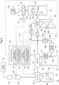
FIG. 2 is an electrical circuit diagram and a hydraulic circuit diagram. -
FIG. 3 is a flowchart of discharge control. -
FIG. 4 is a flowchart of cooling control. - Hereinafter, an embodiment serving as an example of the invention will be described based on the drawings.
- Note that, in the following description, the direction of the arrow F shown in
FIG. 1 is "the body front side", the direction of the arrow B shown inFIG. 1 is "the body back side", the direction of the arrow U shown inFIG. 1 is "the body up side", the direction of the arrow D shown inFIG. 1 is "the body down side", the direction of the front side of the sheet ofFIG. 1 is "body left side", and the direction of the back side of the sheet ofFIG. 1 is "body right side", in relation to the travel body of an electric tractor (example of "work vehicle"). - As shown in
FIG. 1 , the electric tractor includes atravel body 3 having a pair of left and rightfront wheels 1 and a pair of left andright back wheels 2. The pair of left and rightfront wheels 1 are steerable and drivable. The pair of left andright back wheels 2 are drivable. Thetravel body 3 includes a body frame 4 that is provided with afront frame 5 constituting a front portion of the body frame 4 and atransmission case 6 coupled to a back portion of thefront frame 5 and constituting a back portion of the body frame 4. In the front portion of thetravel body 3 is provided amotive section 8 that includes a travelelectric motor 7 serving as an electric actuator that drives thefront wheels 1 and theback wheels 2. In the back portion of thetravel vehicle 3 is provided adriving section 9 in which an operator rides. Thedriving section 9 is provided with a driver'sseat 10, asteering wheel 11 for steering thefront wheels 1, and aROPS 12. In a back portion of thetransmission case 6 of the body frame 4 are provided alink mechanism 13 for coupling any of various work apparatuses such as a rotary tiller (not shown) in such a manner as to be raisable and lowerable, and apower takeoff shaft 14 that takes work power from inside thetransmission case 6 and transmits the power to the coupled work apparatus. - As shown in
FIG. 1 , in addition to the travelelectric motor 7, themotive section 8 includes abattery 15 that supplies drive power to the travelelectric motor 7, and aninverter 16 that converts DC power from thebattery 15 into AC power and supplies the AC power to the travelelectric motor 7. Thebattery 15 is supported by abattery mount 5b provided in an upper portion of thefront frame 5. Theinverter 16 is disposed backward of thebattery 15. The travelelectric motor 7 is supported by thefront frame 5 in such a manner as to be disposed between left and rightside frame portions 5a of thefront frame 5 downward of thebattery 15 and theinverter 16. - Driving of the
back wheels 2 by the travelelectric motor 7 is made possible, by the travelelectric motor 7 being driven by power supplied from thebattery 15 via theinverter 16, the output of the travelelectric motor 7 being input via arotation shaft 17 to a hydrostatic continuouslyvariable transmission 6a provided in a front portion of thetransmission case 6, and the output of the continuouslyvariable transmission 6a being transmitted to a gear transmission (not shown) provided inside thetransmission case 6 and transmitted to theback wheels 2 from the gear transmission. Driving of thefront wheels 1 by the travelelectric motor 7 is made possible, by the power transmitted from the continuouslyvariable transmission 6a to the gear transmission being input to a frontwheel drive case 19 via arotation shaft 18 extending toward the body front side from thetransmission case 6. - As shown in
FIG. 1 , thelink mechanism 13 is provided with a pair of left and rightlower links 20 extending backward from a lower portion of thetransmission case 6 in such a manner as to be swingable up and down, atop link 21 extending backward from an upper portion of thetransmission case 6 in such a manner as to be swingable up and down, a pair of left andright lift arms 22 supported in such a manner as to be swingable up and down in an upper portion of thetransmission case 6, aleft lift rod 23 that couples theleft lift arm 22 and the leftlower link 20, and aright lift rod 23 that couples theright lift arm 22 and the rightlower link 20. - In the
link mechanism 13, the work apparatus is coupled to thetransmission case 6 in such a manner as to be raisable and lowerable due to the left and rightlower links 20 and thetop link 21 being coupled to the work apparatus. Due to the right andleft lift arms 22 being raised and lowered, the leftlower link 20 is raised and lowered by theleft lift arm 22 via theleft lift rod 23 and the rightlower link 20 is raised and lowered by theright lift arm 22 via theright lift rod 23, resulting in the work apparatus being raised and lowered with respect to the travel body. - As shown in
FIG. 1 , inside thetransmission case 6 is provided alift cylinder 24 serving as a hydraulic actuator coupled to arotary support shaft 22a of the left andright lift arms 22, and in an upper portion of thetransmission case 6 are provided ahydraulic pump 25 that supplies hydraulic oil to thelift cylinder 24 and anelectric motor 26 that drives thehydraulic pump 25, enabling thelink mechanism 13 to be raised and lowered. - Specifically, as shown in
FIG. 2 , thehydraulic pump 25 and thelift cylinder 24 are connected via anoperating oil path 27, and theoperation oil path 27 is provided with anoperating valve 28 that controls thelift cylinder 24. Theoperating oil path 27 has arelief oil path 29 connected thereto upstream of theoperating valve 28. Thehydraulic pump 25 is driven by theelectric motor 26, and hydraulic oil is taken from ahydraulic oil tank 31 and supplied to theoperating oil path 27. - The
operating valve 28 is switchable to a neutral position "n", a raising position "a", and a lowering position "b". When the operatingvalve 28 is switched to the raising position "a", thelift cylinder 24 extends due to hydraulic oil from thehydraulic pump 25 being supplied to thelift cylinder 24 via the operatingvalve 28, and the left and rightlower links 20 are raised due to the left and right liftarms 22 being raised by thelift cylinder 24. When the operatingvalve 28 is switched to the lowering position "b", thelift cylinder 24 retracts under the load of the work apparatus due to hydraulic oil located in thelift cylinder 24 being discharged into anoil discharge path 30 via the operatingvalve 28, and the left and rightlower links 20 are lowered due to the left and right liftarms 22 being lowered by thelift cylinder 24. When the operatingvalve 28 is switched to the neutral position "n", thelift cylinder 24 stops extending/retracting due to supply of hydraulic oil to thelift cylinder 24 and discharge of hydraulic oil from thelift cylinder 24 being stopped by the operatingvalve 28, and the left and rightlower links 20 are maintained in a swing position corresponding to the stopped position of the left and right liftarms 22 due to operation of thelift arms 22 being stopped by thelift cylinder 24. In this case, the hydraulic oil from thehydraulic pump 25 is discharged into thedischarge channel 30 from therelief oil path 29 by opening arelief valve 29a of therelief oil path 29. The hydraulic oil discharged into thedischarge channel 30 is returned to thehydraulic oil tank 31 from thedischarge channel 30. - As shown in
FIG. 2 , thebattery 15 has a chargingport 32 serving as a charging section connected thereto. As shown inFIG. 1 , the chargingport 32 is provided on the inner side of acover 8a covering thebattery 15 and the like in themotive section 8. The chargingport 32 connects thebattery 15 and apower source 33 and charges thebattery 15 from thepower source 33, due to a chargingconnector 34 that extends from thepower source 33 provided outside the vehicle body being connected thereto. - The
travel body 3 is provided with adischarge operation apparatus 35 capable of causing thebattery 15 to discharge during charging. As shown inFIG. 2 , thedischarge operation apparatus 35 is provided with adischarge circuit 36 extending between theinverter 16 and theelectric motor 26, and adischarge control section 37 linked to thedischarge circuit 36. - As shown in
FIG. 2 , thedischarge circuit 36 is provided to extend between theinverter 16 and theelectric motor 26, separately from a workingmotor drive circuit 38 that extends between theinverter 16 and theelectric motor 26. Thedischarge circuit 36 has adischarge switch 36a, and when thedischarge switch 36a is switched to "ON", thebattery 15 and theelectric motor 26 are connected due to thedischarge circuit 36 connecting theinverter 16 and theelectric motor 26, and thebattery 15 starts discharging. When thebattery 15 is discharging, thedischarge circuit 36 supplies power from the dischargedbattery 15 to theelectric motor 26 and drives theelectric motor 26, due to connecting thebattery 15 and theelectric motor 26. When thedischarge switch 36a is switched to "OFF", thebattery 15 and theelectric motor 26 are disconnected due to thedischarge circuit 36 disconnecting theinverter 16 and theelectric motor 26, and thebattery 15 stops discharging. - As shown in
FIG. 2 , thedischarge control section 37 is provided in acontrol apparatus 39. Thecontrol apparatus 39 is constituted utilizing a microcomputer. Thecontrol apparatus 39 is linked to a chargingdetection mechanism 40 that detects that thebattery 15 is charging, a batterytemperature detection mechanism 41 that detects the temperature of thebattery 15, and an operating valveposition detection mechanism 42 that detects that the operatingvalve 28 is in the neutral position "n". - The charging
detection mechanism 40 is provided in the chargingport 32, and enters a detection state of detecting that thebattery 15 is charging by detecting that the chargingconnector 34 is connected to the chargingport 32, and enters a non-detection state when the chargingconnector 34 is removed from the chargingport 32. The operating valveposition detection mechanism 42 is linked to alift lever 43 that switches the operatingvalve 28, and, when the operatingvalve 28 is switched to the neutral position "n", enters a detection state of detecting that the operatingvalve 28 is in the neutral position "n" based on the operating position of thelift lever 43, and enters a non-detection state when the operatingvalve 28 is switched to a position other than the neutral position "n", that is, the raising position "a" or the lowering position "b". Thecontrol apparatus 39 is provided with a batterytemperature setting section 44. The batterytemperature setting section 44 sets, as a set battery temperature "SB", the battery temperature of the boundary between a temperature range in which the temperature of thebattery 15 needs to be increased and a temperature range in which the temperature of thebattery 15 does not need to be increased. - As shown in
FIG. 3 , thedischarge control section 37 determines whether or not thebattery 15 is charging based on detection information of the chargingdetection mechanism 40, and, if it is determined that thebattery 15 is not charging, switches thedischarge switch 36a to "OFF". If it is determined that thebattery 15 is charging, thedischarge control section 37 receives input of a detected battery temperature "KB" detected by the batterytemperature detection mechanism 41 and the set battery temperature "SB" set by the batterytemperature setting section 44, and compares the detected battery temperature "KB" and the set battery temperature "SB" to determine whether the detected battery temperature "KB" is lower than the set battery temperature "SB". If it is determined that the detected battery temperature "KB" is not lower than the set battery temperature "SB", thedischarge control section 37 switches thedischarge switch 36a to "OFF". If it is determined that the detected battery temperature "KB" is lower than the set battery temperature "SB", thedischarge control section 37 determines whether the operatingvalve 28 is in the neutral position "n" based on detection information of the operating valveposition detection mechanism 42. If it is determined that the operatingvalve 28 is not in the neutral position "n", thedischarge control section 37 switches thedischarge switch 36a to "OFF". If it is determined that the operatingvalve 28 is in the neutral position "n", thedischarge control section 37 switches thedischarge switch 36a to "ON". - At the time of performing work, the
battery 15 is not being charged due to the chargingconnector 34 not being connected to the chargingport 32, and thus thedischarge operation apparatus 35 switches thedischarge switch 36a to "OFF" with thedischarge control section 37 based on information that the chargingdetection mechanism 40 is not in the detection state, and thebattery 15 and theelectric motor 26 are not connected by thedischarge circuit 36. However, at the time of performing work, the operator switches apump switch 38a provided in themotor drive circuit 38 to "ON", resulting theinverter 16 and theelectric motor 26 being connected by themotor drive circuit 38, and power from thebattery 15 being supplied to theelectric motor 26 to drive theelectric motor 26, and thehydraulic pump 25 being driven by theelectric motor 26 to supply hydraulic oil from thehydraulic pump 25 to the operatingoil path 27. At the time of performing work, the liftingcylinder 24 can thereby be controlled by the operatingvalve 28 and the work apparatus coupled by thelink mechanism 13 can be raised and lowered. - When the charging
connector 34 is connected to the chargingport 32, thebattery 15 is charged from thepower source 33. When the temperature of thebattery 15 is lower than the set battery temperature "SB" and the operatingvalve 28 is in the neutral position "n" in the case where thebattery 15 is charging, the chargingdetection mechanism 40 is in the detection state and the operating valveposition detection mechanism 42 is in the detection state, and, based on the detection information of the chargingdetection mechanism 40, the detection information of the batterytemperature detection mechanism 41, the detection information of the operating valveposition detection mechanism 42 and the set battery temperature "SB" of the batterytemperature setting section 44, thedischarge operation apparatus 35 switches thedischarge switch 36a to "ON" with thedischarge control section 37 and thebattery 15 starts discharging, and thebattery 15 thereby increases in temperature due to the discharging of thebattery 15, and outputs more efficiently than before the increase in temperature. Furthermore, power that is output by the dischargedbattery 15 is supplied to theelectric motor 26 via theinverter 16 and thedischarge circuit 36 to drive theelectric motor 26, and thehydraulic pump 25 is driven to supply hydraulic oil to the operatingoil path 27. The operatingvalve 28 is in the neutral position "n", and the hydraulic oil supplied to the operatingoil path 27 opens therelief valve 29a and is discharged from therelief oil path 29, and the hydraulic oil thereby increases in temperature and flows more easily than before the increase in temperature. - Even when the charging
detection mechanism 40 detects that thebattery 15 is charging, if the temperature of thebattery 15 is higher than or equal to the set battery temperature "SB", or the operatingvalve 28 is not in the neutral position "n", or the temperature of thebattery 15 is higher than or equal to the set battery temperature "SB" and the operatingvalve 28 is not in the neutral position "n", thedischarge operation apparatus 35 switches thedischarge switch 36a to "OFF" with thedischarge control section 37 based on the discharge information of the batterytemperature detection mechanism 41, the set battery temperature "SB" of the batterytemperature setting section 44 and information that the operating valveposition detection mechanism 42 is in the non-detection state, and thebattery 15 stops discharging. - The
battery 15 is charged when work is not being performed. When work is not being performed, the operator switches thepump switch 38a to "OFF", and theinverter 16 and theelectric motor 26 are not connected by themotor drive circuit 38. Accordingly, when thebattery 15 is charging, the discharge state of thebattery 15 due to thedischarge switch 36a being switched "ON" and the non-discharge state of thebattery 15 due to thedischarge switch 36a being switched "OFF" appear. - At the time of performing work, the
battery 15 is not charged by the chargingport 32, and theinverter 16 and theelectric motor 26 are not connected by thedischarge circuit 36 due to thedischarge switch 36a being switched to "OFF", but the operator switches thepump switch 38a to "ON", resulting in theinverter 16 and theelectric motor 26 being connected by the workingmotor drive circuit 38. At the time of performing work, thehydraulic pump 25 can be driven due to theelectric motor 26 being driven by power from thebattery 15. - A configuration may be adopted in which a work clutch that turns power transmission to the
power takeoff shaft 14 on and off is provided, the operating state of the work clutch is added to the conditions under which thebattery 15 is discharged during charging, with thebattery 15 being discharged during charging when the work clutch is disengaged. - As shown in
FIG. 2 , theinverter 16 serving as a power device connected to thebattery 15 is provided with acooling apparatus 45, and thecooling apparatus 45 is linked to acooling control apparatus 55. - As shown in
FIG. 2 , thecooling apparatus 45 is provided with acooling apparatus body 46 that is attached to theinverter 16 and cools theinverter 16 through heat exchange with cooling water, acirculation water channel 48 that circulates the cooling water between the coolingapparatus body 46 and a coolingwater tank 47, acirculation pump 49 that is provided in thecirculation water channel 48 and circulates the cooling water, and anelectric cooling motor 50 that drives thecirculation pump 49. Between thecirculation pump 49 and thecooling apparatus body 46 in thecirculation water channel 48 is provided acooling water cooler 51. - As shown in
FIG. 2 , the coolingcontrol apparatus 55 is provided with amotor drive circuit 56 extending betweenelectric cooling motor 50 and theinverter 16, and acooling control section 57 provided in thecontrol apparatus 39. - As shown in
FIG. 2 , themotor drive circuit 56 has acooling switch 56a, and, when thecooling switch 56a is switched to "ON", is switched to an operating state of connecting theinverter 16 and theelectric cooling motor 50 to supply power from thebattery 15 to theelectric cooling motor 50, and driving theelectric cooling motor 50 to operate thecooling apparatus 45. When thecooling switch 56a is switched to "OFF", themotor drive circuit 56 is switched to a stopped state in which power supply from thebattery 15 to theelectric cooling motor 50 is stopped due to theinverter 16 and theelectric cooling motor 50 being disconnected, and thecooling apparatus 45 is stopped due to theelectric cooling motor 50 being stopped. - As shown in
FIG. 2 , thecontrol apparatus 39 is linked to an invertertemperature detection mechanism 58 serving as a device temperature detection mechanism. Thecontrol apparatus 39 is provided with an invertertemperature setting section 59 serving as a device temperature setting section. The invertertemperature setting section 59 sets a set inverter temperature "SI" serving as the device setting temperature. As the setting inverter temperature "SI", the inverter temperature of the boundary between a temperature range in which theinverter 16 needs to be cooled and a temperature range in which theinverter 16 does not need to be cooled is set. - As shown in
FIG. 4 , the coolingcontrol section 57 inputs a detected inverter temperature "KI" of the invertertemperature detection mechanism 58 and the setting inverter temperature "SI" set by the invertertemperature setting section 59, and determines whether the detected inverter temperature "KI" is higher than or equal to the set inverter temperature "SI" through comparison the detected inverter temperature "KI" and the set inverter temperature "SI". If it is determined that the detected inverter temperature "KI" is not higher than or equal to the set inverter temperature "SI", the coolingcontrol section 57 switches thecooling switch 56a to "OFF". If it is determined that the detected inverter temperature "KI" is higher than or equal to the set inverter temperature "SI", the coolingcontrol section 57 switches thecooling switch 56a to "ON". - When the temperature of the
inverter 16 increases to higher than or equal to the set inverter temperature "SI", the coolingcontrol apparatus 55 switches thecooling switch 56a to "ON" with the coolingcontrol section 57 based on detection information of the invertertemperature detection mechanism 58 and the set inverter temperature "SI" set by the invertertemperature setting section 59, drives theelectric cooling motor 50 to operates thecooling apparatus 45, and cooling of theinverter 16 by thecooling apparatus 45 is performed. - When the temperature of the
inverter 16 falls below the set inverter temperature "SI", in cases such as where theinverter 16 is cooled by thecooling apparatus 45, the coolingcontrol apparatus 55 switches thecooling switch 56a to "OFF" with the coolingcontrol section 57 based on detection information of the invertertemperature detection mechanism 58 and the set inverter temperature "SI" of the invertertemperature setting section 59, and stops thecooling apparatus 45 by stopping theelectric cooling motor 50, and cooling by thecooling apparatus 45 of theinverter 16 is stopped. - As shown in
FIG. 2 , thebattery 15 is provided with abattery cooling apparatus 60. As work proceeds, the discharge time of thebattery 15 increases and the temperature of thebattery 15 rises. In this case, cooling thebattery 15 with thebattery cooling apparatus 60 is possible. - As shown in
FIG. 2 , thebattery cooling apparatus 60 is provided in thebattery 15 and has acooling section 61 that cools thebattery 15 with cooling water as a coolant, and acirculation water channel 63 that circulates the cooling water with acirculation pump 62 between the coolingsection 61 and a coolingwater tank 47. Thecirculation pump 62 is driven by anelectric motor 64. A cooling control apparatus can be employed in which anelectric motor 70 is driven to drive acirculation pump 68, when the temperature of theelectric motor 26 exceeds a set temperature. A cooling control apparatus can be employed in which theelectric motor 64 is driven to drive thecirculation pump 62 when the temperature of thebattery 15 increases to a set cooling start temperature, and theelectric motor 64 is stopped to stop thecirculation pump 62 when the temperature of thebattery 15 drops to the set cooling stop temperature. - As shown in
FIG. 2 , theelectric motor 26 serving as an electric device connected to thebattery 15 is provided with adevice cooling apparatus 66. As the work progresses, the driving time of theelectric motor 26 increases and the temperature of theelectric motor 26 rises. In this case, seizure of theelectric motor 26 can be avoided by cooling theelectric motor 26 with thedevice cooling apparatus 66. - The
device cooling apparatus 66 is provided in theelectric motor 26, and has a coolingwater jacket 67 that cools theelectric motor 26 with cooling water serving as a coolant, and acirculation water channel 69 that circulates cooling water between the coolingwater jacket 67 and the coolingwater tank 47 with thecirculation pump 68. Thecirculation pump 68 is driven by anelectric motor 70. A cooling control apparatus can be employed in which theelectric motor 70 is driven to drive thecirculation pump 68, when the temperature of theelectric motor 26 rises to higher than or equal to the set temperature. -
- (1) The above-described embodiment gives an example in which the charging
detection mechanism 40 and thedischarge control section 37 are provided, and thedischarge operation apparatus 35 automatically causes thebattery 15 to discharge during charging, but the invention is not limited thereto, and thedischarge operation apparatus 35 may not be provided with the chargingdetection mechanism 40 and thedischarge control section 37, and thebattery 15 may be discharged as a result of the operator operating the discharge operation apparatus during charging of thebattery 15. - (2) The above-described embodiment gives an example in which the operating
valve 28 being in the neutral position "n" is a condition for causing thebattery 15 to discharge, but the operating position of the operating valve need not be a condition. - (3) The above-described embodiment gives an example in which the
cooling apparatus 45 and the coolingcontrol apparatus 55 are provided, but thecooling apparatus 45 and the coolingcontrol apparatus 55 need not be provided. - (4) The above-described embodiment gives an example in which an inverter is employed as a power device, but the invention is not limited thereto, and a transformer, a DCDC converter or the like may be employed as the power device.
- (5) The above-described embodiment gives an example in which an electric motor is employed as an electric device, but the invention is not limited thereto, and an electric cylinder or the like may be employed as the electric device.
- (6) The above-described embodiment gives an example in which the
battery cooling apparatus 60 and thedevice cooling apparatus 66 are provided, but thebattery cooling apparatus 60 and thedevice cooling apparatus 66 need not be provided. - (7) The above-described embodiment gives an example in which the
electric motor 26 and thehydraulic pump 25 that are driven by power from thebattery 15 while thebattery 15 is discharging are provided, but theelectric motor 26 and thehydraulic pump 25 need not be provided, and the dischargingbattery 15 may simply discharge. - (8) The invention can be applied to a work vehicle provided with a battery that supplies drive power to an electric actuator and a charging section for charging the battery from a power source outside the vehicle body.
Claims (8)
- A work vehicle comprising:an electric actuator (7);a battery (15) configured to supply drive power to the electric actuator;a charging section (32) via which the battery is chargeable from a power source external to a vehicle body; anda discharge operation apparatus (35) configured to cause the battery to discharge during charging of the battery.
- The work vehicle according to claim 1, further comprising:a hydraulic pump (25) connected to a hydraulic actuator (24) via an operating oil path and configured to supply hydraulic oil to the hydraulic actuator;an operating valve (28) provided in the operating oil path and configured to control the hydraulic actuator;a relief oil path (29) connected to a portion of the operating oil channel upstream of the operating valve; andan electric motor (26) configured to drive the hydraulic pump,wherein the discharge operation apparatus (35) causes the battery to discharge by connecting the battery to the electric motor such that power is supplied to the electric motor from the battery.
- The work vehicle according to claim 1 or 2, further comprising:a charging detection mechanism (40) configured to detect charging of the battery,wherein the discharge operation apparatus (35) includes a discharge control section (37) configured to cause the battery to discharge during charging, based on detection information of the charging detection mechanism.
- The work vehicle according to claim 3, further comprising:a battery temperature detection mechanism (41) configured to detect a temperature of the battery,wherein the discharge control section (37) causes the battery to discharge during charging, in response to a battery temperature detected by the battery temperature detection mechanism being lower than a set battery temperature, and does not cause the battery to discharge during charging, in response to the detected battery temperature being higher than or equal to the set battery temperature.
- The work vehicle according to any one of claims 1 to 4, further comprising:a power device (16) connected to the battery (15);a cooling apparatus (45) configured to cool the power device;a device temperature detection mechanism (58) configured to detect a temperature of the power device; anda cooling control apparatus (55) configured to control operation of the cooling apparatus based on detection information of the device temperature detection mechanism,wherein the cooling control apparatus controls the cooling apparatus to operate, in response to a device temperature detected by the device temperature detection mechanism being higher than or equal to a set device temperature, and controls the cooling apparatus to stop operation, in response to the detected device temperature being lower than the set device temperature.
- The work vehicle according to claim 5,
wherein the power device (16) is an inverter. - The work vehicle according to any one of claims 1 to 4, further comprising:an electric device (26) connected to the battery; anda device cooling apparatus (66) configured to cool the electric device.
- The work vehicle according to any one of claims 1 to 4 or 7, further comprising:
a battery cooling apparatus (60) configured to cool the battery.
Applications Claiming Priority (1)
| Application Number | Priority Date | Filing Date | Title |
|---|---|---|---|
| JP2023000162A JP2024096586A (en) | 2023-01-04 | 2023-01-04 | Work vehicle |
Publications (2)
| Publication Number | Publication Date |
|---|---|
| EP4420916A2 true EP4420916A2 (en) | 2024-08-28 |
| EP4420916A3 EP4420916A3 (en) | 2024-12-25 |
Family
ID=89221962
Family Applications (1)
| Application Number | Title | Priority Date | Filing Date |
|---|---|---|---|
| EP23216006.9A Pending EP4420916A3 (en) | 2023-01-04 | 2023-12-12 | Work vehicle |
Country Status (3)
| Country | Link |
|---|---|
| US (1) | US20240217394A1 (en) |
| EP (1) | EP4420916A3 (en) |
| JP (1) | JP2024096586A (en) |
Families Citing this family (1)
| Publication number | Priority date | Publication date | Assignee | Title |
|---|---|---|---|---|
| CN119695330A (en) * | 2024-11-05 | 2025-03-25 | 深圳市铠祥智能科技有限公司 | Thermal management system and thermal management method for electric motorcycle |
Citations (1)
| Publication number | Priority date | Publication date | Assignee | Title |
|---|---|---|---|---|
| JP2013141875A (en) | 2012-01-10 | 2013-07-22 | Kubota Corp | Electric tractor |
Family Cites Families (10)
| Publication number | Priority date | Publication date | Assignee | Title |
|---|---|---|---|---|
| JP5366685B2 (en) * | 2009-07-02 | 2013-12-11 | 本田技研工業株式会社 | Electric vehicle |
| JP6894814B2 (en) * | 2017-09-21 | 2021-06-30 | 日立建機株式会社 | Hybrid work machine |
| JP7072424B2 (en) * | 2018-03-30 | 2022-05-20 | 本田技研工業株式会社 | Vehicle power system |
| JP2019187130A (en) * | 2018-04-12 | 2019-10-24 | トヨタ自動車株式会社 | Control system for autonomous vehicle |
| JP7072498B2 (en) * | 2018-12-26 | 2022-05-20 | 株式会社クボタ | Electric work vehicle |
| JP7165111B2 (en) * | 2019-09-26 | 2022-11-02 | 株式会社日立建機ティエラ | electric hydraulic construction machine |
| JP7458842B2 (en) * | 2020-03-18 | 2024-04-01 | 住友建機株式会社 | excavator |
| JP2022184551A (en) * | 2021-06-01 | 2022-12-13 | トヨタ自動車株式会社 | tractor |
| CN114374266A (en) * | 2022-01-25 | 2022-04-19 | 中国铁建高新装备股份有限公司 | A construction vehicle power supply system, construction vehicle and power supply control method |
| CN114714931B (en) * | 2022-05-07 | 2025-07-25 | 三一重机有限公司 | Power-up method and system of electric working machine and working machine |
-
2023
- 2023-01-04 JP JP2023000162A patent/JP2024096586A/en active Pending
- 2023-12-12 EP EP23216006.9A patent/EP4420916A3/en active Pending
- 2023-12-14 US US18/539,994 patent/US20240217394A1/en active Pending
Patent Citations (1)
| Publication number | Priority date | Publication date | Assignee | Title |
|---|---|---|---|---|
| JP2013141875A (en) | 2012-01-10 | 2013-07-22 | Kubota Corp | Electric tractor |
Also Published As
| Publication number | Publication date |
|---|---|
| US20240217394A1 (en) | 2024-07-04 |
| EP4420916A3 (en) | 2024-12-25 |
| JP2024096586A (en) | 2024-07-17 |
Similar Documents
| Publication | Publication Date | Title |
|---|---|---|
| US10358050B2 (en) | Fuel cell vehicle and method for controlling fuel cell vehicle | |
| US20170284062A1 (en) | Hybrid Construction Machine | |
| US20230225248A1 (en) | Electric Grass Cutting Machine | |
| CN108138469B (en) | Hybrid construction machine | |
| EP4420916A2 (en) | Work vehicle | |
| EP2119586A2 (en) | Hybrid industrial vehicle | |
| US11486420B2 (en) | Electric work vehicle | |
| US20200198497A1 (en) | Temperature adjustment circuit and control method thereof | |
| US20240383377A1 (en) | Electric work vehicle | |
| US20220134843A1 (en) | Cab heating system for an electric work vehicle | |
| CN114953900A (en) | Preheat intelligence for electro-hydraulic work vehicles | |
| US20180131019A1 (en) | Fuel cell vehicle and method for controlling fuel cell vehicle | |
| US12311769B2 (en) | Work vehicle | |
| JP7072498B2 (en) | Electric work vehicle | |
| US20240034195A1 (en) | Powertrain for a work machine, method for operating the powertrain, and work machine | |
| US20240317049A1 (en) | Electric work vehicle | |
| EP4397521A1 (en) | Electric work vehicle | |
| US11142441B2 (en) | Industrial vehicle | |
| JP7072499B2 (en) | Electric work vehicle | |
| JP7826598B2 (en) | electric shovel | |
| JP7616856B2 (en) | Vehicle battery cooling device | |
| JP7507742B2 (en) | Electric work vehicle | |
| US20240308389A1 (en) | Electric work vehicle | |
| WO2025100139A1 (en) | Electric work vehicle | |
| JP7359116B2 (en) | Feeding systems, industrial vehicles and feeding machines |
Legal Events
| Date | Code | Title | Description |
|---|---|---|---|
| PUAI | Public reference made under article 153(3) epc to a published international application that has entered the european phase |
Free format text: ORIGINAL CODE: 0009012 |
|
| STAA | Information on the status of an ep patent application or granted ep patent |
Free format text: STATUS: REQUEST FOR EXAMINATION WAS MADE |
|
| 17P | Request for examination filed |
Effective date: 20231212 |
|
| AK | Designated contracting states |
Kind code of ref document: A2 Designated state(s): AL AT BE BG CH CY CZ DE DK EE ES FI FR GB GR HR HU IE IS IT LI LT LU LV MC ME MK MT NL NO PL PT RO RS SE SI SK SM TR |
|
| PUAL | Search report despatched |
Free format text: ORIGINAL CODE: 0009013 |
|
| RIC1 | Information provided on ipc code assigned before grant |
Ipc: B60L 58/26 20190101ALI20241111BHEP Ipc: B60L 58/14 20190101ALI20241111BHEP Ipc: B60L 1/00 20060101AFI20241111BHEP |
|
| AK | Designated contracting states |
Kind code of ref document: A3 Designated state(s): AL AT BE BG CH CY CZ DE DK EE ES FI FR GB GR HR HU IE IS IT LI LT LU LV MC ME MK MT NL NO PL PT RO RS SE SI SK SM TR |
|
| RIC1 | Information provided on ipc code assigned before grant |
Ipc: B60L 58/26 20190101ALI20241119BHEP Ipc: B60L 58/14 20190101ALI20241119BHEP Ipc: B60L 1/00 20060101AFI20241119BHEP |