EP4420908A1 - Power transmission device and drive device - Google Patents
Power transmission device and drive device Download PDFInfo
- Publication number
- EP4420908A1 EP4420908A1 EP24158720.3A EP24158720A EP4420908A1 EP 4420908 A1 EP4420908 A1 EP 4420908A1 EP 24158720 A EP24158720 A EP 24158720A EP 4420908 A1 EP4420908 A1 EP 4420908A1
- Authority
- EP
- European Patent Office
- Prior art keywords
- gear
- bearing support
- rotation shaft
- support portion
- chamber
- Prior art date
- Legal status (The legal status is an assumption and is not a legal conclusion. Google has not performed a legal analysis and makes no representation as to the accuracy of the status listed.)
- Pending
Links
Images



Classifications
-
- F—MECHANICAL ENGINEERING; LIGHTING; HEATING; WEAPONS; BLASTING
- F16—ENGINEERING ELEMENTS AND UNITS; GENERAL MEASURES FOR PRODUCING AND MAINTAINING EFFECTIVE FUNCTIONING OF MACHINES OR INSTALLATIONS; THERMAL INSULATION IN GENERAL
- F16H—GEARING
- F16H1/00—Toothed gearings for conveying rotary motion
- F16H1/02—Toothed gearings for conveying rotary motion without gears having orbital motion
- F16H1/20—Toothed gearings for conveying rotary motion without gears having orbital motion involving more than two intermeshing members
- F16H1/22—Toothed gearings for conveying rotary motion without gears having orbital motion involving more than two intermeshing members with a plurality of driving or driven shafts; with arrangements for dividing torque between two or more intermediate shafts
-
- B—PERFORMING OPERATIONS; TRANSPORTING
- B60—VEHICLES IN GENERAL
- B60K—ARRANGEMENT OR MOUNTING OF PROPULSION UNITS OR OF TRANSMISSIONS IN VEHICLES; ARRANGEMENT OR MOUNTING OF PLURAL DIVERSE PRIME-MOVERS IN VEHICLES; AUXILIARY DRIVES FOR VEHICLES; INSTRUMENTATION OR DASHBOARDS FOR VEHICLES; ARRANGEMENTS IN CONNECTION WITH COOLING, AIR INTAKE, GAS EXHAUST OR FUEL SUPPLY OF PROPULSION UNITS IN VEHICLES
- B60K1/00—Arrangement or mounting of electrical propulsion units
- B60K1/02—Arrangement or mounting of electrical propulsion units comprising more than one electric motor
-
- B—PERFORMING OPERATIONS; TRANSPORTING
- B60—VEHICLES IN GENERAL
- B60K—ARRANGEMENT OR MOUNTING OF PROPULSION UNITS OR OF TRANSMISSIONS IN VEHICLES; ARRANGEMENT OR MOUNTING OF PLURAL DIVERSE PRIME-MOVERS IN VEHICLES; AUXILIARY DRIVES FOR VEHICLES; INSTRUMENTATION OR DASHBOARDS FOR VEHICLES; ARRANGEMENTS IN CONNECTION WITH COOLING, AIR INTAKE, GAS EXHAUST OR FUEL SUPPLY OF PROPULSION UNITS IN VEHICLES
- B60K17/00—Arrangement or mounting of transmissions in vehicles
- B60K17/04—Arrangement or mounting of transmissions in vehicles characterised by arrangement, location or kind of gearing
- B60K17/043—Transmission unit disposed in on near the vehicle wheel, or between the differential gear unit and the wheel
-
- B—PERFORMING OPERATIONS; TRANSPORTING
- B60—VEHICLES IN GENERAL
- B60K—ARRANGEMENT OR MOUNTING OF PROPULSION UNITS OR OF TRANSMISSIONS IN VEHICLES; ARRANGEMENT OR MOUNTING OF PLURAL DIVERSE PRIME-MOVERS IN VEHICLES; AUXILIARY DRIVES FOR VEHICLES; INSTRUMENTATION OR DASHBOARDS FOR VEHICLES; ARRANGEMENTS IN CONNECTION WITH COOLING, AIR INTAKE, GAS EXHAUST OR FUEL SUPPLY OF PROPULSION UNITS IN VEHICLES
- B60K7/00—Disposition of motor in, or adjacent to, traction wheel
- B60K7/0007—Disposition of motor in, or adjacent to, traction wheel the motor being electric
-
- F—MECHANICAL ENGINEERING; LIGHTING; HEATING; WEAPONS; BLASTING
- F16—ENGINEERING ELEMENTS AND UNITS; GENERAL MEASURES FOR PRODUCING AND MAINTAINING EFFECTIVE FUNCTIONING OF MACHINES OR INSTALLATIONS; THERMAL INSULATION IN GENERAL
- F16H—GEARING
- F16H57/00—General details of gearing
- F16H57/0018—Shaft assemblies for gearings
- F16H57/0037—Special features of coaxial shafts, e.g. relative support thereof
-
- F—MECHANICAL ENGINEERING; LIGHTING; HEATING; WEAPONS; BLASTING
- F16—ENGINEERING ELEMENTS AND UNITS; GENERAL MEASURES FOR PRODUCING AND MAINTAINING EFFECTIVE FUNCTIONING OF MACHINES OR INSTALLATIONS; THERMAL INSULATION IN GENERAL
- F16H—GEARING
- F16H57/00—General details of gearing
- F16H57/02—Gearboxes; Mounting gearing therein
- F16H57/021—Shaft support structures, e.g. partition walls, bearing eyes, casing walls or covers with bearings
-
- F—MECHANICAL ENGINEERING; LIGHTING; HEATING; WEAPONS; BLASTING
- F16—ENGINEERING ELEMENTS AND UNITS; GENERAL MEASURES FOR PRODUCING AND MAINTAINING EFFECTIVE FUNCTIONING OF MACHINES OR INSTALLATIONS; THERMAL INSULATION IN GENERAL
- F16H—GEARING
- F16H57/00—General details of gearing
- F16H57/02—Gearboxes; Mounting gearing therein
- F16H57/023—Mounting or installation of gears or shafts in the gearboxes, e.g. methods or means for assembly
-
- B—PERFORMING OPERATIONS; TRANSPORTING
- B60—VEHICLES IN GENERAL
- B60K—ARRANGEMENT OR MOUNTING OF PROPULSION UNITS OR OF TRANSMISSIONS IN VEHICLES; ARRANGEMENT OR MOUNTING OF PLURAL DIVERSE PRIME-MOVERS IN VEHICLES; AUXILIARY DRIVES FOR VEHICLES; INSTRUMENTATION OR DASHBOARDS FOR VEHICLES; ARRANGEMENTS IN CONNECTION WITH COOLING, AIR INTAKE, GAS EXHAUST OR FUEL SUPPLY OF PROPULSION UNITS IN VEHICLES
- B60K7/00—Disposition of motor in, or adjacent to, traction wheel
- B60K2007/0046—Disposition of motor in, or adjacent to, traction wheel the motor moving together with the vehicle body, i.e. moving independently from the wheel axle
-
- B—PERFORMING OPERATIONS; TRANSPORTING
- B60—VEHICLES IN GENERAL
- B60K—ARRANGEMENT OR MOUNTING OF PROPULSION UNITS OR OF TRANSMISSIONS IN VEHICLES; ARRANGEMENT OR MOUNTING OF PLURAL DIVERSE PRIME-MOVERS IN VEHICLES; AUXILIARY DRIVES FOR VEHICLES; INSTRUMENTATION OR DASHBOARDS FOR VEHICLES; ARRANGEMENTS IN CONNECTION WITH COOLING, AIR INTAKE, GAS EXHAUST OR FUEL SUPPLY OF PROPULSION UNITS IN VEHICLES
- B60K7/00—Disposition of motor in, or adjacent to, traction wheel
- B60K2007/0061—Disposition of motor in, or adjacent to, traction wheel the motor axle being parallel to the wheel axle
-
- B—PERFORMING OPERATIONS; TRANSPORTING
- B60—VEHICLES IN GENERAL
- B60Y—INDEXING SCHEME RELATING TO ASPECTS CROSS-CUTTING VEHICLE TECHNOLOGY
- B60Y2200/00—Type of vehicle
- B60Y2200/90—Vehicles comprising electric prime movers
- B60Y2200/91—Electric vehicles
-
- F—MECHANICAL ENGINEERING; LIGHTING; HEATING; WEAPONS; BLASTING
- F16—ENGINEERING ELEMENTS AND UNITS; GENERAL MEASURES FOR PRODUCING AND MAINTAINING EFFECTIVE FUNCTIONING OF MACHINES OR INSTALLATIONS; THERMAL INSULATION IN GENERAL
- F16H—GEARING
- F16H57/00—General details of gearing
- F16H57/02—Gearboxes; Mounting gearing therein
- F16H2057/02034—Gearboxes combined or connected with electric machines
-
- F—MECHANICAL ENGINEERING; LIGHTING; HEATING; WEAPONS; BLASTING
- F16—ENGINEERING ELEMENTS AND UNITS; GENERAL MEASURES FOR PRODUCING AND MAINTAINING EFFECTIVE FUNCTIONING OF MACHINES OR INSTALLATIONS; THERMAL INSULATION IN GENERAL
- F16H—GEARING
- F16H57/00—General details of gearing
- F16H57/02—Gearboxes; Mounting gearing therein
- F16H2057/02039—Gearboxes for particular applications
- F16H2057/02043—Gearboxes for particular applications for vehicle transmissions
-
- F—MECHANICAL ENGINEERING; LIGHTING; HEATING; WEAPONS; BLASTING
- F16—ENGINEERING ELEMENTS AND UNITS; GENERAL MEASURES FOR PRODUCING AND MAINTAINING EFFECTIVE FUNCTIONING OF MACHINES OR INSTALLATIONS; THERMAL INSULATION IN GENERAL
- F16H—GEARING
- F16H57/00—General details of gearing
- F16H57/02—Gearboxes; Mounting gearing therein
- F16H2057/02039—Gearboxes for particular applications
- F16H2057/02043—Gearboxes for particular applications for vehicle transmissions
- F16H2057/02052—Axle units; Transfer casings for four wheel drive
Definitions
- the technology disclosed in this specification relates to a power transmission device and a drive device.
- JP 2016-205444 A discloses a power transmission device including a housing having a first chamber and a second chamber, a first gear unit accommodated in the first chamber and having a first rotation shaft, and a second gear unit accommodated in the second chamber and having a second rotation shaft located coaxially with the first rotation shaft.
- the housing has a center housing located between the first chamber and the second chamber.
- the center housing has a flat plate portion, a first bearing support portion protruding from the flat plate portion toward the first chamber and supporting a first bearing located at a first end of the first rotation shaft, and a second bearing support portion protruding from the flat plate portion toward the second chamber and supporting a second bearing located at a first end of the second rotation shaft.
- the first bearing support portion and the second bearing support portion are continuously connected via the flat plate portion.
- the flat plate portion when a force is applied to the first bearing support portion from the first rotation shaft, the flat plate portion is elastically deformed together with the first bearing support portion, which may cause displacement of the second bearing support portion.
- the flat plate portion when a force is applied to the second bearing support portion from the second rotation shaft, the flat plate portion is elastically deformed together with the second bearing support portion, which may cause displacement of the first bearing support portion.
- the durability of the first bearing and the second bearing supported thereby is reduced. As a result, the durability of the power transmission device decreases.
- This specification provides a technology capable of improving the durability of a power transmission device.
- a first aspect of the present disclosure relates to a power transmission device including a housing, a first gear unit, and a second gear unit.
- the housing has a first chamber, a second chamber, and a center housing, and the center housing is located between the first chamber and the second chamber.
- the first gear unit is accommodated in the first chamber and has a first rotation shaft.
- the second gear unit is accommodated in the second chamber and has a second rotation shaft located coaxially with the first rotation shaft.
- the center housing has a flat plate portion, a first bearing support portion protruding from the flat plate portion toward the first chamber and supporting a first bearing located at a first end of the first rotation shaft, and a second bearing support portion protruding from the flat plate portion toward the second chamber and supporting a second bearing located at a first end of the second rotation shaft.
- the flat plate portion is provided with a gap in at least a part of an annular region located between the first bearing support portion and the second bearing support portion.
- the flat plate portion is provided with the gap, and the gap is interposed between the first bearing support portion and the second bearing support portion.
- the gap may be provided over an entirety of the annular region.
- the gap may extend from the annular region to an outer peripheral edge of the flat plate portion along a first direction perpendicular to a rotation axis direction of the first rotation shaft. That is, the gap may be open toward the first direction.
- part of the center housing that defines the gap has a cantilever shape. Therefore, forces transmitted to the first bearing support portion and the second bearing support portion can be suppressed.
- the first gear unit may further have a first gear supported by the first rotation shaft, a third gear meshing with the first gear, and a third rotation shaft supporting the third gear.
- the first direction may be a direction forming an angle with a direction connecting a rotation axis of the first rotation shaft and a rotation axis of the third rotation shaft.
- the force applied from the first bearing to the first bearing support portion acts along the direction connecting the rotation axis of the first rotation shaft and the rotation axis of the third rotation shaft. Therefore, the flat plate portion supporting the first bearing support portion is required to have high rigidity in the direction connecting the rotation axis of the first rotation shaft and the rotation axis of the third rotation shaft. On the other hand, the rigidity of the flat plate portion decreases in the portion where the gap is provided. Regarding these points, in the above-described configuration, the first direction, in which the gap extends in the flat plate portion, does not match the direction connecting the rotation axis of the first rotation shaft and the rotation axis of the third rotation shaft. This allows the gap to be easily provided in the flat plate portion while maintaining the required rigidity of the flat plate portion.
- the first gear unit may further have a first gear supported by the first rotation shaft, a third gear meshing with the first gear, a third rotation shaft supporting the third gear, and a third bearing support portion for supporting a third bearing located at a second end of the first rotation shaft.
- a tooth trace of the first gear may be inclined so as to be displaced forward in a rotational direction of the first gear as the tooth trace approaches the center housing.
- helical gears are employed for the first gear and the third gear meshing therewith.
- a reaction force perpendicular to each rotation shaft, as well as a reaction force parallel to each rotation shaft acts on the first gear and third gear that mesh with each other.
- a reaction force acts on the first gear in a direction away from the flat plate portion along the first rotation shaft.
- the force acting on the first bearing support portion supporting the first rotation shaft in the flat plate portion is less than the force acting on the third bearing support portion supporting the first rotation shaft on the opposite side.
- the amount of elastic deformation of the first bearing support portion can be reduced, and thus the durability of the power transmission device can be improved.
- the gap may extend from an inner region surrounded by the annular region to an outer region located outside the annular region.
- first gear unit and the second gear unit may have structures that are plane-symmetrical with each other.
- a second aspect of the present disclosure relates to a drive device for a vehicle including the power transmission device according to the first aspect, a first motor, and a second motor.
- the first motor is accommodated in the first chamber and is configured to drive the first gear unit.
- the second motor is accommodated in the second chamber and is configured to drive the second gear unit.
- the first motor and the second motor may be arranged plane-symmetrically with each other.
- the first gear unit may be a reduction gear configured to amplify torque of the first motor, and the first rotation shaft of the first gear unit may be connected to a left wheel of the vehicle via a drive shaft.
- the second gear unit may be a reduction gear configured to amplify torque of the second motor, and the second rotation shaft of the second gear unit may be connected to a right wheel of the vehicle via a drive shaft.
- FIG. 2 is a diagram of a flat plate portion 70 viewed from the left side.
- FIGS. 1 and 3 are schematic cross-sectional views of the vehicle 2 for making the description easier to understand.
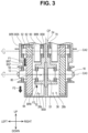
- FIG. 3 only a third intermediate gear 62 and a fourth intermediate gear 64 are illustrated in a schematic plan view in order to facilitate understanding of tooth traces of the third intermediate gear 62 and the fourth intermediate gear 64. Further, in FIG. 3 , the tooth traces of the third intermediate gear 62 and the fourth intermediate gear 64 are illustrated by bold lines.
- a traveling direction of the vehicle 2 will be referred to as a "front and rear direction”
- a right and left direction when the vehicle 2 is facing forward will be referred to as a “right and left direction”
- a direction perpendicular to the front and rear direction and the right and left direction will be referred to as an "up and lower direction”.
- the vehicle 2 includes a housing 10, a left drive shaft 12, a left rear wheel 14, a right drive shaft 16, and a right rear wheel 18.
- the vehicle 2 is, for example, a battery electric vehicle, a hybrid electric vehicle, a plug-in hybrid electric vehicle, or a fuel cell electric vehicle.
- the housing 10 includes a left housing 20, a right housing 22, and a center housing 24.
- the left housing 20 is attached to the left side of the center housing 24, and the right housing 22 is attached to the right side of the center housing 24.
- the housing 10 has a left accommodation chamber 26 and a right accommodation chamber 28.
- the left accommodation chamber 26 is defined by the left housing 20 and the center housing 24.
- the right accommodation chamber 28 is defined by the right housing 22 and the center housing 24.
- the left housing 20 includes a main body 20a and a cover 20b.
- the cover 20b is attached to a left end portion of the main body 20a.
- the right housing 22 includes a main body 22a and a cover 22b.
- the cover 22b is attached to a right end portion of the main body 22a.
- the left accommodation chamber 26 includes a left motor accommodation chamber 26a that accommodates a left motor 30, and a left gear accommodation chamber 26b that accommodates a left gear unit 32.
- the right accommodation chamber 28 includes a right motor accommodation chamber 28a that accommodates a right motor 34, and a right gear accommodation chamber 28b that accommodates a right gear unit 36.
- the right motor 34 has a configuration that is plane-symmetrical to the left motor 30 with a center plane CP interposed therebetween.
- the center plane CP is a plane including the up and lower direction and the front and rear direction.
- the right gear unit 36 has a configuration that is plane-symmetrical to the left gear unit 32 with the center plane CP extending inside the center housing 24 interposed therebetween.
- the configurations of the left motor 30 and the left gear unit 32 will be described.
- the reference numerals and letters have been omitted for components of the right motor 34 and the right gear unit 36 that are the same as those of the left motor 30 and the left gear unit 32 for ease of viewing.
- the left motor 30 has a motor shaft 40, a rotor 42, and a stator 44.
- the motor shaft 40 extends along a central axis CA1 extending in the right and left direction.
- the motor shaft 40 is rotatably supported on the left housing 20 by bearings BR1 and BR2.
- the left housing 20 is provided with bearing support portions BS1 and BS2 that support the bearings BR1 and BR2.
- the rotor 42 is fixed to the motor shaft 40.
- the stator 44 is fixed to an inner wall of the left housing 20.
- the left gear unit 32 includes a first gear shaft 50, a second gear shaft 52, and a third gear shaft 54.
- a left end portion of the first gear shaft 50 is attached to the motor shaft 40.
- the first gear shaft 50 extends along the central axis CA1.
- the first gear shaft 50 is rotatably supported by the left housing 20 via a bearing BR3, and is rotatably supported by the center housing 24 via a bearing BR4.
- the first gear shaft 50 rotatably supports a first intermediate gear 58.
- the first intermediate gear 58 may be a spur gear or a helical gear.
- the left housing 20 is provided with a bearing support portion BS3 that supports the bearing BR3, and the center housing 24 is provided with a bearing support portion BS4 that supports the bearing BR4.
- the second gear shaft 52 extends along a central axis CA2 that extends in the right and left direction.
- the second gear shaft 52 is rotatably supported by the left housing 20 via a bearing BR5, and is rotatably supported by the center housing 24 via a bearing BR6.
- the second gear shaft 52 rotatably supports a second intermediate gear 60 and the third intermediate gear 62.
- the second intermediate gear 60 meshes with the first intermediate gear 58 of the first gear shaft 50.
- the second intermediate gear 60 may be a spur gear or a helical gear.
- the outer diameter of the second intermediate gear 60 is larger than the outer diameter of the first intermediate gear 58. As illustrated in FIG.
- the third intermediate gear 62 is a so-called helical gear, and its tooth trace is inclined so as to be displaced forward in a rotational direction of the third intermediate gear 62 as it approaches the center housing 24.
- the outer diameter of the third intermediate gear 62 is smaller than the outer diameter of the second intermediate gear 60.
- the left housing 20 is provided with a bearing support portion BS5 that supports the bearing BR5
- the center housing 24 is provided with a bearing support portion BS6 that supports the bearing BR6.
- the third gear shaft 54 extends along a central axis CA3 that extends in the right and left direction.
- the third gear shaft 54 is rotatably supported by the left housing 20 via a bearing BR7 and rotatably supported by the center housing 24 via a bearing BR8.
- the third gear shaft 54 rotatably supports the fourth intermediate gear 64.
- the fourth intermediate gear 64 meshes with the third intermediate gear 62 of the second gear shaft 52.
- the fourth intermediate gear 64 is a so-called helical gear, and its tooth trace is inclined so as to be displaced forward in a rotational direction of the fourth intermediate gear 64 as it approaches the center housing 24.
- the outer diameter of the fourth intermediate gear 64 is larger than the outer diameter of each of the first to third intermediate gears 58 to 62.
- the left housing 20 is provided with a bearing support portion BS7 that supports the bearing BR7
- the center housing 24 is provided with a bearing support portion BS8 that supports the bearing BR8.
- a first end (right end) of the left drive shaft 12 is connected to the third gear shaft 54 of the left gear unit 32, and a second end (left end) of the left drive shaft 12 is connected to the left rear wheel 14.
- a first end (left end) of the right drive shaft 16 is connected to the third gear shaft 54 of the right gear unit 36, and a second end (right end) of the right drive shaft 16 is connected to the right rear wheel 18.
- the right motor 34 and the right gear unit 36 have plane-symmetrical configurations with the left motor 30 and the left gear unit 32, respectively, with the center plane CP interposed therebetween. Therefore, the first gear shaft 50 on the right side, the second gear shaft 52 on the right side, and the third gear shaft 54 on the right side are respectively provided coaxially with the first gear shaft 50 on the left side, the second gear shaft 52 on the left side, and the third gear shaft 54 on the left side.
- the center housing 24 includes the flat plate portion 70, a left attachment portion 72, and a right attachment portion 74.
- the left attachment portion 72 protrudes leftward from the left surface of the flat plate portion 70 and defines the left outer periphery of the center housing 24.
- the left attachment portion 72 is provided with a plurality of screw holes 76 for fixing the left housing 20 to the center housing 24.
- the right attachment portion 74 protrudes rightward from the right surface of the flat plate portion 70 and defines the right outer periphery of the center housing 24.
- the right attachment portion 74 is provided with a plurality of screw holes 76 for fixing the right housing 22 to the center housing 24.
- the flat plate portion 70 is provided with the bearing support portions BS4, BS6, BS8.
- the bearing support portions BS4, BS6, BS8 provided on the left side of the flat plate portion 70 protrude from the left side of the flat plate portion 70 toward the left, that is, toward the left accommodation chamber 26 (front side of the page of FIG. 2 ).
- the bearing support portions BS4, BS6, BS8 (see FIG. 1 ) provided on the right side of the flat plate portion 70 protrude from the right side of the flat plate portion 70 toward the right, that is, toward the right accommodation chamber 28 (back side of the page of FIG. 2 ).
- the bearing support portions BS4, BS6, BS8 have a cylindrical shape.
- the flat plate portion 70 may be provided with a plurality of opening portions through which oil flowing through the left accommodation chamber 26 and the right accommodation chamber 28 passes. Further, the flat plate portion 70 may be provided with a plurality of ribs to increase the strength of the center housing 24.
- the flat plate portion 70 is provided with a gap S 1 in the entirety of an annular region 80 located between the bearing support portion BS8 on the left side and the bearing support portion BS8 on the right side.
- the region where the gap S 1 is provided is indicated by a two-dot chain line.
- the gap S 1 extends from the annular region 80 to the outer peripheral edge of the flat plate portion 70 along a direction (that is, the front and rear direction) perpendicular to a direction that vertically connects the central axis CA2 of the second gear shaft 52 and the central axis CA3 of the third gear shaft 54, Specifically, the gap S1 extends in a direction perpendicular to the central axis CA3 of the third gear shaft 54. That is, the gap S1 is open toward the rear. No gap is provided in an annular region located between the bearing support portion BS4 on the left side and the bearing support portion BS4 on the right side and an annular region located between the bearing support portion BS6 on the left side and the bearing support portion BS6 on the right side.
- the third intermediate gear 62 rotates from top to bottom, and the fourth intermediate gear 64 rotates from the bottom to the top. That is, the third intermediate gear 62 rotates in a direction toward the fourth intermediate gear 64, and the fourth intermediate gear 64 rotates in a direction toward the third intermediate gear 62.
- an upward force acts on the third intermediate gear 62, and a downward force F1 is generated on the fourth intermediate gear 64.
- the third gear shaft 54 to which the fourth intermediate gear 64 is fixed is supported by the bearing support portions BS7, BS8. Therefore, when the force F1 is generated in the fourth intermediate gear 64, a force is applied from the third gear shaft 54 to the bearing support portions BS7, BS8.
- the tooth trace of the fourth intermediate gear 64 is inclined so that as it approaches the center housing 24, it is displaced forward in the rotational direction of the fourth intermediate gear 64.
- a thrust force acts on the fourth intermediate gear 64 in a direction away from the center housing 24. Therefore, a force F2 applied to the bearing support portion BS8 located on a side of the center housing 24 with respect to the fourth intermediate gear 64 is smaller than a force F3 applied to the bearing support portion BS7 located on an opposite side of the center housing 24 with respect to the fourth intermediate gear 64.
- the bearing support portion BS8 on the left side and the left portion of the flat plate portion 70 are elastically deformed.
- the elastic deformation of the flat plate portion 70 together with the elastic deformation of the bearing support portion BS8 on the left side may cause displacement of the bearing support portion BS8 on the right side.
- the gap S1 is provided in the entirety of the annular region 80 of the flat plate portion 70, even when the flat plate portion 70 is elastically deformed together with the bearing support portion BS8 on the left side, the deformation is absorbed by the gap S1, thereby suppressing displacement occurring in the bearing support portion BS8 on the right side.
- the housing 10, the left gear unit 32, and the right gear unit 36 will be collectively referred to as a "power transmission device”. Further, the power transmission device, the left motor 30, and the right motor 34 are collectively referred to as a "drive device”.
- the power transmission device includes the housing 10 having the left accommodation chamber 26 (an example of a "first chamber”) and a right accommodation chamber 28 (an example of a “second chamber”), the left gear unit 32 (an example of a “first gear unit”) accommodated in the left accommodation chamber 26 and having the third gear shaft 54 (an example of a "first rotation shaft”) on the left side, and the right gear unit 36 (an example of a "second gear unit”) accommodated in the right accommodation chamber 28 and having the third gear shaft 54 (an example of a "second rotation shaft”) on the right side located coaxially with the third gear shaft 54 on the left side.
- the housing 10 has the center housing 24 located between the left accommodation chamber 26 and the right accommodation chamber 28.
- the center housing 24 has the flat plate portion 70, the bearing support portion BS8 (an example of a "first bearing support portion”) on the left side that protrudes from the flat plate portion 70 toward the left accommodation chamber 26 and supports the bearing BR8 (an example of a "first bearing") on the left side located at a first end of the third gear shaft 54 on the left side, and the bearing support portion BS8 (an example of a "second bearing support portion”) on the right side that protrudes from the flat plate portion 70 toward the right accommodation chamber 28 and supports the bearing BR8 (an example of a "second bearing”) on the right side located at a first end of the third gear shaft 54 on the right side.
- the flat plate portion 70 is provided with the gap S 1 in at least a part of the annular region 80 located between the bearing support portion BS8 on the left side and the bearing support portion BS8 on the right side.
- the gap S 1 is provided in the flat plate portion 70, and the gap S1 is interposed between the bearing support portion BS8 on the left side and the bearing support portion BS8 on the right side. According to such a configuration, even when a force is applied from the third gear shaft 54 on the left side to the bearing support portion BS8 on the left side, and the flat plate portion 70 is elastically deformed together with the bearing support portion BS8 on the left side, since the deformation is absorbed in the gap, displacement occurring in the bearing support portion BS8 on the right side is suppressed.
- the gap S1 is provided over the entirety of the annular region 80.
- the elastic deformation occurring in one of the bearing support portion BS8 on the left side and the bearing support portion BS8 on the right side can be sufficiently absorbed in the gap S1. Thereby, the durability of the power transmission device can be further improved.
- the gap S1 extends from the annular region 80 to the outer peripheral edge of the flat plate portion 70 along the front and rear direction (an example of a "first direction") perpendicular to a rotation axis direction of the third gear shaft 54 on the left side. That is, the gap S1 is open in the front and rear direction.
- the flat plate portion 70 having the gap S1 it is easy to form the flat plate portion 70 having the gap S1. Further, since a part of the flat plate portion 70 defining the gap S1 has a cantilever shape, transmission of force can be suppressed. Therefore, the force transmitted to the bearing support portion BS8 on the left side and the bearing support portion BS8 on the right side can be suppressed.
- the left gear unit 32 further has the fourth intermediate gear 64 (an example of a "first gear") supported by the third gear shaft 54, the third intermediate gear 62 (an example of a “third gear”) meshing with the fourth intermediate gear 64, and the second gear shaft 52 (an example of a "third rotation shaft”) supporting the third intermediate gear 62.
- a direction in which the gap S 1 extends is a direction that forms an angle with the direction connecting the rotation axis of the third gear shaft 54 and the rotation axis of the second gear shaft 52.
- the force applied from the bearing BR8 on the left side to the bearing support portion BS8 on the left side acts along the direction connecting the rotation axis of the third gear shaft 54 and the rotation axis of the second gear shaft 52. Therefore, the flat plate portion 70 that supports the bearing support portion BS8 on the left side is required to have high rigidity in the direction connecting the rotation axis of the third gear shaft 54 and the rotation axis of the second gear shaft 52. On the other hand, the rigidity of the flat plate portion 70 is reduced at the portion where the gap S1 is provided.
- a direction in which the gap S 1 extends in the flat plate portion 70 does not match a direction in which the rotation axis of the third gear shaft 54 and the rotation axis of the second gear shaft 52 are connected.
- the gap S1 can be easily provided to the flat plate portion 70 while maintaining the required rigidity of the flat plate portion 70.
- the left gear unit 32 further has the fourth intermediate gear 64 supported by the third gear shaft 54, the third intermediate gear 62 meshing with the fourth intermediate gear 64, the second gear shaft 52 supporting the third intermediate gear 62, and the bearing support portion BS7 (an example of a "third bearing support portion") supporting the bearing BR7 (an example of a "third bearing”) located at the second end of the third gear shaft 54.
- the tooth trace of the fourth intermediate gear 64 is inclined so as to be displaced forward in the rotational direction of the fourth intermediate gear 64 as it approaches the center housing 24.
- helical gears are used for the fourth intermediate gear 64 and the third intermediate gear 62 meshing therewith.
- a reaction force acts on the fourth intermediate gear 64 along the third gear shaft 54 in a direction away from the flat plate portion 70.
- the force acting on the bearing support portion BS8 on the left side that supports the third gear shaft 54 in the flat plate portion 70 is smaller than the force acting on the bearing support portion BS7 on the left side that supports the third gear shaft 54 on the opposite side.
- the amount of elastic deformation of the bearing support portion BS7 on the left side can be reduced, and thus the durability of the power transmission device can be improved.
- left gear unit 32 and the right gear unit 36 have structures that are plane-symmetrical to each other.
- the drive device for the vehicle includes the power transmission device, the left motor 30 (an example of a "first motor”) accommodated in the left accommodation chamber 26 and driving the left gear unit 32, and the right motor 34 (an example of a "second motor") accommodated in the right accommodation chamber 28 and driving the right gear unit 36.
- the left motor 30 and the right motor 34 are arranged plane-symmetrically to each other.
- the third gear shaft 54 on the left side of the left gear unit 32 is connected to the left rear wheel 14 of the vehicle 2 via the left drive shaft 12, and the third gear shaft 54 on the right side of the right gear unit 36 is connected to a right rear wheel 18 of the vehicle 2 via the right drive shaft 16.
- the vehicle 2 of a second example will be described with reference to FIGS. 4 and 5 .
- the configuration of the flat plate portion 70 of the center housing 24 is different from the configuration of the flat plate portion 70 of the center housing 24 of the first example.
- the same reference numerals and letters are attached to components which are the same between the examples, and the descriptions thereof will be omitted.
- the flat plate portion 70 is provided with a gap S2 in a part of the annular region 80 located between the bearing support portion BS8 on the left side and the bearing support portion BS8 on the right side. That is, part of the annular region 80 is solid.
- the region where the gap S2 is provided is indicated by a dash double-dotted line.
- the gap S2 extends from an inner region surrounded by the annular region 80 to an outer region located outside the annular region 80. In this example, it extends downward from a position slightly above the central axis CA3. The gap S2 does not extend to an outer peripheral edge of the flat plate portion 70.
- the gap S2 extends from an inner region surrounded by the annular region 80 to an outer region located outside of the annular region 80.
- the elastic deformation occurring in one of the bearing support portion BS8 on the left side and the bearing support portion BS8 on the right side can be more effectively absorbed in the gap S2.
- the gap S 1 may not extend in a direction perpendicular to the direction connecting the rotation axis of the third gear shaft 54 and the rotation axis of the second gear shaft 52, and extend in a direction forming an angle other than a right angle with respect to the direction connecting the rotation axis of the third gear shaft 54 and the rotation axis of the second gear shaft 52.
- the gap S1 may extend in the direction (up and lower direction) connecting the rotation axis of the third gear shaft 54 and the rotation axis of the second gear shaft 52.
- the third intermediate gear 62 and the fourth intermediate gear 64 may be spur gears. Also, in another modification example, the tooth traces of the third intermediate gear 62 and the fourth intermediate gear 64 may be inclined so as to be displaced rearward in the rotational direction of the third intermediate gear 62 and rearward in the rotational direction of the fourth intermediate gear 64 as they move away from the center housing 24.
- the gap S 1 of the first example and the gap S2 of the second example may be provided only in the inner region surrounded by the annular region 80.
- the left gear unit 32 and the right gear unit 36 do not have to have structures that are plane-symmetrical with each other.
- the left gear unit 32 and the right gear unit 36 may each be connected to an engine.
- the left motor 30 and the right motor 34 do not have to have structures that are plane-symmetrical with each other.
- a gap may be provided in at least one annular region of the annular region located between the bearing support portion BS4 on the left side and the bearing support portion BS4 on the right side, and the annular region located between the bearing support portion BS6 on the left side and the bearing support portion BS6 on the right side.
- the left gear unit 32 and the right gear unit 36 are so-called three-shaft type gear units including the first gear shaft 50, the second gear shaft 52, and the third gear shaft 54.
- the left gear unit 32 and the right gear unit 36 may be two-shaft type or four-shaft type gear units.
- the first gear shaft is connected to the motors 30, 34 and the second gear shaft is connected to the rear wheels 14, 18.
- the second gear shaft connected to the left rear wheel 14 and the second gear shaft connected to the right rear wheel 18 are respectively examples of the "first rotation shaft” and the "second rotation shaft”.
- the first gear shaft is connected to the motors 30, 34.
- a fourth gear shaft is connected to the rear wheels 14, 18 and is also connected to the first gear shaft via the second gear shaft and third gear shaft.
- the fourth gear shaft connected to the left rear wheel 14 and the fourth gear shaft connected to the right rear wheel 18 are respectively examples of the "first rotation shaft” and the "second rotation shaft”.
Landscapes
- Engineering & Computer Science (AREA)
- Mechanical Engineering (AREA)
- General Engineering & Computer Science (AREA)
- Chemical & Material Sciences (AREA)
- Combustion & Propulsion (AREA)
- Transportation (AREA)
- General Details Of Gearings (AREA)
- Gear Transmission (AREA)
- Electric Propulsion And Braking For Vehicles (AREA)
- Connection Of Motors, Electrical Generators, Mechanical Devices, And The Like (AREA)
Abstract
Description
- The technology disclosed in this specification relates to a power transmission device and a drive device.
-
Japanese Unexamined Patent Application Publication No. 2016-205444 JP 2016-205444 A - In the power transmission device of
JP 2016-205444 A - This specification provides a technology capable of improving the durability of a power transmission device.
- A first aspect of the present disclosure relates to a power transmission device including a housing, a first gear unit, and a second gear unit. The housing has a first chamber, a second chamber, and a center housing, and the center housing is located between the first chamber and the second chamber. The first gear unit is accommodated in the first chamber and has a first rotation shaft. The second gear unit is accommodated in the second chamber and has a second rotation shaft located coaxially with the first rotation shaft. The center housing has a flat plate portion, a first bearing support portion protruding from the flat plate portion toward the first chamber and supporting a first bearing located at a first end of the first rotation shaft, and a second bearing support portion protruding from the flat plate portion toward the second chamber and supporting a second bearing located at a first end of the second rotation shaft. The flat plate portion is provided with a gap in at least a part of an annular region located between the first bearing support portion and the second bearing support portion.
- In the power transmission device of the first aspect, the flat plate portion is provided with the gap, and the gap is interposed between the first bearing support portion and the second bearing support portion. With such a configuration, even when a force is applied from the first rotation shaft to the first bearing support portion and the flat plate portion is elastically deformed together with the first bearing support portion, as the deformation is absorbed at the gap, displacement occurring in the second bearing support portion is suppressed. Similarly, when a force is applied to the second bearing support portion from the second rotation shaft, displacement occurring in the first bearing support portion is suppressed. As a result, for example, forces acting unintentionally on the first bearing and the second bearing are suppressed, and thus the durability of the power transmission device is improved.
- In the first aspect, the gap may be provided over an entirety of the annular region.
- With the above-described configuration, elastic deformation occurring in one of the first bearing support portion and the second bearing support portion can be sufficiently absorbed in the gap. Thereby, the durability of the power transmission device can be further improved.
- In the first aspect, the gap may extend from the annular region to an outer peripheral edge of the flat plate portion along a first direction perpendicular to a rotation axis direction of the first rotation shaft. That is, the gap may be open toward the first direction.
- With the above-described configuration, it is easy to form the flat plate portion having the gap. Also, part of the center housing that defines the gap has a cantilever shape. Therefore, forces transmitted to the first bearing support portion and the second bearing support portion can be suppressed.
- In the first aspect, the first gear unit may further have a first gear supported by the first rotation shaft, a third gear meshing with the first gear, and a third rotation shaft supporting the third gear. The first direction may be a direction forming an angle with a direction connecting a rotation axis of the first rotation shaft and a rotation axis of the third rotation shaft.
- The force applied from the first bearing to the first bearing support portion acts along the direction connecting the rotation axis of the first rotation shaft and the rotation axis of the third rotation shaft. Therefore, the flat plate portion supporting the first bearing support portion is required to have high rigidity in the direction connecting the rotation axis of the first rotation shaft and the rotation axis of the third rotation shaft. On the other hand, the rigidity of the flat plate portion decreases in the portion where the gap is provided. Regarding these points, in the above-described configuration, the first direction, in which the gap extends in the flat plate portion, does not match the direction connecting the rotation axis of the first rotation shaft and the rotation axis of the third rotation shaft. This allows the gap to be easily provided in the flat plate portion while maintaining the required rigidity of the flat plate portion.
- In the first aspect, the first gear unit may further have a first gear supported by the first rotation shaft, a third gear meshing with the first gear, a third rotation shaft supporting the third gear, and a third bearing support portion for supporting a third bearing located at a second end of the first rotation shaft. A tooth trace of the first gear may be inclined so as to be displaced forward in a rotational direction of the first gear as the tooth trace approaches the center housing.
- In the configuration, helical gears are employed for the first gear and the third gear meshing therewith. In this case, a reaction force perpendicular to each rotation shaft, as well as a reaction force parallel to each rotation shaft, acts on the first gear and third gear that mesh with each other. In this case, when the tooth trace of the first gear is displaced forward in the rotational direction of the first gear as it approaches the center housing, a reaction force acts on the first gear in a direction away from the flat plate portion along the first rotation shaft. As a result, the force acting on the first bearing support portion supporting the first rotation shaft in the flat plate portion is less than the force acting on the third bearing support portion supporting the first rotation shaft on the opposite side. As a result, the amount of elastic deformation of the first bearing support portion can be reduced, and thus the durability of the power transmission device can be improved.
- In the first aspect, the gap may extend from an inner region surrounded by the annular region to an outer region located outside the annular region.
- With the above-described configuration, elastic deformation occurring in one of the first bearing support portion and the second bearing support portion can be more effectively absorbed in the gap.
- In the first aspect, the first gear unit and the second gear unit may have structures that are plane-symmetrical with each other.
- A second aspect of the present disclosure relates to a drive device for a vehicle including the power transmission device according to the first aspect, a first motor, and a second motor. The first motor is accommodated in the first chamber and is configured to drive the first gear unit. The second motor is accommodated in the second chamber and is configured to drive the second gear unit. The first motor and the second motor may be arranged plane-symmetrically with each other. The first gear unit may be a reduction gear configured to amplify torque of the first motor, and the first rotation shaft of the first gear unit may be connected to a left wheel of the vehicle via a drive shaft. The second gear unit may be a reduction gear configured to amplify torque of the second motor, and the second rotation shaft of the second gear unit may be connected to a right wheel of the vehicle via a drive shaft.
- In the configuration, since the amplified torque of the first motor acts on the first rotation shaft, a relatively large force acts on the first bearing support portion from the first rotation shaft. Similarly, a relatively large force acts on the second bearing support portion. Therefore, a relatively large elastic deformation may occur in the first bearing support portion and the second bearing support portion. By adopting the present technology in such a configuration and providing the gap in the flat plate portion interposed between the first bearing support portion and the second bearing support portion, the durability of the drive device can be effectively improved.
- Features, advantages, and technical and industrial significance of exemplary embodiments of the invention will be described below with reference to the accompanying drawings, in which like signs denote like elements, and wherein:
-
FIG. 1 is a schematic diagram of a vehicle; -
FIG. 2 is a left view of a center housing viewed from the left side; -
FIG. 3 is an enlarged schematic diagram of a part of a left gear unit and a right gear unit; -
FIG. 4 is an enlarged schematic diagram of a part of a left gear unit and a right gear unit of a second example; and -
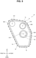
FIG. 5 is a left view of a center housing of the second example when viewed from the left side. - A
vehicle 2 of this example will be described with reference toFIGS. 1 to 3 .FIG. 2 is a diagram of aflat plate portion 70 viewed from the left side.FIGS. 1 and3 are schematic cross-sectional views of thevehicle 2 for making the description easier to understand. InFIG. 3 , only a thirdintermediate gear 62 and a fourthintermediate gear 64 are illustrated in a schematic plan view in order to facilitate understanding of tooth traces of the thirdintermediate gear 62 and the fourthintermediate gear 64. Further, inFIG. 3 , the tooth traces of the thirdintermediate gear 62 and the fourthintermediate gear 64 are illustrated by bold lines. Hereinafter, a traveling direction of thevehicle 2 will be referred to as a "front and rear direction", a right and left direction when thevehicle 2 is facing forward will be referred to as a "right and left direction", and a direction perpendicular to the front and rear direction and the right and left direction will be referred to as an "up and lower direction". - As illustrated in
FIG. 1 , thevehicle 2 includes ahousing 10, aleft drive shaft 12, a leftrear wheel 14, aright drive shaft 16, and a rightrear wheel 18. Thevehicle 2 is, for example, a battery electric vehicle, a hybrid electric vehicle, a plug-in hybrid electric vehicle, or a fuel cell electric vehicle. - The
housing 10 includes aleft housing 20, aright housing 22, and acenter housing 24. Theleft housing 20 is attached to the left side of thecenter housing 24, and theright housing 22 is attached to the right side of thecenter housing 24. Thehousing 10 has aleft accommodation chamber 26 and aright accommodation chamber 28. Theleft accommodation chamber 26 is defined by theleft housing 20 and thecenter housing 24. Theright accommodation chamber 28 is defined by theright housing 22 and thecenter housing 24. - The
left housing 20 includes amain body 20a and acover 20b. Thecover 20b is attached to a left end portion of themain body 20a. Theright housing 22 includes amain body 22a and acover 22b. Thecover 22b is attached to a right end portion of themain body 22a. - The
left accommodation chamber 26 includes a leftmotor accommodation chamber 26a that accommodates aleft motor 30, and a leftgear accommodation chamber 26b that accommodates aleft gear unit 32. Theright accommodation chamber 28 includes a rightmotor accommodation chamber 28a that accommodates aright motor 34, and a rightgear accommodation chamber 28b that accommodates aright gear unit 36. Theright motor 34 has a configuration that is plane-symmetrical to theleft motor 30 with a center plane CP interposed therebetween. The center plane CP is a plane including the up and lower direction and the front and rear direction. Theright gear unit 36 has a configuration that is plane-symmetrical to theleft gear unit 32 with the center plane CP extending inside thecenter housing 24 interposed therebetween. Below, the configurations of theleft motor 30 and theleft gear unit 32 will be described. In theright motor 34 and theright gear unit 36, the reference numerals and letters have been omitted for components of theright motor 34 and theright gear unit 36 that are the same as those of theleft motor 30 and theleft gear unit 32 for ease of viewing. - The
left motor 30 has amotor shaft 40, arotor 42, and astator 44. Themotor shaft 40 extends along a central axis CA1 extending in the right and left direction. Themotor shaft 40 is rotatably supported on theleft housing 20 by bearings BR1 and BR2. Theleft housing 20 is provided with bearing support portions BS1 and BS2 that support the bearings BR1 and BR2. Therotor 42 is fixed to themotor shaft 40. Thestator 44 is fixed to an inner wall of theleft housing 20. - The
left gear unit 32 includes afirst gear shaft 50, asecond gear shaft 52, and athird gear shaft 54. A left end portion of thefirst gear shaft 50 is attached to themotor shaft 40. Thefirst gear shaft 50 extends along the central axis CA1. Thefirst gear shaft 50 is rotatably supported by theleft housing 20 via a bearing BR3, and is rotatably supported by thecenter housing 24 via a bearing BR4. Thefirst gear shaft 50 rotatably supports a firstintermediate gear 58. The firstintermediate gear 58 may be a spur gear or a helical gear. Theleft housing 20 is provided with a bearing support portion BS3 that supports the bearing BR3, and thecenter housing 24 is provided with a bearing support portion BS4 that supports the bearing BR4. - The
second gear shaft 52 extends along a central axis CA2 that extends in the right and left direction. Thesecond gear shaft 52 is rotatably supported by theleft housing 20 via a bearing BR5, and is rotatably supported by thecenter housing 24 via a bearing BR6. Thesecond gear shaft 52 rotatably supports a secondintermediate gear 60 and the thirdintermediate gear 62. The secondintermediate gear 60 meshes with the firstintermediate gear 58 of thefirst gear shaft 50. The secondintermediate gear 60 may be a spur gear or a helical gear. The outer diameter of the secondintermediate gear 60 is larger than the outer diameter of the firstintermediate gear 58. As illustrated inFIG. 3 , the thirdintermediate gear 62 is a so-called helical gear, and its tooth trace is inclined so as to be displaced forward in a rotational direction of the thirdintermediate gear 62 as it approaches thecenter housing 24. The outer diameter of the thirdintermediate gear 62 is smaller than the outer diameter of the secondintermediate gear 60. As illustrated inFIG. 1 , theleft housing 20 is provided with a bearing support portion BS5 that supports the bearing BR5, and thecenter housing 24 is provided with a bearing support portion BS6 that supports the bearing BR6. - The
third gear shaft 54 extends along a central axis CA3 that extends in the right and left direction. Thethird gear shaft 54 is rotatably supported by theleft housing 20 via a bearing BR7 and rotatably supported by thecenter housing 24 via a bearing BR8. Thethird gear shaft 54 rotatably supports the fourthintermediate gear 64. The fourthintermediate gear 64 meshes with the thirdintermediate gear 62 of thesecond gear shaft 52. As illustrated inFIG. 3 , the fourthintermediate gear 64 is a so-called helical gear, and its tooth trace is inclined so as to be displaced forward in a rotational direction of the fourthintermediate gear 64 as it approaches thecenter housing 24. The outer diameter of the fourthintermediate gear 64 is larger than the outer diameter of each of the first to thirdintermediate gears 58 to 62. As illustrated inFIG. 1 , theleft housing 20 is provided with a bearing support portion BS7 that supports the bearing BR7, and thecenter housing 24 is provided with a bearing support portion BS8 that supports the bearing BR8. - A first end (right end) of the
left drive shaft 12 is connected to thethird gear shaft 54 of theleft gear unit 32, and a second end (left end) of theleft drive shaft 12 is connected to the leftrear wheel 14. A first end (left end) of theright drive shaft 16 is connected to thethird gear shaft 54 of theright gear unit 36, and a second end (right end) of theright drive shaft 16 is connected to the rightrear wheel 18. - As described above, the
right motor 34 and theright gear unit 36 have plane-symmetrical configurations with theleft motor 30 and theleft gear unit 32, respectively, with the center plane CP interposed therebetween. Therefore, thefirst gear shaft 50 on the right side, thesecond gear shaft 52 on the right side, and thethird gear shaft 54 on the right side are respectively provided coaxially with thefirst gear shaft 50 on the left side, thesecond gear shaft 52 on the left side, and thethird gear shaft 54 on the left side. - As illustrated in
FIG. 2 , thecenter housing 24 includes theflat plate portion 70, aleft attachment portion 72, and aright attachment portion 74. Theleft attachment portion 72 protrudes leftward from the left surface of theflat plate portion 70 and defines the left outer periphery of thecenter housing 24. Theleft attachment portion 72 is provided with a plurality of screw holes 76 for fixing theleft housing 20 to thecenter housing 24. Theright attachment portion 74 protrudes rightward from the right surface of theflat plate portion 70 and defines the right outer periphery of thecenter housing 24. Theright attachment portion 74 is provided with a plurality of screw holes 76 for fixing theright housing 22 to thecenter housing 24. - The
flat plate portion 70 is provided with the bearing support portions BS4, BS6, BS8. The bearing support portions BS4, BS6, BS8 provided on the left side of theflat plate portion 70 protrude from the left side of theflat plate portion 70 toward the left, that is, toward the left accommodation chamber 26 (front side of the page ofFIG. 2 ). Also, the bearing support portions BS4, BS6, BS8 (seeFIG. 1 ) provided on the right side of theflat plate portion 70 protrude from the right side of theflat plate portion 70 toward the right, that is, toward the right accommodation chamber 28 (back side of the page ofFIG. 2 ). The bearing support portions BS4, BS6, BS8 have a cylindrical shape. Theflat plate portion 70 may be provided with a plurality of opening portions through which oil flowing through theleft accommodation chamber 26 and theright accommodation chamber 28 passes. Further, theflat plate portion 70 may be provided with a plurality of ribs to increase the strength of thecenter housing 24. - As illustrated in
FIG. 1 , theflat plate portion 70 is provided with a gap S 1 in the entirety of anannular region 80 located between the bearing support portion BS8 on the left side and the bearing support portion BS8 on the right side. InFIG. 2 , the region where the gap S 1 is provided is indicated by a two-dot chain line. The gap S 1 extends from theannular region 80 to the outer peripheral edge of theflat plate portion 70 along a direction (that is, the front and rear direction) perpendicular to a direction that vertically connects the central axis CA2 of thesecond gear shaft 52 and the central axis CA3 of thethird gear shaft 54, Specifically, the gap S1 extends in a direction perpendicular to the central axis CA3 of thethird gear shaft 54. That is, the gap S1 is open toward the rear. No gap is provided in an annular region located between the bearing support portion BS4 on the left side and the bearing support portion BS4 on the right side and an annular region located between the bearing support portion BS6 on the left side and the bearing support portion BS6 on the right side. - With reference to
FIGS. 1 and3 , a force applied from thethird gear shaft 54 to the bearing support portion BS7 of theleft housing 20 and the bearing support portion BS8 of thecenter housing 24 when theleft motor 30 is driven will be described. - When the
left motor 30 inFIG. 1 is driven, themotor shaft 40 rotates. As themotor shaft 40 rotates, thefirst gear shaft 50 attached to themotor shaft 40 rotates. As thefirst gear shaft 50 rotates, the firstintermediate gear 58 rotatably supported by thefirst gear shaft 50, the secondintermediate gear 60 meshing with the firstintermediate gear 58, and thesecond gear shaft 52 rotatably supporting the secondintermediate gear 60 rotate. Then, as thesecond gear shaft 52 rotates, the thirdintermediate gear 62 rotatably supported by thesecond gear shaft 52, the fourthintermediate gear 64 meshing with the thirdintermediate gear 62, and thethird gear shaft 54 rotatably supporting the fourthintermediate gear 64 rotate. InFIG. 3 , the thirdintermediate gear 62 rotates from top to bottom, and the fourthintermediate gear 64 rotates from the bottom to the top. That is, the thirdintermediate gear 62 rotates in a direction toward the fourthintermediate gear 64, and the fourthintermediate gear 64 rotates in a direction toward the thirdintermediate gear 62. In this case, an upward force acts on the thirdintermediate gear 62, and a downward force F1 is generated on the fourthintermediate gear 64. Thethird gear shaft 54 to which the fourthintermediate gear 64 is fixed is supported by the bearing support portions BS7, BS8. Therefore, when the force F1 is generated in the fourthintermediate gear 64, a force is applied from thethird gear shaft 54 to the bearing support portions BS7, BS8. In this embodiment, the tooth trace of the fourthintermediate gear 64 is inclined so that as it approaches thecenter housing 24, it is displaced forward in the rotational direction of the fourthintermediate gear 64. A thrust force acts on the fourthintermediate gear 64 in a direction away from thecenter housing 24. Therefore, a force F2 applied to the bearing support portion BS8 located on a side of thecenter housing 24 with respect to the fourthintermediate gear 64 is smaller than a force F3 applied to the bearing support portion BS7 located on an opposite side of thecenter housing 24 with respect to the fourthintermediate gear 64. - When the force F2 is applied to the bearing support portion BS8 on the left side, the bearing support portion BS8 on the left side and the left portion of the
flat plate portion 70 are elastically deformed. When the bearing support portion BS8 on the left side and the bearing support portion BS8 on the right side are continuously connected via theflat plate portion 70, the elastic deformation of theflat plate portion 70 together with the elastic deformation of the bearing support portion BS8 on the left side may cause displacement of the bearing support portion BS8 on the right side. In this example, since the gap S1 is provided in the entirety of theannular region 80 of theflat plate portion 70, even when theflat plate portion 70 is elastically deformed together with the bearing support portion BS8 on the left side, the deformation is absorbed by the gap S1, thereby suppressing displacement occurring in the bearing support portion BS8 on the right side. - Hereinafter, the
housing 10, theleft gear unit 32, and theright gear unit 36 will be collectively referred to as a "power transmission device". Further, the power transmission device, theleft motor 30, and theright motor 34 are collectively referred to as a "drive device". - As described above, the power transmission device includes the
housing 10 having the left accommodation chamber 26 (an example of a "first chamber") and a right accommodation chamber 28 (an example of a "second chamber"), the left gear unit 32 (an example of a "first gear unit") accommodated in theleft accommodation chamber 26 and having the third gear shaft 54 (an example of a "first rotation shaft") on the left side, and the right gear unit 36 (an example of a "second gear unit") accommodated in theright accommodation chamber 28 and having the third gear shaft 54 (an example of a "second rotation shaft") on the right side located coaxially with thethird gear shaft 54 on the left side. Thehousing 10 has thecenter housing 24 located between theleft accommodation chamber 26 and theright accommodation chamber 28. Thecenter housing 24 has theflat plate portion 70, the bearing support portion BS8 (an example of a "first bearing support portion") on the left side that protrudes from theflat plate portion 70 toward theleft accommodation chamber 26 and supports the bearing BR8 (an example of a "first bearing") on the left side located at a first end of thethird gear shaft 54 on the left side, and the bearing support portion BS8 (an example of a "second bearing support portion") on the right side that protrudes from theflat plate portion 70 toward theright accommodation chamber 28 and supports the bearing BR8 (an example of a "second bearing") on the right side located at a first end of thethird gear shaft 54 on the right side. Theflat plate portion 70 is provided with the gap S 1 in at least a part of theannular region 80 located between the bearing support portion BS8 on the left side and the bearing support portion BS8 on the right side. - According to the above-described configuration, the gap S 1 is provided in the
flat plate portion 70, and the gap S1 is interposed between the bearing support portion BS8 on the left side and the bearing support portion BS8 on the right side. According to such a configuration, even when a force is applied from thethird gear shaft 54 on the left side to the bearing support portion BS8 on the left side, and theflat plate portion 70 is elastically deformed together with the bearing support portion BS8 on the left side, since the deformation is absorbed in the gap, displacement occurring in the bearing support portion BS8 on the right side is suppressed. Similarly, when a force is applied from thethird gear shaft 54 on the right side to the bearing support portion BS8 on the right side, displacement occurring in the bearing support portion BS8 on the left side is suppressed. As a result, for example, forces acting unintentionally on the bearing support portion BS8 on the left side and the bearing support portion BS8 on the right side are suppressed, improving the durability of the power transmission device. - Also, the gap S1 is provided over the entirety of the
annular region 80. - According to the above-described configuration, the elastic deformation occurring in one of the bearing support portion BS8 on the left side and the bearing support portion BS8 on the right side can be sufficiently absorbed in the gap S1. Thereby, the durability of the power transmission device can be further improved.
- Further, the gap S1 extends from the
annular region 80 to the outer peripheral edge of theflat plate portion 70 along the front and rear direction (an example of a "first direction") perpendicular to a rotation axis direction of thethird gear shaft 54 on the left side. That is, the gap S1 is open in the front and rear direction. - According to the above-described configuration, it is easy to form the
flat plate portion 70 having the gap S1. Further, since a part of theflat plate portion 70 defining the gap S1 has a cantilever shape, transmission of force can be suppressed. Therefore, the force transmitted to the bearing support portion BS8 on the left side and the bearing support portion BS8 on the right side can be suppressed. - In addition, the
left gear unit 32 further has the fourth intermediate gear 64 (an example of a "first gear") supported by thethird gear shaft 54, the third intermediate gear 62 (an example of a "third gear") meshing with the fourthintermediate gear 64, and the second gear shaft 52 (an example of a "third rotation shaft") supporting the thirdintermediate gear 62. A direction in which the gap S 1 extends is a direction that forms an angle with the direction connecting the rotation axis of thethird gear shaft 54 and the rotation axis of thesecond gear shaft 52. - The force applied from the bearing BR8 on the left side to the bearing support portion BS8 on the left side acts along the direction connecting the rotation axis of the
third gear shaft 54 and the rotation axis of thesecond gear shaft 52. Therefore, theflat plate portion 70 that supports the bearing support portion BS8 on the left side is required to have high rigidity in the direction connecting the rotation axis of thethird gear shaft 54 and the rotation axis of thesecond gear shaft 52. On the other hand, the rigidity of theflat plate portion 70 is reduced at the portion where the gap S1 is provided. Regarding these points, in the above-described configuration, a direction in which the gap S 1 extends in theflat plate portion 70 does not match a direction in which the rotation axis of thethird gear shaft 54 and the rotation axis of thesecond gear shaft 52 are connected. Thereby, the gap S1 can be easily provided to theflat plate portion 70 while maintaining the required rigidity of theflat plate portion 70. - In addition, the
left gear unit 32 further has the fourthintermediate gear 64 supported by thethird gear shaft 54, the thirdintermediate gear 62 meshing with the fourthintermediate gear 64, thesecond gear shaft 52 supporting the thirdintermediate gear 62, and the bearing support portion BS7 (an example of a "third bearing support portion") supporting the bearing BR7 (an example of a "third bearing") located at the second end of thethird gear shaft 54. The tooth trace of the fourthintermediate gear 64 is inclined so as to be displaced forward in the rotational direction of the fourthintermediate gear 64 as it approaches thecenter housing 24. - In the above-described configuration, helical gears are used for the fourth
intermediate gear 64 and the thirdintermediate gear 62 meshing therewith. In this case, a reaction force perpendicular to each rotation shaft, as well as a reaction force parallel to each rotation shaft, acts on the fourthintermediate gear 64 and the thirdintermediate gear 62 that mesh with each other. In this case, when the tooth trace of the fourthintermediate gear 64 is displaced forward in the rotational direction of the fourthintermediate gear 64 as it approaches thecenter housing 24, a reaction force acts on the fourthintermediate gear 64 along thethird gear shaft 54 in a direction away from theflat plate portion 70. As a result, the force acting on the bearing support portion BS8 on the left side that supports thethird gear shaft 54 in theflat plate portion 70 is smaller than the force acting on the bearing support portion BS7 on the left side that supports thethird gear shaft 54 on the opposite side. Thereby, the amount of elastic deformation of the bearing support portion BS7 on the left side can be reduced, and thus the durability of the power transmission device can be improved. - Further, the
left gear unit 32 and theright gear unit 36 have structures that are plane-symmetrical to each other. - In addition, the drive device for the vehicle includes the power transmission device, the left motor 30 (an example of a "first motor") accommodated in the
left accommodation chamber 26 and driving theleft gear unit 32, and the right motor 34 (an example of a "second motor") accommodated in theright accommodation chamber 28 and driving theright gear unit 36. Theleft motor 30 and theright motor 34 are arranged plane-symmetrically to each other. Thethird gear shaft 54 on the left side of theleft gear unit 32 is connected to the leftrear wheel 14 of thevehicle 2 via theleft drive shaft 12, and thethird gear shaft 54 on the right side of theright gear unit 36 is connected to a rightrear wheel 18 of thevehicle 2 via theright drive shaft 16. - In the above-described configuration, since the amplified torque of the
left motor 30 acts on thethird gear shaft 54, a relatively large force acts on the bearing support portion BS8 on the left side from thethird gear shaft 54. Similarly, a relatively large force acts on the bearing support portion BS8 on the right side. Therefore, a relatively large elastic deformation may occur in the bearing support portion BS8 on the left side and the bearing support portion BS8 on the right side. By adopting the present technology in such a configuration and providing the gap S1 in theflat plate portion 70 interposed between the bearing support portion BS8 on the left side and the bearing support portion BS8 on the right side, the durability of the drive device can be effectively improved. - The
vehicle 2 of a second example will be described with reference toFIGS. 4 and5 . In thevehicle 2 of the second example, the configuration of theflat plate portion 70 of thecenter housing 24 is different from the configuration of theflat plate portion 70 of thecenter housing 24 of the first example. In addition, the same reference numerals and letters are attached to components which are the same between the examples, and the descriptions thereof will be omitted. - As illustrated in
FIG. 4 , theflat plate portion 70 is provided with a gap S2 in a part of theannular region 80 located between the bearing support portion BS8 on the left side and the bearing support portion BS8 on the right side. That is, part of theannular region 80 is solid. InFIG. 5 , the region where the gap S2 is provided is indicated by a dash double-dotted line. The gap S2 extends from an inner region surrounded by theannular region 80 to an outer region located outside theannular region 80. In this example, it extends downward from a position slightly above the central axis CA3. The gap S2 does not extend to an outer peripheral edge of theflat plate portion 70. - As described above, the gap S2 extends from an inner region surrounded by the
annular region 80 to an outer region located outside of theannular region 80. - With the above-described configuration, the elastic deformation occurring in one of the bearing support portion BS8 on the left side and the bearing support portion BS8 on the right side can be more effectively absorbed in the gap S2.
- Although specific examples of the technology disclosed in this specification are described above in detail, these are merely examples and do not limit the scope of the claims. The technologies described in the claims include various modifications and changes to the specific examples illustrated above.
- In the first example, the gap S 1 may not extend in a direction perpendicular to the direction connecting the rotation axis of the
third gear shaft 54 and the rotation axis of thesecond gear shaft 52, and extend in a direction forming an angle other than a right angle with respect to the direction connecting the rotation axis of thethird gear shaft 54 and the rotation axis of thesecond gear shaft 52. - In the first example, the gap S1 may extend in the direction (up and lower direction) connecting the rotation axis of the
third gear shaft 54 and the rotation axis of thesecond gear shaft 52. - In the first and second examples, the third
intermediate gear 62 and the fourthintermediate gear 64 may be spur gears. Also, in another modification example, the tooth traces of the thirdintermediate gear 62 and the fourthintermediate gear 64 may be inclined so as to be displaced rearward in the rotational direction of the thirdintermediate gear 62 and rearward in the rotational direction of the fourthintermediate gear 64 as they move away from thecenter housing 24. - The gap S 1 of the first example and the gap S2 of the second example may be provided only in the inner region surrounded by the
annular region 80. - The
left gear unit 32 and theright gear unit 36 do not have to have structures that are plane-symmetrical with each other. - The
left gear unit 32 and theright gear unit 36 may each be connected to an engine. - The
left motor 30 and theright motor 34 do not have to have structures that are plane-symmetrical with each other. - A gap may be provided in at least one annular region of the annular region located between the bearing support portion BS4 on the left side and the bearing support portion BS4 on the right side, and the annular region located between the bearing support portion BS6 on the left side and the bearing support portion BS6 on the right side.
- In the first and second examples, the
left gear unit 32 and theright gear unit 36 are so-called three-shaft type gear units including thefirst gear shaft 50, thesecond gear shaft 52, and thethird gear shaft 54. Theleft gear unit 32 and theright gear unit 36 may be two-shaft type or four-shaft type gear units. When theleft gear unit 32 and theright gear unit 36 are two-shaft type gears, the first gear shaft is connected to themotors rear wheels rear wheel 14 and the second gear shaft connected to the rightrear wheel 18 are respectively examples of the "first rotation shaft" and the "second rotation shaft". When theleft gear unit 32 and theright gear unit 36 are four-shaft type gear units, the first gear shaft is connected to themotors rear wheels rear wheel 14 and the fourth gear shaft connected to the rightrear wheel 18 are respectively examples of the "first rotation shaft" and the "second rotation shaft". - Further, the technical elements described in this specification or the drawings exhibit technical usefulness singly or in various combinations, and are not limited to the combinations described in the claims as filed. Furthermore, the technologies illustrated in this specification or the drawings can achieve multiple objectives simultaneously, and achieving one of the objectives has technical utility in itself.
Claims (8)
- A power transmission device comprising:a housing (10) having a first chamber, a second chamber, and a center housing, the center housing being located between the first chamber and the second chamber;a first gear unit (32) accommodated in the first chamber and having a first rotation shaft; anda second gear unit (36) accommodated in the second chamber and having a second rotation shaft located coaxially with the first rotation shaft, wherein:the center housing has a flat plate portion, a first bearing support portion protruding from the flat plate portion toward the first chamber and supporting a first bearing located at a first end of the first rotation shaft, and a second bearing support portion protruding from the flat plate portion toward the second chamber and supporting a second bearing located at a first end of the second rotation shaft; andthe flat plate portion is provided with a gap in at least a part of an annular region located between the first bearing support portion and the second bearing support portion.
- The power transmission device according to claim 1, wherein the gap is provided over an entirety of the annular region.
- The power transmission device according to claim 2, wherein the gap extends from the annular region to an outer peripheral edge of the flat plate portion along a first direction perpendicular to a rotation axis direction of the first rotation shaft.
- The power transmission device according to claim 3, whereinthe first gear unit (32) further has a first gear supported by the first rotation shaft, a third gear meshing with the first gear, and a third rotation shaft supporting the third gear, andthe first direction is a direction forming an angle with a direction connecting a rotation axis of the first rotation shaft and a rotation axis of the third rotation shaft.
- The power transmission device according to claim 1, whereinthe first gear unit (32) further has a first gear supported by the first rotation shaft, a third gear meshing with the first gear, a third rotation shaft supporting the third gear, and a third bearing support portion for supporting a third bearing located at a second end of the first rotation shaft,a tooth trace of the first gear is inclined so as to be displaced forward in a rotational direction of the first gear as the tooth trace approaches the center housing.
- The power transmission device according to claim 1, wherein the gap extends from an inner region surrounded by the annular region to an outer region located outside the annular region.
- The power transmission device according to claim 1, wherein the first gear unit (32) and the second gear unit (36) have structures that are plane-symmetrical with each other.
- A drive device for a vehicle comprising:the power transmission device according to claim 1;a first motor (30) accommodated in the first chamber and configured to drive the first gear unit (32); anda second motor (34) accommodated in the second chamber and configured to drive the second gear unit (36), whereinthe first motor (30) and the second motor (34) are arranged plane-symmetrically with each other,the first gear unit (32) is a reduction gear configured to amplify torque of the first motor (30), and the first rotation shaft of the first gear unit (32) is connected to a left wheel of the vehicle via a drive shaft, andthe second gear unit (36) is a reduction gear configured to amplify torque of the second motor (34), and the second rotation shaft of the second gear unit (36) is connected to a right wheel of the vehicle via a drive shaft.
Applications Claiming Priority (1)
| Application Number | Priority Date | Filing Date | Title |
|---|---|---|---|
| JP2023026050A JP2024119268A (en) | 2023-02-22 | 2023-02-22 | Power transmission device and drive device |
Publications (1)
| Publication Number | Publication Date |
|---|---|
| EP4420908A1 true EP4420908A1 (en) | 2024-08-28 |
Family
ID=90014307
Family Applications (1)
| Application Number | Title | Priority Date | Filing Date |
|---|---|---|---|
| EP24158720.3A Pending EP4420908A1 (en) | 2023-02-22 | 2024-02-20 | Power transmission device and drive device |
Country Status (4)
| Country | Link |
|---|---|
| US (1) | US12533948B2 (en) |
| EP (1) | EP4420908A1 (en) |
| JP (1) | JP2024119268A (en) |
| CN (1) | CN118532449A (en) |
Citations (3)
| Publication number | Priority date | Publication date | Assignee | Title |
|---|---|---|---|---|
| US20120258831A1 (en) * | 2009-10-20 | 2012-10-11 | Getrag Getriebe-Und Zahnradfabrik Hermann Hagenmeyer Gmbh & Cie Kg | Electric machine for an electric axle of a motor vehicle |
| JP2016205444A (en) | 2015-04-16 | 2016-12-08 | Ntn株式会社 | Two-motor vehicle drive device |
| US10384535B2 (en) * | 2016-04-28 | 2019-08-20 | Toyota Jidosha Kabushiki Kaisha | Drive unit |
Family Cites Families (6)
| Publication number | Priority date | Publication date | Assignee | Title |
|---|---|---|---|---|
| US9592732B2 (en) * | 2014-09-19 | 2017-03-14 | Arcimoto, Inc. | Vehicle powertrain with dual-independent transmissions |
| JP2017025969A (en) * | 2015-07-17 | 2017-02-02 | Ntn株式会社 | Two-motor vehicle drive unit |
| JP6954114B2 (en) | 2017-12-28 | 2021-10-27 | 株式会社アイシン | Vehicle drive |
| EP3670224A1 (en) * | 2018-12-20 | 2020-06-24 | Lg Electronics Inc. | Driving apparatus for electric vehicle |
| DE202019103781U1 (en) * | 2019-07-09 | 2020-10-12 | Hofer Powertrain Innovation Gmbh | Twin gearbox with a double input shaft |
| WO2023145267A1 (en) | 2022-01-28 | 2023-08-03 | 三菱自動車工業株式会社 | Left-right wheel drive device |
-
2023
- 2023-02-22 JP JP2023026050A patent/JP2024119268A/en active Pending
-
2024
- 2024-02-16 US US18/444,306 patent/US12533948B2/en active Active
- 2024-02-20 CN CN202410188720.9A patent/CN118532449A/en active Pending
- 2024-02-20 EP EP24158720.3A patent/EP4420908A1/en active Pending
Patent Citations (3)
| Publication number | Priority date | Publication date | Assignee | Title |
|---|---|---|---|---|
| US20120258831A1 (en) * | 2009-10-20 | 2012-10-11 | Getrag Getriebe-Und Zahnradfabrik Hermann Hagenmeyer Gmbh & Cie Kg | Electric machine for an electric axle of a motor vehicle |
| JP2016205444A (en) | 2015-04-16 | 2016-12-08 | Ntn株式会社 | Two-motor vehicle drive device |
| US10384535B2 (en) * | 2016-04-28 | 2019-08-20 | Toyota Jidosha Kabushiki Kaisha | Drive unit |
Also Published As
| Publication number | Publication date |
|---|---|
| US12533948B2 (en) | 2026-01-27 |
| JP2024119268A (en) | 2024-09-03 |
| CN118532449A (en) | 2024-08-23 |
| US20240278639A1 (en) | 2024-08-22 |
Similar Documents
| Publication | Publication Date | Title |
|---|---|---|
| US11072229B2 (en) | Vehicle electric drive system | |
| US8444518B2 (en) | Drive device | |
| CN102887062B (en) | Hybrid Vehicle Drive | |
| US20130123058A1 (en) | Drive arrangement | |
| CN104661844B (en) | Support design for electric axles | |
| JP4980786B2 (en) | Vehicle differential device | |
| JP6070522B2 (en) | Vehicle drive device | |
| CN101107142A (en) | High reduction ratio electric hub drive | |
| JPWO2012086036A1 (en) | Power transmission device for vehicle | |
| US20160250916A1 (en) | Vehicle drive device | |
| US12338884B2 (en) | Vehicle drive device | |
| EP3653419B1 (en) | Gear train and vehicle installing gear train | |
| JP2015205624A (en) | Drive device for vehicle | |
| US20210246972A1 (en) | Chain driven e-drive gearbox | |
| EP4420908A1 (en) | Power transmission device and drive device | |
| US11318836B2 (en) | Electrical bridge driving system and vehicle | |
| EP1419921B1 (en) | Hybrid transmission | |
| JP7414755B2 (en) | drive device | |
| CN212012385U (en) | Motor shafting assembly, automobile gearbox and automobile | |
| CN110871678A (en) | An electric drive axle reducer | |
| CN223354141U (en) | Electric spanner | |
| CN220199401U (en) | Steering structures and vehicles | |
| US12454996B1 (en) | High speed electric drive module | |
| CN220053510U (en) | Driving assembly and running device | |
| CN223052869U (en) | Large torque driving device |
Legal Events
| Date | Code | Title | Description |
|---|---|---|---|
| PUAI | Public reference made under article 153(3) epc to a published international application that has entered the european phase |
Free format text: ORIGINAL CODE: 0009012 |
|
| STAA | Information on the status of an ep patent application or granted ep patent |
Free format text: STATUS: REQUEST FOR EXAMINATION WAS MADE |
|
| 17P | Request for examination filed |
Effective date: 20240306 |
|
| AK | Designated contracting states |
Kind code of ref document: A1 Designated state(s): AL AT BE BG CH CY CZ DE DK EE ES FI FR GB GR HR HU IE IS IT LI LT LU LV MC ME MK MT NL NO PL PT RO RS SE SI SK SM TR |
|
| STAA | Information on the status of an ep patent application or granted ep patent |
Free format text: STATUS: EXAMINATION IS IN PROGRESS |
|
| 17Q | First examination report despatched |
Effective date: 20250514 |
|
| GRAP | Despatch of communication of intention to grant a patent |
Free format text: ORIGINAL CODE: EPIDOSNIGR1 |
|
| STAA | Information on the status of an ep patent application or granted ep patent |
Free format text: STATUS: GRANT OF PATENT IS INTENDED |