EP4420843A1 - Robot hand system and method for controlling robot hand - Google Patents
Robot hand system and method for controlling robot hand Download PDFInfo
- Publication number
- EP4420843A1 EP4420843A1 EP21961528.3A EP21961528A EP4420843A1 EP 4420843 A1 EP4420843 A1 EP 4420843A1 EP 21961528 A EP21961528 A EP 21961528A EP 4420843 A1 EP4420843 A1 EP 4420843A1
- Authority
- EP
- European Patent Office
- Prior art keywords
- robotic hand
- sensor unit
- pattern
- motion
- machine learning
- Prior art date
- Legal status (The legal status is an assumption and is not a legal conclusion. Google has not performed a legal analysis and makes no representation as to the accuracy of the status listed.)
- Pending
Links
Images



Classifications
-
- B—PERFORMING OPERATIONS; TRANSPORTING
- B25—HAND TOOLS; PORTABLE POWER-DRIVEN TOOLS; MANIPULATORS
- B25J—MANIPULATORS; CHAMBERS PROVIDED WITH MANIPULATION DEVICES
- B25J9/00—Program-controlled manipulators
- B25J9/16—Program controls
- B25J9/1612—Program controls characterised by the hand, wrist, grip control
-
- A—HUMAN NECESSITIES
- A61—MEDICAL OR VETERINARY SCIENCE; HYGIENE
- A61F—FILTERS IMPLANTABLE INTO BLOOD VESSELS; PROSTHESES; DEVICES PROVIDING PATENCY TO, OR PREVENTING COLLAPSING OF, TUBULAR STRUCTURES OF THE BODY, e.g. STENTS; ORTHOPAEDIC, NURSING OR CONTRACEPTIVE DEVICES; FOMENTATION; TREATMENT OR PROTECTION OF EYES OR EARS; BANDAGES, DRESSINGS OR ABSORBENT PADS; FIRST-AID KITS
- A61F2/00—Filters implantable into blood vessels; Prostheses, i.e. artificial substitutes or replacements for parts of the body; Appliances for connecting them with the body; Devices providing patency to, or preventing collapsing of, tubular structures of the body, e.g. stents
- A61F2/50—Prostheses not implantable in the body
- A61F2/54—Artificial arms or hands or parts thereof
- A61F2/58—Elbows; Wrists ; Other joints; Hands
- A61F2/583—Hands; Wrist joints
-
- A—HUMAN NECESSITIES
- A61—MEDICAL OR VETERINARY SCIENCE; HYGIENE
- A61F—FILTERS IMPLANTABLE INTO BLOOD VESSELS; PROSTHESES; DEVICES PROVIDING PATENCY TO, OR PREVENTING COLLAPSING OF, TUBULAR STRUCTURES OF THE BODY, e.g. STENTS; ORTHOPAEDIC, NURSING OR CONTRACEPTIVE DEVICES; FOMENTATION; TREATMENT OR PROTECTION OF EYES OR EARS; BANDAGES, DRESSINGS OR ABSORBENT PADS; FIRST-AID KITS
- A61F2/00—Filters implantable into blood vessels; Prostheses, i.e. artificial substitutes or replacements for parts of the body; Appliances for connecting them with the body; Devices providing patency to, or preventing collapsing of, tubular structures of the body, e.g. stents
- A61F2/50—Prostheses not implantable in the body
- A61F2/68—Operating or control means
- A61F2/70—Operating or control means electrical
-
- B—PERFORMING OPERATIONS; TRANSPORTING
- B25—HAND TOOLS; PORTABLE POWER-DRIVEN TOOLS; MANIPULATORS
- B25J—MANIPULATORS; CHAMBERS PROVIDED WITH MANIPULATION DEVICES
- B25J13/00—Controls for manipulators
- B25J13/08—Controls for manipulators by means of sensing devices, e.g. viewing or touching devices
- B25J13/081—Touching devices, e.g. pressure-sensitive
- B25J13/084—Tactile sensors
-
- B—PERFORMING OPERATIONS; TRANSPORTING
- B25—HAND TOOLS; PORTABLE POWER-DRIVEN TOOLS; MANIPULATORS
- B25J—MANIPULATORS; CHAMBERS PROVIDED WITH MANIPULATION DEVICES
- B25J13/00—Controls for manipulators
- B25J13/08—Controls for manipulators by means of sensing devices, e.g. viewing or touching devices
- B25J13/088—Controls for manipulators by means of sensing devices, e.g. viewing or touching devices with position, velocity or acceleration sensors
-
- B—PERFORMING OPERATIONS; TRANSPORTING
- B25—HAND TOOLS; PORTABLE POWER-DRIVEN TOOLS; MANIPULATORS
- B25J—MANIPULATORS; CHAMBERS PROVIDED WITH MANIPULATION DEVICES
- B25J13/00—Controls for manipulators
- B25J13/08—Controls for manipulators by means of sensing devices, e.g. viewing or touching devices
- B25J13/088—Controls for manipulators by means of sensing devices, e.g. viewing or touching devices with position, velocity or acceleration sensors
- B25J13/089—Determining the position of the robot with reference to its environment
-
- B—PERFORMING OPERATIONS; TRANSPORTING
- B25—HAND TOOLS; PORTABLE POWER-DRIVEN TOOLS; MANIPULATORS
- B25J—MANIPULATORS; CHAMBERS PROVIDED WITH MANIPULATION DEVICES
- B25J15/00—Gripping heads and other end effectors
- B25J15/0009—Gripping heads and other end effectors comprising multi-articulated fingers, e.g. resembling a human hand
-
- B—PERFORMING OPERATIONS; TRANSPORTING
- B25—HAND TOOLS; PORTABLE POWER-DRIVEN TOOLS; MANIPULATORS
- B25J—MANIPULATORS; CHAMBERS PROVIDED WITH MANIPULATION DEVICES
- B25J15/00—Gripping heads and other end effectors
- B25J15/08—Gripping heads and other end effectors having finger members
- B25J15/10—Gripping heads and other end effectors having finger members with three or more finger members
-
- B—PERFORMING OPERATIONS; TRANSPORTING
- B25—HAND TOOLS; PORTABLE POWER-DRIVEN TOOLS; MANIPULATORS
- B25J—MANIPULATORS; CHAMBERS PROVIDED WITH MANIPULATION DEVICES
- B25J9/00—Program-controlled manipulators
- B25J9/16—Program controls
- B25J9/1602—Program controls characterised by the control system, structure, architecture
- B25J9/161—Hardware, e.g. neural networks, fuzzy logic, interfaces, processor
-
- B—PERFORMING OPERATIONS; TRANSPORTING
- B25—HAND TOOLS; PORTABLE POWER-DRIVEN TOOLS; MANIPULATORS
- B25J—MANIPULATORS; CHAMBERS PROVIDED WITH MANIPULATION DEVICES
- B25J9/00—Program-controlled manipulators
- B25J9/16—Program controls
- B25J9/1628—Program controls characterised by the control loop
- B25J9/163—Program controls characterised by the control loop learning, adaptive, model based, rule based expert control
-
- B—PERFORMING OPERATIONS; TRANSPORTING
- B25—HAND TOOLS; PORTABLE POWER-DRIVEN TOOLS; MANIPULATORS
- B25J—MANIPULATORS; CHAMBERS PROVIDED WITH MANIPULATION DEVICES
- B25J9/00—Program-controlled manipulators
- B25J9/16—Program controls
- B25J9/1656—Program controls characterised by programming, planning systems for manipulators
- B25J9/1664—Program controls characterised by programming, planning systems for manipulators characterised by motion, path, trajectory planning
-
- A—HUMAN NECESSITIES
- A61—MEDICAL OR VETERINARY SCIENCE; HYGIENE
- A61F—FILTERS IMPLANTABLE INTO BLOOD VESSELS; PROSTHESES; DEVICES PROVIDING PATENCY TO, OR PREVENTING COLLAPSING OF, TUBULAR STRUCTURES OF THE BODY, e.g. STENTS; ORTHOPAEDIC, NURSING OR CONTRACEPTIVE DEVICES; FOMENTATION; TREATMENT OR PROTECTION OF EYES OR EARS; BANDAGES, DRESSINGS OR ABSORBENT PADS; FIRST-AID KITS
- A61F2/00—Filters implantable into blood vessels; Prostheses, i.e. artificial substitutes or replacements for parts of the body; Appliances for connecting them with the body; Devices providing patency to, or preventing collapsing of, tubular structures of the body, e.g. stents
- A61F2/50—Prostheses not implantable in the body
- A61F2/68—Operating or control means
- A61F2/70—Operating or control means electrical
- A61F2002/704—Operating or control means electrical computer-controlled, e.g. robotic control
-
- G—PHYSICS
- G05—CONTROLLING; REGULATING
- G05B—CONTROL OR REGULATING SYSTEMS IN GENERAL; FUNCTIONAL ELEMENTS OF SUCH SYSTEMS; MONITORING OR TESTING ARRANGEMENTS FOR SUCH SYSTEMS OR ELEMENTS
- G05B2219/00—Program-control systems
- G05B2219/30—Nc systems
- G05B2219/39—Robotics, robotics to robotics hand
- G05B2219/39527—Workpiece detector, sensor mounted in, near hand, gripper
-
- G—PHYSICS
- G05—CONTROLLING; REGULATING
- G05B—CONTROL OR REGULATING SYSTEMS IN GENERAL; FUNCTIONAL ELEMENTS OF SUCH SYSTEMS; MONITORING OR TESTING ARRANGEMENTS FOR SUCH SYSTEMS OR ELEMENTS
- G05B2219/00—Program-control systems
- G05B2219/30—Nc systems
- G05B2219/40—Robotics, robotics mapping to robotics vision
- G05B2219/40408—Intention learning
Definitions
- the following description relates to a robotic hand system and a method for controlling a robotic hand.
- a disabled person having a part of the arm that is amputated wears a prosthetic hand on the amputated arm.
- a conventional prosthetic hand which is simply worn on the arm by a wearing tool, has a short-coming in that it is not possible to provide a gripping force.
- an invention that provides a gripping force capable of gripping an object with a prosthetic hand by means of an electronic control device is being studied.
- An aspect provides a robotic hand system and a method for controlling a robotic hand that allow a target object to be efficiently gripped.
- Another aspect provides a system and method for controlling a robotic hand having a high success rate of gripping a target object.
- Still another aspect provides a system and method for controlling a robotic hand that are operable in an intuitive manner for a user.
- a robotic hand system operated by a user including a robotic hand configured to grip a target object, a first sensor unit disposed on the robotic hand, the first sensor unit configured to detect a real-time posture of the robotic hand, a second sensor unit disposed on the robotic hand, the second sensor unit configured to detect three-dimensional surface information of the target object that appears based on the robotic hand, and a processor configured to infer, based on sensing information of the first sensor unit and the second sensor unit, a motion of the robotic hand conforming to an intention of the user, and operate the robotic hand according to the inferred motion.
- the robotic hand may include a finger module including a plurality of frames, and one or more joint portions connected to the plurality of frames, the one or more joint portions configured to change positions of the plurality of frames.
- the processor may be configured to form, based on the sensing information of the first sensor unit and the second sensor unit, a point cloud with respect to a shape of a three-dimensional surface of the target object.
- the processor may be configured to determine, based on the point cloud, a relative position of the robotic hand in a relationship with the target object.
- the processor may be configured to determine, based on the relative position of the robotic hand, an optimal path for operation of the inferred motion of the robotic hand.
- the robotic hand system may further include a machine learning unit configured to receive learning data based on the sensing information of the first sensor unit and the second sensor unit for which the motion of the robotic hand conforming to the intention of the user is known, and perform machine learning on a pattern of the learning data, and an analyzer configured to analyze, using the pre-learned machine learning unit, the motion of the robotic hand conforming to the intention of the user from measurement data based on the sensing information of the first sensor unit and the second sensor unit.
- a machine learning unit configured to receive learning data based on the sensing information of the first sensor unit and the second sensor unit for which the motion of the robotic hand conforming to the intention of the user is known, and perform machine learning on a pattern of the learning data
- an analyzer configured to analyze, using the pre-learned machine learning unit, the motion of the robotic hand conforming to the intention of the user from measurement data based on the sensing information of the first sensor unit and the second sensor unit.
- the machine learning unit may include a learning data acquisition unit configured to acquire each learning data according to the sensing information of the first sensor unit and the second sensor unit for which the motion of the robotic hand conforming to the intention of the user is known, a pattern extractor configured to receive each learning data from the learning data acquisition unit, and extract a pattern of each data from each learning data, and a machine learning model generator configured to generate a machine learning model by labeling a motion of the robotic hand conforming to an intention of the user according to sensing information of the first sensor unit and the second sensor unit corresponding to each extracted pattern.
- the analyzer may include a pattern matching unit configured to compare the measurement data with the pattern extracted by the pattern extractor, and determine whether the pattern is matched, and a result output unit configured to search for the pattern determined to be matched by the pattern matching unit in the machine learning model, and output, as a result value, a motion of the robotic hand conforming to a corresponding intention of the user.
- the processor may be configured to perform feedback control on the robotic hand according to the result value of the result output unit.
- the finger module may include a thumb finger portion configured to perform a thumb finger function, an index finger portion configured to perform an index finger function, a middle finger portion configured to perform a middle finger function, a ring finger portion configured to perform a ring finger function, and a little finger portion configured to perform a little finger function.
- the thumb finger portion may include two frames and two joint portions, and the index finger portion, the middle finger portion, the ring finger portion, and the little finger portion each may include three frames and three joint portions.
- the second sensor unit may be provided in plurality, and each second sensor unit may be disposed on an inner side of each of the thumb finger portion, the index finger portion, the middle finger portion, the ring finger portion, and the little finger portion.
- a method for controlling a robotic hand including a robotic hand provision step of providing a robotic hand for gripping a target object, a first detection step of detecting a real-time posture of the robotic hand, a second detection step of detecting three-dimensional surface information of the target object that appears based on the robotic hand, a processing step including an operation step of inferring, based on information detected in the first detection step and the second sensor step, a motion of the robotic hand conforming to an intention of a user, and operating the robotic hand according to the inferred motion, a machine learning step of receiving learning data based on the information detected in the first detection step and the second detection step for which the motion of the robotic hand conforming to the intention of the user is known, and performing machine learning on a pattern of the learning data, and an analysis step of analyzing, using a machine learning model pre-learned through the machine learning step, the motion of the robotic hand conforming to the intention of the user from measurement data measured in the first detection step and the second detection step.
- the machine learning step may include a learning data acquisition step of acquiring each learning data according to the information detected in the first detection step and the second detection step for which the motion of the robotic hand conforming to the intention of the user is known, a pattern extraction step of extracting a pattern of each data from the learning data acquisition step, and a machine learning model generation step of generating a machine learning model by labeling a motion of the robotic hand conforming to an intention of the user according to information detected in the first detection step and the second detection step corresponding to each extracted pattern.
- the analysis step may include a pattern matching step of comparing the measurement data with the pattern extracted in the pattern extraction step, and determining whether the pattern is matched, and a result output step of searching for the pattern determined to be matched in the machine learning model, and outputting, as a result value, a motion of the robotic hand conforming to a corresponding intention of the user.
- the processing step may further include a feedback control step of performing feedback control on the robotic hand according to the outputted result value.
- a robotic hand system and method for controlling a robotic hand according to an aspect may efficiently grip a target object.
- the robotic hand system and method for controlling a robotic hand according to an aspect may grip the target object with high probability.
- the robotic hand system and method for controlling a robotic hand according to an aspect may be operated in an intuitive manner for a user.
- FIG. 1 is a perspective view illustrating a robotic hand system 1 according to an example embodiment
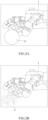
- FIGS. 2A and 2B are diagrams illustrating an operating principle of the robotic hand 11 according to an example embodiment
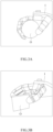
- FIGS. 3A and 3B are diagrams illustrating a motion of the robotic hand 11 according to an example embodiment
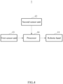
- FIG. 4 is a block diagram illustrating the robotic hand system 1 according to an example embodiment.
- the robotic hand system 1 may infer a motion of the robotic hand 11 conforming to an intention of a user, and operate the robotic hand 11 according to the inferred motion.
- the robotic hand system 1 may include a robotic hand 11, a first sensor unit 12, a second sensor unit 13, and a processor 14.
- the robotic hand 11 may grip a target object O.
- the robotic hand 11 may include a finger module 111, and the finger module 111 may include a plurality of frames 1111 and one or more joint portions 1112.
- the joint portion 1112 may be connected to the plurality of frames 1111, and may change positions of the plurality of frames 1111.
- the frame 1111 may be formed in a structure having a longitudinal direction.
- the joint portion 1112 may include one or more motors, and the position of the frame 1111 may be changed by rotation of the motor.
- the robotic hand 11 may function as a robotic prosthetic hand or industrial tongs.
- the robotic hand system 1 may be applied to various scales of use.
- the robotic hand system 1 may be applied to tip tongs of a heavy-duty crane, and the like.
- the finger module 111 may include a thumb finger portion 111a that performs a thumb finger function, an index finger portion 111b that performs an index finger function, a middle finger portion 111c that performs a middle finger function, a ring finger portion 111d that performs a ring finger function, and a little finger portion 111e that performs a little finger function.
- the thumb finger portion 111a may include two frames 1111 and two joint portions 1112.
- the index finger portion 111b, the middle finger portion 111c, the ring finger portion 111d, and the little finger portion 111e each may include three frames 1111 and three joint portions 1112.
- the thumb finger portion 111a may be formed so as to have a length in a longitudinal direction shorter than those of the index finger portion 11 1b, the middle finger portion 111c, the ring finger portion 111d, and the little finger portion 111e.
- the first sensor unit 12 may be disposed on the robotic hand 11, and may detect a real-time posture of the robotic hand 11. In an example embodiment, the first sensor unit 12 may detect the real-time posture of the robotic hand 11 in a manner of tracking a position of the second sensor unit 13 to be described later.
- the first sensor unit 12 may be disposed on an inner side of the robotic hand 11.
- the inner side refers to a position where a palm is formed, that is, a position formed on a back surface of the back of a hand.
- the above description is an example, and arrangement of the first sensor unit is not limited thereto.
- the second sensor unit 13 may be disposed on the robotic hand 11, and may detect three-dimensional surface information of the target object O that appears based on the robotic hand 11.
- the second sensor unit 13 may be provided in plurality.
- Each second sensor unit 13 may be disposed on an inner side of each of the thumb finger portion 1 1 1a, the index finger portion 11 1b, the middle finger portion 111c, the ring finger portion 111d, and the little finger portion 111e.
- the inner side refers to a position where a palm is formed, that is, a position formed on a back side of the back of a hand.
- the second sensor unit 13 may detect the three-dimensional surface information of the target object O without obstruction of a field of view, while the thumb finger portion 111a, the index finger portion 111b, the middle finger portion 111c, the ring finger portion 111d, and the little finger portion 111e surround the target object O.
- the processor 14 may infer, based on sensing information of the first sensor unit 12 and the second sensor unit 13, a motion of the robotic hand 11 conforming to the intention of the user, and may operate the robotic hand 11 according to the inferred motion. Since the processor 14 does not go through an image processing process, a computational complexity may be reduced, thereby remarkably improving a computation speed.
- the processor 14 may form, based on the sensing information of the first sensor unit 12 and the second sensor unit 13, a point cloud C with respect to a shape of a three-dimensional surface of the target object O. In an example embodiment, the processor 14 may determine, based on the point cloud C, a relative position of the robotic hand 11 in a relationship with the target object O. The processor 14 may determine, based on the relative position of the robotic hand 11, an optimal path for operation of the inferred motion of the robotic hand 11.
- the processor 14 may operate, based on the sensing information of the first sensor unit 12 and the second sensor unit 13, the robotic hand 11 so as to conform to the intention of the user. For example, when the target object O enters deep within the robotic hand 11, the processor 14 may operate the robotic hand 11 so as to grip the target object O using the entire palm of the robotic hand 11, while the finger module 111 surrounds the target object O (for example, FIG. 3A ). In addition, for example, when the target object O is positioned adj acent to an end of the finger module 111, the processor 14 may operate the robotic hand 11 so as to grip the target object O using the end of the finger module 111 (for example, FIG. 3B ).
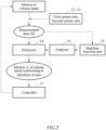
- FIG. 5 is a block diagram illustrating the robotic hand system 1 according to an example embodiment
- FIG. 6 is a block diagram illustrating a machine learning unit 15 of the robotic hand system 1 according to an example embodiment
- FIG. 7 is a block diagram illustrating an analyzer 16 of the robotic hand system 1 according to an example embodiment.
- a robotic hand system (for example, the robotic hand system 1 in FIG. 1 ) may diagnose a motion A of a robotic hand conforming to an intention of a user using machine learning.
- the robotic hand system 1 may further include a machine learning unit 15, an analyzer 16, and a controller 17.
- the robotic hand system 1 may learn a pattern P according to the motion A of the robotic hand conforming to the intention of the user through machine learning from learning data LD based on a first sensor unit (for example, the first sensor unit 12 in FIG. 1 ) and a second sensor unit (for example, the second sensor unit 13 in FIG 1 ) for which a motion of the robotic hand conforming to the intention of the user is known.
- the robotic hand system 1 may compare measurement data SD based on the sensing information of the first sensor unit 12 and the second sensor unit 13 with the pre-learned pattern P, and determine whether the pattern P is matched, and may determine a motion of the robotic hand corresponding to the matched pattern P as the motion A of the robotic hand conforming to the intention of the user.
- the robotic hand system 1 may operate the robotic hand 11 so as to conform to the intention of the user through feedback control that corrects the robotic hand (for example, the robotic hand 11 in FIG. 1 ) according to the motion A of the robotic hand conforming to the determined intention of the user.
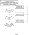
- the machine learning unit 15 may receive the learning data LD based on sensing information of the first sensor unit 12 and the second sensor unit 13 for which the motion of the robotic hand conforming to the intention of the user is known, and perform machine learning on the pattern P of the learning data LD. That is, the machine learning unit 15 may learn the pattern P of data generated according to the motion A of the robotic hand conforming to the intention of the user through supervised learning. Machine learning of the machine learning unit 15 may be pre-performed before a process is performed.
- the machine learning unit 15 may include a learning data acquisition unit 151, a pattern extractor 152, and a machine learning model generator 153.
- the learning data acquisition unit 151 may acquire each learning data LD according to the sensing information of the first sensor unit 12 and the second sensor unit 13 for which the motion A of the robotic hand conforming to the intention of the user is known.
- the learning data LD may be acquired for each motion A of the robotic hand conforming to an intention of each user. For example, data based on the sensing information of the first sensor unit 12 and the second sensor unit 13 having a first motion A1 may be acquired as first learning data LD1, and data based on the sensing information of the first sensor unit 12 and the second sensor unit 13 having a second motion A2 may be acquired as second learning data LD2.
- the learning data acquisition unit 151 may acquire data measured through a pre-experiment or acquire data from a database.
- the pattern extractor 152 may receive each learning data LD from the learning data acquisition unit 151. In the learning data LD sensed in a specific motion, a specific pattern P may be formed on the data due to the specific motion. The pattern extractor 152 may extract a pattern P of each data from each received learning data LD. The pattern P may be extracted for each learning data LD. For example, the pattern extractor 152 may extract a first pattern P1 from the first learning data LD1 and extract a second pattern P2 from the second learning data LD2. For example, the pattern extractor 152 may extract the pattern P by performing FFT processing on the learning data LD. Extraction of the pattern P by the pattern extractor152 may be performed through machine learning from a plurality of pieces of learning data LD based on the sensing information of the first sensor unit 12 and the second sensor unit 13 having the same motion.
- the machine learning model generator 153 may generate a machine learning model M by labeling the motion A of the robotic hand conforming to the intention of the user according to the sensing information of the first sensor unit 12 and the second sensor unit 13 corresponding to the extracted pattern P. That is, for each specific pattern P, the motion A of the robotic hand conforming to the corresponding intention of the user may be labeled and stored as the machine learning model M.
- the machine learning model M may include information indicating that a specific pattern P appears in data sensed in a specific motion, that is, information indicating that the robotic hand 11 operates with a specific motion when the specific pattern P appears in the sensed data.
- information on the first pattern P1 and the first motion A1 corresponding to the first pattern P1 may be stored in a first machine learning model M1
- information on the second pattern P2 and the second motion A2 corresponding to the second pattern P2 may be stored in a second machine learning model M2.
- the analyzer 16 may analyze the motion A of the robotic hand conforming to the intention of the user from the measurement data SD based on the sensing information of the first sensor unit 12 and the second sensor unit 13, using the pre-learned machine learning unit 15. The analyzer 16 may compare the measurement data SD with the pre-learned pattern P, and determine a motion of the robotic hand corresponding to the matched pattern P as the motion A of the robotic hand conforming to the intention of the user.
- the analyzer 16 may include a pattern matching unit 161 and a result output unit 162.
- the pattern matching unit 161 may compare the measurement data SD with the pattern P extracted by the pattern extractor 152, and determine whether the pattern P is matched. That is, the pattern matching unit 161 may determine the pattern P matching the measurement data SD. There may be a plurality of patterns P matching the measurement data SD. For example, the pattern matching unit 161 may determine whether the pattern P is matched by performing FFT processing on the measurement data SD. An operation of matching the measurement data SD with the pre-learned pattern P by the pattern matching unit 161 may be performed through machine learning.
- the result output unit 162 may search for the pattern P determined to be matched by the pattern matching unit 161 in the machine learning model M, and output a motion of the robotic hand as a result value. That is, the result output unit 162 may output a motion of the robotic hand corresponding to the pattern P matching the measurement data SD as the motion A of the robotic hand conforming to the intention of the user.
- the processor may perform feedback control on the motion of the robotic hand according to the result value of the result output unit 162.
- the processor 14 may correct and control the motion of the robotic hand so as to supplement the motion of the robotic hand. According to such feedback control, by correcting and controlling the motion of the robotic hand in real time according to the sensing information of the first sensor unit 12 and the second sensor unit 13, the robotic hand 11 may be operated so as to conform to the intention of the user.
- the controller 17 may receive the motion of the robotic hand 11 according to the intention of the user.
- the controller 17 may perform feedback control on the motion of the robotic hand 11 according to the motion A of the robotic hand conforming to the above-inferred intention of the user and a motion of the robotic hand 11 inputted through a controller.
- FIG. 8 is a flowchart illustrating a robotic hand control method 2 according to an example embodiment
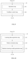
- FIG. 9 is a flowchart illustrating a machine learning step 25 for the robotic hand control method 2 according to an example embodiment
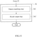
- FIG. 10 is a flowchart illustrating an analysis step 26 for the robotic hand control method 2 according to an example embodiment
- FIG. 11 is a flowchart illustrating a processing step 24 for the robotic hand control method 2 according to an example embodiment.
- the robotic hand control method 2 may diagnose a motion of a robotic hand conforming to an intention of a user using machine learning, and may perform feedback control on a mechanism portion according to a simple motion intention of a user inputted through a short-channel myopotential signal and the like, and the diagnosed necessary motion.
- the robotic hand control method 2 may include a robotic hand provision step 21, a first detection step 22, a second detection step 23, the processing step 24, the machine learning step 25, and the analysis step 26.
- the robotic hand provision step 21 may be a step of providing a robotic hand for gripping a target object.
- the first detection step 22 may be a step of detecting a real-time posture of the robotic hand.
- the second detection step 23 may be a step of detecting three-dimensional surface information of the target object that appears based on the robotic hand.
- the processing step 24 may be a step including an operation step 241 of inferring, based on information detected in the first detection step 22 and the second detection step 23, a motion of the robotic hand conforming to an intention of a user, and operating the robotic hand according to the inferred motion.
- the processing step 24 may further include a feedback control step 242 of performing feedback control on the robotic hand according to an outputted result value.
- the machine learning step 25 may be a step of receiving learning data based on the information detected in the first detection step 22 and the second detection step 23 for which the motion of the robotic hand conforming to the intention of the user is known, and performing machine learning on a pattern of the learning data.
- the machine learning step 25 may include a learning data acquisition step 251, a pattern extraction step 252, and a machine learning model generation step 253.
- the learning data acquisition step 251 may be a step of acquiring each learning data according to the information detected in the first detection step 22 and the second detection step 23 for which the motion of the robotic hand conforming to the intention of the user is known.
- the pattern extraction step 252 may be a step of extracting a pattern of each data from the learning data acquisition step 251.
- the machine learning model generation step 253 may be a step of generating a machine learning model by labeling the motion of the robotic hand conforming to the intention of the user according to the information detected in the first detection step 22 and the second detection step 23 corresponding to each extracted pattern.
- the analysis step 26 may be a step of analyzing the motion of the robotic hand conforming to the intention of the user from measurement data, using the machine learning model pre-learned through the machine learning step 25.
- the analysis step 26 may include a pattern matching step 261 and a result output step 262.
- the pattern matching step 261 may be a step of comparing the measurement data with the pattern extracted in the pattern extraction step 252, and determining whether the pattern is matched.
- the result output step 262 may be a step of searching for the pattern determined to be matched in the machine learning model, and outputting, as a result value, a motion of the robotic hand conforming to a corresponding intention of the user.
Landscapes
- Engineering & Computer Science (AREA)
- Mechanical Engineering (AREA)
- Robotics (AREA)
- Health & Medical Sciences (AREA)
- Human Computer Interaction (AREA)
- General Health & Medical Sciences (AREA)
- Transplantation (AREA)
- Orthopedic Medicine & Surgery (AREA)
- Automation & Control Theory (AREA)
- Veterinary Medicine (AREA)
- Oral & Maxillofacial Surgery (AREA)
- Public Health (AREA)
- Life Sciences & Earth Sciences (AREA)
- Vascular Medicine (AREA)
- Heart & Thoracic Surgery (AREA)
- Biomedical Technology (AREA)
- Animal Behavior & Ethology (AREA)
- Cardiology (AREA)
- Artificial Intelligence (AREA)
- Physics & Mathematics (AREA)
- Evolutionary Computation (AREA)
- Fuzzy Systems (AREA)
- Mathematical Physics (AREA)
- Software Systems (AREA)
- Manipulator (AREA)
Abstract
Description
- The following description relates to a robotic hand system and a method for controlling a robotic hand.
- In general, a disabled person having a part of the arm that is amputated wears a prosthetic hand on the amputated arm. Such a conventional prosthetic hand, which is simply worn on the arm by a wearing tool, has a short-coming in that it is not possible to provide a gripping force. In order to remedy the short-coming, an invention that provides a gripping force capable of gripping an object with a prosthetic hand by means of an electronic control device is being studied.
- There is a method in which a user presses a button corresponding to a desired posture before a prosthetic hand is operated to operate the prosthetic hand so as to correspond thereto, however, there is a problem in that it is non-intuitive because the user has to consciously send individual motion signals. In addition, there is a method of sensing a movement of a muscle of an affected part and operating a prosthetic hand so as to correspond thereto, however, there is a problem in that it is difficult to obtain various motion signals.
- Accordingly, there is a need for a robotic prosthetic hand system and method for controlling a robotic prosthetic hand that sense information on a target object to be gripped in real time so as to allow the target object to be automatically gripped.
- The above-described background technology is possessed or acquired by the inventor in a derivation process of the present invention, and is not necessarily a known technology disclosed to the general public prior to filing of the present application.
- An aspect provides a robotic hand system and a method for controlling a robotic hand that allow a target object to be efficiently gripped.
- Another aspect provides a system and method for controlling a robotic hand having a high success rate of gripping a target object.
- Still another aspect provides a system and method for controlling a robotic hand that are operable in an intuitive manner for a user.
- According to an aspect, there is provided a robotic hand system operated by a user, the robotic hand system including a robotic hand configured to grip a target object, a first sensor unit disposed on the robotic hand, the first sensor unit configured to detect a real-time posture of the robotic hand, a second sensor unit disposed on the robotic hand, the second sensor unit configured to detect three-dimensional surface information of the target object that appears based on the robotic hand, and a processor configured to infer, based on sensing information of the first sensor unit and the second sensor unit, a motion of the robotic hand conforming to an intention of the user, and operate the robotic hand according to the inferred motion. The robotic hand may include a finger module including a plurality of frames, and one or more joint portions connected to the plurality of frames, the one or more joint portions configured to change positions of the plurality of frames.
- The processor may be configured to form, based on the sensing information of the first sensor unit and the second sensor unit, a point cloud with respect to a shape of a three-dimensional surface of the target object.
- The processor may be configured to determine, based on the point cloud, a relative position of the robotic hand in a relationship with the target object.
- The processor may be configured to determine, based on the relative position of the robotic hand, an optimal path for operation of the inferred motion of the robotic hand.
- The robotic hand system may further include a machine learning unit configured to receive learning data based on the sensing information of the first sensor unit and the second sensor unit for which the motion of the robotic hand conforming to the intention of the user is known, and perform machine learning on a pattern of the learning data, and an analyzer configured to analyze, using the pre-learned machine learning unit, the motion of the robotic hand conforming to the intention of the user from measurement data based on the sensing information of the first sensor unit and the second sensor unit.
- The machine learning unit may include a learning data acquisition unit configured to acquire each learning data according to the sensing information of the first sensor unit and the second sensor unit for which the motion of the robotic hand conforming to the intention of the user is known, a pattern extractor configured to receive each learning data from the learning data acquisition unit, and extract a pattern of each data from each learning data, and a machine learning model generator configured to generate a machine learning model by labeling a motion of the robotic hand conforming to an intention of the user according to sensing information of the first sensor unit and the second sensor unit corresponding to each extracted pattern.
- The analyzer may include a pattern matching unit configured to compare the measurement data with the pattern extracted by the pattern extractor, and determine whether the pattern is matched, and a result output unit configured to search for the pattern determined to be matched by the pattern matching unit in the machine learning model, and output, as a result value, a motion of the robotic hand conforming to a corresponding intention of the user.
- The processor may be configured to perform feedback control on the robotic hand according to the result value of the result output unit.
- The finger module may include a thumb finger portion configured to perform a thumb finger function, an index finger portion configured to perform an index finger function, a middle finger portion configured to perform a middle finger function, a ring finger portion configured to perform a ring finger function, and a little finger portion configured to perform a little finger function.
- The thumb finger portion may include two frames and two joint portions, and the index finger portion, the middle finger portion, the ring finger portion, and the little finger portion each may include three frames and three joint portions.
- The second sensor unit may be provided in plurality, and each second sensor unit may be disposed on an inner side of each of the thumb finger portion, the index finger portion, the middle finger portion, the ring finger portion, and the little finger portion.
- According to another aspect, there is provided a method for controlling a robotic hand, the method including a robotic hand provision step of providing a robotic hand for gripping a target object, a first detection step of detecting a real-time posture of the robotic hand, a second detection step of detecting three-dimensional surface information of the target object that appears based on the robotic hand, a processing step including an operation step of inferring, based on information detected in the first detection step and the second sensor step, a motion of the robotic hand conforming to an intention of a user, and operating the robotic hand according to the inferred motion, a machine learning step of receiving learning data based on the information detected in the first detection step and the second detection step for which the motion of the robotic hand conforming to the intention of the user is known, and performing machine learning on a pattern of the learning data, and an analysis step of analyzing, using a machine learning model pre-learned through the machine learning step, the motion of the robotic hand conforming to the intention of the user from measurement data measured in the first detection step and the second detection step.
- The machine learning step may include a learning data acquisition step of acquiring each learning data according to the information detected in the first detection step and the second detection step for which the motion of the robotic hand conforming to the intention of the user is known, a pattern extraction step of extracting a pattern of each data from the learning data acquisition step, and a machine learning model generation step of generating a machine learning model by labeling a motion of the robotic hand conforming to an intention of the user according to information detected in the first detection step and the second detection step corresponding to each extracted pattern.
- The analysis step may include a pattern matching step of comparing the measurement data with the pattern extracted in the pattern extraction step, and determining whether the pattern is matched, and a result output step of searching for the pattern determined to be matched in the machine learning model, and outputting, as a result value, a motion of the robotic hand conforming to a corresponding intention of the user.
- The processing step may further include a feedback control step of performing feedback control on the robotic hand according to the outputted result value.
- A robotic hand system and method for controlling a robotic hand according to an aspect may efficiently grip a target object.
- The robotic hand system and method for controlling a robotic hand according to an aspect may grip the target object with high probability.
- The robotic hand system and method for controlling a robotic hand according to an aspect may be operated in an intuitive manner for a user.
- Effects of the robotic hand system and method for controlling a robotic hand according to an aspect are not limited to those mentioned above, and other effects not mentioned will be clearly understood by those skilled in the art from the following description.
- The following drawings attached to the present specification illustrate preferred example embodiments of the present invention, and serve to provide further understanding of the technical spirit of the present invention together with the detailed description of the invention, so that the present invention is not construed as being limited to the drawings.
-
FIG. 1 is a perspective view illustrating a robotic hand system according to an example embodiment. -
FIGS. 2A and 2B are diagrams illustrating an operating principle of a robotic hand according to an example embodiment. -
FIGS. 3A and 3B are diagrams illustrating a motion of a robotic hand according to an example embodiment. -
FIG. 4 is a block diagram illustrating a robotic hand system according to an example embodiment. -
FIG. 5 is a block diagram illustrating a robotic hand system according to an example embodiment. -
FIG. 6 is a block diagram illustrating a machine learning unit of a robotic hand system according to an example embodiment. -
FIG. 7 is a block diagram illustrating an analyzer of a robotic hand system according to an example embodiment. -
FIG. 8 is a flowchart illustrating a robotic hand control method according to an example embodiment. -
FIG. 9 is a flowchart illustrating a machine learning step for a robotic hand control method according to an example embodiment. -
FIG. 10 is a flowchart illustrating an analysis step for a robotic hand control method according to an example embodiment. -
FIG. 11 is a flowchart illustrating a processing step for a robotic hand control method according to an example embodiment. - Hereinafter, example embodiments are described in detail with reference to the accompanying drawings. Various modifications may be made to the example embodiments. The example embodiments are not construed as being limited to the disclosure and should be understood to include all changes, equivalents, and replacements within the idea and the technical scope of the disclosure.
- The terminology used herein is for the purpose of describing particular example embodiments only and is not to be limiting of the example embodiments. As used herein, the singular forms "a," "an," and "the" are intended to include the plural forms as well, unless the context clearly indicates otherwise. As used herein, the term "and/or" includes any one and any combination of any two or more of the associated listed items. It will be further understood that the terms "comprises" and/or "comprising," when used in this specification, specify the presence of stated features, integers, steps, operations, elements, components or a combination thereof, but do not preclude the presence or addition of one or more other features, integers, steps, operations, elements, components, and/or groups thereof.
- Unless otherwise defined herein, all terms used herein including technical or scientific terms have the same meanings as those generally understood by one of ordinary skill in the art. Terms defined in dictionaries generally used should be construed to have meanings matching contextual meanings in the related art and are not to be construed as an ideal or excessively formal meaning unless otherwise defined herein.
- In addition, when describing the example embodiments with reference to the accompanying drawings, like reference numerals refer to like components and a repeated description related thereto will be omitted. When describing the example embodiments, detailed description of well-known related structures or functions will be omitted when it is deemed that such description will cause ambiguous interpretation of the example embodiments.
- In addition, it will be understood that, although the terms first, second, A, B, (a), (b), and the like may be used herein to describe various components of the example embodiments, these terms are only used to distinguish one component from another component and essential, order, or sequence of corresponding components are not limited by these terms. It will be understood that when one component is referred to as being "connected to," "coupled to," or "linked to" another component, one component may be "connected to," "coupled to," or "linked to" another component via a further component although one component may be directly connected to or directly linked to another component.
- The same name may be used to describe a component included in an example embodiment and a component having a common function in another example embodiment. Unless otherwise mentioned, the description on the example embodiment may be applicable to the other example embodiment and thus, duplicated description will be omitted for conciseness.
-
FIG. 1 is a perspective view illustrating arobotic hand system 1 according to an example embodiment,FIGS. 2A and 2B are diagrams illustrating an operating principle of therobotic hand 11 according to an example embodiment,FIGS. 3A and 3B are diagrams illustrating a motion of therobotic hand 11 according to an example embodiment, andFIG. 4 is a block diagram illustrating therobotic hand system 1 according to an example embodiment. - Referring to
FIGS. 1 to 4 , therobotic hand system 1 according to an example embodiment may infer a motion of therobotic hand 11 conforming to an intention of a user, and operate therobotic hand 11 according to the inferred motion. In an example embodiment, therobotic hand system 1 may include arobotic hand 11, afirst sensor unit 12, asecond sensor unit 13, and aprocessor 14. - The
robotic hand 11 may grip a target object O. In an example embodiment, therobotic hand 11 may include afinger module 111, and thefinger module 111 may include a plurality offrames 1111 and one or morejoint portions 1112. Thejoint portion 1112 may be connected to the plurality offrames 1111, and may change positions of the plurality offrames 1111. For example, theframe 1111 may be formed in a structure having a longitudinal direction. For example, thejoint portion 1112 may include one or more motors, and the position of theframe 1111 may be changed by rotation of the motor. For example, therobotic hand 11 may function as a robotic prosthetic hand or industrial tongs. However, the above description is an example, and the function of the robotic hand is not limited thereto. In an example embodiment, therobotic hand system 1 may be applied to various scales of use. For example, therobotic hand system 1 may be applied to tip tongs of a heavy-duty crane, and the like. - In an example embodiment, the
finger module 111 may include athumb finger portion 111a that performs a thumb finger function, anindex finger portion 111b that performs an index finger function, amiddle finger portion 111c that performs a middle finger function, aring finger portion 111d that performs a ring finger function, and alittle finger portion 111e that performs a little finger function. Thethumb finger portion 111a may include twoframes 1111 and twojoint portions 1112. In addition, theindex finger portion 111b, themiddle finger portion 111c, thering finger portion 111d, and thelittle finger portion 111e each may include threeframes 1111 and threejoint portions 1112. For example, thethumb finger portion 111a may be formed so as to have a length in a longitudinal direction shorter than those of theindex finger portion 11 1b, themiddle finger portion 111c, thering finger portion 111d, and thelittle finger portion 111e. - The
first sensor unit 12 may be disposed on therobotic hand 11, and may detect a real-time posture of therobotic hand 11. In an example embodiment, thefirst sensor unit 12 may detect the real-time posture of therobotic hand 11 in a manner of tracking a position of thesecond sensor unit 13 to be described later. For example, thefirst sensor unit 12 may be disposed on an inner side of therobotic hand 11. Here, the inner side refers to a position where a palm is formed, that is, a position formed on a back surface of the back of a hand. However, the above description is an example, and arrangement of the first sensor unit is not limited thereto. - The
second sensor unit 13 may be disposed on therobotic hand 11, and may detect three-dimensional surface information of the target object O that appears based on therobotic hand 11. In an example embodiment, thesecond sensor unit 13 may be provided in plurality. Eachsecond sensor unit 13 may be disposed on an inner side of each of thethumb finger portion 1 1 1a, theindex finger portion 11 1b, themiddle finger portion 111c, thering finger portion 111d, and thelittle finger portion 111e. Here, the inner side refers to a position where a palm is formed, that is, a position formed on a back side of the back of a hand. Thesecond sensor unit 13 may detect the three-dimensional surface information of the target object O without obstruction of a field of view, while thethumb finger portion 111a, theindex finger portion 111b, themiddle finger portion 111c, thering finger portion 111d, and thelittle finger portion 111e surround the target object O. - The
processor 14 may infer, based on sensing information of thefirst sensor unit 12 and thesecond sensor unit 13, a motion of therobotic hand 11 conforming to the intention of the user, and may operate therobotic hand 11 according to the inferred motion. Since theprocessor 14 does not go through an image processing process, a computational complexity may be reduced, thereby remarkably improving a computation speed. - In
FIGS. 2A and 2B , in an example embodiment, theprocessor 14 may form, based on the sensing information of thefirst sensor unit 12 and thesecond sensor unit 13, a point cloud C with respect to a shape of a three-dimensional surface of the target object O. In an example embodiment, theprocessor 14 may determine, based on the point cloud C, a relative position of therobotic hand 11 in a relationship with the target object O. Theprocessor 14 may determine, based on the relative position of therobotic hand 11, an optimal path for operation of the inferred motion of therobotic hand 11. - In
FIGS. 3A and 3B , theprocessor 14 may operate, based on the sensing information of thefirst sensor unit 12 and thesecond sensor unit 13, therobotic hand 11 so as to conform to the intention of the user. For example, when the target object O enters deep within therobotic hand 11, theprocessor 14 may operate therobotic hand 11 so as to grip the target object O using the entire palm of therobotic hand 11, while thefinger module 111 surrounds the target object O (for example,FIG. 3A ). In addition, for example, when the target object O is positioned adj acent to an end of thefinger module 111, theprocessor 14 may operate therobotic hand 11 so as to grip the target object O using the end of the finger module 111 (for example,FIG. 3B ). -
FIG. 5 is a block diagram illustrating therobotic hand system 1 according to an example embodiment,FIG. 6 is a block diagram illustrating amachine learning unit 15 of therobotic hand system 1 according to an example embodiment, andFIG. 7 is a block diagram illustrating ananalyzer 16 of therobotic hand system 1 according to an example embodiment. - Referring to
FIGS. 5 to 7 , a robotic hand system (for example, therobotic hand system 1 inFIG. 1 ) according to an example embodiment may diagnose a motion A of a robotic hand conforming to an intention of a user using machine learning. In an example embodiment, therobotic hand system 1 may further include amachine learning unit 15, ananalyzer 16, and acontroller 17. - The
robotic hand system 1 may learn a pattern P according to the motion A of the robotic hand conforming to the intention of the user through machine learning from learning data LD based on a first sensor unit (for example, thefirst sensor unit 12 inFIG. 1 ) and a second sensor unit (for example, thesecond sensor unit 13 inFIG 1 ) for which a motion of the robotic hand conforming to the intention of the user is known. Therobotic hand system 1 may compare measurement data SD based on the sensing information of thefirst sensor unit 12 and thesecond sensor unit 13 with the pre-learned pattern P, and determine whether the pattern P is matched, and may determine a motion of the robotic hand corresponding to the matched pattern P as the motion A of the robotic hand conforming to the intention of the user. Therobotic hand system 1 may operate therobotic hand 11 so as to conform to the intention of the user through feedback control that corrects the robotic hand (for example, therobotic hand 11 inFIG. 1 ) according to the motion A of the robotic hand conforming to the determined intention of the user. - The
machine learning unit 15 may receive the learning data LD based on sensing information of thefirst sensor unit 12 and thesecond sensor unit 13 for which the motion of the robotic hand conforming to the intention of the user is known, and perform machine learning on the pattern P of the learning data LD. That is, themachine learning unit 15 may learn the pattern P of data generated according to the motion A of the robotic hand conforming to the intention of the user through supervised learning. Machine learning of themachine learning unit 15 may be pre-performed before a process is performed. - The
machine learning unit 15 may include a learningdata acquisition unit 151, apattern extractor 152, and a machinelearning model generator 153. - The learning
data acquisition unit 151 may acquire each learning data LD according to the sensing information of thefirst sensor unit 12 and thesecond sensor unit 13 for which the motion A of the robotic hand conforming to the intention of the user is known. The learning data LD may be acquired for each motion A of the robotic hand conforming to an intention of each user. For example, data based on the sensing information of thefirst sensor unit 12 and thesecond sensor unit 13 having a first motion A1 may be acquired as first learning data LD1, and data based on the sensing information of thefirst sensor unit 12 and thesecond sensor unit 13 having a second motion A2 may be acquired as second learning data LD2. The learningdata acquisition unit 151 may acquire data measured through a pre-experiment or acquire data from a database. - The
pattern extractor 152 may receive each learning data LD from the learningdata acquisition unit 151. In the learning data LD sensed in a specific motion, a specific pattern P may be formed on the data due to the specific motion. Thepattern extractor 152 may extract a pattern P of each data from each received learning data LD. The pattern P may be extracted for each learning data LD. For example, thepattern extractor 152 may extract a first pattern P1 from the first learning data LD1 and extract a second pattern P2 from the second learning data LD2. For example, thepattern extractor 152 may extract the pattern P by performing FFT processing on the learning data LD. Extraction of the pattern P by the pattern extractor152 may be performed through machine learning from a plurality of pieces of learning data LD based on the sensing information of thefirst sensor unit 12 and thesecond sensor unit 13 having the same motion. - The machine
learning model generator 153 may generate a machine learning model M by labeling the motion A of the robotic hand conforming to the intention of the user according to the sensing information of thefirst sensor unit 12 and thesecond sensor unit 13 corresponding to the extracted pattern P. That is, for each specific pattern P, the motion A of the robotic hand conforming to the corresponding intention of the user may be labeled and stored as the machine learning model M. The machine learning model M may include information indicating that a specific pattern P appears in data sensed in a specific motion, that is, information indicating that therobotic hand 11 operates with a specific motion when the specific pattern P appears in the sensed data. For example, information on the first pattern P1 and the first motion A1 corresponding to the first pattern P1 may be stored in a first machine learning model M1, and information on the second pattern P2 and the second motion A2 corresponding to the second pattern P2 may be stored in a second machine learning model M2. - The
analyzer 16 may analyze the motion A of the robotic hand conforming to the intention of the user from the measurement data SD based on the sensing information of thefirst sensor unit 12 and thesecond sensor unit 13, using the pre-learnedmachine learning unit 15. Theanalyzer 16 may compare the measurement data SD with the pre-learned pattern P, and determine a motion of the robotic hand corresponding to the matched pattern P as the motion A of the robotic hand conforming to the intention of the user. - The
analyzer 16 may include apattern matching unit 161 and aresult output unit 162. - The
pattern matching unit 161 may compare the measurement data SD with the pattern P extracted by thepattern extractor 152, and determine whether the pattern P is matched. That is, thepattern matching unit 161 may determine the pattern P matching the measurement data SD. There may be a plurality of patterns P matching the measurement data SD. For example, thepattern matching unit 161 may determine whether the pattern P is matched by performing FFT processing on the measurement data SD. An operation of matching the measurement data SD with the pre-learned pattern P by thepattern matching unit 161 may be performed through machine learning. - The
result output unit 162 may search for the pattern P determined to be matched by thepattern matching unit 161 in the machine learning model M, and output a motion of the robotic hand as a result value. That is, theresult output unit 162 may output a motion of the robotic hand corresponding to the pattern P matching the measurement data SD as the motion A of the robotic hand conforming to the intention of the user. - The processor (for example, the
processor 14 inFIG. 4 ) may perform feedback control on the motion of the robotic hand according to the result value of theresult output unit 162. Theprocessor 14 may correct and control the motion of the robotic hand so as to supplement the motion of the robotic hand. According to such feedback control, by correcting and controlling the motion of the robotic hand in real time according to the sensing information of thefirst sensor unit 12 and thesecond sensor unit 13, therobotic hand 11 may be operated so as to conform to the intention of the user. - The
controller 17 may receive the motion of therobotic hand 11 according to the intention of the user. Thecontroller 17 may perform feedback control on the motion of therobotic hand 11 according to the motion A of the robotic hand conforming to the above-inferred intention of the user and a motion of therobotic hand 11 inputted through a controller. -
FIG. 8 is a flowchart illustrating a robotichand control method 2 according to an example embodiment,FIG. 9 is a flowchart illustrating amachine learning step 25 for the robotichand control method 2 according to an example embodiment,FIG. 10 is a flowchart illustrating ananalysis step 26 for the robotichand control method 2 according to an example embodiment, andFIG. 11 is a flowchart illustrating aprocessing step 24 for the robotichand control method 2 according to an example embodiment. - Referring to
FIGS. 8 to 11 , the robotichand control method 2 according to an example embodiment may diagnose a motion of a robotic hand conforming to an intention of a user using machine learning, and may perform feedback control on a mechanism portion according to a simple motion intention of a user inputted through a short-channel myopotential signal and the like, and the diagnosed necessary motion. In an example embodiment, the robotichand control method 2 may include a robotichand provision step 21, afirst detection step 22, asecond detection step 23, theprocessing step 24, themachine learning step 25, and theanalysis step 26. - In describing the robotic
hand control method 2 with referenceFIGS. 8 and9 , a description overlapping the above description will be omitted. - The robotic
hand provision step 21 may be a step of providing a robotic hand for gripping a target object. Thefirst detection step 22 may be a step of detecting a real-time posture of the robotic hand. Thesecond detection step 23 may be a step of detecting three-dimensional surface information of the target object that appears based on the robotic hand. - The
processing step 24 may be a step including anoperation step 241 of inferring, based on information detected in thefirst detection step 22 and thesecond detection step 23, a motion of the robotic hand conforming to an intention of a user, and operating the robotic hand according to the inferred motion. In an example embodiment, theprocessing step 24 may further include afeedback control step 242 of performing feedback control on the robotic hand according to an outputted result value. - The
machine learning step 25 may be a step of receiving learning data based on the information detected in thefirst detection step 22 and thesecond detection step 23 for which the motion of the robotic hand conforming to the intention of the user is known, and performing machine learning on a pattern of the learning data. In an example embodiment, themachine learning step 25 may include a learningdata acquisition step 251, apattern extraction step 252, and a machine learningmodel generation step 253. - In an example embodiment, the learning
data acquisition step 251 may be a step of acquiring each learning data according to the information detected in thefirst detection step 22 and thesecond detection step 23 for which the motion of the robotic hand conforming to the intention of the user is known. Thepattern extraction step 252 may be a step of extracting a pattern of each data from the learningdata acquisition step 251. The machine learningmodel generation step 253 may be a step of generating a machine learning model by labeling the motion of the robotic hand conforming to the intention of the user according to the information detected in thefirst detection step 22 and thesecond detection step 23 corresponding to each extracted pattern. - The
analysis step 26 may be a step of analyzing the motion of the robotic hand conforming to the intention of the user from measurement data, using the machine learning model pre-learned through themachine learning step 25. In an example embodiment, theanalysis step 26 may include apattern matching step 261 and aresult output step 262. - In an example embodiment, the
pattern matching step 261 may be a step of comparing the measurement data with the pattern extracted in thepattern extraction step 252, and determining whether the pattern is matched. Theresult output step 262 may be a step of searching for the pattern determined to be matched in the machine learning model, and outputting, as a result value, a motion of the robotic hand conforming to a corresponding intention of the user. - A number of example embodiments have been described above. Nevertheless, it should be understood that various modifications may be made to these example embodiments. For example, suitable results may be achieved if the described techniques are performed in a different order and/or if components in a described system, architecture, device, or circuit are combined in a different manner and/or replaced or supplemented by other components or their equivalents.
- Accordingly, other implementations are within the scope of the following claims.
Claims (15)
- A robotic hand system operated by a user, the robotic hand system comprising:a robotic hand configured to grip a target object;a first sensor unit disposed on the robotic hand, the first sensor unit configured to detect a real-time posture of the robotic hand;a second sensor unit disposed on the robotic hand, the second sensor unit configured to detect three-dimensional surface information of the target object that appears based on the robotic hand; anda processor configured to infer, based on sensing information of the first sensor unit and the second sensor unit, a motion of the robotic hand conforming to an intention of the user, and operate the robotic hand according to the inferred motion,wherein the robotic hand comprises a finger module comprising:a plurality of frames; andone or more joint portions connected to the plurality of frames, the one or more joint portions configured to change positions of the plurality of frames.
- The robotic hand system of claim 1, wherein the processor is configured to form, based on the sensing information of the first sensor unit and the second sensor unit, a point cloud with respect to a shape of a three-dimensional surface of the target obj ect.
- The robotic hand system of claim 2, wherein the processor is configured to determine, based on the point cloud, a relative position of the robotic hand in a relationship with the target object.
- The robotic hand system of claim 3, wherein the processor is configured to determine, based on the relative position of the robotic hand, an optimal path for operation of the inferred motion of the robotic hand.
- The robotic hand system of claim 1, further comprising:a machine learning unit configured to receive learning data based on the sensing information of the first sensor unit and the second sensor unit for which the motion of the robotic hand conforming to the intention of the user is known, and perform machine learning on a pattern of the learning data; andan analyzer configured to analyze, using the pre-learned machine learning unit, the motion of the robotic hand conforming to the intention of the user from measurement data based on the sensing information of the first sensor unit and the second sensor unit.
- The robotic hand system of claim 5, wherein the machine learning unit comprises:a learning data acquisition unit configured to acquire each learning data according to the sensing information of the first sensor unit and the second sensor unit for which the motion of the robotic hand conforming to the intention of the user is known;a pattern extractor configured to receive each learning data from the learning data acquisition unit, and extract a pattern of each data from each learning data; anda machine learning model generator configured to generate a machine learning model by labeling a motion of the robotic hand conforming to an intention of the user according to sensing information of the first sensor unit and the second sensor unit corresponding to each extracted pattern.
- The robotic hand system of claim 6, wherein the analyzer comprises:a pattern matching unit configured to compare the measurement data with the pattern extracted by the pattern extractor, and determine whether the pattern is matched; anda result output unit configured to search for the pattern determined to be matched by the pattern matching unit in the machine learning model, and output, as a result value, a motion of the robotic hand conforming to a corresponding intention of the user.
- The robotic hand system of claim 7, wherein the processor is configured to perform feedback control on the robotic hand according to the result value of the result output unit.
- The robotic hand system of claim 1, wherein the finger module comprises:a thumb finger portion configured to perform a thumb finger function;an index finger portion configured to perform an index finger function;a middle finger portion configured to perform a middle finger function;a ring finger portion configured to perform a ring finger function; anda little finger portion configured to perform a little finger function.
- The robotic hand system of claim 9, whereinthe thumb finger portion comprises two frames and two joint portions, andthe index finger portion, the middle finger portion, the ring finger portion, and the little finger portion each comprise three frames and three joint portions.
- The robotic hand system of claim 10, whereinthe second sensor unit is provided in plurality, andeach second sensor unit is disposed on an inner side of each of the thumb finger portion, the index finger portion, the middle finger portion, the ring finger portion, and the little finger portion.
- A method for controlling a robotic hand, the method comprising:a robotic hand provision step of providing a robotic hand for gripping a target obj ect;a first detection step of detecting a real-time posture of the robotic hand;a second detection step of detecting three-dimensional surface information of the target object that appears based on the robotic hand;a processing step including an operation step of inferring, based on information detected in the first detection step and the second sensor step, a motion of the robotic hand conforming to an intention of a user, and operating the robotic hand according to the inferred motion;a machine learning step of receiving learning data based on the information detected in the first detection step and the second detection step for which the motion of the robotic hand conforming to the intention of the user is known, and performing machine learning on a pattern of the learning data; andan analysis step of analyzing, using a machine learning model pre-learned through the machine learning step, the motion of the robotic hand conforming to the intention of the user from measurement data measured in the first detection step and the second detection step.
- The method of claim 12, wherein the machine learning step comprises:a learning data acquisition step of acquiring each learning data according to the information detected in the first detection step and the second detection step for which the motion of the robotic hand conforming to the intention of the user is known;a pattern extraction step of extracting a pattern of each data from the learning data acquisition step; anda machine learning model generation step of generating a machine learning model by labeling a motion of the robotic hand conforming to an intention of the user according to information detected in the first detection step and the second detection step corresponding to each extracted pattern.
- The method of claim 13, wherein the analysis step comprises:a pattern matching step of comparing the measurement data with the pattern extracted in the pattern extraction step, and determining whether the pattern is matched; anda result output step of searching for the pattern determined to be matched in the machine learning model, and outputting, as a result value, a motion of the robotic hand conforming to a corresponding intention of the user.
- The method of claim 14, wherein the processing step further comprises a feedback control step of performing feedback control on the robotic hand according to the outputted result value.
Applications Claiming Priority (2)
| Application Number | Priority Date | Filing Date | Title |
|---|---|---|---|
| KR1020210140212A KR102559105B1 (en) | 2021-10-20 | 2021-10-20 | Robotic hand system and method for controlling robotic hand |
| PCT/KR2021/017622 WO2023068440A1 (en) | 2021-10-20 | 2021-11-26 | Robot hand system and method for controlling robot hand |
Publications (2)
| Publication Number | Publication Date |
|---|---|
| EP4420843A1 true EP4420843A1 (en) | 2024-08-28 |
| EP4420843A4 EP4420843A4 (en) | 2025-08-27 |
Family
ID=86059224
Family Applications (1)
| Application Number | Title | Priority Date | Filing Date |
|---|---|---|---|
| EP21961528.3A Pending EP4420843A4 (en) | 2021-10-20 | 2021-11-26 | ROBOT HAND SYSTEM AND METHOD FOR CONTROLLING A ROBOT HAND |
Country Status (4)
| Country | Link |
|---|---|
| US (1) | US12544937B2 (en) |
| EP (1) | EP4420843A4 (en) |
| KR (1) | KR102559105B1 (en) |
| WO (1) | WO2023068440A1 (en) |
Families Citing this family (4)
| Publication number | Priority date | Publication date | Assignee | Title |
|---|---|---|---|---|
| KR20220131089A (en) * | 2021-03-19 | 2022-09-27 | 현대자동차주식회사 | Joint structure for robot and robot including the structure |
| US12314346B2 (en) | 2024-12-19 | 2025-05-27 | Digital Global Systems, Inc. | Systems and methods of sensor data fusion |
| US12479105B2 (en) | 2024-12-19 | 2025-11-25 | Digital Global Systems, Inc | Systems and methods of sensor data fusion |
| US12487564B2 (en) | 2024-12-19 | 2025-12-02 | Digital Global Systems, Inc. | Systems and methods of sensor data fusion |
Family Cites Families (17)
| Publication number | Priority date | Publication date | Assignee | Title |
|---|---|---|---|---|
| US9114030B2 (en) | 2007-02-06 | 2015-08-25 | Deka Products Limited Partnership | System for control of a prosthetic device |
| KR101479232B1 (en) * | 2008-05-13 | 2015-01-06 | 삼성전자 주식회사 | Robot, robot hand, control method of robot hand |
| US9174339B2 (en) | 2010-11-22 | 2015-11-03 | Vanderbilt University | Control system for a grasping device |
| ES2661538T3 (en) | 2013-06-12 | 2018-04-02 | Otto Bock Healthcare Gmbh | Limb device control |
| US10609359B2 (en) | 2016-06-22 | 2020-03-31 | Intel Corporation | Depth image provision apparatus and method |
| US10773382B2 (en) | 2017-09-15 | 2020-09-15 | X Development Llc | Machine learning methods and apparatus for robotic manipulation and that utilize multi-task domain adaptation |
| JP6676030B2 (en) * | 2017-11-20 | 2020-04-08 | 株式会社安川電機 | Grasping system, learning device, gripping method, and model manufacturing method |
| US10682774B2 (en) | 2017-12-12 | 2020-06-16 | X Development Llc | Sensorized robotic gripping device |
| US10792809B2 (en) | 2017-12-12 | 2020-10-06 | X Development Llc | Robot grip detection using non-contact sensors |
| GB2574596A (en) * | 2018-06-08 | 2019-12-18 | Epic Inventing Inc | Prosthetic device |
| KR20200063353A (en) * | 2018-11-23 | 2020-06-05 | 강기준 | Multi-functional Electronic Prosthetic Hand using cameras and artificial intelligence |
| KR102178013B1 (en) | 2019-02-08 | 2020-11-12 | 한양대학교 산학협력단 | Training data generation method and pose determination method for grasping object |
| US20210122045A1 (en) * | 2019-10-24 | 2021-04-29 | Nvidia Corporation | In-hand object pose tracking |
| AU2021231896A1 (en) | 2020-03-06 | 2022-09-22 | The Feinstein Institutes For Medical Research | System and Method for Determining User Intention From Limb or Body Motion or Trajectory to Control Neuromuscular Stimulation or Prosthetic Device Operation |
| US12099645B2 (en) * | 2021-03-03 | 2024-09-24 | Guardian Glass, LLC | Systems and/or methods for creating and passively detecting changes in electrical fields |
| US20240149458A1 (en) * | 2021-03-31 | 2024-05-09 | Honda Motor Co., Ltd. | Robot remote operation control device, robot remote operation control system, robot remote operation control method, and program |
| US12564962B2 (en) * | 2021-03-31 | 2026-03-03 | Honda Motor Co., Ltd. | Robot remote operation control device, robot remote operation control system, robot remote operation control method, and non-transitory computer readable medium |
-
2021
- 2021-10-20 KR KR1020210140212A patent/KR102559105B1/en active Active
- 2021-11-26 US US17/622,160 patent/US12544937B2/en active Active
- 2021-11-26 EP EP21961528.3A patent/EP4420843A4/en active Pending
- 2021-11-26 WO PCT/KR2021/017622 patent/WO2023068440A1/en not_active Ceased
Also Published As
| Publication number | Publication date |
|---|---|
| KR102559105B1 (en) | 2023-07-26 |
| EP4420843A4 (en) | 2025-08-27 |
| US20230256618A1 (en) | 2023-08-17 |
| KR20230056321A (en) | 2023-04-27 |
| US12544937B2 (en) | 2026-02-10 |
| WO2023068440A1 (en) | 2023-04-27 |
| KR102559105B9 (en) | 2024-04-08 |
Similar Documents
| Publication | Publication Date | Title |
|---|---|---|
| US12544937B2 (en) | Robotic hand system and method for controlling robotic hand | |
| CN104238562B (en) | For the method and apparatus via wearable sensors control machine people's device | |
| Mohandes | Recognition of two-handed arabic signs using the cyberglove | |
| Yan et al. | Detection of slip from vision and touch | |
| Cockbum et al. | Grasp stability assessment through unsupervised feature learning of tactile images | |
| Back et al. | Control a contact sensing finger for surface haptic exploration | |
| CN110991292A (en) | Action recognition comparison method, system, computer storage medium and electronic device | |
| CN119188759B (en) | Automatic control system and method for mechanical arm of automatic assembly line | |
| US12564962B2 (en) | Robot remote operation control device, robot remote operation control system, robot remote operation control method, and non-transitory computer readable medium | |
| JP2021045810A (en) | Motion information generation device, end effector, robot and robot system | |
| CN112743537A (en) | Annotating device | |
| Luo et al. | Surface recognition via force-sensory walking-pattern classification for biped robot | |
| Begalinova et al. | Self-supervised learning of object slippage: An LSTM model trained on low-cost tactile sensors | |
| JP7798483B2 (en) | Robot remote operation control device, robot remote operation control system, robot remote operation control method, and program | |
| Sakr et al. | On the estimation of isometric wrist/forearm torque about three axes using force myography | |
| Ayral et al. | Spectro-temporal recurrent neural network for robotic slip detection with piezoelectric tactile sensor | |
| JP3601279B2 (en) | Parts assembly equipment | |
| CN113552945B (en) | Man-machine interaction glove system | |
| KR101882490B1 (en) | Robot and control method for the same | |
| Prakash et al. | Comprehensive analysis of an EMG based human-robot interface using various machine learning techniques | |
| Long et al. | Reinforcement Learning-Based Grasping via One-Shot Affordance Localization and Zero-Shot Contrastive Language-Image Learning | |
| JP2022157123A (en) | Robot remote operation control device, robot remote operation control system, robot remote operation control method and program | |
| JP7247571B2 (en) | Control device and learning device | |
| Triesch et al. | Towards imitation learning of grasping movements by an autonomous robot | |
| JP7565849B2 (en) | ROBOT REMOTE OPERATION CONTROL DEVICE, ROBOT REMOTE OPERATION CONTROL SYSTEM, ROBOT REMOTE OPERATION CONTROL METHOD, AND PROGRAM |
Legal Events
| Date | Code | Title | Description |
|---|---|---|---|
| STAA | Information on the status of an ep patent application or granted ep patent |
Free format text: STATUS: THE INTERNATIONAL PUBLICATION HAS BEEN MADE |
|
| PUAI | Public reference made under article 153(3) epc to a published international application that has entered the european phase |
Free format text: ORIGINAL CODE: 0009012 |
|
| STAA | Information on the status of an ep patent application or granted ep patent |
Free format text: STATUS: REQUEST FOR EXAMINATION WAS MADE |
|
| 17P | Request for examination filed |
Effective date: 20240516 |
|
| AK | Designated contracting states |
Kind code of ref document: A1 Designated state(s): AL AT BE BG CH CY CZ DE DK EE ES FI FR GB GR HR HU IE IS IT LI LT LU LV MC MK MT NL NO PL PT RO RS SE SI SK SM TR |
|
| DAV | Request for validation of the european patent (deleted) | ||
| DAX | Request for extension of the european patent (deleted) | ||
| A4 | Supplementary search report drawn up and despatched |
Effective date: 20250728 |
|
| RIC1 | Information provided on ipc code assigned before grant |
Ipc: B25J 15/00 20060101AFI20250722BHEP Ipc: B25J 15/10 20060101ALI20250722BHEP Ipc: B25J 13/08 20060101ALI20250722BHEP Ipc: A61F 2/58 20060101ALI20250722BHEP Ipc: A61F 2/70 20060101ALI20250722BHEP Ipc: B25J 9/16 20060101ALI20250722BHEP |