EP4420785A1 - Temperature control device - Google Patents
Temperature control device Download PDFInfo
- Publication number
- EP4420785A1 EP4420785A1 EP21966583.3A EP21966583A EP4420785A1 EP 4420785 A1 EP4420785 A1 EP 4420785A1 EP 21966583 A EP21966583 A EP 21966583A EP 4420785 A1 EP4420785 A1 EP 4420785A1
- Authority
- EP
- European Patent Office
- Prior art keywords
- temperature control
- cover portion
- control device
- temperature
- thermally conductive
- Prior art date
- Legal status (The legal status is an assumption and is not a legal conclusion. Google has not performed a legal analysis and makes no representation as to the accuracy of the status listed.)
- Pending
Links
Images



Classifications
-
- B—PERFORMING OPERATIONS; TRANSPORTING
- B01—PHYSICAL OR CHEMICAL PROCESSES OR APPARATUS IN GENERAL
- B01L—CHEMICAL OR PHYSICAL LABORATORY APPARATUS FOR GENERAL USE
- B01L7/00—Heating or cooling apparatus; Heat insulating devices
- B01L7/04—Heat insulating devices, e.g. jackets for flasks
-
- G—PHYSICS
- G01—MEASURING; TESTING
- G01N—INVESTIGATING OR ANALYSING MATERIALS BY DETERMINING THEIR CHEMICAL OR PHYSICAL PROPERTIES
- G01N1/00—Sampling; Preparing specimens for investigation
- G01N1/28—Preparing specimens for investigation including physical details of (bio-)chemical methods covered elsewhere, e.g. G01N33/50, C12Q
- G01N1/44—Sample treatment involving radiation, e.g. heat
-
- B—PERFORMING OPERATIONS; TRANSPORTING
- B01—PHYSICAL OR CHEMICAL PROCESSES OR APPARATUS IN GENERAL
- B01L—CHEMICAL OR PHYSICAL LABORATORY APPARATUS FOR GENERAL USE
- B01L7/00—Heating or cooling apparatus; Heat insulating devices
- B01L7/52—Heating or cooling apparatus; Heat insulating devices with provision for submitting samples to a predetermined sequence of different temperatures, e.g. for treating nucleic acid samples
-
- C—CHEMISTRY; METALLURGY
- C12—BIOCHEMISTRY; BEER; SPIRITS; WINE; VINEGAR; MICROBIOLOGY; ENZYMOLOGY; MUTATION OR GENETIC ENGINEERING
- C12M—APPARATUS FOR ENZYMOLOGY OR MICROBIOLOGY; APPARATUS FOR CULTURING MICROORGANISMS FOR PRODUCING BIOMASS, FOR GROWING CELLS OR FOR OBTAINING FERMENTATION OR METABOLIC PRODUCTS, i.e. BIOREACTORS OR FERMENTERS
- C12M1/00—Apparatus for enzymology or microbiology
-
- B—PERFORMING OPERATIONS; TRANSPORTING
- B01—PHYSICAL OR CHEMICAL PROCESSES OR APPARATUS IN GENERAL
- B01L—CHEMICAL OR PHYSICAL LABORATORY APPARATUS FOR GENERAL USE
- B01L2200/00—Solutions for specific problems relating to chemical or physical laboratory apparatus
- B01L2200/14—Process control and prevention of errors
- B01L2200/143—Quality control, feedback systems
- B01L2200/147—Employing temperature sensors
-
- B—PERFORMING OPERATIONS; TRANSPORTING
- B01—PHYSICAL OR CHEMICAL PROCESSES OR APPARATUS IN GENERAL
- B01L—CHEMICAL OR PHYSICAL LABORATORY APPARATUS FOR GENERAL USE
- B01L2300/00—Additional constructional details
- B01L2300/18—Means for temperature control
-
- B—PERFORMING OPERATIONS; TRANSPORTING
- B01—PHYSICAL OR CHEMICAL PROCESSES OR APPARATUS IN GENERAL
- B01L—CHEMICAL OR PHYSICAL LABORATORY APPARATUS FOR GENERAL USE
- B01L2300/00—Additional constructional details
- B01L2300/18—Means for temperature control
- B01L2300/1805—Conductive heating, heat from thermostatted solids is conducted to receptacles, e.g. heating plates, blocks
- B01L2300/1822—Conductive heating, heat from thermostatted solids is conducted to receptacles, e.g. heating plates, blocks using Peltier elements
-
- B—PERFORMING OPERATIONS; TRANSPORTING
- B01—PHYSICAL OR CHEMICAL PROCESSES OR APPARATUS IN GENERAL
- B01L—CHEMICAL OR PHYSICAL LABORATORY APPARATUS FOR GENERAL USE
- B01L2300/00—Additional constructional details
- B01L2300/18—Means for temperature control
- B01L2300/1883—Means for temperature control using thermal insulation
-
- B—PERFORMING OPERATIONS; TRANSPORTING
- B01—PHYSICAL OR CHEMICAL PROCESSES OR APPARATUS IN GENERAL
- B01L—CHEMICAL OR PHYSICAL LABORATORY APPARATUS FOR GENERAL USE
- B01L2300/00—Additional constructional details
- B01L2300/18—Means for temperature control
- B01L2300/1894—Cooling means; Cryo cooling
Definitions
- the present invention relates to a temperature control device.
- the genetic testing device that fully automatically implements extraction of a sample containing Deoxyribonucleic acid (DNA), mixing of reagents, amplification and testing of the DNA.
- the genetic testing device generally includes a temperature control device that keeps a sample or a reagent at a low temperature.
- Patent Literature 1 discloses a sample thermostatic device including a sample rack having a plurality of through holes into which sample bottles are loaded from an upper surface side, and a rack holder including a cooling element such as a Peltier element and a good thermally conductive material in contact with the element.
- Patent Literature 1 described above proposes a method in which a discharge pipe for discharging accumulated dew condensation water is provided on a bottom surface side of the rack holder.
- the temperature control device disclosed in Patent Literature 1 described above since the good thermally conductive material is also brought into contact with a lower surface of the sample rack, the sample rack itself is also likely to be cooled, and the dew condensation occurs on an upper surface of the sample rack. Therefore, in the temperature control device disclosed in Patent Literature 1, a sample may be contaminated, and testing accuracy may decrease due to splashing of the dew condensation water when inserting and removing a sample bottle.
- the invention has been made to solve such problems, and an object thereof is to provide a temperature control device that prevents occurrence of dew condensation on an upper surface of a cover portion.
- a temperature control device including: a thermally conductive portion; a cooling part configured to cool the thermally conductive portion; and a cover portion having an opening through which a container is inserted and removed while covering an upper side of the thermally conductive portion, in which an air layer is formed between the thermally conductive portion and the cover portion.
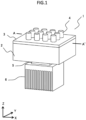
- FIG. 1 is a schematic perspective view showing a temperature control device 1 according to Embodiment 1.
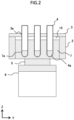
- FIG. 2 is a cross-sectional view taken along a line A-A' in FIG. 1 .
- the temperature control device 1 according to the present embodiment includes a temperature control block 7 (thermally conductive portion), a temperature control part 5 (cooling part) that cools the temperature control block 7, and a cover portion 3 that covers an upper side of the temperature control block 7.
- the temperature control block 7 is formed of aluminum, and has a plurality of concave portions 7a for holding sample containers 4.
- the material of the temperature control block 7 is not limited to aluminum as long as it is a metal having high thermal conductivity, and copper, magnesium alloy, and the like can also be used. It is desirable that a depth of the concave portion 7a formed in the temperature control block 7 is larger than a liquid surface height of a solution 4a in order to satisfactorily maintain cooling performance of the solution 4a contained in the sample container 4.
- a temperature sensor is disposed in the temperature control block 7.
- the temperature control part 5 is a Peltier element in contact with a lower surface of the temperature control block 7.
- the Peltier element has a function of adjusting a temperature of the solution 4a in the sample container 4 to a predetermined temperature by cooling the temperature control block 7, and specifically, adjusts an output such that a temperature measured by the temperature sensor in the temperature control block 7 becomes the predetermined temperature.
- a heat dissipation part 6 that dissipates the heat is required.
- the heat dissipation part 6 has a structure that dissipates heat to outside air by a fin or a fan.
- the temperature control part 5 is not limited to the Peltier element, and may introduce cold water or hot water from a heat pump, a chiller, or the like, or may have a structure that combines a plurality of these components.
- the cover portion 3 has an opening portion 3a for inserting and removing the sample container 4 such that a horizontal position coincides with that of the concave portion 7a provided in the temperature control block 7.
- the sample container 4 inserted through the opening portion 3a of the cover portion 3 is supported by the concave portion 7a of the temperature control block 7.
- the cover portion 3 is formed of a material having thermal conductivity lower than that of the temperature control block 7, for example, resin or rubber.
- the cover portion 3 does not need to be formed of only one kind of material, and may be formed of a combination of two or more kinds of materials.
- the temperature control device 1 includes a heat insulation material 2 that covers a lateral side of the temperature control block 7.
- the heat insulation material 2 is, for example, a foam heat insulation material, and has a heat insulation performance higher than that of the cover portion 3. Therefore, different from an upper end surface of the temperature control block 7, an upper end surface of the heat insulation material 2 is in contact with the cover portion 3.
- an air layer 10 formed between the temperature control block 7 and the cover portion 3 will be described. As shown in FIG. 2 , the upper end surface of the temperature control block 7 and a lower surface of the cover portion 3 are separated from each other, and a space is defined by the temperature control block 7, the heat insulation material 2, and the cover portion 3 (and the sample containers 4).
- the air layer 10 existing in the space serves as a heat insulation layer, and prevents heat of the cover portion 3 from being transmitted to the temperature control block 7. Therefore, in the temperature control device 1, even if the temperature control block 7 is cooled to a temperature lower than that of the outside air, a surface temperature of the cover portion 3 exposed to the outside air is maintained higher than a temperature of the temperature control block 7.
- a desirable thickness of the air layer 10 will be examined.
- a general resin material is used for the cover portion 3, a thickness thereof is 5 mm, and thermal conductivity thereof is 0.2 W/m•K, that is, thermal resistance is 2.5 K/W.
- a temperature of the outside air is 30 °C, and humidity of the outside air is 800, that is, a dew point temperature of the outside air is 26.2 °C.
- thermal conductivity of the air layer 10 is 0.026 W/m•K
- a heat transfer coefficient due to natural convection from a surface of the temperature control block 7 to air is simply 15 W/m2•K
- a surface area of the temperature control block 7 is 0.01m2.
- a set temperature of the temperature control block 7 is 15 °C.
- a thermal resistance of the air layer 10 is 19.2 K/W, and an equivalent thermal resistance to the air due to the natural convection is 6.67 K/W.
- the surface temperature of the cover portion 3 is calculated based on the values of the thermal resistances, it is estimated to be 26.5 °C. That is, since the surface temperature of the cover portion 3 is higher than the dew point temperature of the outside air of 26.2 °C, it is possible to prevent occurrence of the dew condensation on the upper surface of the cover portion 3.
- the desirable thickness of the air layer 10 varies depending on the material and the thickness of the cover portion 3, the set temperature of the temperature control block 7, and the like, but an upper limit value may be 10 mm.
- an upper limit value may be 10 mm. The reason for this is that when the air layer 10 is thicker than 10 mm, heat transfer due to natural convection in the air layer 10 may increase, and cooling of the cover portion 3 may proceed excessively.
- the lower surface of the cover portion 3 (a surface facing the temperature control block 7) and the upper end surface of the temperature control block 7 (a surface facing the cover portion 3) are formed of materials having low emissivity, whereby it is also possible to prevent an influence of heat transfer due to radiation between the cover portion 3 and the temperature control block 7.
- the air layer 10 exists between the temperature control block 7 and the cover portion 3, a decrease in the surface temperature of the cover portion 3 is prevented, and it is possible to prevent occurrence of the dew condensation on the upper surface of the cover portion 3.
- outside air containing water vapor other than the air that exists in advance as the air layer 10 is not supplied to the upper end surface of the temperature control block 7, an amount of dew condensation that occurs on the upper end surface of the temperature control block 7 can also be reduced.
- the cover portion 3 and the heat insulation material 2 may not be formed separately, and may be formed integrally with common foam or the like. Even if the cover portion 3 is formed of a material having high heat insulation performance such as foam, as compared with a side surface, it is difficult to thicken the upper surface, and existence of the dew condensation is likely to influence inserting and removing the sample container 4. Therefore, the air layer 10 that separates the upper end surface of the temperature control block 7 from the lower surface of the cover portion 3 is required.
- the air layer 10 is not limited to a single layer, and may have a structure in which a plurality of layers are stacked in an upper-lower direction. Further, in order to improve airtightness of the air layer 10, an elastic member such as packing may be provided on an inner peripheral surface of the opening portion 3a of the cover portion 3, and a gap with the sample container 4 may be reduced.
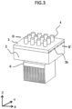
- FIG. 3 is a schematic perspective view showing the temperature control device 1 according to Embodiment 2.
- FIG. 4 is a schematic side view showing the temperature control device 1 according to Embodiment 2.
- a plurality of convex portions 3b that extend in a left-right direction (x direction) are provided on the lower surface of the cover portion 3 in a front-rear direction (y direction).
- the convex portion 3b may extend in the front-rear direction as long as the convex portion 3b is provided between the adjacent opening portions 3a.
- the convex portion 3b may protrude as a result by making a periphery concave.
- FIG. 5 is a cross-sectional view taken along a line B-B' in FIG. 3 .
- FIG. 6 is an enlarged cross-sectional view showing the convex portion 3b in FIG. 5 in an enlarged manner.
- a height h2 of the convex portion 3b near an edge in the left-right direction is larger than a height h1 of the convex portion 3b near a center in the left-right direction. That is, the convex portion 3b that protrudes downward from the cover portion 3 is lower from a center side toward an edge side.
- the convex portion 3b having such a shape is provided on the lower surface of the cover portion 3, whereby dew condensation water generated due to water vapor contained in the air layer 10 is led to an edge where a gap with the temperature control block 7 is small by a capillary phenomenon.
- a hydrophilic treatment is performed on the convex portions 3b of the cover portion 3, discharging the dew condensation water by the capillary phenomenon may be further promoted.
- the dew condensation water led to the edge by the convex portion 3b may be guided to a separately provided storage portion or discharging portion, but even if the dew condensation water only accumulates on the edge, the dew condensation water is located at a place away from the opening portion 3a. Therefore, it is possible to prevent splashing of the dew condensation water when inserting and removing the sample container 4. That is, even if the dew condensation water is generated on the upper end surface of the temperature control block 7, contamination of a sample due to the splashing of the dew condensation water can be prevented, and a decrease in testing accuracy can be prevented.
- the convex portions may be provided on the upper end surface of the temperature control block 7 to discharge the dew condensation water, but since the dew condensation water may accumulate between the convex portions, it is desirable that the convex portions are provided on the lower surface of the cover portion 3.
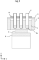
- FIG. 7 is a schematic cross-sectional view showing the temperature control device 1 according to Embodiment 3, and corresponds to FIG. 2 in Embodiment 1.
- the temperature control device 1 includes a heating part 11 that heats the cover portion 3.
- the heating part 11 include a ceramic heater, a film heater, and a Peltier element.
- a temperature sensor is provided in the cover portion 3 (not shown). Therefore, the heating part 11 can prevent occurrence of the dew condensation on the upper surface of the cover portion 3 by performing control such that the upper surface of the cover portion 3 is not at the dew point temperature or lower based on a measured temperature of the temperature sensor.
- the temperature control device 1 includes a sensor that measures a temperature and a humidity of the outside air
- a dew point temperature of the outside air may be specifically calculated, and the heating part 11 may be controlled to exceed the calculated dew point temperature.
- the dew point temperature of the outside air cannot be specifically calculated, a dew point temperature under conditions where the dew condensation is likely to occur can be assumed, and the heating part 11 can also be controlled to exceed the dew point temperature.
- the heating part 11 according to the present embodiment is provided on the upper surface of the cover portion 3 far from the temperature control block 7, deterioration of performance of cooling the sample container 4 is also prevented.
- the place where the heating part 11 is provided is not limited to the upper surface of the cover portion 3, and the heating part 11 may be provided on the lower surface of the cover portion 3 or outside of the heat insulation material 2.
- the heating part 11 according to the present embodiment does not need to be provided on the entire upper surface of the cover portion 3.
- a material having high thermal conductivity for example, a metal material such as copper, aluminum, or stainless steel, or a graphite sheet
- the entire upper surface of the cover portion 3 can be uniformly heated only by bringing the heating part 11 into contact with only a part of the cover portion 3.
- FIG. 8 is a schematic cross-sectional view showing the temperature control device 1 according to Embodiment 4, and corresponds to FIG. 2 in Embodiment 1 and FIG. 7 in Embodiment 3.
- the temperature control device 1 according to the present embodiment includes a heat transfer connection portion 12 that transfers heat from the heat dissipation part 6 to the upper surface of the cover portion 3.
- One end of the heat transfer connection portion 12 is in contact with the heat dissipation part 6, and the other end of the heat transfer connection portion 12 is in contact with the cover portion 3.
- the heat dissipation part 6 and the cover portion 3 are thermally connected, and heat generated by the temperature control part 5 is used to heat the cover portion 3, whereby it is possible to prevent the dew condensation on the upper surface of the cover portion 3.
- the heat transfer connection portion 12 is preferably formed of a material having high thermal conductivity, and desirably formed of aluminum, copper, graphite, or the like.
- a heat transfer area is increased, and heating the cover portion 3 can also be further promoted.
- a heat pipe may be adopted as the heat transfer connection portion 12.
- the heat transfer connection portion 12 may be connected not only to the heat dissipation part 6, but also to another heat source, for example, a power supply that drives the temperature control device 1, or a semiconductor element provided on a control board of a genetic testing device, and heat of the heat source may be conducted to the cover portion 3.
Landscapes
- Health & Medical Sciences (AREA)
- Chemical & Material Sciences (AREA)
- Life Sciences & Earth Sciences (AREA)
- General Health & Medical Sciences (AREA)
- Chemical Kinetics & Catalysis (AREA)
- Biochemistry (AREA)
- Clinical Laboratory Science (AREA)
- Engineering & Computer Science (AREA)
- Bioinformatics & Cheminformatics (AREA)
- Molecular Biology (AREA)
- Wood Science & Technology (AREA)
- Biotechnology (AREA)
- Organic Chemistry (AREA)
- Zoology (AREA)
- Analytical Chemistry (AREA)
- Physics & Mathematics (AREA)
- Pathology (AREA)
- Immunology (AREA)
- General Physics & Mathematics (AREA)
- Genetics & Genomics (AREA)
- Biomedical Technology (AREA)
- Medicinal Chemistry (AREA)
- Sustainable Development (AREA)
- General Engineering & Computer Science (AREA)
- Microbiology (AREA)
- Testing Resistance To Weather, Investigating Materials By Mechanical Methods (AREA)
- Automatic Analysis And Handling Materials Therefor (AREA)
- Control Of Temperature (AREA)
- Sampling And Sample Adjustment (AREA)
Abstract
Description
- The present invention relates to a temperature control device.
- There is a genetic testing device that fully automatically implements extraction of a sample containing Deoxyribonucleic acid (DNA), mixing of reagents, amplification and testing of the DNA. The genetic testing device generally includes a temperature control device that keeps a sample or a reagent at a low temperature.
- For example,
Patent Literature 1 discloses a sample thermostatic device including a sample rack having a plurality of through holes into which sample bottles are loaded from an upper surface side, and a rack holder including a cooling element such as a Peltier element and a good thermally conductive material in contact with the element. - PTL 1:
JPH10-192719A - In a related-art temperature control device, when cooling a sample or the like, dew condensation may occur due to ambient temperature and humidity, or a temperature of a cooling part. For example,
Patent Literature 1 described above proposes a method in which a discharge pipe for discharging accumulated dew condensation water is provided on a bottom surface side of the rack holder. However, in the temperature control device disclosed inPatent Literature 1 described above, since the good thermally conductive material is also brought into contact with a lower surface of the sample rack, the sample rack itself is also likely to be cooled, and the dew condensation occurs on an upper surface of the sample rack. Therefore, in the temperature control device disclosed inPatent Literature 1, a sample may be contaminated, and testing accuracy may decrease due to splashing of the dew condensation water when inserting and removing a sample bottle. - The invention has been made to solve such problems, and an object thereof is to provide a temperature control device that prevents occurrence of dew condensation on an upper surface of a cover portion.
- Provided is a temperature control device including: a thermally conductive portion; a cooling part configured to cool the thermally conductive portion; and a cover portion having an opening through which a container is inserted and removed while covering an upper side of the thermally conductive portion, in which an air layer is formed between the thermally conductive portion and the cover portion.
- According to the invention, it is possible to provide a temperature control device that prevents occurrence of dew condensation on an upper surface of a cover portion. Problems, configurations, and effects other than those described above will be made clear by the following description.
-
- [
FIG. 1] FIG. 1 is a schematic perspective view showing a temperature control device according toEmbodiment 1. - [
FIG. 2] FIG. 2 is a cross-sectional view taken along a line A-A' inFIG. 1 . - [
FIG. 3] FIG. 3 is a schematic perspective view showing a temperature control device according toEmbodiment 2. - [
FIG. 4] FIG. 4 is a schematic side view showing the temperature control device according toEmbodiment 2. - [
FIG. 5] FIG. 5 is a cross-sectional view taken along a line B-B' inFIG. 3 . - [
FIG. 6] FIG. 6 is an enlarged cross-sectional view showing a shape of a convex portion inFIG. 5 in an enlarged manner. - [
FIG. 7] FIG. 7 is a schematic cross-sectional view showing a temperature control device according toEmbodiment 3. - [
FIG. 8] FIG. 8 is a schematic cross-sectional view showing a temperature control device according toEmbodiment 4. - Hereinafter, embodiments of the invention will be described using Embodiments 1 to 4.
-
FIG. 1 is a schematic perspective view showing atemperature control device 1 according toEmbodiment 1.FIG. 2 is a cross-sectional view taken along a line A-A' inFIG. 1 . As shown inFIGS. 1 and2 , thetemperature control device 1 according to the present embodiment includes a temperature control block 7 (thermally conductive portion), a temperature control part 5 (cooling part) that cools thetemperature control block 7, and acover portion 3 that covers an upper side of thetemperature control block 7. - Here, the
temperature control block 7 is formed of aluminum, and has a plurality ofconcave portions 7a for holdingsample containers 4. However, the material of thetemperature control block 7 is not limited to aluminum as long as it is a metal having high thermal conductivity, and copper, magnesium alloy, and the like can also be used. It is desirable that a depth of theconcave portion 7a formed in thetemperature control block 7 is larger than a liquid surface height of asolution 4a in order to satisfactorily maintain cooling performance of thesolution 4a contained in thesample container 4. In addition, although not shown, a temperature sensor is disposed in thetemperature control block 7. - The
temperature control part 5 is a Peltier element in contact with a lower surface of thetemperature control block 7. The Peltier element has a function of adjusting a temperature of thesolution 4a in thesample container 4 to a predetermined temperature by cooling thetemperature control block 7, and specifically, adjusts an output such that a temperature measured by the temperature sensor in thetemperature control block 7 becomes the predetermined temperature. However, since the Peltier element generates heat when thetemperature control block 7 is cooled, aheat dissipation part 6 that dissipates the heat is required. Although not shown, theheat dissipation part 6 has a structure that dissipates heat to outside air by a fin or a fan. Thetemperature control part 5 is not limited to the Peltier element, and may introduce cold water or hot water from a heat pump, a chiller, or the like, or may have a structure that combines a plurality of these components. - The
cover portion 3 has anopening portion 3a for inserting and removing thesample container 4 such that a horizontal position coincides with that of theconcave portion 7a provided in thetemperature control block 7. Thesample container 4 inserted through theopening portion 3a of thecover portion 3 is supported by theconcave portion 7a of thetemperature control block 7. It is desirable that thecover portion 3 is formed of a material having thermal conductivity lower than that of thetemperature control block 7, for example, resin or rubber. In addition, thecover portion 3 does not need to be formed of only one kind of material, and may be formed of a combination of two or more kinds of materials. - The
temperature control device 1 according to the present embodiment includes aheat insulation material 2 that covers a lateral side of thetemperature control block 7. Theheat insulation material 2 is, for example, a foam heat insulation material, and has a heat insulation performance higher than that of thecover portion 3. Therefore, different from an upper end surface of thetemperature control block 7, an upper end surface of theheat insulation material 2 is in contact with thecover portion 3. - Next, an
air layer 10 formed between thetemperature control block 7 and thecover portion 3 will be described. As shown inFIG. 2 , the upper end surface of thetemperature control block 7 and a lower surface of thecover portion 3 are separated from each other, and a space is defined by thetemperature control block 7, theheat insulation material 2, and the cover portion 3 (and the sample containers 4). Theair layer 10 existing in the space serves as a heat insulation layer, and prevents heat of thecover portion 3 from being transmitted to thetemperature control block 7. Therefore, in thetemperature control device 1, even if thetemperature control block 7 is cooled to a temperature lower than that of the outside air, a surface temperature of thecover portion 3 exposed to the outside air is maintained higher than a temperature of thetemperature control block 7. That is, even if a temperature of thetemperature control block 7 is a temperature lower than a dew point of the outside air, since the surface temperature of thecover portion 3 is maintained at a temperature higher than the dew point of the outside air, dew condensation is unlikely to occur on an upper surface of thecover portion 3. - Here, a desirable thickness of the
air layer 10 will be examined. As a premise, it is assumed that a general resin material is used for thecover portion 3, a thickness thereof is 5 mm, and thermal conductivity thereof is 0.2 W/m•K, that is, thermal resistance is 2.5 K/W. Further, as conditions under which the dew condensation is likely to occur, it is assumed that a temperature of the outside air is 30 °C, and humidity of the outside air is 800, that is, a dew point temperature of the outside air is 26.2 °C. Further, it is assumed that thermal conductivity of theair layer 10 is 0.026 W/m•K, a heat transfer coefficient due to natural convection from a surface of thetemperature control block 7 to air is simply 15 W/m2•K, and a surface area of thetemperature control block 7 is 0.01m2. In addition, it is assumed that a set temperature of thetemperature control block 7 is 15 °C. - Under such preconditions, when the thickness of the
air layer 10 is 5 mm, a thermal resistance of theair layer 10 is 19.2 K/W, and an equivalent thermal resistance to the air due to the natural convection is 6.67 K/W. When the surface temperature of thecover portion 3 is calculated based on the values of the thermal resistances, it is estimated to be 26.5 °C. That is, since the surface temperature of thecover portion 3 is higher than the dew point temperature of the outside air of 26.2 °C, it is possible to prevent occurrence of the dew condensation on the upper surface of thecover portion 3. - The desirable thickness of the
air layer 10 varies depending on the material and the thickness of thecover portion 3, the set temperature of thetemperature control block 7, and the like, but an upper limit value may be 10 mm. The reason for this is that when theair layer 10 is thicker than 10 mm, heat transfer due to natural convection in theair layer 10 may increase, and cooling of thecover portion 3 may proceed excessively. - In the examination described above, only the natural convection in the
air layer 10 is considered, but actually, it is also necessary to consider an influence of heat transfer due to radiation. Therefore, the lower surface of the cover portion 3 (a surface facing the temperature control block 7) and the upper end surface of the temperature control block 7 (a surface facing the cover portion 3) are formed of materials having low emissivity, whereby it is also possible to prevent an influence of heat transfer due to radiation between thecover portion 3 and thetemperature control block 7. For example, it is considered to metal-plate the lower surface of thecover portion 3, or stack thin metal plates or films. - As described above, according to the present embodiment, since the
air layer 10 exists between thetemperature control block 7 and thecover portion 3, a decrease in the surface temperature of thecover portion 3 is prevented, and it is possible to prevent occurrence of the dew condensation on the upper surface of thecover portion 3. In addition, since outside air containing water vapor other than the air that exists in advance as theair layer 10 is not supplied to the upper end surface of thetemperature control block 7, an amount of dew condensation that occurs on the upper end surface of thetemperature control block 7 can also be reduced. - The
cover portion 3 and theheat insulation material 2 may not be formed separately, and may be formed integrally with common foam or the like. Even if thecover portion 3 is formed of a material having high heat insulation performance such as foam, as compared with a side surface, it is difficult to thicken the upper surface, and existence of the dew condensation is likely to influence inserting and removing thesample container 4. Therefore, theair layer 10 that separates the upper end surface of thetemperature control block 7 from the lower surface of thecover portion 3 is required. In addition, theair layer 10 is not limited to a single layer, and may have a structure in which a plurality of layers are stacked in an upper-lower direction. Further, in order to improve airtightness of theair layer 10, an elastic member such as packing may be provided on an inner peripheral surface of theopening portion 3a of thecover portion 3, and a gap with thesample container 4 may be reduced. -
FIG. 3 is a schematic perspective view showing thetemperature control device 1 according toEmbodiment 2.FIG. 4 is a schematic side view showing thetemperature control device 1 according toEmbodiment 2. As shown inFIGS. 3 and4 , in thetemperature control device 1 according to the present embodiment, a plurality ofconvex portions 3b that extend in a left-right direction (x direction) are provided on the lower surface of thecover portion 3 in a front-rear direction (y direction). Theconvex portion 3b may extend in the front-rear direction as long as theconvex portion 3b is provided between theadjacent opening portions 3a. In addition, theconvex portion 3b may protrude as a result by making a periphery concave. -
FIG. 5 is a cross-sectional view taken along a line B-B' inFIG. 3 .FIG. 6 is an enlarged cross-sectional view showing theconvex portion 3b inFIG. 5 in an enlarged manner. As shown inFIGS. 5 and6 , a height h2 of theconvex portion 3b near an edge in the left-right direction is larger than a height h1 of theconvex portion 3b near a center in the left-right direction. That is, theconvex portion 3b that protrudes downward from thecover portion 3 is lower from a center side toward an edge side. Theconvex portion 3b having such a shape is provided on the lower surface of thecover portion 3, whereby dew condensation water generated due to water vapor contained in theair layer 10 is led to an edge where a gap with thetemperature control block 7 is small by a capillary phenomenon. Here, when a hydrophilic treatment is performed on theconvex portions 3b of thecover portion 3, discharging the dew condensation water by the capillary phenomenon may be further promoted. - The dew condensation water led to the edge by the
convex portion 3b may be guided to a separately provided storage portion or discharging portion, but even if the dew condensation water only accumulates on the edge, the dew condensation water is located at a place away from theopening portion 3a. Therefore, it is possible to prevent splashing of the dew condensation water when inserting and removing thesample container 4. That is, even if the dew condensation water is generated on the upper end surface of thetemperature control block 7, contamination of a sample due to the splashing of the dew condensation water can be prevented, and a decrease in testing accuracy can be prevented. The convex portions may be provided on the upper end surface of thetemperature control block 7 to discharge the dew condensation water, but since the dew condensation water may accumulate between the convex portions, it is desirable that the convex portions are provided on the lower surface of thecover portion 3. -
FIG. 7 is a schematic cross-sectional view showing thetemperature control device 1 according toEmbodiment 3, and corresponds toFIG. 2 inEmbodiment 1. As shown inFIG. 7 , thetemperature control device 1 according to the present embodiment includes aheating part 11 that heats thecover portion 3. Examples of theheating part 11 include a ceramic heater, a film heater, and a Peltier element. In addition, a temperature sensor is provided in the cover portion 3 (not shown). Therefore, theheating part 11 can prevent occurrence of the dew condensation on the upper surface of thecover portion 3 by performing control such that the upper surface of thecover portion 3 is not at the dew point temperature or lower based on a measured temperature of the temperature sensor. - Here, when the
temperature control device 1 includes a sensor that measures a temperature and a humidity of the outside air, a dew point temperature of the outside air may be specifically calculated, and theheating part 11 may be controlled to exceed the calculated dew point temperature. When the dew point temperature of the outside air cannot be specifically calculated, a dew point temperature under conditions where the dew condensation is likely to occur can be assumed, and theheating part 11 can also be controlled to exceed the dew point temperature. - Since the
heating part 11 according to the present embodiment is provided on the upper surface of thecover portion 3 far from thetemperature control block 7, deterioration of performance of cooling thesample container 4 is also prevented. However, the place where theheating part 11 is provided is not limited to the upper surface of thecover portion 3, and theheating part 11 may be provided on the lower surface of thecover portion 3 or outside of theheat insulation material 2. - The
heating part 11 according to the present embodiment does not need to be provided on the entire upper surface of thecover portion 3. For example, when at least the upper surface of thecover portion 3 is formed of a material having high thermal conductivity (for example, a metal material such as copper, aluminum, or stainless steel, or a graphite sheet), the entire upper surface of thecover portion 3 can be uniformly heated only by bringing theheating part 11 into contact with only a part of thecover portion 3. -
FIG. 8 is a schematic cross-sectional view showing thetemperature control device 1 according toEmbodiment 4, and corresponds toFIG. 2 inEmbodiment 1 andFIG. 7 inEmbodiment 3. As shown inFIG. 8 , thetemperature control device 1 according to the present embodiment includes a heattransfer connection portion 12 that transfers heat from theheat dissipation part 6 to the upper surface of thecover portion 3. One end of the heattransfer connection portion 12 is in contact with theheat dissipation part 6, and the other end of the heattransfer connection portion 12 is in contact with thecover portion 3. In this way, theheat dissipation part 6 and thecover portion 3 are thermally connected, and heat generated by thetemperature control part 5 is used to heat thecover portion 3, whereby it is possible to prevent the dew condensation on the upper surface of thecover portion 3. - The heat
transfer connection portion 12 is preferably formed of a material having high thermal conductivity, and desirably formed of aluminum, copper, graphite, or the like. Here, when the heattransfer connection portion 12 has a shape with a large cross-sectional area, such as a plate shape, a heat transfer area is increased, and heating thecover portion 3 can also be further promoted. In addition, a heat pipe may be adopted as the heattransfer connection portion 12. Further, the heattransfer connection portion 12 may be connected not only to theheat dissipation part 6, but also to another heat source, for example, a power supply that drives thetemperature control device 1, or a semiconductor element provided on a control board of a genetic testing device, and heat of the heat source may be conducted to thecover portion 3. - The examples described above are described in detail in order to describe the invention in an easy-to-understand manner, and are not necessarily limited to including all the described configurations. Further, a part of a configuration of a certain example can also be replaced with a configuration of another example, and a configuration of another example can also be added to a configuration of a certain example. In addition, addition, deletion, and replacement of another configuration can also be made to a part of a configuration of each example.
-
- 1: temperature control device
- 2: heat insulation material
- 3: cover portion
- 3a: opening portion
- 3b: convex portion
- 4: sample container
- 4a: solution
- 5: temperature control part
- 6: heat dissipation part
- 7: temperature control block
- 7a: concave portion
- 10: air layer
- 11: heating part
- 12: heat transfer connection portion
Claims (5)
- A temperature control device comprising:a thermally conductive portion;a cooling part configured to cool the thermally conductive portion; anda cover portion having an opening through which a container is inserted and removed while covering an upper side of the thermally conductive portion, whereinan air layer is formed between the thermally conductive portion and the cover portion.
- The temperature control device according to claim 1, wherein
a thickness of the air layer is 10 mm or less. - The temperature control device according to claim 1, wherein
a convex portion lower from a center side toward an edge side is provided on a lower surface of the cover portion. - The temperature control device according to claim 1, further comprising:
a heating part configured to heat the cover portion. - The temperature control device according to claim 1, further comprising:a heat dissipation part configured to dissipate heat generated by the cooling part; anda heat transfer connection portion configured to transfer heat from the heat dissipation part to the cover portion.
Applications Claiming Priority (1)
| Application Number | Priority Date | Filing Date | Title |
|---|---|---|---|
| PCT/JP2021/044911 WO2023105627A1 (en) | 2021-12-07 | 2021-12-07 | Temperature control device |
Publications (2)
| Publication Number | Publication Date |
|---|---|
| EP4420785A1 true EP4420785A1 (en) | 2024-08-28 |
| EP4420785A4 EP4420785A4 (en) | 2025-08-27 |
Family
ID=86729904
Family Applications (1)
| Application Number | Title | Priority Date | Filing Date |
|---|---|---|---|
| EP21966583.3A Pending EP4420785A4 (en) | 2021-12-07 | 2021-12-07 | TEMPERATURE CONTROL DEVICE |
Country Status (7)
| Country | Link |
|---|---|
| US (1) | US20250027857A1 (en) |
| EP (1) | EP4420785A4 (en) |
| JP (1) | JP7724880B2 (en) |
| KR (1) | KR20240089597A (en) |
| CN (1) | CN118234570A (en) |
| TW (1) | TWI872396B (en) |
| WO (1) | WO2023105627A1 (en) |
Families Citing this family (1)
| Publication number | Priority date | Publication date | Assignee | Title |
|---|---|---|---|---|
| JP2026000706A (en) * | 2024-06-18 | 2026-01-06 | キヤノン株式会社 | Reactor and stabilizing member |
Family Cites Families (40)
| Publication number | Priority date | Publication date | Assignee | Title |
|---|---|---|---|---|
| JPH01137964A (en) * | 1987-11-24 | 1989-05-30 | Terumo Corp | Culture vessel |
| US6703236B2 (en) * | 1990-11-29 | 2004-03-09 | Applera Corporation | Thermal cycler for automatic performance of the polymerase chain reaction with close temperature control |
| DE29623597U1 (en) * | 1996-11-08 | 1999-01-07 | Eppendorf - Netheler - Hinz Gmbh, 22339 Hamburg | Temperature control block with temperature control devices |
| JPH10192719A (en) | 1997-01-08 | 1998-07-28 | Shimadzu Corp | Sample thermostat |
| CN101038863B (en) * | 2001-02-15 | 2011-07-06 | 东京毅力科创株式会社 | Method and apparatus for processing workpiece |
| JP4050627B2 (en) * | 2003-01-29 | 2008-02-20 | 重直 圓山 | Temperature control device with Peltier element |
| JP4492466B2 (en) * | 2005-07-11 | 2010-06-30 | 株式会社島津製作所 | Sample thermostat |
| JP4981295B2 (en) * | 2005-10-04 | 2012-07-18 | キヤノン株式会社 | DNA processing method and DNA processing apparatus |
| EP1898218A3 (en) * | 2006-09-05 | 2009-10-07 | FUJIFILM Corporation | Cold insulation unit and measurement apparatus |
| WO2008126827A1 (en) * | 2007-04-06 | 2008-10-23 | Universal Bio Research Co., Ltd. | Temperature control device, and temperature control method |
| CN103157400B (en) * | 2007-06-21 | 2014-12-24 | 简·探针公司 | Instrument and method for exposing container to multiple areas |
| JP2010075870A (en) * | 2008-09-26 | 2010-04-08 | Taitec Corp | Thermostat for physical and chemical test |
| US20100124766A1 (en) * | 2008-11-14 | 2010-05-20 | Life Technologies Corporation | Apparatus and Method for Segmented Thermal Cycler |
| JP5426993B2 (en) * | 2009-10-30 | 2014-02-26 | アークレイ株式会社 | Temperature control apparatus and temperature control method |
| KR102032523B1 (en) * | 2010-01-12 | 2019-10-15 | 아람 바이오시스템 주식회사 | Two-Stage Thermal Convection Apparatus And Uses Thereof |
| WO2011086497A2 (en) * | 2010-01-12 | 2011-07-21 | Ahram Biosystems, Inc. | Three-stage thermal convection apparatus and uses thereof |
| EP2560759B1 (en) * | 2010-04-20 | 2020-02-12 | QIAGEN GmbH | Temperature control method and apparatus |
| KR20120107716A (en) * | 2011-03-22 | 2012-10-04 | 삼성테크윈 주식회사 | Temperature control apparatus for material |
| JP5707253B2 (en) * | 2011-06-27 | 2015-04-22 | 株式会社日立ハイテクノロジーズ | Cold reagent storage and nucleic acid analyzer |
| US20130157376A1 (en) * | 2011-12-20 | 2013-06-20 | Idaho Technology, Inc. | Thermal Cycler Calibration Device and Related Methods |
| CN103205362B (en) * | 2012-01-16 | 2014-11-19 | 同济大学 | A PCR instrument with high temperature control precision |
| US9386948B2 (en) * | 2012-12-05 | 2016-07-12 | Theranos, Inc. | Systems, devices, and methods for bodily fluid sample transport |
| US11433397B2 (en) * | 2013-03-15 | 2022-09-06 | Becton, Dickinson And Company | Process tube and carrier tray |
| JP6410194B2 (en) * | 2014-07-24 | 2018-10-24 | 国立大学法人九州大学 | Temperature control module and light measurement device |
| WO2017112833A1 (en) * | 2015-12-22 | 2017-06-29 | Life Technologies Corporation | Thermal cycler systems and adaptor |
| US10758880B2 (en) * | 2016-05-04 | 2020-09-01 | Cem Corporation | Acid digestion instrument and vessel system |
| CN108205337A (en) * | 2016-12-19 | 2018-06-26 | 广州康昕瑞基因健康科技有限公司 | The insulation construction of blending instrument |
| US11077443B2 (en) * | 2017-02-02 | 2021-08-03 | University Of Wyoming | Apparatus for temperature modulation of samples |
| US11506675B2 (en) * | 2017-03-28 | 2022-11-22 | Hitachi High-Tech Corporation | Inspection device |
| JP6904131B2 (en) * | 2017-07-21 | 2021-07-14 | 株式会社島津製作所 | Gene measuring device |
| CN110892058B (en) * | 2017-09-29 | 2024-04-19 | 深圳华大智造科技股份有限公司 | Gene sequencing reaction equipment and gene sequencing system |
| CN111386154A (en) * | 2018-01-31 | 2020-07-07 | 株式会社岛津制作所 | Cooling and tempering vial holder and sample temperature adjusting device using the same |
| EP3599023B1 (en) * | 2018-07-24 | 2021-03-10 | F. Hoffmann-La Roche AG | A method to monitor and control the temperature of a sample holder of a laboratory instrument |
| DE102018124408A1 (en) * | 2018-10-02 | 2020-04-02 | Biometra GmbH | Device for the thermal treatment of samples |
| CN113287208B (en) * | 2019-01-14 | 2025-08-26 | 生物辐射实验室股份有限公司 | Heat pump equipment and components |
| EP3929273B1 (en) | 2019-02-18 | 2026-01-28 | Hitachi High-Tech Corporation | Cultivation container rack and analyzing device |
| DE102019106699B4 (en) * | 2019-03-15 | 2024-01-25 | Analytik Jena Gmbh+Co. Kg | Device and method for the thermal treatment of samples |
| CA3141275A1 (en) * | 2019-06-18 | 2020-12-24 | Biomeme, Inc. | Systems for sample analysis |
| CN112958179A (en) * | 2021-03-04 | 2021-06-15 | 南昌大学第二附属医院 | Kit for detecting endocrine metabolic diseases |
| AU2023242746A1 (en) * | 2022-03-29 | 2024-01-18 | Illumina, Inc. | Library preparation systems and methods |
-
2021
- 2021-12-07 EP EP21966583.3A patent/EP4420785A4/en active Pending
- 2021-12-07 WO PCT/JP2021/044911 patent/WO2023105627A1/en not_active Ceased
- 2021-12-07 CN CN202180104135.0A patent/CN118234570A/en active Pending
- 2021-12-07 JP JP2023565731A patent/JP7724880B2/en active Active
- 2021-12-07 KR KR1020247015638A patent/KR20240089597A/en not_active Ceased
- 2021-12-07 US US18/713,129 patent/US20250027857A1/en active Pending
-
2022
- 2022-11-23 TW TW111144718A patent/TWI872396B/en active
Also Published As
| Publication number | Publication date |
|---|---|
| EP4420785A4 (en) | 2025-08-27 |
| JPWO2023105627A1 (en) | 2023-06-15 |
| WO2023105627A1 (en) | 2023-06-15 |
| TW202324019A (en) | 2023-06-16 |
| TWI872396B (en) | 2025-02-11 |
| KR20240089597A (en) | 2024-06-20 |
| CN118234570A (en) | 2024-06-21 |
| US20250027857A1 (en) | 2025-01-23 |
| JP7724880B2 (en) | 2025-08-18 |
Similar Documents
| Publication | Publication Date | Title |
|---|---|---|
| EP1628771B2 (en) | Thermal cycling apparatus for providing thermal uniformity | |
| EP2076605B2 (en) | Cooling in a thermal cycler using heat pipes | |
| CN106133499B (en) | Sample holder for heating and temperature regulation and sample temperature regulation device using the same | |
| US11378496B2 (en) | Device with sample temperature adjustment function | |
| US11548007B2 (en) | Thermal cycler systems and methods of use | |
| US20220404299A1 (en) | High sample throughput differential scanning calorimeter | |
| JP5887022B2 (en) | Incubator | |
| US20250027857A1 (en) | Temperature control device | |
| ES2738665A1 (en) | Compact thermal cycling device and system comprising said thermal cycling device | |
| CN111386154A (en) | Cooling and tempering vial holder and sample temperature adjusting device using the same | |
| CN111492237B (en) | Sample temperature adjusting device for analyzer | |
| CN116555002A (en) | A rapid heating and cooling device for PCR | |
| JP2010075870A (en) | Thermostat for physical and chemical test | |
| EP2353722A1 (en) | Heat dissipation of power electronics for thermocyclers | |
| CN107796759B (en) | Optical measuring instrument | |
| WO2024252648A1 (en) | Liquid treatment device, nucleic acid extraction device, and gene testing device |
Legal Events
| Date | Code | Title | Description |
|---|---|---|---|
| STAA | Information on the status of an ep patent application or granted ep patent |
Free format text: STATUS: THE INTERNATIONAL PUBLICATION HAS BEEN MADE |
|
| PUAI | Public reference made under article 153(3) epc to a published international application that has entered the european phase |
Free format text: ORIGINAL CODE: 0009012 |
|
| STAA | Information on the status of an ep patent application or granted ep patent |
Free format text: STATUS: REQUEST FOR EXAMINATION WAS MADE |
|
| 17P | Request for examination filed |
Effective date: 20240521 |
|
| AK | Designated contracting states |
Kind code of ref document: A1 Designated state(s): AL AT BE BG CH CY CZ DE DK EE ES FI FR GB GR HR HU IE IS IT LI LT LU LV MC MK MT NL NO PL PT RO RS SE SI SK SM TR |
|
| DAV | Request for validation of the european patent (deleted) | ||
| DAX | Request for extension of the european patent (deleted) | ||
| A4 | Supplementary search report drawn up and despatched |
Effective date: 20250724 |
|
| RIC1 | Information provided on ipc code assigned before grant |
Ipc: B01L 7/04 20100101AFI20250718BHEP Ipc: C12M 1/00 20060101ALI20250718BHEP Ipc: B01L 7/00 20060101ALI20250718BHEP |