EP4420773A1 - Carbon dioxide adsorbent and carbon dioxide adsorption-desorption device - Google Patents
Carbon dioxide adsorbent and carbon dioxide adsorption-desorption device Download PDFInfo
- Publication number
- EP4420773A1 EP4420773A1 EP23209869.9A EP23209869A EP4420773A1 EP 4420773 A1 EP4420773 A1 EP 4420773A1 EP 23209869 A EP23209869 A EP 23209869A EP 4420773 A1 EP4420773 A1 EP 4420773A1
- Authority
- EP
- European Patent Office
- Prior art keywords
- carbon dioxide
- adsorbent
- dioxide adsorbent
- electrode
- cyclic disulfide
- Prior art date
- Legal status (The legal status is an assumption and is not a legal conclusion. Google has not performed a legal analysis and makes no representation as to the accuracy of the status listed.)
- Pending
Links
- CURLTUGMZLYLDI-UHFFFAOYSA-N Carbon dioxide Chemical compound O=C=O CURLTUGMZLYLDI-UHFFFAOYSA-N 0.000 title claims abstract description 433
- 229910002092 carbon dioxide Inorganic materials 0.000 title claims abstract description 242
- 239000001569 carbon dioxide Substances 0.000 title claims abstract description 240
- 239000003463 adsorbent Substances 0.000 title claims abstract description 155
- 238000002336 sorption--desorption measurement Methods 0.000 title claims description 36
- QVGXLLKOCUKJST-UHFFFAOYSA-N atomic oxygen Chemical compound [O] QVGXLLKOCUKJST-UHFFFAOYSA-N 0.000 claims description 29
- 239000001301 oxygen Substances 0.000 claims description 29
- 229910052760 oxygen Inorganic materials 0.000 claims description 29
- 238000006722 reduction reaction Methods 0.000 claims description 22
- 230000009467 reduction Effects 0.000 claims description 21
- 125000004122 cyclic group Chemical group 0.000 claims description 18
- 230000003647 oxidation Effects 0.000 claims description 16
- 238000007254 oxidation reaction Methods 0.000 claims description 16
- 125000001997 phenyl group Chemical group [H]C1=C([H])C([H])=C(*)C([H])=C1[H] 0.000 claims description 12
- 239000013310 covalent-organic framework Substances 0.000 claims description 11
- 230000033116 oxidation-reduction process Effects 0.000 claims description 10
- 230000004044 response Effects 0.000 claims description 10
- 125000001624 naphthyl group Chemical group 0.000 claims description 8
- 239000012621 metal-organic framework Substances 0.000 claims description 6
- 238000006479 redox reaction Methods 0.000 claims description 6
- 229920000642 polymer Polymers 0.000 claims description 5
- 125000000623 heterocyclic group Chemical group 0.000 claims description 3
- 125000000101 thioether group Chemical group 0.000 claims description 3
- 239000008151 electrolyte solution Substances 0.000 description 53
- 239000011148 porous material Substances 0.000 description 40
- 239000007789 gas Substances 0.000 description 33
- BWGNESOTFCXPMA-UHFFFAOYSA-N Dihydrogen disulfide Chemical compound SS BWGNESOTFCXPMA-UHFFFAOYSA-N 0.000 description 24
- -1 acyclic disulfide compound Chemical class 0.000 description 23
- 238000000034 method Methods 0.000 description 23
- 238000013459 approach Methods 0.000 description 18
- 238000001179 sorption measurement Methods 0.000 description 16
- OKTJSMMVPCPJKN-UHFFFAOYSA-N Carbon Chemical compound [C] OKTJSMMVPCPJKN-UHFFFAOYSA-N 0.000 description 13
- 239000002131 composite material Substances 0.000 description 13
- 239000002904 solvent Substances 0.000 description 13
- GUUVPOWQJOLRAS-UHFFFAOYSA-N Diphenyl disulfide Chemical compound C=1C=CC=CC=1SSC1=CC=CC=C1 GUUVPOWQJOLRAS-UHFFFAOYSA-N 0.000 description 12
- 230000000052 comparative effect Effects 0.000 description 12
- 238000011010 flushing procedure Methods 0.000 description 12
- 239000000243 solution Substances 0.000 description 12
- 239000003792 electrolyte Substances 0.000 description 11
- 238000005259 measurement Methods 0.000 description 11
- 229910052799 carbon Inorganic materials 0.000 description 10
- WEVYAHXRMPXWCK-UHFFFAOYSA-N Acetonitrile Chemical compound CC#N WEVYAHXRMPXWCK-UHFFFAOYSA-N 0.000 description 9
- GYVHEQGWDJVMAU-UHFFFAOYSA-N benzo[c][1,2]benzodithiine Chemical compound C1=CC=C2SSC3=CC=CC=C3C2=C1 GYVHEQGWDJVMAU-UHFFFAOYSA-N 0.000 description 9
- 238000006243 chemical reaction Methods 0.000 description 9
- 238000002484 cyclic voltammetry Methods 0.000 description 9
- 238000004519 manufacturing process Methods 0.000 description 9
- 238000001069 Raman spectroscopy Methods 0.000 description 8
- WYURNTSHIVDZCO-UHFFFAOYSA-N Tetrahydrofuran Chemical compound C1CCOC1 WYURNTSHIVDZCO-UHFFFAOYSA-N 0.000 description 8
- 150000001875 compounds Chemical class 0.000 description 8
- 238000003795 desorption Methods 0.000 description 8
- RUOJZAUFBMNUDX-UHFFFAOYSA-N propylene carbonate Chemical compound CC1COC(=O)O1 RUOJZAUFBMNUDX-UHFFFAOYSA-N 0.000 description 8
- PXHVJJICTQNCMI-UHFFFAOYSA-N Nickel Chemical compound [Ni] PXHVJJICTQNCMI-UHFFFAOYSA-N 0.000 description 7
- 230000015572 biosynthetic process Effects 0.000 description 7
- 239000000126 substance Substances 0.000 description 7
- 125000001424 substituent group Chemical group 0.000 description 7
- 238000003786 synthesis reaction Methods 0.000 description 7
- 238000012360 testing method Methods 0.000 description 7
- XLYOFNOQVPJJNP-UHFFFAOYSA-N water Chemical group O XLYOFNOQVPJJNP-UHFFFAOYSA-N 0.000 description 7
- CLCPDSJUXHDRGX-UHFFFAOYSA-N 6-(1,3-dihydroxyisobutyl)thymine Chemical compound CC1=C(CC(CO)CO)NC(=O)NC1=O CLCPDSJUXHDRGX-UHFFFAOYSA-N 0.000 description 6
- 239000011230 binding agent Substances 0.000 description 6
- 230000005587 bubbling Effects 0.000 description 6
- 238000004364 calculation method Methods 0.000 description 6
- ZUOUZKKEUPVFJK-UHFFFAOYSA-N diphenyl Chemical compound C1=CC=CC=C1C1=CC=CC=C1 ZUOUZKKEUPVFJK-UHFFFAOYSA-N 0.000 description 6
- 238000010438 heat treatment Methods 0.000 description 6
- 238000011084 recovery Methods 0.000 description 6
- 150000003839 salts Chemical class 0.000 description 6
- 238000000926 separation method Methods 0.000 description 6
- YRHRIQCWCFGUEQ-UHFFFAOYSA-N thioxanthen-9-one Chemical compound C1=CC=C2C(=O)C3=CC=CC=C3SC2=C1 YRHRIQCWCFGUEQ-UHFFFAOYSA-N 0.000 description 6
- NDOFGUDEKQECDN-UHFFFAOYSA-N 1,2-dithiaacenaphthene Chemical compound C1=CC2=CC=CC(SS3)=C2C3=C1 NDOFGUDEKQECDN-UHFFFAOYSA-N 0.000 description 5
- 125000003277 amino group Chemical group 0.000 description 5
- 230000000694 effects Effects 0.000 description 5
- 239000011261 inert gas Substances 0.000 description 5
- 229910052751 metal Inorganic materials 0.000 description 5
- 239000002184 metal Substances 0.000 description 5
- 230000008569 process Effects 0.000 description 5
- 230000006798 recombination Effects 0.000 description 5
- 238000005215 recombination Methods 0.000 description 5
- 238000001644 13C nuclear magnetic resonance spectroscopy Methods 0.000 description 4
- XKRFYHLGVUSROY-UHFFFAOYSA-N Argon Chemical compound [Ar] XKRFYHLGVUSROY-UHFFFAOYSA-N 0.000 description 4
- VEXZGXHMUGYJMC-UHFFFAOYSA-N Hydrochloric acid Chemical compound Cl VEXZGXHMUGYJMC-UHFFFAOYSA-N 0.000 description 4
- 239000002033 PVDF binder Substances 0.000 description 4
- 229910052782 aluminium Inorganic materials 0.000 description 4
- 125000003118 aryl group Chemical group 0.000 description 4
- 229910052802 copper Inorganic materials 0.000 description 4
- 239000010949 copper Substances 0.000 description 4
- 238000010586 diagram Methods 0.000 description 4
- YMWUJEATGCHHMB-DICFDUPASA-N dichloromethane-d2 Chemical compound [2H]C([2H])(Cl)Cl YMWUJEATGCHHMB-DICFDUPASA-N 0.000 description 4
- 238000009826 distribution Methods 0.000 description 4
- 125000002228 disulfide group Chemical group 0.000 description 4
- 239000013067 intermediate product Substances 0.000 description 4
- 229910052759 nickel Inorganic materials 0.000 description 4
- BASFCYQUMIYNBI-UHFFFAOYSA-N platinum Chemical compound [Pt] BASFCYQUMIYNBI-UHFFFAOYSA-N 0.000 description 4
- 229920002981 polyvinylidene fluoride Polymers 0.000 description 4
- 230000001172 regenerating effect Effects 0.000 description 4
- YLQBMQCUIZJEEH-UHFFFAOYSA-N tetrahydrofuran Natural products C=1C=COC=1 YLQBMQCUIZJEEH-UHFFFAOYSA-N 0.000 description 4
- 238000005160 1H NMR spectroscopy Methods 0.000 description 3
- RYGMFSIKBFXOCR-UHFFFAOYSA-N Copper Chemical compound [Cu] RYGMFSIKBFXOCR-UHFFFAOYSA-N 0.000 description 3
- YMWUJEATGCHHMB-UHFFFAOYSA-N Dichloromethane Chemical compound ClCCl YMWUJEATGCHHMB-UHFFFAOYSA-N 0.000 description 3
- RTZKZFJDLAIYFH-UHFFFAOYSA-N Diethyl ether Chemical compound CCOCC RTZKZFJDLAIYFH-UHFFFAOYSA-N 0.000 description 3
- OKKJLVBELUTLKV-UHFFFAOYSA-N Methanol Chemical compound OC OKKJLVBELUTLKV-UHFFFAOYSA-N 0.000 description 3
- 238000005481 NMR spectroscopy Methods 0.000 description 3
- JUJWROOIHBZHMG-UHFFFAOYSA-N Pyridine Chemical class C1=CC=NC=C1 JUJWROOIHBZHMG-UHFFFAOYSA-N 0.000 description 3
- YXFVVABEGXRONW-UHFFFAOYSA-N Toluene Chemical compound CC1=CC=CC=C1 YXFVVABEGXRONW-UHFFFAOYSA-N 0.000 description 3
- 239000002250 absorbent Substances 0.000 description 3
- 230000002745 absorbent Effects 0.000 description 3
- XAGFODPZIPBFFR-UHFFFAOYSA-N aluminium Chemical compound [Al] XAGFODPZIPBFFR-UHFFFAOYSA-N 0.000 description 3
- 235000010290 biphenyl Nutrition 0.000 description 3
- 239000004305 biphenyl Substances 0.000 description 3
- 238000010504 bond cleavage reaction Methods 0.000 description 3
- 239000002134 carbon nanofiber Substances 0.000 description 3
- 239000003054 catalyst Substances 0.000 description 3
- 238000003776 cleavage reaction Methods 0.000 description 3
- 238000011156 evaluation Methods 0.000 description 3
- 125000000524 functional group Chemical group 0.000 description 3
- 239000002608 ionic liquid Substances 0.000 description 3
- VNWKTOKETHGBQD-UHFFFAOYSA-N methane Chemical compound C VNWKTOKETHGBQD-UHFFFAOYSA-N 0.000 description 3
- 238000011069 regeneration method Methods 0.000 description 3
- 230000007017 scission Effects 0.000 description 3
- SQGYOTSLMSWVJD-UHFFFAOYSA-N silver(1+) nitrate Chemical compound [Ag+].[O-]N(=O)=O SQGYOTSLMSWVJD-UHFFFAOYSA-N 0.000 description 3
- 229910052708 sodium Inorganic materials 0.000 description 3
- 239000011734 sodium Substances 0.000 description 3
- 230000006641 stabilisation Effects 0.000 description 3
- 238000011105 stabilization Methods 0.000 description 3
- AZQWKYJCGOJGHM-UHFFFAOYSA-N 1,4-benzoquinone Chemical compound O=C1C=CC(=O)C=C1 AZQWKYJCGOJGHM-UHFFFAOYSA-N 0.000 description 2
- KUKNOTRJHGXCQF-UHFFFAOYSA-N 2,3,9,10-tetrathiatetracyclo[6.6.2.04,16.011,15]hexadeca-1(15),4(16),5,7,11,13-hexaene Chemical compound S1SC2=CC=CC3=C2C2=C1C=CC=C2SS3 KUKNOTRJHGXCQF-UHFFFAOYSA-N 0.000 description 2
- KRXAVBPUAIKSFF-UHFFFAOYSA-N 3,4-dihydrodithiine Chemical compound C1CC=CSS1 KRXAVBPUAIKSFF-UHFFFAOYSA-N 0.000 description 2
- CSCPPACGZOOCGX-UHFFFAOYSA-N Acetone Chemical compound CC(C)=O CSCPPACGZOOCGX-UHFFFAOYSA-N 0.000 description 2
- QGZKDVFQNNGYKY-UHFFFAOYSA-N Ammonia Chemical compound N QGZKDVFQNNGYKY-UHFFFAOYSA-N 0.000 description 2
- QGZKDVFQNNGYKY-UHFFFAOYSA-O Ammonium Chemical group [NH4+] QGZKDVFQNNGYKY-UHFFFAOYSA-O 0.000 description 2
- 238000003775 Density Functional Theory Methods 0.000 description 2
- LFQSCWFLJHTTHZ-UHFFFAOYSA-N Ethanol Chemical compound CCO LFQSCWFLJHTTHZ-UHFFFAOYSA-N 0.000 description 2
- DGAQECJNVWCQMB-PUAWFVPOSA-M Ilexoside XXIX Chemical compound C[C@@H]1CC[C@@]2(CC[C@@]3(C(=CC[C@H]4[C@]3(CC[C@@H]5[C@@]4(CC[C@@H](C5(C)C)OS(=O)(=O)[O-])C)C)[C@@H]2[C@]1(C)O)C)C(=O)O[C@H]6[C@@H]([C@H]([C@@H]([C@H](O6)CO)O)O)O.[Na+] DGAQECJNVWCQMB-PUAWFVPOSA-M 0.000 description 2
- FXHOOIRPVKKKFG-UHFFFAOYSA-N N,N-Dimethylacetamide Chemical compound CN(C)C(C)=O FXHOOIRPVKKKFG-UHFFFAOYSA-N 0.000 description 2
- 229920003171 Poly (ethylene oxide) Polymers 0.000 description 2
- 239000004642 Polyimide Substances 0.000 description 2
- VYPSYNLAJGMNEJ-UHFFFAOYSA-N Silicium dioxide Chemical compound O=[Si]=O VYPSYNLAJGMNEJ-UHFFFAOYSA-N 0.000 description 2
- NINIDFKCEFEMDL-UHFFFAOYSA-N Sulfur Chemical compound [S] NINIDFKCEFEMDL-UHFFFAOYSA-N 0.000 description 2
- YTPLMLYBLZKORZ-UHFFFAOYSA-N Thiophene Chemical compound C=1C=CSC=1 YTPLMLYBLZKORZ-UHFFFAOYSA-N 0.000 description 2
- 229910052783 alkali metal Inorganic materials 0.000 description 2
- 229910052784 alkaline earth metal Inorganic materials 0.000 description 2
- 229910052786 argon Inorganic materials 0.000 description 2
- 230000008901 benefit Effects 0.000 description 2
- OOAQKQVSPLKAAL-UHFFFAOYSA-N benzo[c][1,2]benzodithiine-3,8-diamine Chemical compound NC1=CC=C2C3=CC=C(N)C=C3SSC2=C1 OOAQKQVSPLKAAL-UHFFFAOYSA-N 0.000 description 2
- 239000003575 carbonaceous material Substances 0.000 description 2
- 125000003178 carboxy group Chemical group [H]OC(*)=O 0.000 description 2
- 239000013078 crystal Substances 0.000 description 2
- 230000001747 exhibiting effect Effects 0.000 description 2
- KTWOOEGAPBSYNW-UHFFFAOYSA-N ferrocene Chemical compound [Fe+2].C=1C=C[CH-]C=1.C=1C=C[CH-]C=1 KTWOOEGAPBSYNW-UHFFFAOYSA-N 0.000 description 2
- 238000002290 gas chromatography-mass spectrometry Methods 0.000 description 2
- 229910021397 glassy carbon Inorganic materials 0.000 description 2
- 229910002804 graphite Inorganic materials 0.000 description 2
- 239000010439 graphite Substances 0.000 description 2
- 125000005843 halogen group Chemical group 0.000 description 2
- ZQBFAOFFOQMSGJ-UHFFFAOYSA-N hexafluorobenzene Chemical compound FC1=C(F)C(F)=C(F)C(F)=C1F ZQBFAOFFOQMSGJ-UHFFFAOYSA-N 0.000 description 2
- GNOIPBMMFNIUFM-UHFFFAOYSA-N hexamethylphosphoric triamide Chemical compound CN(C)P(=O)(N(C)C)N(C)C GNOIPBMMFNIUFM-UHFFFAOYSA-N 0.000 description 2
- 238000004770 highest occupied molecular orbital Methods 0.000 description 2
- 229930195733 hydrocarbon Natural products 0.000 description 2
- 150000002430 hydrocarbons Chemical class 0.000 description 2
- 150000002500 ions Chemical class 0.000 description 2
- 239000007788 liquid Substances 0.000 description 2
- 239000000463 material Substances 0.000 description 2
- 239000007783 nanoporous material Substances 0.000 description 2
- 125000000449 nitro group Chemical group [O-][N+](*)=O 0.000 description 2
- 239000003960 organic solvent Substances 0.000 description 2
- 229910052697 platinum Inorganic materials 0.000 description 2
- 229920003229 poly(methyl methacrylate) Polymers 0.000 description 2
- 229920002239 polyacrylonitrile Polymers 0.000 description 2
- 229920001721 polyimide Polymers 0.000 description 2
- 239000004926 polymethyl methacrylate Substances 0.000 description 2
- 238000002360 preparation method Methods 0.000 description 2
- 230000002265 prevention Effects 0.000 description 2
- 230000008929 regeneration Effects 0.000 description 2
- 230000004043 responsiveness Effects 0.000 description 2
- 238000001228 spectrum Methods 0.000 description 2
- 238000003756 stirring Methods 0.000 description 2
- 238000006467 substitution reaction Methods 0.000 description 2
- 229910052717 sulfur Inorganic materials 0.000 description 2
- 239000011593 sulfur Substances 0.000 description 2
- 229910052723 transition metal Inorganic materials 0.000 description 2
- 238000010792 warming Methods 0.000 description 2
- QXBWTYBCNFKURT-UHFFFAOYSA-N (2-methylsulfanylphenyl)boronic acid Chemical compound CSC1=CC=CC=C1B(O)O QXBWTYBCNFKURT-UHFFFAOYSA-N 0.000 description 1
- KGKAYWMGPDWLQZ-UHFFFAOYSA-N 1,2-bis(bromomethyl)benzene Chemical group BrCC1=CC=CC=C1CBr KGKAYWMGPDWLQZ-UHFFFAOYSA-N 0.000 description 1
- VAYTZRYEBVHVLE-UHFFFAOYSA-N 1,3-dioxol-2-one Chemical compound O=C1OC=CO1 VAYTZRYEBVHVLE-UHFFFAOYSA-N 0.000 description 1
- RYHBNJHYFVUHQT-UHFFFAOYSA-N 1,4-Dioxane Chemical compound C1COCCO1 RYHBNJHYFVUHQT-UHFFFAOYSA-N 0.000 description 1
- ADRYPAGQXFMVFP-UHFFFAOYSA-N 1,8-dichloronaphthalene Chemical compound C1=CC(Cl)=C2C(Cl)=CC=CC2=C1 ADRYPAGQXFMVFP-UHFFFAOYSA-N 0.000 description 1
- ALAQDUSTXPEHMH-UHFFFAOYSA-N 1-bromo-2-methylsulfanylbenzene Chemical compound CSC1=CC=CC=C1Br ALAQDUSTXPEHMH-UHFFFAOYSA-N 0.000 description 1
- MHCNYROPQXSCSQ-UHFFFAOYSA-N 1-chloro-3-iodo-5-nitrobenzene Chemical compound [O-][N+](=O)C1=CC(Cl)=CC(I)=C1 MHCNYROPQXSCSQ-UHFFFAOYSA-N 0.000 description 1
- DDCHWHVMOJPHOQ-UHFFFAOYSA-N 1-methylsulfanyl-2-(2-methylsulfanylphenyl)benzene Chemical group CSC1=CC=CC=C1C1=CC=CC=C1SC DDCHWHVMOJPHOQ-UHFFFAOYSA-N 0.000 description 1
- KJCVRFUGPWSIIH-UHFFFAOYSA-N 1-naphthol Chemical compound C1=CC=C2C(O)=CC=CC2=C1 KJCVRFUGPWSIIH-UHFFFAOYSA-N 0.000 description 1
- FALRKNHUBBKYCC-UHFFFAOYSA-N 2-(chloromethyl)pyridine-3-carbonitrile Chemical compound ClCC1=NC=CC=C1C#N FALRKNHUBBKYCC-UHFFFAOYSA-N 0.000 description 1
- BJWMSGRKJIOCNR-UHFFFAOYSA-N 4-ethenyl-1,3-dioxolan-2-one Chemical compound C=CC1COC(=O)O1 BJWMSGRKJIOCNR-UHFFFAOYSA-N 0.000 description 1
- IJGRMHOSHXDMSA-UHFFFAOYSA-N Atomic nitrogen Chemical compound N#N IJGRMHOSHXDMSA-UHFFFAOYSA-N 0.000 description 1
- 239000004215 Carbon black (E152) Substances 0.000 description 1
- 238000004057 DFT-B3LYP calculation Methods 0.000 description 1
- OIFBSDVPJOWBCH-UHFFFAOYSA-N Diethyl carbonate Chemical compound CCOC(=O)OCC OIFBSDVPJOWBCH-UHFFFAOYSA-N 0.000 description 1
- MYMOFIZGZYHOMD-UHFFFAOYSA-N Dioxygen Chemical compound O=O MYMOFIZGZYHOMD-UHFFFAOYSA-N 0.000 description 1
- KMTRUDSVKNLOMY-UHFFFAOYSA-N Ethylene carbonate Chemical compound O=C1OCCO1 KMTRUDSVKNLOMY-UHFFFAOYSA-N 0.000 description 1
- 229910014332 N(SO2CF3)2 Inorganic materials 0.000 description 1
- NHNBFGGVMKEFGY-UHFFFAOYSA-N Nitrate Chemical compound [O-][N+]([O-])=O NHNBFGGVMKEFGY-UHFFFAOYSA-N 0.000 description 1
- GXZSHTYNYCMPHL-UHFFFAOYSA-N O=CC1(O)CC(O)(C=O)CC(O)(C=O)C1 Chemical compound O=CC1(O)CC(O)(C=O)CC(O)(C=O)C1 GXZSHTYNYCMPHL-UHFFFAOYSA-N 0.000 description 1
- OAICVXFJPJFONN-UHFFFAOYSA-N Phosphorus Chemical compound [P] OAICVXFJPJFONN-UHFFFAOYSA-N 0.000 description 1
- OUUQCZGPVNCOIJ-UHFFFAOYSA-M Superoxide Chemical compound [O-][O] OUUQCZGPVNCOIJ-UHFFFAOYSA-M 0.000 description 1
- XSQUKJJJFZCRTK-UHFFFAOYSA-N Urea Chemical compound NC(N)=O XSQUKJJJFZCRTK-UHFFFAOYSA-N 0.000 description 1
- 229910021536 Zeolite Inorganic materials 0.000 description 1
- 239000002253 acid Substances 0.000 description 1
- 125000002015 acyclic group Chemical group 0.000 description 1
- 125000001931 aliphatic group Chemical group 0.000 description 1
- 150000001340 alkali metals Chemical class 0.000 description 1
- 150000001342 alkaline earth metals Chemical class 0.000 description 1
- 125000000217 alkyl group Chemical group 0.000 description 1
- PNEYBMLMFCGWSK-UHFFFAOYSA-N aluminium oxide Inorganic materials [O-2].[O-2].[O-2].[Al+3].[Al+3] PNEYBMLMFCGWSK-UHFFFAOYSA-N 0.000 description 1
- 150000001412 amines Chemical class 0.000 description 1
- 229910021529 ammonia Inorganic materials 0.000 description 1
- 150000003863 ammonium salts Chemical class 0.000 description 1
- 238000004458 analytical method Methods 0.000 description 1
- 150000001450 anions Chemical class 0.000 description 1
- DMLAVOWQYNRWNQ-UHFFFAOYSA-N azobenzene Chemical compound C1=CC=CC=C1N=NC1=CC=CC=C1 DMLAVOWQYNRWNQ-UHFFFAOYSA-N 0.000 description 1
- 229910052788 barium Inorganic materials 0.000 description 1
- UENWRTRMUIOCKN-UHFFFAOYSA-N benzyl thiol Chemical compound SCC1=CC=CC=C1 UENWRTRMUIOCKN-UHFFFAOYSA-N 0.000 description 1
- 238000006664 bond formation reaction Methods 0.000 description 1
- 244000309464 bull Species 0.000 description 1
- 229910052792 caesium Inorganic materials 0.000 description 1
- 229910052791 calcium Inorganic materials 0.000 description 1
- 239000004202 carbamide Substances 0.000 description 1
- 125000003917 carbamoyl group Chemical group [H]N([H])C(*)=O 0.000 description 1
- 229910021393 carbon nanotube Inorganic materials 0.000 description 1
- 239000002041 carbon nanotube Substances 0.000 description 1
- 150000001768 cations Chemical class 0.000 description 1
- 230000008859 change Effects 0.000 description 1
- 239000003638 chemical reducing agent Substances 0.000 description 1
- 229910001914 chlorine tetroxide Inorganic materials 0.000 description 1
- 229910052804 chromium Inorganic materials 0.000 description 1
- 238000004891 communication Methods 0.000 description 1
- 229920001940 conductive polymer Polymers 0.000 description 1
- 239000004020 conductor Substances 0.000 description 1
- 238000001816 cooling Methods 0.000 description 1
- 229910000365 copper sulfate Inorganic materials 0.000 description 1
- ORTQZVOHEJQUHG-UHFFFAOYSA-L copper(II) chloride Chemical compound Cl[Cu]Cl ORTQZVOHEJQUHG-UHFFFAOYSA-L 0.000 description 1
- ARUVKPQLZAKDPS-UHFFFAOYSA-L copper(II) sulfate Chemical compound [Cu+2].[O-][S+2]([O-])([O-])[O-] ARUVKPQLZAKDPS-UHFFFAOYSA-L 0.000 description 1
- HHNHBFLGXIUXCM-GFCCVEGCSA-N cyclohexylbenzene Chemical compound [CH]1CCCC[C@@H]1C1=CC=CC=C1 HHNHBFLGXIUXCM-GFCCVEGCSA-N 0.000 description 1
- 230000003247 decreasing effect Effects 0.000 description 1
- 230000006866 deterioration Effects 0.000 description 1
- 238000009792 diffusion process Methods 0.000 description 1
- IEJIGPNLZYLLBP-UHFFFAOYSA-N dimethyl carbonate Chemical compound COC(=O)OC IEJIGPNLZYLLBP-UHFFFAOYSA-N 0.000 description 1
- HNPSIPDUKPIQMN-UHFFFAOYSA-N dioxosilane;oxo(oxoalumanyloxy)alumane Chemical compound O=[Si]=O.O=[Al]O[Al]=O HNPSIPDUKPIQMN-UHFFFAOYSA-N 0.000 description 1
- 238000007323 disproportionation reaction Methods 0.000 description 1
- 150000002019 disulfides Chemical class 0.000 description 1
- RIYVKHUVXPAOPS-UHFFFAOYSA-N dithiine Chemical compound S1SC=CC=C1 RIYVKHUVXPAOPS-UHFFFAOYSA-N 0.000 description 1
- 238000001035 drying Methods 0.000 description 1
- 238000002848 electrochemical method Methods 0.000 description 1
- 238000003487 electrochemical reaction Methods 0.000 description 1
- 238000005265 energy consumption Methods 0.000 description 1
- 238000005516 engineering process Methods 0.000 description 1
- 230000007613 environmental effect Effects 0.000 description 1
- JBTWLSYIZRCDFO-UHFFFAOYSA-N ethyl methyl carbonate Chemical compound CCOC(=O)OC JBTWLSYIZRCDFO-UHFFFAOYSA-N 0.000 description 1
- 230000005284 excitation Effects 0.000 description 1
- 239000004744 fabric Substances 0.000 description 1
- 239000000835 fiber Substances 0.000 description 1
- 229910052733 gallium Inorganic materials 0.000 description 1
- 229910021389 graphene Inorganic materials 0.000 description 1
- 229910052736 halogen Inorganic materials 0.000 description 1
- 150000002367 halogens Chemical class 0.000 description 1
- 150000004693 imidazolium salts Chemical class 0.000 description 1
- 125000005462 imide group Chemical group 0.000 description 1
- 238000005470 impregnation Methods 0.000 description 1
- 230000003993 interaction Effects 0.000 description 1
- 229910052742 iron Inorganic materials 0.000 description 1
- 239000003273 ketjen black Substances 0.000 description 1
- 125000000468 ketone group Chemical group 0.000 description 1
- 239000011244 liquid electrolyte Substances 0.000 description 1
- 229910052744 lithium Inorganic materials 0.000 description 1
- 229910052749 magnesium Inorganic materials 0.000 description 1
- 229910052748 manganese Inorganic materials 0.000 description 1
- 150000002739 metals Chemical class 0.000 description 1
- 238000002156 mixing Methods 0.000 description 1
- 238000004776 molecular orbital Methods 0.000 description 1
- PYLWMHQQBFSUBP-UHFFFAOYSA-N monofluorobenzene Chemical compound FC1=CC=CC=C1 PYLWMHQQBFSUBP-UHFFFAOYSA-N 0.000 description 1
- PHWISQNXPLXQRU-UHFFFAOYSA-N n,n-dimethylcarbamothioyl chloride Chemical compound CN(C)C(Cl)=S PHWISQNXPLXQRU-UHFFFAOYSA-N 0.000 description 1
- 230000007935 neutral effect Effects 0.000 description 1
- 238000005457 optimization Methods 0.000 description 1
- 239000012074 organic phase Substances 0.000 description 1
- 229910052763 palladium Inorganic materials 0.000 description 1
- 230000000149 penetrating effect Effects 0.000 description 1
- VLTRZXGMWDSKGL-UHFFFAOYSA-M perchlorate Chemical compound [O-]Cl(=O)(=O)=O VLTRZXGMWDSKGL-UHFFFAOYSA-M 0.000 description 1
- 239000012466 permeate Substances 0.000 description 1
- 150000004714 phosphonium salts Chemical class 0.000 description 1
- 229920000767 polyaniline Polymers 0.000 description 1
- 229920000123 polythiophene Polymers 0.000 description 1
- 239000004800 polyvinyl chloride Substances 0.000 description 1
- 229910052700 potassium Inorganic materials 0.000 description 1
- 239000012286 potassium permanganate Substances 0.000 description 1
- 239000002244 precipitate Substances 0.000 description 1
- 239000000047 product Substances 0.000 description 1
- UMJSCPRVCHMLSP-UHFFFAOYSA-N pyridine Natural products COC1=CC=CN=C1 UMJSCPRVCHMLSP-UHFFFAOYSA-N 0.000 description 1
- 238000011002 quantification Methods 0.000 description 1
- 238000001953 recrystallisation Methods 0.000 description 1
- 229910052701 rubidium Inorganic materials 0.000 description 1
- 238000005070 sampling Methods 0.000 description 1
- 239000000377 silicon dioxide Substances 0.000 description 1
- 229910052709 silver Inorganic materials 0.000 description 1
- QLUMLEDLZDMGDW-UHFFFAOYSA-N sodium;1h-naphthalen-1-ide Chemical compound [Na+].[C-]1=CC=CC2=CC=CC=C21 QLUMLEDLZDMGDW-UHFFFAOYSA-N 0.000 description 1
- 239000007787 solid Substances 0.000 description 1
- 238000003860 storage Methods 0.000 description 1
- 229910052712 strontium Inorganic materials 0.000 description 1
- 229940014800 succinic anhydride Drugs 0.000 description 1
- OBTWBSRJZRCYQV-UHFFFAOYSA-N sulfuryl difluoride Chemical compound FS(F)(=O)=O OBTWBSRJZRCYQV-UHFFFAOYSA-N 0.000 description 1
- 239000013076 target substance Substances 0.000 description 1
- KBLZDCFTQSIIOH-UHFFFAOYSA-M tetrabutylazanium;perchlorate Chemical compound [O-]Cl(=O)(=O)=O.CCCC[N+](CCCC)(CCCC)CCCC KBLZDCFTQSIIOH-UHFFFAOYSA-M 0.000 description 1
- 150000007944 thiolates Chemical class 0.000 description 1
- 229930192474 thiophene Natural products 0.000 description 1
- 229910052718 tin Inorganic materials 0.000 description 1
- 229910052719 titanium Inorganic materials 0.000 description 1
- 150000003624 transition metals Chemical class 0.000 description 1
- 239000010457 zeolite Substances 0.000 description 1
- 229910052725 zinc Inorganic materials 0.000 description 1
- 239000011701 zinc Substances 0.000 description 1
- 229910052726 zirconium Inorganic materials 0.000 description 1
Images



Classifications
-
- B—PERFORMING OPERATIONS; TRANSPORTING
- B01—PHYSICAL OR CHEMICAL PROCESSES OR APPARATUS IN GENERAL
- B01J—CHEMICAL OR PHYSICAL PROCESSES, e.g. CATALYSIS OR COLLOID CHEMISTRY; THEIR RELEVANT APPARATUS
- B01J20/00—Solid sorbent compositions or filter aid compositions; Sorbents for chromatography; Processes for preparing, regenerating or reactivating thereof
- B01J20/22—Solid sorbent compositions or filter aid compositions; Sorbents for chromatography; Processes for preparing, regenerating or reactivating thereof comprising organic material
- B01J20/223—Solid sorbent compositions or filter aid compositions; Sorbents for chromatography; Processes for preparing, regenerating or reactivating thereof comprising organic material containing metals, e.g. organo-metallic compounds, coordination complexes
- B01J20/226—Coordination polymers, e.g. metal-organic frameworks [MOF], zeolitic imidazolate frameworks [ZIF]
-
- B—PERFORMING OPERATIONS; TRANSPORTING
- B01—PHYSICAL OR CHEMICAL PROCESSES OR APPARATUS IN GENERAL
- B01D—SEPARATION
- B01D53/00—Separation of gases or vapours; Recovering vapours of volatile solvents from gases; Chemical or biological purification of waste gases, e.g. engine exhaust gases, smoke, fumes, flue gases, aerosols
- B01D53/02—Separation of gases or vapours; Recovering vapours of volatile solvents from gases; Chemical or biological purification of waste gases, e.g. engine exhaust gases, smoke, fumes, flue gases, aerosols by adsorption, e.g. preparative gas chromatography
-
- B—PERFORMING OPERATIONS; TRANSPORTING
- B01—PHYSICAL OR CHEMICAL PROCESSES OR APPARATUS IN GENERAL
- B01J—CHEMICAL OR PHYSICAL PROCESSES, e.g. CATALYSIS OR COLLOID CHEMISTRY; THEIR RELEVANT APPARATUS
- B01J20/00—Solid sorbent compositions or filter aid compositions; Sorbents for chromatography; Processes for preparing, regenerating or reactivating thereof
- B01J20/22—Solid sorbent compositions or filter aid compositions; Sorbents for chromatography; Processes for preparing, regenerating or reactivating thereof comprising organic material
-
- B—PERFORMING OPERATIONS; TRANSPORTING
- B01—PHYSICAL OR CHEMICAL PROCESSES OR APPARATUS IN GENERAL
- B01J—CHEMICAL OR PHYSICAL PROCESSES, e.g. CATALYSIS OR COLLOID CHEMISTRY; THEIR RELEVANT APPARATUS
- B01J20/00—Solid sorbent compositions or filter aid compositions; Sorbents for chromatography; Processes for preparing, regenerating or reactivating thereof
- B01J20/22—Solid sorbent compositions or filter aid compositions; Sorbents for chromatography; Processes for preparing, regenerating or reactivating thereof comprising organic material
- B01J20/26—Synthetic macromolecular compounds
- B01J20/264—Synthetic macromolecular compounds derived from different types of monomers, e.g. linear or branched copolymers, block copolymers, graft copolymers
-
- B—PERFORMING OPERATIONS; TRANSPORTING
- B01—PHYSICAL OR CHEMICAL PROCESSES OR APPARATUS IN GENERAL
- B01J—CHEMICAL OR PHYSICAL PROCESSES, e.g. CATALYSIS OR COLLOID CHEMISTRY; THEIR RELEVANT APPARATUS
- B01J20/00—Solid sorbent compositions or filter aid compositions; Sorbents for chromatography; Processes for preparing, regenerating or reactivating thereof
- B01J20/30—Processes for preparing, regenerating, or reactivating
- B01J20/34—Regenerating or reactivating
- B01J20/3425—Regenerating or reactivating of sorbents or filter aids comprising organic materials
-
- B—PERFORMING OPERATIONS; TRANSPORTING
- B01—PHYSICAL OR CHEMICAL PROCESSES OR APPARATUS IN GENERAL
- B01J—CHEMICAL OR PHYSICAL PROCESSES, e.g. CATALYSIS OR COLLOID CHEMISTRY; THEIR RELEVANT APPARATUS
- B01J20/00—Solid sorbent compositions or filter aid compositions; Sorbents for chromatography; Processes for preparing, regenerating or reactivating thereof
- B01J20/30—Processes for preparing, regenerating, or reactivating
- B01J20/34—Regenerating or reactivating
- B01J20/3441—Regeneration or reactivation by electric current, ultrasound or irradiation, e.g. electromagnetic radiation such as X-rays, UV, light, microwaves
-
- B—PERFORMING OPERATIONS; TRANSPORTING
- B01—PHYSICAL OR CHEMICAL PROCESSES OR APPARATUS IN GENERAL
- B01D—SEPARATION
- B01D2253/00—Adsorbents used in seperation treatment of gases and vapours
- B01D2253/20—Organic adsorbents
-
- B—PERFORMING OPERATIONS; TRANSPORTING
- B01—PHYSICAL OR CHEMICAL PROCESSES OR APPARATUS IN GENERAL
- B01D—SEPARATION
- B01D2253/00—Adsorbents used in seperation treatment of gases and vapours
- B01D2253/20—Organic adsorbents
- B01D2253/202—Polymeric adsorbents
-
- B—PERFORMING OPERATIONS; TRANSPORTING
- B01—PHYSICAL OR CHEMICAL PROCESSES OR APPARATUS IN GENERAL
- B01D—SEPARATION
- B01D2253/00—Adsorbents used in seperation treatment of gases and vapours
- B01D2253/20—Organic adsorbents
- B01D2253/204—Metal organic frameworks (MOF's)
-
- B—PERFORMING OPERATIONS; TRANSPORTING
- B01—PHYSICAL OR CHEMICAL PROCESSES OR APPARATUS IN GENERAL
- B01D—SEPARATION
- B01D2257/00—Components to be removed
- B01D2257/50—Carbon oxides
- B01D2257/504—Carbon dioxide
-
- Y—GENERAL TAGGING OF NEW TECHNOLOGICAL DEVELOPMENTS; GENERAL TAGGING OF CROSS-SECTIONAL TECHNOLOGIES SPANNING OVER SEVERAL SECTIONS OF THE IPC; TECHNICAL SUBJECTS COVERED BY FORMER USPC CROSS-REFERENCE ART COLLECTIONS [XRACs] AND DIGESTS
- Y02—TECHNOLOGIES OR APPLICATIONS FOR MITIGATION OR ADAPTATION AGAINST CLIMATE CHANGE
- Y02C—CAPTURE, STORAGE, SEQUESTRATION OR DISPOSAL OF GREENHOUSE GASES [GHG]
- Y02C20/00—Capture or disposal of greenhouse gases
- Y02C20/40—Capture or disposal of greenhouse gases of CO2
Definitions
- the present disclosure relates to a carbon dioxide adsorbent and a carbon dioxide adsorption-desorption device.
- a technique for causing carbon dioxide (CO 2 ) to be absorbed into an absorbent such as an amine is used in a carbon dioxide capture and storage (CCS) plant such as a thermal power plant and is regarded as a most promising candidate as a technique for global warming prevention.
- the absorbent that has absorbed carbon dioxide is generally heated in a regeneration tower, thereby being regenerated by releasing the carbon dioxide, and repeatedly used.
- a general temperature for heating there is about 140°C, consuming great energy. Heat and energy required for regeneration are also called heat duty or energy penalty. If this heating temperature can be lowered to efficiently release carbon dioxide, energy reduction can be achieved, allowing promotion of the spread of this technique as a technique for global warming prevention.
- an energy-saving regeneration method there is a method by which adsorbed carbon dioxide is substituted with water vapor. Carbon dioxide is released from the adsorbent by a substitution reaction of adsorbed carbon dioxide with water vapor. According to this method, the heating temperature can be lowered to 100°C or lower, but water vapor is contained in the released gas in addition to carbon dioxide. Therefore, the process of cooling the released gas, condensing the water vapor, to thereby separate the water vapor from the carbon dioxide is added at a subsequent stage. Therefore, although energy saving can be achieved as compared with thermal desorption, the method can hardly be said to be optimal as a method for regenerating an absorbent.
- Carbon dioxide separation by potential switching can be roughly classified into two types. In the first of the two types, upon adsorption-desorption of carbon dioxide, charge is accumulated in a reaction moiety to adsorb carbon dioxide. In the other type, carbon dioxide is adsorbed in accompany of bond cleavage. In the latter type in which bond cleavage occurs, ease of recombination greatly affects the reaction efficiency.
- a carbon dioxide adsorbent is provided.
- the carbon dioxide adsorbent is capable of adsorbing and desorbing carbon dioxide and includes one or more cyclic disulfide structures.
- the above approach provides an adsorbent that can realize a carbon dioxide adsorption-desorption device capable of efficiently adsorbing and desorbing carbon dioxide, and a carbon dioxide adsorption-desorption device including the adsorbent.
- the approaches described below relate to an adsorbent and a device for separating carbon dioxide (CO 2 ) from a gas containing the carbon dioxide by an electrochemical process.
- the adsorbent is one that has been found to be capable of realizing an electrical response device that efficiently adsorbs and desorbs carbon dioxide.
- the carbon dioxide adsorbent according to the approach contains one or more cyclic disulfide structures.
- the carbon dioxide adsorbent can adsorb and desorb carbon dioxide by containing the cyclic disulfide structure.
- the carbon dioxide adsorbent may be simply referred to as "adsorbent".
- a compound or a material containing a cyclic disulfide structure can be produced by applying a known method as appropriate.
- an adsorbent for a device that performs gas adsorption and desorption through an electrochemical swing (electroswing adsorption).
- the electrochemical swing process is a process of maintaining a specific potential in the forward direction and maintaining a different potential in the reverse direction.
- using Red-Ox active groups that can be put into a reduction state at a certain potential and an oxidation state at a different potential makes it possible to adjust affinity for a target adsorption substance.
- energy is efficiently delivered to act on an electrochemical reaction that results in capture of a target substance (for example, CO 2 ).
- the cyclic disulfide structure exhibits an oxidation-reduction response.
- the cyclic disulfide structure functions as a Red-Ox active moiety.
- carbon dioxide is adsorbed and desorbed by the oxidation-reduction response of the cyclic disulfide structure.
- carbon dioxide can be adsorbed to the cyclic disulfide structure in a reduction state, and the carbon dioxide adsorbed to the cyclic disulfide structure can be desorbed in an oxidation state.
- a typical adsorbent responsive to oxidation-reduction competes with an oxidation-reduction reaction of oxygen depending on the use environment.
- active oxygen species may be generated by an oxidation-reduction reaction of oxygen, and it is known that the active oxygen species deteriorate the adsorbent. Therefore, it is desirable that the adsorbent can preferentially exchange electrons even in the presence of oxygen, that is, the adsorbent exhibits a higher oxidation-reduction potential than that of oxygen.
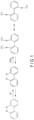
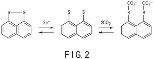
- FIGS. 1 to 3 show examples of carbon dioxide adsorption/desorption schemes by molecules having disulfide bonds.
- the disulfide bond undergoes S-S cleavage when a reduction potential is applied and is bonded to CO 2 at a negatively charged S moiety.
- an oxidation potential is applied, the bond between S and CO 2 is relieved, and a disulfide bond is formed again.
- the above chemical reaction proceeds reversibly.
- the molecule becomes disintegrated after application of a reduction potential, as illustrated.
- the disulfide bond becomes cleaved during the reduction reaction, becoming independent thiolate ions.
- the scaffold of the disulfide is not rigid, the thiolates are separated from each other by molecular motion after cleavage of the disulfide bond.
- the Red-Ox active moiety having a disulfide bond desirably includes a structure in which sulfide groups are directly bonded to a benzene ring, a naphthalene ring, or a heterocyclic ring.
- a cyclic disulfide structure directly bonded to such a rigid structure is advantageous from the viewpoint of reaction energy.
- the disulfide forms a ring structure through sharing a part of the benzene ring or the naphthalene ring.
- the cyclic disulfide structure preferably has a cyclic structure of a 4-membered ring or more and a 6-membered ring or less from the viewpoint of maintaining the open-ring and closed-ring structures relatively stable and capable of electrical conduction.
- the molecule containing a cyclic disulfide structure may have a halogen group, an amino group, a nitro group, an imide group, an imine bond, or a ketone group in addition to the disulfide.
- FIG. 4 illustrates some examples.
- FIG. 4 is a list diagram showing structural formulae of some examples of cyclic disulfide redox molecules.
- the first row in FIG. 4 shows molecules containing a cyclic disulfide structure in which a disulfide is bonded to one benzene ring to form a 4-membered ring or a 6-membered ring sharing a part thereof with the benzene ring.
- R in the structural formula represents a substituent such as the halogen group or the amino group described above, for example.
- the second row shows molecules containing a cyclic disulfide structure in which a disulfide is directly bonded to a naphthalene ring to form a 4-membered ring sharing a part thereof with one aromatic ring of the naphthalene ring.
- the left side and the center of the third row show molecules containing a cyclic disulfide structure in which a disulfide is bonded so as to form a ring by connecting two phenyl groups contained in a biphenyl, to thereby form a 6-membered ring sharing a part thereof with the biphenyl.
- the left side and the center of the fourth row show molecules containing a cyclic disulfide structure in which similar bonding are made at two positions to form two 6-membered rings sharing a part thereof with the biphenyl.
- the right sides of the third and fourth rows show molecules containing a cyclic disulfide structure in which a disulfide is directly bonded to a naphthalene ring to form a 5-membered ring sharing a part thereof with both aromatic rings of the naphthalene ring.
- the fifth row shows a molecule containing a cyclic disulfide structure in which three disulfides are directly bonded to one benzene ring to form three 4-membered rings each of which shares a part thereof with the benzene ring.
- the cyclic disulfide molecule capable of functioning as an adsorbent or the cyclic disulfide structure that can be contained in the adsorbent as a Red-Ox active moiety is not limited to the structures of the illustrated molecule.
- the Red-Ox active moiety contained in the adsorbent can be reduced in preference over oxygen to adsorb CO 2 even in the presence of oxygen. Since not only competition with the oxidation-reduction reaction of oxygen but also deterioration of the adsorbent due to active oxygen species can be avoided, it is possible to select the application environment of the adsorbent and the gas to be treated without regard for the presence or absence of oxygen.
- a material that has high binding energy to CO 2 and is lower than oxygen in the highest occupied molecular orbital (HOMO) of a molecule in a reduction state can be preferentially reduced to adsorb CO 2 in the presence of oxygen. Therefore, it is possible to estimate a molecule advantageous as a Red-Ox active moiety in the presence of oxygen by performing first principles calculation to evaluate two evaluation parameters: priority over active oxygen species generation, and CO 2 binding energy.
- the disulfide (-S-S-) compound is cleaved by twoelectron reduction to produce two thiolate ions (-S-), and CO 2 is bonded to each of the thiolate ions to form two -S-CO 2 - .
- the oxygen molecule O 2 undergoes one electron reduction, the molecule becomes an active oxygen species O 2 - (superoxide). Therefore, the difference between the stabilization energy upon generation of two molecules of O 2 - from two molecules of O 2 and the stabilization energy upon generation of two molecules of -S-CO 2 - from -S-S- is used as the priority parameter relative to active oxygen species generation.
- the stabilization energy due to bond formation with two CO 2 in a state in which -S-S- is reduced to -2 valence is taken as the CO 2 bond energy which is the other parameter.
- An example is shown below.
- the structures and energies of various oxidation-reduction responsive molecules and the interaction/adsorption reaction system between the molecules and CO 2 were calculated by density functional theory (DFT) using B3LYP functional.
- DFT density functional theory
- 6 -31 + + G (d, p) was used.
- structure optimization calculation was performed using an energy gradient method in a dielectric field of acetonitrile, and the structure obtained by reference vibration analysis was confirmed to be the equilibrium structure.
- a dielectric model polarized continuous body (PCM) model
- PCM polarized continuous body
- a small CO 2 binding energy indicates a state equivalent to the CO 2 drifting around the molecule. Therefore, the larger the energy, the more stably the bond between the molecule and CO 2 can be maintained.
- the smaller the priority parameter the difference between the achievement of the reduction state by the molecule and the generation of active oxygen species becomes more ambiguous. Therefore, the energy difference is preferably larger.
- Table 1 shows the calculation results of examples of disulfide molecules containing one cyclic disulfide structure.
- D isulfide molecules containing one cyclic disulfide structure Chemical structure R Binding energy to CO 2 (kJ/mol) Priority over active oxygen - 12.53 27.96 F 7.04 32.38 NH 2 12.46 28.22 F 9.47 30.13 NH 2 17.14 29.88 - 22.04 15.20 - 12.01 26.26 Cl 10.28 15.84 NH 2 11.27 18.10 Cl 7.46 25.4 NH 2 12.08 24.90 - 10.42 9.58 Cl 6.32 11.48 NH 2 11.95 7.44 - 79.66 57.85
- Table 2 shows the calculation results of examples of disulfide molecules containing two cyclic disulfide structures.
- D isulfide molecules containing two cyclic disulfide structures
- Chemical structure R Binding energy to CO 2 (kJ/mol) Priority over active oxygen - 40.52 2.98 - 29.73 15.95 Cl 23.04 20.97 NH 2 31.69 11.30
- FIG. 5 is a distribution diagram in which the priority over the generation of active oxygen species is plotted on the horizontal axis and the binding energy between the molecule and CO 2 is plotted on the vertical axis.
- the adsorbent may be a porous material containing a cyclic disulfide structure as a Red-Ox active moiety.
- the adsorbent may be a polymer containing a molecule including a cyclic disulfide structure as a unit structure.
- the porous material which is one of the possible forms of the carbon dioxide adsorbent, includes a porous material having a large number of pores.
- the pore diameter of the pores is preferably 5 nm or less.
- the porous material is preferably formed of a sub-nanoporous material or a nanoporous material having pores of an angstrom size (1 nm or less) to a nanometer size, and more specifically, 0.5 nm or more and 5 nm or less.
- the porous material includes a Red-Ox active moiety that is reduced by an electrical response to cleave a disulfide bond and bond with carbon dioxide and is oxidized by an electrical response to resolve the bond with carbon dioxide and re-form a disulfide bond, that is, the above-described cyclic disulfide structure.
- the Red-Ox active moiety may be contained as a functional group in the molecular structure constituting the porous material.
- the Red-Ox active moiety is not limited to the molecules and compounds described above as examples, and derivatives thereof and other molecules and compounds having a cyclic disulfide structure can also be used.
- the content of the cyclic disulfide molecule exhibiting redox activity according to electrical response contained in the porous material is preferably 10 mass% or more to 80 mass% or less, and more preferably 20 mass% or more to 75 mass% or less, with respect to the total mass of the porous material.
- the content of the cyclic disulfide-based molecule exhibiting redox activity due to electrical response is preferably 90 mass% or less with respect to the total mass of the porous material. With this content, the amount of the Red-Ox active moiety per unit volume of the porous material can be made appropriate, so that the Red-Ox active groups are not excessively close to each other, and pores can be maintained. In addition, since carbon dioxide can easily access the active group, the active group can be sufficiently utilized.
- the content of the cyclic disulfide-based molecule is more preferably 75 mass% or less.
- the porous material in which the content of the Red-Ox active moiety is within the above range is advantageous for use in carbon dioxide recovery in that, since the porous material has not only a large carbon dioxide adsorption amount and a high carbon dioxide adsorption rate, but also has a large carbon dioxide desorption amount and a high carbon dioxide desorption rate (reaction rate), whereby recovery of carbon dioxide can be performed efficiently.
- cyclic disulfide molecule capable of functioning as the Red-Ox active moiety in the porous material include molecules having an amino group or a carboxyl group as the functional group R among the molecules illustrated in FIG. 4 .
- Molecules having an amino group or a carboxyl group as the functional group R present at symmetrical positions of the ring as illustrated can be suitably incorporated into the molecular structure of the porous material.
- the cyclic disulfide molecules as active reaction points in the porous material are preferably chemically highly stable because the molecules are regenerated by desorbing CO 2 after adsorbing CO 2 and repeatedly used.
- the porous material preferably contains one or more porous substances selected from the group consisting of a covalent-organic framework (COF) having electroactivity, a metal-organic framework (MOF), a porous carbon material, zeolite, porous silica, and porous alumina.
- COF covalent-organic framework
- MOF metal-organic framework
- the porous material may include a COF having electrical responsiveness.
- the porous material may contain an MOF having electrical responsiveness.
- the presence or absence of the cyclic disulfide structure can be estimated based on Raman spectroscopy. When strong light emission derived from stretching vibration of the S-S bond is observed at 430 cm -1 to 550 cm -1 , it can be determined that disulfide is contained.
- the carbon dioxide adsorbent described above contains one or more cyclic disulfide structures.
- the adsorbent can efficiently adsorb and desorb carbon dioxide even in the presence of oxygen.
- the carbon dioxide adsorption-desorption device includes the carbon dioxide adsorbent according to the above-described approach.
- the adsorbent can exhibit redox activity by electrical response. Therefore, the carbon dioxide adsorption-desorption device can adsorb and desorb carbon dioxide to and from the Red-Ox active moiety (disulfide structure) of the adsorbent by a change in potential applied to the device.
- Such a device using the adsorbent that adsorbs and desorbs carbon dioxide with the electrically responsive Red-Ox active moiety can adsorb and desorb carbon dioxide at room temperature. Therefore, the device can adsorb and desorb carbon dioxide with low energy.
- Such a device can suitably adsorb carbon dioxide as described above and can be suitably applied to an apparatus for recovering carbon dioxide from factory exhaust gases or the atmosphere.
- a carbon dioxide recovery system can be constructed using the carbon dioxide adsorption-desorption device.
- Such a device may include an electrode for applying a charge to the Red-Ox active moiety of the disulfide adsorbent.
- the adsorbent may be included in the electrode (working electrode).
- the electrode preferably has a porous form such as a mesh shape so that more adsorbent can exchange electrons.
- the adsorbent can also be dispersed inside the porous electrode.
- the adsorbent may be dispersed in a solution within the device.
- the solution containing the adsorbent and the electrode may be arranged such that the solution and the electrode are in electrical contact with each other in the device.
- the electrode may further include a current collector.
- the adsorbent may be supported on the current collector and included in the electrode in the form of the porous material described above, in a state of being dispersed in another porous structure, or in a state of modifying an electrically conductive member.
- the porous material may be formed onto the surface of the current collector.
- the current collector can function as a conductor for transferring charge to the adsorbent to cause the Red-Ox active moiety to electrically respond.
- the Red-Ox active moiety included in the adsorbent can be oxidized and reduced, and carbon dioxide can be adsorbed to and desorbed from the moiety.
- the porous material and the electro-conductive member can be made into a composite so as to yield a porous composite.
- the composite can be obtained, for example, by mixing the porous material and the electro-conductive member or modifying (covering) the surface of the electro-conductive member with the porous material.
- the Red-Ox active moiety contained in the adsorbent is preferably close to or in contact with a nearby electro-conductive member. Therefore, it is preferable that the adsorbent covers at least a part of the surface of the electro-conductive member, or that the adsorbent is attached to the electro-conductive member.
- the above-described COF or MOF may be contained in the porous composite in a manner of covering the electro-conductive member.
- the electrode may further include a binder.
- the binder may be included, or not.
- the binder can bind the current collector, the porous material, and the electro-conductive member, or bind the current collector and the porous composite, for example.
- As the binder for example, polyvinylidene fluoride (PVdF), polymethyl methacrylate (PMMA), or polyimide (PI) may be used.
- the carbon dioxide adsorption-desorption device may further include an electrolyte (for example, an electrolytic solution).
- the adsorbent may be dispersed in the electrolyte solution.
- the electrolyte may be held in the porous material by the electrode including the porous material or the porous composite.
- the electrolyte may be contained in pores of the porous material, for example.
- an electrode containing the adsorbent or an electrode in electrical contact with a solution in which the adsorbent is dispersed is used as a working electrode.
- a potential By applying a potential to the working electrode, a charge is applied to the Red-Ox active moiety included in the adsorbent.
- the redox state of the adsorbent is switched between the oxidation state and the reduction state.
- the adsorbent can adsorb carbon dioxide in the reduction state and can desorb carbon dioxide in the oxidation state.
- the potential can be applied to the working electrode by using a counter electrode to the working electrode and applying a voltage between these electrodes.
- the carbon dioxide adsorption-desorption device may include a counter electrode to the electrode included in the device. Namely, as the carbon dioxide adsorption-desorption device, an electrochemical cell using the above working electrode and counter electrode may be configured. Aspects of the device are not limited to electrochemical cells.
- a specific example of the electrochemical cell is a three-electrode cell further including a reference electrode in addition to the working electrode and the counter electrode.
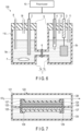
- FIG. 6 is a schematic cross-sectional view of an example of a carbon dioxide adsorption-desorption device according to the approach.
- FIG. 7 is a schematic cross-sectional view of an electrochemical cell that another example of the device may include.
- a carbon dioxide adsorption-desorption device 100 illustrated in FIG. 6 includes an electrochemical cell 110 and a potentiostat 10.
- the electrochemical cell 110 includes an electrolytic cell 1 including cells 1a and 1b, a working electrode 2, a counter electrode 3, a reference electrode 4, a separator 6, a gas introduction nozzle 8, a gas-flushing inlet 11, a gas-flushing outlet 12, a nozzle 18 for recovering desorbed carbon dioxide, and lids 9.
- the cell 1a contains an electrolytic solution 5a and a stirrer 7 that stirs the electrolytic solution 5a.
- the carbon dioxide adsorbent may be contained in the electrochemical cell 110 in a state of being dispersed in the electrolytic solution 5a.
- the cell 1b contains an electrolytic solution 5b and a stirrer 7 that stirs the electrolytic solution 5b.
- the electrolytic solution 5b does not contain the carbon dioxide adsorbent.
- the lid 9 for preventing intrusion of outside air into the cells 1a and 1b is provided on the opening of each cell, and a gas containing carbon dioxide can be introduced into the electrolytic solution 5a through the nozzle 8 penetrating the lid 9.
- the lid 9 of the cell 1a is provided with the nozzle 18 for recovering desorbed carbon dioxide.
- the lid 9 of the cell 1b is provided with the gas-flushing inlet 11 for introducing an inert gas such as nitrogen (N 2 ) and the gas-flushing outlet 12 for exhausting oxygen (O 2 ) and other gases that may have been remaining in the electrolytic solutions 5a and 5b, which can be bubbled out by a flushing procedure prior to introducing the gas containing CO 2 .
- N 2 can be introduced into the electrolytic solution 5b in the cell 1b through the gas-flushing inlet 11 with the bottom end thereof submerged into the electrolytic solution 5b, as illustrated, whereby bubbling can be performed.
- O 2 and other gases remaining in the electrolytic solutions 5a and 5b can be expelled by the bubbling, and exhausted out from the cells 1a and 1b respectively through the nozzle 18 and gas-flushing outlet 12.
- the gas-flushing inlet 11 can be drawn out from the electrolytic solution 5b (not illustrated).
- N 2 can be continually introduced into the cell 1b through the gas-flushing inlet 11 and exhausted out through the gas-flushing outlet 12 to provide a N 2 flow, so as to prevent external oxygen from entering the system during the CO 2 absorption-desorption operation.
- the potential of the working electrode 2 can be adjusted to a potential where CO 2 adsorbs to the carbon dioxide adsorbent in the electrolytic solution 5a, while the gas containing CO 2 is introduced through the nozzle 8, whereby the contained CO 2 can adsorb to the carbon dioxide adsorbent.
- the remaining gas in the cell 1a after CO 2 has been recovered therefrom can then be exhausted through the nozzle 18.
- the potential of the working electrode 2 can then be switched to a potential where CO 2 desorbs from the carbon dioxide adsorbent, and the CO 2 can be recovered from the nozzle 18.
- Valves for opening and closing the flow paths of the nozzle 8, gas-flushing inlet 11, gas-flushing outlet 12 and nozzle 18 are provided, although not shown in drawing.
- the working electrode 2 and the counter electrode 3 are separately located in the cell 1a and the cell 1b, respectively.
- the arrangement of the electrodes is not limited to this example, and for example, the counter electrode and the working electrode may be integrated with the separator interposed therebetween.
- a specific example is an electrochemical cell 120 illustrated in FIG. 7 .
- the electrochemical cell 120 illustrated in FIG. 7 includes a cell 121, a working electrode 122, a counter electrode 123, and a separator 126.
- the cell 121 is divided into upper and lower two chambers with the separator 126 interposed therebetween, and the working electrode 122 and the counter electrode 123 are provided on the upper and lower principal surfaces of the separator 126, respectively.
- An electrolytic solution 125 is contained in the lower chamber of the cell 121, and the counter electrode 123 is in contact with the electrolytic solution 125.
- the counter electrode 123 may be immersed in the electrolytic solution 125.
- the working electrode 122 is located in the upper chamber of the cell 121.
- the working electrode 122 includes a carbon dioxide adsorbent, and may include the porous composite described above, for example.
- the electrolytic solution 125 contained in the lower chamber does not include an adsorbent.
- the upper chamber in which the working electrode 122 is present can function as a gas flow path 128, and a gas containing carbon dioxide is passed through the gas flow path 128 so that the contained carbon dioxide can be adsorbed onto the adsorbent in the working electrode 122.
- a porous collector electrode 124 may be stacked on the outer side of the working electrode 122 in order to improve power distribution to the working electrode 122, and a porous support 127 for fixing the whole of the working electrode 122 and the porous collector electrode 124 may be stacked on the further outer side thereof.
- the support 127 made of a porous material may be stacked on the outside of the counter electrode 123, as well.
- the end portion of the thus fabricated stack of the porous collector electrode 124, the working electrode 122, the separator 126, and the counter electrode 123 sandwiched between the supports 127 can be fixed by fixtures 129. Since the working electrode 122 is porous, the porous collector electrode 124 may be omitted as necessary.
- the porous support 127 can be omitted.
- the electrochemical cell 120 may also be provided with an inlet and outlet used for bubbling out remaining gas from the electrolytic solution 125 and providing a N 2 flow, as well.
- a member made of carbon or metal may be used as the current collector. With the current collector having better electrical conductivity and a larger surface area, charges can be transferred to more Red-Ox active moieties.
- Examples of carbon-made members include glassy carbon, a graphite sheet, carbon felt, carbon cloth, a carbon mesh, carbon paper, and a carbon sheet with a gas diffusion layer.
- Examples of the metal member include a copper plate, a copper sheet, a copper mesh, an aluminum plate, an aluminum sheet, an aluminum mesh, a nickel plate, a nickel sheet, and a nickel mesh. The carbon members and metal members are not limited to the above.
- the electro-conductive member for example, a carbon material having good electrical conductivity can be used.
- the electro-conductive member include one or more selected from the group consisting of carbon nanotube, graphite, graphene, carbon nanofiber, and Ketjen black.
- the shape of the electro-conductive member is preferably linear or flat in order to increase the contact probability, and is preferably a rod shape, a tubular shape, a fiber shape, a sheet shape, or a flake shape.
- the electrolyte may be a liquid electrolyte (electrolytic solution), for example.
- the electrolyte includes an ionically bonded salt, for example.
- the ionically bonded salt is preferably one or more selected from the group consisting of an alkali metal salt, an alkaline earth metal salt, a transition metal salt, an amphoteric metal salt, an ammonium salt, an imidazolium salt, a pyridinium salt, and a phosphonium salt.
- the form of the ionic-bonding salt may be a solid or a liquid, and examples of the liquid include an ionic liquid.
- alkali metals such as Li, Na, K, Rb, and Cs
- alkaline earth metals such as Mg, Ca, Sr, and Ba
- transition metals such as Ti, Cr, Mn, Fe, Co, Ni, Cu, Zn, Zr, Pd, and Ag
- amphoteric metals such as Al, Ga, and Sn
- the anion of the ionic-bonding salt one or more selected from the group consisting of halogens such as Cl - , Br-, and I-, nitrate ion (NO 3 - ), PF 6 - , BF 4 - , CF 3 SO 3 - , N(SO 2 F 2 ) 2 - , N(SO 2 CF 3 ) 2 - , CH 3 COO - , CF 3 COO - , and ClO 4 - may be used, and one of the above may be used alone, or plural of the above may be used in combination.
- ion conductive polymer for example, one or more selected from the group consisting of polyethylene oxide (PEO), polypropyl oxide (PPO), polyacrylonitrile (PAN), polyvinyl chloride (PVC), an ionic liquid polymer, polyaniline, and polythiophene (PEDOT) are preferably used.
- PEO polyethylene oxide
- PPO polypropyl oxide
- PAN polyacrylonitrile
- PVC polyvinyl chloride
- an ionic liquid polymer polyaniline
- PEDOT polythiophene
- the electrolytic solution may contain a solvent.
- the solvent of the electrolytic solution may be water or an organic solvent, for example. If the electrolyte is an ionic liquid, a solvent may be used or omitted.
- the organic solvent it is desirable to use one or more selected from the group consisting of acetonitrile, propylene carbonate, ethylene carbonate, vinylene carbonate, vinylethylene carbonate, dimethyl carbonate, diethyl carbonate, ethyl methyl carbonate, succinic anhydride, cyclohexylbenzene, thiophene, toluene, fluorobenzene, and hexafluorobenzene.
- the carbon dioxide adsorption-desorption device can be manufactured as follows, for example.
- a carbon dioxide adsorbent is prepared.
- an adsorbent is obtained by synthesis.
- the prepared adsorbent can be added to the electrolytic solution, and the electrode can be set so as to be in contact with the obtained solution.
- a porous material containing the adsorbent is synthesized, and a paste containing the obtained porous material is applied onto the current collector to obtain an electrode containing the adsorbent.
- the synthesized porous material is mixed as appropriate with an electro-conductive member, a binder, a solvent, and the like to prepare the paste. This paste is applied onto the current collector to obtain an electrode.
- the paste need not necessarily contain a binder.
- the paste may be made into a free-standing electrode by heating and drying. Namely, an electrode including a porous material containing an adsorbent alone may be obtained, for example, without using the current collector.
- an electrolyte solution is prepared, the prepared solution is cast onto the electrode surface, and then vacuum impregnation is performed, whereby the electrolyte can be included within the electrode.
- the carbon dioxide adsorption-desorption device described above includes a carbon dioxide adsorbent containing one or more cyclic disulfide structures. Such a device is a carbon dioxide adsorption-desorption device capable of efficiently adsorbing and desorbing carbon dioxide with low energy.
- a carbon dioxide separation method includes, by using the carbon dioxide adsorption-desorption device described above, removing carbon dioxide from a gas containing the carbon dioxide by adsorbing the carbon dioxide onto an adsorbent, and regenerating the adsorbent by desorbing the carbon dioxide from the adsorbent.
- Adsorbing the carbon dioxide onto the adsorbent includes causing an electrical current to flow through the adsorbent at the reduction potential of the adsorbent, and bringing the gas containing the carbon dioxide into contact with the adsorbent in a state where a potential flowing through the adsorbent is maintained at the reduction potential.
- Regenerating the adsorbent by desorbing the carbon dioxide from the adsorbent includes switching the potential flowing through the adsorbent that had adsorbed carbon dioxide to the oxidation potential of the adsorbent.
- the regenerated adsorbent can be reused.
- the device By setting the device again to the reduction potential after the separation of the carbon dioxide from the adsorbent, the device is again able to perform the adsorption treatment of carbon dioxide. In this way, the device can be repeatedly used numerous times by performing switching of the potential of electrical current flowing through the adsorbent between the reduction potential and the oxidation potential.
- the method for bringing the gas containing carbon dioxide into contact with the adsorbent is not particularly limited.
- a carbon dioxide adsorption-desorption device including an electrolytic solution there is a method by which a gas containing carbon dioxide is bubbled in the electrolytic solution to cause the carbon dioxide to be adsorbed in the electrolytic solution.
- the carbon dioxide adsorption-desorption device is configured to expose the adsorbent to a gas flow containing carbon dioxide.
- the concentration of the carbon dioxide to be brought into contact with the adsorbent is not particularly limited, but may correspond to a wide range of CO 2 concentrations from an atmospheric level to a level of exhausts from a thermal power plant or the like. Specifically, the concentration of the carbon dioxide is preferably 0.01 vol% or more, and more preferably 0.04 vol% or more to 50 vol% or less.
- the environmental temperature at the time of the carbon dioxide adsorption and desorption treatment is usually preferably 0°C or more to 60°C or less.
- the temperature is more preferably 50°C or lower, and particularly preferably 10°C or more to 45°C or less.
- the adsorption amount of carbon dioxide increases at a lower temperature.
- the lower limit value of the treatment temperature can be determined by the gas temperature in the process, the heat recovery target, and the like.
- the adsorption pressure of carbon dioxide is usually approximately equal to the atmospheric pressure. Higher pressure may also be applied in order to increase adsorption performance.
- the method for adsorbing and desorbing carbon dioxide using the carbon dioxide adsorption-desorption device may include, for example, the following steps of:
- the carbon dioxide separation method described above includes causing carbon dioxide to be adsorbed onto the adsorbent included in the carbon dioxide adsorption-desorption device, causing the adsorbent that had adsorbed the carbon dioxide to desorb and separate the carbon dioxide, and regenerating the adsorbent.
- the carbon dioxide is caused to be adsorbed onto the adsorbent in a state where the electrical current flowing through the adsorbent is maintained at the reduction potential. In a state where the electrical current flowing through the adsorbent is switched to the oxidation potential then the oxidation potential is maintained, the carbon dioxide is desorbed. According to this separation method, carbon dioxide can be efficiently adsorbed and desorbed with low energy.
- a,a'-dibromo-o-xylene and urea were reacted with an ethanol solvent to obtain a crude crystal of o-xylene-a,a'-dithiol as an intermediate product. Thereafter, the intermediate product was reacted in acetone using potassium permanganate/copper sulfate pentahydrate as a catalyst to obtain 1,4-dihydrobenzo-2,3-dithiane (DHBT).
- DHBT 1,4-dihydrobenzo-2,3-dithiane
- the DHBT obtained above and tetrabutylammonium tetrafluoroborate (TBABF 4 ) as an electrolyte were added to propylene carbonate (PC) by 0.2 mol/L and 0.75 mol/L, respectively, and heated and mixed (about 80°C) to obtain a pale-yellow transparent solution.
- the obtained solution was set as an electrolytic solution in an electrolytic cell to obtain a device of Example 1. Other details of the device will be described below.
- the DBDT obtained above and TBABF 4 were added to PC, and adjusted so as to be 0.2 mol/L and 0.75 mol/L, respectively, to obtain an electrolytic solution.
- the obtained electrolytic solution was set in an electrolytic cell to obtain a device of Example 2. Other details of the device will be described below.
- the obtained azobenzene intermediate was reacted with tetrafluoroboric acid at - 30°C in diethyl ether and rearranged to 4,4'-diaminobenzodiine, and then reacted with sodium in ammonia to obtain dibenzo[c,e] [1,2]dithiine-3,8-diamine (2NH 2 -DBDT).
- the 2NH 2 -DBDT obtained above and TBABF 4 were added to PC, and adjusted so as to be 0.2 mol/L and 0.75 mol/L, respectively, to obtain an electrolytic solution.
- the obtained electrolytic solution was set in an electrolytic cell to obtain a device of Example 3. Other details of the device will be described below.
- the obtained 2NH 2 -DBDT-TFP-COF was mixed with carbon nanofibers (CNF) and polyvinylidene fluoride (PVdF) at a mass ratio of 6:3:1 under an N-methylformaldehyde solvent (NMF solvent), and applied onto a carbon felt to obtain an electrode as a composite containing a porous material.
- CNF carbon nanofibers
- PVdF polyvinylidene fluoride
- the composite electrode obtained above was set in an electrolytic cell, and a device of Example 4 was obtained using an electrolytic solution prepared by dissolving TBABF 4 in PC at 0.75 mol/L. Other details of the device will be described below.
- the NDT obtained above and TBABF 4 were added to PC, and adjusted so as to be 0.2 mol/L and 0.75 mol/L, respectively, to obtain an electrolytic solution.
- the obtained electrolytic solution was set in an electrolytic cell to obtain a device of Example 5.
- dimethylthiocarbamoyl chloride was added to [1,1'-biphenyl]-2,2,6,6'-tetraol and refluxed under a NaH catalyst in DMF.
- the obtained carbamoyl intermediate was reacted in THF with methanol having KOH dissolved therein, and the precipitate was filtered and washed with water.
- the BDBT obtained above and TBABF 4 were added to PC, and adjusted so as to be 0.2 mol/L and 0.75 mol/L, respectively, to obtain an electrolytic solution.
- the obtained electrolytic solution was set in an electrolytic cell to obtain a device of Example 6.
- DPDS diphenyl disulfide
- a device of Comparative Example 1 was obtained in the same manner as in Example 1 except that DPDS was used instead of DHBT.
- TX thioxanthone
- a device of Comparative Example 2 was obtained in the same manner as in Example 1 except that TX was used instead of DHBT.
- the DBDT prepared in Example 2 was subjected to a Raman spectroscopy measurement.
- the Raman spectroscopy measurement was performed as follows.
- the DBDT was subjected to Raman spectrometry using a Raman spectrometer (LabRAM Evolution manufactured by HORIBA) in a measurement range of 200 cm -1 to 3300 cm -1 at an excitation laser wavelength of 532 nm.
- a Raman spectrometer (LabRAM Evolution manufactured by HORIBA) in a measurement range of 200 cm -1 to 3300 cm -1 at an excitation laser wavelength of 532 nm.
- the DBDT prepared in Example 2 was subjected to 1 H and 13 C NMR measurements.
- the measurement conditions and the peaks observed in the measurement spectrum were as follows.
- Each of the devices produced in Examples 1 to 6 and Comparative Examples 1 and 2 was evaluated for electrochemical performance. Specifically, a test device using each of the produced devices was constructed and subjected to cyclic voltammetry (CV) measurement.
- CV cyclic voltammetry
- Example 1 to 3 a three-electrode electrochemical cell configuration identical to that of the carbon dioxide adsorption-desorption device 100 illustrated in FIG. 6 was adopted for the test device.
- a working electrode 2 an electrolytic solution containing the adsorbent prepared in each of Examples 1 to 3, 5 and 6 and Comparative Examples 1 and 2 was used as a working electrode-side electrolytic solution (5a)
- a platinum mesh electrode was used as the counter electrode 3
- a 0.01 mol/L TBABF 4 electrolytic solution containing 0.75 mol/L ferrocene was used as a counter electrode-side electrolytic solution (5b)
- an Ag/Ag + electrode acetonitrile/0.1 M (M: mol/L) tetrabutylammonium perchlorate solution/0.01 M AgNO 3 ) was used as a reference electrode 4.
- argon (Ar) gas was passed through a nozzle 8 into the electrolytic solution 5a within a cell 1a for about 30 minutes, and CV measurement was performed using a potentiostat 10. Subsequently, 100% carbon dioxide gas was passed through the nozzle 8 into an electrolytic solution 5a for about 30 minutes, and CV measurement was performed again.
- Example 4 since the adsorbent was integrated with the electrode, measurement was performed with a test device using an electrochemical cell having the configuration shown in FIG. 7 .
- the prepared composite electrode was used as a working electrode 122, and was stacked on a platinum mesh electrode as a counter electrode 123 with a separator 126 interposed therebetween.
- a porous collector electrode 124 was stacked on the outside of the working electrode 122, and a porous support 127 for fixing the entire electrode was stacked further on the outer side thereof.
- a support 127 made of a porous material was stacked on the outside of the counter electrode 123, and the ends were fixed by fixtures 129.
- An electrolytic solution 125 (0.01 mol/L TBABF 4 solution containing 0.75 mol/L ferrocene without adsorbent) was put into one chamber of a cell 121 having two communicating chambers, and the stack including the working electrode 122 and the counter electrode 123 was set in the cell 121 so as to block the communication between the two chambers and to immerse the counter electrode 123 in the electrolytic solution 125.
- the chamber into which the electrolytic solution 125 was not put was used as a gas flow path 128 through which Ar gas and carbon dioxide gas were allowed to pass.
- the separator 126 used had a structure in which the electrolytic solution 125 permeates into the working electrode 122 through the separator 126. CV measurement was performed in the same manner as in Example 1 and the like except that such an electrochemical cell 120 was used.
- FIG. 8 shows the CV measurement results of DBDT obtained by the device of Example 1.
- a curve during the first CV measurement under an Ar atmosphere is indicated by a broken line
- a curve during the second CV measurement under a CO 2 atmosphere is indicated by a solid line.
- a reduction peak associated with S-S bond cleavage around -1.9 V vs. Ag/Ag +
- oxidation peaks associated with S-S recombination around -0.66 V and -0.12 V vs. Ag/Ag +
- a current value decreased at -0.66 V (vs.
- a carbon dioxide adsorption and desorption test was performed using the devices produced in each of Example 1 to 6 and Comparative Examples 1 and 2.
- the basic operations of the test are the same as the CV evaluation.
- an inert gas was introduced into the electrolytic solution, and bubbling was carried out for about 30 minutes.
- argon gas was used as the inert gas.
- carbon dioxide gas a potential slightly exceeding the reduction potential of each adsorbent was applied for a set period of time to adsorb carbon dioxide onto the adsorbent.
- the space above the electrolytic solution was replaced with an inert gas, and a tube for recovering CO 2 was connected to the cell.
- the carbon dioxide was desorbed from the adsorbent by applying a potential slightly exceeding the oxidation potential of each adsorbent for a set period of time in a state where all portions except the CO 2 recovery tube were sealed.
- the desorbed carbon dioxide accumulated in the space above the electrolytic solution.
- sampling was performed on the space above the electrolytic solution.
- the collected gas was used to perform quantification by gas chromatography/mass spectrometry (GC/MS), and the amount of carbon dioxide adsorbed and recovered by the adsorbent was determined.
- Table 3 shows the amount of CO 2 recovered by each adsorbent. Table 3 also shows the abbreviation and chemical structure of each adsorbent.
- Example 4 is shown below Table 3 due to its large size.
- Table 3 Amounts of CO 2 Recovered in Examples and Comparative Examples
- Example 1 DHBT 1.6
- Example 3 2NH 2 -DBDT 2.3
- Example 4 2NH 2 -DBDT-TFP-COF (Shown outside Table 3)
- Example 5 3.3
- Example 2 and Comparative Example 1 in Table 3 it can be advantageous that the disulfide bond is cyclic. It can be seen from Example 2 and 3 that for adsorbents having a cyclic disulfide structure, large differences do not arise due to the substituent. It can further be seen from Examples 3 and 4 that since COF was present on the electrode, the exchange of electrons was easier than that of the solution type, and the amount of CO 2 was slightly increased.
- a carbon dioxide adsorbent and a carbon dioxide adsorption-desorption device using the same are provided.
- the carbon dioxide adsorbent includes one or more cyclic disulfide structures, and is able to efficiently adsorb and desorb carbon dioxide. Accordingly, the device is able to efficiently adsorb and desorb carbon dioxide, and can perform efficient recovery of carbon dioxide.
Landscapes
- Chemical & Material Sciences (AREA)
- Chemical Kinetics & Catalysis (AREA)
- Analytical Chemistry (AREA)
- Organic Chemistry (AREA)
- General Health & Medical Sciences (AREA)
- Toxicology (AREA)
- Physics & Mathematics (AREA)
- Electromagnetism (AREA)
- Health & Medical Sciences (AREA)
- Engineering & Computer Science (AREA)
- General Chemical & Material Sciences (AREA)
- Oil, Petroleum & Natural Gas (AREA)
- Inorganic Chemistry (AREA)
- Carbon And Carbon Compounds (AREA)
- Solid-Sorbent Or Filter-Aiding Compositions (AREA)
Abstract
A carbon dioxide adsorbent is provided. The carbon dioxide adsorbent is capable of adsorbing and desorbing carbon dioxide and includes one or more cyclic disulfide structures.
Description
- The present disclosure relates to a carbon dioxide adsorbent and a carbon dioxide adsorption-desorption device.
- A technique for causing carbon dioxide (CO2) to be absorbed into an absorbent such as an amine is used in a carbon dioxide capture and storage (CCS) plant such as a thermal power plant and is regarded as a most promising candidate as a technique for global warming prevention. The absorbent that has absorbed carbon dioxide is generally heated in a regeneration tower, thereby being regenerated by releasing the carbon dioxide, and repeatedly used. A general temperature for heating there is about 140°C, consuming great energy. Heat and energy required for regeneration are also called heat duty or energy penalty. If this heating temperature can be lowered to efficiently release carbon dioxide, energy reduction can be achieved, allowing promotion of the spread of this technique as a technique for global warming prevention.
- As an energy-saving regeneration method, there is a method by which adsorbed carbon dioxide is substituted with water vapor. Carbon dioxide is released from the adsorbent by a substitution reaction of adsorbed carbon dioxide with water vapor. According to this method, the heating temperature can be lowered to 100°C or lower, but water vapor is contained in the released gas in addition to carbon dioxide. Therefore, the process of cooling the released gas, condensing the water vapor, to thereby separate the water vapor from the carbon dioxide is added at a subsequent stage. Therefore, although energy saving can be achieved as compared with thermal desorption, the method can hardly be said to be optimal as a method for regenerating an absorbent.
- On the other hand, there has also been studied a technique of separating carbon dioxide by switching between electrical potentials, instead of heating, using molecules or a polymer containing electroactive groups. By using this method, carbon dioxide can be released without heating, so that the effect of energy saving can be expected. Carbon dioxide separation by potential switching can be roughly classified into two types. In the first of the two types, upon adsorption-desorption of carbon dioxide, charge is accumulated in a reaction moiety to adsorb carbon dioxide. In the other type, carbon dioxide is adsorbed in accompany of bond cleavage. In the latter type in which bond cleavage occurs, ease of recombination greatly affects the reaction efficiency.
-
-
FIG. 1 is a CO2 adsorption/desorption scheme by an example of a cyclic disulfide redox molecule. -
FIG. 2 is a CO2 adsorption/desorption scheme by another example of a cyclic disulfide redox molecule. -
FIG. 3 is a CO2 adsorption/desorption scheme by an example of an acyclic disulfide redox molecule. -
FIG. 4 is a list diagram showing structural formulae of examples of cyclic disulfide-based redox molecules. -
FIG. 5 is a distribution diagram showing the CO2 binding energy at the reaction moiety and the priority of CO2 adsorption to the reaction moiety as compared with generation of active oxygen species for some examples of oxidation-reduction molecules. -
FIG. 6 is a cross-sectional view schematically representing an example of a carbon dioxide adsorption-desorption device according to the approach. -
FIG. 7 is a cross-sectional view schematically representing an electrochemical cell that may be included in another example of a carbon dioxide adsorption-desorption device according to the approach. -
FIG. 8 is a graph representing a cyclic voltammetry curve measured in Example 2. - According to one approach, a carbon dioxide adsorbent is provided. The carbon dioxide adsorbent is capable of adsorbing and desorbing carbon dioxide and includes one or more cyclic disulfide structures.
- The above approach provides an adsorbent that can realize a carbon dioxide adsorption-desorption device capable of efficiently adsorbing and desorbing carbon dioxide, and a carbon dioxide adsorption-desorption device including the adsorbent.
- Hereinafter, approaches will be described with reference to the drawings. The same reference signs are applied to common components throughout the approaches and overlapped explanations are thereby omitted. Each drawing is a schematic view for encouraging explanations of the approach and understanding thereof, and thus there are some details in which a shape, a size and a ratio are different from those in a device actually used, but they can be appropriately design-changed considering the following explanations and known technology.
- The approaches described below relate to an adsorbent and a device for separating carbon dioxide (CO2) from a gas containing the carbon dioxide by an electrochemical process. The adsorbent is one that has been found to be capable of realizing an electrical response device that efficiently adsorbs and desorbs carbon dioxide.
- The carbon dioxide adsorbent according to the approach contains one or more cyclic disulfide structures. The carbon dioxide adsorbent can adsorb and desorb carbon dioxide by containing the cyclic disulfide structure. Hereinafter, the carbon dioxide adsorbent may be simply referred to as "adsorbent". A compound or a material containing a cyclic disulfide structure can be produced by applying a known method as appropriate.
- According to an approach, there is provided an adsorbent for a device that performs gas adsorption and desorption through an electrochemical swing (electroswing adsorption). The electrochemical swing process is a process of maintaining a specific potential in the forward direction and maintaining a different potential in the reverse direction. In this method, using Red-Ox active groups that can be put into a reduction state at a certain potential and an oxidation state at a different potential makes it possible to adjust affinity for a target adsorption substance. According to the approach, energy is efficiently delivered to act on an electrochemical reaction that results in capture of a target substance (for example, CO2).
- In such an adsorbent, the cyclic disulfide structure exhibits an oxidation-reduction response. Namely, the cyclic disulfide structure functions as a Red-Ox active moiety. In the adsorbent, carbon dioxide is adsorbed and desorbed by the oxidation-reduction response of the cyclic disulfide structure. Specifically, carbon dioxide can be adsorbed to the cyclic disulfide structure in a reduction state, and the carbon dioxide adsorbed to the cyclic disulfide structure can be desorbed in an oxidation state.
- It has been reported that a typical adsorbent responsive to oxidation-reduction competes with an oxidation-reduction reaction of oxygen depending on the use environment. In an environment where oxygen exists, active oxygen species may be generated by an oxidation-reduction reaction of oxygen, and it is known that the active oxygen species deteriorate the adsorbent. Therefore, it is desirable that the adsorbent can preferentially exchange electrons even in the presence of oxygen, that is, the adsorbent exhibits a higher oxidation-reduction potential than that of oxygen.
- As a result of intensive studies, it was found that the oxidation-reduction potential of a group of molecules having a disulfide bond tends to be higher than the oxidation-reduction potential of oxygen.
FIGS. 1 to 3 show examples of carbon dioxide adsorption/desorption schemes by molecules having disulfide bonds. The disulfide bond undergoes S-S cleavage when a reduction potential is applied and is bonded to CO2 at a negatively charged S moiety. Conversely, when an oxidation potential is applied, the bond between S and CO2 is relieved, and a disulfide bond is formed again. The above chemical reaction proceeds reversibly. - Among the group of molecules having a disulfide bond, in a case where the disulfide bond is not included in a cyclic structure as in the example shown in
FIG. 3 , the molecule becomes disintegrated after application of a reduction potential, as illustrated. In this manner, with the acyclic disulfide compound, the disulfide bond becomes cleaved during the reduction reaction, becoming independent thiolate ions. As with this example, even with a compound having a cyclic structure, if the scaffold of the disulfide is not rigid, the thiolates are separated from each other by molecular motion after cleavage of the disulfide bond. Even if an oxidation potential is applied, the disulfide structure cannot be regenerated unless the independent ions come close to each other again by chance. Therefore, more energy is required to form a disulfide bond again as compared with recombination of a rigid cyclic disulfide bond. For this reason, even with a cyclic structure, it is difficult to take advantage of the benefit of the ring with a compound that has the disulfide positioned within a linear alkyl, for example. Therefore, the re-formation of the S-S bond is regarded as a disproportionation reaction and is inefficient. - In contrast, in a group of molecules in which a disulfide bond is included in a cyclic structure as in the examples of
FIGS. 1 and2 , the same molecule is maintained even after S-S cleavage, which is advantageous at the time of S-S recombination. In such a compound having a cyclic disulfide structure in which a disulfide forms a part of the ring, the distance between two thiolate ions within the molecule is kept substantially constant even if a disulfide bond is cleaved. Therefore, with an adsorbent containing a cyclic disulfide structure, the recombination efficiency of disulfide bonds is increased, and it is possible to provide an electrically responsive carbon dioxide adsorption-desorption device that can efficiently adsorb and desorb carbon dioxide. - The Red-Ox active moiety having a disulfide bond desirably includes a structure in which sulfide groups are directly bonded to a benzene ring, a naphthalene ring, or a heterocyclic ring. For the reasons described above, inclusion of a cyclic disulfide structure directly bonded to such a rigid structure is advantageous from the viewpoint of reaction energy. Further, it is preferable that the disulfide forms a ring structure through sharing a part of the benzene ring or the naphthalene ring. The cyclic disulfide structure preferably has a cyclic structure of a 4-membered ring or more and a 6-membered ring or less from the viewpoint of maintaining the open-ring and closed-ring structures relatively stable and capable of electrical conduction. The molecule containing a cyclic disulfide structure may have a halogen group, an amino group, a nitro group, an imide group, an imine bond, or a ketone group in addition to the disulfide.
FIG. 4 illustrates some examples. -
FIG. 4 is a list diagram showing structural formulae of some examples of cyclic disulfide redox molecules. The first row inFIG. 4 shows molecules containing a cyclic disulfide structure in which a disulfide is bonded to one benzene ring to form a 4-membered ring or a 6-membered ring sharing a part thereof with the benzene ring. R in the structural formula represents a substituent such as the halogen group or the amino group described above, for example. The second row shows molecules containing a cyclic disulfide structure in which a disulfide is directly bonded to a naphthalene ring to form a 4-membered ring sharing a part thereof with one aromatic ring of the naphthalene ring. The left side and the center of the third row show molecules containing a cyclic disulfide structure in which a disulfide is bonded so as to form a ring by connecting two phenyl groups contained in a biphenyl, to thereby form a 6-membered ring sharing a part thereof with the biphenyl. The left side and the center of the fourth row show molecules containing a cyclic disulfide structure in which similar bonding are made at two positions to form two 6-membered rings sharing a part thereof with the biphenyl. The right sides of the third and fourth rows show molecules containing a cyclic disulfide structure in which a disulfide is directly bonded to a naphthalene ring to form a 5-membered ring sharing a part thereof with both aromatic rings of the naphthalene ring. The fifth row shows a molecule containing a cyclic disulfide structure in which three disulfides are directly bonded to one benzene ring to form three 4-membered rings each of which shares a part thereof with the benzene ring. The cyclic disulfide molecule capable of functioning as an adsorbent or the cyclic disulfide structure that can be contained in the adsorbent as a Red-Ox active moiety is not limited to the structures of the illustrated molecule. - It is preferable that the Red-Ox active moiety contained in the adsorbent can be reduced in preference over oxygen to adsorb CO2 even in the presence of oxygen. Since not only competition with the oxidation-reduction reaction of oxygen but also deterioration of the adsorbent due to active oxygen species can be avoided, it is possible to select the application environment of the adsorbent and the gas to be treated without regard for the presence or absence of oxygen. A material that has high binding energy to CO2 and is lower than oxygen in the highest occupied molecular orbital (HOMO) of a molecule in a reduction state can be preferentially reduced to adsorb CO2 in the presence of oxygen. Therefore, it is possible to estimate a molecule advantageous as a Red-Ox active moiety in the presence of oxygen by performing first principles calculation to evaluate two evaluation parameters: priority over active oxygen species generation, and CO2 binding energy.
- The disulfide (-S-S-) compound is cleaved by twoelectron reduction to produce two thiolate ions (-S-), and CO2 is bonded to each of the thiolate ions to form two -S-CO2 -. On the other hand, when the oxygen molecule O2 undergoes one electron reduction, the molecule becomes an active oxygen species O2 - (superoxide). Therefore, the difference between the stabilization energy upon generation of two molecules of O2 - from two molecules of O2 and the stabilization energy upon generation of two molecules of -S-CO2 - from -S-S- is used as the priority parameter relative to active oxygen species generation. In addition, the stabilization energy due to bond formation with two CO2 in a state in which -S-S- is reduced to -2 valence is taken as the CO2 bond energy which is the other parameter. An example is shown below.
- The structures and energies of various oxidation-reduction responsive molecules and the interaction/adsorption reaction system between the molecules and CO2 were calculated by density functional theory (DFT) using B3LYP functional. As a basis function system, 6 -31 + + G (d, p) was used. Regarding the molecular structure, structure optimization calculation was performed using an energy gradient method in a dielectric field of acetonitrile, and the structure obtained by reference vibration analysis was confirmed to be the equilibrium structure. For the calculation in the dielectric field, a dielectric model (polarized continuous body (PCM) model) considering a solvent effect was used. All the calculations were performed using a molecular orbital calculation program Gaussian 16 (manufactured by Hulinks Inc.).
- A small CO2 binding energy indicates a state equivalent to the CO2 drifting around the molecule. Therefore, the larger the energy, the more stably the bond between the molecule and CO2 can be maintained. The smaller the priority parameter, the difference between the achievement of the reduction state by the molecule and the generation of active oxygen species becomes more ambiguous. Therefore, the energy difference is preferably larger.
- Table 1 shows the calculation results of examples of disulfide molecules containing one cyclic disulfide structure.
[Table 1] D isulfide molecules containing one cyclic disulfide structure Chemical structure R Binding energy to CO2 (kJ/mol) Priority over active oxygen 
- 12.53 27.96 
F 7.04 32.38 NH2 12.46 28.22 
F 9.47 30.13 NH2 17.14 29.88 
- 22.04 15.20 
- 12.01 26.26 
Cl 10.28 15.84 NH2 11.27 18.10 
Cl 7.46 25.4 NH2 12.08 24.90 
- 10.42 9.58 
Cl 6.32 11.48 NH2 11.95 7.44 
- 79.66 57.85 - Similarly, Table 2 shows the calculation results of examples of disulfide molecules containing two cyclic disulfide structures.
[Table 2] D isulfide molecules containing two cyclic disulfide structures Chemical structure R Binding energy to CO2 (kJ/mol) Priority over active oxygen 
- 40.52 2.98 
- 29.73 15.95 
Cl 23.04 20.97 NH2 31.69 11.30 - Some of the results shown in Table 1 are summarized in
FIG. 5. FIG. 5 is a distribution diagram in which the priority over the generation of active oxygen species is plotted on the horizontal axis and the binding energy between the molecule and CO2 is plotted on the vertical axis. - The adsorbent may be a porous material containing a cyclic disulfide structure as a Red-Ox active moiety. The adsorbent may be a polymer containing a molecule including a cyclic disulfide structure as a unit structure.
- The porous material, which is one of the possible forms of the carbon dioxide adsorbent, includes a porous material having a large number of pores. The pore diameter of the pores is preferably 5 nm or less. Specifically, the porous material is preferably formed of a sub-nanoporous material or a nanoporous material having pores of an angstrom size (1 nm or less) to a nanometer size, and more specifically, 0.5 nm or more and 5 nm or less.
- The porous material includes a Red-Ox active moiety that is reduced by an electrical response to cleave a disulfide bond and bond with carbon dioxide and is oxidized by an electrical response to resolve the bond with carbon dioxide and re-form a disulfide bond, that is, the above-described cyclic disulfide structure. The Red-Ox active moiety may be contained as a functional group in the molecular structure constituting the porous material. The Red-Ox active moiety is not limited to the molecules and compounds described above as examples, and derivatives thereof and other molecules and compounds having a cyclic disulfide structure can also be used.
- The content of the cyclic disulfide molecule exhibiting redox activity according to electrical response contained in the porous material is preferably 10 mass% or more to 80 mass% or less, and more preferably 20 mass% or more to 75 mass% or less, with respect to the total mass of the porous material.
- In general, the larger the amount of the active groups contained in the adsorbent, the greater the adsorption amount and desorption amount of carbon dioxide per unit volume of the adsorbent. Therefore, from the viewpoint of energy consumption, the size of plant equipment, and treatment efficiency, it is desirable to have a large amount of active groups.
- The content of the cyclic disulfide-based molecule exhibiting redox activity due to electrical response is preferably 90 mass% or less with respect to the total mass of the porous material. With this content, the amount of the Red-Ox active moiety per unit volume of the porous material can be made appropriate, so that the Red-Ox active groups are not excessively close to each other, and pores can be maintained. In addition, since carbon dioxide can easily access the active group, the active group can be sufficiently utilized. The content of the cyclic disulfide-based molecule is more preferably 75 mass% or less.
- By setting the content of the Red-Ox active moiety to 10 mass% or more, sufficient adsorption amount and adsorption rate of carbon dioxide can be obtained, and excellent treatment efficiency can be obtained. Therefore, the porous material in which the content of the Red-Ox active moiety is within the above range is advantageous for use in carbon dioxide recovery in that, since the porous material has not only a large carbon dioxide adsorption amount and a high carbon dioxide adsorption rate, but also has a large carbon dioxide desorption amount and a high carbon dioxide desorption rate (reaction rate), whereby recovery of carbon dioxide can be performed efficiently.
- Specific examples of the cyclic disulfide molecule capable of functioning as the Red-Ox active moiety in the porous material include molecules having an amino group or a carboxyl group as the functional group R among the molecules illustrated in
FIG. 4 . Molecules having an amino group or a carboxyl group as the functional group R present at symmetrical positions of the ring as illustrated can be suitably incorporated into the molecular structure of the porous material. - As in the above example, the cyclic disulfide molecules as active reaction points in the porous material are preferably chemically highly stable because the molecules are regenerated by desorbing CO2 after adsorbing CO2 and repeatedly used.
- The porous material preferably contains one or more porous substances selected from the group consisting of a covalent-organic framework (COF) having electroactivity, a metal-organic framework (MOF), a porous carbon material, zeolite, porous silica, and porous alumina. For example, the porous material may include a COF having electrical responsiveness. Alternatively, the porous material may contain an MOF having electrical responsiveness.
- The presence or absence of the cyclic disulfide structure can be estimated based on Raman spectroscopy. When strong light emission derived from stretching vibration of the S-S bond is observed at 430 cm-1 to 550 cm-1, it can be determined that disulfide is contained. According to the results of the Raman spectroscopic measurement of a sample containing a cyclic disulfide structure, for example, strong light emission derived from stretching vibration of an aliphatic S-C bond at 630 cm-1 to 790 cm-1 or strong light emission derived from stretching vibration of an aromatic S-C bond at 1060 cm-1 to 1100 cm-1 can be observed, and in some cases, strong light emission derived from stretching vibration of a C-C bond at a crosslinked portion between benzene rings may be observed at 1280 cm-1 to 1300 cm-1. Based on 1H NMR (nuclear magnetic resonance) and 13C NMR measurement, a structure forming a disulfide-containing ring structure can be estimated. Raman spectrometry and NMR spectrometry are combined to examine whether the carbon dioxide adsorbent has a cyclic disulfide structure.
- The carbon dioxide adsorbent described above contains one or more cyclic disulfide structures. The adsorbent can efficiently adsorb and desorb carbon dioxide even in the presence of oxygen.
- The carbon dioxide adsorption-desorption device according to the approach includes the carbon dioxide adsorbent according to the above-described approach.
- As described above, the adsorbent can exhibit redox activity by electrical response. Therefore, the carbon dioxide adsorption-desorption device can adsorb and desorb carbon dioxide to and from the Red-Ox active moiety (disulfide structure) of the adsorbent by a change in potential applied to the device. Such a device using the adsorbent that adsorbs and desorbs carbon dioxide with the electrically responsive Red-Ox active moiety can adsorb and desorb carbon dioxide at room temperature. Therefore, the device can adsorb and desorb carbon dioxide with low energy.
- Such a device can suitably adsorb carbon dioxide as described above and can be suitably applied to an apparatus for recovering carbon dioxide from factory exhaust gases or the atmosphere. For example, a carbon dioxide recovery system can be constructed using the carbon dioxide adsorption-desorption device.
- Such a device may include an electrode for applying a charge to the Red-Ox active moiety of the disulfide adsorbent. In the device, the adsorbent may be included in the electrode (working electrode). The electrode preferably has a porous form such as a mesh shape so that more adsorbent can exchange electrons. The adsorbent can also be dispersed inside the porous electrode. The adsorbent may be dispersed in a solution within the device. The solution containing the adsorbent and the electrode may be arranged such that the solution and the electrode are in electrical contact with each other in the device.
- The electrode may further include a current collector. For example, the adsorbent may be supported on the current collector and included in the electrode in the form of the porous material described above, in a state of being dispersed in another porous structure, or in a state of modifying an electrically conductive member. For example, the porous material may be formed onto the surface of the current collector.
- The current collector can function as a conductor for transferring charge to the adsorbent to cause the Red-Ox active moiety to electrically respond. By varying the potential of the current collector, the Red-Ox active moiety included in the adsorbent can be oxidized and reduced, and carbon dioxide can be adsorbed to and desorbed from the moiety.
- The porous material and the electro-conductive member can be made into a composite so as to yield a porous composite. The composite can be obtained, for example, by mixing the porous material and the electro-conductive member or modifying (covering) the surface of the electro-conductive member with the porous material.
- In the porous composite, the Red-Ox active moiety contained in the adsorbent is preferably close to or in contact with a nearby electro-conductive member. Therefore, it is preferable that the adsorbent covers at least a part of the surface of the electro-conductive member, or that the adsorbent is attached to the electro-conductive member. For example, the above-described COF or MOF may be contained in the porous composite in a manner of covering the electro-conductive member.
- The electrode may further include a binder. The binder may be included, or not. The binder can bind the current collector, the porous material, and the electro-conductive member, or bind the current collector and the porous composite, for example. As the binder, for example, polyvinylidene fluoride (PVdF), polymethyl methacrylate (PMMA), or polyimide (PI) may be used.
- The carbon dioxide adsorption-desorption device may further include an electrolyte (for example, an electrolytic solution). The adsorbent may be dispersed in the electrolyte solution. Alternatively, the electrolyte may be held in the porous material by the electrode including the porous material or the porous composite. The electrolyte may be contained in pores of the porous material, for example. By including the electrolyte, electrical conductivity is improved, and the ability to adsorb and desorb CO2 is enhanced.
- In the device, an electrode containing the adsorbent or an electrode in electrical contact with a solution in which the adsorbent is dispersed is used as a working electrode. By applying a potential to the working electrode, a charge is applied to the Red-Ox active moiety included in the adsorbent. As such, by controlling the potential of the electrode, the redox state of the adsorbent is switched between the oxidation state and the reduction state. The adsorbent can adsorb carbon dioxide in the reduction state and can desorb carbon dioxide in the oxidation state.
- For example, the potential can be applied to the working electrode by using a counter electrode to the working electrode and applying a voltage between these electrodes. For example, the carbon dioxide adsorption-desorption device may include a counter electrode to the electrode included in the device. Namely, as the carbon dioxide adsorption-desorption device, an electrochemical cell using the above working electrode and counter electrode may be configured. Aspects of the device are not limited to electrochemical cells. A specific example of the electrochemical cell is a three-electrode cell further including a reference electrode in addition to the working electrode and the counter electrode.
- A specific example of a carbon dioxide adsorption-desorption device according to the approach will be described with reference to
FIGS. 6 and 7. FIG. 6 is a schematic cross-sectional view of an example of a carbon dioxide adsorption-desorption device according to the approach.FIG. 7 is a schematic cross-sectional view of an electrochemical cell that another example of the device may include. - A carbon dioxide adsorption-
desorption device 100 illustrated inFIG. 6 includes anelectrochemical cell 110 and apotentiostat 10. Theelectrochemical cell 110 includes anelectrolytic cell 1 includingcells electrode 2, acounter electrode 3, areference electrode 4, aseparator 6, a gas introduction nozzle 8, a gas-flushinginlet 11, a gas-flushingoutlet 12, anozzle 18 for recovering desorbed carbon dioxide, and lids 9. Thecell 1a contains anelectrolytic solution 5a and astirrer 7 that stirs theelectrolytic solution 5a. The carbon dioxide adsorbent may be contained in theelectrochemical cell 110 in a state of being dispersed in theelectrolytic solution 5a. Thecell 1b contains anelectrolytic solution 5b and astirrer 7 that stirs theelectrolytic solution 5b. In one example, theelectrolytic solution 5b does not contain the carbon dioxide adsorbent. The lid 9 for preventing intrusion of outside air into thecells electrolytic solution 5a through the nozzle 8 penetrating the lid 9. The lid 9 of thecell 1a is provided with thenozzle 18 for recovering desorbed carbon dioxide. The lid 9 of thecell 1b is provided with the gas-flushinginlet 11 for introducing an inert gas such as nitrogen (N2) and the gas-flushingoutlet 12 for exhausting oxygen (O2) and other gases that may have been remaining in theelectrolytic solutions electrolytic solution 5b in thecell 1b through the gas-flushinginlet 11 with the bottom end thereof submerged into theelectrolytic solution 5b, as illustrated, whereby bubbling can be performed. O2 and other gases remaining in theelectrolytic solutions cells nozzle 18 and gas-flushingoutlet 12. After eliminating the remaining gas by bubbling, the gas-flushinginlet 11 can be drawn out from theelectrolytic solution 5b (not illustrated). N2 can be continually introduced into thecell 1b through the gas-flushinginlet 11 and exhausted out through the gas-flushingoutlet 12 to provide a N2 flow, so as to prevent external oxygen from entering the system during the CO2 absorption-desorption operation. The potential of the workingelectrode 2 can be adjusted to a potential where CO2 adsorbs to the carbon dioxide adsorbent in theelectrolytic solution 5a, while the gas containing CO2 is introduced through the nozzle 8, whereby the contained CO2 can adsorb to the carbon dioxide adsorbent. The remaining gas in thecell 1a after CO2 has been recovered therefrom can then be exhausted through thenozzle 18. The potential of the workingelectrode 2 can then be switched to a potential where CO2 desorbs from the carbon dioxide adsorbent, and the CO2 can be recovered from thenozzle 18. Valves for opening and closing the flow paths of the nozzle 8, gas-flushinginlet 11, gas-flushingoutlet 12 andnozzle 18 are provided, although not shown in drawing. In the illustrated example, the workingelectrode 2 and thecounter electrode 3 are separately located in thecell 1a and thecell 1b, respectively. The arrangement of the electrodes is not limited to this example, and for example, the counter electrode and the working electrode may be integrated with the separator interposed therebetween. A specific example is anelectrochemical cell 120 illustrated inFIG. 7 . - The
electrochemical cell 120 illustrated inFIG. 7 includes acell 121, a workingelectrode 122, acounter electrode 123, and aseparator 126. Thecell 121 is divided into upper and lower two chambers with theseparator 126 interposed therebetween, and the workingelectrode 122 and thecounter electrode 123 are provided on the upper and lower principal surfaces of theseparator 126, respectively. Anelectrolytic solution 125 is contained in the lower chamber of thecell 121, and thecounter electrode 123 is in contact with theelectrolytic solution 125. Thecounter electrode 123 may be immersed in theelectrolytic solution 125. The workingelectrode 122 is located in the upper chamber of thecell 121. The workingelectrode 122 includes a carbon dioxide adsorbent, and may include the porous composite described above, for example. Theelectrolytic solution 125 contained in the lower chamber does not include an adsorbent. The upper chamber in which the workingelectrode 122 is present can function as agas flow path 128, and a gas containing carbon dioxide is passed through thegas flow path 128 so that the contained carbon dioxide can be adsorbed onto the adsorbent in the workingelectrode 122. - A
porous collector electrode 124 may be stacked on the outer side of the workingelectrode 122 in order to improve power distribution to the workingelectrode 122, and aporous support 127 for fixing the whole of the workingelectrode 122 and theporous collector electrode 124 may be stacked on the further outer side thereof. Similarly, thesupport 127 made of a porous material may be stacked on the outside of thecounter electrode 123, as well. The end portion of the thus fabricated stack of theporous collector electrode 124, the workingelectrode 122, theseparator 126, and thecounter electrode 123 sandwiched between thesupports 127 can be fixed byfixtures 129. Since the workingelectrode 122 is porous, theporous collector electrode 124 may be omitted as necessary. When the mechanical strengths of the workingelectrode 122 and thecounter electrode 123 are sufficient, theporous support 127 can be omitted. Although not illustrated, theelectrochemical cell 120 may also be provided with an inlet and outlet used for bubbling out remaining gas from theelectrolytic solution 125 and providing a N2 flow, as well. - Hereinafter, the current collector, the electro-conductive member, and the electrolytic solution will be described in detail.
- As the current collector, a member made of carbon or metal may be used. With the current collector having better electrical conductivity and a larger surface area, charges can be transferred to more Red-Ox active moieties. Examples of carbon-made members include glassy carbon, a graphite sheet, carbon felt, carbon cloth, a carbon mesh, carbon paper, and a carbon sheet with a gas diffusion layer. Examples of the metal member include a copper plate, a copper sheet, a copper mesh, an aluminum plate, an aluminum sheet, an aluminum mesh, a nickel plate, a nickel sheet, and a nickel mesh. The carbon members and metal members are not limited to the above.
- As the electro-conductive member, for example, a carbon material having good electrical conductivity can be used. Examples of the electro-conductive member include one or more selected from the group consisting of carbon nanotube, graphite, graphene, carbon nanofiber, and Ketjen black. The shape of the electro-conductive member is preferably linear or flat in order to increase the contact probability, and is preferably a rod shape, a tubular shape, a fiber shape, a sheet shape, or a flake shape.
- The electrolyte may be a liquid electrolyte (electrolytic solution), for example. The electrolyte includes an ionically bonded salt, for example. Specifically, the ionically bonded salt is preferably one or more selected from the group consisting of an alkali metal salt, an alkaline earth metal salt, a transition metal salt, an amphoteric metal salt, an ammonium salt, an imidazolium salt, a pyridinium salt, and a phosphonium salt. The form of the ionic-bonding salt may be a solid or a liquid, and examples of the liquid include an ionic liquid.
- As the cation of the ionically bonded salt, one or more selected from the group consisting of alkali metals such as Li, Na, K, Rb, and Cs; alkaline earth metals such as Mg, Ca, Sr, and Ba; transition metals such as Ti, Cr, Mn, Fe, Co, Ni, Cu, Zn, Zr, Pd, and Ag; amphoteric metals such as Al, Ga, and Sn; ammonium ion and ammonium ion substituted with C1 to C5 lower hydrocarbons (N(CnH2n+1)4 +, n = 1 to 5); imidazolium ions or imidazolium ions with 1 to 3 substituents; pyridinium ions or pyridinium ions with 1 to 3 substituents; piperidinium ions or piperidinium ions with 1 to 3 substituents; pyrrolidinium ions or pyrrolidinium ions with 1 to 3 substituents; phosphonium ions PR4 + (R is hydrocarbon group) with four substituents may be used, and one of the above may be used alone, or plural of the above may be used in combination.
- As the anion of the ionic-bonding salt, one or more selected from the group consisting of halogens such as Cl-, Br-, and I-, nitrate ion (NO3 -), PF6 -, BF4 -, CF3SO3 -, N(SO2F2)2 -, N(SO2CF3)2 -, CH3COO-, CF3COO-, and ClO4 - may be used, and one of the above may be used alone, or plural of the above may be used in combination.
- As the ion conductive polymer, for example, one or more selected from the group consisting of polyethylene oxide (PEO), polypropyl oxide (PPO), polyacrylonitrile (PAN), polyvinyl chloride (PVC), an ionic liquid polymer, polyaniline, and polythiophene (PEDOT) are preferably used.
- The electrolytic solution may contain a solvent. The solvent of the electrolytic solution may be water or an organic solvent, for example. If the electrolyte is an ionic liquid, a solvent may be used or omitted. As the organic solvent, it is desirable to use one or more selected from the group consisting of acetonitrile, propylene carbonate, ethylene carbonate, vinylene carbonate, vinylethylene carbonate, dimethyl carbonate, diethyl carbonate, ethyl methyl carbonate, succinic anhydride, cyclohexylbenzene, thiophene, toluene, fluorobenzene, and hexafluorobenzene.
- The carbon dioxide adsorption-desorption device can be manufactured as follows, for example.
- First, a carbon dioxide adsorbent is prepared. For example, an adsorbent is obtained by synthesis.
- In order to obtain a device including the adsorbent in a solution state, the prepared adsorbent can be added to the electrolytic solution, and the electrode can be set so as to be in contact with the obtained solution.
- When the adsorbent is integrated with the electrode, for example, a porous material containing the adsorbent is synthesized, and a paste containing the obtained porous material is applied onto the current collector to obtain an electrode containing the adsorbent. Specifically, the synthesized porous material is mixed as appropriate with an electro-conductive member, a binder, a solvent, and the like to prepare the paste. This paste is applied onto the current collector to obtain an electrode.
- The above is merely an example, and the paste need not necessarily contain a binder. Depending on the properties of the electro-conductive member, the paste may be made into a free-standing electrode by heating and drying. Namely, an electrode including a porous material containing an adsorbent alone may be obtained, for example, without using the current collector.
- When an electrolyte is to be included in the electrode, for example, an electrolyte solution is prepared, the prepared solution is cast onto the electrode surface, and then vacuum impregnation is performed, whereby the electrolyte can be included within the electrode.
- The carbon dioxide adsorption-desorption device described above includes a carbon dioxide adsorbent containing one or more cyclic disulfide structures. Such a device is a carbon dioxide adsorption-desorption device capable of efficiently adsorbing and desorbing carbon dioxide with low energy.
- A carbon dioxide separation method according to an approach includes, by using the carbon dioxide adsorption-desorption device described above, removing carbon dioxide from a gas containing the carbon dioxide by adsorbing the carbon dioxide onto an adsorbent, and regenerating the adsorbent by desorbing the carbon dioxide from the adsorbent. Adsorbing the carbon dioxide onto the adsorbent includes causing an electrical current to flow through the adsorbent at the reduction potential of the adsorbent, and bringing the gas containing the carbon dioxide into contact with the adsorbent in a state where a potential flowing through the adsorbent is maintained at the reduction potential. Regenerating the adsorbent by desorbing the carbon dioxide from the adsorbent includes switching the potential flowing through the adsorbent that had adsorbed carbon dioxide to the oxidation potential of the adsorbent. The regenerated adsorbent can be reused.
- By setting the device again to the reduction potential after the separation of the carbon dioxide from the adsorbent, the device is again able to perform the adsorption treatment of carbon dioxide. In this way, the device can be repeatedly used numerous times by performing switching of the potential of electrical current flowing through the adsorbent between the reduction potential and the oxidation potential.
- The method for bringing the gas containing carbon dioxide into contact with the adsorbent is not particularly limited. For example, for a carbon dioxide adsorption-desorption device including an electrolytic solution, there is a method by which a gas containing carbon dioxide is bubbled in the electrolytic solution to cause the carbon dioxide to be adsorbed in the electrolytic solution. As another example, there is a method by which the carbon dioxide adsorption-desorption device is configured to expose the adsorbent to a gas flow containing carbon dioxide.
- The concentration of the carbon dioxide to be brought into contact with the adsorbent is not particularly limited, but may correspond to a wide range of CO2 concentrations from an atmospheric level to a level of exhausts from a thermal power plant or the like. Specifically, the concentration of the carbon dioxide is preferably 0.01 vol% or more, and more preferably 0.04 vol% or more to 50 vol% or less.
- The environmental temperature at the time of the carbon dioxide adsorption and desorption treatment is usually preferably 0°C or more to 60°C or less. The temperature is more preferably 50°C or lower, and particularly preferably 10°C or more to 45°C or less. The adsorption amount of carbon dioxide increases at a lower temperature. The lower limit value of the treatment temperature can be determined by the gas temperature in the process, the heat recovery target, and the like. The adsorption pressure of carbon dioxide is usually approximately equal to the atmospheric pressure. Higher pressure may also be applied in order to increase adsorption performance.
- The method for adsorbing and desorbing carbon dioxide using the carbon dioxide adsorption-desorption device may include, for example, the following steps of:
- applying current at reduction potential to a moiety containing the adsorbent;
- adsorbing carbon dioxide onto the adsorbent;
- flowing electrical current with the potential changed to the oxidation potential; and
- desorbing carbon dioxide from the adsorbent.
- The carbon dioxide separation method described above includes causing carbon dioxide to be adsorbed onto the adsorbent included in the carbon dioxide adsorption-desorption device, causing the adsorbent that had adsorbed the carbon dioxide to desorb and separate the carbon dioxide, and regenerating the adsorbent. The carbon dioxide is caused to be adsorbed onto the adsorbent in a state where the electrical current flowing through the adsorbent is maintained at the reduction potential. In a state where the electrical current flowing through the adsorbent is switched to the oxidation potential then the oxidation potential is maintained, the carbon dioxide is desorbed. According to this separation method, carbon dioxide can be efficiently adsorbed and desorbed with low energy.
- Hereinafter, examples of the carbon dioxide adsorption-desorption device using the carbon dioxide adsorbent will be described.
- According to Org. Biomol. Chem. 2004, 2, 554-561, a,a'-dibromo-o-xylene and urea were reacted with an ethanol solvent to obtain a crude crystal of o-xylene-a,a'-dithiol as an intermediate product. Thereafter, the intermediate product was reacted in acetone using potassium permanganate/copper sulfate pentahydrate as a catalyst to obtain 1,4-dihydrobenzo-2,3-dithiane (DHBT).
- The DHBT obtained above and tetrabutylammonium tetrafluoroborate (TBABF4) as an electrolyte were added to propylene carbonate (PC) by 0.2 mol/L and 0.75 mol/L, respectively, and heated and mixed (about 80°C) to obtain a pale-yellow transparent solution. The obtained solution was set as an electrolytic solution in an electrolytic cell to obtain a device of Example 1. Other details of the device will be described below.
- According to Chem. Eur. J. 2020, 26, 8007-8011, 2-(methylthio)phenylboronic acid and 1-bromo-2-methylthiobenzene were refluxed with a tetrahydrofuran (THF) solvent to obtain 2,2'-bis(methylthio)-1,1'-biphenyl as an intermediate product. The intermediate product was reacted with a reducing agent (sodium naphthalenide) in the THF solvent under hydrochloric acid acidity to obtain dibenzo[c,e][1,2] dithiine (DBDT).
- The DBDT obtained above and TBABF4 were added to PC, and adjusted so as to be 0.2 mol/L and 0.75 mol/L, respectively, to obtain an electrolytic solution. The obtained electrolytic solution was set in an electrolytic cell to obtain a device of Example 2. Other details of the device will be described below.
- According to
Scheme 4 described in Eur. J. Org. Chem. 1998, 2409-2416, 3-chloro-1-iodo-5 nitrobenzene and ethyl copper sulfide were reacted in DMF and converted to 3-chloro-1-ethylthio-5-nitrobenzene, then a nitro group was converted to an amino group and azotized by a copper chloride catalyst in pyridine. The obtained azobenzene intermediate was reacted with tetrafluoroboric acid at - 30°C in diethyl ether and rearranged to 4,4'-diaminobenzodiine, and then reacted with sodium in ammonia to obtain dibenzo[c,e] [1,2]dithiine-3,8-diamine (2NH2-DBDT). - The 2NH2-DBDT obtained above and TBABF4 were added to PC, and adjusted so as to be 0.2 mol/L and 0.75 mol/L, respectively, to obtain an electrolytic solution. The obtained electrolytic solution was set in an electrolytic cell to obtain a device of Example 3. Other details of the device will be described below.
- Referring to J. Am. Chem. Soc., 2013, 135, 16821-16824, 2NH2-DBDT and 1,3,5-triformylphloroglucinol (TFP) was placed in a heat-resistant container at a molar ratio of 1:3, and heated with a dioxane solvent at 120°C for two days. The obtained crude crystals were washed with a dimethylacetamide (DMA) solvent, filtered, and dried under reduced pressure to obtain 2NH2-DBDT-TFP-COF. The obtained 2NH2-DBDT-TFP-COF was mixed with carbon nanofibers (CNF) and polyvinylidene fluoride (PVdF) at a mass ratio of 6:3:1 under an N-methylformaldehyde solvent (NMF solvent), and applied onto a carbon felt to obtain an electrode as a composite containing a porous material.
- The composite electrode obtained above was set in an electrolytic cell, and a device of Example 4 was obtained using an electrolytic solution prepared by dissolving TBABF4 in PC at 0.75 mol/L. Other details of the device will be described below.
- According to Bull. Chem. Soc. Jpn. 1988, 61, 953-959, 1,8-dichloronaphthalene and sodium α-toluenethiolate were reacted with a hexamethylphosphoric triamide (HMPA) solvent to obtain naphthol[1,8-cd]-1,2-dithiol (NDT).
- The NDT obtained above and TBABF4 were added to PC, and adjusted so as to be 0.2 mol/L and 0.75 mol/L, respectively, to obtain an electrolytic solution. The obtained electrolytic solution was set in an electrolytic cell to obtain a device of Example 5.
- According to Phosphor. Sulfur., 1991, 63, 51-56, dimethylthiocarbamoyl chloride was added to [1,1'-biphenyl]-2,2,6,6'-tetraol and refluxed under a NaH catalyst in DMF. The obtained carbamoyl intermediate was reacted in THF with methanol having KOH dissolved therein, and the precipitate was filtered and washed with water. Thereafter, the filtered product was dissolved in dichloromethane and adjusted to neutral with hydrochloric acid, then the organic phase was separated, and [1,2]benzodithiino[5,4,3-cde] [1,2]benzodithiin (BDBT) was obtained by a recrystallization method.
- The BDBT obtained above and TBABF4 were added to PC, and adjusted so as to be 0.2 mol/L and 0.75 mol/L, respectively, to obtain an electrolytic solution. The obtained electrolytic solution was set in an electrolytic cell to obtain a device of Example 6.
- Commercially available diphenyl disulfide (DPDS) was prepared and used as is.
- A device of Comparative Example 1 was obtained in the same manner as in Example 1 except that DPDS was used instead of DHBT.
- Commercially available thioxanthone (TX) was prepared and used as is.
- A device of Comparative Example 2 was obtained in the same manner as in Example 1 except that TX was used instead of DHBT.
- The DBDT prepared in Example 2 was subjected to a Raman spectroscopy measurement.
- The Raman spectroscopy measurement was performed as follows. The DBDT was subjected to Raman spectrometry using a Raman spectrometer (LabRAM Evolution manufactured by HORIBA) in a measurement range of 200 cm-1 to 3300 cm-1 at an excitation laser wavelength of 532 nm.
- Two strong light emissions derived from the stretching vibration of a S-S bond at 430 cm-1 to 550 cm-1, a strong light emission derived from the stretching vibration of a C-S bond at 630 cm-1 to 790 cm-1, a strong light emission derived from the stretching vibration of a phenyl group ring at 1000 cm-1 to 1150 cm-1, and a strong light emission derived from a C-C bond stretching vibration of the crosslinked portion of a benzene ring at around 1280 cm-1 to 1300 cm-1 were observed, and thus the presence of a S-S bond was confirmed in a state with the ring structure maintained within the molecular structure.
- The DBDT prepared in Example 2 was subjected to 1H and 13C NMR measurements. The measurement conditions and the peaks observed in the measurement spectrum were as follows.
- 1H NMR (CD2Cl2, 300 MHz, δ in ppm): 7.2 (dt, 2H), 7.3 (dt, 2H), 7.4 (dd, 2H), 7.6 (dd, 2H), 8.0 (s, 1H)
- 13C NMR (CD2Cl2, 75 MHz, δ in ppm): 126.0, 127.9, 128.2, 129.9, 131.6
- In particular, with 13C NMR, aromatic carbon bonded to sulfur was observed in the vicinity of 130 ppm, and carbon at a portion where an aromatic ring was linked was observed in the vicinity of 132 ppm, and thus the presence of an S-S bond was confirmed in a state with a ring structure maintained in a molecular structure.
- Each of the devices produced in Examples 1 to 6 and Comparative Examples 1 and 2 was evaluated for electrochemical performance. Specifically, a test device using each of the produced devices was constructed and subjected to cyclic voltammetry (CV) measurement.
- In Examples 1 to 3, 5, and 6 and Comparative Examples 1 and 2, a three-electrode electrochemical cell configuration identical to that of the carbon dioxide adsorption-
desorption device 100 illustrated inFIG. 6 was adopted for the test device. In the test device, aϕ 3 mm glassy carbon rod was used as the workingelectrode 2, an electrolytic solution containing the adsorbent prepared in each of Examples 1 to 3, 5 and 6 and Comparative Examples 1 and 2 was used as a working electrode-side electrolytic solution (5a), a platinum mesh electrode was used as thecounter electrode 3, a 0.01 mol/L TBABF4 electrolytic solution containing 0.75 mol/L ferrocene was used as a counter electrode-side electrolytic solution (5b), and an Ag/Ag+ electrode (acetonitrile/0.1 M (M: mol/L) tetrabutylammonium perchlorate solution/0.01 M AgNO3) was used as areference electrode 4. - Before the measurement, argon (Ar) gas was passed through a nozzle 8 into the
electrolytic solution 5a within acell 1a for about 30 minutes, and CV measurement was performed using apotentiostat 10. Subsequently, 100% carbon dioxide gas was passed through the nozzle 8 into anelectrolytic solution 5a for about 30 minutes, and CV measurement was performed again. - For Example 4, since the adsorbent was integrated with the electrode, measurement was performed with a test device using an electrochemical cell having the configuration shown in
FIG. 7 . The prepared composite electrode was used as a workingelectrode 122, and was stacked on a platinum mesh electrode as acounter electrode 123 with aseparator 126 interposed therebetween. In order to improve power distribution to the composite electrode, aporous collector electrode 124 was stacked on the outside of the workingelectrode 122, and aporous support 127 for fixing the entire electrode was stacked further on the outer side thereof. Similarly, asupport 127 made of a porous material was stacked on the outside of thecounter electrode 123, and the ends were fixed byfixtures 129. An electrolytic solution 125 (0.01 mol/L TBABF4 solution containing 0.75 mol/L ferrocene without adsorbent) was put into one chamber of acell 121 having two communicating chambers, and the stack including the workingelectrode 122 and thecounter electrode 123 was set in thecell 121 so as to block the communication between the two chambers and to immerse thecounter electrode 123 in theelectrolytic solution 125. The chamber into which theelectrolytic solution 125 was not put was used as agas flow path 128 through which Ar gas and carbon dioxide gas were allowed to pass. Theseparator 126 used had a structure in which theelectrolytic solution 125 permeates into the workingelectrode 122 through theseparator 126. CV measurement was performed in the same manner as in Example 1 and the like except that such anelectrochemical cell 120 was used. - As an example,
FIG. 8 shows the CV measurement results of DBDT obtained by the device of Example 1. In the graph ofFIG. 8 , a curve during the first CV measurement under an Ar atmosphere is indicated by a broken line, and a curve during the second CV measurement under a CO2 atmosphere is indicated by a solid line. As shown in the graph, a reduction peak associated with S-S bond cleavage around -1.9 V (vs. Ag/Ag+) and oxidation peaks associated with S-S recombination around -0.66 V and -0.12 V (vs. Ag/Ag+) were observed. In contrast with the spectrum under an inert gas (Ar) atmosphere, a current value decreased at -0.66 V (vs. Ag/Ag+) and a current value increased at -0.12 V (vs. Ag/Ag+) under a CO2 atmosphere. Such a phenomenon in which oxidation peaks become gathered into one in a CO2 atmosphere is a phenomenon that is also observed in the oxidation-reduction reaction of a quinone-based compound. - A carbon dioxide adsorption and desorption test was performed using the devices produced in each of Example 1 to 6 and Comparative Examples 1 and 2. The basic operations of the test are the same as the CV evaluation. First, an inert gas was introduced into the electrolytic solution, and bubbling was carried out for about 30 minutes. As the inert gas, argon gas was used. Thereafter, while bubbling carbon dioxide gas, a potential slightly exceeding the reduction potential of each adsorbent was applied for a set period of time to adsorb carbon dioxide onto the adsorbent. Thereafter, the space above the electrolytic solution was replaced with an inert gas, and a tube for recovering CO2 was connected to the cell. The carbon dioxide was desorbed from the adsorbent by applying a potential slightly exceeding the oxidation potential of each adsorbent for a set period of time in a state where all portions except the CO2 recovery tube were sealed. The desorbed carbon dioxide accumulated in the space above the electrolytic solution. After the application of the potential for desorbing the carbon dioxide was stopped, sampling was performed on the space above the electrolytic solution. The collected gas was used to perform quantification by gas chromatography/mass spectrometry (GC/MS), and the amount of carbon dioxide adsorbed and recovered by the adsorbent was determined. Table 3 below shows the amount of CO2 recovered by each adsorbent. Table 3 also shows the abbreviation and chemical structure of each adsorbent. However, the chemical structure of Example 4 is shown below Table 3 due to its large size.
Table 3 Amounts of CO2 Recovered in Examples and Comparative Examples Adsorbent Chemical structure of adsorbent Amount of CO2 recovered (mmol/g) Example 1 DHBT 
1.6 Example 2 DBDT 
2.5 Example 3 2NH2-DBDT 
2.3 Example 4 2NH2-DBDT-TFP-COF (Shown outside Table 3) 2.5 Example 5 NDT 
3.3 Example 6 BDBT 
3.0 Comparative Example 1 DPDS 
2.2 Comparative Example 2 TX 
1.2 
- Seen from Example 2 and Comparative Example 1 in Table 3, it can be advantageous that the disulfide bond is cyclic. It can be seen from Example 2 and 3 that for adsorbents having a cyclic disulfide structure, large differences do not arise due to the substituent. It can further be seen from Examples 3 and 4 that since COF was present on the electrode, the exchange of electrons was easier than that of the solution type, and the amount of CO2 was slightly increased.
- According to one or more approach or example described above, a carbon dioxide adsorbent and a carbon dioxide adsorption-desorption device using the same are provided. The carbon dioxide adsorbent includes one or more cyclic disulfide structures, and is able to efficiently adsorb and desorb carbon dioxide. Accordingly, the device is able to efficiently adsorb and desorb carbon dioxide, and can perform efficient recovery of carbon dioxide.
- While certain arrangements have been described, these arrangements have been presented by way of example only, and are not intended to limit the scope of the claims. Indeed, the adsorbents and devices described herein may be embodied in a variety of other forms; furthermore various omissions, substitutions and changes in the form of the adsorbents and devices described herein may be made.
- Several approaches relevant to the present disclosure are given below.
- 1. A carbon dioxide adsorbent which is capable of adsorbing and desorbing carbon dioxide, and comprises one or more cyclic disulfide structures.
- 2. The carbon dioxide adsorbent according to
clause 1, wherein the carbon dioxide adsorbent can adsorb carbon dioxide to the cyclic disulfide structure in reduction state, and the carbon dioxide adsorbent can desorb carbon dioxide from the cyclic disulfide structure in oxidation state. - 3. The carbon dioxide adsorbent according to
clause - 4. The carbon dioxide adsorbent according to any one of
clauses 1 to 3, wherein the cyclic disulfide structure has a structure in which a sulfide group is directly bonded to a benzene ring, a naphthalene ring, or a heterocyclic ring. - 5. The carbon dioxide adsorbent according to any one of
clauses 1 to 4, wherein the cyclic disulfide structure has a cyclic structure of a 4-membered ring or more and 6-membered ring or less. - 6. The carbon dioxide adsorbent according to any one of
clauses 1 to 5, wherein the carbon dioxide adsorbent is a porous metal-organic framework. - 7. The carbon dioxide adsorbent according to any one of
clauses 1 to 5, wherein the carbon dioxide adsorbent is a porous covalent-organic framework. - 8. The carbon dioxide adsorbent according to any one of
clause 1 to 5, wherein the carbon dioxide adsorbent is a polymer including a molecule containing the cyclic disulfide structure as a unit structure. - 9. The carbon dioxide adsorbent according to any one of
clauses 1 to 8, wherein the carbon dioxide adsorbent exhibits an oxidation-reduction potential higher than that of oxygen. - 10. A carbon dioxide adsorption-desorption device comprising the carbon dioxide adsorbent according to any one of
clauses 1 to 9.
Claims (10)
- A carbon dioxide adsorbent which is capable of adsorbing and desorbing carbon dioxide, and comprises one or more cyclic disulfide structures.
- The carbon dioxide adsorbent according to claim 1, wherein the carbon dioxide adsorbent can adsorb carbon dioxide to the cyclic disulfide structure in reduction state, and the carbon dioxide adsorbent can desorb carbon dioxide from the cyclic disulfide structure in oxidation state.
- The carbon dioxide adsorbent according to claim 1 or 2, wherein the carbon dioxide adsorbent is able to perform oxidation-reduction reaction by electrical response.
- The carbon dioxide adsorbent according to any one of claims 1 to 3, wherein the cyclic disulfide structure has a structure in which a sulfide group is directly bonded to a benzene ring, a naphthalene ring, or a heterocyclic ring.
- The carbon dioxide adsorbent according to any one of claims 1 to 4, wherein the cyclic disulfide structure has a cyclic structure of a 4-membered ring or more and 6-membered ring or less.
- The carbon dioxide adsorbent according to any one of claims 1 to 5, wherein the carbon dioxide adsorbent is a porous metal-organic framework.
- The carbon dioxide adsorbent according to any one of claims 1 to 5, wherein the carbon dioxide adsorbent is a porous covalent-organic framework.
- The carbon dioxide adsorbent according to any one of claims 1 to 5, wherein the carbon dioxide adsorbent is a polymer including a molecule containing the cyclic disulfide structure as a unit structure.
- The carbon dioxide adsorbent according to any one of claims 1 to 8, wherein the carbon dioxide adsorbent exhibits a oxidation-reduction potential higher than that of oxygen.
- A carbon dioxide adsorption-desorption device (100) comprising the carbon dioxide adsorbent according to any one of claims 1 to 9.
Applications Claiming Priority (1)
| Application Number | Priority Date | Filing Date | Title |
|---|---|---|---|
| JP2023025440A JP2024118877A (en) | 2023-02-21 | 2023-02-21 | Carbon dioxide adsorbent and carbon dioxide absorption/release device |
Publications (1)
| Publication Number | Publication Date |
|---|---|
| EP4420773A1 true EP4420773A1 (en) | 2024-08-28 |
Family
ID=88833912
Family Applications (1)
| Application Number | Title | Priority Date | Filing Date |
|---|---|---|---|
| EP23209869.9A Pending EP4420773A1 (en) | 2023-02-21 | 2023-11-14 | Carbon dioxide adsorbent and carbon dioxide adsorption-desorption device |
Country Status (4)
| Country | Link |
|---|---|
| US (1) | US20240286111A1 (en) |
| EP (1) | EP4420773A1 (en) |
| JP (1) | JP2024118877A (en) |
| AU (1) | AU2023266221B2 (en) |
Family Cites Families (3)
| Publication number | Priority date | Publication date | Assignee | Title |
|---|---|---|---|---|
| US9056275B2 (en) * | 2011-08-18 | 2015-06-16 | Arizona Board Of Regents, A Body Corporate Of The State Of Arizona Acting For An On Behalf Of Arizona State University | Capture and release of carbon dioxide |
| WO2017081100A1 (en) * | 2015-11-09 | 2017-05-18 | Shell Internationale Research Maatschappij B.V. | Process for removing mercaptans from a gas stream |
| CN113490537B (en) * | 2018-12-21 | 2023-06-30 | 梅西大学 | Metal organic framework for gas adsorption |
-
2023
- 2023-02-21 JP JP2023025440A patent/JP2024118877A/en active Pending
- 2023-11-13 AU AU2023266221A patent/AU2023266221B2/en active Active
- 2023-11-14 EP EP23209869.9A patent/EP4420773A1/en active Pending
- 2023-11-27 US US18/519,410 patent/US20240286111A1/en active Pending
Non-Patent Citations (10)
| Title |
|---|
| ALAM ET AL: "Cyclic polysulfides fused to polyaromatics", TETRAHEDRON, ELSEVIER SIENCE PUBLISHERS, AMSTERDAM, NL, vol. 63, no. 4, 16 December 2006 (2006-12-16), pages 927 - 933, XP005805699, ISSN: 0040-4020, DOI: 10.1016/J.TET.2006.11.026 * |
| BULL. CHEM. SOC. JPN., vol. 61, 1988, pages 953 - 959 |
| CHEM. EUR. J., vol. 26, 2020, pages 8007 - 8011 |
| CHEM., 1998, pages 2409 - 2416 |
| J. AM. CHEM. SOC., vol. 135, 2013, pages 16821 - 16824 |
| MENGKE LI: "Dynamic Disulfide Bonds Contained Covalent Organic Framework Modified Separator as Efficient Inhibit Polysulfide Shuttling in Li-S Batteries", ACS SUSTAINABLE CHEMISTRY & ENGINEERING, vol. 10, no. 41, 4 October 2022 (2022-10-04), US, pages 13638 - 13649, XP093157480, ISSN: 2168-0485, Retrieved from the Internet <URL:https://pubs.acs.org/doi/pdf/10.1021/acssuschemeng.2c03498> DOI: 10.1021/acssuschemeng.2c03498 * |
| ORG. BIOMOL. CHEM., vol. 2, 2004, pages 554 - 561 |
| PHOSPHOR. SULFUR., vol. 63, 1991, pages 51 - 56 |
| POONAM SINGH: "Electrochemical Capture and Release of Carbon Dioxide Using a Disulfide-Thiocarbonate Redox Cycle", JOURNAL OF THE AMERICAN CHEMICAL SOCIETY, vol. 139, no. 3, 4 January 2017 (2017-01-04), pages 1033 - 1036, XP093157514, ISSN: 0002-7863, DOI: 10.1021/jacs.6b10806 * |
| TAKESHI SHIMIZU: "Porous Metal-Organic Frameworks Containing Reversible Disulfide Linkages as Cathode Materials for Lithium-Ion Batteries", CHEMSUSCHEM, vol. 13, no. 9, 29 January 2020 (2020-01-29), DE, pages 2256 - 2263, XP093157497, ISSN: 1864-5631, Retrieved from the Internet <URL:https://onlinelibrary.wiley.com/doi/full-xml/10.1002/cssc.201903471> DOI: 10.1002/cssc.201903471 * |
Also Published As
| Publication number | Publication date |
|---|---|
| JP2024118877A (en) | 2024-09-02 |
| US20240286111A1 (en) | 2024-08-29 |
| AU2023266221B2 (en) | 2025-02-27 |
| AU2023266221A1 (en) | 2024-09-05 |
Similar Documents
| Publication | Publication Date | Title |
|---|---|---|
| JP7025765B2 (en) | Electrochemical process for gas separation | |
| JP5604588B2 (en) | Carbon dioxide adsorption and release device | |
| Yan et al. | Development of high energy density diaminocyclopropenium‐phenothiazine hybrid catholytes for non‐aqueous redox flow batteries | |
| KR20220053626A (en) | Electrochemical entrapment of Lewis acid gases | |
| Lyu et al. | A dicyanobenzoquinone based cathode material for rechargeable lithium and sodium ion batteries | |
| US12447437B2 (en) | Carbon dioxide adsorption-desorption device | |
| JPWO2003091198A1 (en) | Ionic liquid and dehydration method, electric double layer capacitor and secondary battery | |
| US20170203973A1 (en) | Applications of a tungsten-containing material | |
| Xing et al. | A low potential solvent-miscible 3-methylbenzophenone anolyte material for high voltage and energy density all-organic flow battery | |
| CN112410849B (en) | Preparation method and application of defect black phosphorus alkene carbon nanotube composite material | |
| Dou et al. | Identification of a better charge redox mediator for lithium–oxygen batteries | |
| JP5999823B2 (en) | Modified polymer composite | |
| Li et al. | Exploiting thiolate/disulfide redox couples toward large-scale electrochemical carbon dioxide capture and release | |
| JP2025129250A (en) | Electrochemically mediated gas capture, including from low-concentration streams | |
| AU2023266221B2 (en) | Carbon dioxide adsorbent and carbon dioxide adsorption-desorption device | |
| JP7761915B2 (en) | Metal complex or adduct thereof, catalyst containing metal complex or adduct thereof and method for producing the same, liquid composition or electrode containing the catalyst, air battery or fuel cell equipped with the electrode | |
| EP4501446A1 (en) | Carbon dioxide adsorbent and carbon dioxide adsorption-desorption device | |
| Ahn et al. | Mechanism for Preserving Volatile Nitrogen Dioxide and Sustainable Redox Mediation in the Nonaqueous Lithium–Oxygen Battery | |
| Sivaraj et al. | Nitrogen and Sulfur Doped Porous Carbon Sheet with Trace Amount of Iron as Efficient Polysulfide Conversion Catalyst for High Loading Lithium‐Sulfur Batteries | |
| Chen et al. | Highly Soluble Dimethoxymethyl Tetrathiafulvalene with Excellent Stability for Non-Aqueous Redox Flow Batteries | |
| KR20140076473A (en) | Electrochemical device | |
| CN116554229A (en) | Organometallic complexes, process for their preparation and their use | |
| Huang et al. | Coupling cobalt single-atom catalyst with recyclable LiBr redox mediator enables stable LiOH-based Li-O2 batteries | |
| US10665894B2 (en) | Lithium air battery that includes nonaqueous lithium ion conductor | |
| Kim et al. | Enhancing redox stability of lithium–oxygen batteries via introducing an oxygen pre-coordinated vanadyl phthalocyanine catalyst |
Legal Events
| Date | Code | Title | Description |
|---|---|---|---|
| PUAI | Public reference made under article 153(3) epc to a published international application that has entered the european phase |
Free format text: ORIGINAL CODE: 0009012 |
|
| STAA | Information on the status of an ep patent application or granted ep patent |
Free format text: STATUS: REQUEST FOR EXAMINATION WAS MADE |
|
| 17P | Request for examination filed |
Effective date: 20231114 |
|
| AK | Designated contracting states |
Kind code of ref document: A1 Designated state(s): AL AT BE BG CH CY CZ DE DK EE ES FI FR GB GR HR HU IE IS IT LI LT LU LV MC ME MK MT NL NO PL PT RO RS SE SI SK SM TR |