EP4420766A1 - Flow plate and humidifier for a fuel cell system - Google Patents
Flow plate and humidifier for a fuel cell system Download PDFInfo
- Publication number
- EP4420766A1 EP4420766A1 EP23158193.5A EP23158193A EP4420766A1 EP 4420766 A1 EP4420766 A1 EP 4420766A1 EP 23158193 A EP23158193 A EP 23158193A EP 4420766 A1 EP4420766 A1 EP 4420766A1
- Authority
- EP
- European Patent Office
- Prior art keywords
- support elements
- flow
- flow plate
- base plane
- plate according
- Prior art date
- Legal status (The legal status is an assumption and is not a legal conclusion. Google has not performed a legal analysis and makes no representation as to the accuracy of the status listed.)
- Pending
Links
Images




Classifications
-
- B—PERFORMING OPERATIONS; TRANSPORTING
- B01—PHYSICAL OR CHEMICAL PROCESSES OR APPARATUS IN GENERAL
- B01D—SEPARATION
- B01D63/00—Apparatus in general for separation processes using semi-permeable membranes
- B01D63/08—Flat membrane modules
-
- H—ELECTRICITY
- H01—ELECTRIC ELEMENTS
- H01M—PROCESSES OR MEANS, e.g. BATTERIES, FOR THE DIRECT CONVERSION OF CHEMICAL ENERGY INTO ELECTRICAL ENERGY
- H01M8/00—Fuel cells; Manufacture thereof
- H01M8/04—Auxiliary arrangements, e.g. for control of pressure or for circulation of fluids
- H01M8/04082—Arrangements for control of reactant parameters, e.g. pressure or concentration
- H01M8/04089—Arrangements for control of reactant parameters, e.g. pressure or concentration of gaseous reactants
- H01M8/04119—Arrangements for control of reactant parameters, e.g. pressure or concentration of gaseous reactants with simultaneous supply or evacuation of electrolyte; Humidifying or dehumidifying
- H01M8/04126—Humidifying
- H01M8/04149—Humidifying by diffusion, e.g. making use of membranes
-
- B—PERFORMING OPERATIONS; TRANSPORTING
- B01—PHYSICAL OR CHEMICAL PROCESSES OR APPARATUS IN GENERAL
- B01D—SEPARATION
- B01D63/00—Apparatus in general for separation processes using semi-permeable membranes
- B01D63/08—Flat membrane modules
- B01D63/082—Flat membrane modules comprising a stack of flat membranes
-
- B—PERFORMING OPERATIONS; TRANSPORTING
- B01—PHYSICAL OR CHEMICAL PROCESSES OR APPARATUS IN GENERAL
- B01D—SEPARATION
- B01D65/00—Accessories or auxiliary operations, in general, for separation processes or apparatus using semi-permeable membranes
- B01D65/08—Prevention of membrane fouling or of concentration polarisation
-
- H—ELECTRICITY
- H01—ELECTRIC ELEMENTS
- H01M—PROCESSES OR MEANS, e.g. BATTERIES, FOR THE DIRECT CONVERSION OF CHEMICAL ENERGY INTO ELECTRICAL ENERGY
- H01M8/00—Fuel cells; Manufacture thereof
- H01M8/04—Auxiliary arrangements, e.g. for control of pressure or for circulation of fluids
- H01M8/04082—Arrangements for control of reactant parameters, e.g. pressure or concentration
- H01M8/04089—Arrangements for control of reactant parameters, e.g. pressure or concentration of gaseous reactants
- H01M8/04119—Arrangements for control of reactant parameters, e.g. pressure or concentration of gaseous reactants with simultaneous supply or evacuation of electrolyte; Humidifying or dehumidifying
- H01M8/04126—Humidifying
-
- H—ELECTRICITY
- H01—ELECTRIC ELEMENTS
- H01M—PROCESSES OR MEANS, e.g. BATTERIES, FOR THE DIRECT CONVERSION OF CHEMICAL ENERGY INTO ELECTRICAL ENERGY
- H01M8/00—Fuel cells; Manufacture thereof
- H01M8/04—Auxiliary arrangements, e.g. for control of pressure or for circulation of fluids
- H01M8/04082—Arrangements for control of reactant parameters, e.g. pressure or concentration
- H01M8/04089—Arrangements for control of reactant parameters, e.g. pressure or concentration of gaseous reactants
- H01M8/04119—Arrangements for control of reactant parameters, e.g. pressure or concentration of gaseous reactants with simultaneous supply or evacuation of electrolyte; Humidifying or dehumidifying
- H01M8/04126—Humidifying
- H01M8/04141—Humidifying by water containing exhaust gases
-
- B—PERFORMING OPERATIONS; TRANSPORTING
- B01—PHYSICAL OR CHEMICAL PROCESSES OR APPARATUS IN GENERAL
- B01D—SEPARATION
- B01D2313/00—Details relating to membrane modules or apparatus
- B01D2313/08—Flow guidance means within the module or the apparatus
-
- B—PERFORMING OPERATIONS; TRANSPORTING
- B01—PHYSICAL OR CHEMICAL PROCESSES OR APPARATUS IN GENERAL
- B01D—SEPARATION
- B01D2313/00—Details relating to membrane modules or apparatus
- B01D2313/10—Specific supply elements
-
- H—ELECTRICITY
- H01—ELECTRIC ELEMENTS
- H01M—PROCESSES OR MEANS, e.g. BATTERIES, FOR THE DIRECT CONVERSION OF CHEMICAL ENERGY INTO ELECTRICAL ENERGY
- H01M8/00—Fuel cells; Manufacture thereof
- H01M8/10—Fuel cells with solid electrolytes
- H01M2008/1095—Fuel cells with polymeric electrolytes
-
- Y—GENERAL TAGGING OF NEW TECHNOLOGICAL DEVELOPMENTS; GENERAL TAGGING OF CROSS-SECTIONAL TECHNOLOGIES SPANNING OVER SEVERAL SECTIONS OF THE IPC; TECHNICAL SUBJECTS COVERED BY FORMER USPC CROSS-REFERENCE ART COLLECTIONS [XRACs] AND DIGESTS
- Y02—TECHNOLOGIES OR APPLICATIONS FOR MITIGATION OR ADAPTATION AGAINST CLIMATE CHANGE
- Y02E—REDUCTION OF GREENHOUSE GAS [GHG] EMISSIONS, RELATED TO ENERGY GENERATION, TRANSMISSION OR DISTRIBUTION
- Y02E60/00—Enabling technologies; Technologies with a potential or indirect contribution to GHG emissions mitigation
- Y02E60/30—Hydrogen technology
- Y02E60/50—Fuel cells
Definitions
- the invention relates to a flow plate for a humidifier, in particular a humidifier for a fuel cell system, as well as a humidifier with flow plates.
- Humidifiers are used for example to humidify process gas for fuel cells which are operated with molecular hydrogen and/or oxygen or air for electricity generation.
- the process gases supplied to the fuel cell are for this reason usually set to a desired, stable humidity in a humidifier.
- a humidifier comprises flow plates which are usually provided with channel structures, wherein the channels adjoin a water transfer medium, typically in the form of a semipermeable layer such as a water-transfer membrane.
- An assembly usually provides a plurality of flow plates, between which there are arranged water transfer membranes.
- a moist gas e.g. an exhaust gas from the fuel cell
- a dry gas e.g. fresh air
- WO 2018/055130 A1 discloses a flow plate for a humidifier, and to such a humidifier having a plurality of flow plates and water exchange membranes.
- Humidifiers of this kind are used in electrochemical systems, among other things.
- the flow plate has a flow field with a plurality of free-standing support elements, wherein the support elements extend, at least in sections, perpendicular to the flat surface plane of the flow plate. Gas to be humidified or gas giving off moisture flows on the flow field.
- the flow plates are arranged in a stack, wherein a membrane composite having at least one water exchange membrane is arranged between each pair of adjacent flow plates in the stack.
- Another object is to provide an improved humidifier with such flow plates.
- a flow plate for a humidifier in particular a humidifier for a fuel cell system, comprising a frame, the frame surrounding a flow field body being connected or integral with the frame, wherein the flow field body has a corrugated surface at least on one side, the flow field body comprising a plurality of support elements protruding from a base plane of the flow field body and being arranged in lines and rows, wherein the lines of support elements extend in a first direction and rows of support elements extend in a second direction different from the first direction, wherein the support elements in successive lines and rows are arranged offset from each other.
- the further object is achieved by a humidifier with flow plates, wherein flow plates are arranged in a stack plate device and wherein a semipermeable layer composite comprising at least one water exchange membrane is arranged between two adjacent flow plates of the stack plate device each.
- a flow plate for a humidifier in particular a humidifier for a fuel cell system, comprising a frame, the frame surrounding a flow field body being connected or integral with the frame.
- the flow field body has a corrugated surface at least on one side, the flow field body comprising a plurality of support elements protruding from a base plane of the flow field body and being arranged in lines and rows.
- the lines of support elements extend in a first direction and rows of support elements extend in a second direction different from the first direction.
- the support elements in successive lines and rows are arranged offset from each other.
- Humidifiers for the operation of a fuel cell system essentially consist of several flow plates which accommodate a semipermeable layer, such as a semipermeable membrane. This membrane is circumferentially sealed by frames of neighboring flow plates. The flow plates are sealed tightly to each other on the outside. Supply air and exhaust gas, respectively, flows on the two sides of the membrane with the effect that moisture (H2O) is exchanged to a certain extent via the membrane medium. The supply air can be humidified by moisture from the exhaust gas through the semipermeable layer.
- the flow plates can be formed from plastic, for example PA6.6 (polyamide), PPA (polyphtalamide), PPS (polyphenylene sulfide), or TPX (polymethylpentene).
- the flow plates can be formed of sheet metal, for example stainless steel.
- the arrangement of the support elements in lines and rows may be in a matrix-like manner.
- the semipermeable layer thus separates the exhaust gas flow channel from the supply air flow channel.
- the semipermeable layer can be designed, for example, as a PFSA (perfluorosulfonic acid) membrane. Such membranes are also commonly used as proton exchange membranes. The membrane is airtight but permeable to moisture.
- PFSA perfluorosulfonic acid
- the pressure levels of the wet exhaust gas and the dry supply air on the different sides of the membrane are different.
- the interstices between neighboring membranes can be filled with spacer elements.
- the design of the air flow guiding and supporting geometry may advantageously be designed according to the case of application and requirements. In general, the more intensively the air flow is directed against the membrane, the better is the water transfer. However, the resulting pressure loss in the flow channel reacts proportional. This pressure loss may not exceed a certain level as pressure loss is synonymous with the power to be provided. Therefore, with regard to support geometries, a compromise between a support area to avoid buckling of the membrane with narrow gaps, which means pressure loss, and an open flow area may advantageously be chosen.
- the air flow funnels can be integrally molded as part of the frame or inserted separately as inserts.
- the designs can be different on the dry air side and on the wet air side. Since the higher pressure level prevails on the dry air side, the support elements may also be provided only on the wet air side. An air flow deflection geometry always appears to be advantageous.
- the first and the second direction may be oriented perpendicularly according to outer edges of the flow plate. Yet, other orientations, where the two directions are somehow oblique to each other are possible.
- a higher efficiency of the moisture transfer process may be achieved with flow plates according to the invention.
- a cost reduction may especially be achieved when the flow plates are manufactured as one-piece from the tub manufacturing process.
- additional assembly of the flow plates may be avoided.
- Individually matched geometries may also favorably be achieved by such flow plates.
- the support elements may be protruding, at least in sections, at an angle of less than 90 degrees against the base plane in at least one of the first and second directions.
- the support elements may be shaped hook-like.
- the free end of the support element may be bent towards the base plane, relative to a plumb line direction oriented perpendicularly to the base plane.
- the contact area of the support elements to the membrane may be optimized for a long lifetime.
- the support elements may be arranged at periodic distances from one another. This may optimize the fluid flow pattern in order to achieve an advantageous moisture transfer.
- bent free ends of support elements in one row and in a neighboring next row may be oriented facing each other.
- supporting the membrane by the support elements may be optimized.
- the support area may thus be locally enlarged.
- the support elements in the same row may be bent in a first direction and the support elements in an adjacent row may be bent in a direction opposing the first direction.
- the support elements arranged in the same line may be bent in a first direction and the support elements in an adjacent next line may be bent in a direction opposing the first direction.
- the manufacturing process for the flow plates may be optimized by such a design.
- the support elements may be formed in a honeycomb-like shape.
- the support elements may be segments of adjacent hexagon-like structures.
- This further embodiment realizes a different design of a flow field body with a plurality of openings through the flow plate.
- the honeycomb shaped support elements are arranged not totally flat in the base plane of the flow plate, but are configured with parts of the structure extending from the plane on one side of the flow plate and other parts extending on the other side.
- an advantageous guiding of the fluid flow directed to the membrane may be achieved enhancing the moisture transfer process and on the same time supporting the membrane against the fluid pressure.
- the support elements may be formed as parallel longitudinal embossments oriented at least partly along the first and/or the second direction, having at least partly breakthroughs through the embossments in a direction oblique to an extension of the protrusions.
- supporting the membrane by the support elements may be optimized by long embossments.
- the support area may thus be locally enlarged.
- an inlay part to the circumferential frame may be provided, wherein the support elements are part of the inlay part.
- the inlay part can easily be modified or exchanged when other support elements should be used for a specific flow plate and humidifier design with altered fluid flow conditions.
- support elements may be arranged on both opposing sides of the base plane.
- the support elements on one side of the base plane may be different from the support elements on the other side.
- the support elements on one side of the base plane may differ in height above the base plane and/or in shape and/or orientation in the base plane from the support elements on the other side. This may account for the different boundary conditions of the supply air and the exhaust gas, since the higher pressure level prevails on the dry supply air side.
- the flow plate may comprise through-holes adjacent to the support elements.
- the through-holes may correspond in area and shape to dimensions of the support elements.
- the through-holes may exist due to the manufacturing process of the support elements, e.g., the support elements may be stamped out of the base plane, thus leaving through-holes in the base plane.
- the through-holes may also contribute to an advantageous fluid flow guiding of the flow field body.
- first through-openings extended parallel to the front ends may be arranged in the base plane for feeding the first fluid to the at least one flow field body and opposing second through-openings extended parallel to the longitudinal ends may be arranged for feeding the second fluid to the at least one flow field body of an adjacent flow plate, when in an intentional use the flow plates are stacked in a stack plate device.
- first fluid e.g. the exhaust gas
- second fluid e.g. the supply air
- a humidifier in particular for a fuel cell system, with flow plates
- flow plates are arranged in a stack plate device and wherein a semipermeable layer composite comprising at least one water exchange membrane is arranged between two adjacent flow plates of the stack plate device each.
- the humidifier represents a flat membrane humidifier.
- a first, moist or water-rich fluid for example exhaust gas from fuel cells, flows in one group of flow channels, while a second, dry fluid, for example supply air for the fuel cells, flows in another group of flow channels.
- the second dry fluid can be moistened by the first fluid via the semipermeable membranes.
- the stacked flow plates may be axially floatingly sealed as a stack plate device and may be sealed in the housing via two axially acting seals located respectively at the ends of the housing comprising the inlet side and outlet side of the first and second fluid.
- the housing of the humidifier can be made of metal, for example aluminum.
- the housing is made of plastics, for example PPS, PPA (polyphtalamide), PA (polyamide).
- the housing can be made in two housing parts with the fluid inlets and outlets where the stack plate device is located and sealed in between the housing parts.
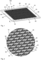
- Figure 1 depicts a flow plate 100 for a humidifier 1000, in particular a humidifier 1000 for a fuel cell system, according to an embodiment of the invention, in an isometric view from a first side 18, whereas in Figure 2 a magnified section W of the flow plate 100 according to Figure 1 is depicted.
- the flow plate 100 comprises a frame 50.
- the frame 50 surrounds a flow field body 20 which is connected or integral with the frame 50.
- the flow field body 20 comprises a base plane 10 as a structure element.
- the flow field body 20 serves for guiding a first fluid 60, e.g. an exhaust gas of the fuel cell system, on one of the first or second sides 28, 28 of the flow plate 100 along the base plane 10 of the flow plate 100.
- a first fluid 60 e.g. an exhaust gas of the fuel cell system
- the flow field body 20 has a corrugated surface at least on one side 18, thus providing a plurality of support elements 30 protruding from the base plane 10 of the flow field body 20.
- the support elements 30 are arranged in a matrix-like manner in lines and rows 42, 43.
- the lines of support elements 30 extend in a first direction 16 and rows 42, 43 of support elements 30 extend in a second direction 26 perpendicular to the first direction 16.
- the first and the second direction 16, 26 in Figure 1 correspond to edges of the flow plate 100, but it may also be advantageous, that the first and the second direction 16, 26 are oriented in a different way. Yet, other orientations, where the two directions 16, 26 are somehow oblique oriented to each other may also be possible and could be advantageous under certain requirements.
- the support elements 30 in successive lines and rows are arranged offset from each other.
- the support elements 30 protrude from at least one of the first and second side 18, 28 of the base plate 10.
- the flow plate 100 comprises opposing front ends 12, 14 along the first direction 16 and opposing longitudinal ends 22, 24 along the second direction 26.
- First through-openings 52, 54 extended parallel to the front ends 12, 14 are arranged in the base plane 10 for feeding the first fluid 60 to the at least one flow field body 20 and opposing second through-openings 56, 58 extended parallel to the longitudinal ends 22, 24 are arranged for feeding the second fluid 62 to the at least one flow field body 20 of an adjacent flow plate 100, when in an intentional use the flow plates 100 are stacked in a stack plate device 400.
- the first fluid 60 and the second fluid 62 by this way may be guided to different sides 18, 28 of the base plate 10.
- Openings 34 are arranged in all four corners of the flow plate 100 for feeding through a tie-rod 1012 when stacking the flow plates 100 to a stack plate device 400, as is to be seen in Figures 11 , 12 .
- the support elements 30 are protruding at an angle 40 close to, but less than 90 degrees against the base plane 10 in at least one of the first and second directions 16, 26.
- the angle 40 is sketched in Figure 2 for support elements 30 of two neighboring rows 42, 43.
- the support elements 30 are shaped hook-like, in particular, wherein the free end 32 of the support element 30 is bent towards the base plane 10, relative to a plumb line direction oriented perpendicularly to the base plane 10.
- the support elements 30 are arranged at periodic distances from one another.
- bent free ends 32 of support elements 30 in one row 42 and in a neighboring next row 43 are oriented facing each other.
- the support elements 30 in the same row 42 are bent in a first direction and the support elements 30 in an adjacent row 43 are bent in a direction opposing the first direction.
- the support elements 30 arranged in the same line could be bent in a first direction and the support elements 30 in an adjacent next line are bent in a direction opposing the first direction.
- an advantageous guiding of the fluid flow directed to the membrane 110 may be achieved enhancing the moisture transfer process and on the same time supporting the membrane 110 against the fluid pressure.
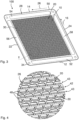
- Figure 3 depicts the flow plate 100 according to Figure 1 from the second side 28, whereas in Figure 4 a magnified section Y of the view of the flow plate 100 according to Figure 3 is depicted.
- Through-holes 48 adjacent to the support elements 30 may be recognized.
- the through-holes 48 may exist due to the manufacturing process of the support elements 30, e.g., the support elements 30 may be stamped out of the base plane 10, thus leaving through-holes 48 in the base plane 10.
- the through-holes 48 may also contribute to an advantageous fluid flow guiding of the flow field body 20.
- the through-holes 48 correspond in area and shape to dimensions of the support elements 30.
- the flow field body 20 with the support elements 30 may be connected or integral with the frame 50, according to manufacturing requirements.
- the flow field body 20 could be made in an injection molding process with some plastic material together with the frame 50 as one part which offers a relatively cost efficient manufacturing process.
- an inlay part to the circumferential frame 50 may be provided, wherein the support elements 30 are part of the inlay part.
- the inlay part can easily be modified or exchanged when other support elements 30 should be used for a specific flow plate 100 and humidifier design with altered fluid flow conditions.
- Support elements 30 may advantageously be arranged on one side 18, 28 of the base plane 10 as well as on both opposing sides 18, 28, according to the fluid flow conditions to be required.
- the support elements 30 on one side 18, 28 of the base plane 10 may be different from the support elements 30 on the other side 18, 28.
- the support elements 30 on one side 18, 28 of the base plane 10 may differ in height above the base plane 10 and/or in shape and/or orientation in the base plane 10 from the support elements 30 on the other side 18, 28.
- FIG. 5 a flow plate 100 according to a further embodiment of the invention is depicted, in an isometric view, whereas in Figure 6 a magnified section Z of the flow plate 100 according to Figure 5 is shown.
- the support elements 30 are formed in a honeycomb-like shape.
- the support elements 30 are segments of adjacent hexagon-like structures.
- honeycomb shaped support elements 30 are arranged not totally flat in the base plane 10 of the flow plate 100, but are configured with parts of the structure extending from the base plane 10 on one side 18 of the flow plate 100 and other parts extending on the other side 28.
- Figure 7 depicts a flow plate 100 according to a further embodiment of the invention, in an isometric view, whereas in Figure 8 a magnified section Z of the flow plate 100 according to Figure 7 is depicted.
- the support elements 30 are formed as parallel longitudinal embossments 44 oriented at least partly along the first and/or the second direction 16, 26.
- the support elements 30 have at least partly breakthroughs 46 through the embossments 44 in a direction oblique to an extension of the protrusions 44.
- the breakthroughs 46 may be shaped waveform-like.
- the embossments 44 may protrude in a first region, e.g. in the lower part of the flow plate 100, referring to the viewing plane, to the first side 18 of the flow plate 100 and in a second region, e.g. the upper part of the flow plate 100 to the second side 28, which means the embossments 44 are realized as depressions in the first side 18. In between the two parts there may be a continuous transition in the embossments 44.
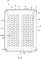
- FIG 9 a top view of the flow plate 100 according to Figure 7 is depicted, with a cutting line G-G for a cut view through part of an embossment 44.
- Figure 10 depicts the magnified cut view along the line G-G according to Figure 9 through three stacked flow plates 100.
- the three flow plates 100 are stacked atop of each other with semipermeable membranes 110 stacked between the flow plates 100.
- the embossments 44 of the three flow plates 100 are alternately oriented in different directions 16, 26.
- the embossments 44 of the uppermost and the lowermost flow plate 100 are oriented in the first direction 16, whereas the embossments 44 of the middle flow plate 100 are oriented transversely hereto in the second direction 26, as may be recognized from the cut view.
- the semipermeable membrane 110 is pressed by the embossments 44 of one flow plate 100 against the second side 28 of the neighboring flow plate 100 atop of the first flow plate 100.
- Gaskets 112 are arranged between the flow plates 100 in order to seal the through-openings 52, 54 (in Figure 10 the first through-openings 52 are visible).
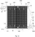
- Figure 11 depicts a humidifier 1000, in particular for a fuel cell system, according to an embodiment of the invention, in an isometric view, whereas Figure 12 depicts a cut view of the humidifier 100 according to Figure 11 .
- the humidifier 1000 comprises flow plates 100, which are arranged in a stack plate device 400 in a stacking direction 500, as marked in the Figures.
- a semipermeable layer composite 110 comprising at least one water exchange membrane 110 is arranged between two adjacent flow plates 100 of the stack plate device 400 each.
- the stack plate device 400 is enclosed on both ends with housing parts 1002, 1003.
- Fluid inlets 1004, 1008 for the first and the second fluid 60, 62 are integrated in the first housing part 1002, whereas fluid outlets 1006, 1010 are integrated in the second housing part 1003.
- Stack plate device 400 and housing parts 1002, 1003 are fixed by four tie rods 1012, mounted through openings 34 in the corners of the flow plates 100.
- Gaskets 112 for sealing the first through-openings 52, 54 are also to be seen in the cut view.
Landscapes
- Chemical & Material Sciences (AREA)
- Chemical Kinetics & Catalysis (AREA)
- Life Sciences & Earth Sciences (AREA)
- Engineering & Computer Science (AREA)
- Manufacturing & Machinery (AREA)
- Sustainable Development (AREA)
- Sustainable Energy (AREA)
- Electrochemistry (AREA)
- General Chemical & Material Sciences (AREA)
- Fuel Cell (AREA)
Abstract
The invention relates to a flow plate (100) for a humidifier (1000), in particular the humidifier (1000) for a fuel cell system, the flow plate (100) comprising a frame (50) and a flow field body (20), the frame (50) surrounding the flow field body (20) being connected or integral with the frame (50). The flow field body (20) has a corrugated surface at least on one side (18), the flow field body (20) comprising a plurality of support elements (30) protruding from a base plane (10) of the flow field body (20) and being arranged in lines and rows (42, 43). The lines of support elements (30) extend in a first direction (16) and the rows (42, 43) of support elements (30) extend in a second direction (26) different from the first direction (16). The support elements (30) in successive lines and rows are arranged offset from each other.
Description
- The invention relates to a flow plate for a humidifier, in particular a humidifier for a fuel cell system, as well as a humidifier with flow plates.
- Humidifiers are used for example to humidify process gas for fuel cells which are operated with molecular hydrogen and/or oxygen or air for electricity generation. The process gases supplied to the fuel cell are for this reason usually set to a desired, stable humidity in a humidifier. A humidifier comprises flow plates which are usually provided with channel structures, wherein the channels adjoin a water transfer medium, typically in the form of a semipermeable layer such as a water-transfer membrane. An assembly usually provides a plurality of flow plates, between which there are arranged water transfer membranes.
- For example, on one side of a semipermeable layer a moist gas, e.g. an exhaust gas from the fuel cell, is guided through the channels of an adjacent flow plate, and on the opposite side of the semipermeable layer a dry gas, e.g. fresh air, is passed through channels of a second flow plate. In this case, the moist gas on one side of the semipermeable layer gives off moisture to the semipermeable layer, whereas on the opposite side the semipermeable layer gives off moisture to the dry gas.
-
WO 2018/055130 A1 discloses a flow plate for a humidifier, and to such a humidifier having a plurality of flow plates and water exchange membranes. Humidifiers of this kind are used in electrochemical systems, among other things. The flow plate has a flow field with a plurality of free-standing support elements, wherein the support elements extend, at least in sections, perpendicular to the flat surface plane of the flow plate. Gas to be humidified or gas giving off moisture flows on the flow field. In the humidifier, the flow plates are arranged in a stack, wherein a membrane composite having at least one water exchange membrane is arranged between each pair of adjacent flow plates in the stack. - It is an object of the invention to provide an improved flow plate for a humidifier, in particular a humidifier for a fuel cell system.
- Another object is to provide an improved humidifier with such flow plates.
- According to an aspect of the invention, the object is achieved by a flow plate for a humidifier, in particular a humidifier for a fuel cell system, comprising a frame, the frame surrounding a flow field body being connected or integral with the frame, wherein the flow field body has a corrugated surface at least on one side, the flow field body comprising a plurality of support elements protruding from a base plane of the flow field body and being arranged in lines and rows, wherein the lines of support elements extend in a first direction and rows of support elements extend in a second direction different from the first direction, wherein the support elements in successive lines and rows are arranged offset from each other.
- According to a further aspect of the invention, the further object is achieved by a humidifier with flow plates, wherein flow plates are arranged in a stack plate device and wherein a semipermeable layer composite comprising at least one water exchange membrane is arranged between two adjacent flow plates of the stack plate device each.
- Advantageous embodiments are described in the dependent claims, the description and the drawings.
- According to an aspect of the invention, a flow plate for a humidifier, in particular a humidifier for a fuel cell system, is proposed, comprising a frame, the frame surrounding a flow field body being connected or integral with the frame. The flow field body has a corrugated surface at least on one side, the flow field body comprising a plurality of support elements protruding from a base plane of the flow field body and being arranged in lines and rows. The lines of support elements extend in a first direction and rows of support elements extend in a second direction different from the first direction. The support elements in successive lines and rows are arranged offset from each other.
- Humidifiers for the operation of a fuel cell system essentially consist of several flow plates which accommodate a semipermeable layer, such as a semipermeable membrane. This membrane is circumferentially sealed by frames of neighboring flow plates. The flow plates are sealed tightly to each other on the outside. Supply air and exhaust gas, respectively, flows on the two sides of the membrane with the effect that moisture (H2O) is exchanged to a certain extent via the membrane medium. The supply air can be humidified by moisture from the exhaust gas through the semipermeable layer.
- The flow plates can be formed from plastic, for example PA6.6 (polyamide), PPA (polyphtalamide), PPS (polyphenylene sulfide), or TPX (polymethylpentene). Alternatively, the flow plates can be formed of sheet metal, for example stainless steel.
- The arrangement of the support elements in lines and rows may be in a matrix-like manner.
- The semipermeable layer thus separates the exhaust gas flow channel from the supply air flow channel. The semipermeable layer can be designed, for example, as a PFSA (perfluorosulfonic acid) membrane. Such membranes are also commonly used as proton exchange membranes. The membrane is airtight but permeable to moisture.
- The pressure levels of the wet exhaust gas and the dry supply air on the different sides of the membrane are different. To optimize the efficiency of the moisture exchange and at the same time to support the membranes against the pressure difference, the interstices between neighboring membranes can be filled with spacer elements. The design of the air flow guiding and supporting geometry may advantageously be designed according to the case of application and requirements. In general, the more intensively the air flow is directed against the membrane, the better is the water transfer. However, the resulting pressure loss in the flow channel reacts proportional. This pressure loss may not exceed a certain level as pressure loss is synonymous with the power to be provided. Therefore, with regard to support geometries, a compromise between a support area to avoid buckling of the membrane with narrow gaps, which means pressure loss, and an open flow area may advantageously be chosen.
- The air flow funnels can be integrally molded as part of the frame or inserted separately as inserts. The designs can be different on the dry air side and on the wet air side. Since the higher pressure level prevails on the dry air side, the support elements may also be provided only on the wet air side. An air flow deflection geometry always appears to be advantageous.
- The first and the second direction may be oriented perpendicularly according to outer edges of the flow plate. Yet, other orientations, where the two directions are somehow oblique to each other are possible.
- Advantageously a higher efficiency of the moisture transfer process may be achieved with flow plates according to the invention. A cost reduction may especially be achieved when the flow plates are manufactured as one-piece from the tub manufacturing process. Thus, favorably, additional assembly of the flow plates may be avoided. Individually matched geometries may also favorably be achieved by such flow plates.
- According to a favorable embodiment of the flow plate, the support elements may be protruding, at least in sections, at an angle of less than 90 degrees against the base plane in at least one of the first and second directions. Thus, an advantageous guiding of the fluid flow directed to the membrane may be achieved enhancing the moisture transfer process and on the same time supporting the membrane against the fluid pressure.
- According to a favorable embodiment of the flow plate, the support elements may be shaped hook-like. In particular, the free end of the support element may be bent towards the base plane, relative to a plumb line direction oriented perpendicularly to the base plane. Advantageously the contact area of the support elements to the membrane may be optimized for a long lifetime.
- According to a favorable embodiment of the flow plate, the support elements may be arranged at periodic distances from one another. This may optimize the fluid flow pattern in order to achieve an advantageous moisture transfer.
- According to a favorable embodiment of the flow plate, bent free ends of support elements in one row and in a neighboring next row may be oriented facing each other. Thus, supporting the membrane by the support elements may be optimized. Particularly the support area may thus be locally enlarged.
- According to a favorable embodiment of the flow plate, the support elements in the same row may be bent in a first direction and the support elements in an adjacent row may be bent in a direction opposing the first direction. Alternatively, the support elements arranged in the same line may be bent in a first direction and the support elements in an adjacent next line may be bent in a direction opposing the first direction. Advantageously, the manufacturing process for the flow plates may be optimized by such a design.
- According to a favorable embodiment of the flow plate, the support elements may be formed in a honeycomb-like shape. In particular, the support elements may be segments of adjacent hexagon-like structures. This further embodiment realizes a different design of a flow field body with a plurality of openings through the flow plate. The honeycomb shaped support elements are arranged not totally flat in the base plane of the flow plate, but are configured with parts of the structure extending from the plane on one side of the flow plate and other parts extending on the other side. Thus an advantageous guiding of the fluid flow directed to the membrane may be achieved enhancing the moisture transfer process and on the same time supporting the membrane against the fluid pressure.
- According to a favorable embodiment of the flow plate, the support elements may be formed as parallel longitudinal embossments oriented at least partly along the first and/or the second direction, having at least partly breakthroughs through the embossments in a direction oblique to an extension of the protrusions. Thus, supporting the membrane by the support elements may be optimized by long embossments. Particularly the support area may thus be locally enlarged. By the same time an advantageous guiding of the fluid flow directed to the membrane may be achieved enhancing the moisture transfer process.
- According to a favorable embodiment of the flow plate, an inlay part to the circumferential frame may be provided, wherein the support elements are part of the inlay part. Thus, a flexible design of the flow field body may be combined with a cost efficient manufacturing process. The inlay part can easily be modified or exchanged when other support elements should be used for a specific flow plate and humidifier design with altered fluid flow conditions.
- According to a favorable embodiment of the flow plate, support elements may be arranged on both opposing sides of the base plane. By this way, a stable support of the membrane against different pressure conditions of the fluid flows may be achieved.
- According to a favorable embodiment of the flow plate, the support elements on one side of the base plane may be different from the support elements on the other side. In particular, the support elements on one side of the base plane may differ in height above the base plane and/or in shape and/or orientation in the base plane from the support elements on the other side. This may account for the different boundary conditions of the supply air and the exhaust gas, since the higher pressure level prevails on the dry supply air side.
- According to a favorable embodiment, the flow plate may comprise through-holes adjacent to the support elements. In particular, the through-holes may correspond in area and shape to dimensions of the support elements. The through-holes may exist due to the manufacturing process of the support elements, e.g., the support elements may be stamped out of the base plane, thus leaving through-holes in the base plane. Advantageously, the through-holes may also contribute to an advantageous fluid flow guiding of the flow field body.
- According to a favorable embodiment of the flow plate, first through-openings extended parallel to the front ends may be arranged in the base plane for feeding the first fluid to the at least one flow field body and opposing second through-openings extended parallel to the longitudinal ends may be arranged for feeding the second fluid to the at least one flow field body of an adjacent flow plate, when in an intentional use the flow plates are stacked in a stack plate device. Thus, the first fluid, e.g. the exhaust gas, and the second fluid, e.g. the supply air, may advantageously be fed in flow channels through the stacked flow plates and may be branched to the flow field bodies of the different flow plates.
- According to an aspect of the invention, a humidifier, in particular for a fuel cell system, with flow plates may be proposed, wherein flow plates are arranged in a stack plate device and wherein a semipermeable layer composite comprising at least one water exchange membrane is arranged between two adjacent flow plates of the stack plate device each.
- The humidifier represents a flat membrane humidifier. A first, moist or water-rich fluid, for example exhaust gas from fuel cells, flows in one group of flow channels, while a second, dry fluid, for example supply air for the fuel cells, flows in another group of flow channels. The second dry fluid can be moistened by the first fluid via the semipermeable membranes.
- The stacked flow plates may be axially floatingly sealed as a stack plate device and may be sealed in the housing via two axially acting seals located respectively at the ends of the housing comprising the inlet side and outlet side of the first and second fluid.
- The housing of the humidifier can be made of metal, for example aluminum. Alternatively, it is also possible that the housing is made of plastics, for example PPS, PPA (polyphtalamide), PA (polyamide).
- The housing can be made in two housing parts with the fluid inlets and outlets where the stack plate device is located and sealed in between the housing parts.
- The present invention together with the above-mentioned and other objects and advantages may best be understood from the following detailed description of the embodiments, but not restricted to the embodiments, wherein is shown in:
-
Figure 1 is a flow plate for a humidifier, in particular a humidifier for a fuel cell system, according to an embodiment of the invention, in an isometric view from a first side; -
Figure 2 is a magnified section W of the flow plate according toFigure 1 ; -
Figure 3 is the flow plate according toFigure 1 from a second side; -
Figure 4 is a magnified section Y of the view of the flow plate according toFigure 3 ; -
Figure 5 is a flow plate according to a further embodiment of the invention, in an isometric view; -
Figure 6 is a magnified section Z of the flow plate according toFigure 5 ; -
Figure 7 is a flow plate according to a further embodiment of the invention, in an isometric view; -
Figure 8 is a magnified section Z of the flow plate according toFigure 7 ; -
Figure 9 is a top view of the flow plate according toFigure 7 ; -
Figure 10 is a magnified cut view along the line G-G according toFigure 9 through three stacked flow plates; -
Figure 11 is a humidifier, in particular for a fuel cell system, according to an embodiment of the invention, in an isometric view; and -
Figure 12 is a cut view of the humidifier according toFigure 11 . - In the drawings, like elements are referred to with equal reference numerals. The drawings are merely schematic representations, not intended to portray specific parameters of the invention. Moreover, the drawings are intended to depict only typical embodiments of the invention and therefore should not be considered as limiting the scope of the invention.
-
Figure 1 depicts aflow plate 100 for ahumidifier 1000, in particular ahumidifier 1000 for a fuel cell system, according to an embodiment of the invention, in an isometric view from afirst side 18, whereas inFigure 2 a magnified section W of theflow plate 100 according toFigure 1 is depicted. - The
flow plate 100 comprises aframe 50. Theframe 50 surrounds aflow field body 20 which is connected or integral with theframe 50. Theflow field body 20 comprises abase plane 10 as a structure element. - The
flow field body 20 serves for guiding afirst fluid 60, e.g. an exhaust gas of the fuel cell system, on one of the first orsecond sides flow plate 100 along thebase plane 10 of theflow plate 100. - The
flow field body 20 has a corrugated surface at least on oneside 18, thus providing a plurality ofsupport elements 30 protruding from thebase plane 10 of theflow field body 20. Thesupport elements 30 are arranged in a matrix-like manner in lines androws support elements 30 extend in afirst direction 16 androws support elements 30 extend in asecond direction 26 perpendicular to thefirst direction 16. The first and thesecond direction Figure 1 correspond to edges of theflow plate 100, but it may also be advantageous, that the first and thesecond direction directions - Advantageously the
support elements 30 in successive lines and rows are arranged offset from each other. Thesupport elements 30 protrude from at least one of the first andsecond side base plate 10. - The
flow plate 100 comprises opposing front ends 12, 14 along thefirst direction 16 and opposing longitudinal ends 22, 24 along thesecond direction 26. - First through-
openings base plane 10 for feeding thefirst fluid 60 to the at least oneflow field body 20 and opposing second through-openings second fluid 62 to the at least oneflow field body 20 of anadjacent flow plate 100, when in an intentional use theflow plates 100 are stacked in astack plate device 400. Thefirst fluid 60 and thesecond fluid 62 by this way may be guided todifferent sides base plate 10. -
Openings 34 are arranged in all four corners of theflow plate 100 for feeding through a tie-rod 1012 when stacking theflow plates 100 to astack plate device 400, as is to be seen inFigures 11 ,12 . - As particularly may be seen from
Figure 2 , thesupport elements 30 are protruding at anangle 40 close to, but less than 90 degrees against thebase plane 10 in at least one of the first andsecond directions angle 40 is sketched inFigure 2 forsupport elements 30 of two neighboringrows - The
support elements 30 are shaped hook-like, in particular, wherein thefree end 32 of thesupport element 30 is bent towards thebase plane 10, relative to a plumb line direction oriented perpendicularly to thebase plane 10. - As may also be seen, the
support elements 30 are arranged at periodic distances from one another. In the embodiment shown inFigure 2 , bent free ends 32 ofsupport elements 30 in onerow 42 and in a neighboringnext row 43 are oriented facing each other. Thesupport elements 30 in thesame row 42 are bent in a first direction and thesupport elements 30 in anadjacent row 43 are bent in a direction opposing the first direction. Alternately, thesupport elements 30 arranged in the same line could be bent in a first direction and thesupport elements 30 in an adjacent next line are bent in a direction opposing the first direction. - Thus an advantageous guiding of the fluid flow directed to the
membrane 110 may be achieved enhancing the moisture transfer process and on the same time supporting themembrane 110 against the fluid pressure. -
Figure 3 depicts theflow plate 100 according toFigure 1 from thesecond side 28, whereas inFigure 4 a magnified section Y of the view of theflow plate 100 according toFigure 3 is depicted. - Particularly in
Figure 4 , details of thesupport elements 30 are to be seen from their backside. Through-holes 48 adjacent to thesupport elements 30 may be recognized. The through-holes 48 may exist due to the manufacturing process of thesupport elements 30, e.g., thesupport elements 30 may be stamped out of thebase plane 10, thus leaving through-holes 48 in thebase plane 10. Advantageously, the through-holes 48 may also contribute to an advantageous fluid flow guiding of theflow field body 20. In particular, the through-holes 48 correspond in area and shape to dimensions of thesupport elements 30. - The
flow field body 20 with thesupport elements 30 may be connected or integral with theframe 50, according to manufacturing requirements. Theflow field body 20 could be made in an injection molding process with some plastic material together with theframe 50 as one part which offers a relatively cost efficient manufacturing process. - Alternatively, an inlay part to the
circumferential frame 50 may be provided, wherein thesupport elements 30 are part of the inlay part. Thus, a flexible design of theflow field body 20 may be combined with a cost efficient manufacturing process. The inlay part can easily be modified or exchanged whenother support elements 30 should be used for aspecific flow plate 100 and humidifier design with altered fluid flow conditions. -
Support elements 30 may advantageously be arranged on oneside base plane 10 as well as on both opposingsides support elements 30 on oneside base plane 10 may be different from thesupport elements 30 on theother side support elements 30 on oneside base plane 10 may differ in height above thebase plane 10 and/or in shape and/or orientation in thebase plane 10 from thesupport elements 30 on theother side - In
Figure 5 aflow plate 100 according to a further embodiment of the invention is depicted, in an isometric view, whereas inFigure 6 a magnified section Z of theflow plate 100 according toFigure 5 is shown. - In this embodiment, the
support elements 30 are formed in a honeycomb-like shape. In particular, which may be seen inFigure 6 , thesupport elements 30 are segments of adjacent hexagon-like structures. - The honeycomb shaped
support elements 30 are arranged not totally flat in thebase plane 10 of theflow plate 100, but are configured with parts of the structure extending from thebase plane 10 on oneside 18 of theflow plate 100 and other parts extending on theother side 28. -
Figure 7 depicts aflow plate 100 according to a further embodiment of the invention, in an isometric view, whereas inFigure 8 a magnified section Z of theflow plate 100 according toFigure 7 is depicted. - In this embodiment, the
support elements 30 are formed as parallel longitudinal embossments 44 oriented at least partly along the first and/or thesecond direction support elements 30 have at least partlybreakthroughs 46 through the embossments 44 in a direction oblique to an extension of the protrusions 44. Thebreakthroughs 46 may be shaped waveform-like. - As may be seen from
Figure 7 , the embossments 44 may protrude in a first region, e.g. in the lower part of theflow plate 100, referring to the viewing plane, to thefirst side 18 of theflow plate 100 and in a second region, e.g. the upper part of theflow plate 100 to thesecond side 28, which means the embossments 44 are realized as depressions in thefirst side 18. In between the two parts there may be a continuous transition in the embossments 44. - In
Figure 9 a top view of theflow plate 100 according toFigure 7 is depicted, with a cutting line G-G for a cut view through part of an embossment 44. -
Figure 10 depicts the magnified cut view along the line G-G according toFigure 9 through three stackedflow plates 100. - The three
flow plates 100 are stacked atop of each other withsemipermeable membranes 110 stacked between theflow plates 100. The embossments 44 of the threeflow plates 100 are alternately oriented indifferent directions lowermost flow plate 100 are oriented in thefirst direction 16, whereas the embossments 44 of themiddle flow plate 100 are oriented transversely hereto in thesecond direction 26, as may be recognized from the cut view. Thesemipermeable membrane 110 is pressed by the embossments 44 of oneflow plate 100 against thesecond side 28 of the neighboringflow plate 100 atop of thefirst flow plate 100. -
Gaskets 112 are arranged between theflow plates 100 in order to seal the through-openings 52, 54 (inFigure 10 the first through-openings 52 are visible). -
Figure 11 depicts ahumidifier 1000, in particular for a fuel cell system, according to an embodiment of the invention, in an isometric view, whereasFigure 12 depicts a cut view of thehumidifier 100 according toFigure 11 . - The
humidifier 1000 comprisesflow plates 100, which are arranged in astack plate device 400 in a stackingdirection 500, as marked in the Figures. In thestack plate device 400, a semipermeable layer composite 110 comprising at least onewater exchange membrane 110 is arranged between twoadjacent flow plates 100 of thestack plate device 400 each. - The
stack plate device 400 is enclosed on both ends withhousing parts -
Fluid inlets second fluid first housing part 1002, whereasfluid outlets second housing part 1003. -
Stack plate device 400 andhousing parts tie rods 1012, mounted throughopenings 34 in the corners of theflow plates 100. - In the cut view in
Figure 12 the flow of the first fluid 60 from theinlet 1004 through theflow plates 100 to theoutlet 1006 is marked by arrows. Theoutlet 1010 is also to be seen as a projection, because it does not lie in the cutting plane. -
Gaskets 112 for sealing the first through-openings -
- 10 base plane
- 12 front end
- 14 front end
- 16 first direction
- 18 first side
- 20 flow field body
- 22 longitudinal end
- 24 longitudinal end
- 26 second direction
- 28 second side
- 30 support element
- 32 hook-like end
- 34 opening
- 40 angle
- 42 row
- 43 row
- 44 embossment
- 46 breakthrough
- 48 through-hole
- 50 frame
- 52 first through-opening
- 54 first through-opening
- 56 second through-opening
- 58 second through-opening
- 60 first fluid (exhaust gas)
- 62 second fluid (supply air)
- 100 flow plate
- 110 semipermeable layer
- 112 gasket
- 400 stack plate device
- 500 stacking direction
- 1000 humidifier
- 1002 housing part
- 1003 housing part
- 1004 inlet first fluid
- 1006 outlet first fluid
- 1008 inlet second fluid
- 1010 outlet second fluid
- 1012 tie rod
Claims (14)
- A flow plate (100) for a humidifier (1000), in particular the humidifier (1000) for a fuel cell system, the flow plate (100) comprising:a frame (50); anda flow field body (20), the frame (50) surrounding the flow field body (20) being connected or integral with the frame (50),wherein the flow field body (20) has a corrugated surface at least on one side (18), the flow field body (20) comprising a plurality of support elements (30) protruding from a base plane (10) of the flow field body (20) and being arranged in lines and rows (42, 43), the lines of the support elements (30) extending in a first direction (16) and the rows (42, 43) of the support elements (30) extending in a second direction (26) different from the first direction (16), andwherein the support elements (30) in successive lines and rows are arranged offset from each other.
- The flow plate according to claim 1, wherein the support elements (30) are protruding, at least in sections, at an angle (40) of less than 90 degrees against the base plane (10) in at least one of the first and second directions (16, 26).
- The flow plate according to claim 1 or 2, wherein the support elements (30) are shaped hook-like, in particular, wherein a free end (32) of the support element (30) is bent towards the base plane (10), relative to a plumb line direction oriented perpendicularly to the base plane (10).
- The flow plate according to any one of the preceding claims, wherein the support elements (30) are arranged at periodic distances from one another.
- The flow plate according to any one of the preceding claims, wherein bent free ends (32) of the support elements (30) in one row (42) and in a neighboring next row (43) are oriented facing each other.
- The flow plate according to any one of the claims 4 or 5, wherein the support elements (30) in the same row (42) are bent in a first direction, and the support elements (30) in an adjacent row (43) are bent in a direction opposing the first direction, or
wherein the support elements (30) arranged in the same line are bent in a first direction, and the support elements (30) in an adjacent next line are bent in a direction opposing the first direction. - The flow plate according to claim 1, wherein the support elements (30) are formed in a honeycomb-like shape, in particular, wherein the support elements (30) are segments of adjacent hexagon-like structures.
- The flow plate according to claim 1, wherein the support elements (30) are formed as parallel longitudinal embossments (44) oriented at least partly along the first and/or the second direction (16, 26), and having at least partly breakthroughs (46) through the embossments (44) in a direction oblique to an extension of the embossments (44).
- The flow plate according to any one of the preceding claims, wherein an inlay part to the circumferential frame (50) is provided, and
wherein the support elements (30) are part of the inlay part. - The flow plate according to any one of the preceding claims, wherein the support elements (30) are arranged on both opposing sides (18, 28) of the base plane (10).
- The flow plate according to claim 10, wherein the support elements (30) on one side (18, 28) of the base plane (10) are different from the support elements (30) on the other side (18, 28), in particular, wherein the support elements (30) on one side (18, 28) of the base plane (10) differ in height above the base plane (10) and/or in shape and/or in orientation in the base plane (10) from the support elements (30) on the other side (18, 28).
- The flow plate according to any one of the preceding claims, further comprising through-holes (48) adjacent to the support elements (30), in particular, wherein the through-holes (48) correspond in area and shape to dimensions of the support elements (30).
- The flow plate according to any one of the preceding claims, wherein first through-openings (52, 54) extended parallel to front ends (12, 14) are arranged in the base plane (10) for feeding a first fluid (60) to the at least one flow field body (20) and opposing second through-openings (56, 58) extended parallel to longitudinal ends (22, 24) are arranged for feeding a second fluid (62) to the at least one flow field body (20) of an adjacent flow plate (100), when the flow plates (100) are stacked in a stack plate device (400).
- A humidifier (1000), in particular for a fuel cell system, the humidifier (1000) comprising flow plates (100) according to any one of the preceding claims,wherein the flow plates (100) are arranged in a stack plate device (400), andwherein a semipermeable layer composite (110) comprising at least one water exchange membrane (110) is arranged between each pair of the adjacent flow plates (100) of the stack plate device (400).
Priority Applications (3)
| Application Number | Priority Date | Filing Date | Title |
|---|---|---|---|
| EP23158193.5A EP4420766A1 (en) | 2023-02-23 | 2023-02-23 | Flow plate and humidifier for a fuel cell system |
| US18/411,013 US20240291001A1 (en) | 2023-02-23 | 2024-01-11 | Flow plate and humidifier for fuel cell system |
| CN202410202745.XA CN118538956A (en) | 2023-02-23 | 2024-02-23 | Flow plates and humidifiers for fuel cell systems |
Applications Claiming Priority (1)
| Application Number | Priority Date | Filing Date | Title |
|---|---|---|---|
| EP23158193.5A EP4420766A1 (en) | 2023-02-23 | 2023-02-23 | Flow plate and humidifier for a fuel cell system |
Publications (1)
| Publication Number | Publication Date |
|---|---|
| EP4420766A1 true EP4420766A1 (en) | 2024-08-28 |
Family
ID=85380829
Family Applications (1)
| Application Number | Title | Priority Date | Filing Date |
|---|---|---|---|
| EP23158193.5A Pending EP4420766A1 (en) | 2023-02-23 | 2023-02-23 | Flow plate and humidifier for a fuel cell system |
Country Status (3)
| Country | Link |
|---|---|
| US (1) | US20240291001A1 (en) |
| EP (1) | EP4420766A1 (en) |
| CN (1) | CN118538956A (en) |
Families Citing this family (2)
| Publication number | Priority date | Publication date | Assignee | Title |
|---|---|---|---|---|
| DE102021119823A1 (en) * | 2021-07-30 | 2023-02-02 | Mann+Hummel Gmbh | Humidification device with channel plates, carrier plate and channel plate for a humidification device |
| EP4378570A1 (en) * | 2022-12-01 | 2024-06-05 | MANN+HUMMEL GmbH | Stack plate, stack plate device and humidifier |
Citations (6)
| Publication number | Priority date | Publication date | Assignee | Title |
|---|---|---|---|---|
| JPS4852174U (en) * | 1971-10-14 | 1973-07-06 | ||
| US4053418A (en) * | 1975-10-08 | 1977-10-11 | Baxter Travenol Laboratories, Inc. | Embossed membrane support |
| DE102014100659A1 (en) * | 2014-01-21 | 2015-07-23 | Dauborn Membransysteme Gmbh | Support insert of a membrane module |
| US20150314241A1 (en) * | 2012-12-13 | 2015-11-05 | 3M Innovative Properties Company | Constructions for fluid membrane separation devices |
| WO2018055130A1 (en) | 2016-09-23 | 2018-03-29 | Reinz-Dichtungs-Gmbh | Flow plate for a humidifier |
| US20190126207A1 (en) * | 2016-04-27 | 2019-05-02 | Toray Industries, Inc. | Separation membrane element |
Family Cites Families (10)
| Publication number | Priority date | Publication date | Assignee | Title |
|---|---|---|---|---|
| US3963621A (en) * | 1974-10-21 | 1976-06-15 | Baxter Laboratories, Inc. | Membrane diffusion device having ribbed membrane support |
| US4053417A (en) * | 1975-10-08 | 1977-10-11 | Baxter Travenol Laboratories, Inc. | Embossed support member with high and low skip ribs |
| GB2390738B (en) * | 2002-07-09 | 2005-05-11 | Intelligent Energy Ltd | Fuel cell direct water injection |
| WO2004091023A2 (en) * | 2003-04-08 | 2004-10-21 | Altercell Fuel Cell Technology Aps | Fuel cell |
| JP2012531256A (en) * | 2009-06-24 | 2012-12-10 | ステイト オブ オレゴン アクティング バイ アンド スルー ザ ステイト ボード オブ ハイヤー エデュケーション オン ビハーフ オブ オレゴン ステイト ユニバーシティー | Microfluidic device for dialysis |
| US9735438B2 (en) * | 2011-01-13 | 2017-08-15 | Dana Canada Corporation | Humidifier for fuel cell systems |
| DE102012019541A1 (en) * | 2011-10-24 | 2013-04-25 | Mann+Hummel Gmbh | Humidifying device for a fuel cell |
| DE102015122144A1 (en) * | 2015-12-17 | 2017-06-22 | Volkswagen Ag | Humidifier with integrated water separator for a fuel cell system, fuel cell system and vehicle with such a |
| DE202016105307U1 (en) * | 2016-09-23 | 2018-01-09 | Reinz-Dichtungs-Gmbh | Flow plate for a humidifier |
| DE202016105309U1 (en) * | 2016-09-23 | 2018-01-09 | Reinz-Dichtungs-Gmbh | humidifier |
-
2023
- 2023-02-23 EP EP23158193.5A patent/EP4420766A1/en active Pending
-
2024
- 2024-01-11 US US18/411,013 patent/US20240291001A1/en active Pending
- 2024-02-23 CN CN202410202745.XA patent/CN118538956A/en active Pending
Patent Citations (6)
| Publication number | Priority date | Publication date | Assignee | Title |
|---|---|---|---|---|
| JPS4852174U (en) * | 1971-10-14 | 1973-07-06 | ||
| US4053418A (en) * | 1975-10-08 | 1977-10-11 | Baxter Travenol Laboratories, Inc. | Embossed membrane support |
| US20150314241A1 (en) * | 2012-12-13 | 2015-11-05 | 3M Innovative Properties Company | Constructions for fluid membrane separation devices |
| DE102014100659A1 (en) * | 2014-01-21 | 2015-07-23 | Dauborn Membransysteme Gmbh | Support insert of a membrane module |
| US20190126207A1 (en) * | 2016-04-27 | 2019-05-02 | Toray Industries, Inc. | Separation membrane element |
| WO2018055130A1 (en) | 2016-09-23 | 2018-03-29 | Reinz-Dichtungs-Gmbh | Flow plate for a humidifier |
Also Published As
| Publication number | Publication date |
|---|---|
| US20240291001A1 (en) | 2024-08-29 |
| CN118538956A (en) | 2024-08-23 |
Similar Documents
| Publication | Publication Date | Title |
|---|---|---|
| KR102430374B1 (en) | Humidifier for Fuel Cell and Packing Member Therefor | |
| CN113711400B (en) | Fuel cell humidifier and packaging member thereof | |
| CN111566861B (en) | Membrane Humidifiers for Fuel Cells | |
| EP3312923B1 (en) | Hollow fiber membrane module | |
| US20240291001A1 (en) | Flow plate and humidifier for fuel cell system | |
| JP6790321B2 (en) | Humidifier fluid plate | |
| JP2014505336A (en) | Humidifier for fuel cell system | |
| US7258329B2 (en) | Reactant gas humidification apparatus and reactant gas humidification method | |
| US20240063408A1 (en) | Fuel cell membrane humidifier preventing damage of humidification membrane | |
| US20240186542A1 (en) | Stack plate, stack plate device and humidifier | |
| CN115088108B (en) | Gasket assembly and fuel cell humidifier including the same | |
| US20240021847A1 (en) | Fuel cell humidifier | |
| CN117836050A (en) | Humidifier with channel plate, channel section plate for humidifier and channel plate | |
| EP4020643B1 (en) | Gasket assembly and fuel cell humidifier including same | |
| EP4270556A1 (en) | Gasket assembly and fuel cell membrane humidifier comprising same | |
| WO2024022798A2 (en) | Stack of plates for a humidifier and humidifier | |
| EP4414057A1 (en) | Stack plate device and humidifier for fuel cell system | |
| EP4512512A1 (en) | Stack plate device and humidifier for a fuel cell system | |
| EP4270558A1 (en) | Fuel cell membrane humidifier | |
| EP4270557A1 (en) | Gasket assembly and fuel cell membrane humidifier including same |
Legal Events
| Date | Code | Title | Description |
|---|---|---|---|
| PUAI | Public reference made under article 153(3) epc to a published international application that has entered the european phase |
Free format text: ORIGINAL CODE: 0009012 |
|
| STAA | Information on the status of an ep patent application or granted ep patent |
Free format text: STATUS: THE APPLICATION HAS BEEN PUBLISHED |
|
| AK | Designated contracting states |
Kind code of ref document: A1 Designated state(s): AL AT BE BG CH CY CZ DE DK EE ES FI FR GB GR HR HU IE IS IT LI LT LU LV MC ME MK MT NL NO PL PT RO RS SE SI SK SM TR |
|
| STAA | Information on the status of an ep patent application or granted ep patent |
Free format text: STATUS: REQUEST FOR EXAMINATION WAS MADE |
|
| 17P | Request for examination filed |
Effective date: 20250218 |
|
| STAA | Information on the status of an ep patent application or granted ep patent |
Free format text: STATUS: EXAMINATION IS IN PROGRESS |