EP4420703A2 - Headgear for use with a patient interface of a respiratory therapy system - Google Patents
Headgear for use with a patient interface of a respiratory therapy system Download PDFInfo
- Publication number
- EP4420703A2 EP4420703A2 EP24165464.9A EP24165464A EP4420703A2 EP 4420703 A2 EP4420703 A2 EP 4420703A2 EP 24165464 A EP24165464 A EP 24165464A EP 4420703 A2 EP4420703 A2 EP 4420703A2
- Authority
- EP
- European Patent Office
- Prior art keywords
- rear panel
- headgear
- main body
- margin
- margins
- Prior art date
- Legal status (The legal status is an assumption and is not a legal conclusion. Google has not performed a legal analysis and makes no representation as to the accuracy of the status listed.)
- Granted
Links
Images





Classifications
-
- A—HUMAN NECESSITIES
- A61—MEDICAL OR VETERINARY SCIENCE; HYGIENE
- A61M—DEVICES FOR INTRODUCING MEDIA INTO, OR ONTO, THE BODY; DEVICES FOR TRANSDUCING BODY MEDIA OR FOR TAKING MEDIA FROM THE BODY; DEVICES FOR PRODUCING OR ENDING SLEEP OR STUPOR
- A61M16/00—Devices for influencing the respiratory system of patients by gas treatment, e.g. ventilators; Tracheal tubes
- A61M16/06—Respiratory or anaesthetic masks
- A61M16/0683—Holding devices therefor
-
- A—HUMAN NECESSITIES
- A61—MEDICAL OR VETERINARY SCIENCE; HYGIENE
- A61M—DEVICES FOR INTRODUCING MEDIA INTO, OR ONTO, THE BODY; DEVICES FOR TRANSDUCING BODY MEDIA OR FOR TAKING MEDIA FROM THE BODY; DEVICES FOR PRODUCING OR ENDING SLEEP OR STUPOR
- A61M16/00—Devices for influencing the respiratory system of patients by gas treatment, e.g. ventilators; Tracheal tubes
- A61M16/06—Respiratory or anaesthetic masks
-
- A—HUMAN NECESSITIES
- A61—MEDICAL OR VETERINARY SCIENCE; HYGIENE
- A61M—DEVICES FOR INTRODUCING MEDIA INTO, OR ONTO, THE BODY; DEVICES FOR TRANSDUCING BODY MEDIA OR FOR TAKING MEDIA FROM THE BODY; DEVICES FOR PRODUCING OR ENDING SLEEP OR STUPOR
- A61M16/00—Devices for influencing the respiratory system of patients by gas treatment, e.g. ventilators; Tracheal tubes
- A61M16/06—Respiratory or anaesthetic masks
- A61M16/0605—Means for improving the adaptation of the mask to the patient
- A61M16/0633—Means for improving the adaptation of the mask to the patient with forehead support
-
- A—HUMAN NECESSITIES
- A61—MEDICAL OR VETERINARY SCIENCE; HYGIENE
- A61M—DEVICES FOR INTRODUCING MEDIA INTO, OR ONTO, THE BODY; DEVICES FOR TRANSDUCING BODY MEDIA OR FOR TAKING MEDIA FROM THE BODY; DEVICES FOR PRODUCING OR ENDING SLEEP OR STUPOR
- A61M16/00—Devices for influencing the respiratory system of patients by gas treatment, e.g. ventilators; Tracheal tubes
- A61M16/06—Respiratory or anaesthetic masks
- A61M16/0666—Nasal cannulas or tubing
-
- A—HUMAN NECESSITIES
- A61—MEDICAL OR VETERINARY SCIENCE; HYGIENE
- A61M—DEVICES FOR INTRODUCING MEDIA INTO, OR ONTO, THE BODY; DEVICES FOR TRANSDUCING BODY MEDIA OR FOR TAKING MEDIA FROM THE BODY; DEVICES FOR PRODUCING OR ENDING SLEEP OR STUPOR
- A61M16/00—Devices for influencing the respiratory system of patients by gas treatment, e.g. ventilators; Tracheal tubes
- A61M16/10—Preparation of respiratory gases or vapours
- A61M16/1075—Preparation of respiratory gases or vapours by influencing the temperature
-
- A—HUMAN NECESSITIES
- A61—MEDICAL OR VETERINARY SCIENCE; HYGIENE
- A61M—DEVICES FOR INTRODUCING MEDIA INTO, OR ONTO, THE BODY; DEVICES FOR TRANSDUCING BODY MEDIA OR FOR TAKING MEDIA FROM THE BODY; DEVICES FOR PRODUCING OR ENDING SLEEP OR STUPOR
- A61M16/00—Devices for influencing the respiratory system of patients by gas treatment, e.g. ventilators; Tracheal tubes
- A61M16/10—Preparation of respiratory gases or vapours
- A61M16/1075—Preparation of respiratory gases or vapours by influencing the temperature
- A61M16/1095—Preparation of respiratory gases or vapours by influencing the temperature in the connecting tubes
-
- A—HUMAN NECESSITIES
- A61—MEDICAL OR VETERINARY SCIENCE; HYGIENE
- A61M—DEVICES FOR INTRODUCING MEDIA INTO, OR ONTO, THE BODY; DEVICES FOR TRANSDUCING BODY MEDIA OR FOR TAKING MEDIA FROM THE BODY; DEVICES FOR PRODUCING OR ENDING SLEEP OR STUPOR
- A61M16/00—Devices for influencing the respiratory system of patients by gas treatment, e.g. ventilators; Tracheal tubes
- A61M16/10—Preparation of respiratory gases or vapours
- A61M16/14—Preparation of respiratory gases or vapours by mixing different fluids, one of them being in a liquid phase
- A61M16/16—Devices to humidify the respiration air
-
- A—HUMAN NECESSITIES
- A61—MEDICAL OR VETERINARY SCIENCE; HYGIENE
- A61M—DEVICES FOR INTRODUCING MEDIA INTO, OR ONTO, THE BODY; DEVICES FOR TRANSDUCING BODY MEDIA OR FOR TAKING MEDIA FROM THE BODY; DEVICES FOR PRODUCING OR ENDING SLEEP OR STUPOR
- A61M2205/00—General characteristics of the apparatus
- A61M2205/02—General characteristics of the apparatus characterised by a particular materials
- A61M2205/0216—Materials providing elastic properties, e.g. for facilitating deformation and avoid breaking
-
- A—HUMAN NECESSITIES
- A61—MEDICAL OR VETERINARY SCIENCE; HYGIENE
- A61M—DEVICES FOR INTRODUCING MEDIA INTO, OR ONTO, THE BODY; DEVICES FOR TRANSDUCING BODY MEDIA OR FOR TAKING MEDIA FROM THE BODY; DEVICES FOR PRODUCING OR ENDING SLEEP OR STUPOR
- A61M2207/00—Methods of manufacture, assembly or production
-
- A—HUMAN NECESSITIES
- A61—MEDICAL OR VETERINARY SCIENCE; HYGIENE
- A61M—DEVICES FOR INTRODUCING MEDIA INTO, OR ONTO, THE BODY; DEVICES FOR TRANSDUCING BODY MEDIA OR FOR TAKING MEDIA FROM THE BODY; DEVICES FOR PRODUCING OR ENDING SLEEP OR STUPOR
- A61M2207/00—Methods of manufacture, assembly or production
- A61M2207/10—Device therefor
Definitions
- the present disclosure generally relates to headgear for use with a patient interface of a respiratory therapy system.
- a respiratory therapy system is for the treatment of obstructive sleep apnea (OSA) by continuous positive airway pressure (CPAP) flow generator systems involving the continuous delivery of pressurized gases to the air-ways of a human via a breathing gas delivery conduit and a patient interface.
- OSA obstructive sleep apnea
- CPAP continuous positive airway pressure
- Such a patient interface may be any one of the following:
- Headgear is typically used to secure the patient interface on the user's head.
- the headgear typically comprises one or more straps and/or panels that are secured to the patient interface and which pass around one or more parts of the patient's head.
- the headgear is typically configured to provide one or more of following functions:
- Such headgear can comprise a number of different sizes and configurations of straps that are integrally formed, or joined together. Further achieving one or more of the above functions can be difficult, as one function can conflict with another.
- headgear is that provided with the Simplus ® or Nivairo ® product of Fisher & Paykel Healthcare Limited. That particular product uses headgear comprising a pair of upper and lower side straps which are configured to be removably secured to respective parts of the patient interface.
- the upper and lower side straps extend along the sides of the user's head and terminate at a rear panel that engages the rear of the patient's head.
- a crown strap is further provided, which extends over the crown of the user's head from the upper side straps.
- the present disclosure stems from work undertaken towards providing improved headgear to better fulfil any one or more of the above functions.
- the disclosure may broadly be said to consist in headgear configured to be secured to a patient interface of a respiratory therapy system, to mount the patient interface on a user's head, the headgear comprising;
- the side margins of the main body of the rear panel may be at least partially substantially parallel and substantially equal length such that the main body is substantially rectangular.
- the side margins of the main body of the rear panel may be of substantially equal length and may be at least partially inclined relative to the base margin such that the main body is substantially trapezoidal.
- two pairs of side straps may be provided, one pair comprising upper side straps, the other pair comprising lower side straps.
- Each lateral arm may be of substantially uniform width along its length.
- Each distal arm end may comprise a substantially straight end margin.
- the end margin may be parallel with the longitudinal axis.
- the end margin may be inclined relative to the longitudinal axis.
- the end margin may be inclined relative to the longitudinal axis at an angle between 0.1 and 20°.
- the side margins of the rear panel may be inclined relative to the longitudinal axis at a different angle to the angle of inclination of the lateral arms relative to the longitudinal axis.
- the side margins of the rear panel may be inclined at an angle between 0° and 40° relative to the longitudinal axis of the rear panel.
- each arm may be inclined at an angle between 40° and 90° relative to the longitudinal axis of the rear panel.
- the entire rear panel may be constrained within a notional rectangle of 100-300mm wide by 50-120, tall, and in some embodiments within a notional rectangle of 180-200mm by 75-95mm.
- the rear panel may be defined by any one or more of the following ratios:
- the rear panel may be defined by any one or more of the following ratios:
- Each inclined arm may extend from a respective side margin and the top margin of the main body.
- the main body of the rear panel may comprise opposing top and base margins, opposing side margins connecting the opposing top and base margins, a central vertical plane connecting the mid points of the opposing top and base margins, and a central horizontal plane connecting the mid points of the opposing side margins,
- Each angled arm may extend away from one of the pair of side margins and the top margin of the trapezoidal shaped main body, and the area of each angled arm is less than 15% of the area of the main body.
- Each angled arm may extend from one of the pair of side margins and the top margin of the main body, and each upper side strap connects entirely to a respective one of the pair of angled arms and the at least one of the pair of lower straps connects entirely to the main body.
- Each laterally extending arm may taper, flare or remain substantially constant along its length.
- each laterally extending arm may be stepped or tapered or waisted, so that the distal arm end is of narrower width than the remainder of the laterally extending arm.
- the ratio of the width of each laterally extending arm to the width of the main body portion may be between 0.4:1 and 0.8:1.
- headgear configured to be secured to a patient interface of a respiratory therapy system, to mount the patient interface on a user's head, the headgear comprising;
- a further aspect of this disclosure may be said to broadly consist in headgear configured to be secured to a patient interface of a respiratory therapy system, to mount the patient interface on a user's head, the headgear comprising;
- headgear configured to be secured to a patient interface of a respiratory therapy system, to mount the patient interface on a user's head, the headgear comprising:
- headgear configured to be secured to a patient interface of a respiratory therapy system, to mount the patient interface on a user's head, the headgear comprising:
- a patient interface assembly comprising;
- a further aspect of this disclosure may be said to broadly consist in a respiratory therapy system comprising the headgear of any one of the above statements and any one or more of:
- Another aspect of this disclosure may be said to broadly consist in a method of manufacturing headgear according to any one of the above statements comprising steps of:
- the yield may be above 80%.
- headgear substantially as shown in Figures 4 and 5 .
- a patient interface assembly 1 comprising a patient interface 3 and headgear 5 is illustrated on a user U, the patient interface in this example being a full face mask covering both the nose and mouth of the user U.
- the patient interface assembly 1 can be used in the field of respiratory therapy and therefore in any respiratory treatment, respiratory assistance, resuscitation or ventilation system.
- the interface assembly 1 has particular utility with forms of positive pressure respiratory therapy.
- the interface assembly 1 can be used for administering continuous positive airway pressure ("CPAP") treatments, variable positive airway pressure (“VPAP”) treatments and/or bi-level positive airway pressure (“BiPAP”) treatments.
- CPAP continuous positive airway pressure
- VPAP variable positive airway pressure
- BiPAP bi-level positive airway pressure
- the interface assembly 1 can be compatible with one or more different types of suitable CPAP or non-invasive ventilation (NIV) systems.
- the patient interface 3 can comprise any of a plurality of different types of suitable mask configurations.
- certain features, aspects and advantages of the present disclosure can be utilized with nasal masks, full face masks, oronasal masks, total face, or any other positive pressure mask.
- the illustrated mask is a full face mask, the scope of the present disclosure should not be limited by the particular embodiments described.
- the patient interface 3 comprises a mask body, optionally a mask frame and a connection port assembly.
- the mask body is configured to cover the user's mouth and/or nose to deliver respiratory gases to the user.
- the mask body can be secured to the mask frame 5.
- the patient interface 3 is held in place on the user U by the headgear 5 that wraps around a part or parts of the user's head.
- the connection port assembly can be connected to the mask body and/or mask frame, preferably with a releasable connection.
- the connection port assembly comprises an elbow connector configured to be connected between the mask body and/or mask frame and a gas delivery conduit (not shown).
- the mask frame can couple to the mask body and help stabilize the interface 3 on the user's face.
- the mask frame can be any shape and size to functionally secure the interface 3 to the user's face.
- the mask frame can be attached to the mask body with interlocking clips, tabs or other functional couplers or may be permanently attached during the assembly process. In this latter case the mask body and mask frame are integral and configured to form a single component.
- the mask frame can be rigid, substantially rigid or semi-rigid to provide support for the mask body.
- the mask frame can be at least partially made of a metal or rigid plastic, such as acrylic, polycarbonate or high-density polyethylene.
- the mask frame can extend to the user's forehead and may optionally include a forehead rest.
- the forehead rest if provided, can help stabilize the interface 1 to the user's face by providing a support point for the interface 1 and connection points for the headgear 5.
- the forehead rest can be a separate flexible piece that is attached or overmoulded onto the mask frame.
- the forehead rest can be made of a flexible silicone that is overmoulded onto the frame bridge.
- the flexible material advantageously conforms to the user's forehead anatomy and helps improve comfort to the user with soft material contact.
- the forehead rest can be attached or integrally formed as part of the mask frame and can be made of the same material as the mask frame 5 and frame bridge.
- headgear 5 comprises a pair of upper side straps 5A extending from laterally spaced upper connections on the mask body or mask frame, a pair of lower side straps 5B extending from laterally spaced lower connections on the mask body or mask frame, a rear panel 5C which joins the upper and lower side straps 5A, 5B, at the rear of the head of the user U, and a crown strap 5D which extends over the crown of the head of the user U, from each upper side strap 5A.
- Suitable connectors such as incorporating hook and loop fasteners, may be provided to secure the headgear 5 to the mask body or mask frame.
- both pairs of upper and lower straps 5A, 5B comprise hook and loop fasteners 6 at their respective strap ends, each strap being looped through the mask frame and/or forehead rest and back on itself.
- the amount by which each strap 5A, 5B is looped back on itself can provide some adjustment of the size and fit of the headgear 5.
- Both pairs of upper and lower straps 5A, 5B are further provided with gripping formations 8 at their distal ends.
- any or all of the above straps 5A. 5B, 5C may include adjusters, such as buckles, configured to enable the length of the strap(s) to be adjusted.
- any one or more of the straps 5A. 5B, 5C and/or rear panel 5C may be elastic or inelastic or comprise portions that are elastic or inelastic. Any one or more the straps 5A. 5B, 5C or rear panel 5C may comprise more rigid portions, for example, to help maintain a desired shape of the headgear 5.
- the materials, construction, and elasticity may vary between straps 5A. 5B, 5C and/or rear panel 5C however, the headgear 5 alternatively may be of uniform construction with the same material and elasticity used throughout the headgear. This may further reduce costs by enabling the entire assembly to be cut from sheets of the same material.
- crown strap 5C comprises two crown strap portions 5DA, 5DB that are releasably connected together via the end of one crown strap portion 5DA being received in an aperture 21 of the other crown strap portion 5DB.
- the end of first crown strap portion 5DA is waisted such that there is a narrower width portion 23 spaced from the end of the first crown strap portion 5DA.
- the waisted portion 23 is substantially the same width as the aperture 21 and is located in the aperture 21 when the two crown strap portions 5DA, 5DB are connected together, with the wider end 24 of first crown strap portion 5DA protruding through the aperture and resisting removal of the first crown strap portion 5DA through the aperture 21.
- each crown strap portion 5DA, 5DB comprises a bifurcated region 27 forming two legs 27A, 27B.
- the upper side straps 5A are joined to respective legs 27A at joins 29 whilst legs 27B are joined 30 to respective upper margins 31 of the rear panel 5C.
- the joins may use any suitable joining means which can include any one or more of stitching, gluing, ultra-sonic welding, RF welding or any other form of seam welding.
- the upper and lower side straps 5A, 5B are joined to the rear panel 5C such that the upper straps 5A are non-parallel with the lower side straps 5B such that the distal ends of the upper and lower side straps 5A, 5B on each side of the rear panel 5C are inclined toward one another.
- the angle between the upper and lower side straps 5A, 5B can be varied depending on the connection of the upper and lower side straps 5A, 5B to the patient interface.
- the rear panel 5C can be considered to comprise a main portion or body 33 and two opposed lateral portions or arms 35, with a notional transition line 34 between the main and lateral portions 33, 35.
- the main portion 33 can be considered to be rectangular.
- the two lateral portions 35 each extend outwardly from the central plane or longitudinal axis XX and are inclined upwardly away from the main portion 33 and away from the longitudinal axis to facilitate connection with the upper straps 5A and locate those straps 5A in the correct position on the back of the user's head.
- Each upper strap 5A is connected entirely to a respective one of the lateral portions 35 of the rear panel 5C in an upper corner region of the rear panel 5C.
- Each lower strap 5B is connected to a lower corner area of the rear panel 5C, that includes at least a portion of the lateral portion 35 and main portion 33.
- the boundaries of the main portion 33 are defined by a centrally located rectangle with upper and lower limits formed by the substantially straight parallel regions of the upper and lower margins of the rear panel 5C and lateral limits formed by notional vertical lines 34 the ends of which are located at points where the upper margin transitions from substantially horizontal by a line of best fit, to a curved line into the lateral portions 35.
- substantially horizontal' we include that the upper margin is slightly curved.
- example relative dimensions (mm) of the rear panel 5C are:
- the rear panel 5C can be effectively described with various example ratios relating the lateral portions 35 and main portion 33.
- Example ratios are listed below.
- example dimensions of, and example angles between, the different parts of the rear panel 5C are shown. These include a lateral portion 35 tip angle T which defines the angle of the straight, distal end margin 35A of each lateral portion 35 relative to the horizontal base margin of the main portion 33.
- a continuous sheet of textile 41 in an industry standard width of 59" (1498mm) is shown with an example of the nesting patterns and yield that can be achieved with a rear panel 5C in accordance with this disclosure. It is desirable to firstly use an industry standard width of material, and to secondly maximise the amount of that material that is used, minimising the amount that is wasted and therefore reducing the overall manufacturing cost of the headgear assembly.
- FIG. 11 a hypothetical nesting pattern of two rear panels 5D that could achieve the maximum yield possible while leaving a clearance c of 1/8 th of an inch between pieces to enable the die cutting blades to effectively operate is shown.
- the clearance c can be varied in order to achieve a satisfactory cut between adjacent rear panels 5D. It is desirable from a material wastage point of view that this clearance is as small as possible. However, if the clearance equals zero, the quality of the cut margin of each rear panel 5 may be compromised.
- Figures 13 to 15 show different examples of the rear panel 5C where the tip angle T of the of the straight end margin 35B of each lateral portion 35 relative to the horizontal base margin 33A of the main portion 33 is varied, this tip angle T affecting the yield. In each of these examples a yield of over 83% is achieved.
- the tip angle T will affect the available yield, this angle may also affect the aesthetics of the headgear, and/or the best angle to achieve a suitable joint with the upper side strap 5A. As such choosing the best tip angle T may require consideration of any one or more of these factors, and/or some compromise.
- the rear panel 5C is considered in an alternative manner as comprising a trapezoidal main portion 33 with two lateral portions 35 each intersecting the trapezoidal main portion 33.
- Each lateral portion 35 extends laterally outwardly, and is inclined, away from main portion 33 and from the central vertical plane/longitudinal axis XX such that a longitudinal axis YY of each lateral portion 35 is inclined relative to the longitudinal axis XX and relative to the straight, horizontal upper and lower margins of the main portion 33.
- the rear panel 5C may therefore be defined by a main portion or body 33 comprising a substantially straight horizontal lower base margin 33A leading to substantially straight, outwardly inclined side margins 33B.
- Each side margin 33B leads to a respective lateral portion 35 comprising an elongate outwardly extending arm where the longitudinal axis YY of each arm 35 is inclined relative to the base margin 33A, and the angle of inclination of each arm 35 relative to the base margin 33A is less than the angle of inclination of the side margins 33B.
- Each lateral arm 35 comprises substantially straight lower, end and upper margins 35A, 35B, 35C, with the end margin 35B being inclined relative to the central longitudinal axis XX of the rear panel 5C.
- the lower and upper margins 35A, 35C could be parallel, or could taper toward or away from another.
- the upper margin of each arm 35 leads into the substantially straight upper margin 33C of the panel 5C, the upper margin 33C being parallel with the base margin 33A.
- the lower margin 35A of each arm 35 leads into a respective side margin 33B of the main body 33.
- the main portion or body 33 is defined by the area captured within the top and base margins 33C, 33A and the side margins 33B, including the area defined where the top margin 33C notionally extends towards the lateral portions or arms 35 and intersects with where the side margins 33B notionally extend towards to the lateral portions or arms 35.
- These notionally extending parts of the top and side margins 33C, 33B are shown in dotted line N in Figure 19 for example.
- the headgear 5 may be configured such that the other dimensions and ratios set out above can vary in dependence upon the size of head gear 5 (and rear panel 5A) required.
- the rear panel 5A may be configured to be scaled such that the proportions and ratios of various components will remain the same between the smallest to largest size of the rear panel 5A.
- the panel 5A is configured to be scaleable such that for example the major dimensions of a large size may be 1.5 times bigger than the major dimensions of a small size.
- Table 1 below shows example dimensions of three headgear sizes, for headgear 5 in accordance with this disclosure.
- the headgear rear panel 5C described above is for a size Medium/Large. This is designed to fit a majority of a given set of users.
- the other two size options show examples of a largest practical rear panel size as well as a smallest practical rear panel size.
- the particular example dimensions listed in the table below are designed to be able to fit the largest and smallest head sizes of which we are aware, and illustrate that variations in proportions between different sizes is possible, i.e. this table lists possible extreme dimensions and as such these three size configurations are not scaled relative to one another as outlined above.
- the headgear 5 may provide a relatively low cost solution that is important for use in the NIV environment where masks and associated headgear are disposable and each patient receives a new mask every 14 days typically.
- the relatively low cost solution is achieved via a unique geometrical shape and configuration that allows relatively high yield manufacturing owing to the efficient nesting pattern.
- the relatively large single component rear panel 5C may also increase patient comfort and/or improve the aesthetics of the headgear 5, which may help to increase patient compliance.
- the headgear 5 may comprise part of a respiratory therapy system which comprises any one or more of:
- the headgear 5 may comprise part of a patient interface assembly comprising the combination of the headgear 5 and a patient interface 3.
- the headgear 5 may be manufactured from any suitable fabric material or combination of materials. Parts of the headgear 5 may for example be manufactured from Breathoprene ® .
- FIG. 20 to 25 another embodiment of rear panel 5C is shown, and will be referred to as rear panel 5C2.
- Panel 5C2 is closely similar to Panel 5C described above, and like features will be given like references. Only the differences are discussed below.
- Rear panel 5C2 can again be considered to comprise a main portion or body 33 and two opposed lateral portions or arms 35, with a notional transition line 37 between the main and lateral portions 33, 35.
- the main portion 33 can be considered to be rectangular.
- the two lateral portions 35 each extend outwardly from the central plane or longitudinal axis XX and are inclined upwardly away from the main portion 33 and away from the longitudinal axis to facilitate connection with the upper straps 5A and locate those straps 5A in the correct position on the back of the user's head.
- the lateral portions 35 of panel 5C2 terminate in tips 35A of reduced width. These are configured to minimise laminate flare when welded to straps of the headgear.
- the example relative dimensions (mm) of the rear panel 5C2 are identical or closely similar to that of panel 5C except that the tip of each lateral arm 35 is approximately 2mm narrower, for the reason discussed above.
- the radius of curvature between the lower margin of main body 33 and each lateral arm 35 is about 5mm in this example, as compared to about 10mm for panel 5C.
- FIG. 25 example dimensions of, and example angles between, the different parts of the rear panel 5C2 are shown. These are substantially the same as those of panel 5C.
- FIG. 5C3 another embodiment of rear panel 5C is shown, and will be referred to as rear panel 5C3.
- Panel 5C3 is closely similar to panels 5C and 5C2 described at length above, and like features will be given like references.
- Panel 5C3 is a very similar height to panels 5C and 5C2, but is narrower overall, with a wider main portion 33, narrower width lateral portions 35, and lateral portions 35 that are more steeply inclined relative to the horizontal (of the base margin of main portion 33).
- example relative dimensions (mm) of the rear panel 5C3 are:
- each lateral portion 35 can be considered to comprise a stem portion 35B which extends from main body portion 33 and is defined between the main body portion 33 and a lower side margin comprising lower and upper parts 35D, 35E.
- Each lateral portion 35 further comprises a projecting portion 35F which projects radially outwardly from the stem portion 35B and is defined by the upper part 35E of lower side margin, the tip 35A, and an upper margin 35C.
- Each of margins 35C, 35D, 35E are substantially straight in these examples, although one or more of them could be arcuate.
- the upper part 35D of lower side margin and the upper margin 35C may be substantially parallel, or they may be inclined toward or away from one another, towards tip 35A.
- the projecting portion 35F may taper or flare along its length, or be of substantially constant width.
- the stem portion 35B is wider than that of panels 5C, 5C2, and is approximately 20% wider in this example.
- the lower part of each lateral arm 35 is therefore more oblong than panels 5C, 5C2, and inclines upwardly away from the base margin of main portion 33 at a steeper angle such that the stem part of each lateral arm 35 initially does not project outwardly as far as arms 35 of panels 5C, 5C2.
- the ratio of the width of each lateral arm 35 to the width of the main body portion 33 is between 0.4:1 and 0.5:1.
- the ratio of the width of each lateral arm 35 to the width of the main body portion 33 is between 0.6:1 and 0.8:1.
- the rear panel 5C3 can be effectively described with various example ratios relating the lateral portions 35 and main portion 33.
- Example ratios are listed below.
- FIG. 31 example dimensions of, and example angles between, the different parts of the rear panel 5C3 are shown. These include a lateral portion 35 tip angle T which defines the angle of the straight, distal end margin 35A of each lateral portion 35 relative to the horizontal base margin 33A of the main portion 33.
- the angle between the lower part of the lower side margin of each lateral portion 35 and the base margin 33A of main portion 33 may be between 50 and 90°, for panel 5C and 5C2 is 70°, and for panel 5C3 is 82°.
- the lower part of the lower side margin is the part which extends from the base margin 33A of main portion 33.
- the angle between the upper part 35D of lower side margin (and the longitudinal axis of the projecting arm portion) of each lateral portion 35 and the base margin 33A of main portion 33 may be between 25 and 70°, for panel 5C is 45.5°, and for panel 5C3 is 32.4°.
- the angle between the upper side margin 35D of each lateral portion 35 and the base margin 33A of main portion 33 may be between 100 and 180°, for panel 5C and 5C2 is 154.5°, and for panel 5C3 is 151.6°.
- the upper side margin 35D is the part which extends from the top margin 33C of main portion 33 to the tip 35A of each lateral portion 35.
- the end margin of the tip 35A of each lateral portion 35 is preferably substantially straight.
- the angle between the end margin of the tip 35A of each lateral portion 35, and the base margin 33A of main portion 33 is preferably between 80 and 120°, and for panels 5C, 5C2 and 5C3 is 95°.
Landscapes
- Health & Medical Sciences (AREA)
- Heart & Thoracic Surgery (AREA)
- Life Sciences & Earth Sciences (AREA)
- Engineering & Computer Science (AREA)
- Anesthesiology (AREA)
- Biomedical Technology (AREA)
- Emergency Medicine (AREA)
- Hematology (AREA)
- Pulmonology (AREA)
- Animal Behavior & Ethology (AREA)
- General Health & Medical Sciences (AREA)
- Public Health (AREA)
- Veterinary Medicine (AREA)
- Orthopedics, Nursing, And Contraception (AREA)
- Respiratory Apparatuses And Protective Means (AREA)
Abstract
at least one pair of side straps, each side strap having first and second opposed ends, a first end of each strap being secured to, or being configured to be secured to, the patient interface and to extend along the sides of the user's head;
a rear panel configured to engage the rear of the user's head, the second end of each side strap being joined to the rear panel such that the or each pair of side straps extend from the rear panel; wherein
the rear panel comprises a main body and a pair of laterally extending arms, the second end of each side strap being joined to a respective arm;
the main body comprising:
opposed top and base margins which are spaced apart by a distance,
opposed side margins extending between the top and base margins, and
a central longitudinal axis bisecting the top and base margins;
each arm being inclined relative to the central longitudinal axis, extending away from a respective side margin of the main body and comprising a distal arm end,
each distal arm end having a width measured in a direction substantially parallel with the central longitudinal axis;
wherein the width of each distal arm end is between 30% to 60% of the distance between the opposed top and base margins of the main body.
Description
- The present disclosure generally relates to headgear for use with a patient interface of a respiratory therapy system.
- One example of use of a respiratory therapy system is for the treatment of obstructive sleep apnea (OSA) by continuous positive airway pressure (CPAP) flow generator systems involving the continuous delivery of pressurized gases to the air-ways of a human via a breathing gas delivery conduit and a patient interface. Such a patient interface may be any one of the following:
- a nasal interface configured to seal around the nares or nose of the patient;
- an oral mask configured to seal around the mouth of the patient; or
- a full-face mask configured to seal around both the mouth and nose of the patient.
- Headgear is typically used to secure the patient interface on the user's head. The headgear typically comprises one or more straps and/or panels that are secured to the patient interface and which pass around one or more parts of the patient's head. The headgear is typically configured to provide one or more of following functions:
- a) to locate the patient interface in the desired position on the user's face.
- b) to maintain the seal between the patient interface and the user's face by application of compression forces between the seal of the patient interface and the user's face.
- c) to distribute the required forces between the patient interface and the user.
- d) to improve the comfort of the patient during therapy.
- e) to improve the appearance of the product. Whilst the appearance might be considered insubstantive, it has been shown that the aesthetics of components of a respiratory therapy system can affect how willing the user is to use the system and thus ultimately affect the success of the therapy.
- f) to be cost effective to manufacture, and in particular to minimise material usage. This can be a particular concern for products that are disposable, or at least which are used for a relatively short period, such as less than one month for example. One example of this is in a hospital setting where patients are typically prescribed non-invasive ventilation (NIV) for relatively short periods of time in comparison to home treatments in which the patient may use the mask continuously for a longer period, such as up to six months, before replacing it. CPAP headgear may be washed and reused whereas typically NIV headgear is single use and is then disposed of.
- Such headgear can comprise a number of different sizes and configurations of straps that are integrally formed, or joined together. Further achieving one or more of the above functions can be difficult, as one function can conflict with another.
- An example of known headgear is that provided with the Simplus ® or Nivairo ® product of Fisher & Paykel Healthcare Limited. That particular product uses headgear comprising a pair of upper and lower side straps which are configured to be removably secured to respective parts of the patient interface. The upper and lower side straps extend along the sides of the user's head and terminate at a rear panel that engages the rear of the patient's head. A crown strap is further provided, which extends over the crown of the user's head from the upper side straps.
- The present disclosure stems from work undertaken towards providing improved headgear to better fulfil any one or more of the above functions.
- It is an object of the present disclosure to provide an improved headgear for use with a patient interface, and/or that will at least provide the public or the medical profession with a useful choice.
- Accordingly in one aspect the disclosure may broadly be said to consist in headgear configured to be secured to a patient interface of a respiratory therapy system, to mount the patient interface on a user's head, the headgear comprising;
- at least one pair of side straps, each side strap having first and second opposed ends, a first end of each strap being secured to, or being configured to be secured to, the patient interface and to extend along the sides of the user's head;
- a rear panel configured to engage the rear of the user's head, the second end of each side strap being joined to the rear panel such that the or each pair of side straps extend from the rear panel; wherein
- the rear panel comprises a main body and a pair of laterally extending arms, the second end of each side strap being joined to a respective arm;
- the main body comprising:
- opposed top and base margins which are spaced apart by a distance,
- opposed side margins extending between the top and base margins, and
- a central longitudinal axis bisecting the top and base margins;
- each arm being inclined relative to the central longitudinal axis, extending away from a respective side margin of the main body and comprising a distal arm end,
- each distal arm end having a width measured in a direction substantially parallel with the central longitudinal axis;
- wherein the width of each distal arm end is between 30% to 60% of the distance between the opposed top and base margins of the main body.
- The side margins of the main body of the rear panel may be at least partially substantially parallel and substantially equal length such that the main body is substantially rectangular.
- The side margins of the main body of the rear panel may be of substantially equal length and may be at least partially inclined relative to the base margin such that the main body is substantially trapezoidal.
- In some examples two pairs of side straps may be provided, one pair comprising upper side straps, the other pair comprising lower side straps.
- Each lateral arm may be of substantially uniform width along its length.
- Each distal arm end may comprise a substantially straight end margin. The end margin may be parallel with the longitudinal axis. The end margin may be inclined relative to the longitudinal axis. The end margin may be inclined relative to the longitudinal axis at an angle between 0.1 and 20°.
- The side margins of the rear panel may be inclined relative to the longitudinal axis at a different angle to the angle of inclination of the lateral arms relative to the longitudinal axis.
- The side margins of the rear panel may be inclined at an angle between 0° and 40° relative to the longitudinal axis of the rear panel.
- The longitudinal axis of each arm may be inclined at an angle between 40° and 90° relative to the longitudinal axis of the rear panel.
- The the entire rear panel may be constrained within a notional rectangle of 100-300mm wide by 50-120, tall, and in some embodiments within a notional rectangle of 180-200mm by 75-95mm.
- The rear panel may be defined by any one or more of the following ratios:
- a. the ratio of the length of a lateral arm to the length of the main portion is between 0.65 and 0.8, length being measured in a direction perpendicular to the longitudinal axis;
- b. the ratio of the height of a lateral arm to the height of the main portion, height being measured in a direction parallel to the longitudinal axis, is between 1.1 and 1.6;
- c. the ratio of the length of the entire rear panel to the length of the main portion is between 2.0 and 3.0;
- d. the ratio of the area of a lateral arm to the area of the main portion is between 0.3 and 0.5;
- e. the ratio of the area of both lateral arms to the area of the entire rear panel is between 0.3 and 0.7.
- f. the ratio of a cut out or recess formed adjacent the upper margin of the rear panel as defined by the area between the upper margin of the rear panel and a notional horizontal line extending between and connecting the two most upper points of the lateral arms, to the area of the entire rear panel is between 0.3 and 0.5.
- g. the rear panel comprises between 30 and 70% of a notional rectangular area that surrounds and contacts all extreme points of the rear panel.
- The rear panel may be defined by any one or more of the following ratios:
- a. the total area of the rear panel is between 8000 and 13000mm2;
- b. the ratio of the area of both lateral arms to the area of the main portion of the rear panel is between 0.1 and 0.3.
- c. the ratio of the area of the main portion to the entire area of the main panel is between 0.75 and 1.0.
- The rear panel may be defined by the following formula:

- Each inclined arm may extend from a respective side margin and the top margin of the main body.
- The main body of the rear panel may comprise opposing top and base margins, opposing side margins connecting the opposing top and base margins, a central vertical plane connecting the mid points of the opposing top and base margins, and a central horizontal plane connecting the mid points of the opposing side margins,
- wherein the opposing side margins are inclined relative to the opposing top and base margin, and are of equal length, such that the main body is substantially trapezoidal;
- wherein each inclined arm extends from one of the pair of side margins and the top margin of the trapezoidal shaped main body above the central horizontal plane and extend away from both the central horizontal and vertical planes, and at an angle between 0° and 90° from the horizontal plane.
- Each angled arm may extend away from one of the pair of side margins and the top margin of the trapezoidal shaped main body, and the area of each angled arm is less than 15% of the area of the main body.
- Each angled arm may extend from one of the pair of side margins and the top margin of the main body, and each upper side strap connects entirely to a respective one of the pair of angled arms and the at least one of the pair of lower straps connects entirely to the main body.
- Each laterally extending arm may taper, flare or remain substantially constant along its length.
- The distal arm end of each laterally extending arm may be stepped or tapered or waisted, so that the distal arm end is of narrower width than the remainder of the laterally extending arm.
- The ratio of the width of each laterally extending arm to the width of the main body portion may be between 0.4:1 and 0.8:1.
- Another aspect of this disclosure may be said to broadly consist in headgear configured to be secured to a patient interface of a respiratory therapy system, to mount the patient interface on a user's head, the headgear comprising;
- a rear panel configured to engage the rear of a user's head,
- a top strap extending from the rear panel and configured engage the crown of the user's head,
- a pair of upper side straps extending from the top strap, and
- a pair of lower side straps extending from the rear panel,
- the upper and lower side straps being secured to, or being configured to be secured to, the patient interface;
- the rear panel comprising a main body and a pair of inclined arms extending outwardly from the main body, wherein
- the main body comprises opposing top and base margins which are spaced apart by a distance, and opposing side margins connecting the opposing top and base margins, wherein
- the opposing side margins are inclined relative to the opposing top and base margin, and are of equal length, such that the main body is substantially trapezoidal;
- each inclined arm extending from a respective side margin and the top margin of the main body;
- the angled arms of the rear panel having a width which is between 30% to 60% the distance between the base and top margins of the main body.
- A further aspect of this disclosure may be said to broadly consist in headgear configured to be secured to a patient interface of a respiratory therapy system, to mount the patient interface on a user's head, the headgear comprising;
- a rear panel configured to engage the rear of a user's head;
- a pair of upper side straps extending from the rear panel, and
- a pair of lower side straps extending from the rear panel,
- the upper and lower side straps being secured to, or being configured to be secured, to the patient interface;
- the rear panel comprising a main body and a pair of opposed, laterally extending inclined arms, the main body comprising opposing top and base margins, opposing side margins connecting the opposing top and base margins, a central vertical plane connecting the mid points of the opposing top and base margins, and a central horizontal plane connecting the mid points of the opposing side margins,
- wherein the opposing side margins are inclined relative to the opposing top and base margins, and are of substantially equal length, such that the main body is substantially trapezoidal;
- wherein each inclined arm extends from a respective one of the pair of side margins and the top margin of the trapezoidal shaped main body, each inclined arm extending from a position above the central horizontal plane and away from both the central horizontal and vertical planes, and at an angle between 0° and 90° from the horizontal plane.
- Another aspect of this disclosure may be said to broadly consist in headgear configured to be secured to a patient interface of a respiratory therapy system, to mount the patient interface on a user's head, the headgear comprising:
- a rear panel configured to engage the rear of a user's head,
- a pair of upper side straps extending from the rear panel, and
- a pair of lower side straps extending from the rear panel,
- the upper and lower side straps being secured to, or being configured to be secured to, the patient interface;
- the rear panel comprising a main body and a pair of opposed, laterally extending inclined arms, the main body comprising opposing top and bottom margins and opposing side margins connecting the opposing top and bottom margins,
- wherein the opposing side margins are inclined relative to the opposing top and base margin, and are of substantially equal length, such that the main body is substantially trapezoidal;
- wherein each angled arm extends away from a respective one of the pair of side margins and the top margin of the trapezoidal shaped main body,
- wherein the area of each angled arm is less than 15% of the area of the main body.
- Another aspect of this disclosure may be said to broadly consist in headgear configured to be secured to a patient interface of a respiratory therapy system, to mount the patient interface on a user's head, the headgear comprising:
- a rear panel configured to engage the rear of a user's head,
- a pair of upper side straps extending from the rear panel, and
- a pair of lower side straps extending from the rear panel,
- the upper and lower side straps being secured to, or being configured to be secured to, the patient interface;
- the rear panel comprising a main body and a pair of opposed, laterally extending inclined arms, the main body comprising opposing top and bottom margins and opposing side margins connecting the opposing top and bottom margins,
- wherein the opposing side margins are inclined relative to the opposing top and base margin, and are of substantially equal length, such that the main body is substantially trapezoidal;
- each angled arm extends from a respective one of the pair of side margins and the top margin of the main body,
- wherein each upper side strap connects entirely to a respective one of the pair of angled arms, and each lower side strap connects entirely to the main body.
- Another aspect of this disclosure may be said to broadly consist in a patient interface assembly comprising;
- a patient interface, and
- the headgear of any one of the previous claims.
- A further aspect of this disclosure may be said to broadly consist in a respiratory therapy system comprising the headgear of any one of the above statements and any one or more of:
- a. a breathing gas flow generator;
- b. a breathing gas humidifier;
- c. a gas delivery conduit, which may or may not be heated; and/or
- d. a patient interface.
- Another aspect of this disclosure may be said to broadly consist in a method of manufacturing headgear according to any one of the above statements comprising steps of:
- controlling a die cutter to cut multiple rear panels from a single sheet of material,
- wherein the die cutter is controlled such that a first rear panel is cut in a first orientation on the sheet and such that an adjacent rear panel is cut in an inverted orientation on the sheet.
- The yield may be above 80%.
- In a further aspect of this disclosure there is provided a rear panel for a headgear substantially as shown in
Figure 6 . - In a further aspect of this disclosure there is provided headgear, substantially as shown in
Figures 4 and5 . - Further aspects of the disclosure, which should be considered in all its novel aspects, will become apparent from the following description.
- A number of embodiments of the disclosure will now be described by way of example with reference to the drawings in which:
-
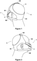
Figure 1 is a perspective view from the rear of a headgear in accordance with the present disclosure; -
Figure 2 is a perspective view from the rear and side of the headgear ofFigure 1 ; -
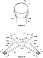
Figure 3 is a rear view of the headgear ofFigures 1 and 2 ; -
Figure 4 is a plan view of the exterior of the headgear ofFigures 1 to 3 when laid flat; -
Figure 5 is a plan view of the interior of the headgear ofFigures 1 to 4 when laid flat; -
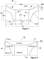
Figures 6 to 9 are plan views of a rear panel of the headgear ofFigures 1 to 5 , showing different dimensions and aspects of the rear panel; -
Figure 10 is a lay flat view of a continuous sheet of textile in an industry standard width of 59" (1498mm) with an example of the nesting patterns and yield that can be achieved with the rear panel ofFigures 6 to 9 ; -
Figure 11 is a hypothetical nesting pattern of two rear panels of headgear in accordance with the current disclosure; -
Figure 12 is an enlarged view corresponding toFigure 10 ; -
Figures 13 to 15 are lay flat views of a continuous sheet of textile in an industry standard width of 59" (1498mm) with an example of other nesting patterns and yield that can be achieved with the rear panel of headgear in accordance with the current disclosure; -
Figures 16 to 19 are plan views of a rear panel of headgear in accordance with the current disclosure showing different dimensions and aspects of the rear panel; -
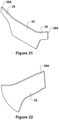
Figures 20 to 25 are plan views of another embodiment of a rear panel of the headgear ofFigures 1 to 5 , showing different dimensions and aspects of the rear panel withFigure 22 being an enlarged view of Area A ofFigure 24 ; and -
Figures 26 to 31 are plan views of a further embodiment of a rear panel of the headgear ofFigures 1 to 5 , showing different dimensions and aspects of the rear panel, withFigure 28 being an enlarged view of Area A of Figure 29j. - With reference initially to
Figures 1 to 3 , an embodiment of apatient interface assembly 1 comprising apatient interface 3 andheadgear 5 is illustrated on a user U, the patient interface in this example being a full face mask covering both the nose and mouth of the user U. Thepatient interface assembly 1 can be used in the field of respiratory therapy and therefore in any respiratory treatment, respiratory assistance, resuscitation or ventilation system. In some embodiments, theinterface assembly 1 has particular utility with forms of positive pressure respiratory therapy. For example, theinterface assembly 1 can be used for administering continuous positive airway pressure ("CPAP") treatments, variable positive airway pressure ("VPAP") treatments and/or bi-level positive airway pressure ("BiPAP") treatments. Theinterface assembly 1 can be compatible with one or more different types of suitable CPAP or non-invasive ventilation (NIV) systems. - The
patient interface 3 can comprise any of a plurality of different types of suitable mask configurations. For example, certain features, aspects and advantages of the present disclosure can be utilized with nasal masks, full face masks, oronasal masks, total face, or any other positive pressure mask. Although the illustrated mask is a full face mask, the scope of the present disclosure should not be limited by the particular embodiments described. - In the illustrated configuration, the
patient interface 3 comprises a mask body, optionally a mask frame and a connection port assembly. The mask body is configured to cover the user's mouth and/or nose to deliver respiratory gases to the user. The mask body can be secured to themask frame 5. Thepatient interface 3 is held in place on the user U by theheadgear 5 that wraps around a part or parts of the user's head. The connection port assembly can be connected to the mask body and/or mask frame, preferably with a releasable connection. In some configurations, the connection port assembly comprises an elbow connector configured to be connected between the mask body and/or mask frame and a gas delivery conduit (not shown). - The mask frame can couple to the mask body and help stabilize the
interface 3 on the user's face. The mask frame can be any shape and size to functionally secure theinterface 3 to the user's face. The mask frame can be attached to the mask body with interlocking clips, tabs or other functional couplers or may be permanently attached during the assembly process. In this latter case the mask body and mask frame are integral and configured to form a single component. The mask frame can be rigid, substantially rigid or semi-rigid to provide support for the mask body. For example, the mask frame can be at least partially made of a metal or rigid plastic, such as acrylic, polycarbonate or high-density polyethylene. - The mask frame can extend to the user's forehead and may optionally include a forehead rest. The forehead rest, if provided, can help stabilize the
interface 1 to the user's face by providing a support point for theinterface 1 and connection points for theheadgear 5. - If provided, the forehead rest can be a separate flexible piece that is attached or overmoulded onto the mask frame. For example, the forehead rest can be made of a flexible silicone that is overmoulded onto the frame bridge. The flexible material advantageously conforms to the user's forehead anatomy and helps improve comfort to the user with soft material contact. In some configurations, the forehead rest can be attached or integrally formed as part of the mask frame and can be made of the same material as the
mask frame 5 and frame bridge. - In this
example headgear 5 comprises a pair of upper side straps 5A extending from laterally spaced upper connections on the mask body or mask frame, a pair oflower side straps 5B extending from laterally spaced lower connections on the mask body or mask frame, arear panel 5C which joins the upper and lower side straps 5A, 5B, at the rear of the head of the user U, and acrown strap 5D which extends over the crown of the head of the user U, from eachupper side strap 5A. Suitable connectors, such as incorporating hook and loop fasteners, may be provided to secure theheadgear 5 to the mask body or mask frame. In this example, both pairs of upper andlower straps loop fasteners 6 at their respective strap ends, each strap being looped through the mask frame and/or forehead rest and back on itself. The amount by which eachstrap headgear 5. Both pairs of upper andlower straps gripping formations 8 at their distal ends. - Any or all of the
above straps 5A. 5B, 5C may include adjusters, such as buckles, configured to enable the length of the strap(s) to be adjusted. - Any one or more of the
straps 5A. 5B, 5C and/orrear panel 5C may be elastic or inelastic or comprise portions that are elastic or inelastic. Any one or more thestraps 5A. 5B, 5C orrear panel 5C may comprise more rigid portions, for example, to help maintain a desired shape of theheadgear 5. The materials, construction, and elasticity may vary betweenstraps 5A. 5B, 5C and/orrear panel 5C however, theheadgear 5 alternatively may be of uniform construction with the same material and elasticity used throughout the headgear. This may further reduce costs by enabling the entire assembly to be cut from sheets of the same material. - In this
example crown strap 5C comprises two crown strap portions 5DA, 5DB that are releasably connected together via the end of one crown strap portion 5DA being received in anaperture 21 of the other crown strap portion 5DB. The end of first crown strap portion 5DA is waisted such that there is anarrower width portion 23 spaced from the end of the first crown strap portion 5DA. Thewaisted portion 23 is substantially the same width as theaperture 21 and is located in theaperture 21 when the two crown strap portions 5DA, 5DB are connected together, with thewider end 24 of first crown strap portion 5DA protruding through the aperture and resisting removal of the first crown strap portion 5DA through theaperture 21. - With reference additionally to
Figures 4 and5 , the margins of therear panel 5C are shown, with thelower side straps 5B being joined to therear panel 5C at joins 25. The inner end of each crown strap portion 5DA, 5DB comprises a bifurcated region 27 forming twolegs respective legs 27A at joins 29 whilstlegs 27B are joined 30 to respective upper margins 31 of therear panel 5C. The joins may use any suitable joining means which can include any one or more of stitching, gluing, ultra-sonic welding, RF welding or any other form of seam welding. - The upper and lower side straps 5A, 5B are joined to the
rear panel 5C such that theupper straps 5A are non-parallel with thelower side straps 5B such that the distal ends of the upper and lower side straps 5A, 5B on each side of therear panel 5C are inclined toward one another. The angle between the upper and lower side straps 5A, 5B can be varied depending on the connection of the upper and lower side straps 5A, 5B to the patient interface. - Referring additionally to
Figure 6 , therear panel 5C can be considered to comprise a main portion orbody 33 and two opposed lateral portions orarms 35, with anotional transition line 34 between the main andlateral portions main portion 33 can be considered to be rectangular. The twolateral portions 35 each extend outwardly from the central plane or longitudinal axis XX and are inclined upwardly away from themain portion 33 and away from the longitudinal axis to facilitate connection with theupper straps 5A and locate thosestraps 5A in the correct position on the back of the user's head. - Each
upper strap 5A is connected entirely to a respective one of thelateral portions 35 of therear panel 5C in an upper corner region of therear panel 5C. Eachlower strap 5B is connected to a lower corner area of therear panel 5C, that includes at least a portion of thelateral portion 35 andmain portion 33. - The boundaries of the
main portion 33 are defined by a centrally located rectangle with upper and lower limits formed by the substantially straight parallel regions of the upper and lower margins of therear panel 5C and lateral limits formed by notionalvertical lines 34 the ends of which are located at points where the upper margin transitions from substantially horizontal by a line of best fit, to a curved line into thelateral portions 35. By 'substantially horizontal', we include that the upper margin is slightly curved. - Referring to
Figure 7 , example relative dimensions (mm) of therear panel 5C are: - The
main portion 33 is defined by a rectangle with dimensions of less than 100mm by 70mm, and in one example 77.9mm by 61.5mm. - The
lateral portions 35 are constrained within a rectangle of less than 60mm by 90mm, and in one example 56.6mm by 83.5 mm. - The entire
rear panel 5C is constrained within a rectangle R, shown in dashed line, of less than 200mm by 100mm, and in one example 191mm by 83.5mm. - The ratio of the area of each
lateral portion 35 to the area of themain portion 33 is between 0.8 and 0.9 and preferably 0.886. - Referring to
Figure 8 therear panel 5C can be effectively described with various example ratios relating thelateral portions 35 andmain portion 33. Example ratios are listed below. - The ratio of the width of a
lateral portion 35 to the width of themain portion 33 may be between 0.7 and 0.8, and in one example is 0.73. - The ratio of the height of a
lateral portion 35 to the height of themain portion 33 may be between 1.2 and 1.5, and in one example is 1.36. - The ratio of the width of the entire
rear panel 5C to the width of themain portion 33 may be between 2.0 and 3.0, and in one example is 2.45. - The ratio of the area of a
lateral portion 35 to the area of themain portion 33 is may be between 0.4 and 0.5, and in one example 0.443. - The ratio of the area of both
lateral portions 35 to the area of the entirerear panel 5C may be between 0.4 and 0.7, and in one example is 0.470. - The ratio of a cutout formed in the top of the
rear panel 5C defined by the area A between theupper margin 41 of therear panel 5C and a horizontal line 43 connecting the two most upper points 45 of thelateral portions 35 to the area of the entirerear panel 5C may be between 0.3 and 0.5, and in one example is 0.347. - The
rear panel 5C may be between 30 and 70%, and in one example makes up 56.64%, of a notional rectangular area A that extends to touch all extreme points of therear panel 5C. - The ratio of the width of the lower margin of the
rear panel 5C to the width of the entirerear panel 5C may be between 0.4 and 0.8, and in one example is 0.51. - Referring to
Figure 9 , example dimensions of, and example angles between, the different parts of therear panel 5C are shown. These include alateral portion 35 tip angle T which defines the angle of the straight,distal end margin 35A of eachlateral portion 35 relative to the horizontal base margin of themain portion 33. - Referring to
Figures 10 and12 , a continuous sheet oftextile 41 in an industry standard width of 59" (1498mm) is shown with an example of the nesting patterns and yield that can be achieved with arear panel 5C in accordance with this disclosure. It is desirable to firstly use an industry standard width of material, and to secondly maximise the amount of that material that is used, minimising the amount that is wasted and therefore reducing the overall manufacturing cost of the headgear assembly. - the shape and configuration of the
rear panel 5C is such that a relatively high yield is possible whenadjacent panels 5C are placed alongside each other with eachintermediate panel 5C in a given row ofrear panels 5C being inverted relative to theadjacent panel 5C. - In this position the angles and shape of the
lateral portions 35 are complimentary with each other which allows the lateral portions of each row to be positioned between the lateral portions of the adjacent rows without the rear panels contacting each other. This arrangement allows for a relatively high yield nesting pattern which decreases material waste and reduces the cost of the component due to the disused areas formed between rows of rear panels being inhabited partially/substantially by the adjacent rows of rear panels. - In this disclosure yields of over 75% are possible, and in this example a yield of 83.9% can be achieved.
- Referring to
Figure 11 , a hypothetical nesting pattern of tworear panels 5D that could achieve the maximum yield possible while leaving a clearance c of 1/8th of an inch between pieces to enable the die cutting blades to effectively operate is shown. This nesting pattern uses the following formula:
- The clearance c can be varied in order to achieve a satisfactory cut between adjacent
rear panels 5D. It is desirable from a material wastage point of view that this clearance is as small as possible. However, if the clearance equals zero, the quality of the cut margin of eachrear panel 5 may be compromised. -
Figures 13 to 15 show different examples of therear panel 5C where the tip angle T of the of thestraight end margin 35B of eachlateral portion 35 relative to thehorizontal base margin 33A of themain portion 33 is varied, this tip angle T affecting the yield. In each of these examples a yield of over 83% is achieved. Although the tip angle T will affect the available yield, this angle may also affect the aesthetics of the headgear, and/or the best angle to achieve a suitable joint with theupper side strap 5A. As such choosing the best tip angle T may require consideration of any one or more of these factors, and/or some compromise. - Referring to
Figures 16 to 18 , therear panel 5C is considered in an alternative manner as comprising a trapezoidalmain portion 33 with twolateral portions 35 each intersecting the trapezoidalmain portion 33. - Each
lateral portion 35 extends laterally outwardly, and is inclined, away frommain portion 33 and from the central vertical plane/longitudinal axis XX such that a longitudinal axis YY of eachlateral portion 35 is inclined relative to the longitudinal axis XX and relative to the straight, horizontal upper and lower margins of themain portion 33. - The
rear panel 5C may therefore be defined by a main portion orbody 33 comprising a substantially straight horizontallower base margin 33A leading to substantially straight, outwardlyinclined side margins 33B. Eachside margin 33B leads to a respectivelateral portion 35 comprising an elongate outwardly extending arm where the longitudinal axis YY of eacharm 35 is inclined relative to thebase margin 33A, and the angle of inclination of eacharm 35 relative to thebase margin 33A is less than the angle of inclination of theside margins 33B. Eachlateral arm 35 comprises substantially straight lower, end andupper margins end margin 35B being inclined relative to the central longitudinal axis XX of therear panel 5C. The lower andupper margins arm 35 leads into the substantially straightupper margin 33C of thepanel 5C, theupper margin 33C being parallel with thebase margin 33A. Thelower margin 35A of eacharm 35 leads into arespective side margin 33B of themain body 33. - When considered in this way:
- The
rear panel 5C is symmetrical about line XX. - The straight, horizontal upper and
lower margins main portion 33 are parallel. - The outwardly
inclined side margins 33B of themain portion 33, each extend from a separate lateral endpoint ofbase margin 33A at an angle of 70°, such thatside margins 33B extend upwardly and outwardly from the central plane XX. - The endpoints of
side margins 33B intersect the endpoints oftop margin 33C such thatbase margin 33A,side margins 33B andtop margin 33C together form a trapezoidal shape which is mirrored about plane XX withtop margin 33C >base margin 33A >side margins 33B. - The intersections of
side margins 33B withbase margin 33A are filleted with a 10mm radius. - The two
lateral portions 35 extend distally away from the central plane XX at an angle above horizontal. -
Lower arm margin 35A intersectsside margin 33B and extends distally away from the central plane XX at an angle of between 15 and 45°, and in one example of 26.1° from a plane parallel tobase margin 33A. - The intersection between
lower arm margin 35A andbase margin 33A is filleted with a 16mm radius. -
Upper line margin 35C intersectstop margin 33C and extends distally away from the central plane XX at an angle of between 15 and 45°, and in one example of 25.5°, fromtop margin 33C. - The intersection between
upper arm margin 35C andtop margin 33C is filleted, in this example with a 40mm radius. -
End arm margin 35B extends from the free end oflower arm margin 35A at an angle of between 0° and 20°, and in this example 5°, from a plane parallel to plane XX such - As illustrated in
Figure 19 : - The total area of the
rear panel 33 may be between 6000 and 13000mm2, and in this example is about 9,000mm2. - The ratio of the area of both
lateral portions 35 to themain portion 33 may be between 0.1 and 0.3, and in this example is about 0.185. - The ratio of the area of the
main portion 33 to the total area of therear panel 5C may be between 0.7 and 1.0, and in this example is about 0.815. - The
lateral portions 35 intersect themain portion 33 above the vertical midpoint of the main portion. - With the length of the
top edge margin 33C of themain portion 33 divided into two lateral thirds and a central third, eachlateral portion 35 can be said to intersect thetop edge margin 33C of themain portion 33 within the lateral third proximal to thelateral portion 35 in question. - In this disclosure the main portion or
body 33 is defined by the area captured within the top andbase margins side margins 33B, including the area defined where thetop margin 33C notionally extends towards the lateral portions orarms 35 and intersects with where theside margins 33B notionally extend towards to the lateral portions orarms 35. These notionally extending parts of the top andside margins Figure 19 for example. - The
headgear 5 may be configured such that the other dimensions and ratios set out above can vary in dependence upon the size of head gear 5 (andrear panel 5A) required. In other words, therear panel 5A may be configured to be scaled such that the proportions and ratios of various components will remain the same between the smallest to largest size of therear panel 5A. Thepanel 5A is configured to be scaleable such that for example the major dimensions of a large size may be 1.5 times bigger than the major dimensions of a small size. - Table 1 below shows example dimensions of three headgear sizes, for
headgear 5 in accordance with this disclosure. The headgearrear panel 5C described above is for a size Medium/Large. This is designed to fit a majority of a given set of users. The other two size options show examples of a largest practical rear panel size as well as a smallest practical rear panel size. However, the particular example dimensions listed in the table below are designed to be able to fit the largest and smallest head sizes of which we are aware, and illustrate that variations in proportions between different sizes is possible, i.e. this table lists possible extreme dimensions and as such these three size configurations are not scaled relative to one another as outlined above.Medium / L Rear Panel Dimensions (Adult Patient) Largest Practical Rear Panel Dimensions (Adult Patient) Smallest Practical Rear Panel Dimensions (Adult Patient) Overall Rear Panel Width 191mm 261mm 121mm Central Quadrilateral Region Width 77.9mm 150mm 10mm Overall Rear Panel Height 83.5mm 118.5mm 50mm - The
headgear 5 may provide a relatively low cost solution that is important for use in the NIV environment where masks and associated headgear are disposable and each patient receives a new mask every 14 days typically. The relatively low cost solution is achieved via a unique geometrical shape and configuration that allows relatively high yield manufacturing owing to the efficient nesting pattern. The relatively large single componentrear panel 5C may also increase patient comfort and/or improve the aesthetics of theheadgear 5, which may help to increase patient compliance. - The
headgear 5 may comprise part of a respiratory therapy system which comprises any one or more of: - a. a breathing gas flow generator;
- b. a breathing gas humidifier;
- c. a gas delivery conduit, which may or may not be heated;
- d. a patient interface.
- The
headgear 5 may comprise part of a patient interface assembly comprising the combination of theheadgear 5 and apatient interface 3. - The
headgear 5 may be manufactured from any suitable fabric material or combination of materials. Parts of theheadgear 5 may for example be manufactured from Breathoprene ®. - Referring to
Figures 20 to 25 , another embodiment ofrear panel 5C is shown, and will be referred to as rear panel 5C2. Panel 5C2 is closely similar toPanel 5C described above, and like features will be given like references. Only the differences are discussed below. - Rear panel 5C2 can again be considered to comprise a main portion or
body 33 and two opposed lateral portions orarms 35, with a notional transition line 37 between the main andlateral portions main portion 33 can be considered to be rectangular. The twolateral portions 35 each extend outwardly from the central plane or longitudinal axis XX and are inclined upwardly away from themain portion 33 and away from the longitudinal axis to facilitate connection with theupper straps 5A and locate thosestraps 5A in the correct position on the back of the user's head. Thelateral portions 35 of panel 5C2 terminate intips 35A of reduced width. These are configured to minimise laminate flare when welded to straps of the headgear. - Referring to
Figure 24 , the example relative dimensions (mm) of the rear panel 5C2 are identical or closely similar to that ofpanel 5C except that the tip of eachlateral arm 35 is approximately 2mm narrower, for the reason discussed above. The radius of curvature between the lower margin ofmain body 33 and eachlateral arm 35 is about 5mm in this example, as compared to about 10mm forpanel 5C. - Referring to
Figure 24 the rear panel 5C2 can be effectively described with the same example ratios relating thelateral portions 35 andmain portion 33, as described above forpanel 5C. Example ratios are listed below. - Referring to
Figure 25 , example dimensions of, and example angles between, the different parts of the rear panel 5C2 are shown. These are substantially the same as those ofpanel 5C. - Referring to
Figures 26 to 31 , another embodiment ofrear panel 5C is shown, and will be referred to as rear panel 5C3. Panel 5C3 is closely similar topanels 5C and 5C2 described at length above, and like features will be given like references. Panel 5C3 is a very similar height topanels 5C and 5C2, but is narrower overall, with a widermain portion 33, narrowerwidth lateral portions 35, andlateral portions 35 that are more steeply inclined relative to the horizontal (of the base margin of main portion 33). - Referring to
Figure 29 , example relative dimensions (mm) of the rear panel 5C3 are: - The
main portion 33 is defined by a rectangle with dimensions of less than 100mm by 70mm, and in one example 78.1mm by 63.9mm. - The
lateral portions 35 are constrained within a rectangle of less than 60mm by 90mm, and in one example 54.3mm by 83.2 mm. - The entire
rear panel 5C is constrained within a rectangle R, shown in dashed line, of less than 200mm by 100mm, and in one example 186.6mm by 83.2mm. - The ratio of the area of the
lateral portions 35 to the area of themain portion 33 is between 0.8 and 0.9 and preferably 0.92. - As with
rear panels 5C and 5C2, eachlateral portion 35 can be considered to comprise astem portion 35B which extends frommain body portion 33 and is defined between themain body portion 33 and a lower side margin comprising lower andupper parts lateral portion 35 further comprises a projectingportion 35F which projects radially outwardly from thestem portion 35B and is defined by theupper part 35E of lower side margin, thetip 35A, and anupper margin 35C. Each ofmargins upper part 35D of lower side margin and theupper margin 35C may be substantially parallel, or they may be inclined toward or away from one another, towardstip 35A. Thus the projectingportion 35F may taper or flare along its length, or be of substantially constant width. - In respect of panel 5C3, the
stem portion 35B is wider than that ofpanels 5C, 5C2, and is approximately 20% wider in this example. The lower part of eachlateral arm 35 is therefore more oblong thanpanels 5C, 5C2, and inclines upwardly away from the base margin ofmain portion 33 at a steeper angle such that the stem part of eachlateral arm 35 initially does not project outwardly as far asarms 35 ofpanels 5C, 5C2. Forpanels 5C, 5C2, the ratio of the width of eachlateral arm 35 to the width of themain body portion 33 is between 0.4:1 and 0.5:1. For panel 5C3, the ratio of the width of eachlateral arm 35 to the width of themain body portion 33 is between 0.6:1 and 0.8:1. These calculations are based on eachlateral arm 35 terminating where theupper arm margin 35F joins the straight, horizontal part of theupper margin 33C ofmain body portion 33. This termination point is defined by avertical plane 34 which extends through the intersection ofupper arm margin 35C with theupper margin 33C ofmain body portion 33, as can best be seen infigures 9 ,24 and29 . - Referring to
Figure 30 the rear panel 5C3 can be effectively described with various example ratios relating thelateral portions 35 andmain portion 33. Example ratios are listed below. - The ratio of the width of a
lateral portion 35 to the width of themain portion 33 may be between 0.7 and 0.8, and in one example is 0.69. - The ratio of the height of a
lateral portion 35 to the height of themain portion 33 may be between 1.2 and 1.5, and in one example is 1.30. - The ratio of the width of the entire rear panel 5C3 to the width of the
main portion 33 may be between 2.0 and 3.0, and in one example is 2.39. - The ratio of the area of a
lateral portion 35 to the area of themain portion 33 is may be between 0.4 and 0.5, and in one example is 0.46. - The ratio of the area of both
lateral portions 35 to the area of the entirerear panel 5C may be between 0.3 and 0.7, and in one example is 0.48. - The ratio of a cut-out formed in the top of the rear panel 5C3 defined by the area A between the
upper margin 41 of the rear panel 5C3 and a horizontal line 43 connecting the two most upper points 45 of thelateral portions 35 to the area of the entire rear panel 5C3 may be between 0.3 and 0.5, and in one example is 0.32. - The rear panel 5C3 may be between 30 and 70%, and in one example makes up 59.32%, of a notional rectangular area A that extends to touch all extreme points of the
rear panel 5C. - The ratio of the width of the lower margin of the rear panel 5C3 to the width of the entire rear panel 5C3 may be between 0.4 and 0.8, and in one example is 0.64.
- Referring to
Figure 31 , example dimensions of, and example angles between, the different parts of the rear panel 5C3 are shown. These include alateral portion 35 tip angle T which defines the angle of the straight,distal end margin 35A of eachlateral portion 35 relative to thehorizontal base margin 33A of themain portion 33. - The angle between the lower part of the lower side margin of each
lateral portion 35 and thebase margin 33A ofmain portion 33 may be between 50 and 90°, forpanel 5C and 5C2 is 70°, and for panel 5C3 is 82°. The lower part of the lower side margin is the part which extends from thebase margin 33A ofmain portion 33. The angle between theupper part 35D of lower side margin (and the longitudinal axis of the projecting arm portion) of eachlateral portion 35 and thebase margin 33A ofmain portion 33 may be between 25 and 70°, forpanel 5C is 45.5°, and for panel 5C3 is 32.4°. - The angle between the
upper side margin 35D of eachlateral portion 35 and thebase margin 33A ofmain portion 33 may be between 100 and 180°, forpanel 5C and 5C2 is 154.5°, and for panel 5C3 is 151.6°. Theupper side margin 35D is the part which extends from thetop margin 33C ofmain portion 33 to thetip 35A of eachlateral portion 35. - The end margin of the
tip 35A of eachlateral portion 35 is preferably substantially straight. The angle between the end margin of thetip 35A of eachlateral portion 35, and thebase margin 33A ofmain portion 33 is preferably between 80 and 120°, and forpanels 5C, 5C2 and 5C3 is 95°. - Unless the context clearly requires otherwise, throughout the description, the words "comprise", "comprising", and the like, are to be construed in an inclusive sense as opposed to an exclusive or exhaustive sense, that is to say, in the sense of "including, but not limited to".
- Although this disclosure has been described by way of example and with reference to possible embodiments thereof, it is to be understood that modifications or improvements may be made thereto without departing from the scope of the disclosure. The disclosure may also be said broadly to consist in the parts, elements and features referred to or indicated in the specification of the application, individually or collectively, in any or all combinations of two or more of said parts, elements or features. Furthermore, where reference has been made to specific components or integers of the disclosure having known equivalents, then such equivalents are herein incorporated as if individually set forth.
- Any discussion of the prior art throughout the specification should in no way be considered as an admission that such prior art is widely known or forms part of common general knowledge in the field.
- Set forth below are some embodiments of the foregoing disclosure:
- Embodiment 1: Headgear configured to be secured to a patient interface of a respiratory therapy system, to mount the patient interface on a user's head, the headgear comprising;
- at least one pair of side straps, each side strap having first and second opposed ends, a first end of each strap being secured to, or being configured to be secured to, the patient interface and to extend along the sides of the user's head;
- a rear panel configured to engage the rear of the user's head, the second end of each side strap being joined to the rear panel such that the or each pair of side straps extend from the rear panel; wherein
- the rear panel comprises a main body and a pair of laterally extending arms, the second end of each side strap being joined to a respective arm;
- the main body comprising:
- opposed top and base margins which are spaced apart by a distance,
- opposed side margins extending between the top and base margins, and
- a central longitudinal axis bisecting the top and base margins;
- each laterally extending arm being inclined relative to the central longitudinal axis, extending away from a respective side margin of the main body and comprising a distal arm end,
- each distal arm end having a width measured in a direction substantially parallel with the central longitudinal axis;
- wherein the width of each distal arm end is between 30% to 60% of the distance between the opposed top and base margins of the main body.
- Embodiment 2: The headgear of
embodiment 1, wherein the side margins of the main body of the rear panel are substantially parallel and substantially equal length such that the main body is substantially rectangular. - Embodiment 3: The headgear of
embodiment 1, wherein the side margins of the main body of the rear panel are substantially equal length and are inclined relative to the base margin such that the main body is substantially trapezoidal. - Embodiment 4: The headgear of any one of the preceding embodiments wherein two pairs of side straps are provided, one pair comprising upper side straps, the other pair comprising lower side straps.
- Embodiment 5: The headgear of any one of the preceding embodiments wherein each lateral arm is of substantially uniform width along its length.
- Embodiment 6: The headgear of any one of the preceding embodiments wherein the distal arm end comprises a substantially straight end margin.
- Embodiment 7: The headgear of
embodiment 6 wherein the end margin is parallel with the longitudinal axis. - Embodiment 8: The headgear or
embodiment 6 wherein the end margin is inclined relative to the longitudinal axis. - Embodiment 9: The headgear of
embodiment 8 wherein the end margin is inclined relative to the longitudinal axis at an angle between 0.1 and 20°. - Embodiment 10: The headgear of
embodiment 3 wherein the side margins of the rear panel are inclined relative to the longitudinal axis at a different angle to the angle of inclination of the lateral arms relative to the longitudinal axis. - Embodiment 11: The headgear of
embodiment 3 wherein the side margins of the rear panel are inclined at an angle between 0° and 40° relative to the longitudinal axis of the rear panel. - Embodiment 12: The headgear of any one of the preceding embodiments wherein the longitudinal axis of each arm is inclined at an angle between 40° and 90° relative to the longitudinal axis of the rear panel.
- Embodiment 13: The headgear of any one of the preceding embodiments wherein the entire rear panel is constrained within a notional rectangle of 100-300mm wide by 50-120 tall, and in some embodiments within a notional rectangle of 180-200mm by 75-95mm.
- Embodiment 14: The headgear of any one of the preceding embodiments when dependent on
embodiment 2 wherein the rear panel can be defined by any one or more of the following ratios:- a. the ratio of the length of a lateral arm to the length of the main portion is between 0.65 and 0.8, length being measured in a direction perpendicular to the longitudinal axis;
- b. the ratio of the height of a lateral arm to the height of the main portion, height being measured in a direction parallel to the longitudinal axis, is between 1.1 and 1.6;
- c. the ratio of the length of the entire rear panel to the length of the main portion is between 2.0 and 3.0;
- d. the ratio of the area of a lateral arm to the area of the main portion is between 0.3 and 0.5;
- e. the ratio of the area of both lateral arms to the area of the entire rear panel is between 0.3 and 0.7.
- f. the ratio of a cut out or recess formed adjacent the upper margin of the rear panel as defined by the area between the upper margin of the rear panel and a notional horizontal line extending between and connecting the two most upper points of the lateral arms, to the area of the entire rear panel is between 0.3 and 0.5.
- g. the rear panel comprises between 30 and 70% of a notional rectangular area that surrounds and contacts all extreme points of the rear panel.
- Embodiment 15: The headgear of any one of the preceding embodiments when dependent on
embodiment 3 wherein the rear panel can be defined by any one or more of the following ratios:- a. the total area of the rear panel is between 8000 and 13000mm2;
- b. the ratio of the area of both lateral arms to the area of the main portion of the rear panel is between 0.1 and 0.3.
- c. the ratio of the area of the main portion to the entire area of the main panel is between 0.75 and 1.0.
- Embodiment 16: The headgear of any one of the preceding embodiments where the rear panel is defined by the following formula; w2=1/2 d1 - 1/2 c;
where w2 = the width of the lateral arm as measured in a direction substantially parallel with the longitudinal axis, d1 = the distance between opposed top and base margins of the main portion, and c = the clearance between adjacent rear panels required during manufacture of multiple rear panels on a sheet of material to ensure a satisfactory quality of cut. - Embodiment 17: The headgear of
embodiment 3 wherein each inclined arm extends from a respective side margin and the top margin of the main body. - Embodiment 18: The headgear of
embodiment 3 wherein the main body of the rear panel comprises opposing top and base margins, opposing side margins connecting the opposing top and base margins, a central vertical plane connecting the mid points of the opposing top and base margins, and a central horizontal plane connecting the mid points of the opposing side margins,- wherein the opposing side margins are inclined relative to the opposing top and base margin, and are of equal length, such that the main body is substantially trapezoidal;
- wherein each inclined arm extends from one of the pair of side margins and the top margin of the trapezoidal shaped main body above the central horizontal plane and extend away from both the central horizontal and vertical planes, and at an angle between 0° and 90° from the horizontal plane.
- Embodiment 19: The headgear of
embodiment 3 wherein each angled arm extends away from one of the pair of side margins and the top margin of the trapezoidal shaped main body, and the area of each angled arm is less than 15% of the area of the main body. - Embodiment 20: The headgear of
embodiment 3 wherein each angled arm extends from one of the pair of side margins and the top margin of the main body, and each upper side strap connects entirely to a respective one of the pair of angled arms and the at least one of the pair of lower straps connects entirely to the main body. - Embodiment 21: The headgear of any one of the preceding embodiments wherein each laterally extending arm tapers along its length.
- Embodiment 22: The headgear of any one of
embodiments 1 to 20 wherein each laterally extending arm flares along its length. - Embodiment 23: The headgear of any one
embodiments 1 to 20 wherein each laterally extending arm is of substantially constant width along its length. - Embodiment 24: The headgear of any one of the preceding embodiments wherein the distal arm end of each laterally extending arm is stepped or tapered or waisted, so that the distal arm end is of narrower width than the remainder of the laterally extending arm.
- Embodiment 25: The headgear of any one of the preceding embodiments wherein the ratio of the width of each laterally extending arm to the width of the main body portion is between 0.4 and 0.8:1.
- Embodiment 26: Headgear configured to be secured to a patient interface of a respiratory therapy system, to mount the patient interface on a user's head, the headgear comprising;
- a rear panel configured to engage the rear of a user's head,
- a top strap extending from the rear panel and configured engage the crown of the user's head,
- a pair of upper side straps extending from the top strap, and
- a pair of lower side straps extending from the rear panel,
- the upper and lower side straps being secured to, or being configured to be secured to, the patient interface;
- the rear panel comprising a main body and a pair of inclined arms extending outwardly from the main body, wherein
- the main body comprises opposing top and base margins which are spaced apart by a distance, and opposing side margins connecting the opposing top and base margins, wherein
- the opposing side margins are inclined relative to the opposing top and base margin, and are of equal length, such that the main body is substantially trapezoidal;
- each inclined arm extending from a respective side margin and the top margin of the main body;
- the angled arms of the rear panel having a width which is between 30% to 60% the distance between the base and top margins of the main body.
- Embodiment 27: Headgear configured to be secured to a patient interface of a respiratory therapy system, to mount the patient interface on a user's head, the headgear comprising;
- a rear panel configured to engage the rear of a user's head;
- a pair of upper side straps extending from the rear panel, and
- a pair of lower side straps extending from the rear panel,
- the upper and lower side straps being secured to, or being configured to be secured, to the patient interface;
- the rear panel comprising a main body and a pair of opposed, laterally extending inclined arms, the main body comprising opposing top and base margins, opposing side margins connecting the opposing top and base margins, a central vertical plane connecting the mid points of the opposing top and base margins, and a central horizontal plane connecting the mid points of the opposing side margins,
- wherein the opposing side margins are inclined relative to the opposing top and base margins, and are of substantially equal length, such that the main body is substantially trapezoidal;
- wherein each inclined arm extends from a respective one of the pair of side margins and the top margin of the trapezoidal shaped main body, each inclined arm extending from a position above the central horizontal plane and away from both the central horizontal and vertical planes, and at an angle between 0° and 90° from the horizontal plane.
- Embodiment 28: Headgear configured to be secured to a patient interface of a respiratory therapy system, to mount the patient interface on a user's head, the headgear comprising:
- a rear panel configured to engage the rear of a user's head,
- a pair of upper side straps extending from the rear panel, and
- a pair of lower side straps extending from the rear panel,
- the upper and lower side straps being secured to, or being configured to be secured to, the patient interface;
- the rear panel comprising a main body and a pair of opposed, laterally extending inclined arms, the main body comprising opposing top and bottom margins and opposing side margins connecting the opposing top and bottom margins,
- wherein the opposing side margins are inclined relative to the opposing top and base margin, and are of substantially equal length, such that the main body is substantially trapezoidal;
- wherein each angled arm extends away from a respective one of the pair of side margins and the top margin of the trapezoidal shaped main body,
- wherein the area of each angled arm is less than 15% of the area of the main body.
- Embodiment 29: Headgear configured to be secured to a patient interface of a respiratory therapy system, to mount the patient interface on a user's head, the headgear comprising:
- a rear panel configured to engage the rear of a user's head,
- a pair of upper side straps extending from the rear panel, and
- a pair of lower side straps extending from the rear panel,
- the upper and lower side straps being secured to, or being configured to be secured to, the patient interface;
- the rear panel comprising a main body and a pair of opposed, laterally extending inclined arms, the main body comprising opposing top and bottom margins and opposing side margins connecting the opposing top and bottom margins,
- wherein the opposing side margins are inclined relative to the opposing top and base margin, and are of substantially equal length, such that the main body is substantially trapezoidal;
- each angled arm extends from a respective one of the pair of side margins and the top margin of the main body,
- wherein each upper side strap connects entirely to a respective one of the pair of angled arms, and each lower side strap connects entirely to the main body.
- Embodiment 30: A patient interface assembly comprising;
- a patient interface, and
- the headgear of any one of the previous embodiments.
- Embodiment 31: A respiratory therapy system comprising the headgear of any one of
embodiments 1 to 29 and any one or more of:- a. a breathing gas flow generator;
- b. a breathing gas humidifier;
- c. a gas delivery conduit, which may or may not be heated; and/or a patient interfaced.
- Embodiment 32: A method of manufacturing headgear of any one of
embodiments 1 to 29 comprising steps of:- a. controlling a die cutter to cut multiple rear panels from a single sheet of material, wherein the die cutter is controlled such that a first rear panel is cut in a first orientation on the sheet and such that an adjacent rear panel is cut in an inverted orientation on the sheet.
- Embodiment 33: The method of embodiment 32 wherein the yield is above 80%.
- Embodiment 34: A rear panel for a headgear, substantially as shown in
Figure 6 ,Figure 20 orFigure 26 . - Embodiment 35: A headgear, substantially as shown in
Figures 4 and5 .
Claims (15)
- Headgear (5) configured to be secured to a patient interface (3) of a respiratory therapy system, to mount the patient interface (3) on a user's head, the headgear (5) comprising:at least one pair of side straps (5A, 5B), each side strap having first and second opposed ends, a first end of each strap being secured to, or being configured to be secured to, the patient interface (3) and to extend along the sides of the user's head;a rear panel (5C, 5C2) configured to engage the rear of the user's head, the second end of each side strap (5A, 5B) being joined to the rear panel (5C, 5C2) such that the or each pair of side straps (5A, 5B) extend from the rear panel (5C, 5C2); whereinthe rear panel (5C, 5C2) comprises a main body (33) and a pair of laterally extending arms (35), the second end of each side strap being joined to a respective arm (35);the main body (33) comprising:opposed top and base margins (33C, 33A) which are spaced apart by a distance,substantially straight, outwardly inclined, opposed side margins (33B) extending between the top and base margins (33C, 33A), anda central longitudinal axis bisecting the top and base margins;each laterally extending arm (35) being inclined relative to the central longitudinal axis, extending away from a respective side margin (33B) of the main body (33) and comprising a distal arm end (35A), each distal arm end (35A) having a width measured in a direction substantially parallel with the central longitudinal axis; wherein the ratio of the area of both lateral extending arms (35) to the main body (33) may be between 0.1 and 0.3.
- The headgear (5) of claim 1, wherein the total area of the rear panel (5C, 5C2) is between 6000 and 13000mm2.
- The headgear (5) of claim 1 or claim 2, wherein the ratio of the area of the main body (33) to the total area of the rear panel (5C, 5C2) is between 0.7 and less than 1.0.
- The headgear (5) of any one of the preceding claims, wherein the laterally extending arms (35) intersect the main body (33) above a vertical midpoint of the main body (33).
- The headgear (5) of any one of the preceding claims, wherein when the length of the top margin (33C) of the main body (33) divided into two lateral thirds and a central third, each laterally extending arm (35) can be said to intersect the top margin (33C) of the main body (33) within the lateral third proximal to the laterally extending arm (35) in question.
- The headgear (5) of any one of the preceding claims, wherein the entire rear panel (5C, 52C) is constrained within a rectangle R of less than 200mm by 100mm.
- The headgear (5) of any one of the preceding claims, wherein the side margins (33B) of the main body (33) of the rear panel (5C, 52C) are substantially equal length and are inclined relative to the base margin (33A) such that the main (33) body is substantially trapezoidal.
- The headgear (5) of any one of the preceding claims, wherein two pairs of side straps (5A, 5B) are provided, one pair comprising upper side straps (5A), the other pair comprising lower side straps (5B).
- The headgear (5) of any one of the preceding claims, wherein the distal arm end (35A) comprises a substantially straight end margin, wherein the end margin is inclined relative to the longitudinal axis and wherein, preferably, the end margin is inclined relative to the longitudinal axis at an angle between 0.1 and 20°.
- The headgear (5) of any one of the preceding claims, wherein the side margins (33B) of the rear panel (33) are inclined relative to the longitudinal axis at a different angle to the angle of inclination of the laterally extending arms (35) relative to the longitudinal axis.
- The headgear (5) of any one of the preceding claims, wherein the side margins (33B) of the rear panel (33) are inclined at an angle between 0° and 40° relative to the longitudinal axis of the rear panel (33).
- The headgear (5) of any one of the preceding claims, wherein the longitudinal axis of each laterally extending arm (35) is inclined at an angle between 40° and 90° relative to the longitudinal axis of the rear panel (5C, 52C).
- The headgear (5) of any one of the preceding claims, wherein each laterally extending arm (35) extends from a respective side margin (33B) and the top margin (33A) of the main body (33).
- The headgear (5) of any one of the preceding claims, wherein the distal arm end (35A) of each laterally extending arm (35) is stepped or tapered or waisted, so that the distal arm end (35A) is of narrower width than the remainder of the laterally extending arm (35).
- A patient interface assembly comprising;a patient interface (3), andthe headgear (5) of any one of the preceding claims.
Applications Claiming Priority (3)
| Application Number | Priority Date | Filing Date | Title |
|---|---|---|---|
| US201862657427P | 2018-04-13 | 2018-04-13 | |
| EP19785042.3A EP3773845B1 (en) | 2018-04-13 | 2019-04-12 | Headgear for use with a patient interface of a respiratory therapy system |
| PCT/NZ2019/050037 WO2019199180A1 (en) | 2018-04-13 | 2019-04-12 | Headgear for use with a patient interface of a respiratory therapy system |
Related Parent Applications (2)
| Application Number | Title | Priority Date | Filing Date |
|---|---|---|---|
| EP19785042.3A Division EP3773845B1 (en) | 2018-04-13 | 2019-04-12 | Headgear for use with a patient interface of a respiratory therapy system |
| EP19785042.3A Division-Into EP3773845B1 (en) | 2018-04-13 | 2019-04-12 | Headgear for use with a patient interface of a respiratory therapy system |
Publications (3)
| Publication Number | Publication Date |
|---|---|
| EP4420703A2 true EP4420703A2 (en) | 2024-08-28 |
| EP4420703A3 EP4420703A3 (en) | 2024-11-06 |
| EP4420703B1 EP4420703B1 (en) | 2025-12-31 |
Family
ID=68163725
Family Applications (2)
| Application Number | Title | Priority Date | Filing Date |
|---|---|---|---|
| EP24165464.9A Active EP4420703B1 (en) | 2018-04-13 | 2019-04-12 | Head cover for use with a patient interface of a respiratory therapy system |
| EP19785042.3A Active EP3773845B1 (en) | 2018-04-13 | 2019-04-12 | Headgear for use with a patient interface of a respiratory therapy system |
Family Applications After (1)
| Application Number | Title | Priority Date | Filing Date |
|---|---|---|---|
| EP19785042.3A Active EP3773845B1 (en) | 2018-04-13 | 2019-04-12 | Headgear for use with a patient interface of a respiratory therapy system |
Country Status (5)
| Country | Link |
|---|---|
| US (1) | US20210030991A1 (en) |
| EP (2) | EP4420703B1 (en) |
| AU (2) | AU2019250645B2 (en) |
| SG (1) | SG11202009955QA (en) |
| WO (1) | WO2019199180A1 (en) |
Families Citing this family (3)
| Publication number | Priority date | Publication date | Assignee | Title |
|---|---|---|---|---|
| USD1061868S1 (en) * | 2019-10-16 | 2025-02-11 | Fisher & Paykel Healthcare Limited | Headgear |
| USD1137639S1 (en) * | 2023-11-10 | 2026-07-28 | Dcstar Inc | Strap |
| CN117839025A (en) * | 2023-12-07 | 2024-04-09 | 北京怡和嘉业医疗科技股份有限公司 | Headband assembly and mask system |
Family Cites Families (27)
| Publication number | Priority date | Publication date | Assignee | Title |
|---|---|---|---|---|
| CA1302009C (en) * | 1988-07-08 | 1992-06-02 | Brian H. Harrison | Universal head harness |
| DE20122944U1 (en) * | 2000-12-12 | 2011-05-12 | ResMed Ltd., Bella Vista | headband |
| NZ712109A (en) * | 2002-11-08 | 2017-03-31 | Resmed Ltd | Headgear assembly for a respiratory mask assembly |
| JP4695600B2 (en) * | 2003-11-11 | 2011-06-08 | エムアーペー・メディツィーン−テヒノロギー・ゲゼルシャフト・ミット・ベシュレンクテル・ハフツング | Headband means for a respiratory mask and method of manufacturing the headband means |
| WO2006000046A1 (en) * | 2004-06-25 | 2006-01-05 | Resmed Limited | Forehead support for a patient interface |
| US9492627B2 (en) * | 2005-01-03 | 2016-11-15 | Resmed Limited | Headgear assembly for patient interface |
| CN104645476B (en) * | 2005-06-06 | 2017-08-22 | 瑞思迈有限公司 | Mask system |
| WO2007006089A1 (en) * | 2005-07-08 | 2007-01-18 | Resmed Limited | Headgear for mask assembly |
| US7878200B2 (en) * | 2006-02-13 | 2011-02-01 | Carefusion 2200, Inc. | Infant headgear for supporting a patient airway interface device |
| US20110072553A1 (en) * | 2006-09-07 | 2011-03-31 | Peter Chi Fai Ho | Headgear Assembly |
| DE102007050369B4 (en) * | 2006-10-24 | 2025-08-21 | Löwenstein Medical Technology S.A. | Banded holding device for ventilation masks |
| NZ615814A (en) * | 2007-07-30 | 2015-05-29 | Resmed Ltd | Patient interface |
| NZ592064A (en) * | 2008-12-10 | 2014-05-30 | Resmed Ltd | Headgear for masks |
| LT3117861T (en) * | 2011-04-15 | 2021-09-10 | Fisher&Paykel Healthcare Limited | INTERFACE INCLUDING A ROTATABLE PART OF THE NOSE BRIDGE |
| AU2012300184A1 (en) * | 2011-08-22 | 2013-10-03 | Resmed Limited | Ultrasonic welding of fabrics for sleep apnea treatment |
| NZ714593A (en) * | 2013-04-12 | 2017-08-25 | Resmed Ltd | Neck strap, crown strap assembly and headgear for a breathing mask |
| SG11201508589QA (en) * | 2013-04-26 | 2015-11-27 | Fisher & Paykel Healthcare Ltd | Headgear for breathing mask |
| EP4368228B1 (en) * | 2013-07-17 | 2025-08-27 | ResMed Pty Ltd | A patient interface system for treatment of respiratory disorders |
| CN204319466U (en) * | 2013-09-30 | 2015-05-13 | 中山谷能医疗器械科技有限公司 | A kind of main bandage forming the three-dimensional head bandage of breathing mask |
| AU2014334947B2 (en) * | 2013-10-18 | 2019-06-27 | Fisher & Paykel Healthcare Limited | Headgear |
| EP4397470A3 (en) * | 2013-12-11 | 2024-08-14 | Fisher & Paykel Healthcare Limited | Respiratory interface |
| US11160945B2 (en) * | 2014-03-31 | 2021-11-02 | Fisher & Paykel Healthcare Limited | Headgear for respiratory interfaces |
| WO2016075658A1 (en) * | 2014-11-14 | 2016-05-19 | Fisher & Paykel Healthcare Limited | Patient interface |
| US20160287829A1 (en) * | 2015-03-31 | 2016-10-06 | Tom Whitehead | Cushioned Sleep Apnea Mask |
| EP4215236B1 (en) * | 2015-07-31 | 2025-03-19 | Fisher & Paykel Healthcare Limited | Headgear for a respiratory mask |
| CN109414559B (en) * | 2016-06-29 | 2021-11-16 | 皇家飞利浦有限公司 | Method of generating a configuration for a customized head-mounted device |
| CA3036634A1 (en) * | 2016-10-05 | 2018-04-12 | Fisher & Paykel Healthcare Limited | Patient interfaces |
-
2019
- 2019-04-12 WO PCT/NZ2019/050037 patent/WO2019199180A1/en not_active Ceased
- 2019-04-12 US US17/046,152 patent/US20210030991A1/en active Pending
- 2019-04-12 SG SG11202009955QA patent/SG11202009955QA/en unknown
- 2019-04-12 AU AU2019250645A patent/AU2019250645B2/en active Active
- 2019-04-12 EP EP24165464.9A patent/EP4420703B1/en active Active
- 2019-04-12 EP EP19785042.3A patent/EP3773845B1/en active Active
-
2024
- 2024-12-12 AU AU2024278332A patent/AU2024278332A1/en active Pending
Also Published As
| Publication number | Publication date |
|---|---|
| EP3773845A1 (en) | 2021-02-17 |
| EP4420703B1 (en) | 2025-12-31 |
| US20210030991A1 (en) | 2021-02-04 |
| AU2019250645B2 (en) | 2025-01-09 |
| EP3773845B1 (en) | 2024-07-03 |
| WO2019199180A1 (en) | 2019-10-17 |
| SG11202009955QA (en) | 2020-11-27 |
| AU2024278332A1 (en) | 2025-01-09 |
| EP4420703A3 (en) | 2024-11-06 |
| EP3773845A4 (en) | 2022-01-19 |
| AU2019250645A1 (en) | 2020-10-15 |
Similar Documents
| Publication | Publication Date | Title |
|---|---|---|
| AU2022204190B2 (en) | Breathing apparatus | |
| JP7150792B2 (en) | Respirator neck straps, crown strap assemblies and headgear | |
| AU2024278332A1 (en) | Headgear for use with a patient interface of a respiratory therapy system | |
| US6805117B1 (en) | Universal fitting headgear | |
| US7779832B1 (en) | Headgear for use with a patient interface device | |
| EP1957170B1 (en) | Infant nasal interface prong device | |
| JP2022023884A (en) | Frame and headgear for respiratory mask system | |
| JP2023099569A (en) | Frame and headgear for respirator assembly | |
| AU2023201038B2 (en) | Patient interface | |
| EP4364775B1 (en) | PATIENT INTERFACE ARRANGEMENT WITH NASAL PROBE | |
| US20040065330A1 (en) | Dynamic infant nasal CPAP system and method | |
| US20080121234A1 (en) | Patient Interface with Variable Footprint | |
| EP2308536A1 (en) | Headgear | |
| EP2550050A1 (en) | Patent interface device employing a floating adjustment arm | |
| WO2021059216A1 (en) | Nasal cannula and securement system | |
| EP2727620B1 (en) | Adjusting component used for breathing mask and breathing mask | |
| CN120187479A (en) | Patient interface cushions | |
| AU2011231176A1 (en) | Patent interface device employing a floating adjustment arm |
Legal Events
| Date | Code | Title | Description |
|---|---|---|---|
| PUAI | Public reference made under article 153(3) epc to a published international application that has entered the european phase |
Free format text: ORIGINAL CODE: 0009012 |
|
| STAA | Information on the status of an ep patent application or granted ep patent |
Free format text: STATUS: THE APPLICATION HAS BEEN PUBLISHED |
|
| AC | Divisional application: reference to earlier application |
Ref document number: 3773845 Country of ref document: EP Kind code of ref document: P |
|
| AK | Designated contracting states |
Kind code of ref document: A2 Designated state(s): AL AT BE BG CH CY CZ DE DK EE ES FI FR GB GR HR HU IE IS IT LI LT LU LV MC MK MT NL NO PL PT RO RS SE SI SK SM TR |
|
| PUAL | Search report despatched |
Free format text: ORIGINAL CODE: 0009013 |
|
| AK | Designated contracting states |
Kind code of ref document: A3 Designated state(s): AL AT BE BG CH CY CZ DE DK EE ES FI FR GB GR HR HU IE IS IT LI LT LU LV MC MK MT NL NO PL PT RO RS SE SI SK SM TR |
|
| RIC1 | Information provided on ipc code assigned before grant |
Ipc: A61M 16/06 20060101AFI20241002BHEP |
|
| STAA | Information on the status of an ep patent application or granted ep patent |
Free format text: STATUS: REQUEST FOR EXAMINATION WAS MADE |
|
| 17P | Request for examination filed |
Effective date: 20250428 |
|
| GRAP | Despatch of communication of intention to grant a patent |
Free format text: ORIGINAL CODE: EPIDOSNIGR1 |
|
| STAA | Information on the status of an ep patent application or granted ep patent |
Free format text: STATUS: GRANT OF PATENT IS INTENDED |
|
| INTG | Intention to grant announced |
Effective date: 20250924 |
|
| GRAS | Grant fee paid |
Free format text: ORIGINAL CODE: EPIDOSNIGR3 |
|
| GRAA | (expected) grant |
Free format text: ORIGINAL CODE: 0009210 |
|
| STAA | Information on the status of an ep patent application or granted ep patent |
Free format text: STATUS: THE PATENT HAS BEEN GRANTED |
|
| AC | Divisional application: reference to earlier application |
Ref document number: 3773845 Country of ref document: EP Kind code of ref document: P |
|
| AK | Designated contracting states |
Kind code of ref document: B1 Designated state(s): AL AT BE BG CH CY CZ DE DK EE ES FI FR GB GR HR HU IE IS IT LI LT LU LV MC MK MT NL NO PL PT RO RS SE SI SK SM TR |
|
| REG | Reference to a national code |
Ref country code: CH Ref legal event code: F10 Free format text: ST27 STATUS EVENT CODE: U-0-0-F10-F00 (AS PROVIDED BY THE NATIONAL OFFICE) Effective date: 20251231 Ref country code: GB Ref legal event code: FG4D |
|
| REG | Reference to a national code |
Ref country code: DE Ref legal event code: R096 Ref document number: 602019080033 Country of ref document: DE |
|
| REG | Reference to a national code |
Ref country code: IE Ref legal event code: FG4D |
|
| P01 | Opt-out of the competence of the unified patent court (upc) registered |
Free format text: CASE NUMBER: UPC_APP_0008361_4420703/2026 Effective date: 20260302 |
|
| PGFP | Annual fee paid to national office [announced via postgrant information from national office to epo] |
Ref country code: GB Payment date: 20260319 Year of fee payment: 8 |
|
| REG | Reference to a national code |
Ref country code: LT Ref legal event code: MG9D |
|
| PG25 | Lapsed in a contracting state [announced via postgrant information from national office to epo] |
Ref country code: NO Free format text: LAPSE BECAUSE OF FAILURE TO SUBMIT A TRANSLATION OF THE DESCRIPTION OR TO PAY THE FEE WITHIN THE PRESCRIBED TIME-LIMIT Effective date: 20260331 |
|
| PG25 | Lapsed in a contracting state [announced via postgrant information from national office to epo] |
Ref country code: HR Free format text: LAPSE BECAUSE OF FAILURE TO SUBMIT A TRANSLATION OF THE DESCRIPTION OR TO PAY THE FEE WITHIN THE PRESCRIBED TIME-LIMIT Effective date: 20251231 Ref country code: FI Free format text: LAPSE BECAUSE OF FAILURE TO SUBMIT A TRANSLATION OF THE DESCRIPTION OR TO PAY THE FEE WITHIN THE PRESCRIBED TIME-LIMIT Effective date: 20251231 |
|
| PGFP | Annual fee paid to national office [announced via postgrant information from national office to epo] |
Ref country code: IT Payment date: 20260319 Year of fee payment: 8 |
|
| PG25 | Lapsed in a contracting state [announced via postgrant information from national office to epo] |
Ref country code: RS Free format text: LAPSE BECAUSE OF FAILURE TO SUBMIT A TRANSLATION OF THE DESCRIPTION OR TO PAY THE FEE WITHIN THE PRESCRIBED TIME-LIMIT Effective date: 20260331 |
|
| PGFP | Annual fee paid to national office [announced via postgrant information from national office to epo] |
Ref country code: FR Payment date: 20260320 Year of fee payment: 8 |
|
| PG25 | Lapsed in a contracting state [announced via postgrant information from national office to epo] |
Ref country code: LV Free format text: LAPSE BECAUSE OF FAILURE TO SUBMIT A TRANSLATION OF THE DESCRIPTION OR TO PAY THE FEE WITHIN THE PRESCRIBED TIME-LIMIT Effective date: 20251231 |
|
| PG25 | Lapsed in a contracting state [announced via postgrant information from national office to epo] |
Ref country code: BG Free format text: LAPSE BECAUSE OF FAILURE TO SUBMIT A TRANSLATION OF THE DESCRIPTION OR TO PAY THE FEE WITHIN THE PRESCRIBED TIME-LIMIT Effective date: 20251231 |
|
| REG | Reference to a national code |
Ref country code: NL Ref legal event code: MP Effective date: 20251231 |
|
| REG | Reference to a national code |
Ref country code: AT Ref legal event code: MK05 Ref document number: 1872539 Country of ref document: AT Kind code of ref document: T Effective date: 20251231 |
|
| PG25 | Lapsed in a contracting state [announced via postgrant information from national office to epo] |
Ref country code: NL Free format text: LAPSE BECAUSE OF FAILURE TO SUBMIT A TRANSLATION OF THE DESCRIPTION OR TO PAY THE FEE WITHIN THE PRESCRIBED TIME-LIMIT Effective date: 20251231 |
|
| PG25 | Lapsed in a contracting state [announced via postgrant information from national office to epo] |
Ref country code: LT Free format text: LAPSE BECAUSE OF FAILURE TO SUBMIT A TRANSLATION OF THE DESCRIPTION OR TO PAY THE FEE WITHIN THE PRESCRIBED TIME-LIMIT Effective date: 20251231 |
|
| PG25 | Lapsed in a contracting state [announced via postgrant information from national office to epo] |
Ref country code: SM Free format text: LAPSE BECAUSE OF FAILURE TO SUBMIT A TRANSLATION OF THE DESCRIPTION OR TO PAY THE FEE WITHIN THE PRESCRIBED TIME-LIMIT Effective date: 20251231 |
|
| PG25 | Lapsed in a contracting state [announced via postgrant information from national office to epo] |
Ref country code: ES Free format text: LAPSE BECAUSE OF FAILURE TO SUBMIT A TRANSLATION OF THE DESCRIPTION OR TO PAY THE FEE WITHIN THE PRESCRIBED TIME-LIMIT Effective date: 20251231 |
|
| PG25 | Lapsed in a contracting state [announced via postgrant information from national office to epo] |
Ref country code: PL Free format text: LAPSE BECAUSE OF FAILURE TO SUBMIT A TRANSLATION OF THE DESCRIPTION OR TO PAY THE FEE WITHIN THE PRESCRIBED TIME-LIMIT Effective date: 20251231 |
|
| PGFP | Annual fee paid to national office [announced via postgrant information from national office to epo] |
Ref country code: DE Payment date: 20260319 Year of fee payment: 8 |
|
| PG25 | Lapsed in a contracting state [announced via postgrant information from national office to epo] |
Ref country code: AT Free format text: LAPSE BECAUSE OF FAILURE TO SUBMIT A TRANSLATION OF THE DESCRIPTION OR TO PAY THE FEE WITHIN THE PRESCRIBED TIME-LIMIT Effective date: 20251231 |
|
| PG25 | Lapsed in a contracting state [announced via postgrant information from national office to epo] |
Ref country code: EE Free format text: LAPSE BECAUSE OF FAILURE TO SUBMIT A TRANSLATION OF THE DESCRIPTION OR TO PAY THE FEE WITHIN THE PRESCRIBED TIME-LIMIT Effective date: 20251231 |
|
| PG25 | Lapsed in a contracting state [announced via postgrant information from national office to epo] |
Ref country code: PT Free format text: LAPSE BECAUSE OF FAILURE TO SUBMIT A TRANSLATION OF THE DESCRIPTION OR TO PAY THE FEE WITHIN THE PRESCRIBED TIME-LIMIT Effective date: 20260430 Ref country code: IS Free format text: LAPSE BECAUSE OF FAILURE TO SUBMIT A TRANSLATION OF THE DESCRIPTION OR TO PAY THE FEE WITHIN THE PRESCRIBED TIME-LIMIT Effective date: 20260430 |
|
| PG25 | Lapsed in a contracting state [announced via postgrant information from national office to epo] |
Ref country code: CZ Free format text: LAPSE BECAUSE OF FAILURE TO SUBMIT A TRANSLATION OF THE DESCRIPTION OR TO PAY THE FEE WITHIN THE PRESCRIBED TIME-LIMIT Effective date: 20251231 |
|
| PG25 | Lapsed in a contracting state [announced via postgrant information from national office to epo] |
Ref country code: SK Free format text: LAPSE BECAUSE OF FAILURE TO SUBMIT A TRANSLATION OF THE DESCRIPTION OR TO PAY THE FEE WITHIN THE PRESCRIBED TIME-LIMIT Effective date: 20251231 |
|
| PG25 | Lapsed in a contracting state [announced via postgrant information from national office to epo] |
Ref country code: SE Free format text: LAPSE BECAUSE OF FAILURE TO SUBMIT A TRANSLATION OF THE DESCRIPTION OR TO PAY THE FEE WITHIN THE PRESCRIBED TIME-LIMIT Effective date: 20251231 |