EP4420695A1 - Auto-injector with motor body and cassette body - Google Patents
Auto-injector with motor body and cassette body Download PDFInfo
- Publication number
- EP4420695A1 EP4420695A1 EP23158590.2A EP23158590A EP4420695A1 EP 4420695 A1 EP4420695 A1 EP 4420695A1 EP 23158590 A EP23158590 A EP 23158590A EP 4420695 A1 EP4420695 A1 EP 4420695A1
- Authority
- EP
- European Patent Office
- Prior art keywords
- drug delivery
- motor body
- delivery device
- contact surface
- cassette body
- Prior art date
- Legal status (The legal status is an assumption and is not a legal conclusion. Google has not performed a legal analysis and makes no representation as to the accuracy of the status listed.)
- Pending
Links
- 229940090047 auto-injector Drugs 0.000 title description 3
- 238000012377 drug delivery Methods 0.000 claims abstract description 43
- 230000003993 interaction Effects 0.000 claims description 5
- 238000002347 injection Methods 0.000 description 7
- 239000007924 injection Substances 0.000 description 7
- 239000003814 drug Substances 0.000 description 4
- 238000012986 modification Methods 0.000 description 4
- 230000004048 modification Effects 0.000 description 4
- 238000003780 insertion Methods 0.000 description 3
- 230000037431 insertion Effects 0.000 description 3
- 230000000295 complement effect Effects 0.000 description 2
- 239000007788 liquid Substances 0.000 description 2
- 238000004519 manufacturing process Methods 0.000 description 2
- 230000007246 mechanism Effects 0.000 description 2
- 238000002360 preparation method Methods 0.000 description 2
- 230000001225 therapeutic effect Effects 0.000 description 2
- 230000002411 adverse Effects 0.000 description 1
- 230000006835 compression Effects 0.000 description 1
- 238000007906 compression Methods 0.000 description 1
- 229940079593 drug Drugs 0.000 description 1
- 238000001746 injection moulding Methods 0.000 description 1
- 238000000034 method Methods 0.000 description 1
- 229940071643 prefilled syringe Drugs 0.000 description 1
- 238000003825 pressing Methods 0.000 description 1
- 239000000243 solution Substances 0.000 description 1
- 238000003860 storage Methods 0.000 description 1
- 230000001960 triggered effect Effects 0.000 description 1
Images





Classifications
-
- A—HUMAN NECESSITIES
- A61—MEDICAL OR VETERINARY SCIENCE; HYGIENE
- A61M—DEVICES FOR INTRODUCING MEDIA INTO, OR ONTO, THE BODY; DEVICES FOR TRANSDUCING BODY MEDIA OR FOR TAKING MEDIA FROM THE BODY; DEVICES FOR PRODUCING OR ENDING SLEEP OR STUPOR
- A61M5/00—Devices for bringing media into the body in a subcutaneous, intra-vascular or intramuscular way; Accessories therefor, e.g. filling or cleaning devices, arm-rests
- A61M5/178—Syringes
- A61M5/20—Automatic syringes, e.g. with automatically actuated piston rod, with automatic needle injection, filling automatically
-
- A—HUMAN NECESSITIES
- A61—MEDICAL OR VETERINARY SCIENCE; HYGIENE
- A61M—DEVICES FOR INTRODUCING MEDIA INTO, OR ONTO, THE BODY; DEVICES FOR TRANSDUCING BODY MEDIA OR FOR TAKING MEDIA FROM THE BODY; DEVICES FOR PRODUCING OR ENDING SLEEP OR STUPOR
- A61M5/00—Devices for bringing media into the body in a subcutaneous, intra-vascular or intramuscular way; Accessories therefor, e.g. filling or cleaning devices, arm-rests
- A61M5/178—Syringes
- A61M5/24—Ampoule syringes, i.e. syringes with needle for use in combination with replaceable ampoules or carpules, e.g. automatic
-
- A—HUMAN NECESSITIES
- A61—MEDICAL OR VETERINARY SCIENCE; HYGIENE
- A61M—DEVICES FOR INTRODUCING MEDIA INTO, OR ONTO, THE BODY; DEVICES FOR TRANSDUCING BODY MEDIA OR FOR TAKING MEDIA FROM THE BODY; DEVICES FOR PRODUCING OR ENDING SLEEP OR STUPOR
- A61M5/00—Devices for bringing media into the body in a subcutaneous, intra-vascular or intramuscular way; Accessories therefor, e.g. filling or cleaning devices, arm-rests
- A61M5/002—Packages specially adapted therefor, e.g. for syringes or needles, kits for diabetics
-
- A—HUMAN NECESSITIES
- A61—MEDICAL OR VETERINARY SCIENCE; HYGIENE
- A61M—DEVICES FOR INTRODUCING MEDIA INTO, OR ONTO, THE BODY; DEVICES FOR TRANSDUCING BODY MEDIA OR FOR TAKING MEDIA FROM THE BODY; DEVICES FOR PRODUCING OR ENDING SLEEP OR STUPOR
- A61M5/00—Devices for bringing media into the body in a subcutaneous, intra-vascular or intramuscular way; Accessories therefor, e.g. filling or cleaning devices, arm-rests
- A61M5/178—Syringes
- A61M5/24—Ampoule syringes, i.e. syringes with needle for use in combination with replaceable ampoules or carpules, e.g. automatic
- A61M5/2422—Ampoule syringes, i.e. syringes with needle for use in combination with replaceable ampoules or carpules, e.g. automatic using emptying means to expel or eject media, e.g. pistons, deformation of the ampoule, or telescoping of the ampoule
-
- A—HUMAN NECESSITIES
- A61—MEDICAL OR VETERINARY SCIENCE; HYGIENE
- A61M—DEVICES FOR INTRODUCING MEDIA INTO, OR ONTO, THE BODY; DEVICES FOR TRANSDUCING BODY MEDIA OR FOR TAKING MEDIA FROM THE BODY; DEVICES FOR PRODUCING OR ENDING SLEEP OR STUPOR
- A61M5/00—Devices for bringing media into the body in a subcutaneous, intra-vascular or intramuscular way; Accessories therefor, e.g. filling or cleaning devices, arm-rests
- A61M5/178—Syringes
- A61M5/28—Syringe ampoules or carpules, i.e. ampoules or carpules provided with a needle
- A61M5/281—Syringe ampoules or carpules, i.e. ampoules or carpules provided with a needle using emptying means to expel or eject media, e.g. pistons, deformation of the ampoule, or telescoping of the ampoule
-
- A—HUMAN NECESSITIES
- A61—MEDICAL OR VETERINARY SCIENCE; HYGIENE
- A61M—DEVICES FOR INTRODUCING MEDIA INTO, OR ONTO, THE BODY; DEVICES FOR TRANSDUCING BODY MEDIA OR FOR TAKING MEDIA FROM THE BODY; DEVICES FOR PRODUCING OR ENDING SLEEP OR STUPOR
- A61M5/00—Devices for bringing media into the body in a subcutaneous, intra-vascular or intramuscular way; Accessories therefor, e.g. filling or cleaning devices, arm-rests
- A61M5/178—Syringes
- A61M5/31—Details
-
- A—HUMAN NECESSITIES
- A61—MEDICAL OR VETERINARY SCIENCE; HYGIENE
- A61M—DEVICES FOR INTRODUCING MEDIA INTO, OR ONTO, THE BODY; DEVICES FOR TRANSDUCING BODY MEDIA OR FOR TAKING MEDIA FROM THE BODY; DEVICES FOR PRODUCING OR ENDING SLEEP OR STUPOR
- A61M5/00—Devices for bringing media into the body in a subcutaneous, intra-vascular or intramuscular way; Accessories therefor, e.g. filling or cleaning devices, arm-rests
- A61M5/178—Syringes
- A61M5/31—Details
- A61M5/315—Pistons; Piston-rods; Guiding, blocking or restricting the movement of the rod or piston; Appliances on the rod for facilitating dosing ; Dosing mechanisms
-
- A—HUMAN NECESSITIES
- A61—MEDICAL OR VETERINARY SCIENCE; HYGIENE
- A61M—DEVICES FOR INTRODUCING MEDIA INTO, OR ONTO, THE BODY; DEVICES FOR TRANSDUCING BODY MEDIA OR FOR TAKING MEDIA FROM THE BODY; DEVICES FOR PRODUCING OR ENDING SLEEP OR STUPOR
- A61M5/00—Devices for bringing media into the body in a subcutaneous, intra-vascular or intramuscular way; Accessories therefor, e.g. filling or cleaning devices, arm-rests
- A61M5/178—Syringes
- A61M5/31—Details
- A61M5/315—Pistons; Piston-rods; Guiding, blocking or restricting the movement of the rod or piston; Appliances on the rod for facilitating dosing ; Dosing mechanisms
- A61M5/31511—Piston or piston-rod constructions, e.g. connection of piston with piston-rod
-
- A—HUMAN NECESSITIES
- A61—MEDICAL OR VETERINARY SCIENCE; HYGIENE
- A61M—DEVICES FOR INTRODUCING MEDIA INTO, OR ONTO, THE BODY; DEVICES FOR TRANSDUCING BODY MEDIA OR FOR TAKING MEDIA FROM THE BODY; DEVICES FOR PRODUCING OR ENDING SLEEP OR STUPOR
- A61M5/00—Devices for bringing media into the body in a subcutaneous, intra-vascular or intramuscular way; Accessories therefor, e.g. filling or cleaning devices, arm-rests
- A61M5/178—Syringes
- A61M5/31—Details
- A61M5/315—Pistons; Piston-rods; Guiding, blocking or restricting the movement of the rod or piston; Appliances on the rod for facilitating dosing ; Dosing mechanisms
- A61M5/31565—Administration mechanisms, i.e. constructional features, modes of administering a dose
- A61M5/31576—Constructional features or modes of drive mechanisms for piston rods
-
- A—HUMAN NECESSITIES
- A61—MEDICAL OR VETERINARY SCIENCE; HYGIENE
- A61M—DEVICES FOR INTRODUCING MEDIA INTO, OR ONTO, THE BODY; DEVICES FOR TRANSDUCING BODY MEDIA OR FOR TAKING MEDIA FROM THE BODY; DEVICES FOR PRODUCING OR ENDING SLEEP OR STUPOR
- A61M5/00—Devices for bringing media into the body in a subcutaneous, intra-vascular or intramuscular way; Accessories therefor, e.g. filling or cleaning devices, arm-rests
- A61M5/178—Syringes
- A61M5/31—Details
- A61M5/315—Pistons; Piston-rods; Guiding, blocking or restricting the movement of the rod or piston; Appliances on the rod for facilitating dosing ; Dosing mechanisms
- A61M5/31565—Administration mechanisms, i.e. constructional features, modes of administering a dose
- A61M5/31576—Constructional features or modes of drive mechanisms for piston rods
- A61M5/31578—Constructional features or modes of drive mechanisms for piston rods based on axial translation, i.e. components directly operatively associated and axially moved with plunger rod
- A61M5/3158—Constructional features or modes of drive mechanisms for piston rods based on axial translation, i.e. components directly operatively associated and axially moved with plunger rod performed by axially moving actuator operated by user, e.g. an injection button
-
- A—HUMAN NECESSITIES
- A61—MEDICAL OR VETERINARY SCIENCE; HYGIENE
- A61M—DEVICES FOR INTRODUCING MEDIA INTO, OR ONTO, THE BODY; DEVICES FOR TRANSDUCING BODY MEDIA OR FOR TAKING MEDIA FROM THE BODY; DEVICES FOR PRODUCING OR ENDING SLEEP OR STUPOR
- A61M5/00—Devices for bringing media into the body in a subcutaneous, intra-vascular or intramuscular way; Accessories therefor, e.g. filling or cleaning devices, arm-rests
- A61M5/178—Syringes
- A61M5/31—Details
- A61M5/32—Needles; Details of needles pertaining to their connection with syringe or hub; Accessories for bringing the needle into, or holding the needle on, the body; Devices for protection of needles
- A61M5/3202—Devices for protection of the needle before use, e.g. caps
-
- A—HUMAN NECESSITIES
- A61—MEDICAL OR VETERINARY SCIENCE; HYGIENE
- A61M—DEVICES FOR INTRODUCING MEDIA INTO, OR ONTO, THE BODY; DEVICES FOR TRANSDUCING BODY MEDIA OR FOR TAKING MEDIA FROM THE BODY; DEVICES FOR PRODUCING OR ENDING SLEEP OR STUPOR
- A61M5/00—Devices for bringing media into the body in a subcutaneous, intra-vascular or intramuscular way; Accessories therefor, e.g. filling or cleaning devices, arm-rests
- A61M5/178—Syringes
- A61M5/31—Details
- A61M5/32—Needles; Details of needles pertaining to their connection with syringe or hub; Accessories for bringing the needle into, or holding the needle on, the body; Devices for protection of needles
- A61M5/3202—Devices for protection of the needle before use, e.g. caps
- A61M5/3204—Needle cap remover, i.e. devices to dislodge protection cover from needle or needle hub, e.g. deshielding devices
-
- A—HUMAN NECESSITIES
- A61—MEDICAL OR VETERINARY SCIENCE; HYGIENE
- A61M—DEVICES FOR INTRODUCING MEDIA INTO, OR ONTO, THE BODY; DEVICES FOR TRANSDUCING BODY MEDIA OR FOR TAKING MEDIA FROM THE BODY; DEVICES FOR PRODUCING OR ENDING SLEEP OR STUPOR
- A61M5/00—Devices for bringing media into the body in a subcutaneous, intra-vascular or intramuscular way; Accessories therefor, e.g. filling or cleaning devices, arm-rests
- A61M5/178—Syringes
- A61M5/31—Details
- A61M5/32—Needles; Details of needles pertaining to their connection with syringe or hub; Accessories for bringing the needle into, or holding the needle on, the body; Devices for protection of needles
- A61M5/3205—Apparatus for removing or disposing of used needles or syringes, e.g. containers; Means for protection against accidental injuries from used needles
- A61M5/321—Means for protection against accidental injuries by used needles
- A61M5/3213—Caps placed axially onto the needle, e.g. equipped with finger protection guards
-
- A—HUMAN NECESSITIES
- A61—MEDICAL OR VETERINARY SCIENCE; HYGIENE
- A61M—DEVICES FOR INTRODUCING MEDIA INTO, OR ONTO, THE BODY; DEVICES FOR TRANSDUCING BODY MEDIA OR FOR TAKING MEDIA FROM THE BODY; DEVICES FOR PRODUCING OR ENDING SLEEP OR STUPOR
- A61M5/00—Devices for bringing media into the body in a subcutaneous, intra-vascular or intramuscular way; Accessories therefor, e.g. filling or cleaning devices, arm-rests
- A61M5/178—Syringes
- A61M5/20—Automatic syringes, e.g. with automatically actuated piston rod, with automatic needle injection, filling automatically
- A61M2005/206—With automatic needle insertion
-
- A—HUMAN NECESSITIES
- A61—MEDICAL OR VETERINARY SCIENCE; HYGIENE
- A61M—DEVICES FOR INTRODUCING MEDIA INTO, OR ONTO, THE BODY; DEVICES FOR TRANSDUCING BODY MEDIA OR FOR TAKING MEDIA FROM THE BODY; DEVICES FOR PRODUCING OR ENDING SLEEP OR STUPOR
- A61M5/00—Devices for bringing media into the body in a subcutaneous, intra-vascular or intramuscular way; Accessories therefor, e.g. filling or cleaning devices, arm-rests
- A61M5/178—Syringes
- A61M5/20—Automatic syringes, e.g. with automatically actuated piston rod, with automatic needle injection, filling automatically
- A61M2005/2073—Automatic syringes, e.g. with automatically actuated piston rod, with automatic needle injection, filling automatically preventing premature release, e.g. by making use of a safety lock
- A61M2005/208—Release is possible only when device is pushed against the skin, e.g. using a trigger which is blocked or inactive when the device is not pushed against the skin
-
- A—HUMAN NECESSITIES
- A61—MEDICAL OR VETERINARY SCIENCE; HYGIENE
- A61M—DEVICES FOR INTRODUCING MEDIA INTO, OR ONTO, THE BODY; DEVICES FOR TRANSDUCING BODY MEDIA OR FOR TAKING MEDIA FROM THE BODY; DEVICES FOR PRODUCING OR ENDING SLEEP OR STUPOR
- A61M5/00—Devices for bringing media into the body in a subcutaneous, intra-vascular or intramuscular way; Accessories therefor, e.g. filling or cleaning devices, arm-rests
- A61M5/178—Syringes
- A61M5/24—Ampoule syringes, i.e. syringes with needle for use in combination with replaceable ampoules or carpules, e.g. automatic
- A61M2005/2433—Ampoule fixed to ampoule holder
-
- A—HUMAN NECESSITIES
- A61—MEDICAL OR VETERINARY SCIENCE; HYGIENE
- A61M—DEVICES FOR INTRODUCING MEDIA INTO, OR ONTO, THE BODY; DEVICES FOR TRANSDUCING BODY MEDIA OR FOR TAKING MEDIA FROM THE BODY; DEVICES FOR PRODUCING OR ENDING SLEEP OR STUPOR
- A61M5/00—Devices for bringing media into the body in a subcutaneous, intra-vascular or intramuscular way; Accessories therefor, e.g. filling or cleaning devices, arm-rests
- A61M5/178—Syringes
- A61M5/24—Ampoule syringes, i.e. syringes with needle for use in combination with replaceable ampoules or carpules, e.g. automatic
- A61M2005/2485—Ampoule holder connected to rest of syringe
- A61M2005/2492—Ampoule holder connected to rest of syringe via snap connection
-
- A—HUMAN NECESSITIES
- A61—MEDICAL OR VETERINARY SCIENCE; HYGIENE
- A61M—DEVICES FOR INTRODUCING MEDIA INTO, OR ONTO, THE BODY; DEVICES FOR TRANSDUCING BODY MEDIA OR FOR TAKING MEDIA FROM THE BODY; DEVICES FOR PRODUCING OR ENDING SLEEP OR STUPOR
- A61M5/00—Devices for bringing media into the body in a subcutaneous, intra-vascular or intramuscular way; Accessories therefor, e.g. filling or cleaning devices, arm-rests
- A61M5/178—Syringes
- A61M5/31—Details
- A61M5/315—Pistons; Piston-rods; Guiding, blocking or restricting the movement of the rod or piston; Appliances on the rod for facilitating dosing ; Dosing mechanisms
- A61M5/31565—Administration mechanisms, i.e. constructional features, modes of administering a dose
- A61M5/31576—Constructional features or modes of drive mechanisms for piston rods
- A61M2005/31588—Constructional features or modes of drive mechanisms for piston rods electrically driven
-
- A—HUMAN NECESSITIES
- A61—MEDICAL OR VETERINARY SCIENCE; HYGIENE
- A61M—DEVICES FOR INTRODUCING MEDIA INTO, OR ONTO, THE BODY; DEVICES FOR TRANSDUCING BODY MEDIA OR FOR TAKING MEDIA FROM THE BODY; DEVICES FOR PRODUCING OR ENDING SLEEP OR STUPOR
- A61M2205/00—General characteristics of the apparatus
- A61M2205/33—Controlling, regulating or measuring
- A61M2205/3331—Pressure; Flow
-
- A—HUMAN NECESSITIES
- A61—MEDICAL OR VETERINARY SCIENCE; HYGIENE
- A61M—DEVICES FOR INTRODUCING MEDIA INTO, OR ONTO, THE BODY; DEVICES FOR TRANSDUCING BODY MEDIA OR FOR TAKING MEDIA FROM THE BODY; DEVICES FOR PRODUCING OR ENDING SLEEP OR STUPOR
- A61M2205/00—General characteristics of the apparatus
- A61M2205/33—Controlling, regulating or measuring
- A61M2205/3379—Masses, volumes, levels of fluids in reservoirs, flow rates
-
- A—HUMAN NECESSITIES
- A61—MEDICAL OR VETERINARY SCIENCE; HYGIENE
- A61M—DEVICES FOR INTRODUCING MEDIA INTO, OR ONTO, THE BODY; DEVICES FOR TRANSDUCING BODY MEDIA OR FOR TAKING MEDIA FROM THE BODY; DEVICES FOR PRODUCING OR ENDING SLEEP OR STUPOR
- A61M2205/00—General characteristics of the apparatus
- A61M2205/82—Internal energy supply devices
Definitions
- the present disclosure relates generally to a drug delivery device and, more specifically, to an auto-injector.
- Various types of automatic injection devices have been developed to allow drug solutions and other liquid therapeutic preparations to be administered by untrained personnel or to be self-injected.
- these devices include a reservoir that is pre-filled with the liquid therapeutic preparation, and some type of automatic needle-injection mechanism that can be triggered by the user.
- Many of these devices such as auto-injectors, are designed so that the reservoir, such as a pre-filled syringe, is assembled into the device during assembly of the device.
- many drug delivery devices In addition to automatically deploying the needle-injection mechanism, many drug delivery devices also automatically shield the needle after use of the device to prevent any unintended contact with the needle.
- Automatic injection devices include several interacting components that must slide and/or rotate relative to one another in order to effectively perform an injection.
- the relatively small tolerances necessary to achieve component fitment can be difficult to achieve with an injection molding process depending on the shape of the individual components. Poor fitment can lead to increased friction between components, sticking or jamming of components, and increased wear, all of which can adversely affect drug delivery. As such, there is an ongoing need in the art to optimize the fitment of components of drug delivery devices.
- a drug delivery device including an upper housing shell, a lower housing shell, and a syringe.
- the syringe includes a barrel, a stopper, and a needle, at least a portion of the syringe positioned within the lower housing shell.
- the drug delivery device further includes a drive assembly including a plunger body configured to move the stopper within the barrel upon actuation of the drive assembly, a cassette body configured to receive the syringe, and a motor body configured to engage the cassette body.
- the motor body includes a pair of sidewalls and a contact surface provided on each of the pair of sidewalls. The contact surface engages a corresponding contact surface of the cassette body.
- the contact surface of the motor body includes a planar, substantially vertical surface.
- the corresponding contact surface of the cassette body includes a planar, substantially vertical surface.
- the contact surface of the motor body continuously contacts the corresponding contact surface of the cassette body contact along a length of the contact surface of the motor body.
- the cassette body includes at least one motor body rib including the contact surface of the cassette body.
- the contact surface of the cassette body extends substantially the entire length of the at least one motor body rib.
- the at least contact surface of the motor body is provided on an inside face of the sidewall of the motor body.
- the motor body includes at least one protrusion configured to engage a corresponding wall surface of the cassette body.
- the cassette body includes a pair of sidewalls including the corresponding wall surface.
- the protrusion includes a curved outer surface.
- interaction of the at least one protrusion and the corresponding wall surface of the cassette body forces the contact surface of the motor body into engagement with the contact surface of the cassette body.
- contact between the at least one protrusion and the corresponding wall surface of the cassette body defines a predetermined distance between inside faces of the sidewalls of the motor body.
- contact between the at least one protrusion and the corresponding wall surface of the cassette body forces the sidewalls of the motor body parallel to one another.
- the at least one protrusion and the contact surface of the motor body is provided on opposite sides of the sidewall of the motor body.
- the at least one protrusion is provided on an outside face of the sidewall of the motor body.
- any numerical range recited herein is intended to include all values and sub-ranges subsumed therein.
- a range of " 1 to 10" is intended to include all sub-ranges between (and including) the recited minimum value of 1 and the recited maximum value of 10, that is, having a minimum value equal to or greater than 1 and a maximum value of equal to or less than 10.
- distal refers to a portion of said component nearest to a patient.
- proximal refers to a portion of said component farthest from the patient.
- the term "at least one of” is synonymous with "one or more of'.
- the phrase "at least one of A, B, and C” means any one of A, B, and C, or any combination of any two or more of A, B, and C.
- "at least one of A, B, and C” includes one or more of A alone; or one or more of B alone; or one or more of C alone; or one or more of A and one or more of B; or one or more of A and one or more of C; or one or more of B and one or more of C; or one or more of all of A, B, and C.
- the term "at least two of' is synonymous with "two or more of'.
- the phrase "at least two of D, E, and F” means any combination of any two or more of D, E, and F.
- “at least two of D, E, and F” includes one or more of D and one or more of E; or one or more of D and one or more of F; or one or more of E and one or more of F; or one or more of all of D, E, and F.
- the drug delivery device 100 includes a first subassembly 110, a second subassembly 140, and a syringe 116.
- the first subassembly 110 may include a lower housing shell 112, a cap 114, a syringe holder 118, a needle cover 124, and a cassette body 128.
- the second subassembly 140 may include a drive assembly including a plunger body 150.
- the plunger body 150 includes a plunger rod 152 and a spring guide member 154 including a drive member 156 and a drive opening 158.
- the second subassembly 140 may further include a motor body 159, a lever actuation member 130, and an upper housing shell 142.
- the syringe 116 may be received by the syringe holder 118 and includes a barrel 117, a stopper 122, a needle 120, and a rigid needle shield (RNS) 126.
- RNS rigid needle shield
- the lower housing shell 112, the cassette body 128, and the upper housing shell 142 generally form a housing for receiving the various components of the drug delivery device 100, although other suitable housing arrangements may be utilized.
- the first subassembly 110 and the second subassembly 140 may be secured to each other during assembly by a locking clip, although other suitable arrangements may be utilized.
- the upper housing shell 142 includes an outer lip 143 configured to fit around an inner lip 113 of the lower housing shell 112 when the device 100 is assembled.
- the drug delivery device 100 may be an auto-injector, although the features described herein may be incorporated into other suitable drug delivery devices.
- the drive member 156 may be a compression spring received within a drive opening 158 defined by the plunger body 150, although other suitable drive members may be utilized, including, but not limited to, compressed gas, an electric motor, hydraulic pressure, other types of springs, etc.
- the drive member 156 engages the plunger body 150 and the motor body 159 and biases the plunger body 150 in a direction extending from the second subassembly 140 toward the first subassembly 110.
- the plunger body 150 defines a lever opening that receives the lever actuation member 130 and defines the rotation axis of the lever actuation member 130.
- the lever actuation member 130 prevents movement of the plunger body 150 when the lever actuation member 130 is in the locked position through engagement of the lever actuation member 130 with the motor body 159.
- the lever actuation member 130 Upon rotation of the lever actuation member 130 from the locked position to the released position, the lever actuation member 130 is disengaged from the motor body 159 thereby allowing the drive member 156 to move the plunger body 150 and the plunger rod 152 toward the first subassembly 110.
- the plunger rod 152 and the drive member 156 are spaced from and parallel to each other and extend in a longitudinal direction of the device 100.
- the spring guide member 154 is secured to the upper housing shell 142 and received within the drive opening 158 of the plunger body 150.
- the drive member 156 is received by the spring guide member 154 such that the drive member 156 is positioned between the plunger body 150 and the spring guide member 154.
- the drive assembly may also include a plunger rod cover (not shown) that receives the plunger rod 152 of the plunger body 150.
- the plunger rod cover may be configured to guide insertion of the plunger rod 152 into the barrel 117 of the syringe 116 and engage the stopper 122 to dispense the medicament from the barrel 117 of the syringe 116.
- the drug delivery device 100 is configured to automatically deliver a dose of medicament from the syringe 116 to a patient upon actuation of the device 100. More specifically, upon actuation of the drug delivery device 100, the drive assembly is configured to engage the stopper 122 of the syringe 116, displace the syringe 116 such that the needle 120 pierces the skin of the patient, and displace the stopper 122 within the barrel 117 of the syringe 116 to deliver the medicament within the barrel 117.
- the drug delivery device 100 includes a storage position, a pre-use position, an actuation position, an injection position, and a post-use position, as described in International Patent Application Publication Nos. WO 2020/173991 , WO 2020/173992 , WO 2020/173993 , WO 2020/173994 , and WO 2020/173995 .
- the needle cover 124 is configured to shield the needle 120 of the syringe 116 from the patient when the device 100 is in the pre-use and the post-use positions.
- the needle cover 124 is moveable between a pre-use position, an actuation position, and a post-use positon, with a spring 125 biasing the needle cover 124 towards the pre-use position and the post-use position.
- the spring 125 may be positioned between the needle cover 124 and the syringe holder 118, although other suitable arrangements may be utilized.
- the lever actuation member 130 is moveable between a locked position where movement of the drive assembly is prevented and a released position where movement of the drive assembly is allowed. More specifically, the lever actuation member 130 is rotatable about a rotation axis between the locked position and the released position. When the lever actuation member 130 is in the locked position, the lever actuation member 130 is engaged with the motor body 159 and the drive assembly to prevent movement of the drive assembly.
- lever actuation member 130 When the lever actuation member 130 is in the released position, which may be achieved by pressing the needle cover 124 onto the patient's skin at the site of injection, shifting the needle cover proximally into the lower housing shell 112, the lever actuation member 130 is disengaged from the motor body 159 thereby allowing movement of the drive assembly toward the syringe 116.
- the rotation axis of the lever actuation member 130 extends perpendicular to a longitudinal axis of the device 100, although other suitable arrangements may be utilized.
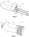
- FIGS. 3 and 4 illustrate the second subassembly 140 and the first subassembly 110, respectively, as these subassemblies may be provided for final assembly of the device 100.
- a safety pin 200 is inserted through apertures 164 (see FIG. 6 ) of the motor body 159.
- the apertures 164 are located in proximity to a distal end of the plunger body 150 so that with the safety pin 200 inserted through the apertures 164, the safety pin 200 prevents rotation of the lever actuation member 130 and unintentional actuation of the drive member 156.
- the safety pin 200 is removed prior to or during final assembly of the device 100.
- the motor body 159 is generally U-shaped and includes a pair of opposing sidewalls 326 configured to receive the plunger body 150 therebetween.
- the motor body 159 defines the safety pin apertures 164 extending transversely through the sidewalls 326 to facilitate insertion of the safety pin 200 (see FIG. 3 ).
- the motor body 159 further includes at least one cassette clip 328 extending from the respective sidewalls 326 for engaging complementary openings 330 (see FIG. 9 ) defined by the cassette body 128. Engagement of the at least one cassette clip 328 with the openings 330 secures the motor body 159 to the cassette body 128, which is discussed in more detail below.
- the at least one cassette clip 328 includes an angled face 332 and a planar face 334, which are configured to allow insertion of the at least one cassette clip 328 into the corresponding openings 330 of the cassette body 128, but prevent easy removal of the cassette clips 328 once inserted into the openings 330 of the cassette body 128.
- the motor body 159 is configured to be inserted in the upper housing shell 142 of the second subassembly 140.
- the motor body 159 includes at least one shell stop 360 extending outward from the opposing sidewalls 326 of the motor body 159.
- Each shell stop 360 has a planar proximal face 362 configured to engage an internal structure of the upper housing shell 142 to index the motor body 159 in the upper housing shell 142.
- the at least one shell stop 360 extends a sufficient distance outward from the sidewalls 326 of motor body 159 so that the at least one shell stop 360 remains at least partially engaged with the corresponding internal structure of the upper housing shell 142 when the sidewalls 326 of the motor body 159 are deflected inward during connection of the motor body 159 to the cassette body 128.
- each of the at least one shell stops 360 includes a cantilevered end 364.
- Each of the sidewalls 326 of the motor body 159 includes a contact surface 160 for engaging with the cassette body 128.
- the contact surface 160 is configured to slide along a corresponding contact surface 180 (see FIGS. 10-11 ) of the cassette body 128.
- the contact surfaces 160 of the motor body 159 are provided on inside faces of the sidewalls 326 in the illustrated embodiment, but in other embodiments the contact surfaces 160 may be provided on the outside of the sidewalls 326 with corresponding modifications made to the cassette body 128.
- the contact surfaces 160 of the motor body 159 may be planar, substantially vertical surfaces, though other profiles are within the scope of the present disclosure.
- the contact surfaces 160 of the motor body 159 may be configured for continuous contact with the corresponding contact surfaces 180 of the cassette body 128 along the length of the contact surfaces 160, 180. In some embodiments, the contact surfaces 160, 180 may be configured for intermittent contact along the length of the contact surfaces 160, 180. In non-limiting embodiments, contact surface 180 has a slope that provides for ease of assembly of first subassembly 110 and second subassembly 140.
- the motor body 159 includes at least one protrusion 162 configured to maintain sliding contact between the contact surface 160 of the motor body 159 and the corresponding contact surface 180 of the cassette body 128.
- the protrusion 162 may be located and sized so as to engage a corresponding wall surface 182 (see FIG. 9-10 ) of the cassette body 128, which in turn forces the contact surface 160 of the motor body 159 into contact with the corresponding contact surface 180 of the cassette body 128.
- lateral slop between the contact surfaces 160 of the motor body 159 and the contact surfaces 180 of the cassette body 128 is eliminated.
- the contact surfaces 160 and protrusions 162 interact with the cassette body 128 to hold the motor body 159 in the intended shape to ensure smooth assembly and operation of the device 100.
- the at least one protrusion 162 may include a single protrusion or multiple protrusions provided at intervals along the length of the sidewall 326.
- the at least one protrusion 162 may include a curved outer surface, as shown in the accompanying drawings, but other profiles are within the scope of the present disclosure.
- the cassette body 128 is generally U-shaped and configured to fit within the lower housing shell 112 and receive the syringe 116 and various other components as described herein in connection with FIGS. 1-4 .
- the cassette body 128 includes opposing sidewalls 170, the inside of which may include the wall surface 182 to which the protrusions 162 of the motor body 159 engage.
- the cassette body 128 further includes the openings 330 that receive the corresponding cassette clips 328 (see FIG. 6 ) of the motor body 159 when the device 100 is assembled.
- the cassette body 128 includes a needle cover clip 364 that engage the needle cover 124 to restrict the axial movement of the needle cover 124 relative to the cassette body 128.
- the cassette body 128 further includes motor body ribs 368 and upper housing shell ribs 370, which are configured to engage corresponding portions of the motor body 159 and the lower housing shell 112, respectively, to aid in the assembly of the device 100.
- the motor body ribs 368 may include the contact surfaces 180 configured to engage the corresponding contact surfaces 160 of the motor body 159.
- the contact surfaces 180 may have a complementary profile to the corresponding contact surfaces 160 of the motor body 159.
- the contact surfaces 180 may be substantially planar, vertical surfaces as shown in the accompanying drawings.
- the contact surfaces 180 extend substantially the entire length of the motor body ribs 368.
- the cassette body 128 also includes syringe holder stops 372, which are configured to engage portions of the syringe holder 118 to limit the axial movement of the syringe holder 118 relative to the cassette body 128.
- FIG. 12 a cross section of the device is illustrated to show the interaction between the cassette body 128 and the motor body 159.
- Each of the protrusions 162 of the motor body 159 engages the corresponding wall surface 182 of the cassette body 128.
- the interaction of the protrusions 162 and the wall surfaces 182 forces the contact surfaces 160 of the motor body 159 into engagement with the contact surfaces 180 of the cassette body 128, thereby defining a predetermined distance D between inside faces of the sidewalls 326 of the motor body 159.
- interaction of the protrusions 162 and the wall surfaces 182 forces the sidewalls 326 of the motor body 159 parallel to one another.
Landscapes
- Health & Medical Sciences (AREA)
- Engineering & Computer Science (AREA)
- Heart & Thoracic Surgery (AREA)
- Vascular Medicine (AREA)
- Anesthesiology (AREA)
- Biomedical Technology (AREA)
- Hematology (AREA)
- Life Sciences & Earth Sciences (AREA)
- Animal Behavior & Ethology (AREA)
- General Health & Medical Sciences (AREA)
- Public Health (AREA)
- Veterinary Medicine (AREA)
- Diabetes (AREA)
- Environmental & Geological Engineering (AREA)
- Infusion, Injection, And Reservoir Apparatuses (AREA)
Abstract
A drug delivery device includes an upper housing shell, a lower housing shell, and a syringe. The syringe includes a barrel, a stopper, and a needle, at least a portion of the syringe positioned within the lower housing shell. The drug delivery device further includes a drive assembly including a plunger body configured to move the stopper within the barrel upon actuation of the drive assembly, a cassette body configured to receive the syringe, and a motor body configured to engage the cassette body. The motor body includes a pair of sidewalls and a contact surface provided on each of the pair of sidewalls. The contact surface engages a corresponding contact surface of the cassette body.
Description
- The present disclosure relates generally to a drug delivery device and, more specifically, to an auto-injector.
- Various types of automatic injection devices have been developed to allow drug solutions and other liquid therapeutic preparations to be administered by untrained personnel or to be self-injected. Generally, these devices include a reservoir that is pre-filled with the liquid therapeutic preparation, and some type of automatic needle-injection mechanism that can be triggered by the user. Many of these devices, such as auto-injectors, are designed so that the reservoir, such as a pre-filled syringe, is assembled into the device during assembly of the device. In addition to automatically deploying the needle-injection mechanism, many drug delivery devices also automatically shield the needle after use of the device to prevent any unintended contact with the needle.
- Automatic injection devices include several interacting components that must slide and/or rotate relative to one another in order to effectively perform an injection. The relatively small tolerances necessary to achieve component fitment can be difficult to achieve with an injection molding process depending on the shape of the individual components. Poor fitment can lead to increased friction between components, sticking or jamming of components, and increased wear, all of which can adversely affect drug delivery. As such, there is an ongoing need in the art to optimize the fitment of components of drug delivery devices.
- Provided herein is a drug delivery device including an upper housing shell, a lower housing shell, and a syringe. The syringe includes a barrel, a stopper, and a needle, at least a portion of the syringe positioned within the lower housing shell. The drug delivery device further includes a drive assembly including a plunger body configured to move the stopper within the barrel upon actuation of the drive assembly, a cassette body configured to receive the syringe, and a motor body configured to engage the cassette body. The motor body includes a pair of sidewalls and a contact surface provided on each of the pair of sidewalls. The contact surface engages a corresponding contact surface of the cassette body.
- In some embodiments, the contact surface of the motor body includes a planar, substantially vertical surface.
- In some embodiments, the corresponding contact surface of the cassette body includes a planar, substantially vertical surface.
- In some embodiments, the contact surface of the motor body continuously contacts the corresponding contact surface of the cassette body contact along a length of the contact surface of the motor body.
- In some embodiments, the cassette body includes at least one motor body rib including the contact surface of the cassette body.
- In some embodiments, the contact surface of the cassette body extends substantially the entire length of the at least one motor body rib.
- In some embodiments, the at least contact surface of the motor body is provided on an inside face of the sidewall of the motor body.
- In some embodiments, the motor body includes at least one protrusion configured to engage a corresponding wall surface of the cassette body.
- In some embodiments, the cassette body includes a pair of sidewalls including the corresponding wall surface.
- In some embodiments, the protrusion includes a curved outer surface.
- In some embodiments, interaction of the at least one protrusion and the corresponding wall surface of the cassette body forces the contact surface of the motor body into engagement with the contact surface of the cassette body.
- In some embodiments, contact between the at least one protrusion and the corresponding wall surface of the cassette body defines a predetermined distance between inside faces of the sidewalls of the motor body.
- In some embodiments, contact between the at least one protrusion and the corresponding wall surface of the cassette body forces the sidewalls of the motor body parallel to one another.
- In some embodiments, the at least one protrusion and the contact surface of the motor body is provided on opposite sides of the sidewall of the motor body.
- In some embodiments, the at least one protrusion is provided on an outside face of the sidewall of the motor body.
- These and other features and characteristics of drug delivery devices and methods of operation and functions of the related elements of structures and the combination of parts and economies of manufacture, will become more apparent upon consideration of the following description and the appended claims with reference to the accompanying drawings, all of which form a part of this specification. It is to be expressly understood, however, that the drawings are for the purpose of illustration and description only.
-
-
FIG. 1 is a perspective view of a drug delivery device according to non-limiting embodiments described herein; -
FIG. 2 is a cross-sectional side view of the drug delivery device ofFIG. 1 ; -
FIG. 3 is a perspective view of a second subassembly of the drug delivery device ofFIG. 1 ; -
FIG. 4 is a perspective view of a first subassembly of the drug delivery device ofFIG. 1 ; -
FIG. 5 is a front cross-sectional view of the drug delivery device ofFIG. 1 taken along line A-A ofFIG. 2 ; -
FIG. 6 is a perspective view of a motor body of the drug delivery device ofFIG. 1 ; -
FIG. 7 is a detail perspective view of the motor body ofFIG. 5 ; -
FIG. 8 is a front view of the motor body ofFIG. 5 ; -
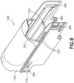
FIG. 9 is a top perspective view of a cassette body of the drug delivery device ofFIG. 1 ; -
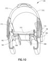
FIG. 10 is a bottom perspective view of the cassette body ofFIG. 9 ; -
FIG. 11 is a detail perspective view of the cassette body ofFIG. 9 ; and -
FIG. 12 is a cross-sectional detail view of the drug delivery device ofFIG. 1 . - The following description is provided to enable those skilled in the art to make and use the described embodiments contemplated for carrying out the invention. Various modifications, equivalents, variations, and alternatives, however, will remain readily apparent to those skilled in the art. Any and all such modifications, variations, equivalents, and alternatives are intended to fall within the spirit and scope of the present invention.
- For purposes of the description hereinafter, the terms "upper", "lower", "right", "left", "vertical", "horizontal", "top", "bottom", "lateral", "longitudinal", and derivatives thereof shall relate to the invention as it is oriented in the drawing figures. However, it is to be understood that the invention may assume various alternative variations, except where expressly specified to the contrary. It is also to be understood that the specific devices illustrated in the attached drawings, and described in the following specification, are simply exemplary embodiments of the invention. Hence, specific dimensions and other physical characteristics related to the embodiments disclosed herein are not to be considered as limiting.
- It should be understood that any numerical range recited herein is intended to include all values and sub-ranges subsumed therein. For example, a range of " 1 to 10" is intended to include all sub-ranges between (and including) the recited minimum value of 1 and the recited maximum value of 10, that is, having a minimum value equal to or greater than 1 and a maximum value of equal to or less than 10.
- When used in relation to a component of a drug delivery device, the term "distal" refers to a portion of said component nearest to a patient. When used in relation to a component of a drug delivery device, the term "proximal" refers to a portion of said component farthest from the patient.
- As used herein, the term "at least one of" is synonymous with "one or more of'. For example, the phrase "at least one of A, B, and C" means any one of A, B, and C, or any combination of any two or more of A, B, and C. For example, "at least one of A, B, and C" includes one or more of A alone; or one or more of B alone; or one or more of C alone; or one or more of A and one or more of B; or one or more of A and one or more of C; or one or more of B and one or more of C; or one or more of all of A, B, and C. Similarly, as used herein, the term "at least two of' is synonymous with "two or more of'. For example, the phrase "at least two of D, E, and F" means any combination of any two or more of D, E, and F. For example, "at least two of D, E, and F" includes one or more of D and one or more of E; or one or more of D and one or more of F; or one or more of E and one or more of F; or one or more of all of D, E, and F.
- International Patent Application Publication Nos.
WO 2020/173991 ,WO 2020/173992 ,WO 2020/173993 ,WO 2020/173994 , andWO 2020/173995 are incorporated herein by reference in their entirety. - Turning to
FIGS. 1-5 , shown is adrug delivery device 100. Thedrug delivery device 100 includes afirst subassembly 110, asecond subassembly 140, and asyringe 116. Thefirst subassembly 110 may include alower housing shell 112, acap 114, asyringe holder 118, aneedle cover 124, and acassette body 128. Thesecond subassembly 140 may include a drive assembly including aplunger body 150. Theplunger body 150 includes aplunger rod 152 and aspring guide member 154 including adrive member 156 and adrive opening 158. Thesecond subassembly 140 may further include amotor body 159, alever actuation member 130, and anupper housing shell 142. Thesyringe 116 may be received by thesyringe holder 118 and includes abarrel 117, astopper 122, aneedle 120, and a rigid needle shield (RNS) 126. Although an RNS is utilized in the example shown in the accompanying drawings, other suitable needle shield arrangements may be utilized. Thelower housing shell 112, thecassette body 128, and theupper housing shell 142 generally form a housing for receiving the various components of thedrug delivery device 100, although other suitable housing arrangements may be utilized. Thefirst subassembly 110 and thesecond subassembly 140 may be secured to each other during assembly by a locking clip, although other suitable arrangements may be utilized. Theupper housing shell 142 includes anouter lip 143 configured to fit around aninner lip 113 of thelower housing shell 112 when thedevice 100 is assembled. Thedrug delivery device 100 may be an auto-injector, although the features described herein may be incorporated into other suitable drug delivery devices. - With continued reference to
FIG. 2 , thedrive member 156 may be a compression spring received within adrive opening 158 defined by theplunger body 150, although other suitable drive members may be utilized, including, but not limited to, compressed gas, an electric motor, hydraulic pressure, other types of springs, etc. Thedrive member 156 engages theplunger body 150 and themotor body 159 and biases theplunger body 150 in a direction extending from thesecond subassembly 140 toward thefirst subassembly 110. Theplunger body 150 defines a lever opening that receives thelever actuation member 130 and defines the rotation axis of thelever actuation member 130. Thelever actuation member 130 prevents movement of theplunger body 150 when thelever actuation member 130 is in the locked position through engagement of thelever actuation member 130 with themotor body 159. Upon rotation of thelever actuation member 130 from the locked position to the released position, thelever actuation member 130 is disengaged from themotor body 159 thereby allowing thedrive member 156 to move theplunger body 150 and theplunger rod 152 toward thefirst subassembly 110. Theplunger rod 152 and thedrive member 156 are spaced from and parallel to each other and extend in a longitudinal direction of thedevice 100. - The
spring guide member 154 is secured to theupper housing shell 142 and received within thedrive opening 158 of theplunger body 150. Thedrive member 156 is received by thespring guide member 154 such that thedrive member 156 is positioned between theplunger body 150 and thespring guide member 154. In some embodiments, the drive assembly may also include a plunger rod cover (not shown) that receives theplunger rod 152 of theplunger body 150. The plunger rod cover may be configured to guide insertion of theplunger rod 152 into thebarrel 117 of thesyringe 116 and engage thestopper 122 to dispense the medicament from thebarrel 117 of thesyringe 116. - The
drug delivery device 100 is configured to automatically deliver a dose of medicament from thesyringe 116 to a patient upon actuation of thedevice 100. More specifically, upon actuation of thedrug delivery device 100, the drive assembly is configured to engage thestopper 122 of thesyringe 116, displace thesyringe 116 such that theneedle 120 pierces the skin of the patient, and displace thestopper 122 within thebarrel 117 of thesyringe 116 to deliver the medicament within thebarrel 117. Thedrug delivery device 100 includes a storage position, a pre-use position, an actuation position, an injection position, and a post-use position, as described in International Patent Application Publication Nos.WO 2020/173991 ,WO 2020/173992 ,WO 2020/173993 ,WO 2020/173994 , andWO 2020/173995 . - The
needle cover 124 is configured to shield theneedle 120 of thesyringe 116 from the patient when thedevice 100 is in the pre-use and the post-use positions. In particular, theneedle cover 124 is moveable between a pre-use position, an actuation position, and a post-use positon, with aspring 125 biasing theneedle cover 124 towards the pre-use position and the post-use position. Thespring 125 may be positioned between theneedle cover 124 and thesyringe holder 118, although other suitable arrangements may be utilized. - The
lever actuation member 130 is moveable between a locked position where movement of the drive assembly is prevented and a released position where movement of the drive assembly is allowed. More specifically, thelever actuation member 130 is rotatable about a rotation axis between the locked position and the released position. When thelever actuation member 130 is in the locked position, thelever actuation member 130 is engaged with themotor body 159 and the drive assembly to prevent movement of the drive assembly. - When the
lever actuation member 130 is in the released position, which may be achieved by pressing theneedle cover 124 onto the patient's skin at the site of injection, shifting the needle cover proximally into thelower housing shell 112, thelever actuation member 130 is disengaged from themotor body 159 thereby allowing movement of the drive assembly toward thesyringe 116. The rotation axis of thelever actuation member 130 extends perpendicular to a longitudinal axis of thedevice 100, although other suitable arrangements may be utilized. -
FIGS. 3 and 4 illustrate thesecond subassembly 140 and thefirst subassembly 110, respectively, as these subassemblies may be provided for final assembly of thedevice 100. As shown inFIG. 3 , asafety pin 200 is inserted through apertures 164 (seeFIG. 6 ) of themotor body 159. Theapertures 164 are located in proximity to a distal end of theplunger body 150 so that with thesafety pin 200 inserted through theapertures 164, thesafety pin 200 prevents rotation of thelever actuation member 130 and unintentional actuation of thedrive member 156. As will be described, thesafety pin 200 is removed prior to or during final assembly of thedevice 100. - Referring now to
FIGS. 6-8 , themotor body 159 is generally U-shaped and includes a pair of opposingsidewalls 326 configured to receive theplunger body 150 therebetween. Themotor body 159 defines thesafety pin apertures 164 extending transversely through thesidewalls 326 to facilitate insertion of the safety pin 200 (seeFIG. 3 ). Themotor body 159 further includes at least onecassette clip 328 extending from therespective sidewalls 326 for engaging complementary openings 330 (seeFIG. 9 ) defined by thecassette body 128. Engagement of the at least onecassette clip 328 with theopenings 330 secures themotor body 159 to thecassette body 128, which is discussed in more detail below. The at least onecassette clip 328 includes anangled face 332 and aplanar face 334, which are configured to allow insertion of the at least onecassette clip 328 into the correspondingopenings 330 of thecassette body 128, but prevent easy removal of the cassette clips 328 once inserted into theopenings 330 of thecassette body 128. - The
motor body 159 is configured to be inserted in theupper housing shell 142 of thesecond subassembly 140. Themotor body 159 includes at least oneshell stop 360 extending outward from the opposingsidewalls 326 of themotor body 159. Eachshell stop 360 has a planarproximal face 362 configured to engage an internal structure of theupper housing shell 142 to index themotor body 159 in theupper housing shell 142. The at least oneshell stop 360 extends a sufficient distance outward from thesidewalls 326 ofmotor body 159 so that the at least oneshell stop 360 remains at least partially engaged with the corresponding internal structure of theupper housing shell 142 when thesidewalls 326 of themotor body 159 are deflected inward during connection of themotor body 159 to thecassette body 128. In particular, each of the at least one shell stops 360 includes acantilevered end 364. - Each of the
sidewalls 326 of themotor body 159 includes acontact surface 160 for engaging with thecassette body 128. Thecontact surface 160 is configured to slide along a corresponding contact surface 180 (seeFIGS. 10-11 ) of thecassette body 128. The contact surfaces 160 of themotor body 159 are provided on inside faces of thesidewalls 326 in the illustrated embodiment, but in other embodiments the contact surfaces 160 may be provided on the outside of thesidewalls 326 with corresponding modifications made to thecassette body 128. The contact surfaces 160 of themotor body 159 may be planar, substantially vertical surfaces, though other profiles are within the scope of the present disclosure. The contact surfaces 160 of themotor body 159 may be configured for continuous contact with the corresponding contact surfaces 180 of thecassette body 128 along the length of the contact surfaces 160, 180. In some embodiments, the contact surfaces 160, 180 may be configured for intermittent contact along the length of the contact surfaces 160, 180. In non-limiting embodiments,contact surface 180 has a slope that provides for ease of assembly offirst subassembly 110 andsecond subassembly 140. - On the opposite side of each
sidewall 326 relative to the contact surface 160 (i.e., on the outside face of thesidewall 326 in the illustrated embodiment), themotor body 159 includes at least oneprotrusion 162 configured to maintain sliding contact between thecontact surface 160 of themotor body 159 and thecorresponding contact surface 180 of thecassette body 128. In particular, theprotrusion 162 may be located and sized so as to engage a corresponding wall surface 182 (seeFIG. 9-10 ) of thecassette body 128, which in turn forces thecontact surface 160 of themotor body 159 into contact with thecorresponding contact surface 180 of thecassette body 128. Thus, lateral slop between the contact surfaces 160 of themotor body 159 and the contact surfaces 180 of thecassette body 128 is eliminated. Even in the event of deformation of themotor body 159 prior to assembly, or imprecise manufacturing of themotor body 159, the contact surfaces 160 andprotrusions 162 interact with thecassette body 128 to hold themotor body 159 in the intended shape to ensure smooth assembly and operation of thedevice 100. In various embodiments, the at least oneprotrusion 162 may include a single protrusion or multiple protrusions provided at intervals along the length of thesidewall 326. The at least oneprotrusion 162 may include a curved outer surface, as shown in the accompanying drawings, but other profiles are within the scope of the present disclosure. - Referring to
FIGS. 9-11 , thecassette body 128 is generally U-shaped and configured to fit within thelower housing shell 112 and receive thesyringe 116 and various other components as described herein in connection withFIGS. 1-4 . Thecassette body 128 includes opposingsidewalls 170, the inside of which may include thewall surface 182 to which theprotrusions 162 of themotor body 159 engage. Thecassette body 128 further includes theopenings 330 that receive the corresponding cassette clips 328 (seeFIG. 6 ) of themotor body 159 when thedevice 100 is assembled. Thecassette body 128 includes aneedle cover clip 364 that engage theneedle cover 124 to restrict the axial movement of theneedle cover 124 relative to thecassette body 128. Thecassette body 128 further includesmotor body ribs 368 and upperhousing shell ribs 370, which are configured to engage corresponding portions of themotor body 159 and thelower housing shell 112, respectively, to aid in the assembly of thedevice 100. Themotor body ribs 368 may include the contact surfaces 180 configured to engage the corresponding contact surfaces 160 of themotor body 159. The contact surfaces 180 may have a complementary profile to the corresponding contact surfaces 160 of themotor body 159. For example, the contact surfaces 180 may be substantially planar, vertical surfaces as shown in the accompanying drawings. In some embodiments, the contact surfaces 180 extend substantially the entire length of themotor body ribs 368. Thecassette body 128 also includes syringe holder stops 372, which are configured to engage portions of thesyringe holder 118 to limit the axial movement of thesyringe holder 118 relative to thecassette body 128. - Referring now to
FIG. 12 , a cross section of the device is illustrated to show the interaction between thecassette body 128 and themotor body 159. Each of theprotrusions 162 of themotor body 159 engages thecorresponding wall surface 182 of thecassette body 128. The interaction of theprotrusions 162 and the wall surfaces 182 forces the contact surfaces 160 of themotor body 159 into engagement with the contact surfaces 180 of thecassette body 128, thereby defining a predetermined distance D between inside faces of thesidewalls 326 of themotor body 159. Likewise, interaction of theprotrusions 162 and the wall surfaces 182 forces thesidewalls 326 of themotor body 159 parallel to one another. Due to thecassette body 128 maintaining the shape of themotor body 159 in this manner, assembly of thedevice 100 is improved, friction between interacting components is reduced, and more reliable drug delivery is achieved. For example, consistency of the predetermined distance D prevents jamming of thelever actuation member 130 against thesidewalls 326 of themotor body 159. - Although the present disclosure has been described in detail for the purpose of illustration based on what is currently considered to be the most practical and preferred embodiments, it is to be understood that such detail is solely for that purpose and that the present disclosure is not limited to the disclosed embodiments, but, on the contrary, is intended to cover modifications and equivalent arrangements that are within the spirit and scope of the appended claims. For example, it is to be understood that the present disclosure contemplates that, to the extent possible, one or more features of any embodiment can be combined with one or more features of any other embodiment.
Claims (15)
- A drug delivery device comprising:an upper housing shell;a lower housing shell;a syringe comprising a barrel, a stopper, and a needle, at least a portion of the syringe positioned within the lower housing shell;a drive assembly comprising a plunger body configured to move the stopper within the barrel upon actuation of the drive assembly;a cassette body configured to receive the syringe; anda motor body configured to engage the cassette body,wherein the motor body comprises:a pair of sidewalls; anda contact surface provided on each of the pair of sidewalls, the contact surface engaging a corresponding contact surface of the cassette body.
- The drug delivery device of claim 1, wherein the contact surface of the motor body comprises a planar, substantially vertical surface.
- The drug delivery device of claim 1 or 2, wherein the corresponding contact surface of the cassette body comprises a planar, substantially vertical surface.
- The drug delivery device of any of claims 1-3, wherein the contact surface of the motor body continuously contacts the corresponding contact surface of the cassette body contact along a length of the contact surface of the motor body.
- The drug delivery device of any of claims 1-4, wherein the cassette body comprises at least one motor body rib comprising the contact surface of the cassette body.
- The drug delivery device of claim 5, wherein the contact surface of the cassette body extends substantially the entire length of the at least one motor body rib.
- The drug delivery device of any of claims 1-6, wherein the at least contact surface of the motor body is provided on an inside face of the sidewall of the motor body.
- The drug delivery device of any of claims 1-7, wherein the motor body comprises at least one protrusion configured to engage a corresponding wall surface of the cassette body.
- The drug delivery device of claim 8, wherein the cassette body comprises a pair of sidewalls comprising the corresponding wall surface.
- The drug delivery device of claim 8 or 9, wherein the protrusion comprises a curved outer surface.
- The drug delivery device of any of claims 8-10, wherein interaction of the at least one protrusion and the corresponding wall surface of the cassette body forces the contact surface of the motor body into engagement with the contact surface of the cassette body.
- The drug delivery device of any of claims 8-11, wherein contact between the at least one protrusion and the corresponding wall surface of the cassette body defines a predetermined distance between inside faces of the sidewalls of the motor body.
- The drug delivery device of any of claims 8-12, wherein contact between the at least one protrusion and the corresponding wall surface of the cassette body forces the sidewalls of the motor body parallel to one another.
- The drug delivery device of any of claims 8-13, wherein the at least one protrusion and the contact surface of the motor body is provided on opposite sides of the sidewall of the motor body.
- The drug delivery device of any of claims 8-14, wherein the at least one protrusion is provided on an outside face of the sidewall of the motor body.
Priority Applications (3)
| Application Number | Priority Date | Filing Date | Title |
|---|---|---|---|
| EP23158590.2A EP4420695A1 (en) | 2023-02-24 | 2023-02-24 | Auto-injector with motor body and cassette body |
| US18/585,402 US20240285856A1 (en) | 2023-02-24 | 2024-02-23 | Auto-Injector With Motor Body and Cassette Body |
| CN202410206571.4A CN118542997A (en) | 2023-02-24 | 2024-02-26 | Auto injector with motor body and cartridge |
Applications Claiming Priority (1)
| Application Number | Priority Date | Filing Date | Title |
|---|---|---|---|
| EP23158590.2A EP4420695A1 (en) | 2023-02-24 | 2023-02-24 | Auto-injector with motor body and cassette body |
Publications (1)
| Publication Number | Publication Date |
|---|---|
| EP4420695A1 true EP4420695A1 (en) | 2024-08-28 |
Family
ID=85382699
Family Applications (1)
| Application Number | Title | Priority Date | Filing Date |
|---|---|---|---|
| EP23158590.2A Pending EP4420695A1 (en) | 2023-02-24 | 2023-02-24 | Auto-injector with motor body and cassette body |
Country Status (3)
| Country | Link |
|---|---|
| US (1) | US20240285856A1 (en) |
| EP (1) | EP4420695A1 (en) |
| CN (1) | CN118542997A (en) |
Citations (6)
| Publication number | Priority date | Publication date | Assignee | Title |
|---|---|---|---|---|
| WO2020173991A1 (en) | 2019-02-26 | 2020-09-03 | Becton Dickinson France | Auto-injector with needle cover |
| WO2020173993A1 (en) | 2019-02-26 | 2020-09-03 | Becton Dickinson France | Auto-injector with audio indicator |
| WO2020173992A1 (en) | 2019-02-26 | 2020-09-03 | Becton Dickinson France | Auto-injector with locking clip |
| WO2020173994A1 (en) | 2019-02-26 | 2020-09-03 | Becton Dickinson France | Auto-injector with actuation prevention cap |
| WO2020173995A1 (en) | 2019-02-26 | 2020-09-03 | Becton Dickinson France | Auto-injector with cap |
| WO2022254004A1 (en) * | 2021-06-03 | 2022-12-08 | Becton Dickinson France | Safety clip for medical injection device |
-
2023
- 2023-02-24 EP EP23158590.2A patent/EP4420695A1/en active Pending
-
2024
- 2024-02-23 US US18/585,402 patent/US20240285856A1/en active Pending
- 2024-02-26 CN CN202410206571.4A patent/CN118542997A/en active Pending
Patent Citations (10)
| Publication number | Priority date | Publication date | Assignee | Title |
|---|---|---|---|---|
| WO2020173991A1 (en) | 2019-02-26 | 2020-09-03 | Becton Dickinson France | Auto-injector with needle cover |
| WO2020173993A1 (en) | 2019-02-26 | 2020-09-03 | Becton Dickinson France | Auto-injector with audio indicator |
| WO2020173992A1 (en) | 2019-02-26 | 2020-09-03 | Becton Dickinson France | Auto-injector with locking clip |
| WO2020173994A1 (en) | 2019-02-26 | 2020-09-03 | Becton Dickinson France | Auto-injector with actuation prevention cap |
| WO2020173995A1 (en) | 2019-02-26 | 2020-09-03 | Becton Dickinson France | Auto-injector with cap |
| US20220111152A1 (en) * | 2019-02-26 | 2022-04-14 | Becton Dickinson France | Auto-injector with needle cover |
| US20220134018A1 (en) * | 2019-02-26 | 2022-05-05 | Becton Dickinson France | Auto-injector with actuation prevention cap |
| US20220152309A1 (en) * | 2019-02-26 | 2022-05-19 | Becton Dickinson France | Auto-injector with audio indicator |
| US20220160964A1 (en) * | 2019-02-26 | 2022-05-26 | Becton Dickinson France | Auto-injector with locking clip |
| WO2022254004A1 (en) * | 2021-06-03 | 2022-12-08 | Becton Dickinson France | Safety clip for medical injection device |
Also Published As
| Publication number | Publication date |
|---|---|
| US20240285856A1 (en) | 2024-08-29 |
| CN118542997A (en) | 2024-08-27 |
Similar Documents
| Publication | Publication Date | Title |
|---|---|---|
| US20240285864A1 (en) | Auto-Injector With Assembly and Alignment Features | |
| EP4420696A1 (en) | Cassette body clip for auto-injector | |
| CN113056297B (en) | Medical injection system | |
| US10780226B2 (en) | Trigger assembly for automatic medication injection device | |
| JP4865863B2 (en) | Needle protector with restrained protective position | |
| CA3127575C (en) | Auto-injector with locking clip | |
| US10864326B2 (en) | Medication injection device with automatic needle retraction following injection | |
| EP3930799B1 (en) | Auto-injector with needle cover | |
| US20250144319A1 (en) | Rotator for a medicament delivery device | |
| WO2018167495A1 (en) | Injection device | |
| JP7523529B2 (en) | Needle assembly having needle shield and plug | |
| EP4420695A1 (en) | Auto-injector with motor body and cassette body | |
| CN110650760A (en) | injection equipment | |
| EP4420700A1 (en) | Drug delivery device comprising a cap | |
| EP4420698A1 (en) | Stabilized plunger body for autoinjector | |
| TWI867967B (en) | Injection device with an improved triggering mechanism | |
| EP4420697A1 (en) | End-of-dose indicator for drug-delivery device | |
| TWI880638B (en) | Injection device with an improved needle guard lockout mechanism | |
| CA3127716C (en) | Auto-injector with needle cover | |
| WO2026055169A1 (en) | Lockable needle shield remover assembly for wearable injector | |
| CN118660730A (en) | Rotating body for drug delivery device | |
| CN121059947A (en) | Safety device, medical kit and medical assembly with same |
Legal Events
| Date | Code | Title | Description |
|---|---|---|---|
| PUAI | Public reference made under article 153(3) epc to a published international application that has entered the european phase |
Free format text: ORIGINAL CODE: 0009012 |
|
| STAA | Information on the status of an ep patent application or granted ep patent |
Free format text: STATUS: THE APPLICATION HAS BEEN PUBLISHED |
|
| AK | Designated contracting states |
Kind code of ref document: A1 Designated state(s): AL AT BE BG CH CY CZ DE DK EE ES FI FR GB GR HR HU IE IS IT LI LT LU LV MC ME MK MT NL NO PL PT RO RS SE SI SK SM TR |
|
| STAA | Information on the status of an ep patent application or granted ep patent |
Free format text: STATUS: REQUEST FOR EXAMINATION WAS MADE |
|
| 17P | Request for examination filed |
Effective date: 20250225 |