EP4420642A1 - Intraocular illumination device and attachment for intraocular illumination - Google Patents
Intraocular illumination device and attachment for intraocular illumination Download PDFInfo
- Publication number
- EP4420642A1 EP4420642A1 EP22883662.3A EP22883662A EP4420642A1 EP 4420642 A1 EP4420642 A1 EP 4420642A1 EP 22883662 A EP22883662 A EP 22883662A EP 4420642 A1 EP4420642 A1 EP 4420642A1
- Authority
- EP
- European Patent Office
- Prior art keywords
- fiber
- holder
- intraocular illumination
- illumination device
- eye
- Prior art date
- Legal status (The legal status is an assumption and is not a legal conclusion. Google has not performed a legal analysis and makes no representation as to the accuracy of the status listed.)
- Pending
Links
Images





Classifications
-
- G—PHYSICS
- G02—OPTICS
- G02B—OPTICAL ELEMENTS, SYSTEMS OR APPARATUS
- G02B21/00—Microscopes
- G02B21/06—Means for illuminating specimens
-
- A—HUMAN NECESSITIES
- A61—MEDICAL OR VETERINARY SCIENCE; HYGIENE
- A61B—DIAGNOSIS; SURGERY; IDENTIFICATION
- A61B3/00—Apparatus for testing the eyes; Instruments for examining the eyes
- A61B3/0008—Apparatus for testing the eyes; Instruments for examining the eyes provided with illuminating means
-
- A—HUMAN NECESSITIES
- A61—MEDICAL OR VETERINARY SCIENCE; HYGIENE
- A61B—DIAGNOSIS; SURGERY; IDENTIFICATION
- A61B3/00—Apparatus for testing the eyes; Instruments for examining the eyes
- A61B3/10—Objective types, i.e. instruments for examining the eyes independent of the patients' perceptions or reactions
- A61B3/13—Ophthalmic microscopes
-
- A—HUMAN NECESSITIES
- A61—MEDICAL OR VETERINARY SCIENCE; HYGIENE
- A61B—DIAGNOSIS; SURGERY; IDENTIFICATION
- A61B3/00—Apparatus for testing the eyes; Instruments for examining the eyes
- A61B3/10—Objective types, i.e. instruments for examining the eyes independent of the patients' perceptions or reactions
- A61B3/14—Arrangements specially adapted for eye photography
-
- A—HUMAN NECESSITIES
- A61—MEDICAL OR VETERINARY SCIENCE; HYGIENE
- A61B—DIAGNOSIS; SURGERY; IDENTIFICATION
- A61B90/00—Instruments, implements or accessories specially adapted for surgery or diagnosis and not covered by any of the groups A61B1/00 - A61B50/00, e.g. for luxation treatment or for protecting wound edges
- A61B90/20—Surgical microscopes characterised by non-optical aspects
-
- A—HUMAN NECESSITIES
- A61—MEDICAL OR VETERINARY SCIENCE; HYGIENE
- A61F—FILTERS IMPLANTABLE INTO BLOOD VESSELS; PROSTHESES; DEVICES PROVIDING PATENCY TO, OR PREVENTING COLLAPSING OF, TUBULAR STRUCTURES OF THE BODY, e.g. STENTS; ORTHOPAEDIC, NURSING OR CONTRACEPTIVE DEVICES; FOMENTATION; TREATMENT OR PROTECTION OF EYES OR EARS; BANDAGES, DRESSINGS OR ABSORBENT PADS; FIRST-AID KITS
- A61F9/00—Methods or devices for treatment of the eyes; Devices for putting in contact-lenses; Devices to correct squinting; Apparatus to guide the blind; Protective devices for the eyes, carried on the body or in the hand
- A61F9/007—Methods or devices for eye surgery
-
- G—PHYSICS
- G02—OPTICS
- G02B—OPTICAL ELEMENTS, SYSTEMS OR APPARATUS
- G02B21/00—Microscopes
- G02B21/0004—Microscopes specially adapted for specific applications
- G02B21/0012—Surgical microscopes
-
- G—PHYSICS
- G02—OPTICS
- G02B—OPTICAL ELEMENTS, SYSTEMS OR APPARATUS
- G02B6/00—Light guides; Structural details of arrangements comprising light guides and other optical elements, e.g. couplings
- G02B6/0001—Light guides; Structural details of arrangements comprising light guides and other optical elements, e.g. couplings specially adapted for lighting devices or systems
- G02B6/0005—Light guides; Structural details of arrangements comprising light guides and other optical elements, e.g. couplings specially adapted for lighting devices or systems the light guides being of the fibre type
- G02B6/0006—Coupling light into the fibre
-
- G—PHYSICS
- G02—OPTICS
- G02B—OPTICAL ELEMENTS, SYSTEMS OR APPARATUS
- G02B6/00—Light guides; Structural details of arrangements comprising light guides and other optical elements, e.g. couplings
- G02B6/0001—Light guides; Structural details of arrangements comprising light guides and other optical elements, e.g. couplings specially adapted for lighting devices or systems
- G02B6/0005—Light guides; Structural details of arrangements comprising light guides and other optical elements, e.g. couplings specially adapted for lighting devices or systems the light guides being of the fibre type
- G02B6/0008—Light guides; Structural details of arrangements comprising light guides and other optical elements, e.g. couplings specially adapted for lighting devices or systems the light guides being of the fibre type the light being emitted at the end of the fibre
Definitions
- the present disclosure relates to an intraocular illumination device and an intraocular illumination attachment.
- JP 2005-230558 A proposes a technique in which a light source is disposed at a position opposite to the eye with respect to an objective lens inside a microscope, and the inside of the eye is illuminated from the outside the eye with light passing through the objective lens.
- a light source is disposed at a position opposite to the eye with respect to the objective lens and light enters the eye through the objective lens, it is difficult to obtain intraocular illumination having a sufficient light amount and an irradiation range.
- the light source is disposed inside the microscope, it is necessary to newly purchase a microscope having such a special structure, and there is a disadvantage that an existing microscope cannot be used.
- a technique capable of providing intraocular illumination from outside the eye with a sufficient light amount and range is desired.
- a technique capable of realizing intraocular illumination from the outside the eye while using an existing microscope is desired.
- An intraocular illumination device including:
- An intraocular illumination attachment is an intraocular illumination attachment disposed between an objective lens of a microscope and an eye during eye surgery or examination, the intraocular illumination attachment including:
- the tip portion of the fiber that guides light from the light source is supported by the holder between the objective lens of the microscope and the eye, and the tip portion of the fiber is provided with the reflecting portion that reflects the light guided through the fiber toward the inside of the eye. Therefore, the light can be emitted toward the inside of the eye from a position sufficiently close to the eye without passing through the lens. Therefore, it is possible to obtain intraocular illumination from the outside the eye with a sufficient light amount and range.
- the tip portion of the fiber is supported by the holder so as not to move, it is possible for an operator to operate surgical instrument with both hands, that is, it is possible to practice a dual technique.
- An intraocular illumination device is the intraocular illumination device according to the first aspect, in which
- An intraocular illumination device is the intraocular illumination device according to the first aspect, in which
- An intraocular illumination device is the intraocular illumination device according to any one of the first to third aspects, in which a thickness of the holder is 10 mm or less.
- the holder can be easily disposed in a narrow space between the objective lens of the microscope and the eye.
- An intraocular illumination device is the intraocular illumination device according to any one of the first to fourth aspects, in which the holder supports a plurality of the tip portions of the fibers.
- the holder since the holder supports the plurality of tip portions of the fibers, it is possible to increase the light amount and range of intraocular illumination.
- An intraocular illumination device is the intraocular illumination device according to the fifth aspect, in which a plurality of the reflecting portions provided at each of the plurality of tip portions are disposed in the holder so as to be arranged at equal intervals along a circumferential direction about an optical axis of the microscope.
- a wide range in the eye can be uniformly illuminated.
- An intraocular illumination device is the intraocular illumination device according to any one of the first to sixth aspects, in which the holder is provided with an attachment portion attachable to a lens unit of the microscope.
- An intraocular illumination device is the intraocular illumination device according to any one of the first to sixth aspects, in which the holder is configured integrally with a lens unit of the microscope.
- An intraocular illumination device is the intraocular illumination device according to any one of the first to eighth aspects, in which a through-hole is formed in the holder coaxially with the optical axis of the microscope, a groove or hole is formed to extend outward from a vicinity of the through-hole in plan view, and the tip portion of the fiber is inserted into the groove or hole formed in the holder and supported.
- the through-hole is formed coaxially with the optical axis of the microscope in the holder, a bright field of view can be obtained when observed with the microscope.
- the tip portion of the fiber is inserted into the groove or hole formed in the holder and supported, the configuration for supporting the tip portion of the fiber can be realized with a very simple structure, and the manufacturing cost of the holder can be reduced.
- An intraocular illumination device is the intraocular illumination device according to the ninth aspect, in which the tip portion of the fiber is positionally adjustable along the groove or hole in a state of being supported by the holder.
- An intraocular illumination device is the intraocular illumination device according to the tenth aspect, in which the tip portion of the fiber is positionally adjusted along the groove or hole, so that the reflecting portion can be brought close to a range within 5 mm from the optical axis of the microscope.
- a window portion can be brought close to a range within 5 mm from the optical axis of the microscope, so that light emitted from the window portion can be efficiently introduced into the eye from the portion of the iris.
- An intraocular illumination device is the intraocular illumination device according to any one of the ninth to eleventh aspects, in which a number of the tip portions of the fibers is four, the holder is formed with four of the grooves or holes, and the four grooves or holes are formed to extend in directions of 0°, 90°, 180°, and 270°, respectively, in polar coordinates about the optical axis of the microscope.
- An intraocular illumination device is the intraocular illumination device according to any one of the ninth to eleventh aspects, in which a number of the tip portions of the fibers is four, the holder is formed with four of the grooves or holes, a first groove or hole is formed to extend in a direction of 0° from a position of 0°, a second groove or hole is formed to extend in a direction of 180° from a position of 180°, a third groove or hole is formed to extend in a direction of 0° or 180° from a position of 90°, and a fourth groove or hole is formed to extend in a direction of 0° or 180° from a position of 270° in polar coordinates about the optical axis of the microscope.
- An intraocular illumination device is the intraocular illumination device according to any one of the first to thirteenth aspects, in which an NA of the fiber on an emitting side is 0.55 or less.
- An intraocular illumination device is the intraocular illumination device according to any one of the first to fourteenth aspects, in which the fiber is branched between the light source and the illumination unit.
- a number of illumination units can be increased without increasing a number of light sources.
- An intraocular illumination device is the intraocular illumination device according to any one of the first to fifteenth aspects, in which the light source is at least one of a xenon lamp, a halogen lamp, and an LED.
- a xenon lamp, a halogen lamp, or an LED existing in an operating room or an inspection room it is possible to use a xenon lamp, a halogen lamp, or an LED existing in an operating room or an inspection room as the light source, and it is convenient since it is not necessary to newly prepare a light source.
- An intraocular illumination attachment is an intraocular illumination attachment disposed between an objective lens of a microscope and an eye during eye surgery or examination, the intraocular illumination attachment including:
- the intraocular illumination attachment is disposed between the objective lens of the microscope and the eye during eye surgery or examination, that is, disposed outside the microscope, intraocular illumination from outside the eye can be realized while utilizing the existing microscope.
- the illumination unit including the mirror that reflects the light guided through the fiber toward the inside of the eye is supported by the holder between the objective lens of the microscope and the eye, the light can be emitted toward the inside of the eye from a position sufficiently close to the eye without passing through the lens. Therefore, it is possible to obtain intraocular illumination from the outside the eye with a sufficient light amount and range.
- the illumination unit is supported by the holder so as not to move, it is possible for an operator to operate the surgical instrument with both hands, that is, it is possible to practice the dual technique.
- An intraocular illumination attachment according to an eighteenth aspect of the embodiment is the intraocular illumination attachment according to the seventeenth aspect, in which a thickness of the holder is 10 mm or less.
- the holder can be easily disposed in a narrow space between the objective lens of the microscope and the eye.
- An intraocular illumination attachment is the intraocular illumination attachment according to the seventeenth or eighteenth aspect, in which the holder supports a plurality of the illumination units.
- the holder since the holder supports the plurality of illumination units, the light amount and range of intraocular illumination can be increased.
- An intraocular illumination attachment is the intraocular illumination attachment according to the nineteenth aspect, in which the plurality of illumination units are disposed such that window portions through which light reflected by the mirror is emitted are arranged at equal intervals along a circumferential direction about the optical axis of the microscope.
- a wide range in the eye can be uniformly illuminated.
- An intraocular illumination attachment is the intraocular illumination attachment according to any one of the seventeenth to twentieth aspects, in which the holder is provided with an attachment portion attachable to a lens unit of the microscope.
- the holder can be easily fixed so as not to move with respect to the lens unit.
- An intraocular illumination attachment is the intraocular illumination attachment according to any one of the seventeenth to 21th aspects, in which a through-hole is formed in the holder coaxially with an optical axis of the microscope, a groove or hole is formed to extend outward from a vicinity of the through-hole in plan view, and the illumination unit attached to the tip portion of the fiber is inserted into the groove or hole formed in the holder and supported.
- the through-hole is formed coaxially with the optical axis of the microscope in the holder, a bright field of view can be obtained when observed with the microscope.
- the illumination unit is inserted into the groove or hole formed in the holder and supported, the configuration for supporting the illumination unit can be realized with a very simple structure, and the manufacturing cost of the holder can be reduced.
- An intraocular illumination attachment according to a 23rd aspect of the embodiment is the intraocular illumination attachment according to the 22nd aspect, in which it is the intraocular illumination attachment according to claim 6, in which the illumination unit attached to the tip portion of the fiber is positionally adjustable along the groove or hole in a state of being supported by the holder.
- An intraocular illumination attachment is the intraocular illumination attachment according to the 23th aspect, in which the illumination unit attached to the tip portion of the fiber is positionally adjusted along the groove or hole, so that the window portion that emits the light reflected by the mirror can be brought close to a range within 5 mm from the optical axis of the microscope.
- a window portion can be brought close to the range within 5 mm from the optical axis of the microscope, so that light emitted from the window portion can be efficiently introduced into the eye from the portion of the iris.
- An intraocular illumination attachment is the intraocular illumination attachment according to any one of the 22nd to 24th aspects, in which a number of the illumination units is four, the holder is formed with four of the grooves or holes, and the four grooves or holes are formed to extend in directions of 0°, 90°, 180°, and 270°, respectively, in polar coordinates about the optical axis of the microscope.
- An intraocular illumination attachment is the intraocular illumination attachment according to any one of the 22nd to 24th aspects, in which a number of the illumination units is four, the holder is formed with four of the grooves or holes, a first groove or hole is formed to extend in a direction of 0° from a position of 0°, a second groove or hole is formed to extend in a direction of 180° from a position of 180°, a third groove or hole is formed to extend in a direction of 0° or 180° from a position of 90°, and a fourth groove or hole is formed to extend in a direction of 0° or 180° from a position of 270° in polar coordinates about the optical axis of the microscope.
- An intraocular illumination attachment according to a 27th aspect of the embodiment is the intraocular illumination attachment according to any one of the seventeenth to 26th aspects, in which the intraocular illumination attachment is disposable.
- the intraocular illumination attachment is disposed between the objective lens of the microscope and the eye during eye surgery or examination, so that the intraocular illumination attachment is easily contaminated.
- the intraocular illumination attachment is disposable, the intraocular illumination attachment is extremely hygienic and convenient.
- An intraocular illumination attachment according to a 28th aspect of the embodiment is the intraocular illumination attachment according to any one of the seventeenth to 27th aspects, in which an NA of the fiber on an emitting side is 0.55 or less.
- An intraocular illumination attachment according to a 29th aspect of the embodiment is the intraocular illumination attachment according to any one of the seventeenth to 28th aspects, in which the fiber is branched between the light source 15 and the illumination unit.
- a number of illumination units can be increased without increasing a number of light sources.
- An intraocular illumination attachment is the intraocular illumination attachment according to any one of the seventeenth to 29th aspects, in which the light source is at least one of a xenon lamp, a halogen lamp, and an LED.
- a xenon lamp, a halogen lamp, or an LED existing in an operating room or an inspection room it is possible to use a xenon lamp, a halogen lamp, or an LED existing in an operating room or an inspection room as the light source, and it is convenient since it is not necessary to newly prepare a light source.
- An intraocular illumination device including: the intraocular illumination attachment according to any one of the seventeenth to 30th aspects; and the fiber.
- a microscope for eye surgery or examination according to a 32nd aspect of the embodiment including: the intraocular illumination device according to any one of the first to sixteenth and 31th aspects.
- Fig. 1 is a schematic view illustrating a positional relationship between an intraocular illumination device 1 according to an embodiment, an objective lens 31 of a microscope, and an eye 20.
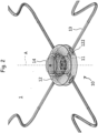
- Fig. 2 is an enlarged perspective view of the intraocular illumination device 1.
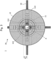
- Fig. 3 is a plan view of the intraocular illumination device 1 as viewed from the eye 20 side.
- the intraocular illumination device 1 has fibers (optical fibers) 13 that guide light from a light source 15, and an intraocular illumination attachment 10 attached to tip portions of the fibers 13.
- the intraocular illumination attachment 10 is disposed between the objective lens 31 of the microscope and the eye 20 during surgery or examination of the eye 20. Since the intraocular illumination attachment 10 is disposed between the objective lens 31 and the eye 20 and is easily contaminated, it may be disposable in consideration of hygiene. Note that the objective lens 31 of the microscope is accommodated in the lens unit 30.
- the intraocular illumination attachment 10 has illumination units 11 attached to the tip portions of the fibers 13 and a holder 12 that supports the illumination units 11.
- Fig. 6 is an enlarged perspective view illustrating the illumination unit 11 attached to the tip portion of the fiber 13.
- Fig. 7A is a longitudinal sectional view of the illumination unit 11, and
- Fig. 7B is a perspective view of the illumination unit 11.
- the illumination unit 11 has a cylindrical portion 110 having a cylindrical shape in which a tip portion is obliquely cut (for example, at an angle of 45°), and a mirror 111 attached to cover an opening exposed on a cut surface of the cylindrical portion 110.
- a material of the cylindrical portion 110 is, for example, brass.
- a window portion 112 is formed on an outer peripheral surface of the cylindrical portion 110 so as to correspond to a reflecting surface of the mirror 111.
- the tip portion of the fiber 13 is fixed to the cylindrical portion 110 in a state of being inserted from a proximal end portion of the cylindrical portion 110.
- the light emitted from the tip portion of the fiber 13 is reflected by the reflecting surface of the mirror 111 in a direction of 90° and then emitted to the outside through the window portion 112. That is, in the present embodiment, the reflecting portion that is provided at the tip portion of the fiber 13 and reflects the light guided through the fiber 13 toward the inside of the eye 20 is configured by the mirror 111 of the illumination unit 11.
- Fig. 4 is a perspective view of the holder 12 as viewed from the objective lens 31 side of the microscope.
- Fig. 5 is a perspective view of the holder 12 as viewed from the eye 20 side.
- the holder 12 has a substantially disk shape.
- a thickness T (length of the microscope in a direction of an optical axis A) of the holder 12 may be, for example, 10 mm or less, 9 mm or less, or 8 mm or less. Since the thickness of the holder 12 is sufficiently thin, the holder 12 can be easily disposed in a narrow space between an objective lens 23 of the microscope and the eye 20 during surgery or examination of the eye 20.
- a diameter WO of the holder 12 may be, for example, 40 to 50 mm.
- a material of the holder 12 is, for example, a resin.
- the holder 12 is provided with an attachment portion 14 attachable to the lens unit 30 of the microscope.
- the attachment portion 14 has a substantially cylindrical shape, and is provided on the surface of the holder 12 coaxially with the optical axis A of the microscope.
- a diameter of the attachment portion 14 is, for example, 20 to 25 mm, and a height of the attachment portion 14 is, for example, 10 to 15 mm.
- a screw hole is formed in an outer peripheral surface of the attachment portion 14. As illustrated in Fig. 1 , the holder 12 is fixed so as not to move with respect to the lens unit 30 by tightening a screw inserted into the screw hole in a state where the lens unit 30 of the microscope is inserted into the attachment portion 14.
- a through-hole 121 is formed in the holder 12 coaxially with the optical axis A of the microscope.
- grooves or holes 122 are formed in the holder 12 to extend outward from the vicinity of the through-hole 121 in plan view.
- the "groove or hole” refers to a structure in which a portion near the through-hole 121 has a groove shape (a contour line of a cross section is open), but a portion away from the through-hole 121 has a hole shape (a contour line of a cross section is closed).
- a diameter of the groove or hole 122 is substantially the same as a diameter of the cylindrical portion 110 of the illumination unit 11, and the illumination unit 11 attached to the tip portion of the fiber 13 is configured to be supported by being inserted into the groove or hole 122 formed in the holder 12.
- the illumination unit 11 attached to the tip portion of the fiber 13 can be positionally adjusted along the groove or hole 122 while being supported by the holder 12.
- the position of the illumination unit 11 By adjusting the position of the illumination unit 11, brightness of an eye fundus and a condition of a spot (illuminated portion) can be easily adjusted.
- the illumination unit 11 attached to the tip portion of the fiber 13 is positionally adjusted along the groove or hole 122, so that the window portion 112 that emits the light reflected by the mirror 111 can be brought close to the optical axis A of the microscope.
- an interval D between the optical axis A of the microscope and the window portion 112 may be brought close to a range within, for example, 5 mm or less. While the diameter of the iris 21 of the eye 20 is usually 10 to 12 mm, by bringing the window portion 112 close to the range within 5 mm from the optical axis A of the microscope, light emitted from the window portion 112 can be efficiently introduced into the eye 20 from the portion of the iris 21.
- a small groove 122a for rotation restriction may be formed adjacent to the groove or hole 122 for inserting the illumination unit 11.
- a projection (not illustrated) corresponding to the small groove 122a is provided on the outer peripheral surface of the cylindrical portion 110 of the illumination unit 11, and when the cylindrical portion 110 of the illumination unit 11 is inserted into the groove or hole 122 of the holder 12, the projection of the cylindrical portion 110 is inserted along the small groove 122a, so that the illumination unit 11 can be prevented from rotating about the axis of the fiber 13, and the direction of light emitted from the window portion 112 can be fixed so as not to move.
- Only one groove or hole 122 may be formed in the holder 12 to support only one illumination unit 11, or a plurality of grooves or holes 122 may be formed to support a plurality of illumination units 11.
- four grooves or holes 122 are formed in the holder 12 so as to support the four illumination units 11, but the present disclosure is not limited thereto.
- six or eight grooves or holes may be formed in the holder 12 so as to support six or eight illumination units 11. Since the holder 12 supports the plurality of illumination units 11, it is possible to increase the light amount and range of the intraocular illumination.
- the plurality of illumination units 11 may be disposed such that the window portions 112 that emit the light reflected by the mirror 111 are arranged at equal intervals along the circumferential direction about the optical axis A of the microscope.
- the four illumination units 11 are arranged at positions of 0°, 90°, 180°, and 270° in polar coordinates about the optical axis A of the microscope.
- four grooves or holes 122 are formed in the holder 12 to extend in the directions of 0°, 90°, 180°, and 270°, respectively, in the polar coordinates about the optical axis A of the microscope.
- the four fibers 13 each having the illumination unit 11 attached to the tip portion are inserted into the grooves or holes 122 from different directions of 0°, 90°, 180°, and 270° and supported.
- the window portion 112 of the illumination unit 11 is oriented to face the inside of the eye 20 (see Fig. 3 ), and light L emitted from the tip portion of the fiber 13 is reflected toward the inside of the eye 20 by the mirror 111 of the illumination unit 11.
- the illuminance of the light L emitted from the illumination unit 11 toward the inside of the eye 20 can be appropriately set according to the microscope to be used, but for example, the central illuminance at the eye fundus may be 10000 to 100000 lx.
- the illuminance is defined according to JIS Z 9110:2010.
- a numerical aperture (NA) of the fiber 13 on the emitting side may be 0.55 or less, 0.50 or less, 0.45 or less, or 0.40 or less.
- the numerical aperture (NA) is a value represented by nsin ⁇ when an angle of a vertex of a maximum conical light beam emitted from a core of the fiber 13 is 2 ⁇ and a refractive index of a medium in which the fiber 13 is present is n, and is according to the definition of JIS C 6820:2018. Since the numerical aperture (NA) of the fiber 13 is small, it is possible to emit light having sufficient directionality toward the inside of the eye, and thus, it is possible to increase the light amount and range of the intraocular illumination.
- the fiber 13 when the holder 12 supports the plurality of illumination units 11, the fiber 13 may be branched into a plurality of fibers between the light source 15 and each illumination unit 11.
- one fiber 13 extending from one light source 15 may be branched into four and then coupled to four illumination units 11, or one fiber 13 extending from one light source 15 may be branched into two and then coupled to two illumination units 11, and another fiber 13 extending from another light source 15 may be branched into two and then coupled to remaining two illumination units 11.
- the number of illumination units 11 can be increased without increasing the number of the light sources 15.
- the light source 15 may be at least one of a xenon lamp, a halogen lamp, and an LED (light emitting diode).
- a xenon lamp, a halogen lamp, or an LED existing in an operating room or an inspection room can be used as the light source 15, and it is convenient since it is not necessary to newly prepare a light source.
- the intraocular illumination attachment 10 is disposed between the objective lens 31 of the microscope and the eye 20 during surgery or examination of the eye 20, that is, disposed outside the microscope, intraocular illumination from the outside of the eye can be realized using the existing microscope.
- the illumination unit 11 including the mirror 111 that reflects the light guided through the fiber 13 toward the inside of the eye is supported by the holder 12 between the objective lens 31 of the microscope and the eye 20, the light can be emitted toward the inside of the eye from a position sufficiently close to the eye 20 without passing through the lens. Therefore, it is possible to obtain intraocular illumination from the outside the eye with a sufficient light amount and range.
- the illumination unit 11 is supported by the holder 12 so as not to move, it is possible for an operator to operate the surgical instrument with both hands, that is, it is possible to practice the dual technique.
- the holder 12 is provided with the attachment portion 14, and the holder 12 is fixed so as not to move with respect to the lens unit 30 of the microscope via the attachment portion 14.
- the present disclosure is not limited to such an aspect.
- the holder 12 may not be provided with the attachment portion 14, and the holder 12 may be supported so as not to move with respect to the lens unit 30 using a support jig (for example, a stand with a clamp) (not illustrated).
- the holder 12 may be configured integrally with the lens unit 30 of the microscope (non-detachable with respect to the lens unit 30).
- the holder 12 is disposed adjacent to the outside the lens unit 30, but the present disclosure is not limited thereto, and the holder 12 may be disposed inside the lens unit 30 as long as it is located between the objective lens 31 and the eye 20.
- the four grooves or holes 122 are formed to extend in the directions of 0°, 90°, 180°, and 270°, respectively, in the polar coordinates about the optical axis A of the microscope, and the four fibers 13 to each of which the illumination unit 11 is attached at the tip portion are inserted into the grooves or holes 122 from the directions different from each other of 0°, 90°, 180°, and 270° and supported.
- the present disclosure is not limited to such an aspect.
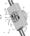
- Fig. 9 is an enlarged perspective view illustrating the intraocular illumination device 1 according to the modification
- Fig. 10 is a plan view of the intraocular illumination device 1 as viewed from the eye 20 side
- Fig. 11 is a perspective view of the holder 12 of the intraocular illumination attachment 10 according to the modification as viewed from the objective lens 31 side of the microscope
- Fig. 12 is a perspective view of the holder 12 of the intraocular illumination attachment 10 according to the modification as viewed from the eye 20 side.
- the holder 12 has a substantially rectangular parallelepiped shape.
- the thickness T (length of the microscope in the direction of the optical axis A) of the holder 12 may be, for example, 10 mm or less, 9 mm or less, or 8 mm or less. Since the thickness of the holder 12 is sufficiently thin, the holder 12 can be easily disposed in a narrow space between an objective lens 23 of the microscope and the eye 20 during surgery or examination of the eye 20.
- a length W1 of the holder 12 in a long side direction may be, for example, 40 to 50 mm, and a length W2 in a short side direction may be, for example, 20 to 30 mm.
- the material of the holder 12 is, for example, a resin.
- the first groove or hole 1221 is formed to extend in a direction of 0° from a position of 0°
- the second groove or hole 1222 is formed to extend in a direction of 180° from a position of 180°.
- the third groove or hole 1223 is formed to extend in a direction of 180° from a position of 90° (that is, parallel to the first groove or hole 1221) and the fourth groove or hole 1224 is formed to extend in a direction of 0° from a position of 270° (that is, parallel to the second groove or hole 1222).
- the fiber 13 only needs to be routed from two directions of 0° and 180°, and does not need to be routed from the four directions. Therefore, the wiring of the fiber 13 can be made compact, and it is possible to suppress the presence of the fiber 13 from being an obstacle at the time of eye surgery or examination.
- the length W2 of the holder 12 in the short side direction can be reduced.
- the length W2 of the holder 12 in the short side direction can be set to a size that falls within a recess between the eyebrow and the cheek of the patient, and it becomes easier to dispose the holder 12 in a narrow space between the objective lens 31 of the microscope and the eye 20 during surgery or examination of the eye 20.
- a small groove 1224a for rotation restriction formed adjacent to the fourth groove or hole 1224 may have a cross-sectional fan shape.
- the illumination unit 11 in a state where the illumination unit 11 attached to the tip portion of the fiber 13 is inserted into and supported by the fourth groove or hole 1224, the illumination unit 11 can be rotated by a minute angle (for example, 5° to 10°) about the axis of the fiber 13, and as illustrated in Fig. 10 , the direction of the light L emitted from the window portion 112 of the illumination unit 11 can be adjusted to adjust the brightness of the eye fundus and the condition of the spot (illuminated portion).
- a minute angle for example, 5° to 10°
- a small groove (not illustrated) for rotation restriction formed adjacent to the third groove or hole 1223 may also have a cross-sectional fan shape.
- the illumination unit 11 in a state where the illumination unit 11 attached to the tip portion of the fiber 13 is inserted into and supported by the third groove or hole 1223, the illumination unit 11 can be rotated by a minute angle (for example, 5° to 10°) about the axis of the fiber 13, and as illustrated in Fig. 10 , the direction of the light L emitted from the window portion 112 of the illumination unit 11 can be adjusted to adjust the brightness of the eye fundus and the condition of the spot (illuminated portion).
- a minute angle for example, 5° to 10°
- the third groove or hole 1223 may be formed to extend in the direction of 0° (that is, parallel to the second groove or hole 1222) from the position of 90°
- the fourth groove or hole 1224 may be formed to extend in the direction of 180° (that is, parallel to the first groove or hole 1221) from the position of 270°.
- the present inventor actually performed eye fundus observation in a simulated eye and a pig eye using the intraocular illumination device 1 according to the above-described embodiment.
- the holder 12 of the intraocular illumination device 1 used was manufactured by a 3D printer, and specific dimensions thereof were as illustrated in Fig. 15 .
- the cylindrical portion 110 of the illumination unit 11 of the intraocular illumination device 1 used was made of brass, and the specific dimensions thereof were as illustrated in Fig. 16 .
- a distance from a cornea 21 to a bottom of the holder 12 was 10 mm.
- FIG. 8 illustrates a fundus photograph taken when eye fundus observation was actually performed in the simulated eye (a diameter of an eyeball is 24 mm, and a diameter of the cornea is 12 mm).
- a diameter of an eyeball is 24 mm
- a diameter of the cornea is 12 mm.
- the reflecting portion provided at the tip portion of the fiber 13 and reflecting the light guided through the fiber 13 toward the inside of the eye 20 is configured by the mirror 111 of the illumination unit 11.
- the present disclosure is not limited to such an aspect, and for example, as illustrated in Fig. 13 , an end surface 131 of the tip portion of the fiber 13 may be subjected to oblique polishing processing so as to reflect the light guided through the fiber 13 toward the inside of the eye 20.
- the reflecting portion provided at the tip portion of the fiber 13 and reflecting the light guided through the fiber 13 toward the inside of the eye 20 is configured by the end surface 131 of the tip portion of the fiber 13.
- the present inventor obliquely polished the end surface of the tip portion of the SMA connector-attached multimode fiber (SI-MMF 400, NA 0.39) manufactured by Thorlabs by laser processing to produce a first sample having an end surface angle of 55.7° and a second sample having an end surface angle of 55.1°.
- the end surface angle refers to an angle formed by a plane perpendicular to the optical axis of the fiber 13 and the end surface 131.
Landscapes
- Health & Medical Sciences (AREA)
- Life Sciences & Earth Sciences (AREA)
- Physics & Mathematics (AREA)
- Surgery (AREA)
- General Health & Medical Sciences (AREA)
- Biomedical Technology (AREA)
- Veterinary Medicine (AREA)
- Heart & Thoracic Surgery (AREA)
- Engineering & Computer Science (AREA)
- Public Health (AREA)
- Ophthalmology & Optometry (AREA)
- Animal Behavior & Ethology (AREA)
- Molecular Biology (AREA)
- Medical Informatics (AREA)
- General Physics & Mathematics (AREA)
- Optics & Photonics (AREA)
- Biophysics (AREA)
- Chemical & Material Sciences (AREA)
- Analytical Chemistry (AREA)
- Nuclear Medicine, Radiotherapy & Molecular Imaging (AREA)
- Vascular Medicine (AREA)
- Oral & Maxillofacial Surgery (AREA)
- Pathology (AREA)
- Microscoopes, Condenser (AREA)
Abstract
Description
- The present disclosure relates to an intraocular illumination device and an intraocular illumination attachment.
- Conventional intraocular illumination devices in ophthalmic surgery are inserted into a patient's eye to perform direct illumination. Therefore, it is necessary to create a port from the sclera into the eye, and there is a drawback that becomes a risk of infection accordingly. In addition, since one hand of an operator is blocked to operate an illumination device, surgical instrument can be normally operated only with one hand.
-
JP 2005-230558 A JP 2005-230558 A - A technique capable of providing intraocular illumination from outside the eye with a sufficient light amount and range is desired. In addition, a technique capable of realizing intraocular illumination from the outside the eye while using an existing microscope is desired.
- An intraocular illumination device according to one aspect of the present disclosure including:
- a fiber that guides light from a light source; and
- a holder that is disposed between an objective lens of a microscope and an eye during eye surgery or examination and supports a tip portion of the fiber, in which
- the tip portion of the fiber is provided with a reflecting portion that reflects the light guided through the fiber toward an inside of the eye.
- An intraocular illumination attachment according to one aspect of the present disclosure is an intraocular illumination attachment disposed between an objective lens of a microscope and an eye during eye surgery or examination, the intraocular illumination attachment including:
- an illumination unit attached to a tip portion of a fiber that guides light from a light source and including a mirror that reflects the light guided through the fiber into the eye; and
- a holder that supports the illumination unit.
-
-
Fig. 1 is a schematic view illustrating a positional relationship between an intraocular illumination device, an objective lens of a microscope, and an eye according to an embodiment. -
Fig. 2 is an enlarged perspective view of the intraocular illumination device. -
Fig. 3 is a plan view of the intraocular illumination device as viewed from an eye side. -
Fig. 4 is a perspective view of a holder of an intraocular illumination attachment as viewed from an objective lens side of a microscope. -
Fig. 5 is a perspective view of the holder of the intraocular illumination attachment as viewed from the eye side. -
Fig. 6 is an enlarged perspective view illustrating an illumination unit attached to a tip portion of a fiber. -
Fig. 7A is a longitudinal sectional view of the illumination unit. -
Fig. 7B is a perspective view of the illumination unit. -
Fig. 8 is an eye fundus photograph taken when actual eye fundus observation is performed using the intraocular illumination device. -
Fig. 9 is an enlarged perspective view illustrating an intraocular illumination device according to a modification. -
Fig. 10 is a plan view of the intraocular illumination device according to the modification as viewed from an eye side. -
Fig. 11 is a perspective view of a holder of an intraocular illumination attachment according to the modification as viewed from an objective lens side of a microscope. -
Fig. 12 is a perspective view of the holder of the intraocular illumination attachment according to the modification as viewed from the eye side. -
Fig. 13 is a schematic view illustrating a positional relationship between an intraocular illumination device, an objective lens of a microscope, and an eye according to the modification. -
Fig. 14 is a schematic view illustrating a positional relationship between the intraocular illumination device, the objective lens of the microscope, and the eye according to the modification. -
Fig. 15 is a view illustrating specific dimensions of the holder of the intraocular illumination device actually used in the embodiment. -
Fig. 16 is a view illustrating specific dimensions of a cylindrical portion of an illumination unit of the intraocular illumination device actually used in the embodiment. - An intraocular illumination device according to a first aspect of the embodiment including:
- a fiber that guides light from a light source; and
- a holder that is disposed between an objective lens of a microscope and an eye during eye surgery or examination and supports a tip portion of the fiber, in which
- the tip portion of the fiber is provided with a reflecting portion that reflects the light guided through the fiber toward an inside of the eye.
- According to such an aspect, the tip portion of the fiber that guides light from the light source is supported by the holder between the objective lens of the microscope and the eye, and the tip portion of the fiber is provided with the reflecting portion that reflects the light guided through the fiber toward the inside of the eye. Therefore, the light can be emitted toward the inside of the eye from a position sufficiently close to the eye without passing through the lens. Therefore, it is possible to obtain intraocular illumination from the outside the eye with a sufficient light amount and range. In addition, since the tip portion of the fiber is supported by the holder so as not to move, it is possible for an operator to operate surgical instrument with both hands, that is, it is possible to practice a dual technique.
- An intraocular illumination device according to a second aspect of the embodiment is the intraocular illumination device according to the first aspect, in which
- an illumination unit including a mirror that reflects the light guided through the fiber toward the inside of the eye is attached to the tip portion of the fiber, and
- the reflecting portion is configured by the mirror.
- An intraocular illumination device according to a third aspect of the embodiment is the intraocular illumination device according to the first aspect, in which
- an end surface of the tip portion of the fiber is obliquely polished so as to reflect the light guided through the fiber toward the eye, and
- the reflecting portion is configured by the end surface of the fiber.
- An intraocular illumination device according to a fourth aspect of the embodiment is the intraocular illumination device according to any one of the first to third aspects, in which
a thickness of the holder is 10 mm or less. - According to such an aspect, the holder can be easily disposed in a narrow space between the objective lens of the microscope and the eye.
- An intraocular illumination device according to a fifth aspect of the embodiment is the intraocular illumination device according to any one of the first to fourth aspects, in which
the holder supports a plurality of the tip portions of the fibers. - According to such an aspect, since the holder supports the plurality of tip portions of the fibers, it is possible to increase the light amount and range of intraocular illumination.
- An intraocular illumination device according to a sixth aspect of the embodiment is the intraocular illumination device according to the fifth aspect, in which
a plurality of the reflecting portions provided at each of the plurality of tip portions are disposed in the holder so as to be arranged at equal intervals along a circumferential direction about an optical axis of the microscope. - According to such an aspect, a wide range in the eye can be uniformly illuminated.
- An intraocular illumination device according to a seventh aspect of the embodiment is the intraocular illumination device according to any one of the first to sixth aspects, in which
the holder is provided with an attachment portion attachable to a lens unit of the microscope. - An intraocular illumination device according to an eighth aspect of the embodiment is the intraocular illumination device according to any one of the first to sixth aspects, in which
the holder is configured integrally with a lens unit of the microscope. - An intraocular illumination device according to a ninth aspect of the embodiment is the intraocular illumination device according to any one of the first to eighth aspects, in which
a through-hole is formed in the holder coaxially with the optical axis of the microscope, a groove or hole is formed to extend outward from a vicinity of the through-hole in plan view, and the tip portion of the fiber is inserted into the groove or hole formed in the holder and supported. - According to such an aspect, since the through-hole is formed coaxially with the optical axis of the microscope in the holder, a bright field of view can be obtained when observed with the microscope. In addition, since the tip portion of the fiber is inserted into the groove or hole formed in the holder and supported, the configuration for supporting the tip portion of the fiber can be realized with a very simple structure, and the manufacturing cost of the holder can be reduced.
- An intraocular illumination device according to a tenth aspect of the embodiment is the intraocular illumination device according to the ninth aspect, in which
the tip portion of the fiber is positionally adjustable along the groove or hole in a state of being supported by the holder. - According to such an aspect, by adjusting a position of the tip portion of the fiber, brightness of an eye fundus and a condition of a spot (illuminated portion) can be easily adjusted.
- An intraocular illumination device according to an eleventh aspect of the embodiment is the intraocular illumination device according to the tenth aspect, in which the tip portion of the fiber is positionally adjusted along the groove or hole, so that the reflecting portion can be brought close to a range within 5 mm from the optical axis of the microscope.
- According to such an aspect, while a diameter of the iris (cornea) is usually 10 to 12 mm, a window portion can be brought close to a range within 5 mm from the optical axis of the microscope, so that light emitted from the window portion can be efficiently introduced into the eye from the portion of the iris.
- An intraocular illumination device according to a twelfth aspect of the embodiment is the intraocular illumination device according to any one of the ninth to eleventh aspects, in which
a number of the tip portions of the fibers is four, the holder is formed with four of the grooves or holes, and the four grooves or holes are formed to extend in directions of 0°, 90°, 180°, and 270°, respectively, in polar coordinates about the optical axis of the microscope. - An intraocular illumination device according to a thirteenth aspect of the embodiment is the intraocular illumination device according to any one of the ninth to eleventh aspects, in which
a number of the tip portions of the fibers is four, the holder is formed with four of the grooves or holes, a first groove or hole is formed to extend in a direction of 0° from a position of 0°, a second groove or hole is formed to extend in a direction of 180° from a position of 180°, a third groove or hole is formed to extend in a direction of 0° or 180° from a position of 90°, and a fourth groove or hole is formed to extend in a direction of 0° or 180° from a position of 270° in polar coordinates about the optical axis of the microscope. - An intraocular illumination device according to a fourteenth aspect of the embodiment is the intraocular illumination device according to any one of the first to thirteenth aspects, in which
an NA of the fiber on an emitting side is 0.55 or less. - According to such an aspect, it is possible to emit light having sufficient directionality toward the inside of the eye, and it is possible to increase the light amount and range of intraocular illumination.
- An intraocular illumination device according to a fifteenth aspect of the embodiment is the intraocular illumination device according to any one of the first to fourteenth aspects, in which
the fiber is branched between the light source and the illumination unit. - According to such an aspect, a number of illumination units can be increased without increasing a number of light sources.
- An intraocular illumination device according to a sixteenth aspect of the embodiment is the intraocular illumination device according to any one of the first to fifteenth aspects, in which
the light source is at least one of a xenon lamp, a halogen lamp, and an LED. - According to such an aspect, it is possible to use a xenon lamp, a halogen lamp, or an LED existing in an operating room or an inspection room as the light source, and it is convenient since it is not necessary to newly prepare a light source.
- An intraocular illumination attachment according to a seventeenth aspect of the embodiment is an intraocular illumination attachment disposed between an objective lens of a microscope and an eye during eye surgery or examination, the intraocular illumination attachment including:
- an illumination unit attached to a tip portion of a fiber that guides light from a light source and including a mirror that reflects the light guided through the fiber into the eye; and
- a holder that supports the illumination unit.
- According to such an aspect, since the intraocular illumination attachment is disposed between the objective lens of the microscope and the eye during eye surgery or examination, that is, disposed outside the microscope, intraocular illumination from outside the eye can be realized while utilizing the existing microscope. In addition, since the illumination unit including the mirror that reflects the light guided through the fiber toward the inside of the eye is supported by the holder between the objective lens of the microscope and the eye, the light can be emitted toward the inside of the eye from a position sufficiently close to the eye without passing through the lens. Therefore, it is possible to obtain intraocular illumination from the outside the eye with a sufficient light amount and range. In addition, since the illumination unit is supported by the holder so as not to move, it is possible for an operator to operate the surgical instrument with both hands, that is, it is possible to practice the dual technique.
- An intraocular illumination attachment according to an eighteenth aspect of the embodiment is the intraocular illumination attachment according to the seventeenth aspect, in which
a thickness of the holder is 10 mm or less. - According to such an aspect, the holder can be easily disposed in a narrow space between the objective lens of the microscope and the eye.
- An intraocular illumination attachment according to a nineteenth aspect of the embodiment is the intraocular illumination attachment according to the seventeenth or eighteenth aspect, in which
the holder supports a plurality of the illumination units. - According to such an aspect, since the holder supports the plurality of illumination units, the light amount and range of intraocular illumination can be increased.
- An intraocular illumination attachment according to a twentieth aspect of the embodiment is the intraocular illumination attachment according to the nineteenth aspect, in which
the plurality of illumination units are disposed such that window portions through which light reflected by the mirror is emitted are arranged at equal intervals along a circumferential direction about the optical axis of the microscope. - According to such an aspect, a wide range in the eye can be uniformly illuminated.
- An intraocular illumination attachment according to a 21th aspect of the embodiment is the intraocular illumination attachment according to any one of the seventeenth to twentieth aspects, in which
the holder is provided with an attachment portion attachable to a lens unit of the microscope. - According to such an aspect, the holder can be easily fixed so as not to move with respect to the lens unit.
- An intraocular illumination attachment according to a 22nd aspect of the embodiment is the intraocular illumination attachment according to any one of the seventeenth to 21th aspects, in which
a through-hole is formed in the holder coaxially with an optical axis of the microscope, a groove or hole is formed to extend outward from a vicinity of the through-hole in plan view, and the illumination unit attached to the tip portion of the fiber is inserted into the groove or hole formed in the holder and supported. - According to such an aspect, since the through-hole is formed coaxially with the optical axis of the microscope in the holder, a bright field of view can be obtained when observed with the microscope. In addition, since the illumination unit is inserted into the groove or hole formed in the holder and supported, the configuration for supporting the illumination unit can be realized with a very simple structure, and the manufacturing cost of the holder can be reduced.
- An intraocular illumination attachment according to a 23rd aspect of the embodiment is the intraocular illumination attachment according to the 22nd aspect, in which it is the intraocular illumination attachment according to claim 6, in which
the illumination unit attached to the tip portion of the fiber is positionally adjustable along the groove or hole in a state of being supported by the holder. - According to such an aspect, by adjusting the position of the illumination unit, brightness of an eye fundus and a condition of a spot (illuminated portion) can be easily adjusted.
- An intraocular illumination attachment according to a 24th aspect of the embodiment is the intraocular illumination attachment according to the 23th aspect, in which
the illumination unit attached to the tip portion of the fiber is positionally adjusted along the groove or hole, so that the window portion that emits the light reflected by the mirror can be brought close to a range within 5 mm from the optical axis of the microscope. - According to such an aspect, while a diameter of the iris is usually 10 to 12 mm, a window portion can be brought close to the range within 5 mm from the optical axis of the microscope, so that light emitted from the window portion can be efficiently introduced into the eye from the portion of the iris.
- An intraocular illumination attachment according to a 25th aspect of the embodiment is the intraocular illumination attachment according to any one of the 22nd to 24th aspects, in which
a number of the illumination units is four, the holder is formed with four of the grooves or holes, and the four grooves or holes are formed to extend in directions of 0°, 90°, 180°, and 270°, respectively, in polar coordinates about the optical axis of the microscope. - An intraocular illumination attachment according to a 26th aspect of the embodiment is the intraocular illumination attachment according to any one of the 22nd to 24th aspects, in which
a number of the illumination units is four, the holder is formed with four of the grooves or holes, a first groove or hole is formed to extend in a direction of 0° from a position of 0°, a second groove or hole is formed to extend in a direction of 180° from a position of 180°, a third groove or hole is formed to extend in a direction of 0° or 180° from a position of 90°, and a fourth groove or hole is formed to extend in a direction of 0° or 180° from a position of 270° in polar coordinates about the optical axis of the microscope. - An intraocular illumination attachment according to a 27th aspect of the embodiment is the intraocular illumination attachment according to any one of the seventeenth to 26th aspects, in which
the intraocular illumination attachment is disposable. - According to such an aspect, the intraocular illumination attachment is disposed between the objective lens of the microscope and the eye during eye surgery or examination, so that the intraocular illumination attachment is easily contaminated. However, since the intraocular illumination attachment is disposable, the intraocular illumination attachment is extremely hygienic and convenient.
- An intraocular illumination attachment according to a 28th aspect of the embodiment is the intraocular illumination attachment according to any one of the seventeenth to 27th aspects, in which
an NA of the fiber on an emitting side is 0.55 or less. - According to such an aspect, it is possible to emit light having sufficient directionality toward the inside of the eye, and it is possible to increase the light amount and range of intraocular illumination.
- An intraocular illumination attachment according to a 29th aspect of the embodiment is the intraocular illumination attachment according to any one of the seventeenth to 28th aspects, in which
the fiber is branched between thelight source 15 and the illumination unit. - According to such an aspect, a number of illumination units can be increased without increasing a number of light sources.
- An intraocular illumination attachment according to a 30th aspect of the embodiment is the intraocular illumination attachment according to any one of the seventeenth to 29th aspects, in which
the light source is at least one of a xenon lamp, a halogen lamp, and an LED. - According to such an aspect, it is possible to use a xenon lamp, a halogen lamp, or an LED existing in an operating room or an inspection room as the light source, and it is convenient since it is not necessary to newly prepare a light source.
- An intraocular illumination device according to a 31st aspect of the embodiment including:
the intraocular illumination attachment according to any one of the seventeenth to 30th aspects; and the fiber. - A microscope for eye surgery or examination according to a 32nd aspect of the embodiment including:
the intraocular illumination device according to any one of the first to sixteenth and 31th aspects. - Hereinafter, specific examples of the embodiment will be described in detail with reference to the accompanying drawings. Note that, in the respective drawings, components having equivalent functions are denoted by the same reference numerals, and detailed description of the components having the same reference numerals will not be repeated.
-
Fig. 1 is a schematic view illustrating a positional relationship between anintraocular illumination device 1 according to an embodiment, anobjective lens 31 of a microscope, and aneye 20.Fig. 2 is an enlarged perspective view of theintraocular illumination device 1.Fig. 3 is a plan view of theintraocular illumination device 1 as viewed from theeye 20 side. - As illustrated in
Figs. 1 to 3 , theintraocular illumination device 1 has fibers (optical fibers) 13 that guide light from alight source 15, and anintraocular illumination attachment 10 attached to tip portions of thefibers 13. - Among them, as illustrated in
Fig. 1 , theintraocular illumination attachment 10 is disposed between theobjective lens 31 of the microscope and theeye 20 during surgery or examination of theeye 20. Since theintraocular illumination attachment 10 is disposed between theobjective lens 31 and theeye 20 and is easily contaminated, it may be disposable in consideration of hygiene. Note that theobjective lens 31 of the microscope is accommodated in thelens unit 30. - As illustrated in
Figs. 1 to 3 , theintraocular illumination attachment 10 hasillumination units 11 attached to the tip portions of thefibers 13 and aholder 12 that supports theillumination units 11. - First, the structure of the
illumination unit 11 will be described.Fig. 6 is an enlarged perspective view illustrating theillumination unit 11 attached to the tip portion of thefiber 13.Fig. 7A is a longitudinal sectional view of theillumination unit 11, andFig. 7B is a perspective view of theillumination unit 11. - As illustrated in
Figs. 6 ,7A , and7B , theillumination unit 11 has acylindrical portion 110 having a cylindrical shape in which a tip portion is obliquely cut (for example, at an angle of 45°), and amirror 111 attached to cover an opening exposed on a cut surface of thecylindrical portion 110. A material of thecylindrical portion 110 is, for example, brass. Awindow portion 112 is formed on an outer peripheral surface of thecylindrical portion 110 so as to correspond to a reflecting surface of themirror 111. - As illustrated in
Fig. 6 , the tip portion of thefiber 13 is fixed to thecylindrical portion 110 in a state of being inserted from a proximal end portion of thecylindrical portion 110. The light emitted from the tip portion of thefiber 13 is reflected by the reflecting surface of themirror 111 in a direction of 90° and then emitted to the outside through thewindow portion 112. That is, in the present embodiment, the reflecting portion that is provided at the tip portion of thefiber 13 and reflects the light guided through thefiber 13 toward the inside of theeye 20 is configured by themirror 111 of theillumination unit 11. - Next, the structure of the
holder 12 will be described.Fig. 4 is a perspective view of theholder 12 as viewed from theobjective lens 31 side of the microscope.Fig. 5 is a perspective view of theholder 12 as viewed from theeye 20 side. - As illustrated in
Figs. 4 and5 , theholder 12 has a substantially disk shape. A thickness T (length of the microscope in a direction of an optical axis A) of theholder 12 may be, for example, 10 mm or less, 9 mm or less, or 8 mm or less. Since the thickness of theholder 12 is sufficiently thin, theholder 12 can be easily disposed in a narrow space between an objective lens 23 of the microscope and theeye 20 during surgery or examination of theeye 20. A diameter WO of theholder 12 may be, for example, 40 to 50 mm. A material of theholder 12 is, for example, a resin. - As illustrated in
Figs. 4 and5 , theholder 12 is provided with anattachment portion 14 attachable to thelens unit 30 of the microscope. In the illustrated example, theattachment portion 14 has a substantially cylindrical shape, and is provided on the surface of theholder 12 coaxially with the optical axis A of the microscope. A diameter of theattachment portion 14 is, for example, 20 to 25 mm, and a height of theattachment portion 14 is, for example, 10 to 15 mm. - A screw hole is formed in an outer peripheral surface of the
attachment portion 14. As illustrated inFig. 1 , theholder 12 is fixed so as not to move with respect to thelens unit 30 by tightening a screw inserted into the screw hole in a state where thelens unit 30 of the microscope is inserted into theattachment portion 14. - As illustrated in
Figs. 3 and4 , a through-hole 121 is formed in theholder 12 coaxially with the optical axis A of the microscope. As a result, since the periphery of the optical axis A of the microscope is not blocked by theholder 12, a bright field of view can be obtained when observed with the microscope. - As illustrated in
Figs. 3 to 5 , grooves or holes 122 are formed in theholder 12 to extend outward from the vicinity of the through-hole 121 in plan view. Here, the "groove or hole" refers to a structure in which a portion near the through-hole 121 has a groove shape (a contour line of a cross section is open), but a portion away from the through-hole 121 has a hole shape (a contour line of a cross section is closed). A diameter of the groove orhole 122 is substantially the same as a diameter of thecylindrical portion 110 of theillumination unit 11, and theillumination unit 11 attached to the tip portion of thefiber 13 is configured to be supported by being inserted into the groove orhole 122 formed in theholder 12. As a result, the configuration for supporting theillumination unit 11 can be realized with a very simple structure, and the manufacturing cost of theholder 12 can be reduced. - By moving the
fiber 13 in its axial direction, theillumination unit 11 attached to the tip portion of thefiber 13 can be positionally adjusted along the groove orhole 122 while being supported by theholder 12. By adjusting the position of theillumination unit 11, brightness of an eye fundus and a condition of a spot (illuminated portion) can be easily adjusted. - The
illumination unit 11 attached to the tip portion of thefiber 13 is positionally adjusted along the groove orhole 122, so that thewindow portion 112 that emits the light reflected by themirror 111 can be brought close to the optical axis A of the microscope. With reference toFig. 3 , an interval D between the optical axis A of the microscope and thewindow portion 112 may be brought close to a range within, for example, 5 mm or less. While the diameter of theiris 21 of theeye 20 is usually 10 to 12 mm, by bringing thewindow portion 112 close to the range within 5 mm from the optical axis A of the microscope, light emitted from thewindow portion 112 can be efficiently introduced into theeye 20 from the portion of theiris 21. - As illustrated in
Figs. 4 and5 , asmall groove 122a for rotation restriction may be formed adjacent to the groove orhole 122 for inserting theillumination unit 11. A projection (not illustrated) corresponding to thesmall groove 122a is provided on the outer peripheral surface of thecylindrical portion 110 of theillumination unit 11, and when thecylindrical portion 110 of theillumination unit 11 is inserted into the groove orhole 122 of theholder 12, the projection of thecylindrical portion 110 is inserted along thesmall groove 122a, so that theillumination unit 11 can be prevented from rotating about the axis of thefiber 13, and the direction of light emitted from thewindow portion 112 can be fixed so as not to move. - Only one groove or
hole 122 may be formed in theholder 12 to support only oneillumination unit 11, or a plurality of grooves or holes 122 may be formed to support a plurality ofillumination units 11. - In the example illustrated in
Figs. 2 and3 , four grooves or holes 122 are formed in theholder 12 so as to support the fourillumination units 11, but the present disclosure is not limited thereto. For example, six or eight grooves or holes may be formed in theholder 12 so as to support six or eightillumination units 11. Since theholder 12 supports the plurality ofillumination units 11, it is possible to increase the light amount and range of the intraocular illumination. - As illustrated in
Figs. 2 and3 , the plurality ofillumination units 11 may be disposed such that thewindow portions 112 that emit the light reflected by themirror 111 are arranged at equal intervals along the circumferential direction about the optical axis A of the microscope. In the illustrated example, the fourillumination units 11 are arranged at positions of 0°, 90°, 180°, and 270° in polar coordinates about the optical axis A of the microscope. By disposing thewindow portions 112 through which light is emitted at equal intervals in the circumferential direction, it is possible to uniformly illuminate a wide range in the eye. - In the present exemplary embodiment, as illustrated in
Figs. 2 to 5 , four grooves or holes 122 are formed in theholder 12 to extend in the directions of 0°, 90°, 180°, and 270°, respectively, in the polar coordinates about the optical axis A of the microscope. The fourfibers 13 each having theillumination unit 11 attached to the tip portion are inserted into the grooves or holes 122 from different directions of 0°, 90°, 180°, and 270° and supported. - As illustrated in
Fig. 1 , in a state in which theholder 12 is disposed between theobjective lens 31 of the microscope and theeye 20 and theillumination unit 11 attached to the tip portion of thefiber 13 is inserted into the groove orhole 122 of theholder 12 and supported, thewindow portion 112 of theillumination unit 11 is oriented to face the inside of the eye 20 (seeFig. 3 ), and light L emitted from the tip portion of thefiber 13 is reflected toward the inside of theeye 20 by themirror 111 of theillumination unit 11. The illuminance of the light L emitted from theillumination unit 11 toward the inside of theeye 20 can be appropriately set according to the microscope to be used, but for example, the central illuminance at the eye fundus may be 10000 to 100000 lx. The illuminance is defined according to JIS Z 9110:2010. - A numerical aperture (NA) of the
fiber 13 on the emitting side may be 0.55 or less, 0.50 or less, 0.45 or less, or 0.40 or less. Here, the numerical aperture (NA) is a value represented by nsinθ when an angle of a vertex of a maximum conical light beam emitted from a core of thefiber 13 is 2θ and a refractive index of a medium in which thefiber 13 is present is n, and is according to the definition of JIS C 6820:2018. Since the numerical aperture (NA) of thefiber 13 is small, it is possible to emit light having sufficient directionality toward the inside of the eye, and thus, it is possible to increase the light amount and range of the intraocular illumination. - As illustrated in
Fig. 1 , when theholder 12 supports the plurality ofillumination units 11, thefiber 13 may be branched into a plurality of fibers between thelight source 15 and eachillumination unit 11. For example, in a case where theholder 12 supports fourillumination units 11, onefiber 13 extending from onelight source 15 may be branched into four and then coupled to fourillumination units 11, or onefiber 13 extending from onelight source 15 may be branched into two and then coupled to twoillumination units 11, and anotherfiber 13 extending from anotherlight source 15 may be branched into two and then coupled to remaining twoillumination units 11. By branching thefiber 13 between thelight source 15 and theillumination unit 11, the number ofillumination units 11 can be increased without increasing the number of thelight sources 15. - The
light source 15 may be at least one of a xenon lamp, a halogen lamp, and an LED (light emitting diode). In this case, a xenon lamp, a halogen lamp, or an LED existing in an operating room or an inspection room can be used as thelight source 15, and it is convenient since it is not necessary to newly prepare a light source. - According to the present embodiment as described above, since the
intraocular illumination attachment 10 is disposed between theobjective lens 31 of the microscope and theeye 20 during surgery or examination of theeye 20, that is, disposed outside the microscope, intraocular illumination from the outside of the eye can be realized using the existing microscope. - In addition, according to the present embodiment, since the
illumination unit 11 including themirror 111 that reflects the light guided through thefiber 13 toward the inside of the eye is supported by theholder 12 between theobjective lens 31 of the microscope and theeye 20, the light can be emitted toward the inside of the eye from a position sufficiently close to theeye 20 without passing through the lens. Therefore, it is possible to obtain intraocular illumination from the outside the eye with a sufficient light amount and range. - In addition, according to the present embodiment, since the
illumination unit 11 is supported by theholder 12 so as not to move, it is possible for an operator to operate the surgical instrument with both hands, that is, it is possible to practice the dual technique. - Note that, in the above-described embodiment, the
holder 12 is provided with theattachment portion 14, and theholder 12 is fixed so as not to move with respect to thelens unit 30 of the microscope via theattachment portion 14. However, the present disclosure is not limited to such an aspect. For example, theholder 12 may not be provided with theattachment portion 14, and theholder 12 may be supported so as not to move with respect to thelens unit 30 using a support jig (for example, a stand with a clamp) (not illustrated). - As a modification, as illustrated in
Fig. 14 , theholder 12 may be configured integrally with thelens unit 30 of the microscope (non-detachable with respect to the lens unit 30). In the example illustrated inFig. 14 , theholder 12 is disposed adjacent to the outside thelens unit 30, but the present disclosure is not limited thereto, and theholder 12 may be disposed inside thelens unit 30 as long as it is located between theobjective lens 31 and theeye 20. - In addition, in the above-described embodiment, as illustrated in
Figs. 2 to 5 , in theholder 12, the four grooves or holes 122 are formed to extend in the directions of 0°, 90°, 180°, and 270°, respectively, in the polar coordinates about the optical axis A of the microscope, and the fourfibers 13 to each of which theillumination unit 11 is attached at the tip portion are inserted into the grooves or holes 122 from the directions different from each other of 0°, 90°, 180°, and 270° and supported. However, the present disclosure is not limited to such an aspect. -
Fig. 9 is an enlarged perspective view illustrating theintraocular illumination device 1 according to the modification, andFig. 10 is a plan view of theintraocular illumination device 1 as viewed from theeye 20 side.Fig. 11 is a perspective view of theholder 12 of theintraocular illumination attachment 10 according to the modification as viewed from theobjective lens 31 side of the microscope.Fig. 12 is a perspective view of theholder 12 of theintraocular illumination attachment 10 according to the modification as viewed from theeye 20 side. - In the aspects illustrated in
Figs. 9 to 12 , theholder 12 has a substantially rectangular parallelepiped shape. The thickness T (length of the microscope in the direction of the optical axis A) of theholder 12 may be, for example, 10 mm or less, 9 mm or less, or 8 mm or less. Since the thickness of theholder 12 is sufficiently thin, theholder 12 can be easily disposed in a narrow space between an objective lens 23 of the microscope and theeye 20 during surgery or examination of theeye 20. A length W1 of theholder 12 in a long side direction may be, for example, 40 to 50 mm, and a length W2 in a short side direction may be, for example, 20 to 30 mm. The material of theholder 12 is, for example, a resin. - As illustrated in
Figs. 10 and12 , four grooves orholes 1221 to 1224 for supporting the fourillumination units 11 are formed in theholder 12. - In the polar coordinates about the optical axis A of the microscope, when the long side direction of the
holder 12 is a direction of 0° and 180°, and the short side direction of theholder 12 is a direction of 90° and 270°, the first groove orhole 1221 is formed to extend in a direction of 0° from a position of 0°, and the second groove orhole 1222 is formed to extend in a direction of 180° from a position of 180°. Here, - On the other hand, the third groove or
hole 1223 is formed to extend in a direction of 180° from a position of 90° (that is, parallel to the first groove or hole 1221) and the fourth groove orhole 1224 is formed to extend in a direction of 0° from a position of 270° (that is, parallel to the second groove or hole 1222). - Therefore, as illustrated in
Fig. 9 , among the fourfibers 13 having theillumination units 11 attached to the tip portion, twofibers 13 are inserted into and supported by the first and fourth grooves orholes fibers 13 are inserted into and supported by the second and third grooves orholes - According to an aspect according to such a modification, the
fiber 13 only needs to be routed from two directions of 0° and 180°, and does not need to be routed from the four directions. Therefore, the wiring of thefiber 13 can be made compact, and it is possible to suppress the presence of thefiber 13 from being an obstacle at the time of eye surgery or examination. - In addition, according to the aspect according to such a modification, the length W2 of the
holder 12 in the short side direction can be reduced. As a result, the length W2 of theholder 12 in the short side direction can be set to a size that falls within a recess between the eyebrow and the cheek of the patient, and it becomes easier to dispose theholder 12 in a narrow space between theobjective lens 31 of the microscope and theeye 20 during surgery or examination of theeye 20. - As illustrated in
Figs. 9 to 12 , asmall groove 1224a for rotation restriction formed adjacent to the fourth groove orhole 1224 may have a cross-sectional fan shape. In this case, in a state where theillumination unit 11 attached to the tip portion of thefiber 13 is inserted into and supported by the fourth groove orhole 1224, theillumination unit 11 can be rotated by a minute angle (for example, 5° to 10°) about the axis of thefiber 13, and as illustrated inFig. 10 , the direction of the light L emitted from thewindow portion 112 of theillumination unit 11 can be adjusted to adjust the brightness of the eye fundus and the condition of the spot (illuminated portion). - Similarly, a small groove (not illustrated) for rotation restriction formed adjacent to the third groove or
hole 1223 may also have a cross-sectional fan shape. In this case, in a state where theillumination unit 11 attached to the tip portion of thefiber 13 is inserted into and supported by the third groove orhole 1223, theillumination unit 11 can be rotated by a minute angle (for example, 5° to 10°) about the axis of thefiber 13, and as illustrated inFig. 10 , the direction of the light L emitted from thewindow portion 112 of theillumination unit 11 can be adjusted to adjust the brightness of the eye fundus and the condition of the spot (illuminated portion). - In the aspects illustrated in
Figs. 9 to 12 , the third groove orhole 1223 may be formed to extend in the direction of 0° (that is, parallel to the second groove or hole 1222) from the position of 90°, and the fourth groove orhole 1224 may be formed to extend in the direction of 180° (that is, parallel to the first groove or hole 1221) from the position of 270°. - The present inventor actually performed eye fundus observation in a simulated eye and a pig eye using the
intraocular illumination device 1 according to the above-described embodiment. Theholder 12 of theintraocular illumination device 1 used was manufactured by a 3D printer, and specific dimensions thereof were as illustrated inFig. 15 . In addition, thecylindrical portion 110 of theillumination unit 11 of theintraocular illumination device 1 used was made of brass, and the specific dimensions thereof were as illustrated inFig. 16 . At the time of the eye fundus observation, a distance from acornea 21 to a bottom of theholder 12 was 10 mm.Fig. 8 illustrates a fundus photograph taken when eye fundus observation was actually performed in the simulated eye (a diameter of an eyeball is 24 mm, and a diameter of the cornea is 12 mm). As illustrated inFig. 8 , by using theintraocular illumination device 1 according to the present embodiment, it has been confirmed that it is possible to realize intraocular illumination from the outside the eye having a sufficient light amount and range while using an existing microscope, and to perform eye fundus observation sufficient for surgery. - Note that, in the above-described embodiment, the reflecting portion provided at the tip portion of the
fiber 13 and reflecting the light guided through thefiber 13 toward the inside of theeye 20 is configured by themirror 111 of theillumination unit 11. However, the present disclosure is not limited to such an aspect, and for example, as illustrated inFig. 13 , anend surface 131 of the tip portion of thefiber 13 may be subjected to oblique polishing processing so as to reflect the light guided through thefiber 13 toward the inside of theeye 20. In this case, the reflecting portion provided at the tip portion of thefiber 13 and reflecting the light guided through thefiber 13 toward the inside of theeye 20 is configured by theend surface 131 of the tip portion of thefiber 13. - The present inventor obliquely polished the end surface of the tip portion of the SMA connector-attached multimode fiber (SI-MMF 400, NA 0.39) manufactured by Thorlabs by laser processing to produce a first sample having an end surface angle of 55.7° and a second sample having an end surface angle of 55.1°. Here, the end surface angle refers to an angle formed by a plane perpendicular to the optical axis of the
fiber 13 and theend surface 131. Then, as a result of confirming the emission state of light from the tip portion of thefiber 13, it has been confirmed that about 65% of light guided through thefiber 13 can be reflected by theend surface 131 and emitted downward in both the first sample and the second sample, and intraocular illumination from the outside the eye having a sufficient light amount and range can be realized. - The description of the above-described embodiment and the disclosure of the drawings are merely examples for describing the invention described in the claims, and the invention described in the claims is not limited by the description of the above-described embodiment or the disclosure of the drawings. The components of the above-described embodiment can be arbitrarily combined without departing from the gist of the invention.
Claims (20)
- An intraocular illumination device comprising:a fiber that guides light from a light source; anda holder that is disposed between an objective lens of a microscope and an eye during eye surgery or examination and supports a tip portion of the fiber, whereinthe tip portion of the fiber is provided with a reflecting portion that reflects the light guided through the fiber toward an inside of the eye.
- The intraocular illumination device according to claim 1, whereinan illumination unit including a mirror that reflects the light guided through the fiber toward the inside of the eye is attached to the tip portion of the fiber, andthe reflecting portion is configured by the mirror.
- The intraocular illumination device according to claim 1, whereinan end surface of the tip portion of the fiber is obliquely polished so as to reflect the light guided through the fiber toward the eye, andthe reflecting portion is configured by the end surface of the fiber.
- The intraocular illumination device according to any one of claims 1 to 3, wherein
a thickness of the holder is 10 mm or less. - The intraocular illumination device according to any one of claims 1 to 4, wherein
the holder supports a plurality of the tip portions of the fibers. - The intraocular illumination device according to claim 5, wherein
a plurality of the reflecting portions provided at each of the plurality of tip portions are disposed in the holder so as to be arranged at equal intervals along a circumferential direction about an optical axis of the microscope. - The intraocular illumination device according to any one of claims 1 to 6, wherein
the holder is provided with an attachment portion attachable to a lens unit of the microscope. - The intraocular illumination device according to any one of claims 1 to 6, wherein
the holder is configured integrally with a lens unit of the microscope. - The intraocular illumination device according to any one of claims 1 to 8, wherein
a through-hole is formed in the holder coaxially with the optical axis of the microscope, a groove or hole is formed to extend outward from a vicinity of the through-hole in plan view, and the tip portion of the fiber is inserted into the groove or hole formed in the holder and supported. - The intraocular illumination device according to claim 9, wherein
the tip portion of the fiber is positionally adjustable along the groove or hole in a state of being supported by the holder. - The intraocular illumination device according to claim 10, wherein
the tip portion of the fiber is positionally adjusted along the groove or hole, so that the reflecting portion can be brought close to a range within 5 mm from the optical axis of the microscope. - The intraocular illumination device according to any one of claims 9 to 11, wherein
a number of the tip portions of the fibers is four, the holder is formed with four of the grooves or holes, and the four grooves or holes are formed to extend in directions of 0°, 90°, 180°, and 270°, respectively, in polar coordinates about the optical axis of the microscope. - The intraocular illumination device according to any one of claims 9 to 11, wherein
a number of the tip portions of the fibers is four, the holder is formed with four of the grooves or holes, a first groove or hole is formed to extend in a direction of 0° from a position of 0°, a second groove or hole is formed to extend in a direction of 180° from a position of 180°, a third groove or hole is formed to extend in a direction of 0° or 180° from a position of 90°, and a fourth groove or hole is formed to extend in a direction of 0° or 180° from a position of 270° in polar coordinates about the optical axis of the microscope. - The intraocular illumination device according to any one of claims 1 to 13, wherein
an NA of the fiber on an emitting side is 0.55 or less. - The intraocular illumination device according to any one of claims 1 to 14, wherein
the fiber is branched between the light source and the illumination unit. - The intraocular illumination device according to any one of claims 1 to 15, wherein
the light source is at least one of a xenon lamp, a halogen lamp, and an LED. - An intraocular illumination attachment disposed between an objective lens of a microscope and an eye during eye surgery or examination, the intraocular illumination attachment comprising:an illumination unit attached to a tip portion of a fiber that guides light from a light source and including a mirror that reflects the light guided through the fiber into the eye; anda holder that supports the illumination unit.
- The intraocular illumination attachment according to claim 17, wherein
the intraocular illumination attachment is disposable. - An intraocular illumination device comprising:
the intraocular illumination attachment according to claim 17 or 18; and the fiber. - A microscope for eye surgery or examination comprising:
the intraocular illumination device according to any one of claims 1 to 16 and 19.
Applications Claiming Priority (2)
| Application Number | Priority Date | Filing Date | Title |
|---|---|---|---|
| JP2021173128 | 2021-10-22 | ||
| PCT/JP2022/039240 WO2023068359A1 (en) | 2021-10-22 | 2022-10-21 | Intraocular illumination device and attachment for intraocular illumination |
Publications (2)
| Publication Number | Publication Date |
|---|---|
| EP4420642A1 true EP4420642A1 (en) | 2024-08-28 |
| EP4420642A4 EP4420642A4 (en) | 2025-10-01 |
Family
ID=86058317
Family Applications (1)
| Application Number | Title | Priority Date | Filing Date |
|---|---|---|---|
| EP22883662.3A Pending EP4420642A4 (en) | 2021-10-22 | 2022-10-21 | Intraocular illuminator and mounting for intraocular illuminator |
Country Status (4)
| Country | Link |
|---|---|
| US (1) | US20240411119A1 (en) |
| EP (1) | EP4420642A4 (en) |
| JP (1) | JPWO2023068359A1 (en) |
| WO (1) | WO2023068359A1 (en) |
Family Cites Families (8)
| Publication number | Priority date | Publication date | Assignee | Title |
|---|---|---|---|---|
| US5312393A (en) * | 1992-12-31 | 1994-05-17 | Douglas Mastel | Ring lighting system for microsurgery |
| JP3338717B2 (en) * | 1993-01-11 | 2002-10-28 | 興和株式会社 | Ophthalmic equipment |
| DE19739428A1 (en) * | 1997-09-09 | 1999-03-11 | Zeiss Carl Fa | Increased aperture illumination for operating microscope esp. for neurosurgery |
| JP4068101B2 (en) | 2001-06-13 | 2008-03-26 | 株式会社トプコン | Surgical microscope |
| DE102006038911A1 (en) * | 2006-08-18 | 2008-02-21 | Carl Zeiss Surgical Gmbh | Ophthalmoscopy attachment module and surgical microscope with ophthalmoscopy attachment module |
| JP2010175672A (en) * | 2009-01-28 | 2010-08-12 | Nikon Corp | Microscope device and mirror unit used for the same |
| DE202011003551U1 (en) * | 2011-03-04 | 2012-06-05 | Möller-Wedel GmbH | Surgical microscope with LED illumination module |
| US20200163737A1 (en) * | 2017-06-20 | 2020-05-28 | The Cleveland Clinic Foundation | Illumination assembly for use during eye surgery |
-
2022
- 2022-10-21 EP EP22883662.3A patent/EP4420642A4/en active Pending
- 2022-10-21 WO PCT/JP2022/039240 patent/WO2023068359A1/en not_active Ceased
- 2022-10-21 JP JP2023554755A patent/JPWO2023068359A1/ja active Pending
- 2022-10-21 US US18/703,154 patent/US20240411119A1/en active Pending
Also Published As
| Publication number | Publication date |
|---|---|
| US20240411119A1 (en) | 2024-12-12 |
| EP4420642A4 (en) | 2025-10-01 |
| WO2023068359A1 (en) | 2023-04-27 |
| JPWO2023068359A1 (en) | 2023-04-27 |
Similar Documents
| Publication | Publication Date | Title |
|---|---|---|
| JP5143723B2 (en) | Optical waveguide sheath | |
| JP6871231B2 (en) | Vitreous cutter with integrated lighting system | |
| JP4976406B2 (en) | Surgical wide-angle lighting system | |
| US4772115A (en) | Illuminated ring keratometer device | |
| JP4616269B2 (en) | Adapter for connecting a laser therapy device to an object | |
| EP1653896B1 (en) | Coaxial illuminated laser endoscopic probe | |
| JP6885944B2 (en) | Optical fiber with proximal taper for ophthalmic surgery lighting | |
| US5695492A (en) | Lamellar illumination apparatus for eye surgery | |
| JP4643218B2 (en) | Surgical wide-angle illuminator | |
| JP2021502848A (en) | Multi-spot laser probe with irradiation function | |
| JP2017535326A (en) | Internally illuminated surgical probe | |
| US20230120438A1 (en) | Otoscope | |
| JP4118407B2 (en) | Surgical microscope | |
| KR20220038815A (en) | Illuminated Cannula | |
| US11369452B2 (en) | Wide-angle endoilluminator | |
| JPH11137567A5 (en) | ||
| US20240411119A1 (en) | Intraocular illumination device and intraocular illumination attachment | |
| CN116269752A (en) | Medical lighting devices and systems for fluorescent image-guided surgery | |
| EP2292174A1 (en) | Illumination source | |
| CN106999039B (en) | Lens systems for eye examinations | |
| JPWO2023068359A5 (en) | ||
| US12446763B2 (en) | Endoscope | |
| JP2025513743A (en) | Illuminator end | |
| JP2003126021A (en) | Endoscope with light guide |
Legal Events
| Date | Code | Title | Description |
|---|---|---|---|
| STAA | Information on the status of an ep patent application or granted ep patent |
Free format text: STATUS: THE INTERNATIONAL PUBLICATION HAS BEEN MADE |
|
| PUAI | Public reference made under article 153(3) epc to a published international application that has entered the european phase |
Free format text: ORIGINAL CODE: 0009012 |
|
| STAA | Information on the status of an ep patent application or granted ep patent |
Free format text: STATUS: REQUEST FOR EXAMINATION WAS MADE |
|
| 17P | Request for examination filed |
Effective date: 20240416 |
|
| AK | Designated contracting states |
Kind code of ref document: A1 Designated state(s): AL AT BE BG CH CY CZ DE DK EE ES FI FR GB GR HR HU IE IS IT LI LT LU LV MC ME MK MT NL NO PL PT RO RS SE SI SK SM TR |
|
| DAV | Request for validation of the european patent (deleted) | ||
| DAX | Request for extension of the european patent (deleted) | ||
| A4 | Supplementary search report drawn up and despatched |
Effective date: 20250828 |
|
| RIC1 | Information provided on ipc code assigned before grant |
Ipc: A61F 9/007 20060101AFI20250822BHEP Ipc: F21S 2/00 20160101ALI20250822BHEP Ipc: F21V 8/00 20060101ALI20250822BHEP Ipc: G02B 21/06 20060101ALI20250822BHEP Ipc: F21Y 101/00 20160101ALI20250822BHEP Ipc: F21Y 115/10 20160101ALI20250822BHEP Ipc: A61B 3/00 20060101ALI20250822BHEP Ipc: A61B 3/13 20060101ALI20250822BHEP Ipc: A61B 3/14 20060101ALI20250822BHEP |
|
| STAA | Information on the status of an ep patent application or granted ep patent |
Free format text: STATUS: EXAMINATION IS IN PROGRESS |
|
| 17Q | First examination report despatched |
Effective date: 20260128 |