EP4420562A1 - Engaging device and infant seat assembly - Google Patents
Engaging device and infant seat assembly Download PDFInfo
- Publication number
- EP4420562A1 EP4420562A1 EP24159609.7A EP24159609A EP4420562A1 EP 4420562 A1 EP4420562 A1 EP 4420562A1 EP 24159609 A EP24159609 A EP 24159609A EP 4420562 A1 EP4420562 A1 EP 4420562A1
- Authority
- EP
- European Patent Office
- Prior art keywords
- engaging
- base
- indication
- crossbar
- engaged
- Prior art date
- Legal status (The legal status is an assumption and is not a legal conclusion. Google has not performed a legal analysis and makes no representation as to the accuracy of the status listed.)
- Pending
Links
Images







Classifications
-
- A—HUMAN NECESSITIES
- A47—FURNITURE; DOMESTIC ARTICLES OR APPLIANCES; COFFEE MILLS; SPICE MILLS; SUCTION CLEANERS IN GENERAL
- A47D—FURNITURE SPECIALLY ADAPTED FOR CHILDREN
- A47D1/00—Children's chairs
- A47D1/10—Children's chairs capable of being suspended from, or attached to, tables or other articles
-
- A—HUMAN NECESSITIES
- A47—FURNITURE; DOMESTIC ARTICLES OR APPLIANCES; COFFEE MILLS; SPICE MILLS; SUCTION CLEANERS IN GENERAL
- A47D—FURNITURE SPECIALLY ADAPTED FOR CHILDREN
- A47D1/00—Children's chairs
- A47D1/04—Children's chairs convertible from a high chair to a low one, e.g. by reversing
-
- A—HUMAN NECESSITIES
- A47—FURNITURE; DOMESTIC ARTICLES OR APPLIANCES; COFFEE MILLS; SPICE MILLS; SUCTION CLEANERS IN GENERAL
- A47D—FURNITURE SPECIALLY ADAPTED FOR CHILDREN
- A47D1/00—Children's chairs
-
- A—HUMAN NECESSITIES
- A47—FURNITURE; DOMESTIC ARTICLES OR APPLIANCES; COFFEE MILLS; SPICE MILLS; SUCTION CLEANERS IN GENERAL
- A47D—FURNITURE SPECIALLY ADAPTED FOR CHILDREN
- A47D1/00—Children's chairs
- A47D1/002—Children's chairs adjustable
-
- A—HUMAN NECESSITIES
- A47—FURNITURE; DOMESTIC ARTICLES OR APPLIANCES; COFFEE MILLS; SPICE MILLS; SUCTION CLEANERS IN GENERAL
- A47D—FURNITURE SPECIALLY ADAPTED FOR CHILDREN
- A47D1/00—Children's chairs
- A47D1/006—Children's chairs dismountable
-
- A—HUMAN NECESSITIES
- A47—FURNITURE; DOMESTIC ARTICLES OR APPLIANCES; COFFEE MILLS; SPICE MILLS; SUCTION CLEANERS IN GENERAL
- A47D—FURNITURE SPECIALLY ADAPTED FOR CHILDREN
- A47D1/00—Children's chairs
- A47D1/008—Children's chairs with trays
-
- A—HUMAN NECESSITIES
- A47—FURNITURE; DOMESTIC ARTICLES OR APPLIANCES; COFFEE MILLS; SPICE MILLS; SUCTION CLEANERS IN GENERAL
- A47D—FURNITURE SPECIALLY ADAPTED FOR CHILDREN
- A47D1/00—Children's chairs
- A47D1/008—Children's chairs with trays
- A47D1/0085—Children's chairs with trays removable
-
- A—HUMAN NECESSITIES
- A47—FURNITURE; DOMESTIC ARTICLES OR APPLIANCES; COFFEE MILLS; SPICE MILLS; SUCTION CLEANERS IN GENERAL
- A47D—FURNITURE SPECIALLY ADAPTED FOR CHILDREN
- A47D13/00—Other nursery furniture
- A47D13/02—Baby-carriers; Carry-cots
-
- A—HUMAN NECESSITIES
- A47—FURNITURE; DOMESTIC ARTICLES OR APPLIANCES; COFFEE MILLS; SPICE MILLS; SUCTION CLEANERS IN GENERAL
- A47D—FURNITURE SPECIALLY ADAPTED FOR CHILDREN
- A47D13/00—Other nursery furniture
- A47D13/02—Baby-carriers; Carry-cots
- A47D13/025—Baby-carriers; Carry-cots for carrying children in seated position
-
- A—HUMAN NECESSITIES
- A47—FURNITURE; DOMESTIC ARTICLES OR APPLIANCES; COFFEE MILLS; SPICE MILLS; SUCTION CLEANERS IN GENERAL
- A47D—FURNITURE SPECIALLY ADAPTED FOR CHILDREN
- A47D15/00—Accessories for children's furniture, e.g. safety belts or baby-bottle holders
-
- F—MECHANICAL ENGINEERING; LIGHTING; HEATING; WEAPONS; BLASTING
- F16—ENGINEERING ELEMENTS AND UNITS; GENERAL MEASURES FOR PRODUCING AND MAINTAINING EFFECTIVE FUNCTIONING OF MACHINES OR INSTALLATIONS; THERMAL INSULATION IN GENERAL
- F16B—DEVICES FOR FASTENING OR SECURING CONSTRUCTIONAL ELEMENTS OR MACHINE PARTS TOGETHER, e.g. NAILS, BOLTS, CIRCLIPS, CLAMPS, CLIPS OR WEDGES; JOINTS OR JOINTING
- F16B12/00—Jointing of furniture or the like, e.g. hidden from exterior
- F16B12/10—Jointing of furniture or the like, e.g. hidden from exterior using pegs, bolts, tenons, clamps, clips, or the like
Definitions
- the present disclosure relates to the technical field of infant carrier, and more particularly, to an engaging device and an infant seat assembly having the engaging device.
- the present disclosure provides an engaging device which is capable of being detachably connected to a baby carrier and a high chair, respectively, so that the baby carrier can be conveniently and quickly fixed to the high chair.
- an engaging device adapted to fix a baby carrier to a high chair is provided, the baby carrier has a crossbar and the high chair has a carrier base.
- the engaging device includes an engaging base and a first engaging mechanism.
- the engaging base is adapted to be connected to the carrier base.
- the first engaging mechanism is movably disposed on the engaging base.
- the first engaging mechanism is adapted to releasably engage with the crossbar to the engaging base.
- the first engaging mechanism includes an unlocking member movably connected to the engaging base and switchable between a locked state and an unlocked state.
- the unlocking member has an engaging portion. When the unlocking member is in a locked state, the engaging portion is engaged with the crossbar, and when the unlocking member is in the unlocked state, the crossbar is disengaged from the engaging portion.
- an accommodating cavity is formed inside the engaging base. At least a part of the unlocking member is located within the accommodating cavity. A part of the unlocking member located within the accommodating cavity has a connecting portion. The connecting portion is pivotally connected to a cavity wall of the accommodating cavity. The engaging portion is capable of extending beyond the accommodating cavity to be engaged with the crossbar.
- the engaging portion has a first engaging surface and the engaging base has a second engaging surface.
- the first engaging surface and the second engaging surface are arranged opposite to each other, and the crossbar is engaged between the first engaging surface and the second engaging surface.
- the unlocking member is movably connected to the engaging base, the engaging portion has a wedge surface adapted to be pushed against by the crossbar to enable the unlocking member to move.
- the engaging portion has a first engaging surface, when the unlocking member is in the unlocked state, the crossbar is engaged between the first engaging surface and the engaging base, and the wedge surface and the first engaging surface are connected to each other and are angularly arranged.
- the unlocking member has a first position and a second position, when the unlocking member is in the first position and in the locked state, the unlocking member is adapted to move from the locked state, via the second position, to the unlocked state; when the unlocking member is in the first position and in the unlocked state, the unlocking member is adapted to move from the unlocked state, via the second position, to the locked state.
- the engaging portion has a wedge surface, the wedge surface is adapted to be pushed against by the crossbar to enable the unlocking member to move from the first position to the second position.
- the first engaging mechanism further includes a first resilient member, the first resilient member is arranged between the unlocking member and the engaging base, the first resilient member is adapted to bias the unlocking member to cause the unlocking member to move to the first position.
- the first engaging mechanism further includes an indication member.
- the indication member is movably disposed at the engaging base and switchable between at least two indication states to indicate an engaged state or a disengaged state of the unlocking member with the crossbar.
- the indication member is provided with indication marks indicating at least two indication states, respectively, an accommodating cavity is formed inside the engaging base, the indication member is disposed in the accommodating cavity, and the engaging base is provided with an indication window for displaying any of the indication marks.
- the at least two indication states include a first indication state for indicating that the crossbar is disengaged from the first engaging mechanism and a second indication state for indicating that the crossbar is engaged with the first engaging mechanism.
- the first engaging mechanism further includes a second resilient member adapted to bias the indication member toward the first indication state.
- the first engaging mechanism includes an abutting member movably disposed on the engaging base and switchable between at least two indication states.
- the abutting member is switchable between an extended position and a retracted position.
- the abutting member pushing the indication member to switch from a first indication state for indicating that the crossbar is disengaged from the first engaging mechanism to a second indication state for indicating that the crossbar is engaged with the first engaging mechanism.
- the indication member has a first driving bevel and an end of the abutting member is provided with a second driving bevel adapted to abut against the first driving bevel to drive the indication member to switch between the at least two indication states.
- the abutting member is switchable between an extended position and a retracted position.
- the crossbar When the abutting member is in the retracted position, the crossbar is capable of being engaged between the first engaging surface and the abutting member.
- the crossbar When the abutting member is in the extended position, the crossbar is disengaged from the first engaging surface.
- another end of the abutting member is an abutting end abutting against the crossbar to enable the crossbar to drive the abutting member to switch from the extended position to the retracted position.
- the engaging device further includes a second engaging mechanism.
- the second engaging mechanism includes an engaging member, a resilient arm and a first engaging projection.
- the engaging member is connected to the carrier base and provided with a first engaging hole.
- the resilient arm is connected to the engaging base.
- the first engaging projection is disposed on the resilient arm and is adapted to be engaged with the first engaging hole.
- the engaging member and the carrier base form a mounting groove for mounting at least a part of the engaging base.
- the resilient arm enters the mounting groove and the first engaging projection is engaged with the first engaging hole.
- the engaging base has an opening groove.
- An end of the resilient arm is connected to a groove wall of the opening groove.
- the first engaging projection has an engaged position, in which the first engaging projection protrudes from the opening groove; and a retracted position, in which the first engaging projection 1421 does not protrude from the opening groove 118.
- the first engaging projection is adapted to be engaged with the first engaging hole.
- the engaging member is capable of pushing the first engaging projection to move to the retracted position.
- the resilient arm is adapted to bias the first engaging projection to move the first engaging projection to the engaged position.
- the engaging base is provided with a clamping slot.
- the first engaging projection is engaged with the first engaging hole, at least a part of the carrier base is inserted into the clamping slot.
- the engaging base is provided with a clamping slot having a first side wall.
- the opening groove is provided on the first side wall.
- the engaging member and the carrier base form a mounting groove for insertion of the engaging base.
- an infant seat assembly including a high chair and the aforementioned engaging device.
- a baby carrier is adapted to be detachably mounted to the carrier base of the high chair by the engaging device.
- the infant seat assembly further includes a third engaging mechanism.
- the high chair further includes a backrest.
- the baby carrier is adapted to be detachably connected to the backrest by the third engaging mechanism.
- the first engaging mechanism includes an engaging groove and a locking hook member.
- the engaging groove is disposed on the backrest.
- a side wall of the engaging groove is provided with a first protruding portion that is spaced apart from a bottom wall of the engaging groove to form a locking hook groove.
- the locking hook member is disposed on the baby carrier.
- the locking hook member has a hook body adapted to be engaged in the locking hook groove to fix the locking hook member in the engaging groove.
- the third engaging mechanism further includes a decorative cover movably disposed on the engaging groove.
- the decorative cover is adapted to cover a notch of the engaging groove when the hook body is not engaged with the locking hook groove.
- the decorative cover has a first end away from the bottom wall of the engaging groove and a second end facing toward the bottom wall of the engaging groove.
- the second end is provided with a second protruding portion.
- the second protruding portion is located between the bottom wall of the engaging groove and the first protruding portion.
- the decorative cover is switchable between a third position and a fourth position. When the decorative cover is located in the third position, the first end is flush with a surface of the backrest and the second protruding portion abuts against the first protruding portion. When the decorative cover is in the fourth position, the second protruding portion and the first protruding portion are spaced apart so that the hook body is capable of being engaged in the locking hook groove.
- the third engaging mechanism further includes a third resilient member disposed between the bottom wall of the engaging groove and the decorative cover.
- the third resilient member is adapted to bias the decorative cover to move to the third position.
- the high chair has a first component and a second component that are relatively movable, and an adjusting mechanism connected to the first component and the second component, respectively.
- the adjusting mechanism is switchable between a locked state and an unlocked state. When the adjusting mechanism is in the unlocked state, the first component is movable in a predetermined direction relative to the second component. When the adjusting mechanism is in a locked state, the first component is fixed relative to the second component.
- the adjusting mechanism includes a plurality of locking holes and a locking member.
- the plurality of locking holes is disposed in one of the first component and the second component and arranged in the predetermined direction.
- the locking member is movably connected to another of the first component and the second component.
- the locking member includes a locking portion and is switchable between a locked position and an unlocked position. The locking portion is inserted into any of the locking holes when the locking member is in the locked position, and the locking portion is disengaged from any of the plurality of locking holes when the locking member is in the unlocked lock position.
- the locking member further includes a locking body pivotally connected to the other of the first component and the second component by a pivot shaft.
- the locking portion is disposed at an end of the locking body, and the locking body is operable to switch the locking portion between the locked position and the unlocked position.
- the adjusting mechanism further includes a driving member.
- the driving member includes a driving portion and an operating portion. The driving portion abuts against the locking body, and the operating portion is operable to cause the driving portion to push the locking body to pivot.
- the adjusting mechanism further includes a driving member.
- the driving member includes a driving portion and an operating portion.
- the driving portion has a first abutting bevel.
- the locking body is provided with a second abutting bevel opposite to the first abutting bevel, and the operating portion being operable to cause the second abutting bevel to push against the first abutting bevel, causing the locking member to pivot.
- the adjusting mechanism further includes a fourth resetting member adapted to bias the locking member to pivot toward the locked position.
- the infant seat assembly further includes a connecting base fixed to the other of the first component and the second component.
- the connecting base is provided with an accommodating groove.
- the locking member is movably disposed in the accommodating groove.
- the locking portion is adapted to extend out of a notch of the accommodating groove to be inserted into any of the locking holes.
- the adjusting mechanism further includes a driving member.
- the driving member includes a driving portion and an operating portion.
- the driving portion abuts against the locking member.
- the bottom wall of the accommodating groove is provided with a strip hole.
- the operating portion extends out of the connecting base through the strip hole to be operated. The operating portion is operable to cause the driving portion to drive the locking member to switch between a locked position and an unlocked position.
- the adjusting mechanism further includes an operating member fixed to an end of the operating portion away from the driving portion, and the operating member is adapted to be operated.
- the one of the first component and the second component is provided with a strip slot.
- the plurality of locking holes is provided on a bottom wall of the strip slot, and at least a part of the connecting base is accommodated in and movable along the strip slot.
- the high chair includes a backrest and two side plates connected to two ends of the backrest, respectively.
- the carrier base is located between the two side plates and movable relative to the two side plates.
- the first component includes the carrier base, and the second component includes the side plate.
- the high chair includes a seat body, a plurality of support brackets for supporting the seat body, and a pedal located between two of the support brackets.
- the pedal is movable relative to the two support brackets.
- the first component includes the support bracket, and the second component includes the pedal.
- the infant seat assembly further includes a dinner plate and a blocking member. An end of the blocking member is connected to the dinner plate and another end of the blocking member is detachably connected to the carrier base.
- the other end of the blocking member is provided with a resilient finger.
- the resilient finger has a second engaging projection.
- the carrier base has a second engaging hole disposed therethrough. The second engaging projection is adapted to pass through the carrier base via the second engaging hole and abut against an end surface of the carrier base opposite to the dinner plate.
- first and second are only used for descriptive purposes, and should not be construed as indicating or implying relative importance or implying the number of indicated technical features. Thus, features delimited with “first” or “second” may expressly or implicitly include at least one of these features.
- “plurality” means at least two, such as two, three, etc., unless otherwise expressly and specifically defined.
- the terms “mounted”, “connected to each other", “connected”, “fixed” and other terms should be understood in a broad sense, for example, it may be a fixed connection or a detachable connection, or integrated; it can be a mechanical connection or an electrical connection; it can be directly connected or indirectly connected through an intermediate medium, it can be an internal connection of two elements or the interaction relationship between the two elements, unless otherwise specified limit.
- the specific meanings of the above terms in the present disclosure can be understood according to specific situations.
- a first feature "on” or “under” a second feature may be the first feature is in direct contact with the second feature, or the first feature is in indirect contact with the second feature.
- the first feature is "above”, “over” and “on” the second feature may mean that the first feature is directly above or obliquely above the second feature, or simply means that the first feature has a higher level than the second feature.
- the first feature being “below”, “beneath” and “under” the second feature may mean that the first feature is directly or obliquely below the second feature, or simply means that the first feature has a lower level than the second feature.
- an embodiment according to the present disclosure provides an engaging device 1 and an infant seat assembly having the engaging device 1.
- the infant seat assembly includes a high chair 2 and an engaging device 1.
- the infant seat assembly has a variety of modes of use to accommodate the use needs of infants of different ages.
- the engaging device 1 is adapted to fix the baby carrier 9 to the high chair 2.
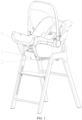
- the infant seat assembly includes a first use mode (see FIG. 1 ) in which the baby carrier 9 can be mounted on the high chair 2, a second use mode (see FIG. 2 ) for use as a dining chair, and a third use mode (see FIG. 3 ) for use as a seat. In the third use mode, the high chair 2 is used as a seat alone. Referring to FIG. 1 , when the infant seat assembly is in the first use mode, the baby carrier 9 is detachably mounted to the high chair 2 by the engaging device 1.
- the high chair 2 includes a seat body 21 and a plurality of support brackets 22 for supporting the seat body 21.
- the seat body 21 includes a carrier base 211, a backrest 212, and two side plates 213.
- the two side plates 213 are connected to two ends of the backrest 212, respectively, and are connected to the carrier base 211.
- the number of the support brackets 22 is four.
- the plurality of support brackets 22 includes two front support brackets 221 and two rear support brackets 222.
- a front link 223 is provided between the two front support brackets 221, and two ends of the front link 223 are connected to the two front support bracket 221 respectively to increase the support stability of the two front support brackets 221.
- a rear link 224 is provided between the two rear support brackets 222, and two ends of the rear link 224 are respectively connected to the two rear support brackets 222 to increase the support stability of the two rear support brackets 222.
- the engaging device 1 includes a first engaging mechanism 12 and an engaging base 11 configured to be connected to the carrier base 211.
- the baby carrier 9 has a crossbar 91 (see FIG. 4 ).
- the first engaging mechanism 12 is movably disposed on the engaging base 11, and the first engaging mechanism 12 is adapted to releasably engage the crossbar 91 with the engaging base 11.
- the crossbar 91 of the baby carrier 9 connects the engaging device 1 to the carrier base 211 of the high chair 2, so that the baby carrier 9 can be easily and stably fixed to the high chair 2, thereby facilitating the care of the infant by the caregiver during the meal, and also facilitating the infant to have a meal with the caregiver.
- the engaging base 11 can be detachably connected to the carrier base 211.
- the lateral cross-section of the engaging base 11 is generally L-shaped.
- An end of the engaging base 11 is provided with a clamping slot 111, and a part of the carrier base 211 can be engaged in the clamping slot 111, so that the engaging base 11 can be conveniently fixed to the carrier base 211.
- the carrier base 211 is in a form of a plate, so as to be engaged in the clamping slot 111. In other embodiments not shown, it is also possible that the carrier base 211 is provided with a clamping slot 111, and an end of the engaging base 11 can be engaged in the clamping slot 111.
- an end of the engaging base 11 may also be detachably connected to the carrier base 211 by bolts.
- an accommodating cavity 112 is formed inside the engaging base 11, so that the first engaging mechanism 12 can be partially accommodated in the accommodating cavity 112.
- the first engaging mechanism 12 includes an unlocking member 121, a first resilient member 122, an indication member 123, an abutting member 124, and a second resilient member 125.
- the unlocking member 121 is pivotally connected to the engaging base 11, and the first resilient member 122 is disposed between the unlocking member 121 and the engaging base 11.
- the unlocking member 121 is switchable between a locked state and an unlocked state.
- the unlocking member 121 has an engaging portion 1211 and a connecting portion 1212. At least a part of the unlocking member 121 is located within the accommodating cavity 112.
- the part of the unlocking member 121 located within the accommodating cavity 112 forms a connecting portion 1212, which is pivotally connected to a cavity wall of accommodating cavity 112.
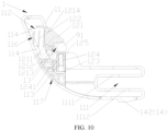
- the engaging portion 1211 is engaged with the crossbar 91, as shown in FIG. 10 .
- the crossbar 91 is disengaged from the engaging portion 1211, as shown in FIG. 8 .
- the unlocking member 121 has a first position and a second position, when the unlocking member 121 is in the first position and in the locked state, the unlocking member is adapted to move from the locked state, via the second position, to the unlocked state; and when the unlocking member 121 is in the first position and in the unlocked state, the unlocking member is adapted to move from the unlocked state, via the second position, to the locked state.
- the second position of the unlocking member 121 is a transition position that the unlocking member 121 needs to pass during the mutual switching between the locked state and the unlocked state.
- the engaging portion 1211 has a first engaging surface 1213 and the engaging base 11 has a second engaging surface 113.
- the first engaging surface 1213 is arranged opposite to the second engaging surface 113, and the first engaging surface 1213 and the second engaging surface 113 are enclosed to form an engaging slot 13.
- the crossbar 91 is adapted to be engaged between the first engaging surface 1213 and the second engaging surface 113, that is, the crossbar 91 is adapted to be engaged in the engaging slot 13.
- the engaging portion 1211 may also be provided with a hook portion, which is adapted to be engaged with the crossbar 91 when the unlocking member 121 is in the first position.
- the engaging portion 1211 has a wedge surface 1214 which is adapted to be pushed against by the crossbar 91, causing the unlocking member 121 to pivot, and the wedge surface 1214 and the first engaging surface 1213 are connected to each other and angularly arranged. In this way, it is possible to push against the unlocking member 121 pivot (see FIG. 9 ) by wedge surface 1214 in the process of the crossbar 91 approaching the engaging base 11 without manual operation of the unlocking member 121, so that the crossbar 91 is capable of being engaged with the engaging portion 1211.
- the first resilient member 122 is adapted to bias the unlocking member 121 to pivot the unlocking member 121 to a first position (i.e., an initial position).
- the crossbar 91 pushes against the wedge surface 1214 in the process of the crossbar 91 approaching the engaging base 11, so as to pivot the unlocking member 121 toward the second position.
- the first resilient member 122 includes a spring. The first resilient member 122 is accommodated within the accommodating cavity 112.
- the cavity wall of the accommodating cavity 112 is provided with a plurality of first projections 114, which are enclosed to form the receiving slot 116.
- An end of the first resilient member 122 abuts against the unlocking member 121 and another end of the first resilient member 122 is inserted into the receiving slot 116 to avoid deflection of the first resilient member 122 during deformation.
- the indication member 123 is movably disposed at the engaging base 11 and is switchable between at least two indication states to indicate the state of unlocking member 121.
- At least two indication states include a first indication state for indicating that the crossbar 91 is disengaged from the first engaging mechanism 12 and a second indication state for indicating that the crossbar 91 is engaged with the first engaging mechanism 12.
- the indication member 123 is provided with indication marks 1232 indicating at least two indication states, respectively.
- the indication marks 1232 includes a red flag to indicate the first indication state and a green flag to indicate the second indication state.
- the indication member 123 is disposed in the accommodating cavity 112, and the engaging base 11 is provided with an indication window117 for displaying any indication mark 1232. Specifically, when the crossbar 91 (see FIG. 4 ) is disengaged from the engaging portion 1211 (that is, when the crossbar 91 is not engaged with the engaging portion 1211), the indication member 123 is in the first indication state, and a red flag of the indication member 123 is located at the indication window 117.
- the indication member 123 When the crossbar 91 is engaged with the engaging portion 1211, the indication member 123 is switched from the first indication state to the second indication state, at which time the green flag of the indication member 123 is moved to the indication window 117. It is thus convenient for the caregiver to determine whether the baby carrier 9 is engaged with the first engaging mechanism 12 based on the indication mark 1232 shown at indication window 117.
- the abutting member 124 is movably disposed on the engaging base 11 and between the unlocking member 121 and the indication member 123. As shown in FIGS. 8 to 10 , the abutting member 124 is switchable between the extended position and the retracted position, and when the abutting member 124 is switched from the extended position to the retracted position, the abutting member 124 pushes the indication member 123, so that the indication member 123 switches from the first indication state to the second indication state.
- An end of abutting member 124 is an abutting end 1241 capable of abutting the crossbar 91. When the abutting member 124 is in the retracted position, as shown in FIG.
- the abutting end 1241 and the second engaging surface 113 are substantially flush, and the crossbar 91 is capable of being engaged between the first engaging surface 1213 and the abutting end 1241.
- the abutting member 124 is in the extended position, as shown in FIG. 8 , the crossbar 91 is disengaged from the first engaging surface 1213.
- the second resilient member 125 is adapted to bias the indication member 123 toward the first indication state.
- An end of the indication member123 has a first driving bevel 1231
- the other end of the abutting member 124 is provided with a second driving bevel 1242 adapted to abut against the first driving bevel 1231 to drive the indication member 123 to move, so that the indication member 123 switches between at least two indicating states (the first indication state and the second indication state in the present embodiment).
- the abutting end 1241 of the abutting member 124 is located between the first engaging surface 1213 and the second engaging surface 113.
- the abutting member 124 is disposed substantially perpendicular to the first engaging surface 1213.
- the abutting member 124 may also be staggered from the first engaging surface 1213.
- the second resilient member 125 is a spring.
- the second resilient member 125 is accommodated within the accommodating cavity 112 and is disposed between the inner walls of the indication member 123 and the engaging base 11.
- the unlocking member 121 is provided with two connecting portions 1212, which are arranged opposite and spaced apart. A part of the indication member 123 and the second resilient member 125 are located between the two connecting portion 1212, and the indication member 123 is movable between the two connecting portions 1212.
- An end of the second resilient member 125 abuts against the indication member 123, and the other end of the second resilient member 125 abuts against the inner wall of the engaging base 11 to bias the indication member 123 toward one of the two connecting portion 1212.
- the engaging device 1 further includes a second engaging mechanism 14, which includes an engaging member 141 and a resilient arm 142.
- the engaging member 141 is connected to the carrier base 211 and forms a mounting groove 15 with the carrier base 211 for insertion of at least part of the engaging base 11.
- the engaging member 141 is provided with a first engaging hole 1411.
- a surface of the carrier base 211 for carrying the infant is the first side surface 2111
- a surface of the carrier base 211 facing away from the first side surface 2111 is the second side surface 2112.
- the engaging member 141 is disposed on the second side surface 2112 of the carrier base 211.
- the resilient arm 142 is connected to the engaging base 11, and the resilient arm 142 is provided with a first engaging projection 1421 capable of being engaged with the first engaging hole 1411.
- the engaging base 11 has an opening groove 118.
- An end of the resilient arm142 is connected to the groove wall of the opening groove 118, and another end of the resilient arm 142 is provided with a first engaging projection 1421.
- the first engaging projection 1421 has an engaged position, in which the first engaging projection 1421 protrudes from the opening groove 118, and a retracted position, in which the first engaging projection 1421 does not protrude from the opening groove 118.
- the first engaging projection 1421 is adapted to be engaged with the first engaging hole 1411.
- the engaging member 141 is capable of pushing against the first engaging projection 1421, so that the first engaging projection 1421 moves to the retracted position, in this case, the resilient arm 142 is elastically deformed.
- the resilient arm 142 is adapted to bias the first engaging projection 1421 to move the first engaging projection 1421 to the engaged position, so that after the engaging base 11 is inserted into the mounting groove 15 in place, the first engaging projection 1421 is capable of being engaged with the first engaging hole 1411 under the elastic deformation of the resilient arm 142.
- the clamping slot 111 includes a first side wall 1112 and a second side wall 1111.
- the second side wall 1111 is adapted to abut against the first side surface 2111, and the first side wall 1112 is adapted to abut against the second side surface 2112.
- the resilient arm 142 is provided on the first side wall 1112.
- the second engaging mechanism 14 it is possible to more firmly connect the engaging base 11 to the carrier base 211, and it is also possible to quickly fix the engaging base 11 to the carrier base 211.
- a specific process of fixedly connecting the engaging device 1 to the baby carrier 9 and the high chair 2, respectively, is as follows: First, as shown in FIG. 11 , after the engaging member 141 is fixed to the carrier base 211, the carrier base 211 is engaged in the clamping slot 111. At this time, as the second side wall 1112 is inserted into the mounting groove 15, the first engaging projection 1421 is engaged in the first engaging hole 1411, so that the engaging device 1 is fixedly connected to the high chair 2.
- the baby carrier 9 is moved toward the carrier base 211, and the crossbar 91 pushes against the wedge surface 1214 of the unlocking member 121 and thus pivots the unlocking member 121 to the second position as the baby carrier 9 approaches the first engaging mechanism 12.
- the crossbar 91 remains abutting against the unlocking member 121 such that the unlocking member 121 remains in the second position while the crossbar 91 pushing the abutting member 124 to move and drives the indication member 123 from the first indication state to the second indication state by the engagement of the second driving bevel 1242 with the first driving bevel 1231.
- the crossbar 91 drives the indication member 123 to move to the second indication state through the abutting member 124, and the crossbar 91 no longer abuts against the wedge surface 1214.
- the unlocking member 121 is pivoted from the second position to the first position under the elastic force of the first resilient member 122, the first engaging surface 1213 is engaged with the crossbar 91, and the unlocking member 121 is in the locked state, so that the crossbar 91 is engaged between the engaging portion 1211 and the abutting member 124.
- the process for disconnecting the engaging device 1 from the baby carrier 9 and the high chair 2 respectively is as follows: First, as shown in FIG. 10 , an external force may be applied to the unlocking member 121 so that it pivots from the first position to the second position, so that the crossbar 91 and the unlocking member 121 are disengaged, thereby disconnecting the baby carrier 9 and the engaging device1, as shown in FIG. 9 .
- the unlocking member 121 When the crossbar 91 is disengaged from the engaging device 1 and the external force applied to the unlocking member 121 is removed, the unlocking member 121 returns from the second position to the first position, that is, the unlocking member 121 returns to the unlocked state (in this case, the unlocking member 121 is in the unlocked state) under the elastic force of the first resilient member 122, as shown in FIG. 8 .
- the indication member 123 moves from the second indication state to the first indication state, and under the engagement of the first driving bevel 1231 and the second driving bevel 1242, the abutting member 124 is driven to move in a direction close to the first engaging surface 1213 until the abutting end 1241 abuts against the first engaging surface 1213, that is, the abutting member 124 moves to the extended position.
- the abutting member 124 when the abutting member 124 is in the extended position, the abutting end 1241 may not abut against the first engaging surface 1213, that is, the abutting end 1241 and the first engaging surface 1213 may be spaced apart.
- the first engaging projection 1421 may exit the first engaging hole 1411 by pressing.
- the clamping slot 111 can be disengaged from the carrier base 211 by an external force applied to the engaging base 11, thereby disconnecting the engaging base 11 and the carrier base 211.
- the infant seat assembly may also include a third engaging mechanism 3, through which the baby carrier 9 can be detachably connected to the backrest 212.
- the third engaging mechanism 3 includes an engaging groove 32, a locking hook member 31, a decorative cover 33, and a third resilient member 34.
- the engaging groove 32 is disposed on the backrest 212.
- a side wall of the engaging groove 32 is provided with a first protruding portion 321, which is spaced apart from a bottom wall 322 of the engaging groove 32 to form a locking hook groove 325.
- the locking hook member 31 is disposed at the baby carrier 9.
- the locking hook member 31 has a hook body 311 adapted to be engaged in the locking hook groove 325 to fix the locking hook member 31 in the engaging groove 32.
- the locking hook member 31 and the crossbar 91 are disposed on a front side and a rear side of the baby carrier 9, respectively.
- the crossbar 91 is disposed on the front side of the baby carrier 9, and the locking hook member 31 is disposed on the rear side of the baby carrier 9.
- the backrest 212 includes a first back plate 2121 and a second back plate 2122 connected to each other.
- the engaging groove 32 includes a first hole portion 32a disposed on the first back plate 2121 and a second hole portion32b disposed on the second back plate 2122.
- a bottom wall 322 of the second hole portion 32b forms a bottom wall of the engaging groove 32.
- a sidewall of the first hole portion 32a protrudes from a sidewall of the second hole portion 32b, so as to form a first protruding portion 321.
- the decorative cover 33 is movably provided in the engaging groove 32, and when the hook body311 (see FIG. 15 ) is not engaged in the locking hook groove 325, the decorative cover 33 is capable of closing a notch of the engaging groove 32.
- the decorative cover 33 has a first end 331 away from the bottom wall 322 of the engaging groove 32 and a second end 332 facing toward the bottom wall 322 of the engaging groove 32.
- the second end 332 is provided with a second protruding portion 333 located between the bottom wall 322 and the first protruding portion 321 of the engaging groove 32.
- the second protruding portion 333 is adapted to abut against the first protruding portion 321 to limit the decorative cover 33 within the engaging groove 32.
- the decorative cover 33 is an integral molding member.
- the first protruding portion 321 is formed by connecting the first back plate 2121 to the second back plate 2122, so that the decorative cover 33 can be conveniently mounted in the engaging groove 32.
- the decorative cover 33 is switchable between a third position and a fourth position.
- the second protruding portion 333 abuts against the first protruding portion 321, and the first end 331 is flush with a surface of backrest 212 to cover the notch of the engaging groove 32.
- the appearance of the high chair 2 can be made neater and more beautiful, and the entrapment can be avoided.
- the decorative cover 33 When the decorative cover 33 is in the fourth position, the first end 331 and the first protruding portion 321 are spaced apart so that the hook body311 is capable of being engaged in the locking hook groove 325, thereby enabling the baby carrier 9 to be fixedly connected to the backrest 212.
- the third resilient member 34 is disposed between the bottom wall 322 of the engaging groove 32 and the decorative cover 33, and the third resilient member 34 is adapted to bias the decorative cover 33, so that the decorative cover 33 moves to the third position.
- the third resilient member 34 includes a spring.
- the bottom wall 322 of the engaging groove 32 may be provided with a third protruding portion 323, which is provided with a receiving hole 324.
- the decorative cover 33 may have a fourth protruding portion 334 disposed facing toward the receiving hole 324.
- An end of the third resilient member 34 is sleeved on the third protruding portion 323, and another end of the third resilient member 34 is inserted into the receiving hole 324 to prevent the third resilient member 34 from shifting during deformation.
- the high chair 2 has a first component and a second component that are relatively movable, and adjusting mechanisms 23a, 23b connected to the first component and the second component, respectively.
- the adjusting mechanisms 23a, 23b are switchable between a locked state and an unlocked state.
- the first component is movable relative to the second component in predetermined directions D1, D2.
- the adjusting mechanisms 23a, 23b are in the locked state, the first component is fixed relative to the second component.
- the first component may be the carrier base 211 and the second component may be the side plate 213.
- the predetermined direction is a direction D1 or a reverse direction of the direction D1 in which the carrier base 211 is away from or close to the backrest 212, that is, the front-rear direction in FIG. 16 .
- the adjusting mechanism may include a first adjusting mechanism 23a.
- the carrier base 211 are connected to the two side plates 213 through the two first adjusting mechanisms 23a, respectively, and movable through the first adjusting mechanism 23a in the direction D1 or in the reverse direction of the direction D1.
- the first adjusting mechanism 23a includes a connecting base 231, a locking member 232, a driving member 233, a fourth resetting member 234, an operating member 235, and a plurality of locking holes 236.
- the operating member 235 abuts against the locking member 232 through the driving member 233 and drives the locking member 232 to move through the driving member 233.
- the fourth resetting member 234 is adapted to bias the locking member 232, so that the locking member 232 returns to an initial position.
- a plurality of locking hole 236 are disposed in one of carrier base 211 (i.e., a first component) and the side plate 213 (i.e., a second component) and arranged in the direction D1.
- the locking member 232 is movably connected to another of the carrier base 211 (i.e., the first component) and the side plate 213 (i.e., the second component).
- the locking member 232 is pivotally connected to the other of the carrier base 211 and the side plate 213.
- a plurality of locking holes 236 are disposed on the side plate 213.
- the locking member 232 is pivotally connected to the carrier base 211.
- the locking member 232 is capable of being inserted into at least one of the plurality of locking holes 236 to releasably and securely connect the carrier base 211 to the side plate 213.
- a first strip groove 2131 is also disposed on the side plate 213.
- a plurality of locking holes 236 are disposed on a bottom wall of the first strip groove 2131 and in communication with the first strip groove 2131.
- a first strip block 2132 is disposed in the first strip groove 2131, the first strip block 2132 is fixed to the bottom wall of the first strip groove 2131, and the plurality of locking holes 236 are evenly distributed on the first strip block 2132.
- the first strip block 2132 having the locking hole 236 is provided in the first strip groove 2131, so that manufacturing can be facilitated.
- an end of the connecting base 231 is movably connected to one of the carrier base 211 and the side plate 213, and the connecting base 231 is fixed to another of the carrier base 211 and the side plate 213.
- the connecting base 231 is movably connected to the side plate 213 and fixedly connected to the carrier base 211.
- the connecting base 231 is fixedly connected to the second side surface 2112 of the carrier base 211 (see FIG. 16 ) to avoid obstructing the infant's ride.
- An end of the connecting base 231 away from the carrier base 211 is movably connected to the side plate 213.
- the connecting base 231 and the carrier base 211 are capable of moving relative to the side plate 213. As shown in FIGS.
- the connecting base 231 has an accommodating groove 2311 for accommodating the locking member 232.
- the accommodating groove 2311 has a side wall 23111 and a bottom wall 23112.
- the bottom wall 23112 of accommodating groove 2311 is arranged opposite to the bottom wall of first strip groove 2131. At least a part of the side wall 23111 of the accommodating groove 2311 is accommodated within the first strip groove 2131 and is movable along the first strip groove 2131.
- the bottom wall 23112 of the accommodating groove 2311 is provided with a strip hole 2312 for the driving member 233 to pass out.
- the locking member 232 includes a locking portion 2321 and a locking body 2322.
- the locking body 2322 is pivotally connected to the connecting base 231 by a pivot shaft 237.
- the locking portion 2321 is disposed at an end of the locking body 2322.
- the locking member 232 is accommodated in the accommodating groove 2311 and is pivotally connected to the side wall 23111 of the accommodating groove 2311 through the pivot shaft 237.
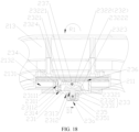
- the locking member 232 is switchable between a locked position and an unlocked position. When the locking member 232 is in the locked position, as shown in FIG. 18 , the locking portion 2321 is capable of extending out of a notch of the accommodating groove 2331 and being inserted into any of the locking holes 236.
- the locking portion 2321 is disengaged from any of the locking holes 236, i.e., the locking portion 2321 exits any of the locking holes 236.
- the locking body 2322 is operable to switch the locking portion 2321 between the locked position and the unlocked position.
- the fourth resetting member 234 is adapted to bias the locking member 232 to pivot to the locked position.
- the driving member 233 includes a driving portion 2332 and an operating portion 2331, and driving portion 2332 abuts against the locking body 2322.
- the operating portion 2331 extends out of the connecting base 231 through the strip hole 2312 to be operated.
- the operating portion 2331 is operable to make the driving portion 2332 push the locking body 2322 to pivot, so as to drive the locking member 232 to switch between the locked position and the unlocked position.
- the operating portion 2331 is movable along the strip hole 2312 and the hole wall of the strip hole 2312 is adapted to abut against the operating portion 2331 to limit the move stroke of the driving member 233.
- a moving direction of the operating portion 2331 is parallel to the direction D1.
- the driving portion 2332 has a first abutting bevel 23321, and the locking body 2322 is provided with a second abutting bevel 2323 arranged opposite to the first abutting bevel 23321.
- the second abutting bevel 2323 and the locking portion 2321 are located on two sides of pivot shaft 237, respectively.
- the driving portion 2332 follows the operating portion 2331 and pushes against the second abutting bevel 2323 through the first abutting bevel 23321, driving the locking member 232 to pivot about the pivot shaft 237.
- the first abutting bevel 23321 is disposed at an angle to the moving direction of the operating portion 2331 and is not perpendicular to the moving direction of the operating portion 2331.
- the moving direction of the operating portion 2331 is parallel to the direction D1.
- a first limiting surface 23221 and a second limiting surface 23222 are formed on a side of the locking body 2322 facing toward the locking hole 236.
- the first limiting surface 23221 and the locking portion 2321 are located on one side of pivot shaft 237, and the second abutting bevel 2323 and the second limiting surface 23222 are located on the other side of the pivot shaft 237.
- the first limiting surface 23221 and the second limiting surface 23222 are arranged at a certain angle, and the specific angle can be set according to actual requirements.
- the locking portion 2321 protrudes from the first limiting surface 23221 so that the locking portion 2321 is capable of extending into the locking hole 236.
- the locking member 232 also includes a projecting portion 2324 for mounting the fourth resetting member 234.
- the projecting portion 2324 is disposed at an end of the locking body 2322 and is disposed opposite to the locking portion 2321. Specifically, the projecting portion 2324 extends away from the locking portion 2321, that is, the projecting portion 2324 extends toward the bottom wall 23112 of the accommodating groove 2311.
- the fourth resetting member 234 includes a spring and is accommodated within the accommodating groove 2311.
- the bottom wall 23112 of the accommodating groove 2311 is provided with a recess 2314.
- An end of the fourth resetting member 234 is inserted into the recess 2314 and the other end of the fourth resetting member 234 is inserted into the projecting portion 2324 to avoid the fourth resetting member 234 offset during pivoting of the locking member 232.
- the operating member 235 is fixed to an end of the operating portion 2331 away from the driving portion 2332, and the operating member 235 is adapted to be operated.
- the operating member 235 is capable of being moved to drive the driving member 233 to move, thereby driving the locking member 232 to pivot.
- the connecting base 231 is provided with a guide groove 2313. A part of the operating member 235 is accommodated in the guide groove 2313 and movable along the guide groove 2313.
- the guide groove 2313 is in communication with the strip hole 2312 and extending in a direction parallel to the first predetermined direction D 1.
- the operating member 235 has an operating surface provided with a non-slip pattern 2351 so as to move the operating member 235 by pushing against the operating surface.
- the direction D1 is a direction toward the backrest 212.
- first adjusting mechanism 23a As shown in FIG. 18 , when the relative positions of the carrier base 211 and the side plate 213 need to be adjusted, the operating member 235 can be pushed in the direction D1, and the operating member 235 drives the driving member 233 to move in the direction D1, and the second abutting bevel 2323 pushes against the first abutting bevel 23321 in the direction D1, so that the locking member 232 pivots toward the R1 direction (counterclockwise in this embodiment) against the elastic force of the fourth resetting member 234.
- the locking portion 2321 is disengaged from one of the plurality of locking holes 236, thereby enabling the carrier base 211 to move relative to the side plate 213.
- the operating member 235 When the carrier base 211 is moved to the desired position, the operating member 235 is released, that is, the external force applied to the operating member 235 is removed, and the locking member 232 pivots in a reverse direction of R1 under the elastic force of the fourth resetting member 234, so that the locking portion 2321 is re-engaged with another of the plurality of locking holes 236, and the driving member 233 is returned to the initial position in the direction D1 by the driving engagement of the first abutting bevel 23321 and the second abutting bevel 2323, thereby driving the operating member 235 to return to the initial position together.
- the high chair 2 further includes a pedal 24 located between two support brackets 22.
- the pedal 24 is movable relative to the two support brackets 22.
- the pedal 24 is movably connected between the two front support brackets 221.
- the first component may be the support bracket 22 and the second component may be the pedal 24.
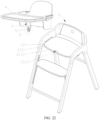
- the predetermined direction is the direction D2 or the reverse direction of the direction D2 in which the pedal 24 is relatively away from or close to the carrier base 211, that is, the up-down direction in FIG. 21 .
- the adjusting mechanism includes a second adjusting mechanism 23b.
- the pedal 24 is connected to two support brackets 22 through two second adjusting mechanisms 23b respectively and movable through the second adjusting mechanism 23b in the second predetermined direction D2.
- the structures of the second adjusting mechanism 23b and the first adjusting mechanism 23a are substantially identical, and each includes a connecting base 231, a locking member 232, a driving member 233, a fourth resetting member 234, an operating member 235, and a plurality of locking holes 236.
- the second adjusting mechanism 23b differs from the first adjusting mechanism 23a in that the connecting base 231 of the second adjusting mechanism 23b is fixedly connected to the pedal 24 and movably connected to the support bracket 22, and a plurality of locking holes 236 are provided on the support bracket 22 so that the pedal 24 can be releasably connected to the support bracket 22.
- a second strip groove 225 is disposed on the support bracket 22.
- a part of the connecting base 231 is accommodated within and movable along the second strip groove 225.
- a second strip block 226 is provided in the second strip groove 225, and the second strip block 226 is fixedly connected to the bottom wall of the second strip groove 225.
- a plurality of locking holes 236 are provided on the second strip block 226 and in communication with the second strip groove 225.
- the infant seat assembly further includes a dinner plate 4 and a blocking member 5.
- the blocking member 5 is capable of limiting the infant to the carrier base 211 of the high chair 2, and prevent the infant from accidentally falling out of the gap between the dinner plate 4 and the carrier base 211.
- the engaging device 1 is not connected to the high chair 2 when the infant seat assembly is in the second use mode.
- An end of the blocking member 5 is connected to the dinner plate 4 and the other end of the blocking member 5 is detachably connected to the carrier base 211.
- the other end of the blocking member 5 is provided with a resilient finger 51.
- An end of the resilient finger 51 is a free end 513 and extends toward the dinner plate 4.
- the resilient finger 51 has a second engaging projection 511, and the carrier base 211 has a second engaging hole 2113 disposed therethrough.
- the second engaging projection 511 passes through the carrier base 211 through the second engaging hole 2113 and abuts against an end face of the carrier base 211 opposite to the dinner plate 4 (i.e., the second side surface 2112 of the carrier base 211), so as to be detachably connected to the carrier base 211.
- the resilient finger 51 also has an operating projection 512 disposed close to the free end 513 relative to the second engaging projection 511, and the operating projection 512 is depressible.
- the operating projection 512 is located between the dinner plate 4 and the first side surface 2111 of the carrier base, so as to facilitate pressing of the operating projection 512.
- the blocking member 5 also has a limiting projection 52 capable of abutting the first side surface 2111 of the carrier base 211 to prevent the dinner plate 4 from moving excessively toward the carrier base 211.
- the resilient finger 51 is deformed by pressing the resilient finger 51 (specifically, the operating projection 512 of the resilient finger 51), so that the second engaging projection 511 and the second side surface 2112 is disengaged from each other, whereby the blocking member 5 can be removed from the second engaging hole 2113, so that the dinner plate 4 and the blocking member 5 can be removed.
- the engaging device 1 and the infant seat assembly have at least the following technical effects: By connecting the engaging device 1 to the crossbar 91 of the baby carrier 9 and the carrier base 211 of the high chair 2, respectively, the baby carrier 9 can be easily and stably fixed to the high chair 2, so that a caregiver can conveniently and stably take care of an infant while eating a meal, and the infant can also conveniently share a meal with the caregiver.
- the carrier base 211 is slidable with respect to the side plate 213 to adjust the seating space of the high chair 2 (i.e., a space formed by enclosing the carrier base 211, the backrest 212, the side plate 213, and the like), so that the carrier base 211 can be applied to children of different sizes or ages, and the carrier base 211 can be adapted to mount baby carrier 9 of different sizes.
- the baby carrier can be easily and stably fixed to the high chair, thereby facilitating the care of the infant by the caregiver during the meal, and facilitating the infant to have a meal with the caregiver.
Landscapes
- Engineering & Computer Science (AREA)
- General Engineering & Computer Science (AREA)
- Mechanical Engineering (AREA)
- Health & Medical Sciences (AREA)
- General Health & Medical Sciences (AREA)
- Pediatric Medicine (AREA)
- Carriages For Children, Sleds, And Other Hand-Operated Vehicles (AREA)
Abstract
An engaging device (1) and an infant seat assembly having the engaging device (1). The engaging device (1) is adapted to fix the baby carrier (9) to the high chair (2), the baby carrier (9) has a crossbar (91) and the high chair (2) has a carrier base (211). The engaging device (1) includes an engaging base (11) and a first engaging mechanism (12). The engaging base (11) is adapted to be connected to the carrier base (211). The first engaging mechanism (12) is movably disposed on the engaging base (11). The first engaging mechanism (12) is adapted to releasably engage the crossbar (91) with the engaging base (11). The infant seat assembly includes a high chair (2) and the aforementioned engaging device (1). The baby basket can be detachably mounted to the carrier base (211) of the high chair (2) by the engaging device (1).
Description
- The present disclosure relates to the technical field of infant carrier, and more particularly, to an engaging device and an infant seat assembly having the engaging device.
- Children high chairs are generally used by infants when eating with adults at the table. The high chair on the market realizes switching between different use modes by mounting different seats thereon, thereby meeting the use requirements of infants of different ages and prolonging the use time of the high chair. However, at present, the high chair on the market cannot be engaged to the baby carrier, and it is difficult to fix the baby carrier to the high chair conveniently and quickly.
- Accordingly, the present disclosure provides an engaging device which is capable of being detachably connected to a baby carrier and a high chair, respectively, so that the baby carrier can be conveniently and quickly fixed to the high chair.
- According to one aspect of the present disclosure, an engaging device adapted to fix a baby carrier to a high chair is provided, the baby carrier has a crossbar and the high chair has a carrier base.
- The engaging device includes an engaging base and a first engaging mechanism. The engaging base is adapted to be connected to the carrier base. The first engaging mechanism is movably disposed on the engaging base. The first engaging mechanism is adapted to releasably engage with the crossbar to the engaging base.
- In one of the embodiments, the first engaging mechanism includes an unlocking member movably connected to the engaging base and switchable between a locked state and an unlocked state. The unlocking member has an engaging portion. When the unlocking member is in a locked state, the engaging portion is engaged with the crossbar, and when the unlocking member is in the unlocked state, the crossbar is disengaged from the engaging portion.
- In one of the embodiments, an accommodating cavity is formed inside the engaging base. At least a part of the unlocking member is located within the accommodating cavity. A part of the unlocking member located within the accommodating cavity has a connecting portion. The connecting portion is pivotally connected to a cavity wall of the accommodating cavity. The engaging portion is capable of extending beyond the accommodating cavity to be engaged with the crossbar.
- In one of the embodiments, the engaging portion has a first engaging surface and the engaging base has a second engaging surface. When the unlocking member is in a locked state, the first engaging surface and the second engaging surface are arranged opposite to each other, and the crossbar is engaged between the first engaging surface and the second engaging surface.
- In one of the embodiments, the unlocking member is movably connected to the engaging base, the engaging portion has a wedge surface adapted to be pushed against by the crossbar to enable the unlocking member to move.
- In one of the embodiments, the engaging portion has a first engaging surface, when the unlocking member is in the unlocked state, the crossbar is engaged between the first engaging surface and the engaging base, and the wedge surface and the first engaging surface are connected to each other and are angularly arranged.
- In one of the embodiments, the unlocking member has a first position and a second position, when the unlocking member is in the first position and in the locked state, the unlocking member is adapted to move from the locked state, via the second position, to the unlocked state; when the unlocking member is in the first position and in the unlocked state, the unlocking member is adapted to move from the unlocked state, via the second position, to the locked state.
- In one of the embodiments, the engaging portion has a wedge surface, the wedge surface is adapted to be pushed against by the crossbar to enable the unlocking member to move from the first position to the second position.
- In one of the embodiments, the first engaging mechanism further includes a first resilient member, the first resilient member is arranged between the unlocking member and the engaging base, the first resilient member is adapted to bias the unlocking member to cause the unlocking member to move to the first position.
- In one of the embodiments, the first engaging mechanism further includes an indication member. The indication member is movably disposed at the engaging base and switchable between at least two indication states to indicate an engaged state or a disengaged state of the unlocking member with the crossbar.
- In one of the embodiments, the indication member is provided with indication marks indicating at least two indication states, respectively, an accommodating cavity is formed inside the engaging base, the indication member is disposed in the accommodating cavity, and the engaging base is provided with an indication window for displaying any of the indication marks.
- In one of the embodiments, the at least two indication states include a first indication state for indicating that the crossbar is disengaged from the first engaging mechanism and a second indication state for indicating that the crossbar is engaged with the first engaging mechanism.
- In one of the embodiments, the first engaging mechanism further includes a second resilient member adapted to bias the indication member toward the first indication state.
- In one of the embodiments, the first engaging mechanism includes an abutting member movably disposed on the engaging base and switchable between at least two indication states.
- In one of the embodiments, the abutting member is switchable between an extended position and a retracted position. When the abutting member is switched from the extended position to the retracted position, the abutting member pushing the indication member to switch from a first indication state for indicating that the crossbar is disengaged from the first engaging mechanism to a second indication state for indicating that the crossbar is engaged with the first engaging mechanism.
- In one of the embodiments, the indication member has a first driving bevel and an end of the abutting member is provided with a second driving bevel adapted to abut against the first driving bevel to drive the indication member to switch between the at least two indication states.
- In one of the embodiments, the abutting member is switchable between an extended position and a retracted position. When the abutting member is in the retracted position, the crossbar is capable of being engaged between the first engaging surface and the abutting member. When the abutting member is in the extended position, the crossbar is disengaged from the first engaging surface.
- In one of the embodiments, another end of the abutting member is an abutting end abutting against the crossbar to enable the crossbar to drive the abutting member to switch from the extended position to the retracted position.
- In one of the embodiments, the engaging device further includes a second engaging mechanism. The second engaging mechanism includes an engaging member, a resilient arm and a first engaging projection. The engaging member is connected to the carrier base and provided with a first engaging hole. The resilient arm is connected to the engaging base. The first engaging projection is disposed on the resilient arm and is adapted to be engaged with the first engaging hole.
- In one of the embodiments, the engaging member and the carrier base form a mounting groove for mounting at least a part of the engaging base. When at least a part of the engaging base is inserted into the mounting groove, the resilient arm enters the mounting groove and the first engaging projection is engaged with the first engaging hole.
- In one of the embodiments, the engaging base has an opening groove. An end of the resilient arm is connected to a groove wall of the opening groove. The first engaging projection has an engaged position, in which the first engaging projection protrudes from the opening groove; and a retracted position, in which the first
engaging projection 1421 does not protrude from theopening groove 118. When the first engaging projection is in the engaged position, the first engaging projection is adapted to be engaged with the first engaging hole. When the engaging base is inserted into the mounting groove, the engaging member is capable of pushing the first engaging projection to move to the retracted position. The resilient arm is adapted to bias the first engaging projection to move the first engaging projection to the engaged position. - In one of the embodiments, the engaging base is provided with a clamping slot. When the first engaging projection is engaged with the first engaging hole, at least a part of the carrier base is inserted into the clamping slot.
- In one of the embodiments, the engaging base is provided with a clamping slot having a first side wall. The opening groove is provided on the first side wall. The engaging member and the carrier base form a mounting groove for insertion of the engaging base. When at least a part of the engaging base is inserted into the mounting groove, at least a part of the carrier base is inserted into the clamping slot, and the first engaging projection is engaged with the first engaging hole.
- According to another aspect of the present disclosure an infant seat assembly including a high chair and the aforementioned engaging device is provided. A baby carrier is adapted to be detachably mounted to the carrier base of the high chair by the engaging device.
- In one of the embodiments, the infant seat assembly further includes a third engaging mechanism. The high chair further includes a backrest. The baby carrier is adapted to be detachably connected to the backrest by the third engaging mechanism.
- In one of the embodiments, the first engaging mechanism includes an engaging groove and a locking hook member. The engaging groove is disposed on the backrest. A side wall of the engaging groove is provided with a first protruding portion that is spaced apart from a bottom wall of the engaging groove to form a locking hook groove. The locking hook member is disposed on the baby carrier. The locking hook member has a hook body adapted to be engaged in the locking hook groove to fix the locking hook member in the engaging groove.
- In one of the embodiments, the third engaging mechanism further includes a decorative cover movably disposed on the engaging groove. The decorative cover is adapted to cover a notch of the engaging groove when the hook body is not engaged with the locking hook groove.
- In one of the embodiments, the decorative cover has a first end away from the bottom wall of the engaging groove and a second end facing toward the bottom wall of the engaging groove. The second end is provided with a second protruding portion. The second protruding portion is located between the bottom wall of the engaging groove and the first protruding portion. The decorative cover is switchable between a third position and a fourth position. When the decorative cover is located in the third position, the first end is flush with a surface of the backrest and the second protruding portion abuts against the first protruding portion. When the decorative cover is in the fourth position, the second protruding portion and the first protruding portion are spaced apart so that the hook body is capable of being engaged in the locking hook groove.
- In one of the embodiments, the third engaging mechanism further includes a third resilient member disposed between the bottom wall of the engaging groove and the decorative cover. The third resilient member is adapted to bias the decorative cover to move to the third position.
- In one of the embodiments, the high chair has a first component and a second component that are relatively movable, and an adjusting mechanism connected to the first component and the second component, respectively. The adjusting mechanism is switchable between a locked state and an unlocked state. When the adjusting mechanism is in the unlocked state, the first component is movable in a predetermined direction relative to the second component. When the adjusting mechanism is in a locked state, the first component is fixed relative to the second component.
- In one of the embodiments, the adjusting mechanism includes a plurality of locking holes and a locking member. The plurality of locking holes is disposed in one of the first component and the second component and arranged in the predetermined direction. The locking member is movably connected to another of the first component and the second component. The locking member includes a locking portion and is switchable between a locked position and an unlocked position. The locking portion is inserted into any of the locking holes when the locking member is in the locked position, and the locking portion is disengaged from any of the plurality of locking holes when the locking member is in the unlocked lock position.
- In one of the embodiments, the locking member further includes a locking body pivotally connected to the other of the first component and the second component by a pivot shaft. The locking portion is disposed at an end of the locking body, and the locking body is operable to switch the locking portion between the locked position and the unlocked position.
- In one of the embodiments, the adjusting mechanism further includes a driving member. The driving member includes a driving portion and an operating portion. The driving portion abuts against the locking body, and the operating portion is operable to cause the driving portion to push the locking body to pivot.
- In one of the embodiments, the adjusting mechanism further includes a driving member. The driving member includes a driving portion and an operating portion. The driving portion has a first abutting bevel. The locking body is provided with a second abutting bevel opposite to the first abutting bevel, and the operating portion being operable to cause the second abutting bevel to push against the first abutting bevel, causing the locking member to pivot.
- In one of the embodiments, the adjusting mechanism further includes a fourth resetting member adapted to bias the locking member to pivot toward the locked position.
- In one of the embodiments, the infant seat assembly further includes a connecting base fixed to the other of the first component and the second component. The connecting base is provided with an accommodating groove. The locking member is movably disposed in the accommodating groove. The locking portion is adapted to extend out of a notch of the accommodating groove to be inserted into any of the locking holes.
- In one of the embodiments, the adjusting mechanism further includes a driving member. The driving member includes a driving portion and an operating portion. The driving portion abuts against the locking member. The bottom wall of the accommodating groove is provided with a strip hole. The operating portion extends out of the connecting base through the strip hole to be operated. The operating portion is operable to cause the driving portion to drive the locking member to switch between a locked position and an unlocked position.
- In one of the embodiments, the adjusting mechanism further includes an operating member fixed to an end of the operating portion away from the driving portion, and the operating member is adapted to be operated.
- In one of the embodiments, the one of the first component and the second component is provided with a strip slot. The plurality of locking holes is provided on a bottom wall of the strip slot, and at least a part of the connecting base is accommodated in and movable along the strip slot.
- In one of the embodiments, the high chair includes a backrest and two side plates connected to two ends of the backrest, respectively. The carrier base is located between the two side plates and movable relative to the two side plates. The first component includes the carrier base, and the second component includes the side plate.
- In one of the embodiments, the high chair includes a seat body, a plurality of support brackets for supporting the seat body, and a pedal located between two of the support brackets. The pedal is movable relative to the two support brackets. The first component includes the support bracket, and the second component includes the pedal.
- In one of the embodiments, the infant seat assembly further includes a dinner plate and a blocking member. An end of the blocking member is connected to the dinner plate and another end of the blocking member is detachably connected to the carrier base.
- In one of the embodiments, the other end of the blocking member is provided with a resilient finger. The resilient finger has a second engaging projection. The carrier base has a second engaging hole disposed therethrough. The second engaging projection is adapted to pass through the carrier base via the second engaging hole and abut against an end surface of the carrier base opposite to the dinner plate.
-
-
FIG. 1 is a schematic structural diagram of an infant seat assembly in a first use mode in which a baby carrier is fixed to a high chair according to an embodiment of the present disclosure; -
FIG. 2 is a schematic structural diagram of the infant seat assembly in a second use mode according to an embodiment of the present disclosure; -
FIG. 3 is a schematic structural diagram of the infant seat assembly in a third use mode according to an embodiment of the present disclosure; -
FIG. 4 is a schematic structural diagram of the infant seat assembly and the baby carrier according to an embodiment of the present disclosure; -
FIG. 5 is a schematic structural diagram of an engaging device according to an embodiment of the present disclosure; -
FIG. 6 is a schematic structural diagram of the engaging device inFIG. 5 in another view; -
FIG. 7 is a schematic structural diagram of the engaging device ofFIG. 5 in yet another view, showing that the engaging base is hidden; -
FIG. 8 is a cross-sectional view of the engaging device inFIG. 5 with an unlocking member in a first position and an indication member in a first indication state; -
FIG. 9 is a cross-sectional view of the engaging device inFIG. 5 with the unlocking member in a second position and the indication member in the first indicated state; -
FIG. 10 is a cross-sectional view of the engaging device inFIG. 5 with the unlocking member in the first position and the indication member in a second indication state; -
FIG. 11 is a partial schematic diagram of the engaging device connected to carrier base according to an embodiment of the present disclosure; -
FIG. 12 is a cross-sectional view of the engaging device inFIG. 5 in another view; -
FIG. 13 is a cross-sectional view of the infant seat assembly ofFIG. 4 ; -
FIG. 14 is an enlarged view of portion A inFIG. 13 with decorative cover in a third position; -
FIG. 15 is a schematic structural diagram of the baby carrier inFIG. 4 in another view; -
FIG. 16 is a schematic structural diagram of a high chair according to an embodiment of the present disclosure; -
FIG. 17 is an enlarged view of portion B inFIG. 16 ; -
FIG. 18 is a partial cross-sectional view of a first adjusting mechanism of the high chair according to an embodiment of the present disclosure, showing the first adjusting mechanism at a locked state; -
FIG. 19 is a partial cross-sectional view of the first adjusting mechanism of the high chair inFIG. 18 , showing the first adjusting mechanism in an unlocked state; -
FIG. 20 is an enlarged view of portion C inFIG. 15 ; -
FIG. 21 is a partial cross-sectional view of a second adjusting mechanism of the high chair according to an embodiment of the present disclosure, showing the second adjusting mechanism at a locked state; -
FIG. 22 is an exploded view of the seat assembly ofFIG. 2 ; and -
FIG. 23 is an enlarged view of portion D inFIG. 22 . -
- 1: engaging device; 11: engaging base; 111: clamping slot; 1111: second side wall: 1112: first side wall; 112: accommodating cavity; 113: second engaging surface; 114: first projection; 116: receiving slot; 117: indication window; 118: opening groove; 12: first engaging mechanism; 121: unlocking member; 1211: engaging portion; 1212: connecting portion; 1213: first engaging surface; 1214: wedge surface; 122: first resilient member; 123: indication member; 1231: first driving bevel; 1232: indication mark; 124: abutting member; 1241: abutting end; 1242: second driving bevel; 125: second resilient member; 13: engaging slot; 14: second engaging mechanism; 141: engaging member; 1411: first engaging hole; 142: resilient arm; 1421: first engaging projection; 15: mounting groove ;
- 2: high chair; 21: seat body; 211: carrier base; 2111: first side surface; 2112: second side surface; 2113: second engaging hole; 212: backrest; 2121: first back plate; 2122: second back plate; 213: side plate; 2131: first strip groove; 2132: first strip block; 22: support bracket; 221: front support bracket; 222: rear support bracket; 223: front cross bar; 224: rear cross bar; 225: second strip groove; 226: second strip block; 23a: first adjusting mechanism; 231: connecting base; 2311: accommodating groove; 23111: side wall of the accommodating groove; 23112: bottom wall of the accommodating groove; 2312: strip hole; 2313: guide groove; 2314: recess; 232: locking member; 2321: locking portion; 2322: locking body; 2322c: third segment; 23221: first limiting surface; 23222: second limiting surface; 2323: second abutting bevel; 2324: projecting portion; 233: driving member; 2331: operating portion; 2332: driving portion; 23321: first abutting bevel; 234: fourth resetting member; 235: operating member; 2351: non-slip pattern; 236: locking hole; 237: pivot shaft; 23b: second adjusting mechanism; 24: pedal;
- 3: third engaging mechanism; 31: locking hook member; 311: hook body; 32: engaging groove; 32a: first hole portion; 32b: second hole portion; 321: first protruding portion; 322: bottom wall of the engaging groove; 323: third protruding portion; 324: receiving hole; 325: locking hook groove; 33: decorative cover; 331: first end; 332: second end; 333: second protruding portion; 334: fourth protruding portion; 34: third resilient member;
- 4: dinner plate;
- 5: blocking member; 51: resilient finger; 511: second engaging projection; 512: operating projection; 52: limiting projection;
- 9: baby carrier; and 91: crossbar.
- The above objects, features, and advantages of the present invention will become more apparent by describing in detail embodiments thereof with reference to the accompanying drawings. In the following description, numerous specific details are set forth in order to provide a thorough understanding of the present disclosure. However, the present disclosure can be implemented in many other ways than those described herein, and such modifications may be made by those skilled in the art without departing from the scope of the disclosure, which is therefore not to be limited to the specific embodiments disclosed below.
- In the description of the present disclosure, it should be understood that the terms "center", "longitudinal", "lateral", "length", "width", "thickness", "upper", "lower", "front", "back", "left", "right", "vertical", "horizontal", "top", "bottom", "inner", "outer", "clockwise", "counterclockwise", "axial", "radial", "circumferential" and other indicated orientations or positional relationships are based on the orientations or positional relationships shown in the accompanying drawings, and are only for the convenience of describing the present disclosure and simplifying the description, rather than for indicating or implying that the indicated device or elements must have a particular orientation, or constructing and operating in a particular orientation, and are therefore not to be construed as limitations of the present disclosure.
- In addition, the terms "first" and "second" are only used for descriptive purposes, and should not be construed as indicating or implying relative importance or implying the number of indicated technical features. Thus, features delimited with "first" or "second" may expressly or implicitly include at least one of these features. In the description of the present disclosure, "plurality" means at least two, such as two, three, etc., unless otherwise expressly and specifically defined.
- In the present disclosure, unless otherwise expressly specified and limited, the terms "mounted", "connected to each other", "connected", "fixed" and other terms should be understood in a broad sense, for example, it may be a fixed connection or a detachable connection, or integrated; it can be a mechanical connection or an electrical connection; it can be directly connected or indirectly connected through an intermediate medium, it can be an internal connection of two elements or the interaction relationship between the two elements, unless otherwise specified limit. For those of ordinary skill in the art, the specific meanings of the above terms in the present disclosure can be understood according to specific situations.
- In the present disclosure, unless otherwise expressly specified and limited, a first feature "on" or "under" a second feature may be the first feature is in direct contact with the second feature, or the first feature is in indirect contact with the second feature. Also, the first feature is "above", "over" and "on" the second feature may mean that the first feature is directly above or obliquely above the second feature, or simply means that the first feature has a higher level than the second feature. The first feature being "below", "beneath" and "under" the second feature may mean that the first feature is directly or obliquely below the second feature, or simply means that the first feature has a lower level than the second feature.
- It should be noted that when an element is referred to as being "fixed to" or "disposed on" another element, it can be directly on the other element or an intervening element may also be present. When an element is considered to be "connected to" another element, it can be directly connected to another element or indirectly connected to another element with a mediating element. The terms "vertical", "horizontal", "up", "down". "left", "right" and similar expressions used herein are for illustrative purposes only and are not intended to be the only means of implementation.
- An embodiment according to the present disclosure provides an
engaging device 1 and an infant seat assembly having the engagingdevice 1. As shown inFIGS. 1 to 3 , the infant seat assembly includes ahigh chair 2 and anengaging device 1. The infant seat assembly has a variety of modes of use to accommodate the use needs of infants of different ages. The engagingdevice 1 is adapted to fix the baby carrier 9 to thehigh chair 2. The infant seat assembly includes a first use mode (seeFIG. 1 ) in which the baby carrier 9 can be mounted on thehigh chair 2, a second use mode (seeFIG. 2 ) for use as a dining chair, and a third use mode (seeFIG. 3 ) for use as a seat. In the third use mode, thehigh chair 2 is used as a seat alone. Referring toFIG. 1 , when the infant seat assembly is in the first use mode, the baby carrier 9 is detachably mounted to thehigh chair 2 by the engagingdevice 1. - As shown in
FIG. 4 , thehigh chair 2 includes aseat body 21 and a plurality ofsupport brackets 22 for supporting theseat body 21. Theseat body 21 includes acarrier base 211, abackrest 212, and twoside plates 213. The twoside plates 213 are connected to two ends of thebackrest 212, respectively, and are connected to thecarrier base 211. In this embodiment, the number of thesupport brackets 22 is four. Specifically, the plurality ofsupport brackets 22 includes twofront support brackets 221 and tworear support brackets 222. Afront link 223 is provided between the twofront support brackets 221, and two ends of thefront link 223 are connected to the twofront support bracket 221 respectively to increase the support stability of the twofront support brackets 221. Similarly, arear link 224 is provided between the tworear support brackets 222, and two ends of therear link 224 are respectively connected to the tworear support brackets 222 to increase the support stability of the tworear support brackets 222. - In some embodiments, as shown in
FIG. 5 , the engagingdevice 1 includes a first engagingmechanism 12 and an engagingbase 11 configured to be connected to thecarrier base 211. The baby carrier 9 has a crossbar 91 (seeFIG. 4 ). The first engagingmechanism 12 is movably disposed on the engagingbase 11, and the first engagingmechanism 12 is adapted to releasably engage thecrossbar 91 with the engagingbase 11. Thecrossbar 91 of the baby carrier 9 connects the engagingdevice 1 to thecarrier base 211 of thehigh chair 2, so that the baby carrier 9 can be easily and stably fixed to thehigh chair 2, thereby facilitating the care of the infant by the caregiver during the meal, and also facilitating the infant to have a meal with the caregiver. - As shown in
FIGS. 5 ,6 and11 , the engagingbase 11 can be detachably connected to thecarrier base 211. The lateral cross-section of the engagingbase 11 is generally L-shaped. An end of the engagingbase 11 is provided with aclamping slot 111, and a part of thecarrier base 211 can be engaged in theclamping slot 111, so that the engagingbase 11 can be conveniently fixed to thecarrier base 211. Thecarrier base 211 is in a form of a plate, so as to be engaged in theclamping slot 111. In other embodiments not shown, it is also possible that thecarrier base 211 is provided with aclamping slot 111, and an end of the engagingbase 11 can be engaged in theclamping slot 111. In other embodiments not shown, an end of the engagingbase 11 may also be detachably connected to thecarrier base 211 by bolts. Referring toFIG. 8 , anaccommodating cavity 112 is formed inside the engagingbase 11, so that the first engagingmechanism 12 can be partially accommodated in theaccommodating cavity 112. - Specifically, as shown in
FIGS. 7 to 9 , the first engagingmechanism 12 includes an unlockingmember 121, a firstresilient member 122, anindication member 123, an abuttingmember 124, and a secondresilient member 125. The unlockingmember 121 is pivotally connected to the engagingbase 11, and the firstresilient member 122 is disposed between the unlockingmember 121 and the engagingbase 11. The unlockingmember 121 is switchable between a locked state and an unlocked state. The unlockingmember 121 has an engagingportion 1211 and a connectingportion 1212. At least a part of the unlockingmember 121 is located within theaccommodating cavity 112. The part of the unlockingmember 121 located within theaccommodating cavity 112 forms a connectingportion 1212, which is pivotally connected to a cavity wall of accommodatingcavity 112. When the unlockingmember 121 is in the locked state, the engagingportion 1211 is engaged with thecrossbar 91, as shown inFIG. 10 . When the unlockingmember 121 is in the unlocked state, thecrossbar 91 is disengaged from the engagingportion 1211, as shown inFIG. 8 . In this embodiment, the unlockingmember 121 has a first position and a second position, when the unlockingmember 121 is in the first position and in the locked state, the unlocking member is adapted to move from the locked state, via the second position, to the unlocked state; and when the unlockingmember 121 is in the first position and in the unlocked state, the unlocking member is adapted to move from the unlocked state, via the second position, to the locked state. The second position of the unlockingmember 121, as shown inFIG. 9 , is a transition position that the unlockingmember 121 needs to pass during the mutual switching between the locked state and the unlocked state. - Specifically, the engaging
portion 1211 has a firstengaging surface 1213 and the engagingbase 11 has a secondengaging surface 113. When the unlockingmember 121 is in the first position, the firstengaging surface 1213 is arranged opposite to the secondengaging surface 113, and the firstengaging surface 1213 and the secondengaging surface 113 are enclosed to form an engagingslot 13. Thecrossbar 91 is adapted to be engaged between the firstengaging surface 1213 and the secondengaging surface 113, that is, thecrossbar 91 is adapted to be engaged in the engagingslot 13. In other embodiments not shown, the engagingportion 1211 may also be provided with a hook portion, which is adapted to be engaged with thecrossbar 91 when the unlockingmember 121 is in the first position. In the present embodiment, further, the engagingportion 1211 has awedge surface 1214 which is adapted to be pushed against by thecrossbar 91, causing the unlockingmember 121 to pivot, and thewedge surface 1214 and the firstengaging surface 1213 are connected to each other and angularly arranged. In this way, it is possible to push against the unlockingmember 121 pivot (seeFIG. 9 ) bywedge surface 1214 in the process of thecrossbar 91 approaching the engagingbase 11 without manual operation of the unlockingmember 121, so that thecrossbar 91 is capable of being engaged with the engagingportion 1211. - As shown in
FIGS. 8 to 10 , the firstresilient member 122 is adapted to bias the unlockingmember 121 to pivot the unlockingmember 121 to a first position (i.e., an initial position). Thecrossbar 91 pushes against thewedge surface 1214 in the process of thecrossbar 91 approaching the engagingbase 11, so as to pivot the unlockingmember 121 toward the second position. When thecrossbar 91 continues to move to the engagingslot 13, thecrossbar 91 no longer pushes against thewedge surface 1214, and the unlockingmember 121 pivots from the second position to the first position under the elastic force of the firstresilient member 122. In this embodiment, the firstresilient member 122 includes a spring. The firstresilient member 122 is accommodated within theaccommodating cavity 112. The cavity wall of theaccommodating cavity 112 is provided with a plurality offirst projections 114, which are enclosed to form the receivingslot 116. An end of the firstresilient member 122 abuts against the unlockingmember 121 and another end of the firstresilient member 122 is inserted into the receivingslot 116 to avoid deflection of the firstresilient member 122 during deformation. - As shown in
FIGS. 6 to 8 , theindication member 123 is movably disposed at the engagingbase 11 and is switchable between at least two indication states to indicate the state of unlockingmember 121. At least two indication states include a first indication state for indicating that thecrossbar 91 is disengaged from the first engagingmechanism 12 and a second indication state for indicating that thecrossbar 91 is engaged with the first engagingmechanism 12. As shown inFIG. 11 , theindication member 123 is provided withindication marks 1232 indicating at least two indication states, respectively. The indication marks 1232 includes a red flag to indicate the first indication state and a green flag to indicate the second indication state. Of course, in other embodiments, at least two other different indication marks may be used to indicate at least two states as long as different indication states can be distinguished. In this embodiment, theindication member 123 is disposed in theaccommodating cavity 112, and the engagingbase 11 is provided with an indication window117 for displaying anyindication mark 1232. Specifically, when the crossbar 91 (seeFIG. 4 ) is disengaged from the engaging portion 1211 (that is, when thecrossbar 91 is not engaged with the engaging portion 1211), theindication member 123 is in the first indication state, and a red flag of theindication member 123 is located at theindication window 117. When thecrossbar 91 is engaged with the engagingportion 1211, theindication member 123 is switched from the first indication state to the second indication state, at which time the green flag of theindication member 123 is moved to theindication window 117. It is thus convenient for the caregiver to determine whether the baby carrier 9 is engaged with the first engagingmechanism 12 based on theindication mark 1232 shown atindication window 117. - As shown in
FIG. 7 , the abuttingmember 124 is movably disposed on the engagingbase 11 and between the unlockingmember 121 and theindication member 123. As shown inFIGS. 8 to 10 , the abuttingmember 124 is switchable between the extended position and the retracted position, and when the abuttingmember 124 is switched from the extended position to the retracted position, the abuttingmember 124 pushes theindication member 123, so that theindication member 123 switches from the first indication state to the second indication state. An end of abuttingmember 124 is anabutting end 1241 capable of abutting thecrossbar 91. When the abuttingmember 124 is in the retracted position, as shown inFIG. 9 , theabutting end 1241 and the secondengaging surface 113 are substantially flush, and thecrossbar 91 is capable of being engaged between the firstengaging surface 1213 and theabutting end 1241. When the abuttingmember 124 is in the extended position, as shown inFIG. 8 , thecrossbar 91 is disengaged from the firstengaging surface 1213. The secondresilient member 125 is adapted to bias theindication member 123 toward the first indication state. An end of the indication member123 has afirst driving bevel 1231, the other end of the abuttingmember 124 is provided with asecond driving bevel 1242 adapted to abut against thefirst driving bevel 1231 to drive theindication member 123 to move, so that theindication member 123 switches between at least two indicating states (the first indication state and the second indication state in the present embodiment). When the unlockingmember 121 is in the unlocked state in the first position, theabutting end 1241 of the abuttingmember 124 is located between the firstengaging surface 1213 and the secondengaging surface 113. In this embodiment, when the unlockingmember 121 is in the unlocked state in the first position, the abuttingmember 124 is disposed substantially perpendicular to the firstengaging surface 1213. Of course, in other embodiments, the abuttingmember 124 may also be staggered from the firstengaging surface 1213. - As shown in
FIGS. 9 and10 , when thecrossbar 91 moves to be engaged with the engagingportion 1211, thecrossbar 91 pushes against theabutting end 1241 of the abuttingmember 124 to move the abuttingmember 124, and drives theindication member 123 to move by the engagement of thesecond driving bevel 1242 and thefirst driving bevel 1231, so that theindication member 123 is switched from the first indication state to the second indication state. As shown inFIGS. 8 and9 , when thecrossbar 91 is disengaged from the engagingportion 1211, thecrossbar 91 no longer pushes against the abuttingmember 124, the abuttingmember 124 no longer generates a driving force to theindication member 123, and theindication member 123 moves from the second indication state to the first indication state under the elastic force of the secondresilient member 125, and drives theindication member 123 to move by the engagement of thefirst driving bevel 1231 and thesecond driving bevel 1242. - Further, as shown in
FIGS. 8 and12 , the secondresilient member 125 is a spring. The secondresilient member 125 is accommodated within theaccommodating cavity 112 and is disposed between the inner walls of theindication member 123 and the engagingbase 11. the unlockingmember 121 is provided with two connectingportions 1212, which are arranged opposite and spaced apart. A part of theindication member 123 and the secondresilient member 125 are located between the two connectingportion 1212, and theindication member 123 is movable between the two connectingportions 1212. An end of the secondresilient member 125 abuts against theindication member 123, and the other end of the secondresilient member 125 abuts against the inner wall of the engagingbase 11 to bias theindication member 123 toward one of the two connectingportion 1212. - As shown in
FIG. 11 , the engagingdevice 1 further includes a secondengaging mechanism 14, which includes an engagingmember 141 and aresilient arm 142. The engagingmember 141 is connected to thecarrier base 211 and forms a mountinggroove 15 with thecarrier base 211 for insertion of at least part of the engagingbase 11. The engagingmember 141 is provided with a firstengaging hole 1411. A surface of thecarrier base 211 for carrying the infant is thefirst side surface 2111, and a surface of thecarrier base 211 facing away from thefirst side surface 2111 is thesecond side surface 2112. The engagingmember 141 is disposed on thesecond side surface 2112 of thecarrier base 211. Thus, when thehigh chair 2 is used alone, the engagingmember 141 can be detached from thecarrier base 211, thereby preventing the engagingmember 141 from hindering the use of thehigh chair 2 by the infant. Theresilient arm 142 is connected to the engagingbase 11, and theresilient arm 142 is provided with a firstengaging projection 1421 capable of being engaged with the firstengaging hole 1411. Specifically, the engagingbase 11 has anopening groove 118. An end of the resilient arm142 is connected to the groove wall of theopening groove 118, and another end of theresilient arm 142 is provided with a firstengaging projection 1421. The firstengaging projection 1421 has an engaged position, in which the firstengaging projection 1421 protrudes from theopening groove 118, and a retracted position, in which the firstengaging projection 1421 does not protrude from theopening groove 118. When the firstengaging projection 1421 is in the engaged position, the firstengaging projection 1421 is adapted to be engaged with the firstengaging hole 1411. During insertion of the engagingbase 11 into the mountinggroove 15, the engagingmember 141 is capable of pushing against the firstengaging projection 1421, so that the firstengaging projection 1421 moves to the retracted position, in this case, theresilient arm 142 is elastically deformed. Theresilient arm 142 is adapted to bias the firstengaging projection 1421 to move the firstengaging projection 1421 to the engaged position, so that after the engagingbase 11 is inserted into the mountinggroove 15 in place, the firstengaging projection 1421 is capable of being engaged with the firstengaging hole 1411 under the elastic deformation of theresilient arm 142. In this embodiment, theclamping slot 111 includes afirst side wall 1112 and asecond side wall 1111. Thesecond side wall 1111 is adapted to abut against thefirst side surface 2111, and thefirst side wall 1112 is adapted to abut against thesecond side surface 2112. Theresilient arm 142 is provided on thefirst side wall 1112. When at least a part of thecarrier base 211 is engaged with theclamping slot 111, at least a part of thesecond side wall 1112 is inserted into the mountinggroove 15, theresilient arm 142 enters the mountinggroove 15, and the firstengaging projection 1421 is engaged with the firstengaging hole 1411. By providing the second engagingmechanism 14, it is possible to more firmly connect the engagingbase 11 to thecarrier base 211, and it is also possible to quickly fix the engagingbase 11 to thecarrier base 211. - In this embodiment, a specific process of fixedly connecting the engaging
device 1 to the baby carrier 9 and thehigh chair 2, respectively, is as follows:
First, as shown inFIG. 11 , after the engagingmember 141 is fixed to thecarrier base 211, thecarrier base 211 is engaged in theclamping slot 111. At this time, as thesecond side wall 1112 is inserted into the mountinggroove 15, the firstengaging projection 1421 is engaged in the firstengaging hole 1411, so that the engagingdevice 1 is fixedly connected to thehigh chair 2. - Next, as shown in
FIG. 9 , the baby carrier 9 is moved toward thecarrier base 211, and thecrossbar 91 pushes against thewedge surface 1214 of the unlockingmember 121 and thus pivots the unlockingmember 121 to the second position as the baby carrier 9 approaches the first engagingmechanism 12. Continuing to move the baby carrier 9 towardcarrier base 211, thecrossbar 91 remains abutting against the unlockingmember 121 such that the unlockingmember 121 remains in the second position while thecrossbar 91 pushing the abuttingmember 124 to move and drives theindication member 123 from the first indication state to the second indication state by the engagement of thesecond driving bevel 1242 with thefirst driving bevel 1231. When thecrossbar 91 moves along thewedge surface 1214 to the engagingslot 15, thecrossbar 91 drives theindication member 123 to move to the second indication state through the abuttingmember 124, and thecrossbar 91 no longer abuts against thewedge surface 1214. As shown inFIG. 10 , when the unlockingmember 121 is pivoted from the second position to the first position under the elastic force of the firstresilient member 122, the firstengaging surface 1213 is engaged with thecrossbar 91, and the unlockingmember 121 is in the locked state, so that thecrossbar 91 is engaged between the engagingportion 1211 and the abuttingmember 124. - The process for disconnecting the engaging
device 1 from the baby carrier 9 and thehigh chair 2 respectively is as follows:
First, as shown inFIG. 10 , an external force may be applied to the unlockingmember 121 so that it pivots from the first position to the second position, so that thecrossbar 91 and the unlockingmember 121 are disengaged, thereby disconnecting the baby carrier 9 and the engaging device1, as shown inFIG. 9 . When thecrossbar 91 is disengaged from the engagingdevice 1 and the external force applied to the unlockingmember 121 is removed, the unlockingmember 121 returns from the second position to the first position, that is, the unlockingmember 121 returns to the unlocked state (in this case, the unlockingmember 121 is in the unlocked state) under the elastic force of the firstresilient member 122, as shown inFIG. 8 . At the same time, under the elastic force of the secondresilient member 125, theindication member 123 moves from the second indication state to the first indication state, and under the engagement of thefirst driving bevel 1231 and thesecond driving bevel 1242, the abuttingmember 124 is driven to move in a direction close to the firstengaging surface 1213 until theabutting end 1241 abuts against the firstengaging surface 1213, that is, the abuttingmember 124 moves to the extended position. In other embodiments, when the abuttingmember 124 is in the extended position, theabutting end 1241 may not abut against the firstengaging surface 1213, that is, theabutting end 1241 and the firstengaging surface 1213 may be spaced apart. - Next, as shown in
FIG. 11 , the firstengaging projection 1421 may exit the firstengaging hole 1411 by pressing. When the firstengaging projection 1421 exits the firstengaging hole 1411, theclamping slot 111 can be disengaged from thecarrier base 211 by an external force applied to the engagingbase 11, thereby disconnecting the engagingbase 11 and thecarrier base 211. - In some embodiments, as shown in
FIGS. 13 to 15 , the infant seat assembly may also include a thirdengaging mechanism 3, through which the baby carrier 9 can be detachably connected to thebackrest 212. In this embodiment, the thirdengaging mechanism 3 includes an engaginggroove 32, alocking hook member 31, adecorative cover 33, and a third resilient member 34. The engaginggroove 32 is disposed on thebackrest 212. A side wall of the engaginggroove 32 is provided with a first protrudingportion 321, which is spaced apart from abottom wall 322 of the engaginggroove 32 to form alocking hook groove 325. The lockinghook member 31 is disposed at the baby carrier 9. The lockinghook member 31 has ahook body 311 adapted to be engaged in thelocking hook groove 325 to fix thelocking hook member 31 in the engaginggroove 32. Specifically, the lockinghook member 31 and thecrossbar 91 are disposed on a front side and a rear side of the baby carrier 9, respectively. For example, thecrossbar 91 is disposed on the front side of the baby carrier 9, and thelocking hook member 31 is disposed on the rear side of the baby carrier 9. - Further, as shown in
FIG. 14 , thebackrest 212 includes afirst back plate 2121 and asecond back plate 2122 connected to each other. The engaginggroove 32 includes afirst hole portion 32a disposed on thefirst back plate 2121 and a second hole portion32b disposed on the second back plate 2122.Abottom wall 322 of thesecond hole portion 32b forms a bottom wall of the engaginggroove 32. A sidewall of thefirst hole portion 32a protrudes from a sidewall of thesecond hole portion 32b, so as to form a first protrudingportion 321. - Further, as shown in
FIG. 14 , thedecorative cover 33 is movably provided in the engaginggroove 32, and when the hook body311 (seeFIG. 15 ) is not engaged in thelocking hook groove 325, thedecorative cover 33 is capable of closing a notch of the engaginggroove 32. Thedecorative cover 33 has afirst end 331 away from thebottom wall 322 of the engaginggroove 32 and asecond end 332 facing toward thebottom wall 322 of the engaginggroove 32. Thesecond end 332 is provided with a second protrudingportion 333 located between thebottom wall 322 and the first protrudingportion 321 of the engaginggroove 32. The second protrudingportion 333 is adapted to abut against the first protrudingportion 321 to limit thedecorative cover 33 within the engaginggroove 32. In the present embodiment, thedecorative cover 33 is an integral molding member. The first protrudingportion 321 is formed by connecting thefirst back plate 2121 to thesecond back plate 2122, so that thedecorative cover 33 can be conveniently mounted in the engaginggroove 32. - Further, the
decorative cover 33 is switchable between a third position and a fourth position. Whendecorative cover 33 is in the third position, the second protrudingportion 333 abuts against the first protrudingportion 321, and thefirst end 331 is flush with a surface ofbackrest 212 to cover the notch of the engaginggroove 32. In this way, on the one hand, external objects can be prevented from falling into the engaginggroove 32, on the other hand, the appearance of thehigh chair 2 can be made neater and more beautiful, and the entrapment can be avoided. When thedecorative cover 33 is in the fourth position, thefirst end 331 and the first protrudingportion 321 are spaced apart so that the hook body311 is capable of being engaged in thelocking hook groove 325, thereby enabling the baby carrier 9 to be fixedly connected to thebackrest 212. - As shown in
FIG. 14 , the third resilient member 34 is disposed between thebottom wall 322 of the engaginggroove 32 and thedecorative cover 33, and the third resilient member 34 is adapted to bias thedecorative cover 33, so that thedecorative cover 33 moves to the third position. The third resilient member 34 includes a spring. Specifically, thebottom wall 322 of the engaginggroove 32 may be provided with a third protrudingportion 323, which is provided with a receivinghole 324. Thedecorative cover 33 may have a fourth protrudingportion 334 disposed facing toward the receivinghole 324. An end of the third resilient member 34 is sleeved on the third protrudingportion 323, and another end of the third resilient member 34 is inserted into the receivinghole 324 to prevent the third resilient member 34 from shifting during deformation. - In some embodiments, as shown in
FIG. 16 , thehigh chair 2 has a first component and a second component that are relatively movable, and adjustingmechanisms mechanisms mechanisms mechanisms - Referring to
FIG. 16 , the first component may be thecarrier base 211 and the second component may be theside plate 213. The predetermined direction is a direction D1 or a reverse direction of the direction D1 in which thecarrier base 211 is away from or close to thebackrest 212, that is, the front-rear direction inFIG. 16 . The adjusting mechanism may include afirst adjusting mechanism 23a. Thecarrier base 211 are connected to the twoside plates 213 through the twofirst adjusting mechanisms 23a, respectively, and movable through thefirst adjusting mechanism 23a in the direction D1 or in the reverse direction of the direction D1. - As shown in
FIGS. 17 to 19 , thefirst adjusting mechanism 23a includes a connectingbase 231, a lockingmember 232, a drivingmember 233, afourth resetting member 234, an operatingmember 235, and a plurality of locking holes 236. The operatingmember 235 abuts against the lockingmember 232 through the drivingmember 233 and drives the lockingmember 232 to move through the drivingmember 233. Thefourth resetting member 234 is adapted to bias the lockingmember 232, so that the lockingmember 232 returns to an initial position. - Referring to
FIGS. 18 and19 , a plurality of lockinghole 236 are disposed in one of carrier base 211 (i.e., a first component) and the side plate 213 (i.e., a second component) and arranged in the direction D1. The lockingmember 232 is movably connected to another of the carrier base 211 (i.e., the first component) and the side plate 213 (i.e., the second component). Specifically, the lockingmember 232 is pivotally connected to the other of thecarrier base 211 and theside plate 213. In this embodiment, a plurality of lockingholes 236 are disposed on theside plate 213. The lockingmember 232 is pivotally connected to thecarrier base 211. The lockingmember 232 is capable of being inserted into at least one of the plurality of lockingholes 236 to releasably and securely connect thecarrier base 211 to theside plate 213. Afirst strip groove 2131 is also disposed on theside plate 213. A plurality of lockingholes 236 are disposed on a bottom wall of thefirst strip groove 2131 and in communication with thefirst strip groove 2131. Afirst strip block 2132 is disposed in thefirst strip groove 2131, thefirst strip block 2132 is fixed to the bottom wall of thefirst strip groove 2131, and the plurality of lockingholes 236 are evenly distributed on thefirst strip block 2132. Thefirst strip block 2132 having the lockinghole 236 is provided in thefirst strip groove 2131, so that manufacturing can be facilitated. - Further, an end of the connecting
base 231 is movably connected to one of thecarrier base 211 and theside plate 213, and the connectingbase 231 is fixed to another of thecarrier base 211 and theside plate 213. In this embodiment, the connectingbase 231 is movably connected to theside plate 213 and fixedly connected to thecarrier base 211. Specifically, the connectingbase 231 is fixedly connected to thesecond side surface 2112 of the carrier base 211 (seeFIG. 16 ) to avoid obstructing the infant's ride. An end of the connectingbase 231 away from thecarrier base 211 is movably connected to theside plate 213. The connectingbase 231 and thecarrier base 211 are capable of moving relative to theside plate 213. As shown inFIGS. 18 and19 , the connectingbase 231 has anaccommodating groove 2311 for accommodating the lockingmember 232. Theaccommodating groove 2311 has aside wall 23111 and abottom wall 23112. Thebottom wall 23112 ofaccommodating groove 2311 is arranged opposite to the bottom wall offirst strip groove 2131. At least a part of theside wall 23111 of theaccommodating groove 2311 is accommodated within thefirst strip groove 2131 and is movable along thefirst strip groove 2131. Thebottom wall 23112 of theaccommodating groove 2311 is provided with astrip hole 2312 for the drivingmember 233 to pass out. - Specifically, as shown in
FIGS. 18 and19 , the lockingmember 232 includes alocking portion 2321 and alocking body 2322. Thelocking body 2322 is pivotally connected to the connectingbase 231 by apivot shaft 237. The lockingportion 2321 is disposed at an end of thelocking body 2322. In this embodiment, the lockingmember 232 is accommodated in theaccommodating groove 2311 and is pivotally connected to theside wall 23111 of theaccommodating groove 2311 through thepivot shaft 237. The lockingmember 232 is switchable between a locked position and an unlocked position. When the lockingmember 232 is in the locked position, as shown inFIG. 18 , the lockingportion 2321 is capable of extending out of a notch of the accommodating groove 2331 and being inserted into any of the locking holes 236. When the lockingmember 232 is in the unlocked position, as shown inFIG. 19 , the lockingportion 2321 is disengaged from any of the locking holes 236, i.e., the lockingportion 2321 exits any of the locking holes 236. Thelocking body 2322 is operable to switch thelocking portion 2321 between the locked position and the unlocked position. Thefourth resetting member 234 is adapted to bias the lockingmember 232 to pivot to the locked position. - As shown in
FIGS. 18 and19 , the drivingmember 233 includes a driving portion 2332 and an operating portion 2331, and driving portion 2332 abuts against the lockingbody 2322. The operating portion 2331 extends out of the connectingbase 231 through thestrip hole 2312 to be operated. The operating portion 2331 is operable to make the driving portion 2332 push thelocking body 2322 to pivot, so as to drive the lockingmember 232 to switch between the locked position and the unlocked position. The operating portion 2331 is movable along thestrip hole 2312 and the hole wall of thestrip hole 2312 is adapted to abut against the operating portion 2331 to limit the move stroke of the drivingmember 233. In this embodiment, a moving direction of the operating portion 2331 is parallel to the direction D1. - Further, as shown in
FIGS. 18 and19 , the driving portion 2332 has a firstabutting bevel 23321, and thelocking body 2322 is provided with a secondabutting bevel 2323 arranged opposite to the firstabutting bevel 23321. The secondabutting bevel 2323 and the lockingportion 2321 are located on two sides ofpivot shaft 237, respectively. When the operating portion 2331 is pushed to move, the driving portion 2332 follows the operating portion 2331 and pushes against the secondabutting bevel 2323 through the firstabutting bevel 23321, driving the lockingmember 232 to pivot about thepivot shaft 237. The firstabutting bevel 23321 is disposed at an angle to the moving direction of the operating portion 2331 and is not perpendicular to the moving direction of the operating portion 2331. The moving direction of the operating portion 2331 is parallel to the direction D1. - Further, as shown in
FIGS. 18 and19 , a first limitingsurface 23221 and a second limitingsurface 23222 are formed on a side of thelocking body 2322 facing toward thelocking hole 236. The first limitingsurface 23221 and the lockingportion 2321 are located on one side ofpivot shaft 237, and the secondabutting bevel 2323 and the second limitingsurface 23222 are located on the other side of thepivot shaft 237. The first limitingsurface 23221 and the second limitingsurface 23222 are arranged at a certain angle, and the specific angle can be set according to actual requirements. The lockingportion 2321 protrudes from the first limitingsurface 23221 so that the lockingportion 2321 is capable of extending into thelocking hole 236. When the lockingmember 232 is in the locked position, the first limitingsurface 23221 abuts against thefirst strip block 2132 to prevent excessive pivoting of the lockingmember 232. When the lockingmember 232 is at the unlocked position, the second limitingsurface 23222 abuts against thefirst strip block 2132 to prevent excessive pivoting of the lockingmember 232. The lockingmember 232 also includes a projectingportion 2324 for mounting thefourth resetting member 234. The projectingportion 2324 is disposed at an end of thelocking body 2322 and is disposed opposite to thelocking portion 2321. Specifically, the projectingportion 2324 extends away from the lockingportion 2321, that is, the projectingportion 2324 extends toward thebottom wall 23112 of theaccommodating groove 2311. - As shown in
FIGS. 18 and19 , thefourth resetting member 234 includes a spring and is accommodated within theaccommodating groove 2311. Thebottom wall 23112 of theaccommodating groove 2311 is provided with arecess 2314. An end of thefourth resetting member 234 is inserted into therecess 2314 and the other end of thefourth resetting member 234 is inserted into the projectingportion 2324 to avoid thefourth resetting member 234 offset during pivoting of the lockingmember 232. - As shown in
FIGS. 18 and19 , the operatingmember 235 is fixed to an end of the operating portion 2331 away from the driving portion 2332, and the operatingmember 235 is adapted to be operated. The operatingmember 235 is capable of being moved to drive the drivingmember 233 to move, thereby driving the lockingmember 232 to pivot. The connectingbase 231 is provided with aguide groove 2313. A part of the operatingmember 235 is accommodated in theguide groove 2313 and movable along theguide groove 2313. Theguide groove 2313 is in communication with thestrip hole 2312 and extending in a direction parallel to the firstpredetermined direction D 1. The operatingmember 235 has an operating surface provided with anon-slip pattern 2351 so as to move the operatingmember 235 by pushing against the operating surface. In this embodiment, the direction D1 is a direction toward thebackrest 212. - The operation principle of
first adjusting mechanism 23a is described in detail below:
As shown inFIG. 18 , when the relative positions of thecarrier base 211 and theside plate 213 need to be adjusted, the operatingmember 235 can be pushed in the direction D1, and the operatingmember 235 drives the drivingmember 233 to move in the direction D1, and the secondabutting bevel 2323 pushes against the firstabutting bevel 23321 in the direction D1, so that the lockingmember 232 pivots toward the R1 direction (counterclockwise in this embodiment) against the elastic force of thefourth resetting member 234. Thus, the lockingportion 2321 is disengaged from one of the plurality of lockingholes 236, thereby enabling thecarrier base 211 to move relative to theside plate 213. When thecarrier base 211 is moved to the desired position, the operatingmember 235 is released, that is, the external force applied to the operatingmember 235 is removed, and the lockingmember 232 pivots in a reverse direction of R1 under the elastic force of thefourth resetting member 234, so that the lockingportion 2321 is re-engaged with another of the plurality of lockingholes 236, and the drivingmember 233 is returned to the initial position in the direction D1 by the driving engagement of the firstabutting bevel 23321 and the secondabutting bevel 2323, thereby driving the operatingmember 235 to return to the initial position together. - In some embodiments, as shown in
FIG. 16 , thehigh chair 2 further includes a pedal 24 located between twosupport brackets 22. Thepedal 24 is movable relative to the twosupport brackets 22. Specifically, thepedal 24 is movably connected between the twofront support brackets 221. In this embodiment, the first component may be thesupport bracket 22 and the second component may be the pedal 24. The predetermined direction is the direction D2 or the reverse direction of the direction D2 in which thepedal 24 is relatively away from or close to thecarrier base 211, that is, the up-down direction inFIG. 21 . The adjusting mechanism includes asecond adjusting mechanism 23b. Thepedal 24 is connected to twosupport brackets 22 through twosecond adjusting mechanisms 23b respectively and movable through thesecond adjusting mechanism 23b in the second predetermined direction D2. - Referring to
FIGS. 20 and21 , the structures of thesecond adjusting mechanism 23b and thefirst adjusting mechanism 23a are substantially identical, and each includes a connectingbase 231, a lockingmember 232, a drivingmember 233, afourth resetting member 234, an operatingmember 235, and a plurality of locking holes 236. Thesecond adjusting mechanism 23b differs from thefirst adjusting mechanism 23a in that the connectingbase 231 of thesecond adjusting mechanism 23b is fixedly connected to thepedal 24 and movably connected to thesupport bracket 22, and a plurality of lockingholes 236 are provided on thesupport bracket 22 so that the pedal 24 can be releasably connected to thesupport bracket 22. Specifically, asecond strip groove 225 is disposed on thesupport bracket 22. A part of the connectingbase 231 is accommodated within and movable along thesecond strip groove 225. Asecond strip block 226 is provided in thesecond strip groove 225, and thesecond strip block 226 is fixedly connected to the bottom wall of thesecond strip groove 225. A plurality of lockingholes 236 are provided on thesecond strip block 226 and in communication with thesecond strip groove 225. For the operation principle of thesecond adjusting mechanism 23b, reference may be made to the operation principle of thefirst adjusting mechanism 23a, and details are not described herein. - In some embodiments, as shown in
FIGS. 2 ,22 , and23 , the infant seat assembly further includes adinner plate 4 and a blockingmember 5. The blockingmember 5 is capable of limiting the infant to thecarrier base 211 of thehigh chair 2, and prevent the infant from accidentally falling out of the gap between thedinner plate 4 and thecarrier base 211. The engagingdevice 1 is not connected to thehigh chair 2 when the infant seat assembly is in the second use mode. An end of the blockingmember 5 is connected to thedinner plate 4 and the other end of the blockingmember 5 is detachably connected to thecarrier base 211. - Further, as shown in
FIGS. 22 and23 , the other end of the blockingmember 5 is provided with aresilient finger 51. An end of theresilient finger 51 is afree end 513 and extends toward thedinner plate 4. Theresilient finger 51 has a secondengaging projection 511, and thecarrier base 211 has a secondengaging hole 2113 disposed therethrough. The secondengaging projection 511 passes through thecarrier base 211 through the secondengaging hole 2113 and abuts against an end face of thecarrier base 211 opposite to the dinner plate 4 (i.e., thesecond side surface 2112 of the carrier base 211), so as to be detachably connected to thecarrier base 211. Theresilient finger 51 also has an operatingprojection 512 disposed close to thefree end 513 relative to the secondengaging projection 511, and the operatingprojection 512 is depressible. When theresilient finger 51 is inserted into the secondengaging hole 2113, the operatingprojection 512 is located between thedinner plate 4 and thefirst side surface 2111 of the carrier base, so as to facilitate pressing of the operatingprojection 512. The blockingmember 5 also has a limitingprojection 52 capable of abutting thefirst side surface 2111 of thecarrier base 211 to prevent thedinner plate 4 from moving excessively toward thecarrier base 211. When thedinner plate 4 needs to be removed, theresilient finger 51 is deformed by pressing the resilient finger 51 (specifically, the operatingprojection 512 of the resilient finger 51), so that the secondengaging projection 511 and thesecond side surface 2112 is disengaged from each other, whereby the blockingmember 5 can be removed from the secondengaging hole 2113, so that thedinner plate 4 and the blockingmember 5 can be removed. - The engaging
device 1 and the infant seat assembly have at least the following technical effects:
By connecting the engagingdevice 1 to thecrossbar 91 of the baby carrier 9 and thecarrier base 211 of thehigh chair 2, respectively, the baby carrier 9 can be easily and stably fixed to thehigh chair 2, so that a caregiver can conveniently and stably take care of an infant while eating a meal, and the infant can also conveniently share a meal with the caregiver. - Moreover, the
carrier base 211 is slidable with respect to theside plate 213 to adjust the seating space of the high chair 2 (i.e., a space formed by enclosing thecarrier base 211, thebackrest 212, theside plate 213, and the like), so that thecarrier base 211 can be applied to children of different sizes or ages, and thecarrier base 211 can be adapted to mount baby carrier 9 of different sizes. - In the aforementioned engaging device and the infant seat assembly, by connecting the engaging device to the crossbar of the baby carrier and the carrier base of the high chair, respectively, the baby carrier can be easily and stably fixed to the high chair, thereby facilitating the care of the infant by the caregiver during the meal, and facilitating the infant to have a meal with the caregiver.
- The technical features of the aforementioned embodiments may be combined arbitrarily. To simplify the description, not all the possible combinations of the technical features in the aforementioned embodiments are described. However, all of the combinations of these technical features should be considered as within the scope of the present disclosure, as long as such combinations do not contradict with each other.
- The aforementioned embodiments only represent several examples of the present disclosure, and the description thereof is more specific and detailed, but it should not be construed as restricting the scope of the present disclosure. It should be noted that, for those skilled in the art, several variations and improvements may be made without departing from the concept of the present disclosure, and these are all within the protection scope of the present disclosure. Therefore, the protection scope of the present disclosure shall be defined by the appended claims.
Claims (15)
- An engaging device (1) for fixing a baby carrier (9) having a crossbar (91) to a high chair (2) having a carrier base (211), characterized in that the engaging device (1) comprises:an engaging base (11) configured to be connected to the carrier base (211); anda first engaging mechanism (12) movably disposed on the engaging base (11) and adapted to releasably engage the crossbar (91) with the engaging base (11).
- The engaging device (1) of claim 1, wherein the first engaging mechanism (12) comprises:an unlocking member (121) movably connected to the engaging base (11) and switchable between a locked state and an unlocked state, the unlocking member (121) having an engaging portion (1211),wherein, when the unlocking member (121) is in the locked state, the engaging portion (1211) is engaged with the crossbar (91), andwherein, when the unlocking member (121) is in the unlocked state, the crossbar (91) is disengaged from the engaging portion (1211).
- The engaging device (1) of claim 2, wherein an accommodating cavity (112) is formed inside the engaging base (11), at least a part of the unlocking member (121) is located within the accommodating cavity (112), wherein the part of the unlocking member (121) located within the accommodating cavity (112) has a connecting portion (1212), the connecting portion (1212) is pivotally connected to a cavity wall of the accommodating cavity (112), and the engaging portion (1211) is capable of extending beyond the accommodating cavity (112) to be engaged with the crossbar (91),
wherein, optionally, the engaging portion (1211) has a first engaging surface (1213) and the engaging base (11) has a second engaging surface (113), wherein, when the unlocking member (121) is in the locked state, the first engaging surface (1213) and the second engaging surface (113) are arranged opposite to each other, and the crossbar (91) is engaged between the first engaging surface (1213) and the second engaging surface (113). - The engaging device (1) of claim 2 or 3, wherein the unlocking member (121) is movably connected to the engaging base (11), the engaging portion (1211) has a wedge surface (1214), and the wedge surface (1214) is adapted to be pushed against by the crossbar (91) to enable the unlocking member (121) to move.
- The engaging device (1) of claim 4, wherein the engaging portion (1211) has a first engaging surface (1213), wherein, when the unlocking member (121) is in the locked state, the crossbar (91) is engaged between the first engaging surface (1213) and the engaging base (11), and the wedge surface (1214) and the first engaging surface (1213) are connected to each other and are angularly arranged.
- The engaging device (1) of any one of the claims 2 to 5, wherein the unlocking member (121) has a first position and a second position,wherein, when the unlocking member (121) is in the first position and in the locked state, the unlocking member (121) is adapted to move from the locked state, via the second position, to the unlocked state;wherein, when the unlocking member (121) is in the first position and in the unlocked state, the unlocking member (121) is adapted to move from the unlocked state, via the second position, to the locked state.
- The engaging device (1) of claim 6, wherein the engaging portion (1211) has a wedge surface (1214) adapted to be pushed against by the crossbar (91) to enable the unlocking member (121) to move from the first position to the second position.
- The engaging device (1) of any one of the claims 2 to 7, wherein the first engaging mechanism (12) further comprises:
an indication member (123) movably disposed at the engaging base (11) and switchable between at least two indication states to indicate an engaged state or a disengaged state of the unlocking member (121) with the crossbar (91). - The engaging device (1) of claim 8, wherein the indication member (123) is provided with indication marks (1232) indicating at least two indication states, respectively, an accommodating cavity (112) is formed inside the engaging base (11), the indication member (123) is disposed in the accommodating cavity (112), and the engaging base (11) is provided with an indication window (117) for displaying any of the indication marks (1232),
wherein, optionally, the at least two indication states comprise a first indication state for indicating that the crossbar (91) is disengaged from the first engaging mechanism (12) and a second indication state for indicating that the crossbar (91) is engaged with the first engaging mechanism (12). - The engaging device (1) of claim 8 or 9, wherein the first engaging mechanism (12) further comprises:
an abutting member (124) movably disposed at the engaging base (11) and configured to drive the indication member (123) to switch between at least two indication states. - The engaging device (1) of claim 10, wherein the abutting member (124) is switchable between an extended position and a retracted position, wherein, when the abutting member (124) is switched from the extended position to the retracted position, the abutting member (124) pushes the indication member (123) from a first indication state for indicating that the crossbar (91) is disengaged from the first engaging mechanism (12) to a second indication state for indicating that the crossbar (91) is engaged with the first engaging mechanism (12),wherein, optionally, the indication member (123) has a first driving bevel (1231) and wherein an end of the abutting member (124) is provided with a second driving bevel (1242) adapted to abut against the first driving bevel (1231) to drive the indication member (123) to switch between the at least two indication states,wherein, optionally, the abutting member (124) is switchable between an extended position and a retracted position, wherein, when the abutting member (124) is in the retracted position, the crossbar (91) is capable of being engaged between the first engaging surface (1213) and the abutting member (124), and wherein, when the abutting member (124) is in the extended position, the crossbar (91) is disengaged from the first engaging surface (1213).
- The engaging device (1) of any one of the preceding claims, further comprising a second engaging mechanism (14), the second engaging mechanism (14) comprising:an engaging member (141) connected to the carrier base (211) and provided with a first engaging hole (1411);a resilient arm (142) connected to the engaging base (11); anda first engaging projection (1421) disposed on the resilient arm (142) and adapted to be engaged with the first engaging hole (1411).
- The engaging device (1) of claim 12, wherein the engaging member (141) and the carrier base (211) form a mounting groove (15) for mounting at least a part of the engaging base (11), wherein, when at least a part of the engaging base (11) is inserted into the mounting groove (15), the resilient arm (142) enters the mounting groove (15) and the first engaging projection (1421) is engaged with the first engaging hole (1411),
wherein, optionally, the engaging base (11) is provided with a clamping slot (111), and when the first engaging projection (1421) is engaged with the first engaging hole (1411), at least a part of the carrier base (211) is inserted into the clamping slot (111). - The engaging device (1) of claim 13, wherein the engaging base (11) has an opening groove (118), an end of the resilient arm (142) is connected to a groove wall of the opening groove (118), the first engaging projection (1421) has an engaged position, in which the first engaging projection (1421) protrudes from the opening groove (118); and a retracted position, in which the first engaging projection (1421) does not protrude from the opening groove (118),
wherein, when the first engaging projection (1421) is in the engaged position, the first engaging projection (1421) is capable of being engaged with the first engaging hole (1411), wherein, when the engaging base (11) is inserted into the mounting groove (15), the engaging member (141) is capable of pushing the first engaging projection (1421) to move to the retracted position, and the resilient arm (142) is adapted to bias the first engaging projection (1421) to move the first engaging projection (1421) to the engaged position. - The engaging device (1) of claim 14, wherein the engaging base (11) is provided with a clamping slot (111) having a first side wall (1112), the opening groove (118) is provided on the first side wall (1112), the engaging member (141) and the carrier base (211) form a mounting groove (15) for an insertion of the engaging base (11), and wherein, when at least a part of the engaging base (11) is inserted into the mounting groove (15), at least a part of the carrier base (211) is inserted into the clamping slot (111), and the first engaging projection (1421) is engaged with the first engaging hole (1411).
Applications Claiming Priority (1)
| Application Number | Priority Date | Filing Date | Title |
|---|---|---|---|
| CN202310175376.5A CN118576069A (en) | 2023-02-24 | 2023-02-24 | Snap-fit device and infant seat assembly |
Publications (1)
| Publication Number | Publication Date |
|---|---|
| EP4420562A1 true EP4420562A1 (en) | 2024-08-28 |
Family
ID=90059636
Family Applications (1)
| Application Number | Title | Priority Date | Filing Date |
|---|---|---|---|
| EP24159609.7A Pending EP4420562A1 (en) | 2023-02-24 | 2024-02-26 | Engaging device and infant seat assembly |
Country Status (5)
| Country | Link |
|---|---|
| US (1) | US20240285094A1 (en) |
| EP (1) | EP4420562A1 (en) |
| JP (1) | JP7688183B2 (en) |
| CN (1) | CN118576069A (en) |
| TW (1) | TWI881726B (en) |
Families Citing this family (2)
| Publication number | Priority date | Publication date | Assignee | Title |
|---|---|---|---|---|
| CN220069303U (en) * | 2023-04-07 | 2023-11-24 | 厦门梦贝比儿童用品有限公司 | A multi-purpose children's dining chair |
| CN119412591B (en) * | 2025-01-03 | 2025-04-18 | 山东城市建设职业学院 | House real estate detects with crack integrated test device |
Citations (4)
| Publication number | Priority date | Publication date | Assignee | Title |
|---|---|---|---|---|
| US1292200A (en) * | 1918-01-16 | 1919-01-21 | Horton C Williams | Collapsible chair. |
| US2728374A (en) * | 1952-08-12 | 1955-12-27 | Frank A Bronzo | Combined chair and table |
| US20030209926A1 (en) * | 2000-12-14 | 2003-11-13 | Osamu Nakagawa | Child seat device |
| CN212500026U (en) * | 2020-06-22 | 2021-02-09 | 宁波惠尔顿婴童安全科技股份有限公司 | Baby safety seat |
Family Cites Families (5)
| Publication number | Priority date | Publication date | Assignee | Title |
|---|---|---|---|---|
| US5143420A (en) * | 1990-06-12 | 1992-09-01 | Stanley Switlik | Airplane safety seat for lap children |
| US7032970B1 (en) * | 2005-02-11 | 2006-04-25 | Thabit Kharat | Booster chair assembly |
| CN104223845B (en) * | 2013-06-14 | 2017-04-12 | 明门香港股份有限公司 | Child seat that can be converted into various states of use |
| CN104706090B (en) * | 2013-12-11 | 2018-01-19 | 明门香港股份有限公司 | Clamping connection mechanism and child seat assembly |
| US10172476B2 (en) * | 2015-09-22 | 2019-01-08 | Wonderland Switzerland Ag | Child booster seat |
-
2023
- 2023-02-24 CN CN202310175376.5A patent/CN118576069A/en active Pending
-
2024
- 2024-02-23 TW TW113106574A patent/TWI881726B/en active
- 2024-02-23 US US18/585,557 patent/US20240285094A1/en active Pending
- 2024-02-26 EP EP24159609.7A patent/EP4420562A1/en active Pending
- 2024-02-26 JP JP2024026845A patent/JP7688183B2/en active Active
Patent Citations (4)
| Publication number | Priority date | Publication date | Assignee | Title |
|---|---|---|---|---|
| US1292200A (en) * | 1918-01-16 | 1919-01-21 | Horton C Williams | Collapsible chair. |
| US2728374A (en) * | 1952-08-12 | 1955-12-27 | Frank A Bronzo | Combined chair and table |
| US20030209926A1 (en) * | 2000-12-14 | 2003-11-13 | Osamu Nakagawa | Child seat device |
| CN212500026U (en) * | 2020-06-22 | 2021-02-09 | 宁波惠尔顿婴童安全科技股份有限公司 | Baby safety seat |
Also Published As
| Publication number | Publication date |
|---|---|
| TW202434150A (en) | 2024-09-01 |
| TWI881726B (en) | 2025-04-21 |
| CN118576069A (en) | 2024-09-03 |
| JP2024120894A (en) | 2024-09-05 |
| US20240285094A1 (en) | 2024-08-29 |
| JP7688183B2 (en) | 2025-06-03 |
Similar Documents
| Publication | Publication Date | Title |
|---|---|---|
| US20240285094A1 (en) | Engaging device and infant seat assembly | |
| US12121157B2 (en) | Child tray assembly | |
| US6431647B2 (en) | Swivel child car seat | |
| CN112519646B (en) | Infant safety seat and seat base | |
| US8602490B2 (en) | Highchair with adapter for attaching a car seat | |
| US20160174727A1 (en) | Convertible Highchair Assembly Having a Removable Tray | |
| JPH0515427A (en) | Device for mounting infant seat and tray | |
| US6416124B1 (en) | Highchair with horizontally adjustable tray | |
| JP2024116314A (en) | Child safety seat and removable side impact protection block | |
| GB2460942A (en) | Child chair having removable seat | |
| US11172764B2 (en) | Feature high chair | |
| GB2482061A (en) | Child safety seat assembly | |
| GB2485072A (en) | Infant safety seat | |
| TW202227304A (en) | Child stroller apparatus | |
| CN119969788A (en) | Bracket connection structure, support, baby bed and bed body thereof | |
| EP0466489B1 (en) | Height-controllable chair | |
| WO1995025647A1 (en) | Seat belt device and a method for stabilizing a seat belt | |
| CN215776862U (en) | Child carrier and swing lock | |
| US6910735B2 (en) | Adjustable support structure and method of using the same | |
| TWI903538B (en) | High chair | |
| US6976686B2 (en) | Detachable front guider arrangement of stroller | |
| JP7815436B2 (en) | Locking device | |
| EP4719823A2 (en) | Child carrier | |
| CN215899293U (en) | Children's carrier | |
| TWI924009B (en) | Rotation angle adjustment mechanism, fixing device and child carrier |
Legal Events
| Date | Code | Title | Description |
|---|---|---|---|
| PUAI | Public reference made under article 153(3) epc to a published international application that has entered the european phase |
Free format text: ORIGINAL CODE: 0009012 |
|
| STAA | Information on the status of an ep patent application or granted ep patent |
Free format text: STATUS: REQUEST FOR EXAMINATION WAS MADE |
|
| 17P | Request for examination filed |
Effective date: 20240226 |
|
| AK | Designated contracting states |
Kind code of ref document: A1 Designated state(s): AL AT BE BG CH CY CZ DE DK EE ES FI FR GB GR HR HU IE IS IT LI LT LU LV MC ME MK MT NL NO PL PT RO RS SE SI SK SM TR |
|
| STAA | Information on the status of an ep patent application or granted ep patent |
Free format text: STATUS: EXAMINATION IS IN PROGRESS |
|
| 17Q | First examination report despatched |
Effective date: 20260226 |