EP4420535A1 - Flavor stick, non-combustion heating type flavor inhaler product, and production method for flavor stick - Google Patents
Flavor stick, non-combustion heating type flavor inhaler product, and production method for flavor stick Download PDFInfo
- Publication number
- EP4420535A1 EP4420535A1 EP21961382.5A EP21961382A EP4420535A1 EP 4420535 A1 EP4420535 A1 EP 4420535A1 EP 21961382 A EP21961382 A EP 21961382A EP 4420535 A1 EP4420535 A1 EP 4420535A1
- Authority
- EP
- European Patent Office
- Prior art keywords
- flavor
- rod
- long
- thin rods
- wrapping paper
- Prior art date
- Legal status (The legal status is an assumption and is not a legal conclusion. Google has not performed a legal analysis and makes no representation as to the accuracy of the status listed.)
- Pending
Links
Images





Classifications
-
- A—HUMAN NECESSITIES
- A24—TOBACCO; CIGARS; CIGARETTES; SIMULATED SMOKING DEVICES; SMOKERS' REQUISITES
- A24D—CIGARS; CIGARETTES; TOBACCO SMOKE FILTERS; MOUTHPIECES OF CIGARS OR CIGARETTES; MANUFACTURE OF TOBACCO SMOKE FILTERS OR MOUTHPIECES
- A24D1/00—Cigars; Cigarettes
- A24D1/20—Cigarettes specially adapted for simulated smoking devices
-
- A—HUMAN NECESSITIES
- A24—TOBACCO; CIGARS; CIGARETTES; SIMULATED SMOKING DEVICES; SMOKERS' REQUISITES
- A24C—MACHINES FOR MAKING CIGARS OR CIGARETTES
- A24C5/00—Making cigarettes; Making tipping materials for, or attaching filters or mouthpieces to, cigars or cigarettes
- A24C5/14—Machines of the continuous-rod type
- A24C5/18—Forming the rod
- A24C5/1892—Forming the rod with additives, e.g. binding agent, flavorants
-
- A—HUMAN NECESSITIES
- A24—TOBACCO; CIGARS; CIGARETTES; SIMULATED SMOKING DEVICES; SMOKERS' REQUISITES
- A24C—MACHINES FOR MAKING CIGARS OR CIGARETTES
- A24C5/00—Making cigarettes; Making tipping materials for, or attaching filters or mouthpieces to, cigars or cigarettes
- A24C5/01—Making cigarettes for simulated smoking devices
-
- A—HUMAN NECESSITIES
- A24—TOBACCO; CIGARS; CIGARETTES; SIMULATED SMOKING DEVICES; SMOKERS' REQUISITES
- A24C—MACHINES FOR MAKING CIGARS OR CIGARETTES
- A24C5/00—Making cigarettes; Making tipping materials for, or attaching filters or mouthpieces to, cigars or cigarettes
- A24C5/14—Machines of the continuous-rod type
- A24C5/18—Forming the rod
- A24C5/1807—Forming the rod with compressing means, e.g. garniture
-
- A—HUMAN NECESSITIES
- A24—TOBACCO; CIGARS; CIGARETTES; SIMULATED SMOKING DEVICES; SMOKERS' REQUISITES
- A24D—CIGARS; CIGARETTES; TOBACCO SMOKE FILTERS; MOUTHPIECES OF CIGARS OR CIGARETTES; MANUFACTURE OF TOBACCO SMOKE FILTERS OR MOUTHPIECES
- A24D1/00—Cigars; Cigarettes
- A24D1/04—Cigars; Cigarettes with mouthpieces or filter-tips
- A24D1/042—Cigars; Cigarettes with mouthpieces or filter-tips with mouthpieces
-
- A—HUMAN NECESSITIES
- A24—TOBACCO; CIGARS; CIGARETTES; SIMULATED SMOKING DEVICES; SMOKERS' REQUISITES
- A24D—CIGARS; CIGARETTES; TOBACCO SMOKE FILTERS; MOUTHPIECES OF CIGARS OR CIGARETTES; MANUFACTURE OF TOBACCO SMOKE FILTERS OR MOUTHPIECES
- A24D3/00—Tobacco smoke filters, e.g. filter tips or filtering inserts; Filters specially adapted for simulated smoking devices; Mouthpieces of cigars or cigarettes
- A24D3/04—Tobacco smoke filters characterised by their shape or structure
-
- A—HUMAN NECESSITIES
- A24—TOBACCO; CIGARS; CIGARETTES; SIMULATED SMOKING DEVICES; SMOKERS' REQUISITES
- A24D—CIGARS; CIGARETTES; TOBACCO SMOKE FILTERS; MOUTHPIECES OF CIGARS OR CIGARETTES; MANUFACTURE OF TOBACCO SMOKE FILTERS OR MOUTHPIECES
- A24D3/00—Tobacco smoke filters, e.g. filter tips or filtering inserts; Filters specially adapted for simulated smoking devices; Mouthpieces of cigars or cigarettes
- A24D3/17—Filters specially adapted for simulated smoking devices
-
- A—HUMAN NECESSITIES
- A24—TOBACCO; CIGARS; CIGARETTES; SIMULATED SMOKING DEVICES; SMOKERS' REQUISITES
- A24F—SMOKERS' REQUISITES; MATCH BOXES; SIMULATED SMOKING DEVICES
- A24F40/00—Electrically operated smoking devices; Component parts thereof; Manufacture thereof; Maintenance or testing thereof; Charging means specially adapted therefor
- A24F40/40—Constructional details, e.g. connection of cartridges and battery parts
-
- A—HUMAN NECESSITIES
- A24—TOBACCO; CIGARS; CIGARETTES; SIMULATED SMOKING DEVICES; SMOKERS' REQUISITES
- A24F—SMOKERS' REQUISITES; MATCH BOXES; SIMULATED SMOKING DEVICES
- A24F40/00—Electrically operated smoking devices; Component parts thereof; Manufacture thereof; Maintenance or testing thereof; Charging means specially adapted therefor
- A24F40/40—Constructional details, e.g. connection of cartridges and battery parts
- A24F40/42—Cartridges or containers for inhalable precursors
-
- A—HUMAN NECESSITIES
- A24—TOBACCO; CIGARS; CIGARETTES; SIMULATED SMOKING DEVICES; SMOKERS' REQUISITES
- A24F—SMOKERS' REQUISITES; MATCH BOXES; SIMULATED SMOKING DEVICES
- A24F40/00—Electrically operated smoking devices; Component parts thereof; Manufacture thereof; Maintenance or testing thereof; Charging means specially adapted therefor
- A24F40/40—Constructional details, e.g. connection of cartridges and battery parts
- A24F40/46—Shape or structure of electric heating means
-
- A—HUMAN NECESSITIES
- A24—TOBACCO; CIGARS; CIGARETTES; SIMULATED SMOKING DEVICES; SMOKERS' REQUISITES
- A24D—CIGARS; CIGARETTES; TOBACCO SMOKE FILTERS; MOUTHPIECES OF CIGARS OR CIGARETTES; MANUFACTURE OF TOBACCO SMOKE FILTERS OR MOUTHPIECES
- A24D1/00—Cigars; Cigarettes
- A24D1/02—Cigars; Cigarettes with special covers
-
- A—HUMAN NECESSITIES
- A24—TOBACCO; CIGARS; CIGARETTES; SIMULATED SMOKING DEVICES; SMOKERS' REQUISITES
- A24D—CIGARS; CIGARETTES; TOBACCO SMOKE FILTERS; MOUTHPIECES OF CIGARS OR CIGARETTES; MANUFACTURE OF TOBACCO SMOKE FILTERS OR MOUTHPIECES
- A24D3/00—Tobacco smoke filters, e.g. filter tips or filtering inserts; Filters specially adapted for simulated smoking devices; Mouthpieces of cigars or cigarettes
- A24D3/02—Manufacture of tobacco smoke filters
- A24D3/0275—Manufacture of tobacco smoke filters for filters with special features
- A24D3/0279—Manufacture of tobacco smoke filters for filters with special features with tubes
-
- A—HUMAN NECESSITIES
- A24—TOBACCO; CIGARS; CIGARETTES; SIMULATED SMOKING DEVICES; SMOKERS' REQUISITES
- A24F—SMOKERS' REQUISITES; MATCH BOXES; SIMULATED SMOKING DEVICES
- A24F40/00—Electrically operated smoking devices; Component parts thereof; Manufacture thereof; Maintenance or testing thereof; Charging means specially adapted therefor
- A24F40/20—Devices using solid inhalable precursors
Definitions
- the present invention relates to a flavor stick, a non-combustion-heating-type flavor inhalation product, and a method for manufacturing the flavor stick.
- Flavor sticks for use with a non-combustion-type flavor inhaler for inhaling flavor derived from a flavor source without combustion are known.
- An example of a known flavor stick includes a flavor rod and a mouthpiece disposed downstream of the flavor rod.
- the flavor rod is formed by filling a space inside wrapping paper with a filler including a flavor source, such as a tobacco material, and an aerosol-source material, such as glycerine or propylene glycol (see, for example, PTL 1).
- This type of flavor stick is used together with a flavor inhalation device for inhalation.
- the flavor rod of the flavor stick is inserted into a heating chamber of the flavor inhalation device, and a heater included in the flavor inhalation device heats the flavor source of the flavor rod without combustion.
- the non-combustion heating causes the flavor source to release an aerosol containing a flavor component, and a user inhales the aerosol through the mouthpiece disposed downstream of the flavor rod.
- An example of a known heating method used in the flavor inhalation device is an external heating method in which a heater (external heater) disposed on a peripheral wall surface that defines the heating chamber heats the flavor source of the flavor rod from the outer periphery.
- the flavor rod included in the flavor stick according to the related art is formed simply by wrapping a single sheet of wrapping paper around the outer periphery of the flavor source. Therefore, the filler that fills the space inside the wrapping paper easily falls from the front end of the flavor rod.
- the present invention has been made in light of the above-described circumstances, and its object is to provide a technology that relates to a flavor stick for inhalation using a flavor inhalation device based on an external heating method, and with which a flavor source that fills the space inside wrapping paper does not easily fall from the front end of a flavor rod.
- a flavor stick includes: a flavor rod configured to be inserted into a heating chamber of a flavor inhalation device and heated from an outer periphery by an external heater disposed in or on a side peripheral portion of the heating chamber; and a mouthpiece connected to a rear end of the flavor rod.
- the flavor rod includes a plurality of thin rods and outer wrapping paper with which the plurality of thin rods are bundled and wrapped.
- Each of the plurality of thin rods includes inner wrapping paper, a flavor source, and an aerosol-source material, the flavor source and the aerosol-source material being disposed inside the inner wrapping paper.
- the inner wrapping paper of each of the plurality of thin rods may be bonded to the outer wrapping paper.
- the mouthpiece may include a leakage-suppressing portion in a front end section thereof, the leakage-suppressing portion being connected to a rear end of the flavor rod and including an aerosol flow path and a blocking portion, the aerosol flow path extending in the axial direction and allowing an aerosol generated in the plurality of thin rods to flow therethrough, the blocking portion blocking a rear end of a gap formed between the outer wrapping paper and the plurality of thin rods.
- the gap may include an outer peripheral gap formed adjacent to an outer periphery of the flavor rod in cross-section, and the leakage-suppressing portion may include an outer peripheral blocking portion that faces the outer peripheral gap.
- the gap may include a central gap formed in a central region of the flavor rod in cross-section, and the leakage-suppressing portion may include a central blocking portion that faces the central gap.
- the aerosol flow path may face rear ends of the plurality of thin rods.
- a rear end of each of the plurality of thin rods may extend along the blocking portion and the aerosol flow path.
- the blocking portion may serve as a stopper in regions in which the blocking portion faces the rear ends of the thin rods, the stopper restraining the thin rods from being displaced when the flavor rod is inserted into the heating chamber.
- a non-combustion-type flavor inhalation product according to the present invention includes the above-described flavor stick and a flavor inhalation device used for inhalation from the flavor stick, the flavor inhalation device including a heating chamber that allows insertion of the flavor rod of the flavor stick and an external heater disposed in or on a side peripheral portion of the heating chamber.
- the present invention may also be applied to a method for manufacturing a flavor rod configured to be inserted into a heating chamber of a flavor inhalation device and heated from an outer periphery by an external heater disposed in or on a side peripheral portion of the heating chamber.
- the method for manufacturing a flavor rod according to the present invention includes: a long-thin-rod forming step in which a plurality of long thin rods are formed in parallel with each other along a transport direction of a wrapping machine by wrapping the flavor source with long-sheet-shaped thin-rod wrapping paper continuously in a longitudinal direction; a long-flavor-rod forming step in which the plurality of long thin rods are joined and wrapped together with long outer wrapping paper to form a long flavor rod; and a cutting step in which the long flavor rod is cut to a predetermined length to form the flavor rod.
- the present invention provides a technology that relates to a flavor stick for inhalation using a flavor inhalation device based on an external heating method, and with which a flavor source that fills the space inside wrapping paper does not easily fall from the front end of a flavor rod.
- a flavor stick and a non-combustion-type flavor inhalation product according to an embodiment of the present invention will now be described with reference to the drawings.
- the dimensions, materials, shapes, relative arrangements, etc., of structural elements described in the embodiment are not intended to limit the technical scope of the present invention only thereto unless specified otherwise.
- Fig. 1 is a schematic diagram illustrating a flavor inhalation device 30 for non-combustion heating of a flavor stick according to a first embodiment.
- Fig. 2 is a schematic diagram illustrating the internal structure of a flavor stick 1 according to the first embodiment.
- the flavor inhalation device 30 is an inhalation device used for inhalation from the flavor stick 1.
- the flavor stick 1 and the flavor inhalation device 30 constitute a non-combustion-type flavor inhalation product.
- the flavor inhalation device 30 includes a heating chamber 31 capable of receiving a flavor rod 2 of the flavor stick 1 and having an insertion opening 31A through which the flavor rod 2 can be inserted and extracted.
- the heating chamber 31 of the flavor inhalation device 30 includes a chamber side peripheral wall 31B (side peripheral portion) in which an electric external heater 32 for heating the flavor rod 2 from the outer periphery thereof is disposed.
- the flavor stick 1 includes the flavor rod 2 and a mouthpiece 3.
- the flavor rod 2 is inserted into the heating chamber 31 of the flavor inhalation device 30 and heated by the external heater 32.
- the mouthpiece 3 is connected to a rear end of the flavor rod 2.
- the flavor stick 1 has a cylindrical rod shape that extends in one direction.
- reference sign CL denotes a central axis of the flavor stick 1.
- the flavor rod 2 and the mouthpiece 3 are arranged coaxially, and therefore the central axis CL is also the central axis of the flavor rod 2 and the mouthpiece 3.
- the cylindrical-rod-shaped flavor rod 2 and the mouthpiece 3 are arranged coaxially, and are connected together by being coaxially wrapped with tipping paper 8.
- Reference sign 1a denotes a mouthpiece end 1a formed at the rear end of the flavor stick 1, and 1b denotes the front end of the flavor stick 1.
- the flavor stick 1 is inserted into the heating chamber 31 of the flavor inhalation device 30 from the front end 1b.
- the flavor rod 2 includes plural thin rods 21 and outer wrapping paper 22 with which the thin rods 21 are bundled and wrapped.
- Fig. 3 illustrates the structure viewed in the direction of arrow A in Fig. 2 .
- Fig. 3 is a front view of the flavor stick 1 (flavor rod 2) viewed from the front-end-1b side.
- Each of the thin rods 21 that constitute the flavor rod 2 includes inner wrapping paper 23, and also includes a flavor source and an aerosol-source material disposed inside the inner wrapping paper 23.
- the flavor rod 2 includes three thin rods 21 in the example illustrated in Fig. 3 , the number of thin rods 21 is not particularly limited as long as two or more thin rods 21 are provided.
- Each thin rod 21 has a central axis extending parallel to the central axis CL of the flavor stick 1, and extends over the entire length of the flavor rod 2.
- reference sign 24 denotes the flavor source containing the aerosol-source material.
- a tobacco filler is used as the flavor source will be described.
- the external heater 32 is activated while the flavor rod 2 of the flavor stick 1 is inserted in the heating chamber.
- the flavor source 24 tobacco filler
- the aerosol-source material is heated in each thin rod 21, so that an aerosol containing a flavor component (for example, a tobacco component) is released.
- the aerosol containing the flavor component (for example, the tobacco component) generated in the flavor rod 2 is transmitted to the mouthpiece end 1a through the mouthpiece 3 and inhaled by a user.
- the tobacco filler used as the flavor source 24 may contain shredded tobacco.
- the material of the shredded tobacco contained in the tobacco filler is not particularly limited, and a known material, such as lamina and midrib, may be used.
- the material may be obtained by crushing dried tobacco leaves into crushed tobacco, uniformizing the crushed tobacco into a sheet (hereinafter also referred to simply as a "uniformized sheet"), and shredding the uniformized sheet.
- There are plural known methods for manufacturing the uniformized sheet that is, for crushing tobacco leaves into pieces and forming the pieces into a uniformized sheet.
- the first method is to produce a sheet by using a papermaking process (sheet-making method).
- the second is a method of mixing a suitable solvent, such as water, and crushed tobacco leaves into a uniform mixture, casting the uniform mixture on a metal plate or a metal-plate belt, and performing a drying process to produce a cast sheet (slurry method).
- the third is a method of mixing a suitable solvent, such as water, and crushed tobacco leaves into a uniform mixture and forming the uniform mixture into a sheet shape by extrusion molding to produce a rolled sheet (rolling method).
- the tobacco filler may be tobacco strands obtained by cutting the above-described uniformized sheet.
- the tobacco strands are about as long as the thin rods 21 in the axial direction, and the space inside the inner wrapping paper 23 may be filled with the tobacco strands arranged such that the longitudinal directions thereof coincide with the axial direction of the thin rods 21. It is, of course, not necessary that all the tobacco strands included in each thin rod 21 be arranged to extend in the axial direction of the thin rods 21, and some of the tobacco strands (for example, 50% or more of the total amount of tobacco strands) may be arranged to extend in the axial direction of the thin rods 21.
- the tobacco filler may be the above-described uniformized sheet folded in a gathered form.
- Various types of tobacco may be used to form the tobacco filler.
- flue-cured tobacco, burley tobacco, orient tobacco, domestic tobacco, other types of nicotiana tabacum or nicotiana rustica, or a mixture thereof may be used.
- the tobacco filler may contain a flavoring agent.
- the type of the flavoring agent contained in the tobacco filler is not particularly limited.
- the flavoring agent may be, for example, acetanisole, acetophenone, acetylpyrazine, 2-acetylthiazole, alfalfa extract, amyl alcohol, amyl butyrate, trans-anethole, star anise oil, apple juice, Peru balsam oil, beeswax absolute, benzaldehyde, benzoin resinoid, benzyl alcohol, benzyl benzoate, benzyl phenylacetate, benzyl propionate, 2,3-butanedione, 2-butanol, butyl butyrate, butyric acid, caramel, cardamom oil, carob absolute, ⁇ -carotene, carrot juice, L-carvone, ⁇ -caryophyllene, cassia bark oil, cedarwood oil, celery seed oil
- each thin rod 21 may contain no tobacco material.
- This type of flavor source 24 may be a plant material containing no tobacco component.
- each thin rod 21 may contain one or more selected from mesophyll, vein, stem, root, flower, seed, and pulp of a plant containing no tobacco component.
- a herbal material is a plant material containing no tobacco component suitable for use as the flavor source. Examples of the herbal material include allspice, allspice, black pepper, northern bugweed, calamus root, catmint, catuaba, cayenne pepper, chaga, chervil, cinnamon, Chinese ginseng, St.
- each thin rod 21 may, of course, contain a mixture of the tobacco material and the above-described herbal material.
- the aerosol-source material is a substance that is volatilized when heated by the heater of the flavor inhalation device 30 and releases a volatile substance that generates an aerosol when cooled.
- the aerosol-source material is, for example, liquid.
- the type of the aerosol-source material is not particularly limited, and extracts from various natural products and/or components thereof can be selected depending on the intended use. Examples of the aerosol-source material include glycerol, propylene glycol, triacetin, 1,3-butanediol, and mixtures thereof.
- each thin rod 21 has an elliptical cross-sectional shape with a minor axis extending in a radial direction of the flavor rod 2. More specifically, the minor axis of each thin rod 21 extends radially from the central axis CL of the flavor rod 2.
- reference sign BP denotes bonding portions at which the outer surfaces 23A of the inner wrapping paper 23 of the thin rods 21 are bonded to the inner surface 22A of the outer wrapping paper 22.
- the outer surfaces 23A of the inner wrapping paper 23 are surfaces opposite to the surfaces (inner surfaces) facing the flavor source 24.
- Each thin rod 21 may have a shape other than the elliptical shape.
- the mouthpiece 3 includes a leakage-suppressing portion 4, a cooling portion 5, and a filter portion 6 arranged in that order from the front end.
- the leakage-suppressing portion 4, the cooling portion 5, and the filter portion 6 of the mouthpiece 3 are arranged coaxially, and wrapped together with wrapping paper 7.
- the wrapping paper 7 may be omitted, and the flavor rod 2, the leakage-suppressing portion 4, the cooling portion 5, and the filter portion 6 may be wrapped together with the tipping paper 8.
- Fig. 4 is a perspective view of the leakage-suppressing portion 4 according to the first embodiment.
- the leakage-suppressing portion 4 is positioned immediately behind the flavor rod 2, and is disposed in contact with the rear end of the flavor rod 2.
- Reference sign CL2 denotes a central axis of the leakage-suppressing portion 4.
- the leakage-suppressing portion 4 has a rod shape in which a plurality of through holes serving as aerosol flow paths 41Ato 41C are formed along the central axis CL2.
- the cross-sections of the aerosol flow paths 41A to 41C are, for example, congruent with the cross-sectional areas of the respective thin rods 21 of the flavor rod 2, and the aerosol flow paths 41A to 41C are arranged such that the front ends thereof face the rear ends of the respective thin rods 21.
- the aerosol flow paths 41A to 41C are connected to the respective thin rods 21 along the central axis CL of the flavor stick 1.
- the aerosols generated in the thin rods 21 of the flavor rod 2 can individually flow into the aerosol flow paths 41A to 41C disposed downstream of the thin rods 21.
- a gap may be formed along the central axis CL2 in a region between the outer wrapping paper 22 of the flavor rod 2 and the inner wrapping paper 23 of each thin rod 21.
- a central gap 25 is formed in a central region surrounded by the three thin rods 21 in cross-section of the flavor rod 2.
- the central gap 25 has a shape similar to a triangular shape in cross-section.
- the shape and size of the central gap 25 vary depending on the number, size, shape, arrangement, etc., of the thin rods 21 included in the flavor rod 2.
- the thin rods 21 may be arranged such that no central gap 25 is formed.
- outer peripheral gaps 26 are formed adjacent to the outer periphery of the flavor rod 2 in cross-section.
- the outer peripheral gaps 26 are gaps formed in an outer peripheral region adjacent to and inside the outer wrapping paper 22.
- the outer peripheral gaps 26 are gaps formed between the thin rods 21 that are adjacent to each other in the circumferential direction of the flavor rod 2, and are formed at intersecting positions between the major axes of the thin rods 21 that are adjacent to each other in the circumferential direction of the flavor rod 2.
- the shape and size of the outer peripheral gaps 26 vary depending on the number, size, shape, arrangement, etc., of the thin rods 21 included in the flavor rod 2.
- the thin rods 21 may be arranged such that no outer peripheral gaps 26 are formed.
- the above-described central gap 25 and the outer peripheral gaps 26 extend along the central axis CL from the front end 1b to the rear end of the flavor rod 2.
- the leakage-suppressing portion 4 is disposed downstream of the flavor rod 2 to suppress or reduce the leakage of air through the outer peripheral gaps 26 in the flavor rod 2.
- reference sign 42 denotes a blocking surface (blocking portion) formed at the front end of the leakage-suppressing portion 4.
- the leakage-suppressing portion 4 has the blocking surface 42 (blocking portion) facing the central gap 25 and the outer peripheral gaps 26 in the flavor rod 2, thereby blocking the rear ends of the central gap 25 and the outer peripheral gaps 26.
- the blocking surface 42 includes a central blocking portion 42A and outer peripheral blocking portions 42B.
- the central blocking portion 42A faces the above-described central gap 25 to block the rear end of the central gap 25.
- the outer peripheral blocking portions 42B face the above-described outer peripheral gaps 26 to block the outer peripheral gaps 26.
- the air introduced into the flavor rod 2 from the front end 1b can be restrained from leaking downstream through the central gap 25 and the outer peripheral gaps 26. Accordingly, the air introduced from the front end 1b during inhalation from the flavor stick 1 can be efficiently distributed to the flavor source 24 of each thin rod 21 and contribute to the generation of the aerosol.
- the leakage-suppressing portion 4 also functions as a spacer that separates the cooling portion 5 from the flavor rod 2.
- the leakage-suppressing portion 4 may be formed of various materials.
- the leakage-suppressing portion 4 may be, for example, a hollow cellulose acetate tube.
- the leakage-suppressing portion 4 may be a cylindrical cellulose acetate fiber bundle having a center hole extending therethrough at the center thereof in cross-section.
- the material of the leakage-suppressing portion 4 is not particularly limited. It is not necessary that the material of the leakage-suppressing portion 4 have complete air impermeability as long as the ventilation resistance of the blocking surface 42 of the leakage-suppressing portion 4 is higher than that of the flavor source 24 in each thin rod 21 when the internal heater 32 is inserted in the heater insertion hole 25. Since air passes through regions where the ventilation resistance is relatively low, the leakage-suppressing portion 4 having the above-described structure functions effectively.
- the cooling portion 5 is positioned immediately downstream of the leakage-suppressing portion 4 and is disposed in contact with the rear end of the leakage-suppressing portion 4.
- the volatile substance released from the flavor rod 2 flows downstream through the cooling portion 5.
- the volatile substance released from the flavor rod 2 accelerates the generation of the aerosol when cooled in the cooling portion 5.
- the cooling portion 5 is composed of a hollow paper tube having vent holes 5A that allow the introduction of outside air. It is not necessary that the cooling portion 5 have the vent holes 5A.
- the cooling portion 5 may be formed of a paper tube in which a cooling enhancement material, such as a polylactic acid sheet, is disposed to enhance the cooling of the volatile substance released from the flavor source 24.
- the cooling portion 5 may include a heat-absorbing agent disposed so as not to impede the flow of the volatile substance and the aerosol.
- the cooling portion 5 may include a filter material having many flow paths (through holes) extending in the longitudinal direction (axial direction) of the mouthpiece 3.
- the filter portion 6 is a segment positioned at the rear end of the mouthpiece 3, that is, adjacent to the mouthpiece end 1a.
- the filter portion 6 may be positioned immediately downstream of the cooling portion 5 and disposed in contact with the rear end of the cooling portion 5.
- the filter portion 6 may include, for example, a filter material that captures predetermined components of the aerosol.
- the type of the filter material included in the filter portion 6 is not particularly limited.
- the filter portion 6 may include a filter material formed of cellulose acetate fibers shaped in a cylindrical shape.
- the filter portion 6 may be a center hole filter formed of cellulose acetate fibers shaped in a cylindrical shape and having a center hole extending along the axial direction.
- the filter portion 6 may also be a paper filter filled with cellulose fibers, or a paper tube including no filter element.
- the filter portion 6 may also be formed by selectively combining a solid filter material having a filter element, a center hole filter, a paper filter, and a paper tube including no filter element.
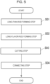
- the method for manufacturing the flavor stick 1 includes: a step of forming the flavor rod by bundling plural thin rods, in each of which a flavor source containing an aerosol-source material is wrapped with inner wrapping paper, and wrapping the thin rods together with outer wrapping paper; and a connecting step in which the flavor rod and a mouthpiece are arranged in series and wrapped together with tipping paper.
- the step of forming the flavor rod includes a long-thin-rod forming step in which plural long thin rods are formed in parallel with each other along a transport direction of a wrapping machine by wrapping the flavor source containing the aerosol-source material with long-sheet-shaped thin-rod wrapping paper continuously in a longitudinal direction; a long-flavor-rod forming step in which the long thin rods are joined and wrapped together with long outer wrapping paper to form a long flavor rod; and a cutting step in which the long flavor rod is cut to a predetermined length to form the flavor rod.
- This method will be described with reference to Figs. 5 to 9 .
- Fig. 5 illustrates the steps for manufacturing the flavor stick 1 according to the first embodiment.
- Fig. 6 illustrates sections of a wrapping machine used to manufacture the flavor rod 2 according to the first embodiment.
- Figs. 7 to 9 illustrate steps for manufacturing the flavor rod 2 according to the first embodiment.
- the flavor rod 2 including three thin rods 21 as illustrated in Fig. 3 is manufactured.
- the flavor rod 2 can be manufactured by using a known wrapping machine, such as the wrapping machine disclosed in Japanese Unexamined Patent Application Publication No. 7-184625 .
- long thin rods 21P 1 to 21P3 that are long and have a cylindrical cross-sectional shape are formed by wrapping the flavor source 24 with long-sheet-shaped thin-rod wrapping paper 23P in a tubular shape continuously in the longitudinal direction (long-thin-rod forming step).
- the long thin rods 21P1 to 21P3 are long, and are finally cut to a predetermined length to form each thin rod 21.
- Fig. 7 illustrates the long thin rods 21P1 to 21P3 formed in the thin-rod forming section 101.
- the thin-rod forming section 101 includes three parallel wrapping lines L1 to L3 that respectively wrap the long thin rods 21P1 to 21P3 in parallel with each other.
- the long thin rods 21P1 to 21P3 are wrapped in parallel with each other while moving along the lines in parallel with each other.
- each of the wrapping lines L1 to L3 has a flavor-source supply unit 101A and a shaping unit 101B positioned downstream of the flavor-source supply unit 101A.
- the flavor-source supply unit 101A of each of the wrapping lines L1 to L3 continuously supplies the flavor source 24 to the long inner wrapping paper 23P having a long strip shape transported along a transport path.
- the type of the flavor source 24 supplied from the flavor-source supply unit 101A to the long inner wrapping paper 23P may be the same or different between the wrapping lines L1 to L3.
- the shaping unit 101B of each of the wrapping lines L1 to L3 forms the long inner wrapping paper 23P into a tubular shape by gradually curling the long inner wrapping paper 23P inward after the flavor source 24 is applied thereto.
- the shaping unit 101B causes the long inner wrapping paper 23P and the flavor source 24 to pass through a guide member having a tubular guide inner wall surface, thereby forming the long inner wrapping paper 23P into a tubular shape while the flavor source 24 is wrapped therewith.
- This type of guide member is commonly known.
- a tongue disclosed in Japanese Unexamined Patent Application Publication No. 7-184625 may be used.
- the tubular guide inner wall surface of the guide member has a diameter that gradually decreases toward the downstream side along the transport path, and the long inner wrapping paper 23P passes through the guide member while being guided by the tubular guide inner wall surface.
- the long inner wrapping paper 23P is formed into a U-shape in cross-section, and then into a tubular shape.
- the flavor source 24 disposed inside the long inner wrapping paper 23P is appropriately compressed by the tubular guide inner wall surface.
- the long inner wrapping paper 23P is formed into a tubular shape, and end portions of the long inner wrapping paper 23P in the width direction are caused to overlap and bonded together.
- the long thin rods 21P1 to 21P3 having a long cylindrical shape are obtained.
- the long thin rods 21P1 to 21P3 transported along the transport path are joined and wrapped together with long outer wrapping paper 22P to form a long flavor rod 2P that is long and has a cylindrical cross-sectional shape (long-flavor-rod forming step).
- Fig. 8 illustrates the long thin rods 21P1 to 21P3 stacked on the long outer wrapping paper 22P having a long strip shape transported along the transport path in the thick-rod forming section 102.
- the long outer wrapping paper 22P is formed into a tubular shape while the long thin rods 21P1 to 21P3 are stacked on the long outer wrapping paper 22P as illustrated in Fig. 8 , and end portions of the long outer wrapping paper 22P in the width direction are caused to overlap and bonded together.
- the long flavor rod 2P that is long and has a cylindrical cross-sectional shape is obtained.
- the long flavor rod 2P is formed in a cylindrical cross-sectional shape in the thick-rod forming section 102
- a guide member similar to the above-described guide member used in the shaping unit 101B for example, the tongue disclosed in Japanese Unexamined Patent Application Publication No. 7-184625
- the long outer wrapping paper 22P is formed into a tubular shape by the guide member
- the long thin rods 21P1 to 21P3 positioned inside the long outer wrapping paper 22P are appropriately compressed by the tubular guide inner wall surface of the guide member.
- the cross-sectional shape of each of the long thin rods 21P1 to 21P3 can be changed from the initial circular shape (substantially perfectly circular shape) to an elliptical shape.
- the long thin rods 21P1 to 21P3 may have the same diameter or different diameters before the compression.
- the diameter of the long thin rods 21P1 to 21P3 before the compression may be set to about 3.5 mm to about 4 mm if, for example, the diameter of the flavor rod is 7 mm.
- glue (referred to as “rail glue” in the technical field) is used to bond the long inner wrapping paper 23P of each of the long thin rods 21P1 to 21P3 to the long outer wrapping paper 22P for bundling the long thin rods 21P1 to 21P3.
- the glue is applied to the inner surface of the long outer wrapping paper 22P along lines extending in the longitudinal direction of the long outer wrapping paper 22P.
- the long thin rods 21P1 to 21P3 are wrapped with the long outer wrapping paper 22P.
- the long thin rods 21P1 to 21P3 can be bonded to the long outer wrapping paper 22P.
- the positions at which the long thin rods 21P1 to 21P3 are bonded to the long outer wrapping paper 22P correspond to the above-described bonding portions BP.
- the long thin rods 21P1 to 21P3 are compressed from the outside and wrapped together with the long outer wrapping paper 22P to form the long flavor rod 2P.
- the long flavor rod 2P includes the long thin rods 21P1 to 21P3 having an elliptical cross-section inside the long outer wrapping paper 22P.
- the long thin rods 21P1 to 21P3 may be wrapped with the long outer wrapping paper 22P while being in tight contact with each other so that the central gap 25 is not formed in the central area of the long flavor rod 2P in cross-section or so that the cross-sectional area of the central gap 25 is reduced.
- the long flavor rod 2P that is long and transported in the transport direction is sequentially cut to a predetermined length, for example, to the length corresponding to a single flavor rod (cutting step).
- a predetermined length for example, to the length corresponding to a single flavor rod (cutting step).
- the flavor rod 2 having the predetermined length is obtained.
- the cross-sectional shape of the flavor rod 2 may be checked, and feedback control may be performed to adjust the positions of the thin rods 21 in cross-section and the amount of the flavor source 24, for example.
- the mouthpiece 3 is separately prepared, and the flavor rod 2 and the mouthpiece 3 are connected by being wrapped together with the tipping paper 8 (connecting step).
- the flavor stick 1 illustrated in Fig. 2 is obtained.
- Figs. 10 to 15 illustrate the second manufacturing method of the flavor stick 1.
- the second manufacturing method of the flavor stick 1 includes a step of forming the flavor rod and a connecting step.
- the step of forming the flavor rod includes a long-flavor-rod forming step and a cutting step.
- the step of forming the flavor rod of the second manufacturing method can be performed by using, for example, a known dual filter wrapping machine.
- Fig. 10 illustrates a front half of the long-flavor-rod forming step of the second manufacturing method. In Fig.
- reference sign 110 denotes a conveyor that transports various materials used to manufacture the flavor stick 1 in the direction shown by the empty arrow in Fig. 10 (transport direction).
- the long outer wrapping paper 22P is transported on the conveyor 110.
- Fig. 11 illustrates the shape of the conveyor 110 in cross-section orthogonal to the transport direction.
- the conveyor 110 has a concave groove 110A extending in the transport direction, and transports the long outer wrapping paper 22P and various other materials disposed in the groove 110A.
- the groove 110A of the conveyor 110 has suction holes for applying suction to the long outer wrapping paper 22P at the bottom thereof, and the long outer wrapping paper 22P is transported while being deformed along the wall surface of the groove 110A.
- Reference sign 111 denotes a leakage-suppressing-component supply drum that supplies double-length leakage-suppressing members 4W to the long outer wrapping paper 22P on the transport path.
- Each double-length leakage-suppressing member 4W is cut by a cutting knife into two halves at the center thereof in the length direction, and is thereby divided into two leakage-suppressing portions 4.
- each double-length leakage-suppressing member 4W is a member obtained by increasing the length of the leakage-suppressing portion 4 to twice the ordinary length (length of the leakage-suppressing portion 4 in a final shape included in the flavor stick 1).
- the leakage-suppressing portion 4 corresponds to a "first component” that constitutes a portion of the mouthpiece 3.
- the first component may be a structural member disposed at the front end of the mouthpiece 3.
- the double-length leakage-suppressing members 4W which are twice as long as the leakage-suppressing portion 4 (first component), correspond to "double-length first components".
- Reference signs 112 to 114 denote first to third thin-rod supply drums that supply double-length thin rods 21W1 to 21 W3 to the long outer wrapping paper 22P transported by the conveyor 110.
- Each of the double-length thin rods 21W1 to 21W3 is cut by a cutting knife into two halves at the center thereof in the length direction, and is thereby divided into two thin rods 21.
- the double-length thin rods 21W1 to 21W3 are members obtained by increasing the length of the thin rods 21 to twice the ordinary length (length of the thin rods 21 in a final shape included in the flavor stick 1).
- each of the double-length thin rods 21W1 to 21W3 is substantially identical to a thin rod formed by wrapping the flavor source 24 with the inner wrapping paper 23 that is twice as long as the ordinary length.
- the leakage-suppressing-component supply drum 111 and the first to third thin-rod supply drums 112 to 114 are arranged in that order (at a first position P1 to a fourth position P4) from the upstream side along the transport path of the conveyor 110.
- the leakage-suppressing-component supply drum 111 and the first to third thin-rod supply drums 112 to 114 are, for example, positioned above the conveyor 110, and have drum rotational axes orthogonal to the transport direction of the conveyor 110.
- the leakage-suppressing-component supply drum 111 and the first to third thin-rod supply drums 112 to 114 rotate while components to be supplied to the long outer wrapping paper 22P transported by the conveyor 110 are retained thereon by suction, and successively supply the components to be supplied to the long outer wrapping paper 22P at a predetermined timing.
- the supply drums 111 to 114 successively receive various materials from, for example, hoppers and intermediate drums (not illustrated).
- the leakage-suppressing-component supply drum 111 at the first position P1 supplies the double-length leakage-suppressing members 4W to the long outer wrapping paper 22P at regular intervals.
- the intervals between the double-length leakage-suppressing members 4W supplied to the long outer wrapping paper 22P are substantially equal to the length of the double-length thin rods 21W1 to 21 W3, and serve as rod-receiving spaces S1 in which the double-length thin rods 21W1 to 21W3 are to be placed.
- the first to third thin-rod supply drums 112 to 114 at the second to fourth positions P2 to P4 successively supply the double-length thin rods 21W1 to 21W3 to the rod-receiving spaces S1 between the double-length leakage-suppressing members 4W
- Fig. 12 illustrates the manner in which the leakage-suppressing-component supply drum 111 and the thin-rod supply drums 112 to 114 supply the respective components at the first to fourth positions P1 to P4.
- the double-length leakage-suppressing members 4W and the double-length thin rods 21W1 to 21W3 are successively supplied to the long outer wrapping paper 22P transported by the conveyor 110.
- the double thin rod 21W3 is supplied to each rod-receiving space S1 at the fourth position P4
- the three double thin rods 21W1 to 21W3 are bundled, and the bundles and the double-length leakage-suppressing members 4W are arranged in series on the long outer wrapping paper 22P (see, for example, Figs. 10 and 12 ).
- the term “bundle” means any arrangement in which the double-length thin rods 21 W1 to 21W3 are parallel and close to each other.
- Fig. 13 illustrates a second half of the long-flavor-rod forming step of the second manufacturing method.
- the double-length leakage-suppressing members 4W double-length first components
- the bundles denoted by reference sign 21W in Fig. 13 .
- the long flavor rod 2P' includes sections referred to as "thin-rod sections ST1" in which the bundles of the double-length thin rods 21W1 to 21W3 are disposed and sections referred to as "leakage-component sections ST2" in which the double-length leakage-suppressing members 4W are disposed.
- the known tongue (guide member) described in Japanese Unexamined Patent Application Publication No. 7-184625 may be used to wrap the bundles of the double-length thin rods 21W1 to 21W3 and the double-length leakage-suppressing members 4W with the long outer wrapping paper 22P.
- the double-length thin rods 21W1 to 21W3 can be compressed from the outside and wrapped with the long outer wrapping paper 22P.
- the long flavor rod 2P' is obtained.
- the long flavor rod 2P' is rod-shaped and includes the double-length thin rods 21W1 to 21W3 having an elliptical cross-sectional shape in the thin-rod sections ST1.
- FIG. 13 the conveyor 110 is omitted.
- reference sign 115 denotes a cutting knife of the wrapping machine.
- the cutting knife 115 cuts the long flavor rod 2P' at the center of each double-length leakage-suppressing member 4W in the length direction and at the center of each of the double-length thin rods 21W1 to 21W3 in the length direction.
- the long flavor rod 2P' is cut at the center of each thin-rod section ST1 and at the center of each leakage-component section ST2.
- each of the double-length thin rods 21W1 to 21W3 is divided into two thin rods 21 by being cut at the center thereof in the length direction.
- Each of the double-length leakage-suppressing members 4W is divided into two leakage-suppressing portions 4 by being cut at the center thereof in the length direction.
- the intermediate assembly MA see Fig. 14
- the leakage-suppressing portion 4 is connected to the rear end of the flavor rod 2 including the bundle of the thin rods 21, is formed.
- one cutting knife 115 is used to cut the long flavor rod 2P' in the cutting step.
- plural cutting knives 115 may be used to cut the long flavor rod 2P'.
- a first cutting knife and a second cutting knife may be disposed at different positions along the transport direction of the conveyor 110.
- the first cutting knife may be used to cut the thin-rod sections ST1
- the second cutting knife may be used to cut the leakage-component sections ST2.
- Either the first cutting knife or the second cutting knife may be disposed upstream of the other in the transport direction of the conveyor 110.
- Fig. 14 illustrates the intermediate assembly MA formed in the step of forming the flavor rod, and also illustrates the cooling portion 5, the filter portion 6, and the tipping paper 8 that are separately prepared.
- portions such as the leakage-suppressing portion 4, the cooling portion 5, and the filter portion 6 are simplified.
- the cooling portion 5 and the filter portion 6 correspond to "second components" that constitute a portion of the mouthpiece 3.
- the cooling portion 5 and the filter portion 6, which correspond to the second components can also be regarded as components of the mouthpiece 3 other than the leakage-suppressing portion 4, which corresponds to the first component.
- the second manufacturing method of the flavor stick 1 includes the connecting step.
- the intermediate assembly MA and one or more second components that constitute a portion of the mouthpiece 3 are wrapped together with the tipping paper 8 while the one or more second components are arranged in series with the leakage-suppressing portion 4 of the intermediate assembly MA that corresponds to the first component.
- the cooling portion 5 and the filter portion 6 correspond to the second components. Therefore, as illustrated in Fig. 14 , the cooling portion 5 and the filter portion 6 are arranged in series in that order from the rear end of the leakage-suppressing portion 4 of the intermediate assembly MA.
- the intermediate assembly MA, the cooling portion 5, and the filter portion 6 are connected together by being wrapped with the tipping paper 8.
- the flavor stick 1 is completed as illustrated in Fig. 15 .
- the internal structures of the leakage-suppressing portion 4, the cooling portion 5, and the filter portion 6 are not illustrated.
- the flavor inhalation device 30 illustrated in Fig. 1 is used for inhalation from the flavor stick 1 having the above-described structure.
- the flavor inhalation device 30 includes the heating chamber 31, the external heater 32, a power supply unit 33 that activates the external heater 32 by supplying electric power thereto, and a controller 34 that controls the electric power supplied to the external heater 32.
- the heating chamber 31 is a roughly cylindrical hollow portion defined by a chamber side peripheral wall 31B and a chamber bottom wall 31C, which constitute a portion of a housing of the flavor inhalation device 30.
- the external heater 32 is a heat-producing device, such as a metal-thin-film heater or a film heater, that produces heat from electric power supplied from the power supply unit 33.
- the metal thin film heater is a planar heater that is flexible and includes a metal thin film as a heat-producing body.
- the film heater is composed of, for example, a stack of layers including a layer made of an electrical insulating material and a layer made of a heating track, which is an example of a heating element.
- the type of the external heater 32 is not particularly limited as long as the flavor rod 2 inserted into the heating chamber 31 can be heated from the outer periphery.
- the external heater 32 may be provided to face the outer peripheral surface of the flavor rod 2 inserted into the heating chamber 31 from the front end to the rear end thereof.
- the flavor inhalation device 30 has an airflow path 36 that communicates with the chamber bottom wall 31C at one end thereof.
- the airflow path 35 communicates with an air inlet 37 formed in the housing of the flavor inhalation device 30 at the other end thereof.
- the flavor inhalation device 30 may start the heating operation in response to a starting operation performed on, for example, an operation switch disposed on the housing.
- the flavor inhalation device 30 may start the heating operation in response to a detection of the insertion of the flavor stick 1 (flavor rod 2) into the heating chamber 31.
- the controller 34 may include a sensor that detects the insertion of the flavor stick 1 (flavor rod 2) into the heating chamber 31, and start the heating operation in response to the detection of the insertion of the flavor stick 1 (flavor rod 2) by the sensor.
- the power supply unit 33 is a power supply that supplies electric power for heating to the external heater 32 through the controller 34.
- the controller 34 receives a request to start the heating operation in response to, for example, the operation on the operation switch or the detection of the insertion of the flavor stick 1 into the heating chamber 31, and causes the power supply unit 33 to supply the electric power to the external heater 32.
- the controller 34 may include a temperature sensor for detecting the temperature in the heating chamber 31 or the temperature of the flavor rod 2 and adjust the amount of current supplied from the power supply unit 33 to the external heater 32 based on the temperature detected by the temperature sensor.
- the flavor source 24 of each thin rod 21 is heated when the external heater 32 is activated while the flavor rod 2 is inserted in the heating chamber 31 of the flavor inhalation device 30.
- the aerosol-source material contained in the flavor source 24 is volatilized, and the flavor source 24 releases a flavor component, so that an aerosol containing the flavor component is generated.
- the aerosol containing the flavor component flows through each thin rod 21 toward the mouthpiece 3 (downstream), and enters the mouthpiece 3 from the rear end of each thin rod 21.
- the aerosol containing the flavor component successively flows through each of the aerosol flow paths 41A to 41C in the leakage-suppressing portion 4 at the front end of the mouthpiece 3, the cooling portion 5, and the filter portion 6, and is finally inhaled into the oral cavity of the user from the mouthpiece end 1a.
- the flavor rod 2 according to the present embodiment is formed by bundling the thin rods 21, in each of which the flavor source 24 is wrapped with the inner wrapping paper 23, together with the outer wrapping paper 22.
- the flavor source 24 in each of the thin rods 21 is individually wrapped with the inner wrapping paper 23. Accordingly, the flavor source 24 and the wrapping paper (inner wrapping paper 23) that wraps the flavor source 24 are in contact over a sufficiently large area in the flavor rod 2.
- the flavor source 24 in each thin rod 21 can be restrained from falling (spilling) from the front end 1b.
- each thin rod 21 has the inner wrapping paper 23 thereof bonded to the outer wrapping paper 22 at the corresponding bonding portion BP. Therefore, even when insertion resistance occurs due to friction between the chamber side peripheral wall 31B of the heating chamber 31 and the outer wrapping paper 22 upon insertion (attachment) of the flavor rod 2 into the heating chamber 31, the thin rods 21 disposed inside the outer wrapping paper 22 are not easily pushed and displaced toward the mouthpiece 3 (toward the rear end).
- each thin rod 21 of the flavor rod 2 has an elliptical cross-sectional shape with a minor axis extending in a radial direction of the flavor rod 2. Accordingly, each thin rod 21 can be easily disposed so that the major axis thereof extends along the circumferential direction of the flavor rod 2, and the area of the outer peripheral gaps 26 can be reduced.
- the flavor stick 1 includes the leakage-suppressing portion 4 disposed in a front end section of the mouthpiece 3.
- the leakage-suppressing portion 4 has the aerosol flow paths 41A to 41C extending in the axial direction to allow the aerosols generated in the thin rods 21 to flow therethrough, and includes the central blocking portion 42A and the outer peripheral blocking portions 42B that respectively face the central gap 25 and the outer peripheral gaps 26 in the flavor rod 2.
- the air introduced into the flavor rod 2 from the front end 1b can be restrained from leaking downstream through the central gap 25 and the outer peripheral gaps 26.
- the position, size, number, etc., of the aerosol flow paths in the leakage-suppressing portion 4 are not particularly limited as long as the aerosol from each thin rod 21 can flow downstream.
- the leakage-suppressing portion 4 may be omitted as long as air leakage through the central gap 25 and the outer peripheral gaps 26 is allowable.
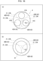
- Fig. 16 illustrates modifications of the leakage-suppressing portion 4 according to the first embodiment.
- Fig. 16 shows cross-sections of the modifications of the leakage-suppressing portion 4.
- the dashed lines show the outer shapes of the thin rods 21 in cross-section, that is, the positions of the outer surfaces 23A of the inner wrapping paper 23.
- the aerosol flow paths 41Ato 41C are disposed to face the rear ends of the respective thin rods 21.
- the cross-sectional area of the aerosol flow paths 41A to 41C is smaller than that of the thin rods 21.
- the rear end of each thin rod 21 extends along the blocking surface 42 (the central blocking portion 42A and the outer peripheral blocking portions 42B) of the leakage-suppressing portion 4 and the corresponding one of the aerosol flow paths 41A to 41C.
- each thin rod 21 partially faces the corresponding one of the aerosol flow paths 41A to 41C, and is partially supported from behind by being in contact with the blocking surface 42 (the central blocking portion 42A and the outer peripheral blocking portions 42B).
- the blocking surface 42 (the central blocking portion 42A and the outer peripheral blocking portions 42B) of the leakage-suppressing portion 4 serves as a stopper in regions in which the blocking surface 42 faces (is in contact with) the rear ends of the thin rods 21, the stopper restraining the thin rods 21 from being displaced when the flavor rod 2 is inserted into the heating chamber 31.
- the thin rods 21 disposed inside the outer wrapping paper 22 are not easily pushed and displaced toward the mouthpiece 3 (toward the rear end).
- the blocking surface 42 of the leakage-suppressing portion 4 partially supports the rear ends of the thin rods 21 to serve as a stopper (support portion) that restrains displacements of the thin rods 21, the inner wrapping paper 23 of each thin rod 21 does not need to be bonded to the outer wrapping paper 22.
- the leakage-suppressing portion 4 has a single aerosol flow path 41 extending along the rear ends of the thin rods 21 in a central region of the leakage-suppressing portion 4 in cross-section.
- the single aerosol flow path 41 partially faces the rear ends of the thin rods 21.
- the aerosol flow path 41 faces the rear end of the central gap 25 in the flavor rod 2.
- the structure illustrated in (b) may be employed as long as the air leakage through the central gap 25 is allowable.
- the flavor rod 2 may have a diameter set so that the flavor rod 2 is compressed by the chamber side peripheral wall 31B upon insertion into the heating chamber 31.
- the diameter of the heating chamber 31 in cross-section may be less than that of the flavor rod 2.
- the chamber side peripheral wall 31B compresses the flavor rod 2 from the outer periphery, thereby making the central gap 25 and the outer peripheral gaps 26 smaller or reducing the cross-sectional areas thereof.
- the leakage of air through the central gap 25 and the outer peripheral gaps 26 can be more easily restrained during inhalation from the flavor stick 1.
- the thin rods 21 included in the flavor rod 2 may include the flavor source 24 of the same type or different types.
- a first one of the thin rods 21 included in the flavor rod 2 may, for example, include the flavor source 24 that fills the space inside the inner wrapping paper 23 in the form of a uniformized sheet folded in a gathered form.
- a second one of the thin rods 21 may, for example, include the flavor source 24 that fills the space inside the inner wrapping paper 23 in the form of shredded tobacco.
- a third one of the thin rods 21 may, for example, include a plant material (for example, a herbal material) containing no tobacco component that fills the space inside the inner wrapping paper 23 as the flavor source 24.
- the above-described combination is, of course, an example.
- the flexibility in designing smoke flavor and taste can be increased, and rich smoke flavor and taste can be more easily produced.
- the thin rods 21 of the flavor rod 2 may contain the flavor source 24 of different types as described above, the thin rods 21 may have different cross-sectional areas. In such a case, the content of the flavor source 24 can be easily controlled based on the type of the flavor source 24.
- the aerosol containing the flavor component released from the flavor source 24 of each thin rod 21 is basically introduced into the mouthpiece 3 without being mixed with the other aerosols. Accordingly, when the thin rods 21 include the flavor source 24 of different types, the different types of flavor source 24 can release aerosols containing flavor components with more distinct flavors.
- the mouthpiece 3 may have a flow path structure that guides the aerosols from the thin rods 21 individually to the mouthpiece end 1a.
- the leakage-suppressing portion 4 is capable of causing aerosols from the thin rods 21 to individually flow through the aerosol flow paths 41A to 41C illustrated in Fig. 4 .
- the cooling portion 5 may, for example, include a sheet folded in a gathered form that defines flow paths extending in the axial direction of the mouthpiece 3 so that the aerosols from the thin rods 21 are not easily mixed.
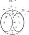
- FIG. 17 illustrates a cross-section of a flavor rod 2A according to the second embodiment.
- the flavor rod 2A includes two thin rods 21.
- the basic structure of the flavor rod 2A including two thin rods 21 is similar to that of the above-described flavor rod 2 including the three thin rods 21 (three-thin-rod type).
- the pair of thin rods 21 have substantially congruent elliptical shapes, and are arranged such that the major axes thereof are parallel to each other.
- the minor axis of each thin rod 21 extends in a radial direction of the flavor rod 2A. More specifically, the minor axes of the thin rods 21 are on the same straight line that passes through the central axis CL, and the pair of thin rods 21 are arranged such that the outer surfaces 23A of the inner wrapping paper 23 are in contact with each other in a central region of the flavor rod 2A in cross-section.
- the above-described central gap 25 can be eliminated, or the cross-sectional area of the central gap 25 can be reduced.
- the area of the outer peripheral gaps 26 in the flavor rod 2A can be reduced by arranging the pair of thin rods 21 such that the major axes thereof are in parallel with each other.
- the flavor rod 2A illustrated in Fig. 17 is also integrally connected to the mouthpiece 3 with the above-described tipping paper 8 to form the flavor stick 1 (see Fig. 2 ).
- the flavor rod 2A according to the present modification can basically be manufactured by steps similar to those for manufacturing the flavor rod 2 of the three-thin-rod type.
- the two-thin-rod type differs, of course, from the three-thin-rod type in that the number of thin rods 21 is two. Therefore, in the present embodiment, two long thin rods 21P1 and 21P2 are provided in the above-described long-thin-rod forming step. Assuming the diameter of the flavor rod 2 to be manufactured is 7 mm, the diameter of the two long thin rods 21P1 and 21P2 (before compression) may be set to about 4 mm to about 4.5 mm.
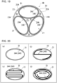
- Fig. 18 illustrates cross-sections of the leakage-suppressing portion 4 according to the second embodiment.
- the dashed lines show the outer shapes of the thin rods 21 in cross-section, that is, the positions of the outer surfaces 23A of the inner wrapping paper 23.
- the leakage-suppressing portion 4 has a pair of aerosol flow paths 41A and 41B that extend therethrough along the central axis CL2 to individually cause aerosols from the pair of thin rods 21 to flow therethrough.
- the aerosol flow paths 41A and 41B have cross-sections congruent with those of the thin rods 21, and are disposed to face the respective thin rods 21.
- the leakage-suppressing portion 4 is structured such that the outer peripheral blocking portions 42B of the blocking surface 42 block the rear ends of the outer peripheral gaps 26 in the flavor rod 2A.
- the cross-sectional area of the aerosol flow paths 41A and 41B that face the respective thin rods 21 is smaller than that of the thin rods 21.
- the rear end of each thin rod 21 extends along the blocking surface 42 (outer peripheral blocking portions 42B) of the leakage-suppressing portion 4 and the corresponding one of the aerosol flow paths 41A and 41B.
- the rear end of each thin rod 21 partially faces the corresponding one of the aerosol flow paths 41A and 41B, and is partially supported from behind by being in contact with the blocking surface 42 (outer peripheral blocking portions 42B).
- the blocking surface 42 (outer peripheral blocking portions 42B) of the leakage-suppressing portion 4 serves as a stopper (support member) in regions in which the blocking surface 42 faces (is in contact with) the rear ends of the thin rods 21, the stopper restraining the thin rods 21 from being displaced. Accordingly, even when insertion resistance occurs upon insertion of the flavor rod 2A into the heating chamber 31, the thin rods 21 can be restrained from being pushed toward the mouthpiece 3 (toward the rear end).
- the leakage-suppressing portion 4 includes a single aerosol flow path 41 in a central region of the leakage-suppressing portion 4 in cross-section, and the blocking surface 42 (outer peripheral blocking portions 42B) partially blocks the rear ends of the outer peripheral gaps 26 in the flavor rod 2A.
- flavor rods 2 and 2A the space inside the inner wrapping paper 23 of each thin rod 21 is filled with the flavor source 24.
- the flavor source is not necessarily provided in this form, and may be provided in various forms as long as the flavor source and the aerosol-source material are disposed in the space inside the inner wrapping paper 23.
- Fig. 19 illustrates a cross-section of a flavor rod 2B according to the third embodiment.
- the flavor rod 2B differs from the flavor rod 2 of the first embodiment only in the form of the flavor source containing an aerosol disposed inside the inner wrapping paper 23 of each thin rod 21, and other structures are similar to those of the flavor rod 2.
- reference sign 24A denotes a flavor source disposed inside the inner wrapping paper 23.
- the flavor source 24A contains the flavor source, the aerosol-source material, and a holding substrate 240 that holds the flavor source and the aerosol-source material.
- the flavor source may be, for example, the above-described flavoring agent.
- the holding substrate 240 of the flavor source 24A is a substrate sheet impregnated with a liquid flavoring agent and an aerosol-source material, and the material of the holding substrate may be, for example, a nonwoven fabric.
- the flavoring agent with which the holding substrate 240 (substrate sheet) of the flavor source 24A is impregnated may contain no tobacco component.
- the holding substrate 240 (substrate sheet) of the flavor source 24A may, for example, be bonded to the inner surface of the inner wrapping paper 23 of each thin rod 21.
- the thickness of the holding substrate 240 (substrate sheet) is not particularly limited, and may be, for example, about 0.1 mm to about 2 mm.
- plural long thin rods may be formed in parallel with each other along the transport direction of the wrapping machine by wrapping a long sheet-shaped substrate sheet impregnated with the flavor source and the aerosol-source material with long-sheet-shaped thin-rod wrapping paper into a tubular shape continuously in the longitudinal direction.
- the long-flavor-rod forming step and the cutting step performed subsequently are similar to those in the above-described first embodiment.
- the thin rods 21 may include the flavor source 24A containing the flavor source (flavoring agent) of the same type or different types.
- the holding substrate 240 (substrate sheet) of the flavor source 24A of each thin rod 21 has a tubular cross-sectional shape in the example illustrated in Fig. 19 , the cross-sectional shape is not limited to this.
- the holding substrate 240 (substrate sheet) may have any cross-sectional shape, such as a C-shape, an S-shape, or a spiral shape.
- a substrate sheet impregnated with a liquid flavoring agent and an aerosol-source material may be shredded into small pieces, and the space inside the inner wrapping paper 23 may be filled with these pieces.
- One or more of the thin rods 21 included in the flavor rod 2A may, of course, be replaced with the thin rods 21 including the flavor source 24 composed of the tobacco filler described with reference to Fig. 3 .
- Fig. 20 illustrates variants of the flavor source 24A of each thin rod 21 according to the third embodiment.
- Fig. 20 shows a flavor source 24A (holding substrate 240) having a C-shape;
- c) shows a flavor source 24A (holding substrate 240) having a meandering shape;
- d) shows a flavor source 24A (holding substrate 240) having a spiral shape.
- the variants illustrated in Fig. 14 are, of course, also examples of the flavor source 24A (holding substrate 240).
- the ratio of the total cross-sectional area of the central gap 25 and the outer peripheral gaps 26 to the cross-sectional area of the flavor rod 2 is not particularly limited, and may be, for example, 10% or less, preferably 5% or less. In this case, the downstream leakage of air through the central gap 25 and the outer peripheral gaps 26 can be reduced.
- the number of thin rods 21 included in the flavor rod 2 is not particularly limited as long as two or more thin rods 21 are provided. However, to restrain the flavor source 24 from falling from the front end of each thin rod 21 and facilitate manufacturing of the flavor rod 2, three or more thin rods 21 are preferably provided. The number of thin rods 21 may be changed along the axial direction of the flavor rod 2. For example, three thin rods 21 may be disposed adjacent to the front end of the flavor rod 2, and two thin rods 21 may be disposed adjacent to the rear end of the flavor rod 2.
- the inner wrapping paper 23 of each thin rod 21 is preferably made of a material with a high heat transfer performance to ensure efficient transmission of heat from the external heater 32 to the flavor source 24 disposed inside the inner wrapping paper 23. Therefore, the inner wrapping paper 23 is preferably made of a low-basis-weight, high-density material.
- the inner wrapping paper 23 preferably has a basis weight of 10 gsm or more and 40 gsm or less and a density of 1 g/cm 3 or more and 1.5 g/cm 3 or less.
- a coating agent, such as pectin or sodium alginate, may be applied to the inner wrapping paper 23 to improve the heat transfer performance.
- the inner wrapping paper 23 may be composed of a material having a high heat transfer performance, such as aluminum-laminated paper.
- the inner wrapping paper 23 is preferably made of a low-air-permeability material to suppress leakage of the aerosol through the central gap 25 and the outer peripheral gaps 26.
- the inner wrapping paper 23 may have an air permeability of 0 CORESTA unit (CU) or more and 200 CORESTA unit (CU) or less.
- the above-described air permeability may be measured in accordance with, for example, ISO 2965:2009.
- the outer wrapping paper 22 of the flavor rod 2 is preferably made of a material with a high heat transfer performance to ensure efficient transmission of heat from the external heater 32 to the thin rods 21 (flavor source 24) disposed inside the outer wrapping paper 22. Therefore, the outer wrapping paper 22 is preferably made of a low-basis-weight, high-density material.
- the outer wrapping paper 22 preferably has a basis weight of 10 gsm or more and 40 gsm or less and a density of 1 g/cm 3 or more and 1.5 g/cm 3 or less.
- a coating agent, such as pectin or sodium alginate, may be applied to the outer wrapping paper 22 to improve the heat transfer performance.
- the outer wrapping paper 22 may be composed of a material having a high heat transfer performance, such as aluminum-laminated paper.
- the coefficient of static friction between the external heater 32 and the outer wrapping paper 22 is preferably adjusted to 0.45 or more and 0.75 or less, and the coefficient of kinetic friction between the external heater 32 and the outer wrapping paper 22 is preferably adjusted to 0.4 or more and 0.7 or less.
- the tensile strength of the outer wrapping paper 22 is preferably 10 to 20 N/15 mm, and the wet tensile strength of the outer wrapping paper 22 is preferably 5 to 20 N/15 mm.
- the tensile strength of the outer wrapping paper 22 is measured in accordance with, for example, JIS P 8113.
- the wet tensile strength of the outer wrapping paper 22 may be measured based on, for example, a wet tensile strength test described in Japanese Unexamined Patent Application Publication No. 2019-187451 .
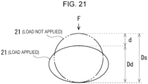
- Each thin rod 21 preferably has a hardness of 60% or more and 85% or less when the space inside the inner wrapping paper 23 is filled with the flavor source 24.
- the term "hardness” means the resistance to deformation of the thin rod 21 along cross-section.
- the hardness of the thin rod 21 can be measured based on, for example, the test method described in Japanese Unexamined Patent Application Publication (Translation of PCT Application) No. 2019-506868 (paragraphs 0029-0031, Fig. 1 ).
- the test for measuring the hardness of the thin rod 21 can be performed in accordance with the standard operation procedure for Borgwaldt Hardness Tester H10 (produced by Heinr Borgwaldt GmbH).
- Ds is the height of the thin rod 21 in the radial direction before a load is applied by the Borgwaldt Hardness Tester H10
- Dd is the height of the thin rod 21 in the radial direction after a constant load (88g) is applied to the thin rod 21 in the radial direction for a predetermined load time (5 seconds) by a load bar of Borgwaldt Hardness Tester H10.
- Fig. 21 is a schematic diagram illustrating the measurement of the hardness of the thin rod 21.
- reference sign F denotes the load applied to the thin rods 21 in the radial direction in the measurement test.
- the flavor stick, the non-combustion-heating-type flavor inhalation product, and the method for manufacturing the flavor stick according to the present invention are not limited to the above-described embodiment.
- Various modes disclosed in the above-described embodiment and modifications may be combined with any other modes disclosed in this specification.
Landscapes
- Cigarettes, Filters, And Manufacturing Of Filters (AREA)
- Manufacture Of Tobacco Products (AREA)
Abstract
Description
- The present invention relates to a flavor stick, a non-combustion-heating-type flavor inhalation product, and a method for manufacturing the flavor stick.
- Flavor sticks for use with a non-combustion-type flavor inhaler for inhaling flavor derived from a flavor source without combustion are known. An example of a known flavor stick includes a flavor rod and a mouthpiece disposed downstream of the flavor rod. The flavor rod is formed by filling a space inside wrapping paper with a filler including a flavor source, such as a tobacco material, and an aerosol-source material, such as glycerine or propylene glycol (see, for example, PTL 1).
- This type of flavor stick is used together with a flavor inhalation device for inhalation. Typically, the flavor rod of the flavor stick is inserted into a heating chamber of the flavor inhalation device, and a heater included in the flavor inhalation device heats the flavor source of the flavor rod without combustion. The non-combustion heating causes the flavor source to release an aerosol containing a flavor component, and a user inhales the aerosol through the mouthpiece disposed downstream of the flavor rod.
- An example of a known heating method used in the flavor inhalation device is an external heating method in which a heater (external heater) disposed on a peripheral wall surface that defines the heating chamber heats the flavor source of the flavor rod from the outer periphery.
-
- PTL 1: International Publication No.
2017-198838 - PTL 2:
Japanese Unexamined Patent Application Publication No. 7-184625 - PTL 3:
Japanese Patent No. 5220762 - The flavor rod included in the flavor stick according to the related art is formed simply by wrapping a single sheet of wrapping paper around the outer periphery of the flavor source. Therefore, the filler that fills the space inside the wrapping paper easily falls from the front end of the flavor rod.
- The present invention has been made in light of the above-described circumstances, and its object is to provide a technology that relates to a flavor stick for inhalation using a flavor inhalation device based on an external heating method, and with which a flavor source that fills the space inside wrapping paper does not easily fall from the front end of a flavor rod. Solution to Problem
- To achieve the above-described object, a flavor stick according to the present invention includes: a flavor rod configured to be inserted into a heating chamber of a flavor inhalation device and heated from an outer periphery by an external heater disposed in or on a side peripheral portion of the heating chamber; and a mouthpiece connected to a rear end of the flavor rod. The flavor rod includes a plurality of thin rods and outer wrapping paper with which the plurality of thin rods are bundled and wrapped. Each of the plurality of thin rods includes inner wrapping paper, a flavor source, and an aerosol-source material, the flavor source and the aerosol-source material being disposed inside the inner wrapping paper.
- The inner wrapping paper of each of the plurality of thin rods may be bonded to the outer wrapping paper.
- The mouthpiece may include a leakage-suppressing portion in a front end section thereof, the leakage-suppressing portion being connected to a rear end of the flavor rod and including an aerosol flow path and a blocking portion, the aerosol flow path extending in the axial direction and allowing an aerosol generated in the plurality of thin rods to flow therethrough, the blocking portion blocking a rear end of a gap formed between the outer wrapping paper and the plurality of thin rods.
- The gap may include an outer peripheral gap formed adjacent to an outer periphery of the flavor rod in cross-section, and the leakage-suppressing portion may include an outer peripheral blocking portion that faces the outer peripheral gap.
- The gap may include a central gap formed in a central region of the flavor rod in cross-section, and the leakage-suppressing portion may include a central blocking portion that faces the central gap.
- The aerosol flow path may face rear ends of the plurality of thin rods.
- A rear end of each of the plurality of thin rods may extend along the blocking portion and the aerosol flow path. The blocking portion may serve as a stopper in regions in which the blocking portion faces the rear ends of the thin rods, the stopper restraining the thin rods from being displaced when the flavor rod is inserted into the heating chamber.
- The present invention may be applied to a non-combustion-type flavor inhalation product. A non-combustion-type flavor inhalation product according to the present invention includes the above-described flavor stick and a flavor inhalation device used for inhalation from the flavor stick, the flavor inhalation device including a heating chamber that allows insertion of the flavor rod of the flavor stick and an external heater disposed in or on a side peripheral portion of the heating chamber.
- The present invention may also be applied to a method for manufacturing a flavor rod configured to be inserted into a heating chamber of a flavor inhalation device and heated from an outer periphery by an external heater disposed in or on a side peripheral portion of the heating chamber. The method for manufacturing a flavor rod according to the present invention includes: a long-thin-rod forming step in which a plurality of long thin rods are formed in parallel with each other along a transport direction of a wrapping machine by wrapping the flavor source with long-sheet-shaped thin-rod wrapping paper continuously in a longitudinal direction; a long-flavor-rod forming step in which the plurality of long thin rods are joined and wrapped together with long outer wrapping paper to form a long flavor rod; and a cutting step in which the long flavor rod is cut to a predetermined length to form the flavor rod.
- The solutions to the problem according to the present invention may be applied in any possible combinations. Advantageous Effects of Invention
- The present invention provides a technology that relates to a flavor stick for inhalation using a flavor inhalation device based on an external heating method, and with which a flavor source that fills the space inside wrapping paper does not easily fall from the front end of a flavor rod.
-
- [
Fig. 1] Fig. 1 is a schematic diagram illustrating a flavor inhalation device for non-combustion heating of a flavor stick according to a first embodiment. - [
Fig. 2] Fig. 2 is a schematic diagram illustrating the internal structure of the flavor stick according to the first embodiment. - [
Fig. 3] Fig. 3 illustrates the structure viewed in the direction of arrow A inFig. 2 . - [
Fig. 4] Fig. 4 is a perspective view of a leakage-suppressing portion according to the first embodiment. - [
Fig. 5] Fig. 5 illustrates the steps for manufacturing a flavor rod according to the first embodiment. - [
Fig. 6] Fig. 6 illustrates a wrapping machine used to manufacture the flavor rod according to the first embodiment. - [
Fig. 7] Fig. 7 illustrates a step for manufacturing the flavor rod according to the first embodiment. - [
Fig. 8] Fig. 8 illustrates another step for manufacturing the flavor rod according to the first embodiment. - [
Fig. 9] Fig. 9 illustrates another step for manufacturing the flavor rod according to the first embodiment. - [
Fig. 10] Fig. 10 illustrates a long-flavor-rod forming step of a second manufacturing method. - [
Fig. 11] Fig. 11 illustrates the shape of a conveyor in cross-section orthogonal to a transport direction. - [
Fig. 12] Fig. 12 illustrates the manner in which a leakage-suppressing-component supply drum and thin-rod supply drums supply respective components at first to fourth positions. - [
Fig. 13] Fig. 13 illustrates the long-flavor-rod forming step of the second manufacturing method. - [
Fig. 14] Fig. 14 illustrates an intermediate assembly formed in a step of forming the flavor rod, and also illustrates a cooling portion, a filter portion, and tipping paper that are separately prepared. - [
Fig. 15] Fig. 15 illustrates a flavor stick manufactured by the second manufacturing method. - [
Fig. 16] Fig. 16 illustrates modifications of the leakage-suppressing portion. - [
Fig. 17] Fig. 17 illustrates a cross-section of a flavor rod according to a second embodiment. - [
Fig. 18] Fig. 18 illustrates cross-sections of leakage-suppressing portions according to the second embodiment. - [
Fig. 19] Fig. 19 illustrates a cross-section of a flavor rod according to a third embodiment. - [
Fig. 20] Fig. 20 illustrates variants of the flavor source included in the thin rod according to the third embodiment. - [
Fig. 21] Fig. 21 is a schematic diagram illustrating the measurement of the hardness of a thin rod. - A flavor stick and a non-combustion-type flavor inhalation product according to an embodiment of the present invention will now be described with reference to the drawings. The dimensions, materials, shapes, relative arrangements, etc., of structural elements described in the embodiment are not intended to limit the technical scope of the present invention only thereto unless specified otherwise.
-
Fig. 1 is a schematic diagram illustrating aflavor inhalation device 30 for non-combustion heating of a flavor stick according to a first embodiment.Fig. 2 is a schematic diagram illustrating the internal structure of aflavor stick 1 according to the first embodiment. Theflavor inhalation device 30 is an inhalation device used for inhalation from theflavor stick 1. Theflavor stick 1 and theflavor inhalation device 30 constitute a non-combustion-type flavor inhalation product. - The
flavor inhalation device 30 includes aheating chamber 31 capable of receiving aflavor rod 2 of theflavor stick 1 and having aninsertion opening 31A through which theflavor rod 2 can be inserted and extracted. Theheating chamber 31 of theflavor inhalation device 30 includes a chamber sideperipheral wall 31B (side peripheral portion) in which an electricexternal heater 32 for heating theflavor rod 2 from the outer periphery thereof is disposed. - The
flavor stick 1 includes theflavor rod 2 and amouthpiece 3. Theflavor rod 2 is inserted into theheating chamber 31 of theflavor inhalation device 30 and heated by theexternal heater 32. Themouthpiece 3 is connected to a rear end of theflavor rod 2. In the present embodiment, for example, theflavor stick 1 has a cylindrical rod shape that extends in one direction. InFig. 1 , reference sign CL denotes a central axis of theflavor stick 1. Theflavor rod 2 and themouthpiece 3 are arranged coaxially, and therefore the central axis CL is also the central axis of theflavor rod 2 and themouthpiece 3. - The cylindrical-rod-shaped
flavor rod 2 and themouthpiece 3 are arranged coaxially, and are connected together by being coaxially wrapped with tippingpaper 8.Reference sign 1a denotes amouthpiece end 1a formed at the rear end of theflavor stick flavor stick 1. Theflavor stick 1 is inserted into theheating chamber 31 of theflavor inhalation device 30 from thefront end 1b. - The
flavor rod 2 includes pluralthin rods 21 andouter wrapping paper 22 with which thethin rods 21 are bundled and wrapped.Fig. 3 illustrates the structure viewed in the direction of arrow A inFig. 2 .Fig. 3 is a front view of the flavor stick 1 (flavor rod 2) viewed from the front-end-1b side. Each of thethin rods 21 that constitute theflavor rod 2 includesinner wrapping paper 23, and also includes a flavor source and an aerosol-source material disposed inside theinner wrapping paper 23. Although theflavor rod 2 includes threethin rods 21 in the example illustrated inFig. 3 , the number ofthin rods 21 is not particularly limited as long as two or morethin rods 21 are provided. Eachthin rod 21 has a central axis extending parallel to the central axis CL of theflavor stick 1, and extends over the entire length of theflavor rod 2. InFig. 3 ,reference sign 24 denotes the flavor source containing the aerosol-source material. Here, an example in which a tobacco filler is used as the flavor source will be described. - When the
flavor inhalation device 30 is used for inhalation from theflavor stick 1, theexternal heater 32 is activated while theflavor rod 2 of theflavor stick 1 is inserted in the heating chamber. As a result, the flavor source 24 (tobacco filler) containing the aerosol-source material is heated in eachthin rod 21, so that an aerosol containing a flavor component (for example, a tobacco component) is released. The aerosol containing the flavor component (for example, the tobacco component) generated in theflavor rod 2 is transmitted to themouthpiece end 1a through themouthpiece 3 and inhaled by a user. - The tobacco filler used as the
flavor source 24 may contain shredded tobacco. The material of the shredded tobacco contained in the tobacco filler is not particularly limited, and a known material, such as lamina and midrib, may be used. The material may be obtained by crushing dried tobacco leaves into crushed tobacco, uniformizing the crushed tobacco into a sheet (hereinafter also referred to simply as a "uniformized sheet"), and shredding the uniformized sheet. There are plural known methods for manufacturing the uniformized sheet, that is, for crushing tobacco leaves into pieces and forming the pieces into a uniformized sheet. The first method is to produce a sheet by using a papermaking process (sheet-making method). The second is a method of mixing a suitable solvent, such as water, and crushed tobacco leaves into a uniform mixture, casting the uniform mixture on a metal plate or a metal-plate belt, and performing a drying process to produce a cast sheet (slurry method). The third is a method of mixing a suitable solvent, such as water, and crushed tobacco leaves into a uniform mixture and forming the uniform mixture into a sheet shape by extrusion molding to produce a rolled sheet (rolling method). - Alternatively, the tobacco filler may be tobacco strands obtained by cutting the above-described uniformized sheet. The tobacco strands are about as long as the
thin rods 21 in the axial direction, and the space inside theinner wrapping paper 23 may be filled with the tobacco strands arranged such that the longitudinal directions thereof coincide with the axial direction of thethin rods 21. It is, of course, not necessary that all the tobacco strands included in eachthin rod 21 be arranged to extend in the axial direction of thethin rods 21, and some of the tobacco strands (for example, 50% or more of the total amount of tobacco strands) may be arranged to extend in the axial direction of thethin rods 21. Alternatively, the tobacco filler may be the above-described uniformized sheet folded in a gathered form. - Various types of tobacco may be used to form the tobacco filler. For example, flue-cured tobacco, burley tobacco, orient tobacco, domestic tobacco, other types of nicotiana tabacum or nicotiana rustica, or a mixture thereof may be used.
- The tobacco filler may contain a flavoring agent. The type of the flavoring agent contained in the tobacco filler is not particularly limited. The flavoring agent may be, for example, acetanisole, acetophenone, acetylpyrazine, 2-acetylthiazole, alfalfa extract, amyl alcohol, amyl butyrate, trans-anethole, star anise oil, apple juice, Peru balsam oil, beeswax absolute, benzaldehyde, benzoin resinoid, benzyl alcohol, benzyl benzoate, benzyl phenylacetate, benzyl propionate, 2,3-butanedione, 2-butanol, butyl butyrate, butyric acid, caramel, cardamom oil, carob absolute, β-carotene, carrot juice, L-carvone, β-caryophyllene, cassia bark oil, cedarwood oil, celery seed oil, chamomile oil, cinnamaldehyde, cinnamic acid, cinnamyl alcohol, cinnamyl cinnamate, citronella oil, DL-citronellol, clary sage extract, cocoa, coffee, cognac oil, coriander oil, cuminaldehyde, davana oil, δ-decalactone, γ-decalactone, decanoic acid, dill herb oil, 3,4-dimethyl-1,2-cyclopentanedione, 4,5-dimethyl-3-hydroxy-2,5-dihydrofuran-2-one, 3,7-dimethyl-6-octenoic acid, 2,3-dimethylpyrazine, 2,5-dimethylpyrazine, 2,6-dimethylpyrazine, ethyl 2-methylbutyrate, ethyl acetate, ethyl butyrate, ethyl hexanoate, ethyl isovalerate, ethyl lactate, ethyl laurate, ethyl levulinate, ethyl maltol, ethyl octanoate, ethyl oleate, ethyl palmitate, ethyl phenylacetate, ethyl propionate, ethyl stearate, ethyl valerate, ethyl vanillin, ethyl vanillin glucoside, 2-ethyl-3, (5 or 6)-dimethylpyrazine, 5-ethyl-3-hydroxy-4-methyl-2(5H)-furanone, 2-ethyl-3-methylpyrazine, eucalyptol, fenugreek absolute, genet absolute, gentian root infusion, geraniol, geranyl acetate, grape juice, guaiacol, guava extract, γ-heptalactone, γ-hexalactone, hexanoic acid, cis-3-hexen-1-ol, hexyl acetate, hexyl alcohol, hexyl phenylacetate, honey, 4-hydroxy-3-pentenoic acid lactone, 4-hydroxy-4-(3-hydroxy-1-butenyl)-3,5,5-trimethyl-2-cyclohexen-1-one, 4-(para-hydroxyphenyl)-2-butanone, sodium 4-hydroxyundecanoate, immortelle absolute, β-ionone, isoamyl acetate, isoamyl butyrate, isoamyl phenylacetate, isobutyl acetate, isobutyl phenylacetate, jasmine absolute, kola nut tincture, labdanum oil, terpeneless lemon oil, licorice extract, linalool, linalyl acetate, lovage root oil, maltol, maple syrup, menthol, menthone, L-menthyl acetate, para-methoxybenzaldehyde, methyl-2-pyrrolyl ketone, methyl anthranilate, methyl phenylacetate, methyl salicylate, 4'-methylacetophenone, methylcyclopentenolone, 3-methylvaleric acid, mimosa absolute, molasses, myristic acid, nerol, nerolidol, γ-nonalactone, nutmeg oil, δ-octalactone, octanal, octanoic acid, orange flower oil, orange oil, orris root oil, palmitic acid, ω-pentadecalactone, peppermint oil, petitgrain Paraguay oil, phenethyl alcohol, phenethyl phenylacetate, phenylacetic acid, piperonal, plum extract, propenyl guaethol, propyl acetate, 3-propylidene phthalide, prune juice, pyruvic acid, raisin extract, rose oil, rum, sage oil, sandalwood oil, spearmint oil, styrax absolute, marigold oil, tea distillate, α-terpineol, terpinyl acetate, 5,6,7,8-tetrahydroquinoxaline, 1,5,5,9-tetramethyl-13-oxacyclo(8.3.0.0(4.9))tridecane, 2,3,5,6-tetramethylpyrazine, thyme oil, tomato extract, 2-tridecanone, triethyl citrate, 4-(2,6,6-trimethyl-1-cyclohexenyl)2-buten-4-one, 2,6,6-trimethyl-2-cyclohexene-1,4-dione, 4-(2,6,6-trimethyl-1,3-cyclohexadienyl)2-buten-4-one, 2,3,5-trimethylpyrazine, γ-undecalactone, γ-valerolactone, vanilla extract, vanillin, veratraldehyde, violet leaf absolute, N-ethyl-p-menthane-3-carboxamide (WS-3), and ethyl-2-(p-menthane-3-carboxamide) acetate (WS-5). Menthol is particularly preferred. These flavors may be used alone or in combination of two or more. The size of the shredded tobacco contained in the tobacco filler and the water content of the
flavor source 24 are not particularly limited. - The
flavor source 24 included in eachthin rod 21 may contain no tobacco material. This type offlavor source 24 may be a plant material containing no tobacco component. In other words, eachthin rod 21 may contain one or more selected from mesophyll, vein, stem, root, flower, seed, and pulp of a plant containing no tobacco component. A herbal material is a plant material containing no tobacco component suitable for use as the flavor source. Examples of the herbal material include allspice, allspice, black pepper, northern bugweed, calamus root, catmint, catuaba, cayenne pepper, chaga, chervil, cinnamon, Chinese ginseng, St. John's wort, green tea, black tea, black cohosh, cayenne, chamomile, amsonia, cocoa, honeybush, echinacea, feverfew, ginger, goldenseal, lavender, licorice, sweet marjoram, milk thistle, mint (menthe), oolong tea, oregano, pennyroyal, peppermint, red clover, rooibos (red or green), rosehip, rosemary, sage, clary sage, savory, spearmint, gotu kola, thyme, turmeric, valerian, wintergreen, yellow dock, yerba mate, yerba santa, bacopa monniera, ashwagandha, capsicum, Chinese lantern plant, and marian thistle. - The flavor source included in each
thin rod 21 may, of course, contain a mixture of the tobacco material and the above-described herbal material. - The aerosol-source material is a substance that is volatilized when heated by the heater of the
flavor inhalation device 30 and releases a volatile substance that generates an aerosol when cooled. The aerosol-source material is, for example, liquid. The type of the aerosol-source material is not particularly limited, and extracts from various natural products and/or components thereof can be selected depending on the intended use. Examples of the aerosol-source material include glycerol, propylene glycol, triacetin, 1,3-butanediol, and mixtures thereof. - In the example illustrated in
Fig. 3 , eachthin rod 21 has an elliptical cross-sectional shape with a minor axis extending in a radial direction of theflavor rod 2. More specifically, the minor axis of eachthin rod 21 extends radially from the central axis CL of theflavor rod 2. InFig. 3 , reference sign BP denotes bonding portions at which theouter surfaces 23A of theinner wrapping paper 23 of thethin rods 21 are bonded to theinner surface 22A of theouter wrapping paper 22. Theouter surfaces 23A of theinner wrapping paper 23 are surfaces opposite to the surfaces (inner surfaces) facing theflavor source 24. Eachthin rod 21 may have a shape other than the elliptical shape. - The
mouthpiece 3 will now be described. Themouthpiece 3 includes a leakage-suppressingportion 4, a coolingportion 5, and afilter portion 6 arranged in that order from the front end. The leakage-suppressingportion 4, the coolingportion 5, and thefilter portion 6 of themouthpiece 3 are arranged coaxially, and wrapped together with wrappingpaper 7. Thewrapping paper 7 may be omitted, and theflavor rod 2, the leakage-suppressingportion 4, the coolingportion 5, and thefilter portion 6 may be wrapped together with the tippingpaper 8. -
Fig. 4 is a perspective view of the leakage-suppressingportion 4 according to the first embodiment. The leakage-suppressingportion 4 is positioned immediately behind theflavor rod 2, and is disposed in contact with the rear end of theflavor rod 2. Reference sign CL2 denotes a central axis of the leakage-suppressingportion 4. The leakage-suppressingportion 4 has a rod shape in which a plurality of through holes serving as aerosolflow paths 41Ato 41C are formed along the central axis CL2. The cross-sections of theaerosol flow paths 41A to 41C are, for example, congruent with the cross-sectional areas of the respectivethin rods 21 of theflavor rod 2, and theaerosol flow paths 41A to 41C are arranged such that the front ends thereof face the rear ends of the respectivethin rods 21. In other words, theaerosol flow paths 41A to 41C are connected to the respectivethin rods 21 along the central axis CL of theflavor stick 1. Thus, the aerosols generated in thethin rods 21 of theflavor rod 2 can individually flow into theaerosol flow paths 41A to 41C disposed downstream of thethin rods 21. - A gap may be formed along the central axis CL2 in a region between the
outer wrapping paper 22 of theflavor rod 2 and theinner wrapping paper 23 of eachthin rod 21. In the example illustrated inFig. 3 , acentral gap 25 is formed in a central region surrounded by the threethin rods 21 in cross-section of theflavor rod 2. InFig. 3 , thecentral gap 25 has a shape similar to a triangular shape in cross-section. However, the shape and size of thecentral gap 25 vary depending on the number, size, shape, arrangement, etc., of thethin rods 21 included in theflavor rod 2. Thethin rods 21 may be arranged such that nocentral gap 25 is formed. - In the example illustrated in
Fig. 3 , outerperipheral gaps 26 are formed adjacent to the outer periphery of theflavor rod 2 in cross-section. In a cross-section of theflavor rod 2, the outerperipheral gaps 26 are gaps formed in an outer peripheral region adjacent to and inside theouter wrapping paper 22. In the example illustrated inFig. 3 , the outerperipheral gaps 26 are gaps formed between thethin rods 21 that are adjacent to each other in the circumferential direction of theflavor rod 2, and are formed at intersecting positions between the major axes of thethin rods 21 that are adjacent to each other in the circumferential direction of theflavor rod 2. However, the shape and size of the outerperipheral gaps 26 vary depending on the number, size, shape, arrangement, etc., of thethin rods 21 included in theflavor rod 2. Thethin rods 21 may be arranged such that no outerperipheral gaps 26 are formed. - The above-described
central gap 25 and the outerperipheral gaps 26 extend along the central axis CL from thefront end 1b to the rear end of theflavor rod 2. - During inhalation from the
flavor stick 1, air is introduced into theflavor rod 2 from thefront end 1b and distributed between thethin rods 21. At this time, if the air introduced from thefront end 1b of theflavor rod 2 passes through thecentral gap 25 and the outerperipheral gaps 26, the air flows into themouthpiece 3 without passing through theflavor source 24 and serves as leakage air. Therefore, in the present embodiment, the leakage-suppressingportion 4 is disposed downstream of theflavor rod 2 to suppress or reduce the leakage of air through the outerperipheral gaps 26 in theflavor rod 2. - In
Fig. 4 ,reference sign 42 denotes a blocking surface (blocking portion) formed at the front end of the leakage-suppressingportion 4. The leakage-suppressingportion 4 has the blocking surface 42 (blocking portion) facing thecentral gap 25 and the outerperipheral gaps 26 in theflavor rod 2, thereby blocking the rear ends of thecentral gap 25 and the outerperipheral gaps 26. In the structure illustrated inFig. 4 , the blockingsurface 42 includes acentral blocking portion 42A and outer peripheral blockingportions 42B. Thecentral blocking portion 42A faces the above-describedcentral gap 25 to block the rear end of thecentral gap 25. The outer peripheral blockingportions 42B face the above-described outerperipheral gaps 26 to block the outerperipheral gaps 26. As a result, during inhalation from theflavor stick 1, the air introduced into theflavor rod 2 from thefront end 1b can be restrained from leaking downstream through thecentral gap 25 and the outerperipheral gaps 26. Accordingly, the air introduced from thefront end 1b during inhalation from theflavor stick 1 can be efficiently distributed to theflavor source 24 of eachthin rod 21 and contribute to the generation of the aerosol. The leakage-suppressingportion 4 also functions as a spacer that separates the coolingportion 5 from theflavor rod 2. - The leakage-suppressing
portion 4 may be formed of various materials. The leakage-suppressingportion 4 may be, for example, a hollow cellulose acetate tube. In other words, the leakage-suppressingportion 4 may be a cylindrical cellulose acetate fiber bundle having a center hole extending therethrough at the center thereof in cross-section. However, the material of the leakage-suppressingportion 4 is not particularly limited. It is not necessary that the material of the leakage-suppressingportion 4 have complete air impermeability as long as the ventilation resistance of the blockingsurface 42 of the leakage-suppressingportion 4 is higher than that of theflavor source 24 in eachthin rod 21 when theinternal heater 32 is inserted in theheater insertion hole 25. Since air passes through regions where the ventilation resistance is relatively low, the leakage-suppressingportion 4 having the above-described structure functions effectively. - The cooling
portion 5 is positioned immediately downstream of the leakage-suppressingportion 4 and is disposed in contact with the rear end of the leakage-suppressingportion 4. During inhalation from theflavor stick 1, the volatile substance released from the flavor rod 2 (flavor source 24) flows downstream through the coolingportion 5. The volatile substance released from the flavor rod 2 (flavor source 24) accelerates the generation of the aerosol when cooled in the coolingportion 5. In the structure illustrated inFig. 2 , the coolingportion 5 is composed of a hollow paper tube havingvent holes 5A that allow the introduction of outside air. It is not necessary that the coolingportion 5 have the vent holes 5A. The coolingportion 5 may be formed of a paper tube in which a cooling enhancement material, such as a polylactic acid sheet, is disposed to enhance the cooling of the volatile substance released from theflavor source 24. The coolingportion 5 may include a heat-absorbing agent disposed so as not to impede the flow of the volatile substance and the aerosol. For example, the coolingportion 5 may include a filter material having many flow paths (through holes) extending in the longitudinal direction (axial direction) of themouthpiece 3. - The
filter portion 6 is a segment positioned at the rear end of themouthpiece 3, that is, adjacent to themouthpiece end 1a. Thefilter portion 6 may be positioned immediately downstream of the coolingportion 5 and disposed in contact with the rear end of the coolingportion 5. In the structure illustrated inFig. 2 , thefilter portion 6 may include, for example, a filter material that captures predetermined components of the aerosol. The type of the filter material included in thefilter portion 6 is not particularly limited. For example, thefilter portion 6 may include a filter material formed of cellulose acetate fibers shaped in a cylindrical shape. Alternatively, thefilter portion 6 may be a center hole filter formed of cellulose acetate fibers shaped in a cylindrical shape and having a center hole extending along the axial direction. Thefilter portion 6 may also be a paper filter filled with cellulose fibers, or a paper tube including no filter element. Thefilter portion 6 may also be formed by selectively combining a solid filter material having a filter element, a center hole filter, a paper filter, and a paper tube including no filter element. - A method for manufacturing the
flavor stick 1 according to the present embodiment will now be described. The method for manufacturing theflavor stick 1 includes: a step of forming the flavor rod by bundling plural thin rods, in each of which a flavor source containing an aerosol-source material is wrapped with inner wrapping paper, and wrapping the thin rods together with outer wrapping paper; and a connecting step in which the flavor rod and a mouthpiece are arranged in series and wrapped together with tipping paper. Here, the step of forming the flavor rod includes a long-thin-rod forming step in which plural long thin rods are formed in parallel with each other along a transport direction of a wrapping machine by wrapping the flavor source containing the aerosol-source material with long-sheet-shaped thin-rod wrapping paper continuously in a longitudinal direction; a long-flavor-rod forming step in which the long thin rods are joined and wrapped together with long outer wrapping paper to form a long flavor rod; and a cutting step in which the long flavor rod is cut to a predetermined length to form the flavor rod. This method will be described with reference toFigs. 5 to 9 . -
Fig. 5 illustrates the steps for manufacturing theflavor stick 1 according to the first embodiment.Fig. 6 illustrates sections of a wrapping machine used to manufacture theflavor rod 2 according to the first embodiment.Figs. 7 to 9 illustrate steps for manufacturing theflavor rod 2 according to the first embodiment. In an example described below, theflavor rod 2 including threethin rods 21 as illustrated inFig. 3 is manufactured. Theflavor rod 2 can be manufactured by using a known wrapping machine, such as the wrapping machine disclosed inJapanese Unexamined Patent Application Publication No. 7-184625 - First, in a thin-
rod forming section 101 of the wrapping machine, longthin rods 21P 1 to 21P3 that are long and have a cylindrical cross-sectional shape are formed by wrapping theflavor source 24 with long-sheet-shaped thin-rod wrapping paper 23P in a tubular shape continuously in the longitudinal direction (long-thin-rod forming step). The long thin rods 21P1 to 21P3 are long, and are finally cut to a predetermined length to form eachthin rod 21. -
Fig. 7 illustrates the long thin rods 21P1 to 21P3 formed in the thin-rod forming section 101. The thin-rod forming section 101 includes three parallel wrapping lines L1 to L3 that respectively wrap the long thin rods 21P1 to 21P3 in parallel with each other. The long thin rods 21P1 to 21P3 are wrapped in parallel with each other while moving along the lines in parallel with each other. - In the thin-
rod forming section 101, each of the wrapping lines L1 to L3 has a flavor-source supply unit 101A and ashaping unit 101B positioned downstream of the flavor-source supply unit 101A. The flavor-source supply unit 101A of each of the wrapping lines L1 to L3 continuously supplies theflavor source 24 to the longinner wrapping paper 23P having a long strip shape transported along a transport path. The type of theflavor source 24 supplied from the flavor-source supply unit 101A to the longinner wrapping paper 23P may be the same or different between the wrapping lines L1 to L3. Theshaping unit 101B of each of the wrapping lines L1 to L3 forms the longinner wrapping paper 23P into a tubular shape by gradually curling the longinner wrapping paper 23P inward after theflavor source 24 is applied thereto. - The
shaping unit 101B causes the longinner wrapping paper 23P and theflavor source 24 to pass through a guide member having a tubular guide inner wall surface, thereby forming the longinner wrapping paper 23P into a tubular shape while theflavor source 24 is wrapped therewith. This type of guide member is commonly known. For example, a tongue disclosed inJapanese Unexamined Patent Application Publication No. 7-184625 inner wrapping paper 23P passes through the guide member while being guided by the tubular guide inner wall surface. As a result, the longinner wrapping paper 23P is formed into a U-shape in cross-section, and then into a tubular shape. When the longinner wrapping paper 23P is formed into a tubular shape, theflavor source 24 disposed inside the longinner wrapping paper 23P is appropriately compressed by the tubular guide inner wall surface. Thus, the longinner wrapping paper 23P is formed into a tubular shape, and end portions of the longinner wrapping paper 23P in the width direction are caused to overlap and bonded together. As a result, as illustrated inFig. 7 , the long thin rods 21P1 to 21P3 having a long cylindrical shape are obtained. - Next, in a thick-
rod forming section 102 of the wrapping machine, the long thin rods 21P1 to 21P3 transported along the transport path are joined and wrapped together with longouter wrapping paper 22P to form along flavor rod 2P that is long and has a cylindrical cross-sectional shape (long-flavor-rod forming step). -
Fig. 8 illustrates the long thin rods 21P1 to 21P3 stacked on the longouter wrapping paper 22P having a long strip shape transported along the transport path in the thick-rod forming section 102. In the thick-rod forming section 102, the longouter wrapping paper 22P is formed into a tubular shape while the long thin rods 21P1 to 21P3 are stacked on the longouter wrapping paper 22P as illustrated inFig. 8 , and end portions of the longouter wrapping paper 22P in the width direction are caused to overlap and bonded together. As a result, as illustrated inFig. 9 , thelong flavor rod 2P that is long and has a cylindrical cross-sectional shape is obtained. - Also when the
long flavor rod 2P is formed in a cylindrical cross-sectional shape in the thick-rod forming section 102, a guide member similar to the above-described guide member used in theshaping unit 101B (for example, the tongue disclosed inJapanese Unexamined Patent Application Publication No. 7-184625 outer wrapping paper 22P is formed into a tubular shape by the guide member, the long thin rods 21P1 to 21P3 positioned inside the longouter wrapping paper 22P are appropriately compressed by the tubular guide inner wall surface of the guide member. As a result, the cross-sectional shape of each of the long thin rods 21P1 to 21P3 can be changed from the initial circular shape (substantially perfectly circular shape) to an elliptical shape. The long thin rods 21P1 to 21P3 may have the same diameter or different diameters before the compression. When the long thin rods 21P1 to 21P3 have the same diameter, the diameter of the long thin rods 21P1 to 21P3 before the compression may be set to about 3.5 mm to about 4 mm if, for example, the diameter of the flavor rod is 7 mm. - In the long-flavor-rod forming step, glue (referred to as "rail glue" in the technical field) is used to bond the long
inner wrapping paper 23P of each of the long thin rods 21P1 to 21P3 to the longouter wrapping paper 22P for bundling the long thin rods 21P1 to 21P3. The glue is applied to the inner surface of the longouter wrapping paper 22P along lines extending in the longitudinal direction of the longouter wrapping paper 22P. Then, the long thin rods 21P1 to 21P3 are wrapped with the longouter wrapping paper 22P. Thus, the long thin rods 21P1 to 21P3 can be bonded to the longouter wrapping paper 22P. The positions at which the long thin rods 21P1 to 21P3 are bonded to the longouter wrapping paper 22P correspond to the above-described bonding portions BP. - As described above, the long thin rods 21P1 to 21P3 are compressed from the outside and wrapped together with the long
outer wrapping paper 22P to form thelong flavor rod 2P. Thelong flavor rod 2P includes the long thin rods 21P1 to 21P3 having an elliptical cross-section inside the longouter wrapping paper 22P. In the above-described long-flavor-rod forming step, the long thin rods 21P1 to 21P3 may be wrapped with the longouter wrapping paper 22P while being in tight contact with each other so that thecentral gap 25 is not formed in the central area of thelong flavor rod 2P in cross-section or so that the cross-sectional area of thecentral gap 25 is reduced. - Next, in a
cutting section 103 of the wrapping machine, thelong flavor rod 2P that is long and transported in the transport direction is sequentially cut to a predetermined length, for example, to the length corresponding to a single flavor rod (cutting step). As a result, theflavor rod 2 having the predetermined length is obtained. After thelong flavor rod 2P is cut to the predetermined length, the cross-sectional shape of theflavor rod 2 may be checked, and feedback control may be performed to adjust the positions of thethin rods 21 in cross-section and the amount of theflavor source 24, for example. - To form the
flavor stick 1, themouthpiece 3 is separately prepared, and theflavor rod 2 and themouthpiece 3 are connected by being wrapped together with the tipping paper 8 (connecting step). Thus, theflavor stick 1 illustrated inFig. 2 is obtained. - The manufacturing method described above with reference to
Figs. 5 to 9 is hereinafter referred to as a "first manufacturing method". A manufacturing method (second manufacturing method) that differs from the first manufacturing method will now be described.Figs. 10 to 15 illustrate the second manufacturing method of theflavor stick 1. The second manufacturing method of theflavor stick 1 includes a step of forming the flavor rod and a connecting step. The step of forming the flavor rod includes a long-flavor-rod forming step and a cutting step. The step of forming the flavor rod of the second manufacturing method can be performed by using, for example, a known dual filter wrapping machine.Fig. 10 illustrates a front half of the long-flavor-rod forming step of the second manufacturing method. InFig. 10 ,reference sign 110 denotes a conveyor that transports various materials used to manufacture theflavor stick 1 in the direction shown by the empty arrow inFig. 10 (transport direction). As illustrated inFig. 10 , the longouter wrapping paper 22P is transported on theconveyor 110.Fig. 11 illustrates the shape of theconveyor 110 in cross-section orthogonal to the transport direction. Theconveyor 110 has aconcave groove 110A extending in the transport direction, and transports the longouter wrapping paper 22P and various other materials disposed in thegroove 110A. For example, thegroove 110A of theconveyor 110 has suction holes for applying suction to the longouter wrapping paper 22P at the bottom thereof, and the longouter wrapping paper 22P is transported while being deformed along the wall surface of thegroove 110A. - In the second manufacturing method, various components used to form an intermediate assembly MA of the
flavor stick 1 are supplied to the longouter wrapping paper 22P transported by theconveyor 110 of the wrapping machine.Reference sign 111 denotes a leakage-suppressing-component supply drum that supplies double-length leakage-suppressingmembers 4W to the longouter wrapping paper 22P on the transport path. Each double-length leakage-suppressingmember 4W is cut by a cutting knife into two halves at the center thereof in the length direction, and is thereby divided into two leakage-suppressingportions 4. In other words, each double-length leakage-suppressingmember 4W is a member obtained by increasing the length of the leakage-suppressingportion 4 to twice the ordinary length (length of the leakage-suppressingportion 4 in a final shape included in the flavor stick 1). The leakage-suppressingportion 4 corresponds to a "first component" that constitutes a portion of themouthpiece 3. The first component may be a structural member disposed at the front end of themouthpiece 3. The double-length leakage-suppressingmembers 4W, which are twice as long as the leakage-suppressing portion 4 (first component), correspond to "double-length first components". - Reference signs 112 to 114 denote first to third thin-rod supply drums that supply double-length thin rods 21W1 to 21 W3 to the long
outer wrapping paper 22P transported by theconveyor 110. Each of the double-length thin rods 21W1 to 21W3 is cut by a cutting knife into two halves at the center thereof in the length direction, and is thereby divided into twothin rods 21. In other words, the double-length thin rods 21W1 to 21W3 are members obtained by increasing the length of thethin rods 21 to twice the ordinary length (length of thethin rods 21 in a final shape included in the flavor stick 1). In other words, each of the double-length thin rods 21W1 to 21W3 is substantially identical to a thin rod formed by wrapping theflavor source 24 with theinner wrapping paper 23 that is twice as long as the ordinary length. - As illustrated in
Fig. 10 , the leakage-suppressing-component supply drum 111 and the first to third thin-rod supply drums 112 to 114 are arranged in that order (at a first position P1 to a fourth position P4) from the upstream side along the transport path of theconveyor 110. The leakage-suppressing-component supply drum 111 and the first to third thin-rod supply drums 112 to 114 are, for example, positioned above theconveyor 110, and have drum rotational axes orthogonal to the transport direction of theconveyor 110. The leakage-suppressing-component supply drum 111 and the first to third thin-rod supply drums 112 to 114 rotate while components to be supplied to the longouter wrapping paper 22P transported by theconveyor 110 are retained thereon by suction, and successively supply the components to be supplied to the longouter wrapping paper 22P at a predetermined timing. The supply drums 111 to 114 successively receive various materials from, for example, hoppers and intermediate drums (not illustrated). - As illustrated in
Fig. 10 , the leakage-suppressing-component supply drum 111 at the first position P1 supplies the double-length leakage-suppressingmembers 4W to the longouter wrapping paper 22P at regular intervals. The intervals between the double-length leakage-suppressingmembers 4W supplied to the longouter wrapping paper 22P are substantially equal to the length of the double-length thin rods 21W1 to 21 W3, and serve as rod-receiving spaces S1 in which the double-length thin rods 21W1 to 21W3 are to be placed. The first to third thin-rod supply drums 112 to 114 at the second to fourth positions P2 to P4 successively supply the double-length thin rods 21W1 to 21W3 to the rod-receiving spaces S1 between the double-length leakage-suppressingmembers 4W -
Fig. 12 illustrates the manner in which the leakage-suppressing-component supply drum 111 and the thin-rod supply drums 112 to 114 supply the respective components at the first to fourth positions P1 to P4. As described above, the double-length leakage-suppressingmembers 4W and the double-length thin rods 21W1 to 21W3 are successively supplied to the longouter wrapping paper 22P transported by theconveyor 110. When the double thin rod 21W3 is supplied to each rod-receiving space S1 at the fourth position P4, the three double thin rods 21W1 to 21W3 are bundled, and the bundles and the double-length leakage-suppressingmembers 4W are arranged in series on the longouter wrapping paper 22P (see, for example,Figs. 10 and12 ). Here, the term "bundle" means any arrangement in which the double-lengththin rods 21 W1 to 21W3 are parallel and close to each other. -
Fig. 13 illustrates a second half of the long-flavor-rod forming step of the second manufacturing method. In the second half of the long-flavor-rod forming step, the double-length leakage-suppressingmembers 4W (double-length first components) and the bundles (denoted byreference sign 21W inFig. 13 ) of the double-length thin rods 21W1 to 21 W3 (double-length thin rods) arranged in series with the double-length leakage-suppressingmembers 4W are wrapped together with the longouter wrapping paper 22P. As a result, the bundles of the double-length thin rods 21W1 to 21W3 and the double-length leakage-suppressingmembers 4W are alternately arranged in the longitudinal direction and wrapped together with the longouter wrapping paper 22P to form along flavor rod 2P' having a long rod shape. Thelong flavor rod 2P' includes sections referred to as "thin-rod sections ST1" in which the bundles of the double-length thin rods 21W1 to 21W3 are disposed and sections referred to as "leakage-component sections ST2" in which the double-length leakage-suppressingmembers 4W are disposed. - Similarly to the long-flavor-rod forming step of the first manufacturing method, the known tongue (guide member) described in
Japanese Unexamined Patent Application Publication No. 7-184625 members 4W with the longouter wrapping paper 22P. Thus, the double-length thin rods 21W1 to 21W3 can be compressed from the outside and wrapped with the longouter wrapping paper 22P. As a result, thelong flavor rod 2P' is obtained. Thelong flavor rod 2P' is rod-shaped and includes the double-length thin rods 21W1 to 21W3 having an elliptical cross-sectional shape in the thin-rod sections ST1. - The cutting step of the second manufacturing method will now be described. In
Fig. 13 , theconveyor 110 is omitted. InFig. 13 ,reference sign 115 denotes a cutting knife of the wrapping machine. The cuttingknife 115 cuts thelong flavor rod 2P' at the center of each double-length leakage-suppressingmember 4W in the length direction and at the center of each of the double-length thin rods 21W1 to 21W3 in the length direction. In other words, in the cutting step, thelong flavor rod 2P' is cut at the center of each thin-rod section ST1 and at the center of each leakage-component section ST2. As described above, each of the double-length thin rods 21W1 to 21W3 is divided into twothin rods 21 by being cut at the center thereof in the length direction. Each of the double-length leakage-suppressingmembers 4W is divided into two leakage-suppressingportions 4 by being cut at the center thereof in the length direction. As a result of the above-described cutting step, the intermediate assembly MA (seeFig. 14 ), in which the leakage-suppressingportion 4 is connected to the rear end of theflavor rod 2 including the bundle of thethin rods 21, is formed. In the above-described example, onecutting knife 115 is used to cut thelong flavor rod 2P' in the cutting step. However, plural cuttingknives 115 may be used to cut thelong flavor rod 2P'. For example, a first cutting knife and a second cutting knife may be disposed at different positions along the transport direction of theconveyor 110. The first cutting knife may be used to cut the thin-rod sections ST1, and the second cutting knife may be used to cut the leakage-component sections ST2. Either the first cutting knife or the second cutting knife may be disposed upstream of the other in the transport direction of theconveyor 110. -
Fig. 14 illustrates the intermediate assembly MA formed in the step of forming the flavor rod, and also illustrates the coolingportion 5, thefilter portion 6, and thetipping paper 8 that are separately prepared. InFig. 14 , portions such as the leakage-suppressingportion 4, the coolingportion 5, and thefilter portion 6 are simplified. The coolingportion 5 and thefilter portion 6 correspond to "second components" that constitute a portion of themouthpiece 3. The coolingportion 5 and thefilter portion 6, which correspond to the second components, can also be regarded as components of themouthpiece 3 other than the leakage-suppressingportion 4, which corresponds to the first component. The second manufacturing method of theflavor stick 1 includes the connecting step. In the connecting step of the second manufacturing method, the intermediate assembly MA and one or more second components that constitute a portion of themouthpiece 3 are wrapped together with the tippingpaper 8 while the one or more second components are arranged in series with the leakage-suppressingportion 4 of the intermediate assembly MA that corresponds to the first component. In this example, the coolingportion 5 and thefilter portion 6 correspond to the second components. Therefore, as illustrated inFig. 14 , the coolingportion 5 and thefilter portion 6 are arranged in series in that order from the rear end of the leakage-suppressingportion 4 of the intermediate assembly MA. In this state, the intermediate assembly MA, the coolingportion 5, and thefilter portion 6 are connected together by being wrapped with the tippingpaper 8. As a result, theflavor stick 1 is completed as illustrated inFig. 15 . InFig. 15 , the internal structures of the leakage-suppressingportion 4, the coolingportion 5, and thefilter portion 6 are not illustrated. - The
flavor inhalation device 30 illustrated inFig. 1 is used for inhalation from theflavor stick 1 having the above-described structure. As illustrated inFig. 1 , theflavor inhalation device 30 includes theheating chamber 31, theexternal heater 32, apower supply unit 33 that activates theexternal heater 32 by supplying electric power thereto, and acontroller 34 that controls the electric power supplied to theexternal heater 32. Theheating chamber 31 is a roughly cylindrical hollow portion defined by a chamber sideperipheral wall 31B and a chamberbottom wall 31C, which constitute a portion of a housing of theflavor inhalation device 30. When theflavor stick 1 is inserted into theheating chamber 31, theflavor rod 2 is inserted through theinsertion opening 31A from thefront end 1b. - The
external heater 32 is a heat-producing device, such as a metal-thin-film heater or a film heater, that produces heat from electric power supplied from thepower supply unit 33. The metal thin film heater is a planar heater that is flexible and includes a metal thin film as a heat-producing body. The film heater is composed of, for example, a stack of layers including a layer made of an electrical insulating material and a layer made of a heating track, which is an example of a heating element. However, the type of theexternal heater 32 is not particularly limited as long as theflavor rod 2 inserted into theheating chamber 31 can be heated from the outer periphery. For example, theexternal heater 32 may be provided to face the outer peripheral surface of theflavor rod 2 inserted into theheating chamber 31 from the front end to the rear end thereof. - The
flavor inhalation device 30 has anairflow path 36 that communicates with thechamber bottom wall 31C at one end thereof. The airflow path 35 communicates with anair inlet 37 formed in the housing of theflavor inhalation device 30 at the other end thereof. - The
flavor inhalation device 30 may start the heating operation in response to a starting operation performed on, for example, an operation switch disposed on the housing. Alternatively, theflavor inhalation device 30 may start the heating operation in response to a detection of the insertion of the flavor stick 1 (flavor rod 2) into theheating chamber 31. For example, thecontroller 34 may include a sensor that detects the insertion of the flavor stick 1 (flavor rod 2) into theheating chamber 31, and start the heating operation in response to the detection of the insertion of the flavor stick 1 (flavor rod 2) by the sensor. - The
power supply unit 33 is a power supply that supplies electric power for heating to theexternal heater 32 through thecontroller 34. Thecontroller 34 receives a request to start the heating operation in response to, for example, the operation on the operation switch or the detection of the insertion of theflavor stick 1 into theheating chamber 31, and causes thepower supply unit 33 to supply the electric power to theexternal heater 32. - The
controller 34 may include a temperature sensor for detecting the temperature in theheating chamber 31 or the temperature of theflavor rod 2 and adjust the amount of current supplied from thepower supply unit 33 to theexternal heater 32 based on the temperature detected by the temperature sensor. - In the
flavor stick 1 having the above-described structure, theflavor source 24 of eachthin rod 21 is heated when theexternal heater 32 is activated while theflavor rod 2 is inserted in theheating chamber 31 of theflavor inhalation device 30. As a result, the aerosol-source material contained in theflavor source 24 is volatilized, and theflavor source 24 releases a flavor component, so that an aerosol containing the flavor component is generated. The aerosol containing the flavor component flows through eachthin rod 21 toward the mouthpiece 3 (downstream), and enters themouthpiece 3 from the rear end of eachthin rod 21. The aerosol containing the flavor component successively flows through each of theaerosol flow paths 41A to 41C in the leakage-suppressingportion 4 at the front end of themouthpiece 3, the coolingportion 5, and thefilter portion 6, and is finally inhaled into the oral cavity of the user from themouthpiece end 1a. - The
flavor rod 2 according to the present embodiment is formed by bundling thethin rods 21, in each of which theflavor source 24 is wrapped with theinner wrapping paper 23, together with theouter wrapping paper 22. In other words, in theflavor rod 2 according to the present embodiment, theflavor source 24 in each of thethin rods 21 is individually wrapped with theinner wrapping paper 23. Accordingly, theflavor source 24 and the wrapping paper (inner wrapping paper 23) that wraps theflavor source 24 are in contact over a sufficiently large area in theflavor rod 2. Thus, theflavor source 24 in eachthin rod 21 can be restrained from falling (spilling) from thefront end 1b. - In addition, in the
flavor rod 2 of the present embodiment, eachthin rod 21 has theinner wrapping paper 23 thereof bonded to theouter wrapping paper 22 at the corresponding bonding portion BP. Therefore, even when insertion resistance occurs due to friction between the chamber sideperipheral wall 31B of theheating chamber 31 and theouter wrapping paper 22 upon insertion (attachment) of theflavor rod 2 into theheating chamber 31, thethin rods 21 disposed inside theouter wrapping paper 22 are not easily pushed and displaced toward the mouthpiece 3 (toward the rear end). In addition, eachthin rod 21 of theflavor rod 2 has an elliptical cross-sectional shape with a minor axis extending in a radial direction of theflavor rod 2. Accordingly, eachthin rod 21 can be easily disposed so that the major axis thereof extends along the circumferential direction of theflavor rod 2, and the area of the outerperipheral gaps 26 can be reduced. - The
flavor stick 1 includes the leakage-suppressingportion 4 disposed in a front end section of themouthpiece 3. The leakage-suppressingportion 4 has theaerosol flow paths 41A to 41C extending in the axial direction to allow the aerosols generated in thethin rods 21 to flow therethrough, and includes thecentral blocking portion 42A and the outer peripheral blockingportions 42B that respectively face thecentral gap 25 and the outerperipheral gaps 26 in theflavor rod 2. Thus, during inhalation from theflavor stick 1, the air introduced into theflavor rod 2 from thefront end 1b can be restrained from leaking downstream through thecentral gap 25 and the outerperipheral gaps 26. The position, size, number, etc., of the aerosol flow paths in the leakage-suppressingportion 4 are not particularly limited as long as the aerosol from eachthin rod 21 can flow downstream. The leakage-suppressingportion 4 may be omitted as long as air leakage through thecentral gap 25 and the outerperipheral gaps 26 is allowable. -
Fig. 16 illustrates modifications of the leakage-suppressingportion 4 according to the first embodiment.Fig. 16 shows cross-sections of the modifications of the leakage-suppressingportion 4. InFig. 16 , the dashed lines show the outer shapes of thethin rods 21 in cross-section, that is, the positions of theouter surfaces 23A of theinner wrapping paper 23. In the modification illustrated in (a), the aerosolflow paths 41Ato 41C are disposed to face the rear ends of the respectivethin rods 21. As illustrated in (a), the cross-sectional area of theaerosol flow paths 41A to 41C is smaller than that of thethin rods 21. The rear end of eachthin rod 21 extends along the blocking surface 42 (thecentral blocking portion 42A and the outer peripheral blockingportions 42B) of the leakage-suppressingportion 4 and the corresponding one of theaerosol flow paths 41A to 41C. - In the above-described structure, the rear end of each
thin rod 21 partially faces the corresponding one of theaerosol flow paths 41A to 41C, and is partially supported from behind by being in contact with the blocking surface 42 (thecentral blocking portion 42A and the outer peripheral blockingportions 42B). As a result, the blocking surface 42 (thecentral blocking portion 42A and the outer peripheral blockingportions 42B) of the leakage-suppressingportion 4 serves as a stopper in regions in which the blockingsurface 42 faces (is in contact with) the rear ends of thethin rods 21, the stopper restraining thethin rods 21 from being displaced when theflavor rod 2 is inserted into theheating chamber 31. Accordingly, even when insertion resistance occurs due to friction between the chamber sideperipheral wall 31B of theheating chamber 31 and theouter wrapping paper 22 upon insertion (attachment) of theflavor rod 2 into theheating chamber 31, thethin rods 21 disposed inside theouter wrapping paper 22 are not easily pushed and displaced toward the mouthpiece 3 (toward the rear end). When the blockingsurface 42 of the leakage-suppressingportion 4 partially supports the rear ends of thethin rods 21 to serve as a stopper (support portion) that restrains displacements of thethin rods 21, theinner wrapping paper 23 of eachthin rod 21 does not need to be bonded to theouter wrapping paper 22. - In the modification illustrated in (b), the leakage-suppressing
portion 4 has a singleaerosol flow path 41 extending along the rear ends of thethin rods 21 in a central region of the leakage-suppressingportion 4 in cross-section. In other words, the singleaerosol flow path 41 partially faces the rear ends of thethin rods 21. In the example illustrated in (b), theaerosol flow path 41 faces the rear end of thecentral gap 25 in theflavor rod 2. However, the structure illustrated in (b) may be employed as long as the air leakage through thecentral gap 25 is allowable. - The
flavor rod 2 according to the present embodiment may have a diameter set so that theflavor rod 2 is compressed by the chamber sideperipheral wall 31B upon insertion into theheating chamber 31. For example, the diameter of theheating chamber 31 in cross-section (cross-section orthogonal to the direction of insertion and extraction of the flavor rod 2) may be less than that of theflavor rod 2. In this case, when theflavor rod 2 is inserted into theheating chamber 31, the chamber sideperipheral wall 31B compresses theflavor rod 2 from the outer periphery, thereby making thecentral gap 25 and the outerperipheral gaps 26 smaller or reducing the cross-sectional areas thereof. Thus, the leakage of air through thecentral gap 25 and the outerperipheral gaps 26 can be more easily restrained during inhalation from theflavor stick 1. - The
thin rods 21 included in theflavor rod 2 may include theflavor source 24 of the same type or different types. When thethin rods 21 include theflavor source 24 of different types, a first one of thethin rods 21 included in theflavor rod 2 may, for example, include theflavor source 24 that fills the space inside theinner wrapping paper 23 in the form of a uniformized sheet folded in a gathered form. A second one of thethin rods 21 may, for example, include theflavor source 24 that fills the space inside theinner wrapping paper 23 in the form of shredded tobacco. A third one of thethin rods 21 may, for example, include a plant material (for example, a herbal material) containing no tobacco component that fills the space inside theinner wrapping paper 23 as theflavor source 24. The above-described combination is, of course, an example. When at least one of thethin rods 21 included in theflavor rod 2 includes theflavor source 24 of the type different from that in the otherthin rods 21, the flexibility in designing smoke flavor and taste can be increased, and rich smoke flavor and taste can be more easily produced. - When the
thin rods 21 of theflavor rod 2 contain theflavor source 24 of different types as described above, thethin rods 21 may have different cross-sectional areas. In such a case, the content of theflavor source 24 can be easily controlled based on the type of theflavor source 24. - The outer periphery of the
flavor source 24 of each of thethin rods 21 included in theflavor rod 2 is covered by theinner wrapping paper 23. Therefore, the aerosol containing the flavor component released from theflavor source 24 of eachthin rod 21 is basically introduced into themouthpiece 3 without being mixed with the other aerosols. Accordingly, when thethin rods 21 include theflavor source 24 of different types, the different types offlavor source 24 can release aerosols containing flavor components with more distinct flavors. In this regard, themouthpiece 3 may have a flow path structure that guides the aerosols from thethin rods 21 individually to themouthpiece end 1a. For example, the leakage-suppressingportion 4 is capable of causing aerosols from thethin rods 21 to individually flow through theaerosol flow paths 41A to 41C illustrated inFig. 4 . In addition, the coolingportion 5 may, for example, include a sheet folded in a gathered form that defines flow paths extending in the axial direction of themouthpiece 3 so that the aerosols from thethin rods 21 are not easily mixed. - <Second Embodiment>
- A flavor rod according to a second embodiment will now be described.
Fig. 17 illustrates a cross-section of aflavor rod 2A according to the second embodiment. As illustrated inFig. 17 , theflavor rod 2A includes twothin rods 21. The basic structure of theflavor rod 2A including two thin rods 21 (two-thin-rod type) is similar to that of the above-describedflavor rod 2 including the three thin rods 21 (three-thin-rod type). - In
Fig. 17 , structures similar to those in the above-described embodiment are denoted by the same reference signs, and detailed description thereof is thus omitted. In the example illustrated inFig. 17 , the pair ofthin rods 21 have substantially congruent elliptical shapes, and are arranged such that the major axes thereof are parallel to each other. The minor axis of eachthin rod 21 extends in a radial direction of theflavor rod 2A. More specifically, the minor axes of thethin rods 21 are on the same straight line that passes through the central axis CL, and the pair ofthin rods 21 are arranged such that theouter surfaces 23A of theinner wrapping paper 23 are in contact with each other in a central region of theflavor rod 2A in cross-section. Thus, the above-describedcentral gap 25 can be eliminated, or the cross-sectional area of thecentral gap 25 can be reduced. In addition, the area of the outerperipheral gaps 26 in theflavor rod 2A can be reduced by arranging the pair ofthin rods 21 such that the major axes thereof are in parallel with each other. - The
flavor rod 2A illustrated inFig. 17 is also integrally connected to themouthpiece 3 with the above-describedtipping paper 8 to form the flavor stick 1 (seeFig. 2 ). Theflavor rod 2A according to the present modification can basically be manufactured by steps similar to those for manufacturing theflavor rod 2 of the three-thin-rod type. The two-thin-rod type differs, of course, from the three-thin-rod type in that the number ofthin rods 21 is two. Therefore, in the present embodiment, two long thin rods 21P1 and 21P2 are provided in the above-described long-thin-rod forming step. Assuming the diameter of theflavor rod 2 to be manufactured is 7 mm, the diameter of the two long thin rods 21P1 and 21P2 (before compression) may be set to about 4 mm to about 4.5 mm. -
Fig. 18 illustrates cross-sections of the leakage-suppressingportion 4 according to the second embodiment. InFig. 18 , the dashed lines show the outer shapes of thethin rods 21 in cross-section, that is, the positions of theouter surfaces 23A of theinner wrapping paper 23. In the structures illustrated in (a) and (b), the leakage-suppressingportion 4 has a pair ofaerosol flow paths thin rods 21 to flow therethrough. In the example illustrated in (a), theaerosol flow paths thin rods 21, and are disposed to face the respectivethin rods 21. As illustrated in (a), the leakage-suppressingportion 4 is structured such that the outer peripheral blockingportions 42B of the blockingsurface 42 block the rear ends of the outerperipheral gaps 26 in theflavor rod 2A. - In the structure illustrated in (b), the cross-sectional area of the
aerosol flow paths thin rods 21 is smaller than that of thethin rods 21. The rear end of eachthin rod 21 extends along the blocking surface 42 (outer peripheral blockingportions 42B) of the leakage-suppressingportion 4 and the corresponding one of theaerosol flow paths thin rod 21 partially faces the corresponding one of theaerosol flow paths portions 42B). As a result, the blocking surface 42 (outer peripheral blockingportions 42B) of the leakage-suppressingportion 4 serves as a stopper (support member) in regions in which the blockingsurface 42 faces (is in contact with) the rear ends of thethin rods 21, the stopper restraining thethin rods 21 from being displaced. Accordingly, even when insertion resistance occurs upon insertion of theflavor rod 2A into theheating chamber 31, thethin rods 21 can be restrained from being pushed toward the mouthpiece 3 (toward the rear end). - In the structure illustrated in (b), the leakage-suppressing
portion 4 includes a singleaerosol flow path 41 in a central region of the leakage-suppressingportion 4 in cross-section, and the blocking surface 42 (outer peripheral blockingportions 42B) partially blocks the rear ends of the outerperipheral gaps 26 in theflavor rod 2A. - A flavor rod according to a third embodiment will now be described. In the above-described
flavor rods inner wrapping paper 23 of eachthin rod 21 is filled with theflavor source 24. However, the flavor source is not necessarily provided in this form, and may be provided in various forms as long as the flavor source and the aerosol-source material are disposed in the space inside theinner wrapping paper 23. -
Fig. 19 illustrates a cross-section of aflavor rod 2B according to the third embodiment. Theflavor rod 2B differs from theflavor rod 2 of the first embodiment only in the form of the flavor source containing an aerosol disposed inside theinner wrapping paper 23 of eachthin rod 21, and other structures are similar to those of theflavor rod 2. - In
Fig. 19 ,reference sign 24A denotes a flavor source disposed inside theinner wrapping paper 23. Theflavor source 24A contains the flavor source, the aerosol-source material, and a holdingsubstrate 240 that holds the flavor source and the aerosol-source material. In the present embodiment, the flavor source may be, for example, the above-described flavoring agent. For example, the holdingsubstrate 240 of theflavor source 24A is a substrate sheet impregnated with a liquid flavoring agent and an aerosol-source material, and the material of the holding substrate may be, for example, a nonwoven fabric. The flavoring agent with which the holding substrate 240 (substrate sheet) of theflavor source 24A is impregnated may contain no tobacco component. The holding substrate 240 (substrate sheet) of theflavor source 24A may, for example, be bonded to the inner surface of theinner wrapping paper 23 of eachthin rod 21. The thickness of the holding substrate 240 (substrate sheet) is not particularly limited, and may be, for example, about 0.1 mm to about 2 mm. To manufacture theflavor rod 2A according to the present embodiment, in the above-described long-thin-rod forming step, plural long thin rods may be formed in parallel with each other along the transport direction of the wrapping machine by wrapping a long sheet-shaped substrate sheet impregnated with the flavor source and the aerosol-source material with long-sheet-shaped thin-rod wrapping paper into a tubular shape continuously in the longitudinal direction. The long-flavor-rod forming step and the cutting step performed subsequently are similar to those in the above-described first embodiment. - The
thin rods 21 may include theflavor source 24A containing the flavor source (flavoring agent) of the same type or different types. Although the holding substrate 240 (substrate sheet) of theflavor source 24A of eachthin rod 21 has a tubular cross-sectional shape in the example illustrated inFig. 19 , the cross-sectional shape is not limited to this. The holding substrate 240 (substrate sheet) may have any cross-sectional shape, such as a C-shape, an S-shape, or a spiral shape. A substrate sheet impregnated with a liquid flavoring agent and an aerosol-source material may be shredded into small pieces, and the space inside theinner wrapping paper 23 may be filled with these pieces. One or more of thethin rods 21 included in theflavor rod 2A may, of course, be replaced with thethin rods 21 including theflavor source 24 composed of the tobacco filler described with reference toFig. 3 . -
Fig. 20 illustrates variants of theflavor source 24A of eachthin rod 21 according to the third embodiment. InFig. 20, (a) shows aflavor source 24A (holding substrate 240) having a C-shape; (b) shows aflavor source 24A (holding substrate 240) having an S-shape; (c) shows aflavor source 24A (holding substrate 240) having a meandering shape; and (d) shows aflavor source 24A (holding substrate 240) having a spiral shape. The variants illustrated inFig. 14 are, of course, also examples of theflavor source 24A (holding substrate 240). - In each of the above-described embodiments, the ratio of the total cross-sectional area of the
central gap 25 and the outerperipheral gaps 26 to the cross-sectional area of theflavor rod 2 is not particularly limited, and may be, for example, 10% or less, preferably 5% or less. In this case, the downstream leakage of air through thecentral gap 25 and the outerperipheral gaps 26 can be reduced. - In addition, as described above, the number of
thin rods 21 included in theflavor rod 2 is not particularly limited as long as two or morethin rods 21 are provided. However, to restrain theflavor source 24 from falling from the front end of eachthin rod 21 and facilitate manufacturing of theflavor rod 2, three or morethin rods 21 are preferably provided. The number ofthin rods 21 may be changed along the axial direction of theflavor rod 2. For example, threethin rods 21 may be disposed adjacent to the front end of theflavor rod 2, and twothin rods 21 may be disposed adjacent to the rear end of theflavor rod 2. - In addition, the
inner wrapping paper 23 of eachthin rod 21 is preferably made of a material with a high heat transfer performance to ensure efficient transmission of heat from theexternal heater 32 to theflavor source 24 disposed inside theinner wrapping paper 23. Therefore, theinner wrapping paper 23 is preferably made of a low-basis-weight, high-density material. For example, theinner wrapping paper 23 preferably has a basis weight of 10 gsm or more and 40 gsm or less and a density of 1 g/cm3 or more and 1.5 g/cm3 or less. A coating agent, such as pectin or sodium alginate, may be applied to theinner wrapping paper 23 to improve the heat transfer performance. Theinner wrapping paper 23 may be composed of a material having a high heat transfer performance, such as aluminum-laminated paper. - The
inner wrapping paper 23 is preferably made of a low-air-permeability material to suppress leakage of the aerosol through thecentral gap 25 and the outerperipheral gaps 26. For example, theinner wrapping paper 23 may have an air permeability of 0 CORESTA unit (CU) or more and 200 CORESTA unit (CU) or less. The above-described air permeability may be measured in accordance with, for example, ISO 2965:2009. - In addition, the
outer wrapping paper 22 of theflavor rod 2 is preferably made of a material with a high heat transfer performance to ensure efficient transmission of heat from theexternal heater 32 to the thin rods 21 (flavor source 24) disposed inside theouter wrapping paper 22. Therefore, theouter wrapping paper 22 is preferably made of a low-basis-weight, high-density material. For example, theouter wrapping paper 22 preferably has a basis weight of 10 gsm or more and 40 gsm or less and a density of 1 g/cm3 or more and 1.5 g/cm3 or less. A coating agent, such as pectin or sodium alginate, may be applied to theouter wrapping paper 22 to improve the heat transfer performance. Theouter wrapping paper 22 may be composed of a material having a high heat transfer performance, such as aluminum-laminated paper. - To suppress tearing of the
outer wrapping paper 22 when the rod is inserted into or extracted from theheating chamber 31, the coefficient of static friction between theexternal heater 32 and theouter wrapping paper 22 is preferably adjusted to 0.45 or more and 0.75 or less, and the coefficient of kinetic friction between theexternal heater 32 and theouter wrapping paper 22 is preferably adjusted to 0.4 or more and 0.7 or less. In addition, to suppress tearing of theouter wrapping paper 22 when the rod is inserted into or extracted from theheating chamber 31, the tensile strength of theouter wrapping paper 22 is preferably 10 to 20 N/15 mm, and the wet tensile strength of theouter wrapping paper 22 is preferably 5 to 20 N/15 mm. The tensile strength of theouter wrapping paper 22 is measured in accordance with, for example, JIS P 8113. The wet tensile strength of theouter wrapping paper 22 may be measured based on, for example, a wet tensile strength test described inJapanese Unexamined Patent Application Publication No. 2019-187451 - Each
thin rod 21 preferably has a hardness of 60% or more and 85% or less when the space inside theinner wrapping paper 23 is filled with theflavor source 24. Here, the term "hardness" means the resistance to deformation of thethin rod 21 along cross-section. The hardness of thethin rod 21 can be measured based on, for example, the test method described inJapanese Unexamined Patent Application Publication (Translation of PCT Application) No. 2019-506868 Fig. 1 ). The test for measuring the hardness of thethin rod 21 can be performed in accordance with the standard operation procedure for Borgwaldt Hardness Tester H10 (produced by Heinr Borgwaldt GmbH). - More specifically, the hardness of the
thin rod 21 can be determined by the following equation:
- In the equation, Ds is the height of the
thin rod 21 in the radial direction before a load is applied by the Borgwaldt Hardness Tester H10, and Dd is the height of thethin rod 21 in the radial direction after a constant load (88g) is applied to thethin rod 21 in the radial direction for a predetermined load time (5 seconds) by a load bar of Borgwaldt Hardness Tester H10. -
Fig. 21 is a schematic diagram illustrating the measurement of the hardness of thethin rod 21. InFig. 21 , reference sign F denotes the load applied to thethin rods 21 in the radial direction in the measurement test. Reference sign d denotes the amount by which thethin rod 21 is pressed downward in the radial direction by the load applied by the load bar (d = Ds-Dd). The harder the thin rod 21 (the smaller the amount of depression), the closer the hardness is to 100%. - Although an embodiment of the present invention has been described above, the flavor stick, the non-combustion-heating-type flavor inhalation product, and the method for manufacturing the flavor stick according to the present invention are not limited to the above-described embodiment. Various modes disclosed in the above-described embodiment and modifications may be combined with any other modes disclosed in this specification.
-
- 1
- flavor stick
- 2
- flavor rod
- 3
- mouthpiece
- 21
- thin rod
- 22
- outer wrapping paper
- 23
- inner wrapping paper
- 24
- flavor source
Claims (11)
- A flavor stick comprising:a flavor rod configured to be inserted into a heating chamber of a flavor inhalation device and heated from an outer periphery by an external heater disposed in or on a side peripheral portion of the heating chamber; anda mouthpiece connected to a rear end of the flavor rod,wherein the flavor rod includes a plurality of thin rods and outer wrapping paper with which the plurality of thin rods are bundled and wrapped, andwherein each of the plurality of thin rods includes inner wrapping paper, a flavor source, and an aerosol-source material, the flavor source and the aerosol-source material being disposed inside the inner wrapping paper.
- The flavor stick according to claim 1, wherein the inner wrapping paper of each of the plurality of thin rods is bonded to the outer wrapping paper.
- The flavor stick according to claim 1 or 2, wherein the mouthpiece includes a leakage-suppressing portion in a front end section thereof, the leakage-suppressing portion being connected to a rear end of the flavor rod and including an aerosol flow path and a blocking portion, the aerosol flow path extending in the axial direction and allowing an aerosol generated in the plurality of thin rods to flow therethrough, the blocking portion blocking a rear end of a gap formed between the outer wrapping paper and the plurality of thin rods.
- The flavor stick according to claim 3, wherein the gap includes an outer peripheral gap formed adjacent to an outer periphery of the flavor rod in cross-section, and the leakage-suppressing portion includes an outer peripheral blocking portion that faces the outer peripheral gap.
- The flavor stick according to claim 3 or 4, wherein the gap includes a central gap formed in a central region of the flavor rod in cross-section, and the leakage-suppressing portion includes a central blocking portion that faces the central gap.
- The flavor stick according to any one of claims 3 to 5, wherein the aerosol flow path faces rear ends of the plurality of thin rods.
- The flavor stick according to any one of claims 3 to 6, wherein a rear end of each of the plurality of thin rods extends along the blocking portion and the aerosol flow path, and
wherein the blocking portion serves as a stopper in regions in which the blocking portion faces the rear ends of the thin rods, the stopper restraining the thin rods from being displaced when the flavor rod is inserted into the heating chamber. - A non-combustion-type flavor inhalation product comprising:the flavor stick according to any one of claims 1 to 7; anda flavor inhalation device used for inhalation from the flavor stick, the flavor inhalation device including a heating chamber that allows insertion of the flavor rod of the flavor stick and an external heater disposed in or on a side peripheral portion of the heating chamber.
- A method for manufacturing a flavor stick including a flavor rod and a mouthpiece, the flavor rod being configured to be inserted into a heating chamber of a flavor inhalation device and heated from an outer periphery by an external heater disposed in or on a side peripheral portion of the heating chamber, the mouthpiece being connected to a rear end of the flavor rod, the method comprising:a step of forming the flavor rod by bundling a plurality of thin rods, in each of which a flavor source containing an aerosol-source material is wrapped with inner wrapping paper, and wrapping the plurality of thin rods together with outer wrapping paper; anda connecting step in which the flavor rod and the mouthpiece are arranged in series and wrapped together with tipping paper.
- The method for manufacturing the flavor stick according to claim 9,
wherein the step of forming the flavor rod includesa long-thin-rod forming step in which a plurality of long thin rods are formed in parallel with each other along a transport direction of a wrapping machine by wrapping the flavor source containing the aerosol-source material with long-sheet-shaped thin-rod wrapping paper continuously in a longitudinal direction,a long-flavor-rod forming step in which the plurality of long thin rods are joined and wrapped together with long outer wrapping paper to form a long flavor rod, anda cutting step in which the long flavor rod is cut to a predetermined length to form the flavor rod. - The method for manufacturing the flavor stick according to claim 9,wherein the step of forming the flavor rod includesa long-flavor-rod forming step in which a long flavor rod is formed by supplying double-length first components, each of which is twice as long as a first component that constitutes a portion of the mouthpiece, to long-sheet-shaped long outer wrapping paper at regular intervals while the long outer wrapping paper is transported along a transport path of a wrapping machine, supplying a plurality of double-length thin rods, which are twice as long as the thin rods, to rod-receiving spaces formed between the double-length first components to form bundles of the double-length thin rods, and then wrapping together the double-length first components and the bundles of the double-length thin rods arranged in series with the long outer wrapping paper, anda cutting step in which the long flavor rod is cut at centers of the double-length first components in a length direction and centers of the double-length thin rods in the length direction to form intermediate assemblies in each of which the flavor rod is connected to the first component, andwherein, in the connecting step, one of the intermediate assemblies and one or more second components that constitute another portion of the mouthpiece are wrapped together with the tipping paper while the one or more second components are arranged in series with the first component of the one of the intermediate assemblies.
Applications Claiming Priority (1)
| Application Number | Priority Date | Filing Date | Title |
|---|---|---|---|
| PCT/JP2021/038783 WO2023067729A1 (en) | 2021-10-20 | 2021-10-20 | Flavor stick, non-combustion heating type flavor inhaler product, and production method for flavor stick |
Publications (2)
| Publication Number | Publication Date |
|---|---|
| EP4420535A1 true EP4420535A1 (en) | 2024-08-28 |
| EP4420535A4 EP4420535A4 (en) | 2025-09-03 |
Family
ID=86058028
Family Applications (1)
| Application Number | Title | Priority Date | Filing Date |
|---|---|---|---|
| EP21961382.5A Pending EP4420535A4 (en) | 2021-10-20 | 2021-10-20 | Flavor stick, combustion-free flavor inhaler product, and flavor stick manufacturing process |
Country Status (6)
| Country | Link |
|---|---|
| US (1) | US20240260643A1 (en) |
| EP (1) | EP4420535A4 (en) |
| JP (1) | JP7699663B2 (en) |
| KR (1) | KR20240069768A (en) |
| CN (1) | CN118201505A (en) |
| WO (1) | WO2023067729A1 (en) |
Families Citing this family (3)
| Publication number | Priority date | Publication date | Assignee | Title |
|---|---|---|---|---|
| WO2025132023A1 (en) * | 2023-12-18 | 2025-06-26 | Imperial Tobacco Limited | A consumable for an aerosol generating apparatus |
| EP4573935A1 (en) * | 2023-12-18 | 2025-06-25 | Imperial Tobacco Limited | A consumable for an aerosol generating apparatus |
| WO2026068393A1 (en) * | 2024-09-25 | 2026-04-02 | Philip Morris Products S.A. | Rod shaped consumable with inner liquid or gel immobilization layer and turbulent air management |
Family Cites Families (12)
| Publication number | Priority date | Publication date | Assignee | Title |
|---|---|---|---|---|
| JPS5220762B1 (en) | 1970-12-28 | 1977-06-06 | ||
| JPH07184625A (en) | 1993-12-27 | 1995-07-25 | Japan Tobacco Inc | Cigarette feeding device for cigarette making machine |
| JP5220762B2 (en) | 2006-12-28 | 2013-06-26 | フィリップ・モーリス・プロダクツ・ソシエテ・アノニム | Various embodiments for producing a tobacco rod having a hollow passage extending through the rod |
| TWI703936B (en) | 2015-03-27 | 2020-09-11 | 瑞士商菲利浦莫里斯製品股份有限公司 | A paper wrapper for an electrically heated aerosol-generating article |
| GB201608931D0 (en) | 2016-05-20 | 2016-07-06 | British American Tobacco Co | Article for use in apparatus for heating smokeable material |
| EP4371422A3 (en) * | 2017-08-09 | 2024-09-18 | Philip Morris Products S.A. | Aerosol-generating article having rod with multiple longitudinal elongate elements of non-tobacco material |
| WO2020127107A1 (en) * | 2018-12-17 | 2020-06-25 | Philip Morris Products S.A. | Tubular element, comprising porous medium, for use with an aerosol generating article |
| WO2020194398A1 (en) * | 2019-03-22 | 2020-10-01 | 日本たばこ産業株式会社 | Method for producing smoking article |
| WO2020235112A1 (en) * | 2019-05-21 | 2020-11-26 | 株式会社 東亜産業 | Heated aroma-producing body, aroma cartridge, and manufacturing method and manufacturing device for heated aroma-producing body |
| EP4044845B1 (en) * | 2019-10-15 | 2023-08-09 | Philip Morris Products S.A. | Aerosol-generating device for inductive heating of an aerosol-forming substrate |
| WO2021085532A1 (en) * | 2019-10-31 | 2021-05-06 | 日本たばこ産業株式会社 | Tobacco filler for heat-not-burn tobacco products, heat-not-burn tobacco product, and electrically heated tobacco product |
| WO2022045413A1 (en) * | 2020-08-31 | 2022-03-03 | 홍성혁 | Cylindrical cigarette-filling packed body, and non-combusted cigarette stick including cigarette-filling packed body as tobacco |
-
2021
- 2021-10-20 WO PCT/JP2021/038783 patent/WO2023067729A1/en not_active Ceased
- 2021-10-20 EP EP21961382.5A patent/EP4420535A4/en active Pending
- 2021-10-20 JP JP2023554154A patent/JP7699663B2/en active Active
- 2021-10-20 KR KR1020247012712A patent/KR20240069768A/en active Pending
- 2021-10-20 CN CN202180103407.5A patent/CN118201505A/en active Pending
-
2024
- 2024-04-19 US US18/640,096 patent/US20240260643A1/en active Pending
Also Published As
| Publication number | Publication date |
|---|---|
| KR20240069768A (en) | 2024-05-20 |
| JP7699663B2 (en) | 2025-06-27 |
| CN118201505A (en) | 2024-06-14 |
| JPWO2023067729A1 (en) | 2023-04-27 |
| EP4420535A4 (en) | 2025-09-03 |
| WO2023067729A1 (en) | 2023-04-27 |
| US20240260643A1 (en) | 2024-08-08 |
Similar Documents
| Publication | Publication Date | Title |
|---|---|---|
| US20240260643A1 (en) | Flavor stick, non-combustion heating type flavor inhaler product, and production method for flavor stick | |
| RU2765354C1 (en) | Heated smoking product without burning and heated smoking system without burning | |
| EP3881687A1 (en) | Filter segment, non-combustion heating type smoking article and non-combustion heating type smoking system | |
| US20240260644A1 (en) | Flavor stick, heat-not-burn-type flavor inhalation product, and method for producing flavor stick | |
| JP7745661B2 (en) | Articles for use in non-combustion aerosol delivery systems | |
| WO2023089769A1 (en) | Tobacco product-use filter segment, manufacturing method therefor, and manufacturing device therefor, and tobacco product | |
| US20250107565A1 (en) | An Aerosol Generating Article Comprising a Filter with a Hollow Inner Tube | |
| US20240260646A1 (en) | Flavor stick, heat-not-burn-type flavor inhalation product, and method for producing flavor stick | |
| TW202430067A (en) | Fragrance stick, non-combustion heating type fragrance inhaling product and method for manufacturing fragrance rod | |
| TW202021486A (en) | Non-combustion type heated smoking article, and electronic type heated smoking system | |
| WO2024157478A1 (en) | Flavor stick, heat-not-burn-type flavor inhalation product, and method for producing flavor rod | |
| WO2024157480A1 (en) | Flavor stick, non-combustion heating type flavor inhalation product, and method for producing flavor rod | |
| WO2023067732A1 (en) | Cigarette and method for manufacturing same | |
| RU2772361C1 (en) | Filter segment, smoking product with heating and no burning and smoking system with heating and without burning | |
| WO2023067728A1 (en) | Cigarette and method for producing same | |
| EP4656068A1 (en) | Flavor stick, heat-not-burn-type flavor inhalation product, and method for producing flavor rod | |
| WO2022118417A1 (en) | Filter segment manufacturing method and manufacturing apparatus | |
| HK40055631A (en) | Filter segment, non-combustion heating type smoking article and non-combustion heating type smoking system |
Legal Events
| Date | Code | Title | Description |
|---|---|---|---|
| STAA | Information on the status of an ep patent application or granted ep patent |
Free format text: STATUS: THE INTERNATIONAL PUBLICATION HAS BEEN MADE |
|
| PUAI | Public reference made under article 153(3) epc to a published international application that has entered the european phase |
Free format text: ORIGINAL CODE: 0009012 |
|
| STAA | Information on the status of an ep patent application or granted ep patent |
Free format text: STATUS: REQUEST FOR EXAMINATION WAS MADE |
|
| 17P | Request for examination filed |
Effective date: 20240515 |
|
| AK | Designated contracting states |
Kind code of ref document: A1 Designated state(s): AL AT BE BG CH CY CZ DE DK EE ES FI FR GB GR HR HU IE IS IT LI LT LU LV MC MK MT NL NO PL PT RO RS SE SI SK SM TR |
|
| DAV | Request for validation of the european patent (deleted) | ||
| DAX | Request for extension of the european patent (deleted) | ||
| A4 | Supplementary search report drawn up and despatched |
Effective date: 20250801 |
|
| RIC1 | Information provided on ipc code assigned before grant |
Ipc: A24C 5/01 20200101AFI20250728BHEP Ipc: A24D 1/20 20200101ALI20250728BHEP Ipc: A24D 3/04 20060101ALI20250728BHEP Ipc: A24C 5/18 20060101ALI20250728BHEP Ipc: A24D 3/02 20060101ALN20250728BHEP Ipc: A24F 40/20 20200101ALN20250728BHEP Ipc: A24D 1/02 20060101ALN20250728BHEP |
|
| GRAP | Despatch of communication of intention to grant a patent |
Free format text: ORIGINAL CODE: EPIDOSNIGR1 |
|
| STAA | Information on the status of an ep patent application or granted ep patent |
Free format text: STATUS: GRANT OF PATENT IS INTENDED |
|
| RIC1 | Information provided on ipc code assigned before grant |
Ipc: A24C 5/01 20200101AFI20260507BHEP Ipc: A24D 1/20 20200101ALI20260507BHEP Ipc: A24D 3/04 20060101ALI20260507BHEP Ipc: A24C 5/18 20060101ALI20260507BHEP Ipc: A24D 3/02 20060101ALN20260507BHEP Ipc: A24F 40/20 20200101ALN20260507BHEP Ipc: A24D 1/02 20060101ALN20260507BHEP |
|
| RIC1 | Information provided on ipc code assigned before grant |
Ipc: A24C 5/01 20200101AFI20260513BHEP Ipc: A24D 1/20 20200101ALI20260513BHEP Ipc: A24D 3/04 20060101ALI20260513BHEP Ipc: A24C 5/18 20060101ALI20260513BHEP Ipc: A24D 3/02 20060101ALN20260513BHEP Ipc: A24F 40/20 20200101ALN20260513BHEP Ipc: A24D 1/02 20060101ALN20260513BHEP |
|
| RIC1 | Information provided on ipc code assigned before grant |
Ipc: A24C 5/01 20200101AFI20260518BHEP Ipc: A24D 1/20 20200101ALI20260518BHEP Ipc: A24D 3/04 20060101ALI20260518BHEP Ipc: A24C 5/18 20060101ALI20260518BHEP Ipc: A24D 3/02 20060101ALN20260518BHEP Ipc: A24F 40/20 20200101ALN20260518BHEP Ipc: A24D 1/02 20060101ALN20260518BHEP |
|
| INTG | Intention to grant announced |
Effective date: 20260528 |