EP4418638A1 - Electronic device - Google Patents
Electronic device Download PDFInfo
- Publication number
- EP4418638A1 EP4418638A1 EP22880346.6A EP22880346A EP4418638A1 EP 4418638 A1 EP4418638 A1 EP 4418638A1 EP 22880346 A EP22880346 A EP 22880346A EP 4418638 A1 EP4418638 A1 EP 4418638A1
- Authority
- EP
- European Patent Office
- Prior art keywords
- housing
- electronic device
- joint part
- drawn
- joint
- Prior art date
- Legal status (The legal status is an assumption and is not a legal conclusion. Google has not performed a legal analysis and makes no representation as to the accuracy of the status listed.)
- Granted
Links
Images




Classifications
-
- H—ELECTRICITY
- H04—ELECTRIC COMMUNICATION TECHNIQUE
- H04M—TELEPHONIC COMMUNICATION
- H04M1/00—Substation equipment, e.g. for use by subscribers
- H04M1/02—Constructional features of telephone sets
- H04M1/0202—Portable telephone sets, e.g. cordless phones, mobile phones or bar type handsets
- H04M1/0206—Portable telephones comprising a plurality of mechanically joined movable body parts, e.g. hinged housings
- H04M1/0208—Portable telephones comprising a plurality of mechanically joined movable body parts, e.g. hinged housings characterized by the relative motions of the body parts
- H04M1/0235—Slidable or telescopic telephones, i.e. with a relative translation movement of the body parts; Telephones using a combination of translation and other relative motions of the body parts
-
- H—ELECTRICITY
- H04—ELECTRIC COMMUNICATION TECHNIQUE
- H04M—TELEPHONIC COMMUNICATION
- H04M1/00—Substation equipment, e.g. for use by subscribers
- H04M1/02—Constructional features of telephone sets
- H04M1/0202—Portable telephone sets, e.g. cordless phones, mobile phones or bar type handsets
- H04M1/0206—Portable telephones comprising a plurality of mechanically joined movable body parts, e.g. hinged housings
- H04M1/0208—Portable telephones comprising a plurality of mechanically joined movable body parts, e.g. hinged housings characterized by the relative motions of the body parts
- H04M1/0235—Slidable or telescopic telephones, i.e. with a relative translation movement of the body parts; Telephones using a combination of translation and other relative motions of the body parts
- H04M1/0237—Sliding mechanism with one degree of freedom
-
- H—ELECTRICITY
- H04—ELECTRIC COMMUNICATION TECHNIQUE
- H04M—TELEPHONIC COMMUNICATION
- H04M1/00—Substation equipment, e.g. for use by subscribers
- H04M1/02—Constructional features of telephone sets
- H04M1/0202—Portable telephone sets, e.g. cordless phones, mobile phones or bar type handsets
- H04M1/026—Details of the structure or mounting of specific components
- H04M1/0274—Details of the structure or mounting of specific components for an electrical connector module
-
- H—ELECTRICITY
- H04—ELECTRIC COMMUNICATION TECHNIQUE
- H04M—TELEPHONIC COMMUNICATION
- H04M1/00—Substation equipment, e.g. for use by subscribers
- H04M1/02—Constructional features of telephone sets
- H04M1/18—Telephone sets specially adapted for use in ships, mines, or other places exposed to adverse environment
-
- H—ELECTRICITY
- H04—ELECTRIC COMMUNICATION TECHNIQUE
- H04M—TELEPHONIC COMMUNICATION
- H04M1/00—Substation equipment, e.g. for use by subscribers
- H04M1/02—Constructional features of telephone sets
- H04M1/0202—Portable telephone sets, e.g. cordless phones, mobile phones or bar type handsets
- H04M1/026—Details of the structure or mounting of specific components
- H04M1/0266—Details of the structure or mounting of specific components for a display module assembly
- H04M1/0268—Details of the structure or mounting of specific components for a display module assembly including a flexible display panel
-
- H—ELECTRICITY
- H04—ELECTRIC COMMUNICATION TECHNIQUE
- H04M—TELEPHONIC COMMUNICATION
- H04M2250/00—Details of telephonic subscriber devices
- H04M2250/12—Details of telephonic subscriber devices including a sensor for measuring a physical value, e.g. temperature or motion
Definitions
- This application pertains to the technical field of communication devices, and in particular, to an electronic device.
- extendability of mobile phone housings better meets a requirement of users.
- a mobile phone housing usually includes two housing parts.
- the two housing parts join each other; and when the mobile phone housing is in a drawn-out state, a gap is formed between the two housing parts.
- a mobile phone looks less fine, a surface of the mobile phone housing is not even, and user experience in holding the mobile phone is not good.
- the gap reduces leakproofness of the mobile phone and increases the likelihood of dust and other stuff entering the mobile phone, affecting a service life of the mobile phone.
- the objective of embodiments of this application is to provide an electronic device, to resolve a problem in a related technology that an electronic device looks less fine, offers poorer experience, and a service life is affected by a foreign matter that has easily got into the electronic device because a gap is formed in a drawn-out state.
- the embodiments of this application provide an electronic device, including a first housing, a second housing, a display screen, and a first joint part.
- the display screen is disposed on the first housing and the second housing, there are a drawn-out state and a drawn-back state of the electronic device, and when the drawn-back state of the electronic device is switched to the drawn-out state, the first housing and the second housing become farther from each other along a first direction, and the first joint part moves along a second direction to join a lateral wall of the first housing and a lateral wall of the second housing.
- the first direction is perpendicular to the second direction, and the first direction and the second direction both are parallel to a plane on which the display screen is located.
- the first housing and the second housing in a process in which the drawn-back state of the electronic device is switched to the drawn-out state, the first housing and the second housing become farther from each other along the first direction, and a gap is formed between the lateral wall of the first housing and the lateral wall of the second housing.
- the first joint part moves relative to the first housing and the second housing along the second direction, to join the lateral wall of the first housing and the lateral wall of the second housing.
- the first joint part moves to the gap and fills the gap.
- the first joint part can fill the gap between the first housing and the second housing, to provide an electronic device with better look and user experience, and with no gap, dust and stuff can be prevented from entering the electronic device, avoiding affecting a service life.
- first”, “second”, and the like in the description and the claims of this application are used to distinguish between similar objects instead of describing a specific order or sequence. It should be understood that data used in such a way are interchangeable in proper circumstances, so that the embodiments of this application can be implemented in an order other than the order illustrated or described herein.
- Objects classified by "first”, “second”, and the like are usually of a same type, and a quantity of objects is not limited. For example, there may be one or more first objects.
- "and/or" represents at least one of connected objects, and a character “/" generally represents an "or” relationship between associated objects.
- An electronic device disclosed in the embodiments of this application includes a first housing 100, a second housing 200, a display screen, and first joint parts 310.
- the first housing 100 and the second housing 200 are basic members of the electronic device and can provide a basis for mounting some functional components of the electronic device, for example, for mounting a main structure of the electronic device onto the first housing 100.
- the main structure includes a display screen, a circuit board, a battery, a camera lens, and the like.
- the display screen is disposed on the first housing 100 and the second housing 200.
- the display screen may be a flexible screen.
- an edge of the display screen is connected to the first housing 100 and is also connected to the second housing 200.
- the first housing 100 and the second housing 200 may move relative to each other along a first direction. Along with relative motion of the two housings, the first housing 100 and the second housing 200 becomes farther from each other. A gap is formed between the first housing 100 and the second housing 200, and the gap becomes increasingly larger, with a size of the display screen becoming larger.
- the first housing 100 and the second housing 200 may move relative to each other along a direction opposite to the first direction. In this case, along with relative motion of the two housings, the first housing 100 and the second housing 200 becomes closer to each other. The gap between the first housing 100 and the second housing 200 becomes smaller, with the size of the display screen becoming smaller.
- the first joint parts 310 may move relative to the first housing 100 and the second housing 200.
- a moving direction is a second direction.
- the second direction is perpendicular to the first direction, and the first direction and the second direction both are parallel to a plane on which the display screen is located.
- the first joint parts 310 corresponds to a lateral wall of the first housing 100 and a lateral wall of the second housing 200.
- first joint parts 310 may be connected to the second housing 200 and move with the second housing 200 relative to the first housing 100.
- the first joint parts may alternatively be connected to neither the first housing 100 nor the second housing 200.
- the first joint parts 310 can move or stay standstill in the second direction and stay fixed in the first direction.
- any case in which the first joint parts 310 can fill a gap between the lateral wall of the first housing 100 and the lateral wall of the second housing 200 can meet a requirement.
- the drawn-back state of the electronic device is switched to the drawn-out state, the first housing 100 and the second housing 200 become farther from each other along the first direction.
- a gap is formed between the lateral wall of the first housing 100 and the lateral wall of the second housing 200.
- the first joint parts 310 move relative to the first housing 100 and the second housing 200 along the second direction, to join the lateral wall of the first housing 100 and the lateral wall of the second housing 200.
- the first joint parts 310 move to the gap, and an edge of the first joint parts 310 is in contact with an edge of the lateral wall of the first housing 100 and is also in contact with an edge of the lateral wall of the second housing 200, to fill the gap.
- the electronic device switches to the drawn-out state, and the first housing 100, the second housing 200, the first joint parts 310 form a first accommodating space together.
- the first joint parts 310 can fill the gap between the lateral wall of the first housing 100 and the lateral wall of the second housing 200, to ensure evenness of the appearance of the electronic device, provide an electronic device with a better look and better user experience, and with no gap, dust and stuff can be prevented from entering the electronic device, avoiding affecting a service life of the electronic device.
- the electronic device can switch from the drawn-out state to the drawn-back state.
- the first joint parts 310 at the gap prevent the first housing 100 and the second housing 200 from becoming closer to each other
- the first joint parts 310 need to return to an original position along a direction opposite to the second direction, so that the first joint parts 310 leave the gap, to stop preventing the first housing 100 and the second housing 200 from becoming closer to each other.
- the first housing 100 and the second housing 200 can become closer to each other along the direction opposite to the first direction, until the first housing 100 and the second housing 200 are in contact with each other face to face, to achieve the drawn-back state.
- the first joint parts 310 are connected on one side that is of the second housing 200 and that is closer to the first housing 100, and therefore, the first joint parts 310 may move with the second housing 200 relative to the first housing 100.
- the first joint parts 310 are finally accommodated in the first housing 100, until the first housing 100 and the second housing 200 move relative to each other to a position where the two housings come in contact with each other.
- the electronic device switches to a second drawn-back state.
- the first housing 100 and the second housing 200 form a second accommodating space.
- a volume of the first accommodating space is greater than a volume of the second accommodating space.
- the electronic device includes a second joint part 320.
- the second joint part 320 may move relative to the first housing 100 and the second housing 200.
- a moving direction is a third direction.
- the third direction is perpendicular to the first direction, and the third direction is perpendicular to the plane on which the display screen is located. It indicates that the third direction is also perpendicular to the second direction.
- the second joint part 320 corresponds to a bottom wall of the first housing 100 and a bottom wall of the second housing 200.
- the first housing 100 and the second housing 200 become farther from each other along the first direction, and there is also a gap between the bottom wall of the first housing 100 and the bottom wall of the second housing 200.
- the second joint part 320 moves along the third direction, so that the second joint part 320 joins the bottom wall of the first housing 100 and the bottom wall of the second housing 200.
- an edge of the second joint part 320 is in contact with an edge of the bottom wall of the first housing 100 and is also in contact with an edge of the bottom wall of the second housing 200, to fill the gap between the bottom wall of the first housing 100 and the bottom wall of the second housing 200.
- the second joint part 320 may be connected to the second housing 200, to move with the second housing 200 relative to the first housing 100.
- the second joint part 320 may alternatively be connected to neither the first housing 100 nor the second housing 200.
- the second joint part 320 moves or stays standstill in the third direction and stays fixed in the first direction. Any case in which the gap is formed between the bottom wall of the first housing 100 and the bottom wall of the second housing in a process in which the first housing 100 and the second housing 200 becomes farther from each other, but the second joint part 320 can fill the gap between the bottom wall of the first housing 100 and the bottom wall of the second housing 200 can meet a requirement.
- the second joint part 320 can be used to further fill the gap at the bottom walls of the housings of the electronic device, to further provide the electronic device with a better look and further provide better user experience; and to reduce the gap to a larger degree to reduce a possibility that a foreign matter enters the electronic device.
- first joint parts 310 there are two first joint parts 310 and one second joint part 320.
- the first joint parts 310 are correspondingly connected to the lateral wall of the second housing 200.
- the second joint part 320 is correspondingly connected to the bottom wall of the second housing 200.
- the two first joint parts 310 are respectively located on two ends of the second joint part 320 along the second direction.
- the two first joint parts 310 and the second joint part 320 can be used to fill the gap between the first housing 100 and the second housing 200 of the electronic device to a larger degree, to further provide the electronic device with a better look and further provide better user experience; and to reduce the gap to a larger degree to reduce a possibility that a foreign matter enters the electronic device.
- the electronic device includes a device body 400.
- the device body 400 is equivalent to the main structure mentioned above.
- the device body 400 is fixedly disposed on the first housing 100. Exactly, when the electronic device is in the drawn-out state, the device body 400 is disposed in the first accommodating space, and when the electronic device is in the drawn-back state, the device body 400 is disposed in the second accommodating space.
- the device body 400 can be used to achieve various functions of the electronic device such as displaying an image, playing a sound, and photographing.
- a force for moving the first joint parts 310 and the second joint part 320 may be provided manually. That is, the first joint parts 310 are pushed manually to move along the second direction, and the second joint part 320 is pushed manually to move along the third direction.
- the edges of the first j oint parts 310 and the second j oint part 320 may be connected to an opening at an end of the first housing 100 by using a snap-fit structure.
- another detachable connection manner may alternatively be used.
- the first joint parts 310 and the second joint part 320 can move relative to the second housing 200 with a manual action.
- a manual action requires more labor, and the electronic device takes a relatively long time to switch between the drawn-back state and the drawn-out state with low switching efficiency.
- the electronic device further includes a first actuating mechanism.
- the first actuating mechanism may be directly disposed on the first housing 100.
- the first actuating mechanism is disposed on the device body 400 and is indirectly disposed on the first housing 100.
- the first actuating mechanism actuates at least one of the first joint parts 310 and the second joint part 320 to move.
- the first actuating mechanism may actuate the first joint parts 310 to move along the second direction, may actuate the second joint part 320 to move along the third direction, or may actuate the first joint parts 310 to move along the second direction and the second joint part 320 to move along the third direction at the same time.
- the first actuating mechanism may be an actuating member, for example, a linear actuator, or a cylinder.
- One end of the first actuating mechanism is connected to the device body 400, and the other end acts on the first joint parts 310 or the second joint part 320.
- the first actuating mechanism actuates the first joint parts 310 to move along the second direction, or actuates the second joint part 320 to move along the third direction.
- a force for returning the first joint parts 310 or the second joint part 320 to an original position may be provided manually by pushing, as directly pushing the first joint parts 310 or the second joint part 320 manually from outside the first housing 100 and the second housing 200 is relatively labor-saving.
- the other end of the first actuating mechanism may be connected to the first joint parts 310 or the second joint part 320, and the first actuating mechanism directly actuates the first joint parts 310 or the second joint part 320 to move and return to an original position.
- the first actuating mechanism includes first elastic members 510.
- the first elastic members 510 are fixedly disposed on a surface of the device body 400.
- the first elastic members 510 and the device body 400 may be fixedly connected to each other by welding, bonding, or the like.
- the first elastic members 510 When the electronic device is in the drawn-back state, the first elastic members 510 are compressed between the device body 400 and an inner wall of the second housing 200. In this case, the first elastic members 510 accumulates elastic potential energy and prepares for subsequently pushing the first joint parts 310 or the second joint part 320 to move.
- the first elastic members 510 When the electronic device is in the drawn-out state, because the first elastic members 510 is at a fixed position relative to the device body 400, that is, at a fixed position relative to the first housing 100, as the second housing 200 moves relative to the first housing 100, the first elastic members 510 no longer act on the second housing 200, and the first elastic members 510 act on the first joint parts 310 or the second joint part 320.
- the first joint parts 310 or the second joint part 320 cannot resist the tendency of deformation recovery of the first elastic members 510, and the first elastic members 510 has elastic deformation recovery.
- the first elastic members 510 pushes the first joint parts 310 or the second joint part 320 to move.
- the elastic potential energy of the first elastic members 510 is used as an actuating force, with no need to use an electric, pneumatic, or manual power source, so that the implementation is more energy-saving, more convenient, and simpler.
- the first actuating mechanism includes a plurality of first elastic members 510.
- the first joint parts 310 and the second joint part 320 both correspond to the first elastic members 510.
- the bottom and two sides of the device body 400 are all disposed with the first elastic members 510, and the first joint parts 310 and the second joint part 320 each correspond to at least one of the first elastic members 510.
- the first elastic members 510 may be elastic sheets, but is not limited to elastic sheets.
- each of the first joint parts 310 and the second joint part 320 corresponds to at least two first elastic members 510.
- the at least two first elastic members 510 form one group.
- the at least two first elastic members 510 are spaced from each other along a direction in which the first housing 100 and the second housing 200 moves relative to each other, to push a same joint part together to move.
- each of the first joint parts 310 and the second joint part 320 corresponds to two elastic sheets.
- each first elastic member 510 corresponds to one point of action, and at least two first elastic members 510 provide a same joint part with at least two points of action, so that the first joint parts 310 and the second joint part 320 both can move steadily.
- the electronic device further includes a corner member 330.
- the corner member 330 is located between the first joint parts 310 and the second joint part 320 that are adjacent to each other.
- the first actuating mechanism further includes an actuating component.
- the actuating component is disposed on the device body 400.
- the actuating component is connected to the corner member 330.
- the actuating component can actuate the corner member 330 to move straight.
- the actuating component When the electronic device is in the drawn-back state, the actuating component actuates the corner member 330 to move to an inner surface of the first joint parts 310 and the second joint part 320 that are adjacent to each other.
- a gap is formed between the first joint parts 310 and the second joint part 320 that are adjacent to each other.
- the actuating component actuates the corner member 330 to move to the gap, and the corner member 330 are in contact with both the first joint parts 310 and the second joint part 320.
- the actuating component first needs to move the corner member 330 from the gap to an original position, and the first joint parts 310 and the second joint part 320 are not blocked by the corner member 330, so that the electronic device can resume movement.
- the corner member 330 can be used to further seal the gap between the first joint parts 310 and the second joint part 320, so that when the electronic device is in the drawn-out state, the first joint parts 310, the second joint part 320, and the corner member 330 can completely fill the gap between the first housing 100 and the second housing 200, to provide the electronic device with a better look and better user experience to a largest degree and stop a foreign matter from entering the electronic device.
- the actuating component may be an actuating member, for example, a linear actuator, or a cylinder.
- One end of the actuating component is connected to the device body 400, and the other end of the actuating component is connected to the corner member 330, to move the corner member 330 for back-and-forth motion.
- the actuating component includes an actuating motor 520, a lead screw 530, and a screw bushing 540.
- a housing of the actuating motor 520 is fixedly disposed on a surface of the device body 400.
- a power take-off shaft of the actuating motor 520 is connected to the lead screw 530.
- the lead screw 530 is in a screw-thread fit with the screw bushing 540, and the corner member 330 is connected to the screw bushing 540.
- the housing of the actuating motor 520 and the device body 400 may be fixedly connected to each other by welding, bonding, or the like. In this way, the power take-off shaft of the actuating motor 520 actuates the lead screw 530 to rotate.
- the screw bushing 540 can move the corner member 330 to move along an axial direction of the lead screw 530, to finally move the corner member 330.
- the foregoing structure can use the actuating component as a lead screw actuating mechanism, and the lead screw actuating mechanism has an advantage of high actuating precision to achieve precise actuation.
- the first elastic members 510 are elastic sheets. As shown in FIG. 8 , each elastic sheet includes a fixed part 511 and a curved part 512.
- the fixed part 511 is fixedly disposed on a surface of the device body 400, that is, indirectly disposed on the first housing 100.
- the fixed part 511 may alternatively be directly disposed on the first housing 100.
- the curved part 512 acts on the inner wall of the second housing 200.
- the curved part 512 acts on the corresponding first joint parts 310 or second joint part 320.
- preset threshold does not mean a fixed numerical value but can be set based on a requirement of the user.
- pressure sensing information of the pressure sensing element is used to indicate whether a moving process of the first j oint parts 310 or the second joint part 320 is normal, and whether the corner member 330 needs to continue to move is controlled based on the information, to prevent an exception that causes damage to the electronic device.
- the pressure sensing element may be a pressure sensor.
- the pressure sensor is encapsulated in elastic sheets, and pressure taken by the elastic sheets can be monitored in real time through piezoresistive effect.
- the pressure sensing element is not limited to the pressure sensor, and may be another element for pressure sensing.
- the corner member 330 includes an engagement surface 331.
- a first edge of the engagement surface 331 is connected to an outer surface of one of the first joint parts 310, and a second edge of the engagement surface 331 is connected to an outer surface of the second joint part 320.
- first joint parts 310 and the second joint part 320 both are platy and perpendicular to each other.
- the engagement surface 331 further includes two connection surfaces that are perpendicular to each other.
- One of the connection surfaces is correspondingly connected to the outer surface of the first joint parts 310
- the other connection surface is correspondingly connected to the outer surface of the second joint part 320.
- one of the connection surfaces is on a same plane as the outer surface of the first joint parts 310
- the other connection surface is on a same plane as the outer surface of the second joint part 320.
- first joint parts 310, the second joint part 320, and the corner member 330 fit into each other, to fill the gap between the first housing 100 and the second housing 200 together, so that an outer surface of the electronic device is more even, and there are no bumps and lumps when adjacent parts fit into each other, to further improve user experience.
- connection member 600 is a bar-type structure member, and the bar-type structure member is correspondingly connected to the two first joint parts 310 and the second joint part 320.
- connection member 600 is located in the interspace, so that the connection member 600 can move along the inner wall of the first housing 100.
- connection member 600 can connect ends that are of the first joint parts 310 and the second joint part 320 and that are farther away from the second housing 200, to improve synchrony of various joint parts in a process in which the first joint parts 310 and the second joint part 320 move with the second housing 200, to further improve steadiness of the electronic device during switching.
- At least one of the second housing 200 and the connection member 600 is disposed with a limiting protrusion 610.
- the limiting protrusion 610 may be disposed on the inner wall of the second housing 200, the limiting protrusion 610 may be disposed on the connection member 600, or limiting protrusions 610 may be disposed on both the inner wall of the second housing 200 and the connection member 600.
- the limiting protrusion 610 is provided with a limiting groove 611.
- the limiting groove 611 faces the first joint parts 310, or when the limiting protrusion 610 corresponds to the second joint part 320, the limiting groove 611 faces the second joint part 320.
- a hook part 311 is provided on an edge of each of the first joint parts 310 and the second joint part 320, the limiting groove 611 is in one-to-one correspondence with the hook part 311, the hook part 311 reaches inside the corresponding limiting groove 611, and the hook part 311 is in contact for limiting with both ends of the limiting groove 611 along a direction in which the first joint parts 310 or the second joint part 320 move relative to the second housing 200.
- a hook part 311 that is located at an edge of the first joint parts 310 is in contact along the second direction for limiting with a first end of the limiting groove 611; and a hook part 311 that is located at an edge of the first joint parts 310 is in contact along the direction opposite to the second direction for limiting with a second end of the limiting groove 611.
- a hook part 311 that is located at an edge of the second joint part 320 is in contact along the third direction for limiting with the first end of the limiting groove 611; and a hook part 311 that is located at an edge of the second joint part 320 is in contact along a direction opposite to the third direction for limiting with the second end of the limiting groove 611.
- a hook part 311 may be disposed on the edge of the first joint parts 310, or a hook part 311 may be disposed on the edge of the second joint part 320.
- a corresponding hook part 311 synchronously moves in the limiting groove 611.
- the limiting groove 611 is used to limit a moving distance of the hook part 311, to prevent the first j oint parts 310 and the second joint part 320 from moving too far.
- the limiting protrusions 610 are disposed on both the inner wall of the second housing 200 and the connection member 600, and hook parts 311 are disposed on two sides of both the first joint parts 310 and the second joint part 320 along the direction in which the first housing 100 move relative to the second housing 200, that is, along the first direction.
- the hook parts 311 are in one-to-one correspondence with the limiting protrusions 610.
- a second elastic member 700 is disposed inside the limiting groove 611.
- the second elastic member 700 is used to drive the hook part 311 to move, that is, used to drive the first j oint parts 310 or the second j oint part 320 to return to the original position, and the second elastic member 700 is compressed between the hook part 311 and a wall of the limiting groove 611.
- the second elastic member 700 may be a spring, but is not limited to the spring.
- the elastic member is compressed between the hook part 311 and the wall of the limiting groove 611.
- a degree of compression of the second elastic member 700 when the electronic device is in the drawn-out state is greater than a degree of compression of the second elastic member 700 when the electronic device is in the drawn-back state.
- the second elastic member 700 accumulates elastic potential energy.
- the hook part 311 is pressed against the wall of the limiting groove 611, and the hook part 311 is held in between the second elastic member 700 and the wall of the limiting groove 611, to connect the first joint parts 310 and the second housing 200 and connect the second joint part 320 and the second housing 200, so that the first joint parts 310 and the second joint part 320 can move with the second housing 200 relative to the first housing 100.
- first joint parts 310 can be connected to the connection member 600
- second joint part 320 can be connected to the connection member 600, so that the connection member 600 can move with the first joint parts 310 and the second joint part 320 relative to the first housing 100.
- the second elastic member 700 can drive a corresponding first j oint part 310 or second joint part 320 to return to the original position, saving an electric, pneumatic, or manual force for pushing, so that switching of the electric device from the drawn-out state to the drawn-back state is relatively labor-saving.
- another actuating member for actuating the hook part 311 to move for example, a cylinder, a linear actuator, or another actuating member that can actuate to move straight, may alternatively be disposed in the limiting groove 611.
- a limiting structure is disposed inside the limiting groove 611.
- the limiting structure fits into the second elastic member 700 for limiting along the direction in which the first housing 100 and the second housing 200 move relative to each other, that is, along the first direction.
- the limiting structure is used to limit the second elastic member 700 in the limiting groove 611, to prevent the second elastic member 700 from getting out of the limiting groove 611.
- the limiting structure may be a protrusion structure.
- the protrusion structure is disposed on a side that is of the second elastic member 700 and that is closer to an opening of the limiting groove 611, to stop the second elastic member 700 from getting out of the limiting groove 611.
- the second elastic member 700 is a spring
- the limiting structure is a limiting column 612
- the spring is sleeved around the limiting column 612. In this way, the spring can also be limited, to prevent the spring from getting out of the limiting groove 611.
- a limiting structure may not be disposed inside the limiting groove 611.
- An end of the spring is connected to the wall of the limiting groove 611 by welding, bonding, or the like, and the spring can also be prevented from getting out of the limiting groove 611.
- the surface of the device body 400 is provided with guide slots 410.
- a guide direction of the guide slots 410 is the same as the direction in which the first housing 100 and the second housing 200 move relative to each other.
- the guide direction is the first direction.
- the limiting protrusions 610 reach inside the guide slots 410, and the limiting protrusions 610 fit into the guide slots 410 slidably. In this way, the guide slots 410 can guide a direction in which the second housing 200 and the connection member 600 move relative to the first housing 100, to ensure a steady motion process and avoid deviation of the moving direction.
- the surface of the device body 400 is provided with a plurality of guide slots 410, and a quantity of the guide slots 410 is the same as a quantity of limiting protrusions 610 on the inner wall of the second housing 200, with the guide slots in one-to-one correspondence with the limiting protrusions.
- the quantity of the guide slots 410 is the same as a quantity of limiting protrusions 610 on the connection member 600, with the guide slots in one-to-one correspondence with the limiting protrusions.
- a limiting protrusion 610 on the inner wall of the second housing 200 and a limiting protrusion 610 on the connection member 600 may reach inside a same guide slot at the same time.
- limiting protrusions 610 on the connection member 600 are limited by different guide slots 410, so that the connection member 600 does not get out from between the device body 400 and the first housing 100, to prevent the first joint parts 310 and the second joint part 320 from getting out of the first housing 100 completely.
- At least one of a first end surface of the first housing 100 and a second end surface of the first joint parts 310 is a guide surface 800.
- the first end surface is an end surface that is of the first housing 100 and that is closer to the second housing 200
- the second end surface is an end surface that is of the first joint parts 310 and that is farther away from the second housing 200.
- the first end surface of the first housing 100 may be disposed as the guide surface 800
- the second end surface of the first joint parts 310 may be disposed as the guide surface 800
- both the first end surface and the second end surface may be disposed as guide surfaces.
- both the first end surface and the second end surface may be disposed as the guide surfaces 800.
- the guide surfaces 800 are inclined surfaces.
- the guide surface 800 on the first end surface cooperates with the guide surface 800 on the second end surface.
- a third end surface of the second joint part 320 is further disposed as the guide surface 800.
- the third end surface is an end surface that is of the second joint part 320 and that is farther away from the second housing 200.
- the guide surface 800 on the third end surface also cooperates with the guide surface 800 on the first end surface. In this way, along the guide directions of the guide surfaces 800, the first joint parts 310 can move in the direction opposite to the second direction, and the second joint part 320 can move in the direction opposite to the third direction, that is, to facilitate the first joint parts 310 and the second joint part 320 to return to the original position.
- an external force is used to push the first housing 100 or the second housing 200, so that the first housing 100 and the second housing 200 become closer to each other.
- the first joint parts 310 and the second joint part 320 take an acting force close to the first housing 100; and when the external force is used to push the first housing 100, the first housing 100 takes an acting force close to the first joint parts 310 and the second joint part 320.
- first joint parts 310 and the second joint part 320 become closer to the first housing 100 along the guide surfaces 800.
- the first end surface gives a component of force along the direction opposite to the second direction to the first joint parts 310, and gives a component of force along the direction opposite to the third direction to the second joint part 320, to push the first joint parts 310 and the second joint part 320 to return to the original position, with no need to apply an extra external force on the first joint parts 310 and the second joint part 320, so that a switching process is more labor-saving and more convenient.
Landscapes
- Engineering & Computer Science (AREA)
- Signal Processing (AREA)
- Telephone Set Structure (AREA)
- Casings For Electric Apparatus (AREA)
Abstract
Description
- This application claims priority to
Chinese Patent Application No. 202111194721.7 filed on October 13, 2021 - This application pertains to the technical field of communication devices, and in particular, to an electronic device.
- With extendable screens used, extendability of mobile phone housings better meets a requirement of users.
- In a related technology, a mobile phone housing usually includes two housing parts. When the mobile phone housing is in a drawn-back state, the two housing parts join each other; and when the mobile phone housing is in a drawn-out state, a gap is formed between the two housing parts. As a result, a mobile phone looks less fine, a surface of the mobile phone housing is not even, and user experience in holding the mobile phone is not good. In addition, the gap reduces leakproofness of the mobile phone and increases the likelihood of dust and other stuff entering the mobile phone, affecting a service life of the mobile phone.
- The objective of embodiments of this application is to provide an electronic device, to resolve a problem in a related technology that an electronic device looks less fine, offers poorer experience, and a service life is affected by a foreign matter that has easily got into the electronic device because a gap is formed in a drawn-out state.
- The embodiments of this application provide an electronic device, including a first housing, a second housing, a display screen, and a first joint part.
- The display screen is disposed on the first housing and the second housing, there are a drawn-out state and a drawn-back state of the electronic device, and when the drawn-back state of the electronic device is switched to the drawn-out state, the first housing and the second housing become farther from each other along a first direction, and the first joint part moves along a second direction to join a lateral wall of the first housing and a lateral wall of the second housing.
- The first direction is perpendicular to the second direction, and the first direction and the second direction both are parallel to a plane on which the display screen is located.
- In the embodiments of this application, in a process in which the drawn-back state of the electronic device is switched to the drawn-out state, the first housing and the second housing become farther from each other along the first direction, and a gap is formed between the lateral wall of the first housing and the lateral wall of the second housing. In this case, the first joint part moves relative to the first housing and the second housing along the second direction, to join the lateral wall of the first housing and the lateral wall of the second housing. In other words, the first joint part moves to the gap and fills the gap.
- With such disposition, the first joint part can fill the gap between the first housing and the second housing, to provide an electronic device with better look and user experience, and with no gap, dust and stuff can be prevented from entering the electronic device, avoiding affecting a service life.
-
-
FIG. 1 is a schematic diagram of an exterior of an electronic device in a drawn-back state according to an embodiment of this application; -
FIG. 2 is a schematic diagram of an interior of an electronic device in a drawn-back state according to an embodiment of this application; -
FIG. 3 is a schematic diagram of an exterior of an electronic device in a drawn-out state according to an embodiment of this application; -
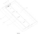
FIG. 4 is a schematic diagram of an interior of an electronic device in a drawn-out state according to an embodiment of this application; -
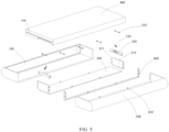
FIG. 5 is a schematic decomposition diagram of an electronic device according to an embodiment of this application; -
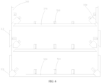
FIG. 6 is a schematic diagram of motion of a first joint part, a second joint part, and a corner member according to an embodiment of this application; -
FIG. 7 is a schematic diagram of a device body of an electronic device according to an embodiment of this application; -
FIG. 8 is an enlarged diagram of a part A inFIG. 7 ; and -
FIG. 9 is a schematic decomposition diagram of a limiting groove and a hook part according to an embodiment of this application. - Reference numerals:
- 100: first housing;
- 200: second housing;
- 300: joint housing component; 310: first joint part; 311: hook part; 320: second joint part; 330: corner member; and 331: engagement surface;
- 400: device body; and 410: guide slot;
- 510: first elastic member; 511: fixed part; and 512: curved part;
- 520: actuating motor; 530: lead screw; and 540: screw bushing;
- 600: connection member; 610: limiting protrusion; 611: limiting groove; and 612: limiting column;
- 700: second elastic member; and
- 800: guide surface.
- The following clearly describes technical solutions in embodiments of this application with reference to the accompanying drawings in the embodiments of this application. Clearly, the described embodiments are some of but not all the embodiments of this application. All other embodiments obtained by a person of ordinary skill in the art based on the embodiments of this application shall fall within the protection scope of this application.
- The terms "first", "second", and the like in the description and the claims of this application are used to distinguish between similar objects instead of describing a specific order or sequence. It should be understood that data used in such a way are interchangeable in proper circumstances, so that the embodiments of this application can be implemented in an order other than the order illustrated or described herein. Objects classified by "first", "second", and the like are usually of a same type, and a quantity of objects is not limited. For example, there may be one or more first objects. In addition, in the description and the claims, "and/or" represents at least one of connected objects, and a character "/" generally represents an "or" relationship between associated objects.
- With reference to the accompanying drawings, an electronic device provided in the embodiments of this application will be described in detail by using specific examples and application scenarios thereof.
- Refer to
FIG. 1 to FIG. 9 . An electronic device disclosed in the embodiments of this application includes afirst housing 100, asecond housing 200, a display screen, and firstjoint parts 310. Thefirst housing 100 and thesecond housing 200 are basic members of the electronic device and can provide a basis for mounting some functional components of the electronic device, for example, for mounting a main structure of the electronic device onto thefirst housing 100. The main structure includes a display screen, a circuit board, a battery, a camera lens, and the like. - In the embodiments, the display screen is disposed on the
first housing 100 and thesecond housing 200. The display screen may be a flexible screen. Optionally, an edge of the display screen is connected to thefirst housing 100 and is also connected to thesecond housing 200. - The
first housing 100 and thesecond housing 200 may move relative to each other along a first direction. Along with relative motion of the two housings, thefirst housing 100 and thesecond housing 200 becomes farther from each other. A gap is formed between thefirst housing 100 and thesecond housing 200, and the gap becomes increasingly larger, with a size of the display screen becoming larger. Optionally, thefirst housing 100 and thesecond housing 200 may move relative to each other along a direction opposite to the first direction. In this case, along with relative motion of the two housings, thefirst housing 100 and thesecond housing 200 becomes closer to each other. The gap between thefirst housing 100 and thesecond housing 200 becomes smaller, with the size of the display screen becoming smaller. - The first
joint parts 310 may move relative to thefirst housing 100 and thesecond housing 200. A moving direction is a second direction. The second direction is perpendicular to the first direction, and the first direction and the second direction both are parallel to a plane on which the display screen is located. In addition, the firstjoint parts 310 corresponds to a lateral wall of thefirst housing 100 and a lateral wall of thesecond housing 200. - Optionally, the first
joint parts 310 may be connected to thesecond housing 200 and move with thesecond housing 200 relative to thefirst housing 100. The first joint parts may alternatively be connected to neither thefirst housing 100 nor thesecond housing 200. In other words, the firstjoint parts 310 can move or stay standstill in the second direction and stay fixed in the first direction. - Any case in which the first
joint parts 310 can fill a gap between the lateral wall of thefirst housing 100 and the lateral wall of thesecond housing 200 can meet a requirement. There are a drawn-out state and a drawn-back state of the electronic device. When the drawn-back state of the electronic device is switched to the drawn-out state, thefirst housing 100 and thesecond housing 200 become farther from each other along the first direction. In this case, a gap is formed between the lateral wall of thefirst housing 100 and the lateral wall of thesecond housing 200. In this case, the firstjoint parts 310 move relative to thefirst housing 100 and thesecond housing 200 along the second direction, to join the lateral wall of thefirst housing 100 and the lateral wall of thesecond housing 200. In other words, the firstjoint parts 310 move to the gap, and an edge of the firstjoint parts 310 is in contact with an edge of the lateral wall of thefirst housing 100 and is also in contact with an edge of the lateral wall of thesecond housing 200, to fill the gap. As shown inFIG. 3 andFIG. 4 , the electronic device switches to the drawn-out state, and thefirst housing 100, thesecond housing 200, the firstjoint parts 310 form a first accommodating space together. - With such disposition, the first
joint parts 310 can fill the gap between the lateral wall of thefirst housing 100 and the lateral wall of thesecond housing 200, to ensure evenness of the appearance of the electronic device, provide an electronic device with a better look and better user experience, and with no gap, dust and stuff can be prevented from entering the electronic device, avoiding affecting a service life of the electronic device. - Optionally, the electronic device can switch from the drawn-out state to the drawn-back state. In a process in which the drawn-out state of the electronic device is switched to the drawn-back state, as the first
joint parts 310 at the gap prevent thefirst housing 100 and thesecond housing 200 from becoming closer to each other, the firstjoint parts 310 need to return to an original position along a direction opposite to the second direction, so that the firstjoint parts 310 leave the gap, to stop preventing thefirst housing 100 and thesecond housing 200 from becoming closer to each other. After the firstjoint parts 310 leave the gap, thefirst housing 100 and thesecond housing 200 can become closer to each other along the direction opposite to the first direction, until thefirst housing 100 and thesecond housing 200 are in contact with each other face to face, to achieve the drawn-back state. - In the embodiments, the first
joint parts 310 are connected on one side that is of thesecond housing 200 and that is closer to thefirst housing 100, and therefore, the firstjoint parts 310 may move with thesecond housing 200 relative to thefirst housing 100. In a process in which thefirst housing 100 and thesecond housing 200 becomes closer to each other, because the first j ointparts 310 move with thesecond housing 200 relative to thefirst housing 100, the firstjoint parts 310 are finally accommodated in thefirst housing 100, until thefirst housing 100 and thesecond housing 200 move relative to each other to a position where the two housings come in contact with each other. As shown inFIG. 1 andFIG. 2 , the electronic device switches to a second drawn-back state. In this case, thefirst housing 100 and thesecond housing 200 form a second accommodating space. A volume of the first accommodating space is greater than a volume of the second accommodating space. - In a further technical solution, as shown in
FIG. 2 , the electronic device includes a secondjoint part 320. The secondjoint part 320 may move relative to thefirst housing 100 and thesecond housing 200. A moving direction is a third direction. The third direction is perpendicular to the first direction, and the third direction is perpendicular to the plane on which the display screen is located. It indicates that the third direction is also perpendicular to the second direction. In addition, the secondjoint part 320 corresponds to a bottom wall of thefirst housing 100 and a bottom wall of thesecond housing 200. - In a process in which the drawn-back state of the electronic device is switched to the drawn-out state, the
first housing 100 and thesecond housing 200 become farther from each other along the first direction, and there is also a gap between the bottom wall of thefirst housing 100 and the bottom wall of thesecond housing 200. When the firstjoint parts 310 move along the second direction, the secondjoint part 320 moves along the third direction, so that the secondjoint part 320 joins the bottom wall of thefirst housing 100 and the bottom wall of thesecond housing 200. In other words, in a joined state, an edge of the secondjoint part 320 is in contact with an edge of the bottom wall of thefirst housing 100 and is also in contact with an edge of the bottom wall of thesecond housing 200, to fill the gap between the bottom wall of thefirst housing 100 and the bottom wall of thesecond housing 200. - Optionally, the second
joint part 320 may be connected to thesecond housing 200, to move with thesecond housing 200 relative to thefirst housing 100. The secondjoint part 320 may alternatively be connected to neither thefirst housing 100 nor thesecond housing 200. In other words, the secondjoint part 320 moves or stays standstill in the third direction and stays fixed in the first direction. Any case in which the gap is formed between the bottom wall of thefirst housing 100 and the bottom wall of the second housing in a process in which thefirst housing 100 and thesecond housing 200 becomes farther from each other, but the secondjoint part 320 can fill the gap between the bottom wall of thefirst housing 100 and the bottom wall of thesecond housing 200 can meet a requirement. - With such disposition, the second
joint part 320 can be used to further fill the gap at the bottom walls of the housings of the electronic device, to further provide the electronic device with a better look and further provide better user experience; and to reduce the gap to a larger degree to reduce a possibility that a foreign matter enters the electronic device. - In the embodiments, there are two first
joint parts 310 and one secondjoint part 320. The firstjoint parts 310 are correspondingly connected to the lateral wall of thesecond housing 200. The secondjoint part 320 is correspondingly connected to the bottom wall of thesecond housing 200. The two firstjoint parts 310 are respectively located on two ends of the secondjoint part 320 along the second direction. - With such disposition, the two first
joint parts 310 and the secondjoint part 320 can be used to fill the gap between thefirst housing 100 and thesecond housing 200 of the electronic device to a larger degree, to further provide the electronic device with a better look and further provide better user experience; and to reduce the gap to a larger degree to reduce a possibility that a foreign matter enters the electronic device. - Optionally, as shown in
FIG. 5 , the electronic device includes adevice body 400. Thedevice body 400 is equivalent to the main structure mentioned above. Thedevice body 400 is fixedly disposed on thefirst housing 100. Exactly, when the electronic device is in the drawn-out state, thedevice body 400 is disposed in the first accommodating space, and when the electronic device is in the drawn-back state, thedevice body 400 is disposed in the second accommodating space. - In this way, the
device body 400 can be used to achieve various functions of the electronic device such as displaying an image, playing a sound, and photographing. - A force for moving the first
joint parts 310 and the secondjoint part 320 may be provided manually. That is, the firstjoint parts 310 are pushed manually to move along the second direction, and the secondjoint part 320 is pushed manually to move along the third direction. In addition, to steadily dispose the firstjoint parts 310 and the secondjoint part 320 at the gap, the edges of the first j ointparts 310 and the second j ointpart 320 may be connected to an opening at an end of thefirst housing 100 by using a snap-fit structure. Clearly, another detachable connection manner may alternatively be used. Anyway, the firstjoint parts 310 and the secondjoint part 320 can move relative to thesecond housing 200 with a manual action. However, in any manner, a manual action requires more labor, and the electronic device takes a relatively long time to switch between the drawn-back state and the drawn-out state with low switching efficiency. - To resolve the foregoing problem, the electronic device further includes a first actuating mechanism. The first actuating mechanism may be directly disposed on the
first housing 100. In the embodiments, the first actuating mechanism is disposed on thedevice body 400 and is indirectly disposed on thefirst housing 100. When the electronic device is in the drawn-out state, the first actuating mechanism actuates at least one of the firstjoint parts 310 and the secondjoint part 320 to move. Specifically, the first actuating mechanism may actuate the firstjoint parts 310 to move along the second direction, may actuate the secondjoint part 320 to move along the third direction, or may actuate the firstjoint parts 310 to move along the second direction and the secondjoint part 320 to move along the third direction at the same time. - Optionally, the first actuating mechanism may be an actuating member, for example, a linear actuator, or a cylinder. One end of the first actuating mechanism is connected to the
device body 400, and the other end acts on the firstjoint parts 310 or the secondjoint part 320. The first actuating mechanism actuates the firstjoint parts 310 to move along the second direction, or actuates the secondjoint part 320 to move along the third direction. A force for returning the firstjoint parts 310 or the secondjoint part 320 to an original position may be provided manually by pushing, as directly pushing the firstjoint parts 310 or the secondjoint part 320 manually from outside thefirst housing 100 and thesecond housing 200 is relatively labor-saving. Clearly, in another embodiment, the other end of the first actuating mechanism may be connected to the firstjoint parts 310 or the secondjoint part 320, and the first actuating mechanism directly actuates the firstjoint parts 310 or the secondjoint part 320 to move and return to an original position. - Optionally, as shown in
FIG. 7 , the first actuating mechanism includes firstelastic members 510. The firstelastic members 510 are fixedly disposed on a surface of thedevice body 400. The firstelastic members 510 and thedevice body 400 may be fixedly connected to each other by welding, bonding, or the like. - When the electronic device is in the drawn-back state, the first
elastic members 510 are compressed between thedevice body 400 and an inner wall of thesecond housing 200. In this case, the firstelastic members 510 accumulates elastic potential energy and prepares for subsequently pushing the firstjoint parts 310 or the secondjoint part 320 to move. When the electronic device is in the drawn-out state, because the firstelastic members 510 is at a fixed position relative to thedevice body 400, that is, at a fixed position relative to thefirst housing 100, as thesecond housing 200 moves relative to thefirst housing 100, the firstelastic members 510 no longer act on thesecond housing 200, and the firstelastic members 510 act on the firstjoint parts 310 or the secondjoint part 320. In this case, the firstjoint parts 310 or the secondjoint part 320 cannot resist the tendency of deformation recovery of the firstelastic members 510, and the firstelastic members 510 has elastic deformation recovery. The firstelastic members 510 pushes the firstjoint parts 310 or the secondjoint part 320 to move. - With such disposition, the elastic potential energy of the first
elastic members 510 is used as an actuating force, with no need to use an electric, pneumatic, or manual power source, so that the implementation is more energy-saving, more convenient, and simpler. - Optionally, the first actuating mechanism includes a plurality of first
elastic members 510. The firstjoint parts 310 and the secondjoint part 320 both correspond to the firstelastic members 510. To be specific, the bottom and two sides of thedevice body 400 are all disposed with the firstelastic members 510, and the firstjoint parts 310 and the secondjoint part 320 each correspond to at least one of the firstelastic members 510. In the embodiments, the firstelastic members 510 may be elastic sheets, but is not limited to elastic sheets. - As shown in
FIG. 2 andFIG. 4 , each of the firstjoint parts 310 and the secondjoint part 320 corresponds to at least two firstelastic members 510. The at least two firstelastic members 510 form one group. The at least two firstelastic members 510 are spaced from each other along a direction in which thefirst housing 100 and thesecond housing 200 moves relative to each other, to push a same joint part together to move. In the embodiments, each of the firstjoint parts 310 and the secondjoint part 320 corresponds to two elastic sheets. - With such disposition, each first
elastic member 510 corresponds to one point of action, and at least two firstelastic members 510 provide a same joint part with at least two points of action, so that the firstjoint parts 310 and the secondjoint part 320 both can move steadily. - In a further technical solution, as shown in
FIG. 6 , the electronic device further includes acorner member 330. Thecorner member 330 is located between the firstjoint parts 310 and the secondjoint part 320 that are adjacent to each other. The first actuating mechanism further includes an actuating component. The actuating component is disposed on thedevice body 400. The actuating component is connected to thecorner member 330. The actuating component can actuate thecorner member 330 to move straight. - When the electronic device is in the drawn-back state, the actuating component actuates the
corner member 330 to move to an inner surface of the firstjoint parts 310 and the secondjoint part 320 that are adjacent to each other. When the electronic device is in the drawn-out state, a gap is formed between the firstjoint parts 310 and the secondjoint part 320 that are adjacent to each other. The actuating component actuates thecorner member 330 to move to the gap, and thecorner member 330 are in contact with both the firstjoint parts 310 and the secondjoint part 320. - It should be noted that, when the electronic device switches from the drawn-out state to the drawn-back state, the actuating component first needs to move the
corner member 330 from the gap to an original position, and the firstjoint parts 310 and the secondjoint part 320 are not blocked by thecorner member 330, so that the electronic device can resume movement. - With such disposition, the
corner member 330 can be used to further seal the gap between the firstjoint parts 310 and the secondjoint part 320, so that when the electronic device is in the drawn-out state, the firstjoint parts 310, the secondjoint part 320, and thecorner member 330 can completely fill the gap between thefirst housing 100 and thesecond housing 200, to provide the electronic device with a better look and better user experience to a largest degree and stop a foreign matter from entering the electronic device. - Optionally, the actuating component may be an actuating member, for example, a linear actuator, or a cylinder. One end of the actuating component is connected to the
device body 400, and the other end of the actuating component is connected to thecorner member 330, to move thecorner member 330 for back-and-forth motion. - In the embodiments, as shown in
FIG. 4 , the actuating component includes anactuating motor 520, alead screw 530, and ascrew bushing 540. A housing of theactuating motor 520 is fixedly disposed on a surface of thedevice body 400. A power take-off shaft of theactuating motor 520 is connected to thelead screw 530. Thelead screw 530 is in a screw-thread fit with thescrew bushing 540, and thecorner member 330 is connected to thescrew bushing 540. The housing of theactuating motor 520 and thedevice body 400 may be fixedly connected to each other by welding, bonding, or the like. In this way, the power take-off shaft of theactuating motor 520 actuates thelead screw 530 to rotate. As thelead screw 530 and thescrew bushing 540 are in a running fit in a rotation direction, thescrew bushing 540 can move thecorner member 330 to move along an axial direction of thelead screw 530, to finally move thecorner member 330. The foregoing structure can use the actuating component as a lead screw actuating mechanism, and the lead screw actuating mechanism has an advantage of high actuating precision to achieve precise actuation. - In the embodiments, the first
elastic members 510 are elastic sheets. As shown inFIG. 8 , each elastic sheet includes afixed part 511 and acurved part 512. Thefixed part 511 is fixedly disposed on a surface of thedevice body 400, that is, indirectly disposed on thefirst housing 100. Clearly, thefixed part 511 may alternatively be directly disposed on thefirst housing 100. When the electronic device is in a drawn-back state, thecurved part 512 acts on the inner wall of thesecond housing 200. When the electronic device is in the drawn-out state, thecurved part 512 acts on the corresponding firstjoint parts 310 or secondjoint part 320. - In an optional embodiment, a pressure sensing element is encapsulated in the
curved part 512. When actual pressure that is taken by the firstelastic members 510 and that is sensed by the pressure sensing element is greater than a preset threshold, it indicates that the corresponding firstjoint parts 310 or secondjoint part 320 may have a foreign matter or have got stuck. In this case, the electronic device sends alarm information to indicate an exception during a switching process of the electronic device and prompt a user to stop a switching action. In this case, thecorner member 330 stops moving. Specifically, the electronic device further includes a control apparatus. The control apparatus is electrically connected to the pressure sensing element and theactuating motor 520. When actual pressure sensed by the pressure sensing element is greater than the preset threshold, the control apparatus controls theactuating motor 520 to stop working and further makes thecorner member 330 stop moving. - It should be noted that the "preset threshold" does not mean a fixed numerical value but can be set based on a requirement of the user.
- With such disposition, pressure sensing information of the pressure sensing element is used to indicate whether a moving process of the first j oint
parts 310 or the secondjoint part 320 is normal, and whether thecorner member 330 needs to continue to move is controlled based on the information, to prevent an exception that causes damage to the electronic device. - In the embodiments, the pressure sensing element may be a pressure sensor. The pressure sensor is encapsulated in elastic sheets, and pressure taken by the elastic sheets can be monitored in real time through piezoresistive effect. However, the pressure sensing element is not limited to the pressure sensor, and may be another element for pressure sensing.
- Optionally, as shown in
FIG. 6 , thecorner member 330 includes anengagement surface 331. When thecorner member 330 moves to the gap between the firstjoint parts 310 and the secondjoint part 320, a first edge of theengagement surface 331 is connected to an outer surface of one of the firstjoint parts 310, and a second edge of theengagement surface 331 is connected to an outer surface of the secondjoint part 320. - In the embodiments, the first
joint parts 310 and the secondjoint part 320 both are platy and perpendicular to each other. Theengagement surface 331 further includes two connection surfaces that are perpendicular to each other. One of the connection surfaces is correspondingly connected to the outer surface of the firstjoint parts 310, the other connection surface is correspondingly connected to the outer surface of the secondjoint part 320. In other words, one of the connection surfaces is on a same plane as the outer surface of the firstjoint parts 310, the other connection surface is on a same plane as the outer surface of the secondjoint part 320. - With such disposition, the first
joint parts 310, the secondjoint part 320, and thecorner member 330 fit into each other, to fill the gap between thefirst housing 100 and thesecond housing 200 together, so that an outer surface of the electronic device is more even, and there are no bumps and lumps when adjacent parts fit into each other, to further improve user experience. - In a further technical solution, as shown in
FIG. 2 andFIG. 4 , the electronic device further includes aconnection member 600. Theconnection member 600 is movably disposed on an inner wall of thefirst housing 100 along the first direction, that is, along a direction in which thefirst housing 100 and thesecond housing 200 move relative to each other. Theconnection member 600 is connected to the firstjoint parts 310 and the secondjoint part 320, so that theconnection member 600, the firstjoint parts 310, the secondjoint part 320, and thesecond housing 200 move relative to thefirst housing 100 together. Theconnection member 600 and thesecond housing 200 are located on two sides of the firstjoint parts 310 respectively, and are also located on two sides of the secondjoint part 320 respectively. In addition, the firstjoint parts 310 may move relative to theconnection member 600 along the second direction, and the secondjoint part 320 may move relative to theconnection member 600 along the third direction. In the embodiments, theconnection member 600 is a bar-type structure member, and the bar-type structure member is correspondingly connected to the two firstjoint parts 310 and the secondjoint part 320. - Optionally, there is an interspace between the surface of the
device body 400 and the inner wall of thefirst housing 100. Theconnection member 600 is located in the interspace, so that theconnection member 600 can move along the inner wall of thefirst housing 100. - With such disposition, the
connection member 600 can connect ends that are of the firstjoint parts 310 and the secondjoint part 320 and that are farther away from thesecond housing 200, to improve synchrony of various joint parts in a process in which the firstjoint parts 310 and the secondjoint part 320 move with thesecond housing 200, to further improve steadiness of the electronic device during switching. - In an optional embodiment, at least one of the
second housing 200 and theconnection member 600 is disposed with a limitingprotrusion 610. In other words, the limitingprotrusion 610 may be disposed on the inner wall of thesecond housing 200, the limitingprotrusion 610 may be disposed on theconnection member 600, or limitingprotrusions 610 may be disposed on both the inner wall of thesecond housing 200 and theconnection member 600. The limitingprotrusion 610 is provided with a limitinggroove 611. Specifically, when the limitingprotrusion 610 corresponds to the firstjoint parts 310, the limitinggroove 611 faces the firstjoint parts 310, or when the limitingprotrusion 610 corresponds to the secondjoint part 320, the limitinggroove 611 faces the secondjoint part 320. - In the embodiments, a
hook part 311 is provided on an edge of each of the firstjoint parts 310 and the secondjoint part 320, the limitinggroove 611 is in one-to-one correspondence with thehook part 311, thehook part 311 reaches inside the corresponding limitinggroove 611, and thehook part 311 is in contact for limiting with both ends of the limitinggroove 611 along a direction in which the firstjoint parts 310 or the secondjoint part 320 move relative to thesecond housing 200. Specifically, ahook part 311 that is located at an edge of the firstjoint parts 310 is in contact along the second direction for limiting with a first end of the limitinggroove 611; and ahook part 311 that is located at an edge of the firstjoint parts 310 is in contact along the direction opposite to the second direction for limiting with a second end of the limitinggroove 611. Ahook part 311 that is located at an edge of the secondjoint part 320 is in contact along the third direction for limiting with the first end of the limitinggroove 611; and ahook part 311 that is located at an edge of the secondjoint part 320 is in contact along a direction opposite to the third direction for limiting with the second end of the limitinggroove 611. - In another embodiment, a
hook part 311 may be disposed on the edge of the firstjoint parts 310, or ahook part 311 may be disposed on the edge of the secondjoint part 320. - With such disposition, in a process in which the first
joint parts 310 and the secondjoint part 320 move relative to thesecond housing 200, acorresponding hook part 311 synchronously moves in the limitinggroove 611. In addition, the limitinggroove 611 is used to limit a moving distance of thehook part 311, to prevent the first j ointparts 310 and the secondjoint part 320 from moving too far. - In the embodiments, as shown in
FIG. 2 andFIG. 4 , the limitingprotrusions 610 are disposed on both the inner wall of thesecond housing 200 and theconnection member 600, and hookparts 311 are disposed on two sides of both the firstjoint parts 310 and the secondjoint part 320 along the direction in which thefirst housing 100 move relative to thesecond housing 200, that is, along the first direction. Thehook parts 311 are in one-to-one correspondence with the limitingprotrusions 610. - Optionally, as shown in
FIG. 9 , a secondelastic member 700 is disposed inside the limitinggroove 611. The secondelastic member 700 is used to drive thehook part 311 to move, that is, used to drive the first j ointparts 310 or the second j ointpart 320 to return to the original position, and the secondelastic member 700 is compressed between thehook part 311 and a wall of the limitinggroove 611. In the embodiments, the secondelastic member 700 may be a spring, but is not limited to the spring. - Optionally, regardless of that the electronic device is in the drawn-out state or the drawn-back state, the elastic member is compressed between the
hook part 311 and the wall of the limitinggroove 611. To be specific, a degree of compression of the secondelastic member 700 when the electronic device is in the drawn-out state is greater than a degree of compression of the secondelastic member 700 when the electronic device is in the drawn-back state. - In this way, in any state, the second
elastic member 700 accumulates elastic potential energy. When the electronic device is in the drawn-back state, because of elastic effect of the secondelastic member 700, thehook part 311 is pressed against the wall of the limitinggroove 611, and thehook part 311 is held in between the secondelastic member 700 and the wall of the limitinggroove 611, to connect the firstjoint parts 310 and thesecond housing 200 and connect the secondjoint part 320 and thesecond housing 200, so that the firstjoint parts 310 and the secondjoint part 320 can move with thesecond housing 200 relative to thefirst housing 100. Similarly, with this structure, the firstjoint parts 310 can be connected to theconnection member 600, and the secondjoint part 320 can be connected to theconnection member 600, so that theconnection member 600 can move with the firstjoint parts 310 and the secondjoint part 320 relative to thefirst housing 100. - With such disposition, the second
elastic member 700 can drive a corresponding first j ointpart 310 or secondjoint part 320 to return to the original position, saving an electric, pneumatic, or manual force for pushing, so that switching of the electric device from the drawn-out state to the drawn-back state is relatively labor-saving. - Clearly, in another embodiment, another actuating member for actuating the
hook part 311 to move, for example, a cylinder, a linear actuator, or another actuating member that can actuate to move straight, may alternatively be disposed in the limitinggroove 611. - Optionally, a limiting structure is disposed inside the limiting
groove 611. The limiting structure fits into the secondelastic member 700 for limiting along the direction in which thefirst housing 100 and thesecond housing 200 move relative to each other, that is, along the first direction. In other words, the limiting structure is used to limit the secondelastic member 700 in the limitinggroove 611, to prevent the secondelastic member 700 from getting out of the limitinggroove 611. Specifically, the limiting structure may be a protrusion structure. The protrusion structure is disposed on a side that is of the secondelastic member 700 and that is closer to an opening of the limitinggroove 611, to stop the secondelastic member 700 from getting out of the limitinggroove 611. - In the embodiments, as shown in
FIG. 9 , the secondelastic member 700 is a spring, the limiting structure is a limitingcolumn 612, and the spring is sleeved around the limitingcolumn 612. In this way, the spring can also be limited, to prevent the spring from getting out of the limitinggroove 611. - In another embodiment, a limiting structure may not be disposed inside the limiting
groove 611. An end of the spring is connected to the wall of the limitinggroove 611 by welding, bonding, or the like, and the spring can also be prevented from getting out of the limitinggroove 611. - In an optional embodiment, as shown in
FIG. 7 , the surface of thedevice body 400 is provided withguide slots 410. A guide direction of theguide slots 410 is the same as the direction in which thefirst housing 100 and thesecond housing 200 move relative to each other. In other words, the guide direction is the first direction. The limitingprotrusions 610 reach inside theguide slots 410, and the limitingprotrusions 610 fit into theguide slots 410 slidably. In this way, theguide slots 410 can guide a direction in which thesecond housing 200 and theconnection member 600 move relative to thefirst housing 100, to ensure a steady motion process and avoid deviation of the moving direction. - Specifically, the surface of the
device body 400 is provided with a plurality ofguide slots 410, and a quantity of theguide slots 410 is the same as a quantity of limitingprotrusions 610 on the inner wall of thesecond housing 200, with the guide slots in one-to-one correspondence with the limiting protrusions. In addition, the quantity of theguide slots 410 is the same as a quantity of limitingprotrusions 610 on theconnection member 600, with the guide slots in one-to-one correspondence with the limiting protrusions. In the embodiments, a limitingprotrusion 610 on the inner wall of thesecond housing 200 and a limitingprotrusion 610 on theconnection member 600 may reach inside a same guide slot at the same time. - In addition, limiting
protrusions 610 on theconnection member 600 are limited bydifferent guide slots 410, so that theconnection member 600 does not get out from between thedevice body 400 and thefirst housing 100, to prevent the firstjoint parts 310 and the secondjoint part 320 from getting out of thefirst housing 100 completely. - In a further technical solution, as shown in
FIG. 2 ,FIG. 4 , andFIG. 8 , at least one of a first end surface of thefirst housing 100 and a second end surface of the firstjoint parts 310 is aguide surface 800. The first end surface is an end surface that is of thefirst housing 100 and that is closer to thesecond housing 200, and the second end surface is an end surface that is of the firstjoint parts 310 and that is farther away from thesecond housing 200. Specifically, the first end surface of thefirst housing 100 may be disposed as theguide surface 800, the second end surface of the firstjoint parts 310 may be disposed as theguide surface 800, or both the first end surface and the second end surface may be disposed as guide surfaces. - In the embodiments, both the first end surface and the second end surface may be disposed as the guide surfaces 800. The guide surfaces 800 are inclined surfaces. The
guide surface 800 on the first end surface cooperates with theguide surface 800 on the second end surface. - Similarly, a third end surface of the second
joint part 320 is further disposed as theguide surface 800. The third end surface is an end surface that is of the secondjoint part 320 and that is farther away from thesecond housing 200. Theguide surface 800 on the third end surface also cooperates with theguide surface 800 on the first end surface. In this way, along the guide directions of the guide surfaces 800, the firstjoint parts 310 can move in the direction opposite to the second direction, and the secondjoint part 320 can move in the direction opposite to the third direction, that is, to facilitate the firstjoint parts 310 and the secondjoint part 320 to return to the original position. - With such disposition, when the electronic device is in the drawn-out state, an external force is used to push the
first housing 100 or thesecond housing 200, so that thefirst housing 100 and thesecond housing 200 become closer to each other. Specifically, when the external force is used to push thesecond housing 200, the firstjoint parts 310 and the secondjoint part 320 take an acting force close to thefirst housing 100; and when the external force is used to push thefirst housing 100, thefirst housing 100 takes an acting force close to the firstjoint parts 310 and the secondjoint part 320. - In any case, the first
joint parts 310 and the secondjoint part 320 become closer to thefirst housing 100 along the guide surfaces 800. In a process of becoming closer, the first end surface gives a component of force along the direction opposite to the second direction to the firstjoint parts 310, and gives a component of force along the direction opposite to the third direction to the secondjoint part 320, to push the firstjoint parts 310 and the secondjoint part 320 to return to the original position, with no need to apply an extra external force on the firstjoint parts 310 and the secondjoint part 320, so that a switching process is more labor-saving and more convenient. - The embodiments of this application are described above with reference to the accompanying drawings, but this application is not limited to the foregoing specific implementations, and the foregoing specific implementations are only illustrative and not restrictive. Enlightened by this application, a person of ordinary skill in the art can make many forms without departing from the purpose of this application and the protection scope of the claims, all of which fall within the protection of this application.
Claims (13)
- An electronic device, comprising a first housing, a second housing, a display screen, and a first joint part, whereinthe display screen is disposed on the first housing and the second housing, there are a drawn-out state and a drawn-back state of the electronic device, and when the drawn-back state of the electronic device is switched to the drawn-out state, the first housing and the second housing become farther from each other along a first direction, and the first joint part moves along a second direction to join a lateral wall of the first housing and a lateral wall of the second housing; andthe first direction is perpendicular to the second direction, and the first direction and the second direction both are parallel to a plane on which the display screen is located.
- The electronic device according to claim 1, wherein the electronic device further comprises a second joint part, and when the drawn-back state of the electronic device is switched to the drawn-out state, the second joint part moves along a third direction to join a bottom wall of the first housing and a bottom wall of the second housing; and the third direction is perpendicular to the first direction, and the third direction is perpendicular to the plane on which the display screen is located.
- The electronic device according to claim 2, wherein the electronic device further comprises a first actuating mechanism, the first actuating mechanism is disposed on the first housing, and when the electronic device is in the drawn-out state, the first actuating mechanism actuates at least one of the first j oint part and the second j oint part to move.
- The electronic device according to claim 3, wherein the first actuating mechanism comprises a first elastic member, andwhen the electronic device is in the drawn-back state, the first elastic member is compressed between the first housing and the second housing; orwhen the electronic device is in the drawn-out state, the first elastic member recovers with elastic deformation and acts on the first j oint part or the second j oint part.
- The electronic device according to claim 4, wherein the first elastic member is an elastic sheet, the elastic sheet comprises a fixed part and a curved part, the fixed part is disposed on the first housing, and when the electronic device is in the drawn-back state, the curved part acts on the second housing, or when the electronic device is in the drawn-out state, the curved part acts on the first joint part or the second joint part; and a pressure sensing element is encapsulated in the curved part, wherein when actual pressure sensed by the pressure sensing element is greater than a preset threshold, the electronic device sends alarm information.
- The electronic device according to claim 2, wherein the electronic device further comprises a corner member and an actuating component, the actuating component is disposed on the first housing, and the actuating component is connected to the corner member, whereinwhen the electronic device is in the drawn-back state, the actuating component actuates the corner member to move to an inner surface of the first joint part and the second joint part that are adj acent to each other; orwhen the electronic device is in the drawn-out state, a gap is formed between the first joint part and the second joint part that are adjacent to each other, the actuating component actuates the corner member to move to the gap, and the corner member is in contact with both the first joint part and the second joint part.
- The electronic device according to claim 6, wherein the actuating component comprises an actuating motor, a lead screw, and a screw bushing, a housing of the actuating motor is disposed on the first housing, a power take-off shaft of the actuating motor is connected to the lead screw, the lead screw is in a screw-thread fit with the screw bushing, and the corner member is connected to the screw bushing.
- The electronic device according to claim 6, wherein the corner member comprises an engagement surface, and when the corner member moves to the gap, a first edge of the engagement surface is connected to an outer surface of the first joint part, and a second edge of the engagement surface is connected to an outer surface of the second joint part.
- The electronic device according to claim 2, wherein the electronic device further comprises a connection member, the connection member is movably disposed on an inner wall of the first housing along the first direction, the first j oint part and the second j oint part both are connected to the second housing, the connection member is connected to the first joint part and the second j oint part, the first j oint part is capable of moving relative to the connection member along the second direction, and the second joint part is capable of moving relative to the connection member along the third direction.
- The electronic device according to claim 9, wherein at least one of the second housing and the connection member is disposed with a limiting protrusion, the limiting protrusion is provided with a limiting groove, a hook part is provided on an edge of each of the first joint part and the second joint part, the limiting groove is in one-to-one correspondence with the hook part, the hook part reaches inside the corresponding limiting groove, and the hook part is in contact for limiting with both ends of the limiting groove along a direction in which the first joint part or the second joint part move relative to the second housing.
- The electronic device according to claim 10, wherein a second elastic member is disposed inside the limiting groove, the second elastic member is used to drive the first joint part or the second joint part to return to an original position, and the second elastic member is compressed between the hook part and a wall of the limiting groove.
- The electronic device according to claim 11, wherein a limiting structure is disposed inside the limiting groove, and the limiting structure fits into the second elastic member along a direction in which the first housing and the second housing move relative to each other.
- The electronic device according to claim 10, wherein the electronic device further comprises a device body, the device body is disposed on the first housing, the device body is provided with a guide slot, an extension direction of the guide slot is the same as the direction in which the first housing and the second housing move relative to each other, and the limiting protrusion reaches inside the guide slot and fits into the guide slot slidably.
Applications Claiming Priority (2)
| Application Number | Priority Date | Filing Date | Title |
|---|---|---|---|
| CN202111194721.7A CN113938545B (en) | 2021-10-13 | 2021-10-13 | Electronic equipment |
| PCT/CN2022/124885 WO2023061410A1 (en) | 2021-10-13 | 2022-10-12 | Electronic device |
Publications (3)
| Publication Number | Publication Date |
|---|---|
| EP4418638A1 true EP4418638A1 (en) | 2024-08-21 |
| EP4418638A4 EP4418638A4 (en) | 2025-04-16 |
| EP4418638B1 EP4418638B1 (en) | 2026-01-28 |
Family
ID=79279228
Family Applications (1)
| Application Number | Title | Priority Date | Filing Date |
|---|---|---|---|
| EP22880346.6A Active EP4418638B1 (en) | 2021-10-13 | 2022-10-12 | Electronic device |
Country Status (4)
| Country | Link |
|---|---|
| US (1) | US20240267445A1 (en) |
| EP (1) | EP4418638B1 (en) |
| CN (1) | CN113938545B (en) |
| WO (1) | WO2023061410A1 (en) |
Families Citing this family (1)
| Publication number | Priority date | Publication date | Assignee | Title |
|---|---|---|---|---|
| CN113938545B (en) * | 2021-10-13 | 2023-09-22 | 维沃移动通信有限公司 | Electronic equipment |
Family Cites Families (23)
| Publication number | Priority date | Publication date | Assignee | Title |
|---|---|---|---|---|
| JP2009033620A (en) * | 2007-07-30 | 2009-02-12 | Kyocera Corp | Portable electronic devices |
| JP2010081570A (en) * | 2008-08-28 | 2010-04-08 | Kyocera Corp | Portable electronic apparatus |
| KR20160139470A (en) * | 2015-05-27 | 2016-12-07 | 엘지전자 주식회사 | Mobile terminal |
| KR102547146B1 (en) * | 2016-07-07 | 2023-06-23 | 삼성디스플레이 주식회사 | Rollable display device |
| KR102540815B1 (en) * | 2018-06-01 | 2023-06-08 | 삼성전자주식회사 | Electronic device including a foldable display |
| JP2020053001A (en) * | 2018-09-21 | 2020-04-02 | スガツネ工業株式会社 | Foldable display device and hinge device |
| CN110145535B (en) * | 2019-06-14 | 2024-03-15 | 深圳市长盈精密技术股份有限公司 | Balanced control mechanism, folding display device and communication equipment |
| CN110445913B (en) * | 2019-07-31 | 2024-07-30 | 华为技术有限公司 | Folding components and electronic devices |
| KR20210022921A (en) * | 2019-08-21 | 2021-03-04 | 삼성전자주식회사 | Sliding operated electronic device |
| CN112751951B (en) * | 2019-10-29 | 2022-03-15 | Oppo广东移动通信有限公司 | Folding devices and electronic equipment |
| KR102724991B1 (en) * | 2019-12-16 | 2024-11-04 | 삼성전자 주식회사 | Rollable electronic device including gap compensation structure between housings |
| CN113037898B (en) * | 2019-12-24 | 2022-06-14 | Oppo广东移动通信有限公司 | Housing components and electronic equipment |
| CN113037896B (en) * | 2019-12-24 | 2022-06-14 | Oppo广东移动通信有限公司 | Flexible screen components and electronic equipment |
| CN210578711U (en) * | 2019-12-26 | 2020-05-19 | 维沃移动通信有限公司 | Electronic equipment |
| CN111683166B (en) * | 2020-05-28 | 2022-02-01 | 维沃移动通信有限公司 | Electronic device |
| WO2022015048A1 (en) * | 2020-07-14 | 2022-01-20 | 삼성전자 주식회사 | Electronic device comprising rollable display |
| CN112269426B (en) * | 2020-10-20 | 2022-11-11 | 维沃移动通信有限公司 | Electronic equipment |
| EP4239444B1 (en) * | 2020-12-04 | 2025-02-26 | Samsung Electronics Co., Ltd. | Slidable electronic device |
| CN113163038B (en) * | 2021-04-25 | 2023-07-25 | 维沃移动通信有限公司 | Screen components and electronics |
| CN113301201B (en) * | 2021-05-20 | 2023-12-05 | Oppo广东移动通信有限公司 | Electronic equipment |
| CN113242343B (en) * | 2021-06-18 | 2023-08-22 | 维沃移动通信有限公司 | Electronic equipment |
| CN113452821A (en) * | 2021-07-07 | 2021-09-28 | 维沃移动通信有限公司 | Electronic equipment |
| CN113938545B (en) * | 2021-10-13 | 2023-09-22 | 维沃移动通信有限公司 | Electronic equipment |
-
2021
- 2021-10-13 CN CN202111194721.7A patent/CN113938545B/en active Active
-
2022
- 2022-10-12 EP EP22880346.6A patent/EP4418638B1/en active Active
- 2022-10-12 WO PCT/CN2022/124885 patent/WO2023061410A1/en not_active Ceased
-
2024
- 2024-04-12 US US18/634,184 patent/US20240267445A1/en active Pending
Also Published As
| Publication number | Publication date |
|---|---|
| US20240267445A1 (en) | 2024-08-08 |
| WO2023061410A1 (en) | 2023-04-20 |
| EP4418638B1 (en) | 2026-01-28 |
| CN113938545A (en) | 2022-01-14 |
| CN113938545B (en) | 2023-09-22 |
| EP4418638A4 (en) | 2025-04-16 |
Similar Documents
| Publication | Publication Date | Title |
|---|---|---|
| CN107197133B (en) | A kind of mobile terminal and CCD camera assembly | |
| CN107613060B (en) | Electronic equipment | |
| EP3211507B1 (en) | Camera assembly and electronic device | |
| US11023019B2 (en) | Mobile terminal | |
| EP4117255B1 (en) | Electronic device | |
| CN102194592A (en) | Key structure and portable electronic device with same | |
| CN111182096B (en) | Electronic equipment and method of using electronic equipment | |
| US20240267445A1 (en) | Electronic device | |
| CN110062146B (en) | Terminal Equipment | |
| US20230015804A1 (en) | Electronic device | |
| CN208445598U (en) | Electronic equipment | |
| EP3745436B1 (en) | An integrated switch | |
| KR20050105563A (en) | Slide type mobile communication terminal and automatic driving method thereof | |
| CN110518927A (en) | Electronic equipment | |
| CN115086535A (en) | Security protection camera | |
| CN106790796A (en) | Housing components and mobile terminals | |
| EP4351123A1 (en) | Camera module and electronic device | |
| CN211429356U (en) | a mobile terminal | |
| CN110518741B (en) | Electronic device | |
| CN113132592A (en) | Thin displacement driving device | |
| CN216981540U (en) | A charging docking device and a mobile robot | |
| CN213025891U (en) | A side button structure and mobile terminal | |
| CN211184006U (en) | Camera module slidable intelligent terminal | |
| CN109962995B (en) | Functional assembly, electronic device and control method thereof | |
| CN215869062U (en) | Micromotion module |
Legal Events
| Date | Code | Title | Description |
|---|---|---|---|
| STAA | Information on the status of an ep patent application or granted ep patent |
Free format text: STATUS: THE INTERNATIONAL PUBLICATION HAS BEEN MADE |
|
| PUAI | Public reference made under article 153(3) epc to a published international application that has entered the european phase |
Free format text: ORIGINAL CODE: 0009012 |
|
| STAA | Information on the status of an ep patent application or granted ep patent |
Free format text: STATUS: REQUEST FOR EXAMINATION WAS MADE |
|
| 17P | Request for examination filed |
Effective date: 20240409 |
|
| AK | Designated contracting states |
Kind code of ref document: A1 Designated state(s): AL AT BE BG CH CY CZ DE DK EE ES FI FR GB GR HR HU IE IS IT LI LT LU LV MC ME MK MT NL NO PL PT RO RS SE SI SK SM TR |
|
| DAV | Request for validation of the european patent (deleted) | ||
| DAX | Request for extension of the european patent (deleted) | ||
| RIC1 | Information provided on ipc code assigned before grant |
Ipc: H04M 1/18 20060101ALI20241217BHEP Ipc: H04M 1/02 20060101AFI20241217BHEP |
|
| A4 | Supplementary search report drawn up and despatched |
Effective date: 20250317 |
|
| RIC1 | Information provided on ipc code assigned before grant |
Ipc: H04M 1/18 20060101ALI20250311BHEP Ipc: H04M 1/02 20060101AFI20250311BHEP |
|
| GRAP | Despatch of communication of intention to grant a patent |
Free format text: ORIGINAL CODE: EPIDOSNIGR1 |
|
| STAA | Information on the status of an ep patent application or granted ep patent |
Free format text: STATUS: GRANT OF PATENT IS INTENDED |
|
| INTG | Intention to grant announced |
Effective date: 20251024 |
|
| GRAS | Grant fee paid |
Free format text: ORIGINAL CODE: EPIDOSNIGR3 |
|
| GRAA | (expected) grant |
Free format text: ORIGINAL CODE: 0009210 |
|
| STAA | Information on the status of an ep patent application or granted ep patent |
Free format text: STATUS: THE PATENT HAS BEEN GRANTED |
|
| AK | Designated contracting states |
Kind code of ref document: B1 Designated state(s): AL AT BE BG CH CY CZ DE DK EE ES FI FR GB GR HR HU IE IS IT LI LT LU LV MC ME MK MT NL NO PL PT RO RS SE SI SK SM TR |
|
| REG | Reference to a national code |
Ref country code: CH Ref legal event code: F10 Free format text: ST27 STATUS EVENT CODE: U-0-0-F10-F00 (AS PROVIDED BY THE NATIONAL OFFICE) Effective date: 20260128 Ref country code: GB Ref legal event code: FG4D |
|
| REG | Reference to a national code |
Ref country code: IE Ref legal event code: FG4D |
|
| REG | Reference to a national code |
Ref country code: DE Ref legal event code: R096 Ref document number: 602022029531 Country of ref document: DE |