EP4418482A1 - Zero-sequence resistive current differential protection method for inter-station tie line of small-resistance grounding system - Google Patents
Zero-sequence resistive current differential protection method for inter-station tie line of small-resistance grounding system Download PDFInfo
- Publication number
- EP4418482A1 EP4418482A1 EP22952944.1A EP22952944A EP4418482A1 EP 4418482 A1 EP4418482 A1 EP 4418482A1 EP 22952944 A EP22952944 A EP 22952944A EP 4418482 A1 EP4418482 A1 EP 4418482A1
- Authority
- EP
- European Patent Office
- Prior art keywords
- tie line
- zero
- sequence
- current
- resistive
- Prior art date
- Legal status (The legal status is an assumption and is not a legal conclusion. Google has not performed a legal analysis and makes no representation as to the accuracy of the status listed.)
- Pending
Links
Images

Classifications
-
- H—ELECTRICITY
- H02—GENERATION; CONVERSION OR DISTRIBUTION OF ELECTRIC POWER
- H02H—EMERGENCY PROTECTIVE CIRCUIT ARRANGEMENTS
- H02H7/00—Emergency protective circuit arrangements specially adapted for specific types of electric machines or apparatus or for sectionalised protection of cable or line systems, and effecting automatic switching in the event of an undesired change from normal working conditions
- H02H7/26—Sectionalised protection of cable or line systems, e.g. for disconnecting a section on which a short-circuit, earth fault, or arc discharge has occured
-
- H—ELECTRICITY
- H02—GENERATION; CONVERSION OR DISTRIBUTION OF ELECTRIC POWER
- H02H—EMERGENCY PROTECTIVE CIRCUIT ARRANGEMENTS
- H02H3/00—Emergency protective circuit arrangements for automatic disconnection directly responsive to an undesired change from normal electric working condition with or without subsequent reconnection ; integrated protection
- H02H3/26—Emergency protective circuit arrangements for automatic disconnection directly responsive to an undesired change from normal electric working condition with or without subsequent reconnection ; integrated protection responsive to difference between voltages or between currents; responsive to phase angle between voltages or between currents
- H02H3/28—Emergency protective circuit arrangements for automatic disconnection directly responsive to an undesired change from normal electric working condition with or without subsequent reconnection ; integrated protection responsive to difference between voltages or between currents; responsive to phase angle between voltages or between currents involving comparison of the voltage or current values at two spaced portions of a single system, e.g. at opposite ends of one line, at input and output of apparatus
-
- G—PHYSICS
- G01—MEASURING; TESTING
- G01R—MEASURING ELECTRIC VARIABLES; MEASURING MAGNETIC VARIABLES
- G01R31/00—Arrangements for testing electric properties; Arrangements for locating electric faults; Arrangements for electrical testing characterised by what is being tested not provided for elsewhere
- G01R31/08—Locating faults in cables, transmission lines, or networks
- G01R31/081—Locating faults in cables, transmission lines, or networks according to type of conductors
- G01R31/085—Locating faults in cables, transmission lines, or networks according to type of conductors in power transmission or distribution lines, e.g. overhead
-
- G—PHYSICS
- G01—MEASURING; TESTING
- G01R—MEASURING ELECTRIC VARIABLES; MEASURING MAGNETIC VARIABLES
- G01R31/00—Arrangements for testing electric properties; Arrangements for locating electric faults; Arrangements for electrical testing characterised by what is being tested not provided for elsewhere
- G01R31/08—Locating faults in cables, transmission lines, or networks
- G01R31/081—Locating faults in cables, transmission lines, or networks according to type of conductors
- G01R31/086—Locating faults in cables, transmission lines, or networks according to type of conductors in power transmission or distribution networks, i.e. with interconnected conductors
-
- G—PHYSICS
- G01—MEASURING; TESTING
- G01R—MEASURING ELECTRIC VARIABLES; MEASURING MAGNETIC VARIABLES
- G01R31/00—Arrangements for testing electric properties; Arrangements for locating electric faults; Arrangements for electrical testing characterised by what is being tested not provided for elsewhere
- G01R31/08—Locating faults in cables, transmission lines, or networks
- G01R31/088—Aspects of digital computing
-
- G—PHYSICS
- G01—MEASURING; TESTING
- G01R—MEASURING ELECTRIC VARIABLES; MEASURING MAGNETIC VARIABLES
- G01R31/00—Arrangements for testing electric properties; Arrangements for locating electric faults; Arrangements for electrical testing characterised by what is being tested not provided for elsewhere
- G01R31/50—Testing of electric apparatus, lines, cables or components for short-circuits, continuity, leakage current or incorrect line connections
- G01R31/52—Testing for short-circuits, leakage current or ground faults
-
- G—PHYSICS
- G01—MEASURING; TESTING
- G01R—MEASURING ELECTRIC VARIABLES; MEASURING MAGNETIC VARIABLES
- G01R31/00—Arrangements for testing electric properties; Arrangements for locating electric faults; Arrangements for electrical testing characterised by what is being tested not provided for elsewhere
- G01R31/50—Testing of electric apparatus, lines, cables or components for short-circuits, continuity, leakage current or incorrect line connections
- G01R31/58—Testing of lines, cables or conductors
-
- H—ELECTRICITY
- H02—GENERATION; CONVERSION OR DISTRIBUTION OF ELECTRIC POWER
- H02H—EMERGENCY PROTECTIVE CIRCUIT ARRANGEMENTS
- H02H1/00—Details of emergency protective circuit arrangements
- H02H1/0007—Details of emergency protective circuit arrangements concerning the detecting means
-
- H—ELECTRICITY
- H02—GENERATION; CONVERSION OR DISTRIBUTION OF ELECTRIC POWER
- H02H—EMERGENCY PROTECTIVE CIRCUIT ARRANGEMENTS
- H02H3/00—Emergency protective circuit arrangements for automatic disconnection directly responsive to an undesired change from normal electric working condition with or without subsequent reconnection ; integrated protection
- H02H3/38—Emergency protective circuit arrangements for automatic disconnection directly responsive to an undesired change from normal electric working condition with or without subsequent reconnection ; integrated protection responsive to both voltage and current; responsive to phase angle between voltage and current
- H02H3/382—Emergency protective circuit arrangements for automatic disconnection directly responsive to an undesired change from normal electric working condition with or without subsequent reconnection ; integrated protection responsive to both voltage and current; responsive to phase angle between voltage and current involving phase comparison between current and voltage or between values derived from current and voltage
-
- H—ELECTRICITY
- H02—GENERATION; CONVERSION OR DISTRIBUTION OF ELECTRIC POWER
- H02H—EMERGENCY PROTECTIVE CIRCUIT ARRANGEMENTS
- H02H3/00—Emergency protective circuit arrangements for automatic disconnection directly responsive to an undesired change from normal electric working condition with or without subsequent reconnection ; integrated protection
- H02H3/38—Emergency protective circuit arrangements for automatic disconnection directly responsive to an undesired change from normal electric working condition with or without subsequent reconnection ; integrated protection responsive to both voltage and current; responsive to phase angle between voltage and current
- H02H3/387—Emergency protective circuit arrangements for automatic disconnection directly responsive to an undesired change from normal electric working condition with or without subsequent reconnection ; integrated protection responsive to both voltage and current; responsive to phase angle between voltage and current using phase-sequence analysing arrangements
-
- H—ELECTRICITY
- H02—GENERATION; CONVERSION OR DISTRIBUTION OF ELECTRIC POWER
- H02H—EMERGENCY PROTECTIVE CIRCUIT ARRANGEMENTS
- H02H7/00—Emergency protective circuit arrangements specially adapted for specific types of electric machines or apparatus or for sectionalised protection of cable or line systems, and effecting automatic switching in the event of an undesired change from normal working conditions
- H02H7/26—Sectionalised protection of cable or line systems, e.g. for disconnecting a section on which a short-circuit, earth fault, or arc discharge has occured
- H02H7/261—Sectionalised protection of cable or line systems, e.g. for disconnecting a section on which a short-circuit, earth fault, or arc discharge has occured involving signal transmission between at least two stations
- H02H7/263—Sectionalised protection of cable or line systems, e.g. for disconnecting a section on which a short-circuit, earth fault, or arc discharge has occured involving signal transmission between at least two stations involving transmissions of measured values
-
- H—ELECTRICITY
- H02—GENERATION; CONVERSION OR DISTRIBUTION OF ELECTRIC POWER
- H02H—EMERGENCY PROTECTIVE CIRCUIT ARRANGEMENTS
- H02H7/00—Emergency protective circuit arrangements specially adapted for specific types of electric machines or apparatus or for sectionalised protection of cable or line systems, and effecting automatic switching in the event of an undesired change from normal working conditions
- H02H7/26—Sectionalised protection of cable or line systems, e.g. for disconnecting a section on which a short-circuit, earth fault, or arc discharge has occured
- H02H7/28—Sectionalised protection of cable or line systems, e.g. for disconnecting a section on which a short-circuit, earth fault, or arc discharge has occured for meshed systems
Definitions
- the present application belongs to the technical field of power system relay protection, and relates to a zero-sequence resistive-current differential protection method for an inter-station tie line of a low-resistance grounding system.
- the single-phase grounding protection for a tie line adopts full-current zero-sequence differential protection.
- the differential current between the two sides of the tie line contains the grounding capacitance current of the tie line, which is not conducive to the selectivity of single-phase differential protection and reduces the protection reliability.
- the differential current of the grounding capacitance currents of the tie line at two sides of the line is close to zero, which does not increase the differential action current.
- the amplitude of the capacitive differential current depends on the grounding capacitance currents of the power stations on two sides, that is, the amplitude of the capacitive differential current is affected by the operating mode of the power station.
- the single-phase grounding protection for the tie line adopts resistive-current zero-sequence differential protection.
- resistive-current zero-sequence differential protection when the ground resistances on two sides of the tie line are effectively enabled, the disadvantageous factors of the capacitance current during the single-phase grounding may be overcome, and the tie line is affected neither by the large unbalanced current at the external fault due to the excessive length of the tie line, nor by the operating mode of the power station.
- resistive current zero-sequence differential protection the zero-sequence differential current is the difference of vectors of resistive currents flowing through the current transformers on two sides of the tie line when single-phase grounding occurs in the tie line.
- the present application utilises the characteristics of the zero-sequence current of the tie line and adopts the relay protection method based on the principle of resistive-current zero-sequence differential protection to accurately judge whether single-phase grounding occurs in the grounded tie line in time and cut out faulty tie line.
- the present application is clear and reliable in principle, and conforms to the basic principles of relay protection, namely, reliability, sensitivity, selectivity and speed.
- the object of the present application is to overcome the above-mentioned shortcomings of the prior art, and provide a zero-sequence resistive-current differential protection method for an inter-station tie line of a low-resistance grounding system, which is capable of accurately judging whether single-phase grounding occurs in the grounded tie line in time and cutting the out faulty tie line.
- the zero-sequence resistive-current differential protection method for an inter-station tie line of a low-resistance grounding system includes the following steps:
- the present application has the following beneficial effects: when the zero-sequence resistive-current differential protection method for an inter-station tie line of a low-resistance grounding system provided by the present application is specifically operated, the zero-sequence resistive differential current I ⁇ 0dr and the braking current I ⁇ 0 s are calculated, whether a single-phase grounding fault occurs is judged according to the zero-sequence resistive differential current I ⁇ 0dr and the braking current I ⁇ 0s , and when it is determined that a single-phase grounding fault occurs, the fault is cut off in time, and when the ground resistances on two sides of the tie line are effectively enabled, the disadvantageous factors of the capacitance current during the single-phase grounding may be overcome, and the tie line is affected neither by the large unbalanced current at the external fault due to the excessive length of the tie line, nor by the operating mode of the power station.
- the zero-sequence differential current is the difference of vectors of resistive currents flowing through the current transformers on two sides of the tie line when single-phase grounding occurs in the tie line.
- the present application utilises the characteristics of the zero-sequence current of the tie line and adopts the relay protection method based on the principle of resistive-current zero-sequence differential protection to accurately judge whether single-phase grounding occurs in the grounded tie line in time and cut out faulty tie line.
- the present application is clear and reliable in principle, and conforms to the basic principles of relay protection, namely, reliability, sensitivity, selectivity and speed.
- a zero-sequence resistive-current differential protection method for an inter-station tie line of a low-resistance grounding system includes the following steps:
- Conditions of the zero-sequence differential protection action further include:
- the present application is applicable to the situation that the single-phase grounding protection for the tie line adopts the resistive current zero-sequence differential protection, and the single-phase grounding protection for the tie line is realized by modifying the protection logic and calculating the differential current.
- the fault location of the application is accurate, the delay is short, the single-phase grounding is prevented from evolving to phase-to-phase faults, the fault circuit is removed, and the single-phase grounding is effectively prevented from evolving to phase-to-phase faults.
- the present application is simple and reliable in principle, and conforms to the basic principles of relay protection, namely, reliability, sensitivity, selectivity and speed.
Landscapes
- Physics & Mathematics (AREA)
- General Physics & Mathematics (AREA)
- Engineering & Computer Science (AREA)
- Mathematical Physics (AREA)
- Theoretical Computer Science (AREA)
- Power Engineering (AREA)
- Emergency Protection Circuit Devices (AREA)
Abstract
Description
- The present application claims priority to
Chinese Patent Application No. 202210886960.7, filed to the CNIPA on July 26, 2022 - The present application belongs to the technical field of power system relay protection, and relates to a zero-sequence resistive-current differential protection method for an inter-station tie line of a low-resistance grounding system.
- As new energy sources continue to scale up, there are more and more dispersedly distributed wind power stations, photovoltaic power stations and energy storage power stations. After being connected by a tie line, multiple power stations are connected to the power grid through one power station.
- At present, the single-phase grounding protection for a tie line adopts full-current zero-sequence differential protection. When an external single-phase grounding fault occurs in the tie line, the differential current between the two sides of the tie line contains the grounding capacitance current of the tie line, which is not conducive to the selectivity of single-phase differential protection and reduces the protection reliability. When an internal single-phase grounding fault occurs in the tie line, the differential current of the grounding capacitance currents of the tie line at two sides of the line is close to zero, which does not increase the differential action current. At the same time, the amplitude of the capacitive differential current depends on the grounding capacitance currents of the power stations on two sides, that is, the amplitude of the capacitive differential current is affected by the operating mode of the power station.
- For resistance-grounded power stations, the single-phase grounding protection for the tie line adopts resistive-current zero-sequence differential protection. when the ground resistances on two sides of the tie line are effectively enabled, the disadvantageous factors of the capacitance current during the single-phase grounding may be overcome, and the tie line is affected neither by the large unbalanced current at the external fault due to the excessive length of the tie line, nor by the operating mode of the power station. With resistive current zero-sequence differential protection, the zero-sequence differential current is the difference of vectors of resistive currents flowing through the current transformers on two sides of the tie line when single-phase grounding occurs in the tie line. The present application utilises the characteristics of the zero-sequence current of the tie line and adopts the relay protection method based on the principle of resistive-current zero-sequence differential protection to accurately judge whether single-phase grounding occurs in the grounded tie line in time and cut out faulty tie line. The present application is clear and reliable in principle, and conforms to the basic principles of relay protection, namely, reliability, sensitivity, selectivity and speed.
- The object of the present application is to overcome the above-mentioned shortcomings of the prior art, and provide a zero-sequence resistive-current differential protection method for an inter-station tie line of a low-resistance grounding system, which is capable of accurately judging whether single-phase grounding occurs in the grounded tie line in time and cutting the out faulty tie line.
- In order to achieve the above object, the zero-sequence resistive-current differential protection method for an inter-station tie line of a low-resistance grounding system according to the present application includes the following steps:
- 1) acquiring three-phase currents


- 2) calculating a resistive zero-sequence current


- 3) calculating a resistive zero-sequence current


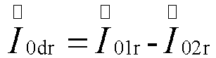
- 4) calculating a zero-sequence resistive differential current


- 5) performing a zero-sequence differential protection action when


- The resistive zero-sequence current


wherein θ is an included angle between


- The three-phase current vector


- The resistive zero-sequence current


wherein ϕ is an included angle between


- The three-phase current vector


- The zero-sequence resistive differential current


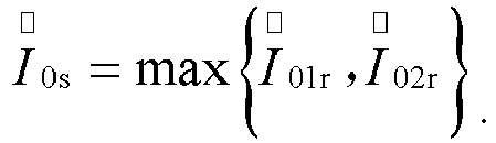
- The braking current


- The present application has the following beneficial effects:
when the zero-sequence resistive-current differential protection method for an inter-station tie line of a low-resistance grounding system provided by the present application is specifically operated, the zero-sequence resistive differential current


-
-
Fig. 1 is a schematic diagram of a single-phase grounding fault current of a resistance grounded inter-station tie line according to an embodiment of the present application; and -
Fig. 2 is a vector diagram according to an embodiment of the present application. - In order to make those skilled in the art better understand the solutions of the present application, the technical solutions in the embodiments of the present application will be clearly and completely described below in conjunction with the drawings in the embodiments of the present application. Obviously, the described embodiments are only part of, but not all of, the embodiments of the present application, and not intended to limit the scope of the disclosure of the present application. Additionally, in the following description, descriptions of well-known structures and techniques are omitted to avoid unnecessarily obscuring the concepts disclosed in the present application. Based on the embodiments in the present application, all other embodiments obtained by a person having ordinary skill in the art without making inventive labor should belong to the scope of protection of the present application.
- Structural schematic diagrams according to embodiments disclosed in the present application are shown in the accompanying drawings. The figures are not drawn to scale, with some details exaggerated and some other details omitted for the purpose of clear expression. The shapes of the various regions and layers and their relative sizes and positional relationships shown in the figures are merely exemplary, and deviations may occur in practice due to manufacturing tolerances or technical limitations, and those skilled in the art may otherwise design regions/layers having different shapes, sizes and relative positions according to actual needs.
- Referring to
Fig. 1 and Fig. 2 , a zero-sequence resistive-current differential protection method for an inter-station tie line of a low-resistance grounding system in an embodiment of the present application includes the following steps: - 1) acquiring three-phase currents


- 2) calculating a resistive zero-sequence current


wherein θ is an included angle between


- 3) calculating a resistive zero-sequence current


wherein ϕ is an included angle between


- 4) calculating a zero-sequence resistive differential current



- 5) performing a zero-sequence differential protection action when


- Conditions of the zero-sequence differential protection action further include:
- a hard strap of zero-sequence resistive-current differential protection for the tie line is enabled;
- a soft strap of zero-sequence resistive-current differential protection for the tie line is enabled;
- the grounding transformer circuit breaker of the power station at the sending end of the tie line is in a closed position;
- the grounding transformer circuit breaker of the power station at the receiving end of the tie line is in a closed position;
- the exit delay of zero-sequence differential protection of the grounding transformer is 0.1 s to 20 s, wherein the specific set value is less than the backup setting time of a neutral zero-sequence overcurrent system.
- The present application is applicable to the situation that the single-phase grounding protection for the tie line adopts the resistive current zero-sequence differential protection, and the single-phase grounding protection for the tie line is realized by modifying the protection logic and calculating the differential current. The fault location of the application is accurate, the delay is short, the single-phase grounding is prevented from evolving to phase-to-phase faults, the fault circuit is removed, and the single-phase grounding is effectively prevented from evolving to phase-to-phase faults. The present application is simple and reliable in principle, and conforms to the basic principles of relay protection, namely, reliability, sensitivity, selectivity and speed.
Claims (7)
- A zero-sequence resistive-current differential protection method for an inter-station tie line of a low-resistance grounding system, characterized by comprising the following steps:1) acquiring three-phase currents


 2) calculating a resistive zero-sequence current


 3) calculating a resistive zero-sequence current


 4) calculating a zero-sequence resistive differential current


 5) performing a zero-sequence differential protection action in response to a condition that


- The zero-sequence resistive-current differential protection method for an inter-station tie line of a low-resistance grounding system according to claim 1, characterized in that the resistive zero-sequence current


- The zero-sequence resistive-current differential protection method for an inter-station tie line of a low-resistance grounding system according to claim 2, characterized in that the three-phase current vector


- The zero-sequence resistive-current differential protection method for an inter-station tie line of a low-resistance grounding system according to claim 1, characterized in that the resistive zero-sequence current


- The zero-sequence resistive-current differential protection method for an inter-station tie line of a low-resistance grounding system according to claim 4, characterized in that the three-phase current vector


- The zero-sequence resistive-current differential protection method for an inter-station tie line of a low-resistance grounding system according to claim 1, characterized in that the zero-sequence resistive differential current


- The zero-sequence resistive-current differential protection method for an inter-station tie line of a low-resistance grounding system according to claim 1, characterized in that the braking current

Applications Claiming Priority (2)
| Application Number | Priority Date | Filing Date | Title |
|---|---|---|---|
| CN202210886960.7A CN115224676B (en) | 2022-07-26 | 2022-07-26 | Zero-sequence resistive current differential protection method for inter-station interconnection line of small-resistance grounding system |
| PCT/CN2022/142779 WO2024021515A1 (en) | 2022-07-26 | 2022-12-28 | Zero-sequence resistive current differential protection method for inter-station tie line of small-resistance grounding system |
Publications (2)
| Publication Number | Publication Date |
|---|---|
| EP4418482A1 true EP4418482A1 (en) | 2024-08-21 |
| EP4418482A4 EP4418482A4 (en) | 2025-04-30 |
Family
ID=83614085
Family Applications (1)
| Application Number | Title | Priority Date | Filing Date |
|---|---|---|---|
| EP22952944.1A Pending EP4418482A4 (en) | 2022-07-26 | 2022-12-28 | Zero-sequence resistance current differential protection scheme for interstation interconnection lines of a low-resistance earthing system |
Country Status (3)
| Country | Link |
|---|---|
| EP (1) | EP4418482A4 (en) |
| CN (1) | CN115224676B (en) |
| WO (1) | WO2024021515A1 (en) |
Cited By (1)
| Publication number | Priority date | Publication date | Assignee | Title |
|---|---|---|---|---|
| EP4718653A1 (en) * | 2024-09-25 | 2026-04-01 | Siemens Aktiengesellschaft | Clutch differential protection methods and apparatuses for clutch differential protection methods |
Families Citing this family (2)
| Publication number | Priority date | Publication date | Assignee | Title |
|---|---|---|---|---|
| CN115224676B (en) * | 2022-07-26 | 2026-02-03 | 西安热工研究院有限公司 | Zero-sequence resistive current differential protection method for inter-station interconnection line of small-resistance grounding system |
| CN116131233B (en) * | 2023-02-09 | 2026-01-30 | 西安热工研究院有限公司 | A method for selecting the neutral grounding impedance of a wind farm collector system |
Family Cites Families (17)
| Publication number | Priority date | Publication date | Assignee | Title |
|---|---|---|---|---|
| RU11409U1 (en) * | 1999-02-15 | 1999-09-16 | Шаякберов Нияз Шакирович | MULTIFUNCTIONAL ENERGY-RESOURCE-SAVING DEVICE FOR PROTECTIVE PROTECTION OF ELECTRICAL INSTALLATIONS FROM EMERGENCY MODES |
| US6829544B1 (en) * | 2000-04-10 | 2004-12-07 | General Electric Company | Line current differential protective relaying method and relay for in-zone tapped transformers |
| JP4020304B2 (en) * | 2002-08-09 | 2007-12-12 | 株式会社東芝 | Ground fault direction relay and ground fault direction relay device |
| WO2006058475A1 (en) * | 2004-12-02 | 2006-06-08 | Zhejiang University | Transformer longitudinal difference protection method with zero-sequence ratio braking |
| EP2375525B1 (en) * | 2010-04-12 | 2018-02-28 | ABB Schweiz AG | Method and apparatus for differential protection of an electric connection |
| CN102931640B (en) * | 2011-12-24 | 2014-12-17 | 许继集团有限公司 | Zero-sequence differential protection method of transformer |
| CN103633620B (en) * | 2013-11-11 | 2017-02-15 | 中国南方电网有限责任公司超高压输电公司 | Configuration method for zero-sequence differential protection of converter transformer |
| CN103701107B (en) * | 2013-12-26 | 2017-01-25 | 北京四方继保自动化股份有限公司 | Adaptive differential protection method |
| CN104852354A (en) * | 2015-06-04 | 2015-08-19 | 南京南瑞继保电气有限公司 | Adaptive-slope transformer zero-sequence differential protection method and device |
| US10794945B2 (en) * | 2015-09-09 | 2020-10-06 | Beijing Inhand Networks Technology Co., Ltd. | Method for detecting and locating single-phase ground fault on low current grounded power-distribution network |
| CN107317312B (en) * | 2017-06-20 | 2019-07-16 | 国网江苏省电力公司无锡供电公司 | A kind of the distribution network line differential protection and method of earthing mode self-identifying |
| RU2672663C1 (en) * | 2017-11-30 | 2018-11-19 | федеральное государственное бюджетное образовательное учреждение высшего образования "Ивановский государственный энергетический университет имени В.И. Ленина" (ИГЭУ) | Method of protection against single phase-to-earth faults in medium voltage electrical networks |
| CN108776284B (en) * | 2018-03-29 | 2020-12-04 | 广东电网有限责任公司惠州供电局 | Single-phase earth fault protection method for small-resistance earth system |
| CN112436492B (en) * | 2020-11-26 | 2023-08-29 | 广东电网有限责任公司佛山供电局 | Grounding protection method for small-resistance grounding system |
| CN113241739A (en) * | 2021-04-28 | 2021-08-10 | 中国电力科学研究院有限公司 | Differential protection method and device for small-resistance grounding system |
| CN113346465B (en) * | 2021-06-22 | 2022-05-31 | 国网重庆市电力公司 | Inverter type power station pilot protection device and method based on zero-sequence current resistance-capacitance component |
| CN115224676B (en) * | 2022-07-26 | 2026-02-03 | 西安热工研究院有限公司 | Zero-sequence resistive current differential protection method for inter-station interconnection line of small-resistance grounding system |
-
2022
- 2022-07-26 CN CN202210886960.7A patent/CN115224676B/en active Active
- 2022-12-28 WO PCT/CN2022/142779 patent/WO2024021515A1/en not_active Ceased
- 2022-12-28 EP EP22952944.1A patent/EP4418482A4/en active Pending
Cited By (1)
| Publication number | Priority date | Publication date | Assignee | Title |
|---|---|---|---|---|
| EP4718653A1 (en) * | 2024-09-25 | 2026-04-01 | Siemens Aktiengesellschaft | Clutch differential protection methods and apparatuses for clutch differential protection methods |
Also Published As
| Publication number | Publication date |
|---|---|
| EP4418482A4 (en) | 2025-04-30 |
| CN115224676A (en) | 2022-10-21 |
| WO2024021515A1 (en) | 2024-02-01 |
| CN115224676B (en) | 2026-02-03 |
Similar Documents
| Publication | Publication Date | Title |
|---|---|---|
| CN108445349B (en) | A comparative fault section location method for current sequence components with DG feeder | |
| EP3460936B1 (en) | Pilot protection method for transmission line of new energy station based on current waveform similarity | |
| CN108872792B (en) | A kind of electric transmission line fault detection method | |
| CN108493907B (en) | A kind of Amplitude Comparison guard method being adapted to active power distribution network | |
| CN102388315B (en) | Method for identifying nature of faults on power lines | |
| CN101813739B (en) | Adaptive three-phase symmetric fault phase selecting method for ultra high voltage transmission line | |
| CN102508103B (en) | Distribution network hidden short-circuit fault risk early-warning and positioning method based on distributed intelligent agents | |
| US12040609B2 (en) | Method and system for AC line distance protection in AC/DC hybrid power grid, and storage medium | |
| CN102255294B (en) | Voltage acceleration inverse time-delay over-current protection method used for micro power grid | |
| CN104198884A (en) | Differential principle based large-scale power grid intelligent trouble diagnosis method | |
| CN107179481A (en) | The fault line selection method for single-phase-to-ground fault of annular isolated neutral power distribution network | |
| CN106655121A (en) | Low-impedance adaptive protection method of micro-grid bus | |
| WO2024021515A1 (en) | Zero-sequence resistive current differential protection method for inter-station tie line of small-resistance grounding system | |
| WO2021052300A1 (en) | High-voltage hybrid line fault section discrimination method using ratio restraint differential principle | |
| CN101800441B (en) | Method for processing boundary information deficiency of centralized protector of digitalized converting station | |
| CN101383504A (en) | An Intelligent Automatic Recloser Applicable to 220kV and Above Voltage Level Busbars | |
| CN101958579A (en) | Method of treating information loss in centralized protection device of digitalized substation | |
| CN109980615B (en) | Relay protection method for eliminating dead zone fault of sectional circuit breaker and bus tie breaker | |
| CN116073343A (en) | Method and system for longitudinal protection of outgoing lines of new energy stations based on Hamming distance | |
| CN103887771A (en) | Method for identifying fault branches on basis of zero and negative sequence integrated current | |
| Kumar et al. | Fault detection in a series compensated line during power swing using superimposed apparent power | |
| CN103091601B (en) | A kind of zero-sequence voltage injection accelerated method based on station domain information | |
| CN104092196B (en) | Ultra-high voltage alternating-current transmission line relay protection method | |
| CN105186465A (en) | Line negative-sequence current phase-splitting differential protection method resisting transition resistance influence | |
| Zheng et al. | Sensitivity Enhancement Scheme for Zero-sequence Differential Protection Based on Double-sequence Pilot-wire Directional Elements |
Legal Events
| Date | Code | Title | Description |
|---|---|---|---|
| STAA | Information on the status of an ep patent application or granted ep patent |
Free format text: STATUS: THE INTERNATIONAL PUBLICATION HAS BEEN MADE |
|
| PUAI | Public reference made under article 153(3) epc to a published international application that has entered the european phase |
Free format text: ORIGINAL CODE: 0009012 |
|
| STAA | Information on the status of an ep patent application or granted ep patent |
Free format text: STATUS: REQUEST FOR EXAMINATION WAS MADE |
|
| 17P | Request for examination filed |
Effective date: 20240513 |
|
| AK | Designated contracting states |
Kind code of ref document: A1 Designated state(s): AL AT BE BG CH CY CZ DE DK EE ES FI FR GB GR HR HU IE IS IT LI LT LU LV MC ME MK MT NL NO PL PT RO RS SE SI SK SM TR |
|
| A4 | Supplementary search report drawn up and despatched |
Effective date: 20250328 |
|
| RIC1 | Information provided on ipc code assigned before grant |
Ipc: H02H 3/38 20060101ALI20250324BHEP Ipc: H02H 3/16 20060101ALI20250324BHEP Ipc: G01R 31/08 20200101ALI20250324BHEP Ipc: H02H 7/26 20060101AFI20250324BHEP |
|
| STAA | Information on the status of an ep patent application or granted ep patent |
Free format text: STATUS: EXAMINATION IS IN PROGRESS |
|
| DAV | Request for validation of the european patent (deleted) | ||
| DAX | Request for extension of the european patent (deleted) | ||
| 17Q | First examination report despatched |
Effective date: 20251027 |