EP4418478A1 - Cable protection member and aircraft lavatory unit equipped with said cable protection member - Google Patents
Cable protection member and aircraft lavatory unit equipped with said cable protection member Download PDFInfo
- Publication number
- EP4418478A1 EP4418478A1 EP22880612.1A EP22880612A EP4418478A1 EP 4418478 A1 EP4418478 A1 EP 4418478A1 EP 22880612 A EP22880612 A EP 22880612A EP 4418478 A1 EP4418478 A1 EP 4418478A1
- Authority
- EP
- European Patent Office
- Prior art keywords
- protection member
- cable
- pair
- insertion hole
- body portion
- Prior art date
- Legal status (The legal status is an assumption and is not a legal conclusion. Google has not performed a legal analysis and makes no representation as to the accuracy of the status listed.)
- Pending
Links
Images







Classifications
-
- H—ELECTRICITY
- H02—GENERATION; CONVERSION OR DISTRIBUTION OF ELECTRIC POWER
- H02G—INSTALLATION OF ELECTRIC CABLES OR LINES, OR OF COMBINED OPTICAL AND ELECTRIC CABLES OR LINES
- H02G3/00—Installations of electric cables or lines or protective tubing therefor in or on buildings, equivalent structures or vehicles
- H02G3/22—Installations of cables or lines through walls, floors or ceilings, e.g. into buildings
-
- H—ELECTRICITY
- H02—GENERATION; CONVERSION OR DISTRIBUTION OF ELECTRIC POWER
- H02G—INSTALLATION OF ELECTRIC CABLES OR LINES, OR OF COMBINED OPTICAL AND ELECTRIC CABLES OR LINES
- H02G3/00—Installations of electric cables or lines or protective tubing therefor in or on buildings, equivalent structures or vehicles
- H02G3/02—Details
- H02G3/04—Protective tubing or conduits, e.g. cable ladders or cable troughs
- H02G3/0406—Details thereof
-
- B—PERFORMING OPERATIONS; TRANSPORTING
- B64—AIRCRAFT; AVIATION; COSMONAUTICS
- B64D—EQUIPMENT FOR FITTING IN OR TO AIRCRAFT; FLIGHT SUITS; PARACHUTES; ARRANGEMENT OR MOUNTING OF POWER PLANTS OR PROPULSION TRANSMISSIONS IN AIRCRAFT
- B64D11/00—Passenger or crew accommodation; Flight-deck installations not otherwise provided for
- B64D11/02—Toilet fittings
-
- E—FIXED CONSTRUCTIONS
- E03—WATER SUPPLY; SEWERAGE
- E03C—DOMESTIC PLUMBING INSTALLATIONS FOR FRESH WATER OR WASTE WATER; SINKS
- E03C1/00—Domestic plumbing installations for fresh water or waste water; Sinks
- E03C1/02—Plumbing installations for fresh water
- E03C1/05—Arrangements of devices on wash-basins, baths, sinks, or the like for remote control of taps
- E03C1/055—Electrical control devices, e.g. with push buttons, control panels or the like
- E03C1/057—Electrical control devices, e.g. with push buttons, control panels or the like touchless, i.e. using sensors
-
- H—ELECTRICITY
- H02—GENERATION; CONVERSION OR DISTRIBUTION OF ELECTRIC POWER
- H02G—INSTALLATION OF ELECTRIC CABLES OR LINES, OR OF COMBINED OPTICAL AND ELECTRIC CABLES OR LINES
- H02G3/00—Installations of electric cables or lines or protective tubing therefor in or on buildings, equivalent structures or vehicles
- H02G3/02—Details
- H02G3/04—Protective tubing or conduits, e.g. cable ladders or cable troughs
- H02G3/0462—Tubings, i.e. having a closed section
-
- Y—GENERAL TAGGING OF NEW TECHNOLOGICAL DEVELOPMENTS; GENERAL TAGGING OF CROSS-SECTIONAL TECHNOLOGIES SPANNING OVER SEVERAL SECTIONS OF THE IPC; TECHNICAL SUBJECTS COVERED BY FORMER USPC CROSS-REFERENCE ART COLLECTIONS [XRACs] AND DIGESTS
- Y02—TECHNOLOGIES OR APPLICATIONS FOR MITIGATION OR ADAPTATION AGAINST CLIMATE CHANGE
- Y02T—CLIMATE CHANGE MITIGATION TECHNOLOGIES RELATED TO TRANSPORTATION
- Y02T50/00—Aeronautics or air transport
- Y02T50/40—Weight reduction
Definitions
- the present invention relates to a cable protection member and an aircraft lavatory unit equipped with the cable protection member.
- Such a cable protection member covers the cable, with the cable inserted into the inside of the cable protection member.
- Patent Document 1 JP 2016-86600 A
- the outer diameter of the connector is larger than the inner diameter of the cable protection member in many cases, thus failing to insert the cable into the cable protection member due to obstruction of the connector.
- a faucet installed on the upper surface of a counter table of a lavatory and equipped with a sensor detecting part of a human body and a control unit which is installed below the counter table and controls water discharge and water stop of the faucet in response to a detection signal of the sensor may be connected by a cable having one end of the cable connected to the faucet side and the other end of the cable attached to a connector.
- the outer diameter of the connector is larger than the inner diameter of the cable protection member as described above. This needs detachment and attachment work of the connector and is disadvantageous in efficient cable protection work on-site.
- a faucet is attached via a through-hole formed in a counter table, and a cable is connected to a control unit located below the counter table through the through-hole.
- a section around the through-hole at the lower surface of the counter table is an edge, and the cable is disposed passing near the edge.
- the present invention has been made in view of the above circumstances, and an object of the present invention is to provide a cable protection member that is advantageous in improving efficiency of cable protection work and an aircraft lavatory unit including the cable protection member that is advantageous in improving efficiency of protection work of a cable to be used in the aircraft lavatory unit and in protecting the cable.
- an embodiment of the present invention is a cable protection member for protecting a cable.
- the cable protection member includes a cable insertion hole through which the cable is inserted and a pair of protection member sections divisible in a diameter direction of the cable insertion hole.
- the pair of protection member sections include diameter-direction coupling portions to be immovably coupled in a direction away from each other in the diameter direction of the cable insertion hole, and the cable insertion hole is formed inside the pair of protection member sections that are being coupled via the diameter-direction coupling portions.
- the cable without detaching the connector from the cable, the cable can be inserted through the cable insertion hole and covered with the cable protection member by coupling the pair of protection member sections with the cable sandwiched therebetween with the diameter-direction coupling portions, allowing the cable to be easily and reliably covered and protected by the cable protection member. This is advantageous in improving efficiency of cable protection work and in simplifying maintenance work.
- FIG. 11 (A) is a perspective view of a first protection member section, (B) is a view in the direction of an arrow B in (A), and (C) is a view in the direction of an arrow C in (A).
- FIG. 12 (A) is a front view of the first protection member section, (B) is a view in the direction of an arrow B in (A), and (C) is a view in the direction of an arrow C in (A).
- FIG. 13 (A) is a perspective view of a second protection member section, (B) is a view in the direction of an arrow B in (A), and (C) is a view in the direction of an arrow C in (A).
- FIG. 14 (A) is a front view of the second protection member section, (B) is a view in the direction of an arrow B in (A), and (C) is a view in the direction of an arrow C in (A).
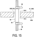
- FIG. 15 is an explanatory diagram illustrating a state in which the cable protection member is supported by bundling bands fastened to cables.
- FIG. 16 (A) is a perspective view of a second protection member section in Modified Example 1, and (B) is a view in the direction of an arrow B in (A).
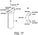
- FIG. 17 (A) is a perspective view of a first protection member section according to Modified Example 1, and (B) is a view in the direction of an arrow B in (A).
- FIG. 18 (A) is a perspective view of a second protection member section according to Modified Example 2, and (B) is a view in the direction of an arrow B in (A).
- FIG. 19 (A) is a perspective view of a first protection member section according to Modified Example 2, and (B) is a view in the direction of an arrow B in (A).
- an aircraft lavatory unit 10 includes a structural frame 12 including a bottom wall 1202, a plurality of wall plates rising from the bottom wall 1202, and a ceiling (not illustrated) that form a lavatory 14 therein.
- one of the plurality of wall plates is a front wall 1204, one is a rear wall 1206 facing the front wall 1204, and the remaining two walls are a pair of side walls 1208 that connect two sides of the rear wall 1206 and corresponding two sides of the front wall 1204, an entrance 1210 opened and closed by a door is provided at the front wall 1204, an inner wall 1212 is provided in front of the rear wall 1206, and a toilet 16 is provided on the bottom wall 1202 via the inner wall 1212.
- one of the pair of side walls 1208, and the door that opens and closes the entrance 1210 are omitted.
- a counter table 18 is provided in the middle of the side wall 1208 in the height direction.
- a lower storage portion 22 in which, for example, a trash can device having a fire extinguishing function (not illustrated) and equipment for the lavatory 14 are stored.
- the lower storage portion 22 is openable and closable by a plurality of doors 2202 and 2204.
- the reference sign 2206 indicates a trash feeding port.
- an upper storage portion 24 in which equipment for the lavatory 14, such as tissues, is stored.
- the upper storage portion 24 is opened and closed by a mirrored door 2402.
- a bowl portion 26 is provided at a section of the counter table 18 close to the front wall 1204, and an automatic faucet 28 that can discharge water to the bowl portion 26 is provided at a section of the counter table 18 around the bowl portion 26.
- the automatic faucet 28 is disposed via a through-hole 30 provided in the counter table 18.
- edges 1810 and 1812 remain around the through-hole 30 and a notch portion 3002 at an upper surface 1802 and a lower surface 1804 of the counter table 18.
- the automatic faucet 28 detects part of a human body (fingers) to discharge and stop water.
- the automatic faucet 28 includes a faucet 32, a contact sensor 34, a non-contact sensor 36, a control unit (not illustrated), and a cable 38.
- the bowl portion 26 is not illustrated in FIGS. 2 and 3 .
- the faucet 32 discharges water supplied from a water supply source (not illustrated) via a water supply path (not illustrated) and hot water supplied from a water heater (not illustrated) provided at the water supply path via a hot water path (not illustrated).
- the faucet 32 is made of various known materials such as metal and synthetic resin.
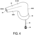
- the faucet 32 includes a base plate portion 40 attached to the upper surface 1802 of the counter table 18, and a faucet body 42 standing from the base plate portion 40 and including a water discharge port 44 at a tip portion thereof.
- the shape of the faucet body 42 is appropriately modified according to a section at which the faucet 32 is installed.
- the faucet body 42 includes a vertical portion 4202 standing upward from the base plate portion 40 and a horizontal portion 4204 extending from the upper part of the vertical portion 4202 toward the bowl portion 26.
- the contact sensor 34 is provided at a front surface 4202A of the horizontal portion 4204 of the faucet body 42 around the water discharge port 44 and detects part of a human body when the part of the human body comes into contact with the contact sensor 34.
- Such a contact sensor 34 can use a known sensor such as a touch switch that detects finger contact or a capacitive touch sensor that detects part of a human body with a change in electrostatic capacitance due to finger contact.
- a touch switch is used as the contact sensor 34.
- the non-contact sensor 36 is provided at a lower surface 4204B of the horizontal portion 4204 of the faucet body 42 around the water discharge port 44 and detects part of a human body in a non-contact manner.
- the lower surface 4204B of the horizontal portion 4204 faces obliquely downward facing the upper side of the bowl portion 26.
- Such a non-contact sensor 36 can use a known sensor such as an infrared sensor that radiates detection light composed of infrared rays to detect part of the human body in response to reflected light or a capacitive non-contact sensor 36 that detects part of a human body in a non-contact manner with a change in electrostatic capacitance due to the approach of the part of the human body.
- the present embodiment uses an infrared sensor as the non-contact sensor 36.
- the base plate portion 40 has an elliptical shape in a plan view.
- an opening 4002 communicating with the interior of the faucet body 42 is provided at the center of a lower surface 4004 of the base plate portion 40, and a pair of connecting pipe portions 46A and 46B connected to the water discharge port 44 is provided on both sides of the opening 4002.
- One connecting pipe portion 46A is a connecting pipe portion for water supply to which the water supply path is connected
- the other connecting pipe portion 46B is a connecting pipe portion for hot water to which the hot water path is connected.
- a rod 48 attached to the faucet body 42 is suspended from the center of the opening 4002, and a male thread 4802 is formed at the lower portion of the rod 48.
- a packing 50 for preventing water leakage having an elliptical annular plate shape is disposed surrounding the pair of connecting pipe portions 46A and 46B and the rod 48.
- the base plate portion 40 of the faucet 32 is attached to the upper surface 1802 of the counter table 18 via the rod 48, a clamp fitting 52 having an elongated shape and a nut N engaged with the male thread 4802.
- the base plate portion 40 of the faucet 32 is attached to the counter table 18 as follows.
- the counter table 18 is provided with a through-hole 30 having an elongated shape which is slightly smaller than the contour of the base plate portion 40.
- the lower surface 4004 of the base plate portion 40 is placed on the upper surface 1802 of the counter table 18 around the through-hole 30 with the packing 50 mounted at the lower surface 4004 of the base plate portion 40, and the base plate portion 40 is positioned to make the major axis direction of the base plate portion 40 parallel to the long side direction of the through-hole 30 and coincide the center of the base plate portion 40 with the center of the through-hole 30.
- the tip of the rod 48 projecting downward from the through-hole 30 is inserted into the clamp fitting 52, both ends of the clamp fitting 52 in the longitudinal direction are brought into contact with the edge portions of a pair of long sides of the through-hole 30, the nut N is screwed onto the male thread 4802 of the rod 48 to tighten the clamp fitting 52 by the nut N, and thus the counter table 18 is sandwiched between the base plate portion 40 and the packing 50, and the clamp fitting 52. This allows the faucet 32 to be attached to the upper surface 1802 of the counter table 18.
- the control unit is provided at a section below the counter table 18 in the vicinity of the automatic faucet 28, and is connected to the contact sensor 34 and the non-contact sensor 36 via the cable 38.
- the control unit switches between water discharge and water stop from the water discharge port 44 based on detection signals output from the contact sensor 34 and the non-contact sensor 36.
- a solenoid valve (not illustrated) is provided at each of the water supply path that supplies water to the faucet 32 and the hot water path that supplies hot water to the faucet 32.
- the control unit Upon receiving a detection signal indicating that the contact sensor 34 or the non-contact sensor 36 has detected part of a human body, the control unit opens the solenoid valve for a predetermined valve opening time to discharge water or hot water from the water discharge port 44, and closes the solenoid valve upon elapse of the valve opening time.
- a selector switch (not illustrated) is connected to the control unit, and the control unit selects whether to supply water or hot water to the faucet 32 based on the operation of the selector switch to operate the electromagnetic valve.
- the cable 38 connects the contact sensor 34 and the non-contact sensor 36 to the control unit. As illustrated in FIGS. 2 to 5 , the cable 38 is drawn from the inside of the faucet body 42 to below the counter table 18 through the opening 4002 and the through-hole 30.
- the cable 38 includes a plurality of electric wires connected to the contact sensor 34 and a plurality of electric wires connected to the non-contact sensor 36.
- the other ends of the plurality of electric wires are coupled to a single connector 54 and are detachably connected to the control unit via the connector 54.
- the connector 54 connected to the cable 38 has an outer diameter larger than the inner diameter of a cable insertion hole 58 to be described below.
- a connector having an outer diameter larger than the inner diameter of the cable insertion hole 58 may be connected to each electric wire.
- Each electric wire includes a core wire that is made of a conductor and transmits a signal, and a covering (core wire covering) that is made of an insulator and covers the core wire.
- FIGS. 2 to 5 illustrate a case in which the cable 38 is a single cable 38 including a plurality of electric wires and a sheath (exterior covering) that is made of an insulator and collectively covers the plurality of electric wires.
- the number of cables 38 is appropriately changed in accordance with the number of sensors provided at the automatic faucet 28.
- FIGS. 6 and 8 illustrate a case in which two cables 38 are used
- FIGS. 7 and 15 illustrate a case in which three cables 38 are used.
- the cable 38 including a plurality of electric wires any cables 38 having various known configurations can be used.
- the cable 38 extends downward from the vicinity of the connecting pipe portion 46A for water supply at the lower surface 4004 of the base plate portion 40 through the notch portion 3002 having an arcuate shape provided at a section closer to one side in the longitudinal direction of one long side of the through-hole 30 of the counter table 18.
- the cable protection member 56 is disposed in the through-hole 30 and the notch portion 3002 to protect the cable 38 from the edges 1810 and 1812.
- the cable protection member 56 includes the cable insertion hole 58 through which the cable 38 is inserted, and is comprised of a pair of protection member sections 56A and 56B which can be divided into a first protection member section 56A and a second protection member section 56B having an elongated shape in a diameter direction of the cable insertion hole 58.
- the pair of protection member sections 56A and 56B includes diameter-direction coupling portions 63 to be immovably coupled in a direction away from each other in the diameter direction of the cable insertion hole 58 and forms therein the cable insertion hole 58 with the pair of protection member sections 56A and 56B coupled via the diameter-direction coupling portions 63.
- the cable protection member 56 includes a cylindrical portion 60 that includes the cable insertion hole 58 and has a uniform outer diameter, and a flange portion 62 which is provided at an end portion of the cylindrical portion 60 in the longitudinal direction, which has an outer diameter larger than the outer diameter of the cylindrical portion 60, and through which the cable insertion hole 58 extends.
- the pair of protection member sections 56A and 56B respectively include cylindrical half-body portions 60A and 60B that form the cylindrical portion 60 in a state of being coupled via the diameter-direction coupling portions 63, and flange half-body portions 62A and 62B which are provided at end portions of the cylindrical half-body portions 60A and 60B in the longitudinal direction and which form the flange portion 62 in a state of being coupled to each other.
- the first protection member section 56A and the second protection member section 56B constituting the cable protection member 56 are made of an insulating synthetic resin.
- the cylindrical half-body portion 60A of the first protection member section 56A is formed in an elongated shape having a semicircular arc cross-section, and the inner circumferential surface thereof constitutes a half portion of the cable insertion hole 58.
- the diameter-direction coupling portion 63 includes a locking groove 64 provided at one of the first protection member section 56A and the second protection member section 56B and a locking projection 66 which is provided at the other of the first protection member section 56A and the second protection member section 56B and can be locked with the locking groove 64.
- the locking groove 64 is provided on both sides of the cylindrical half-body portion 60A in the circumferential direction and extends over substantially the entire length of the cylindrical half-body portion 60A in the longitudinal direction.
- the locking groove 64 includes a circumferential groove 6402 extending in the circumferential direction of the cylindrical half-body portion 60A and a radial groove 6404 extending from an end portion of the circumferential groove 6402 toward an inner side in the radial direction of the cylindrical half-body portion 60A.
- the flange half-body portion 62A of the first protection member section 56A has a semi-annular plate-like shape in a plan view.
- the inner circumferential surface of the flange half-body portion 62A is continuous with the inner circumferential surface of the cylindrical half-body portion 60A.
- the flange half-body portion 62A includes a central portion 6202 located at the center in the extension direction of the flange half-body portion 62A and a pair of side portions 6204 which is provided on both sides of the central portion 6202 and is thinner than the central portion 6202.
- the locking grooves 64 are formed extending from the cylindrical half-body portion 60A to the pair of side portions 6204.
- the cylindrical half-body portion 60B of the second protection member section 56B is formed in an elongated shape having a semicircular arc cross-section, and the inner circumferential surface thereof constitutes a half portion of the cable insertion hole 58.
- the locking projection 66 is provided on both sides of the cylindrical half-body portion 60B in the circumferential direction and extends over substantially the entire length of the cylindrical half-body portion 60B in the longitudinal direction.
- the locking projection 66 includes a circumferential projection 6602 that can be locked with the circumferential groove 6402 and a radial projection 6604 that extends from an end portion of the circumferential projection 6602 toward an inner side in the radial direction of the cylindrical half-body portion 60B and can be locked with the radial groove 6404.
- the shape of the flange half-body portion 62B of the second protection member section 56B includes a semi-annular plate-like portion 6210 and a pair of projection portions 6212 projecting from both sides of the semi-annular plate-like portion 6210 in the circumferential direction in a plan view, and an open portion 6214 is formed between the pair of projection portions 6212.
- the inner circumferential surface of the flange half-body portion 62B is continuous with the inner circumferential surface of the cylindrical half-body portion 60B.
- the pair of projection portions 6212 is formed to have a thickness thinner than the thickness of the semi-annular plate-like portion 6210.
- the pair of locking projections 66 extends from the cylindrical half-body portion 60B to immediately below the pair of projection portions 6212.
- the cable 38 pulled out from the faucet 32 placed on the counter table 18 is covered with the cable protection member 56.
- the first protection member section 56A is positioned with the cable 38 positioned at the inner circumferential surface of the first protection member section 56A covering the half of the cable 38 in the radial direction, an end portion of the cylindrical half-body portion 60B located opposite to the flange half-body portion 62B of the second protection member section 56B is made to face an end portion of the flange half-body portion 62A of the first protection member section 56A, and the first and second protection member sections 56A and 56B are moved in directions approaching each other along the longitudinal direction of the first and second protection member sections 56A and 56B.
- the central portion 6202 of the flange half-body portion 62A of the first protection member section 56A is aligned with the open portion 6214 of the flange half-body portion 62B of the second protection member section 56B
- the projection portions 6212 of the flange half-body portion 62B of the second protection member section 56B are aligned with the pair of side portions 6204 of the flange half-body portion 62A of the first protection member section 56A
- the cable 38 is covered with the cable protection member 56.
- the cable 38 is covered with the cylindrical half-body portions 60A and 60B and the flange half-body portions 62A and 62B of the pair of protection member sections 56A and 56B, whereby a state in which the cable 38 is inserted through the cable insertion hole 58 of the cable protection member 56 is achieved.
- the first and second protection member sections 56A and 56B are moved in directions away from each other along the longitudinal direction of the first and second protection member sections 56A and 56B to separate the end portion of the flange half-body portion 62A of the first protection member section 56A from the end portion of the cylindrical half-body portion 60B located opposite to the flange half-body portion 62B of the second protection member section 56B, the first and second protection member sections 56A and 56B can be divided in the diameter direction of the cable insertion hole 58.
- the upper surface of the first protection member section 56A and the upper surface of the second protection member section 56B are located on the same plane, and the lower surface of the first protection member section 56A and the lower surface of the second protection member section 56B are located on the same plane as illustrated in FIG. 10 .
- the first protection member section 56A and the second protection member section 56B are immovably coupled to each other in the diameter direction of the cable insertion hole 58 by the locking grooves 64 and the locking projections 66 constituting the diameter-direction coupling portions 63, more specifically, by locking between the circumferential grooves 6402 and the circumferential projections 6602 and locking between the radial grooves 6404 and the radial projections 6604.
- the movement of the first protection member section 56A toward the flange half-body portion 62B is restricted by the pair of side portions 6204 of the first protection member section 56A being in contact with the pair of projection portions 6212 of the second protection member section 56B.
- the pair of side portions 6204 and the pair of projection portions 6212 constitute first longitudinal coupling portions 6213 which are immovably coupled to each other in one of both longitudinal directions of the protection member sections 56A and 56B with the pair of protection member sections 56A and 56B coupled to each other.
- the base plate portion 40 of the faucet 32 is moved downward from above the through-hole 30 of the counter table 18 such that the base plate portion 40 is positioned on the upper surface 1802 of the counter table 18 while the rod 48 and the cable 38 are inserted through the through-hole 30.
- the cylindrical portion 60 of the cable protection member 56 is inserted into the notch portion 3002 of the through-hole 30, the flange portion 62 is positioned on the upper surface 1802 of the counter table 18 around the notch portion 3002, and as illustrated in FIG. 7 , the flange portion 62 is pressed against the upper surface 1802 of the counter table 18 by the lower surface 4004 of the base plate portion 40 of the faucet 32.
- a recess portion 4010 having a shape matching the outer shape of the flange portion 62 is formed in the lower surface 4004 of the base plate portion 40, and the flange portion 62 is pressed against the upper surface 1802 of the counter table 18 via the packing 50 by the recess portion 4010 with the flange portion 62 accommodated in the recess portion 4010.
- the cylindrical portion 60 of the cable protection member 56 extends from the inside of the through-hole 30 to below the lower surface 1804 of the counter table 18,
- the flange portion 62 is pressed against the upper surface 1802 of the counter table 18 by the faucet 32, whereby the cable protection member 56 is attached to the counter table 18.
- the cable protection member 56 includes the cable insertion hole 58 through which the cable 38 is inserted and the pair of protection member sections 56A and 56B which can be divided in the diameter direction of the cable insertion hole 58, and the pair of protection member sections 56A and 56B includes the diameter-direction coupling portions 63 to be immovably coupled in a direction away from each other in the diameter direction of the cable insertion hole 58 and forms therein the cable insertion hole 58 with the pair of protection member sections 56A and 56B coupled via the diameter-direction coupling portions 63.
- the cable 38 can be inserted through the cable insertion hole 58 and covered with the cable protection member 56 by coupling the pair of protection member sections 56A and 56B with the cable 38 sandwiched therebetween with the diameter-direction coupling portions 63.
- the cable protection member 56 includes the cylindrical portion 60 having a uniform outer diameter and including the cable insertion hole 58, and the pair of protection member sections 56A and 56B includes the cylindrical half-body portions 60A and 60B which include the diameter-direction coupling portions 63 and form the cylindrical portion 60 in a state of being coupled to each other.
- the cable 38 can be disposed in the through-hole 30 with the cable 38 inserted through the cylindrical portion 60, which is advantageous in protecting the cable 38 from the edges 1810 and 1812 of the wall portion.
- the diameter-direction coupling portions 63 extend over substantially the entire length of the cylindrical portion 60, the diameter-direction coupling portions 63 are unlikely to come off in the diameter direction of the cable insertion hole 58, which is advantageous in reliably covering and protecting the cable 38.
- the flange portion 62 may be omitted and, for example, bundling bands 68 may be used as a movement blocking member that blocks the movement of the cable protection member 56 along the cable 38 as illustrated in FIG. 15 .
- the bundling band 68 may be fastened to portions of the cable 38 projecting from both ends of the cylindrical portion 60 in the longitudinal direction to prevent the cylindrical portion 60 (the cable protection member 56) from moving along the longitudinal direction of the cable 38.
- the cable insertion hole 58 is formed to have an inner diameter larger than the outer diameter of the cable 38 .
- the cable insertion hole 58 may be formed to have an inner diameter that can prevent the movement of the cable 38.
- the diameter-direction coupling portion 63 includes the locking groove 64 provided at the cylindrical half-body portion 60A of one of the pair of protection member sections 56A and 56B and the locking projection 66 which is provided at the cylindrical half-body portion 60B of the other protection member section 56B of the pair of protection member sections 56A and 56B and can be locked with the locking groove 64, which is advantageous in easily forming the diameter-direction coupling portion 63.
- the locking groove 64 includes the circumferential groove 6402 extending in the circumferential direction of the cylindrical half-body portion 60A and the radial groove 6404 extending from the end portion of the circumferential groove 6402 toward the inner side in the radial direction of the cylindrical half-body portion 60A
- the locking projection 66 includes the circumferential projection 6602 that can be locked with the circumferential groove 6402 and the radial projection 6604 that can be locked with the radial groove 6404.
- the cable protection member 56 includes the flange portion 62 which is provided at the end portion of the cylindrical portion 60 in the longitudinal direction and has an outer diameter larger than the outer diameter of the cylindrical portion 60 and through which the cable insertion hole 58 extends, and the pair of protection member sections 56A and 56B includes the flange half-body portions 62A and 62B which are provided at the end portions of the cylindrical half-body portions 60A and 60B in the longitudinal direction and form the flange portion 62 in a state of being coupled to each other.
- the flange portion 62 may be omitted, but in the case of providing the flange portion 62, attaching the flange portion 62 to an upper surface of a wall portion such as the counter table 18 is advantageous in easily disposing the cable protection member 56.
- the flange half-body portions 62A and 62B of the pair of protection member sections 56A and 56B are provided with the first longitudinal coupling portions 6213 which are immovably coupled to each other in one direction of both directions of the longitudinal direction of the protection member sections 56A and 56B with the pair of protection member sections 56A and 56B coupled to each other.
- the pair of protection member sections 56A and 56B includes second longitudinal coupling portions 6260 which are immovably coupled to each other in both directions of the longitudinal direction of the protection member sections 56A and 56B in a state of being coupled to each other, and the second longitudinal coupling portions 6260 are provided at the flange half-body portions 62A and 62B.
- locking recess portions 6220 are provided on end surfaces of both ends of the semi-annular plate-like portion 6210 of the flange half-body portion 62B of the second protection member section 56B as illustrated in FIG. 16
- locking projections 6230 which can be locked with the locking recess portions 6220 are provided at end surfaces of the pair of side portions 6204 of the flange half-body portion 62A of the first protection member section 56A as illustrated in FIG. 17
- the locking recess portions 6220 and the locking projections 6230 constitute the second longitudinal coupling portions 6260.
- the first protection member section 56A is positioned with the cable 38 positioned at the inner circumferential surface of the first protection member section 56A so as to cover the half of the cable 38 in the radial direction, an end portion of the cylindrical half-body portion 60B located opposite to the flange half-body portion 62B of the second protection member section 56B is made to face an end portion of the flange half-body portion 62A of the first protection member section 56A, the first and second protection member sections 56A and 56B are moved in directions approaching each other along the longitudinal direction of the first and second protection member sections 56A and 56B, whereby the central portion 6202 of the flange half-body portion 62A of the first protection member section 56A is aligned with the open portion 6214 of the flange half-body portion 62B of the second protection member section 56B.
- the projection portions 6212 of the flange half-body portion 62B of the second protection member section 56B are aligned with the pair of side portions 6204 of the flange half-body portion 62A of the first protection member section 56A, and at the same time, the locking projections 6230 are locked with the locking recess portions 6220, whereby the first protection member section 56A and the second protection member section 56B are coupled to each other.
- the pair of protection member sections 56A and 56B includes the second longitudinal coupling portions 6260 which are immovably coupled to each other in both directions of the longitudinal direction of the protection member sections 56A and 56B in a state of being coupled to each other, and the second longitudinal coupling portions 6260 are provided at the cylindrical half-body portions 60A and 60B.
- locking recess portions 6240 are provided at places on end surfaces of the locking projections 66 (the circumferential projections 6602) on both sides in the circumferential direction of the cylindrical half-body portion 60B of the second protection member section 56B, the places being located an opposite side of the flange half-body portion 62B.
- locking projections 6250 which can be locked with the locking recess portions 6240 are provided at sections on bottom surfaces of the locking grooves 64 (the circumferential grooves 6402) on both sides in the circumferential direction of the cylindrical half-body portion 60A of the first protection member section 56A, the places being located on an opposite side of the flange half-body portion 62A.
- the locking recess portions 6240 and the locking projections 6250 constitute the second longitudinal coupling portions 6260.
- the first protection member section 56A is positioned with the cable 38 positioned at the inner circumferential surface of the first protection member section 56A so as to cover the half of the cable 38 in the radial direction, an end portion of the cylindrical half-body portion 60B located opposite to the flange half-body portion 62B of the second protection member section 56B is made to face an end portion of the flange half-body portion 62A of the first protection member section 56A, the first and second protection member sections 56A and 56B are moved in directions approaching each other, whereby the central portion 6202 of the flange half-body portion 62A of the first protection member section 56A is aligned with the open portion 6214 of the flange half-body portion 62B of the second protection member section 56B.
- the projection portions 6212 of the flange half-body portion 62B of the second protection member section 56B are aligned with the pair of side portions 6204 of the flange half-body portion 62A of the first protection member section 56A, and at the same time, the locking projections 6250 are locked with the locking recess portions 6240, whereby the first protection member section 56A and the second protection member section 56B are completely coupled to each other.
- the second longitudinal coupling portions 6260 of Modified Example 2 can be also applied to the cable protection member 56 from which the flange portion 62 is omitted.
Landscapes
- Engineering & Computer Science (AREA)
- Architecture (AREA)
- Structural Engineering (AREA)
- Civil Engineering (AREA)
- Aviation & Aerospace Engineering (AREA)
- Water Supply & Treatment (AREA)
- Health & Medical Sciences (AREA)
- Public Health (AREA)
- Hydrology & Water Resources (AREA)
- Life Sciences & Earth Sciences (AREA)
- Installation Of Indoor Wiring (AREA)
- Toilet Supplies (AREA)
- Bathtubs, Showers, And Their Attachments (AREA)
- Protection Of Pipes Against Damage, Friction, And Corrosion (AREA)
- Supports For Pipes And Cables (AREA)
Abstract
Description
- The present invention relates to a cable protection member and an aircraft lavatory unit equipped with the cable protection member.
- In wiring a cable that connects electrical devices installed on-site, a tube-shaped cable protection member that covers and protects the cable not to damage the cable by touching a surrounding structure around which the cable is routed has been proposed (see Patent Document 1).
- Such a cable protection member covers the cable, with the cable inserted into the inside of the cable protection member.
- Patent Document 1:
JP 2016-86600 A - In protecting a cable having one end connected to an electrical device and the other end attached with a connector by using the cable protection member described above, the outer diameter of the connector is larger than the inner diameter of the cable protection member in many cases, thus failing to insert the cable into the cable protection member due to obstruction of the connector.
- Thus, in such a case, it is necessary to once detach the connector from the cable and insert the cable into the cable protection member and then reattach the connector to a portion of the cable exposed from an end portion of the cable protection member. That is, detachment and attachment work of the connector is needed, which is disadvantageous in efficient cable protection work on-site.
- In a lavatory unit for aircraft, for example, a faucet installed on the upper surface of a counter table of a lavatory and equipped with a sensor detecting part of a human body and a control unit which is installed below the counter table and controls water discharge and water stop of the faucet in response to a detection signal of the sensor may be connected by a cable having one end of the cable connected to the faucet side and the other end of the cable attached to a connector.
- In protecting the cable with the above-described cable protection member, the outer diameter of the connector is larger than the inner diameter of the cable protection member as described above. This needs detachment and attachment work of the connector and is disadvantageous in efficient cable protection work on-site.
- Meanwhile, in a lavatory unit for aircraft, a faucet is attached via a through-hole formed in a counter table, and a cable is connected to a control unit located below the counter table through the through-hole.
- A section around the through-hole at the lower surface of the counter table is an edge, and the cable is disposed passing near the edge.
- Thus, severe vibration of a fuselage when an aircraft enters an air pocket during flight may cause the cable to contact the edge and damage a covered portion of the cable. When the covered portion is damaged, maintenance work at the time of maintenance, such as replacement of the cable, becomes troublesome, and thus any improvement has been awaited.
- The present invention has been made in view of the above circumstances, and an object of the present invention is to provide a cable protection member that is advantageous in improving efficiency of cable protection work and an aircraft lavatory unit including the cable protection member that is advantageous in improving efficiency of protection work of a cable to be used in the aircraft lavatory unit and in protecting the cable.
- To achieve the above object, an embodiment of the present invention is a cable protection member for protecting a cable. The cable protection member includes a cable insertion hole through which the cable is inserted and a pair of protection member sections divisible in a diameter direction of the cable insertion hole. The pair of protection member sections include diameter-direction coupling portions to be immovably coupled in a direction away from each other in the diameter direction of the cable insertion hole, and the cable insertion hole is formed inside the pair of protection member sections that are being coupled via the diameter-direction coupling portions.
- According to the embodiment of the present invention, without detaching the connector from the cable, the cable can be inserted through the cable insertion hole and covered with the cable protection member by coupling the pair of protection member sections with the cable sandwiched therebetween with the diameter-direction coupling portions, allowing the cable to be easily and reliably covered and protected by the cable protection member. This is advantageous in improving efficiency of cable protection work and in simplifying maintenance work.
-
-
FIG. 1 is a perspective view of an aircraft lavatory unit to which a cable protection member according to an embodiment is applied. -
FIG. 2 is an enlarged perspective view of a portion of a counter table to which an automatic faucet is attached. -
FIG. 3 is a bottom view ofFIG. 2 as viewed from below the counter table, illustrating a state in which the cable protection member according to the embodiment is installed at a cable. -
FIG. 4 is a perspective view of the automatic faucet as viewed obliquely from above. -
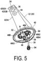
FIG. 5 is a perspective view of the automatic faucet as viewed obliquely from below, illustrating a state in which the cable protection member according to the embodiment is provided at the cable of the automatic faucet. -
FIGS. 6 (A), (B), and (C) are explanatory diagrams illustrating a state in which the cable protection member according to the embodiment is installed at a notch portion of the counter table. -
FIG. 7 is a cross-sectional view illustrating a state in which the cable protection member according to the embodiment is installed at the notch portion of the counter table. -
FIGS. 8 (A), (B), and (C) are explanatory diagrams illustrating a procedure for assembling the cable protection member according to the embodiment. -
FIG. 9 illustrates assembly diagrams of the cable protection member according to the embodiment, wherein (A) is a perspective view, (B) is a view in the direction of an arrow B in (A), and (C) is a view in the direction of an arrow C in (A). -
FIG. 10 illustrates assembly diagrams of the cable protection member according to the embodiment, wherein (A) is a front view, (B) is a view in the direction of an arrow B in (A), and (C) is a view in the direction of an arrow C in (A). - In
FIG. 11, (A) is a perspective view of a first protection member section, (B) is a view in the direction of an arrow B in (A), and (C) is a view in the direction of an arrow C in (A). - In
FIG. 12, (A) is a front view of the first protection member section, (B) is a view in the direction of an arrow B in (A), and (C) is a view in the direction of an arrow C in (A). - In
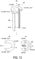
FIG. 13, (A) is a perspective view of a second protection member section, (B) is a view in the direction of an arrow B in (A), and (C) is a view in the direction of an arrow C in (A). - In
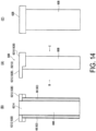
FIG. 14, (A) is a front view of the second protection member section, (B) is a view in the direction of an arrow B in (A), and (C) is a view in the direction of an arrow C in (A). -
FIG. 15 is an explanatory diagram illustrating a state in which the cable protection member is supported by bundling bands fastened to cables. - In
FIG. 16, (A) is a perspective view of a second protection member section in Modified Example 1, and (B) is a view in the direction of an arrow B in (A). - In
FIG. 17, (A) is a perspective view of a first protection member section according to Modified Example 1, and (B) is a view in the direction of an arrow B in (A). - In
FIG. 18, (A) is a perspective view of a second protection member section according to Modified Example 2, and (B) is a view in the direction of an arrow B in (A). - In
FIG. 19, (A) is a perspective view of a first protection member section according to Modified Example 2, and (B) is a view in the direction of an arrow B in (A). - Next, the present embodiment will be described with reference to the drawings.
- In the present embodiment, a case in which a cable protection member according to an embodiment of the present invention is applied to an automatic faucet constituting a counter table device of an aircraft lavatory unit will be described.
- First, an aircraft lavatory unit will be described.
- As illustrated in
FIG. 1 , anaircraft lavatory unit 10 includes astructural frame 12 including abottom wall 1202, a plurality of wall plates rising from thebottom wall 1202, and a ceiling (not illustrated) that form alavatory 14 therein. - In the present embodiment, one of the plurality of wall plates is a
front wall 1204, one is arear wall 1206 facing thefront wall 1204, and the remaining two walls are a pair ofside walls 1208 that connect two sides of therear wall 1206 and corresponding two sides of thefront wall 1204, anentrance 1210 opened and closed by a door is provided at thefront wall 1204, aninner wall 1212 is provided in front of therear wall 1206, and atoilet 16 is provided on thebottom wall 1202 via theinner wall 1212. - In
FIG. 1 , one of the pair ofside walls 1208, and the door that opens and closes theentrance 1210 are omitted. - A counter table 18 is provided in the middle of the
side wall 1208 in the height direction. Below the counter table 18 is alower storage portion 22 in which, for example, a trash can device having a fire extinguishing function (not illustrated) and equipment for thelavatory 14 are stored. Thelower storage portion 22 is openable and closable by a plurality ofdoors FIG. 1 , thereference sign 2206 indicates a trash feeding port. - Above the counter table 18 is an upper storage portion 24 in which equipment for the
lavatory 14, such as tissues, is stored. The upper storage portion 24 is opened and closed by a mirrored door 2402. - A
bowl portion 26 is provided at a section of the counter table 18 close to thefront wall 1204, and anautomatic faucet 28 that can discharge water to thebowl portion 26 is provided at a section of the counter table 18 around thebowl portion 26. - As illustrated in
FIG. 3 , theautomatic faucet 28 is disposed via a through-hole 30 provided in the counter table 18. - As illustrated in
FIG. 6(A) ,edges hole 30 and anotch portion 3002 at anupper surface 1802 and alower surface 1804 of the counter table 18. - The
automatic faucet 28 detects part of a human body (fingers) to discharge and stop water. - As illustrated in
FIGS. 2 to 5 , theautomatic faucet 28 includes afaucet 32, acontact sensor 34, anon-contact sensor 36, a control unit (not illustrated), and acable 38. - The
bowl portion 26 is not illustrated inFIGS. 2 and3 . - The
faucet 32 discharges water supplied from a water supply source (not illustrated) via a water supply path (not illustrated) and hot water supplied from a water heater (not illustrated) provided at the water supply path via a hot water path (not illustrated). - The
faucet 32 is made of various known materials such as metal and synthetic resin. - As illustrated in
FIGS. 2 to 5 , thefaucet 32 includes abase plate portion 40 attached to theupper surface 1802 of the counter table 18, and afaucet body 42 standing from thebase plate portion 40 and including awater discharge port 44 at a tip portion thereof. - The shape of the
faucet body 42 is appropriately modified according to a section at which thefaucet 32 is installed. In the present embodiment, as illustrated inFIGS. 2 and4 , thefaucet body 42 includes avertical portion 4202 standing upward from thebase plate portion 40 and ahorizontal portion 4204 extending from the upper part of thevertical portion 4202 toward thebowl portion 26. - As illustrated in
FIGS. 4 and5 , thecontact sensor 34 is provided at afront surface 4202A of thehorizontal portion 4204 of thefaucet body 42 around thewater discharge port 44 and detects part of a human body when the part of the human body comes into contact with thecontact sensor 34. - Such a
contact sensor 34 can use a known sensor such as a touch switch that detects finger contact or a capacitive touch sensor that detects part of a human body with a change in electrostatic capacitance due to finger contact. In the present embodiment, a touch switch is used as thecontact sensor 34. - As illustrated in
FIG. 5 , thenon-contact sensor 36 is provided at a lower surface 4204B of thehorizontal portion 4204 of thefaucet body 42 around thewater discharge port 44 and detects part of a human body in a non-contact manner. - The lower surface 4204B of the
horizontal portion 4204 faces obliquely downward facing the upper side of thebowl portion 26. - Such a
non-contact sensor 36 can use a known sensor such as an infrared sensor that radiates detection light composed of infrared rays to detect part of the human body in response to reflected light or a capacitivenon-contact sensor 36 that detects part of a human body in a non-contact manner with a change in electrostatic capacitance due to the approach of the part of the human body. The present embodiment uses an infrared sensor as thenon-contact sensor 36. - As illustrated in
FIGS. 4 and5 , thebase plate portion 40 has an elliptical shape in a plan view. - As illustrated in
FIG. 5 , anopening 4002 communicating with the interior of thefaucet body 42 is provided at the center of alower surface 4004 of thebase plate portion 40, and a pair of connectingpipe portions water discharge port 44 is provided on both sides of theopening 4002. - One connecting
pipe portion 46A is a connecting pipe portion for water supply to which the water supply path is connected, and the other connectingpipe portion 46B is a connecting pipe portion for hot water to which the hot water path is connected. - A
rod 48 attached to thefaucet body 42 is suspended from the center of theopening 4002, and amale thread 4802 is formed at the lower portion of therod 48. - At the
lower surface 4004 of thebase plate portion 40 located around theopening 4002, a packing 50 for preventing water leakage having an elliptical annular plate shape is disposed surrounding the pair of connectingpipe portions rod 48. - As illustrated in
FIG. 3 , thebase plate portion 40 of thefaucet 32 is attached to theupper surface 1802 of the counter table 18 via therod 48, a clamp fitting 52 having an elongated shape and a nut N engaged with themale thread 4802. - The
base plate portion 40 of thefaucet 32 is attached to the counter table 18 as follows. - The counter table 18 is provided with a through-
hole 30 having an elongated shape which is slightly smaller than the contour of thebase plate portion 40. - The
lower surface 4004 of thebase plate portion 40 is placed on theupper surface 1802 of the counter table 18 around the through-hole 30 with the packing 50 mounted at thelower surface 4004 of thebase plate portion 40, and thebase plate portion 40 is positioned to make the major axis direction of thebase plate portion 40 parallel to the long side direction of the through-hole 30 and coincide the center of thebase plate portion 40 with the center of the through-hole 30. - Next, the tip of the
rod 48 projecting downward from the through-hole 30 is inserted into the clamp fitting 52, both ends of the clamp fitting 52 in the longitudinal direction are brought into contact with the edge portions of a pair of long sides of the through-hole 30, the nut N is screwed onto themale thread 4802 of therod 48 to tighten the clamp fitting 52 by the nut N, and thus the counter table 18 is sandwiched between thebase plate portion 40 and the packing 50, and the clamp fitting 52. This allows thefaucet 32 to be attached to theupper surface 1802 of the counter table 18. - The control unit is provided at a section below the counter table 18 in the vicinity of the
automatic faucet 28, and is connected to thecontact sensor 34 and thenon-contact sensor 36 via thecable 38. - The control unit switches between water discharge and water stop from the
water discharge port 44 based on detection signals output from thecontact sensor 34 and thenon-contact sensor 36. - In the present embodiment, a solenoid valve (not illustrated) is provided at each of the water supply path that supplies water to the
faucet 32 and the hot water path that supplies hot water to thefaucet 32. Upon receiving a detection signal indicating that thecontact sensor 34 or thenon-contact sensor 36 has detected part of a human body, the control unit opens the solenoid valve for a predetermined valve opening time to discharge water or hot water from thewater discharge port 44, and closes the solenoid valve upon elapse of the valve opening time. - In this way, a predetermined amount of water or hot water is discharged from the
faucet 32 by opening the valve for a certain valve opening time. - A selector switch (not illustrated) is connected to the control unit, and the control unit selects whether to supply water or hot water to the
faucet 32 based on the operation of the selector switch to operate the electromagnetic valve. - The
cable 38 connects thecontact sensor 34 and thenon-contact sensor 36 to the control unit. As illustrated inFIGS. 2 to 5 , thecable 38 is drawn from the inside of thefaucet body 42 to below the counter table 18 through theopening 4002 and the through-hole 30. - The
cable 38 includes a plurality of electric wires connected to thecontact sensor 34 and a plurality of electric wires connected to thenon-contact sensor 36. The other ends of the plurality of electric wires are coupled to asingle connector 54 and are detachably connected to the control unit via theconnector 54. - In the present embodiment, the
connector 54 connected to thecable 38 has an outer diameter larger than the inner diameter of acable insertion hole 58 to be described below. - Instead of providing the
single connector 54, a connector having an outer diameter larger than the inner diameter of thecable insertion hole 58 may be connected to each electric wire. - Each electric wire includes a core wire that is made of a conductor and transmits a signal, and a covering (core wire covering) that is made of an insulator and covers the core wire.
-
FIGS. 2 to 5 illustrate a case in which thecable 38 is asingle cable 38 including a plurality of electric wires and a sheath (exterior covering) that is made of an insulator and collectively covers the plurality of electric wires. - The number of
cables 38 is appropriately changed in accordance with the number of sensors provided at theautomatic faucet 28.FIGS. 6 and8 illustrate a case in which twocables 38 are used, andFIGS. 7 and15 illustrate a case in which threecables 38 are used. As thecable 38 including a plurality of electric wires, anycables 38 having various known configurations can be used. - As illustrated in
FIGS. 3 ,6 , and7 , thecable 38 extends downward from the vicinity of the connectingpipe portion 46A for water supply at thelower surface 4004 of thebase plate portion 40 through thenotch portion 3002 having an arcuate shape provided at a section closer to one side in the longitudinal direction of one long side of the through-hole 30 of the counter table 18. - The
cable protection member 56 according to the present embodiment is disposed in the through-hole 30 and thenotch portion 3002 to protect thecable 38 from theedges - As illustrated in
FIGS. 8 and9 , thecable protection member 56 includes thecable insertion hole 58 through which thecable 38 is inserted, and is comprised of a pair ofprotection member sections protection member section 56A and a secondprotection member section 56B having an elongated shape in a diameter direction of thecable insertion hole 58. - The pair of
protection member sections direction coupling portions 63 to be immovably coupled in a direction away from each other in the diameter direction of thecable insertion hole 58 and forms therein thecable insertion hole 58 with the pair ofprotection member sections direction coupling portions 63. - As illustrated in
FIG. 9 , in the present embodiment, thecable protection member 56 includes acylindrical portion 60 that includes thecable insertion hole 58 and has a uniform outer diameter, and aflange portion 62 which is provided at an end portion of thecylindrical portion 60 in the longitudinal direction, which has an outer diameter larger than the outer diameter of thecylindrical portion 60, and through which thecable insertion hole 58 extends. - The pair of
protection member sections body portions cylindrical portion 60 in a state of being coupled via the diameter-direction coupling portions 63, and flange half-body portions body portions flange portion 62 in a state of being coupled to each other. - The first
protection member section 56A and the secondprotection member section 56B constituting thecable protection member 56 are made of an insulating synthetic resin. - As illustrated in
FIGS. 11 and12 , the cylindrical half-body portion 60A of the firstprotection member section 56A is formed in an elongated shape having a semicircular arc cross-section, and the inner circumferential surface thereof constitutes a half portion of thecable insertion hole 58. - As illustrated in
FIG. 9(C) , the diameter-direction coupling portion 63 includes a lockinggroove 64 provided at one of the firstprotection member section 56A and the secondprotection member section 56B and a lockingprojection 66 which is provided at the other of the firstprotection member section 56A and the secondprotection member section 56B and can be locked with the lockinggroove 64. - As illustrated in
FIGS. 11 and12 , in the present embodiment, the lockinggroove 64 is provided on both sides of the cylindrical half-body portion 60A in the circumferential direction and extends over substantially the entire length of the cylindrical half-body portion 60A in the longitudinal direction. - As illustrated in
FIGS. 11(B) and 11(C) , the lockinggroove 64 includes acircumferential groove 6402 extending in the circumferential direction of the cylindrical half-body portion 60A and aradial groove 6404 extending from an end portion of thecircumferential groove 6402 toward an inner side in the radial direction of the cylindrical half-body portion 60A. - As illustrated in
FIG. 11(B) , the flange half-body portion 62A of the firstprotection member section 56A has a semi-annular plate-like shape in a plan view. - The inner circumferential surface of the flange half-
body portion 62A is continuous with the inner circumferential surface of the cylindrical half-body portion 60A. - As illustrated in
FIGS. 11(A), 11(B) and12(B) , the flange half-body portion 62A includes acentral portion 6202 located at the center in the extension direction of the flange half-body portion 62A and a pair ofside portions 6204 which is provided on both sides of thecentral portion 6202 and is thinner than thecentral portion 6202. - The locking
grooves 64 are formed extending from the cylindrical half-body portion 60A to the pair ofside portions 6204. - As illustrated in
FIGS. 13 and14 , the cylindrical half-body portion 60B of the secondprotection member section 56B is formed in an elongated shape having a semicircular arc cross-section, and the inner circumferential surface thereof constitutes a half portion of thecable insertion hole 58. - In the present embodiment, the locking
projection 66 is provided on both sides of the cylindrical half-body portion 60B in the circumferential direction and extends over substantially the entire length of the cylindrical half-body portion 60B in the longitudinal direction. - As illustrated in
FIG. 13(C) , the lockingprojection 66 includes acircumferential projection 6602 that can be locked with thecircumferential groove 6402 and aradial projection 6604 that extends from an end portion of thecircumferential projection 6602 toward an inner side in the radial direction of the cylindrical half-body portion 60B and can be locked with theradial groove 6404. - As illustrated in
FIG. 13(B) , the shape of the flange half-body portion 62B of the secondprotection member section 56B includes a semi-annular plate-like portion 6210 and a pair ofprojection portions 6212 projecting from both sides of the semi-annular plate-like portion 6210 in the circumferential direction in a plan view, and anopen portion 6214 is formed between the pair ofprojection portions 6212. - The inner circumferential surface of the flange half-
body portion 62B is continuous with the inner circumferential surface of the cylindrical half-body portion 60B. - As illustrated in
FIG. 14(A) , the pair ofprojection portions 6212 is formed to have a thickness thinner than the thickness of the semi-annular plate-like portion 6210. - As illustrated in
FIG. 14(B) , the pair of lockingprojections 66 extends from the cylindrical half-body portion 60B to immediately below the pair ofprojection portions 6212. - Next, a method of using the
cable protection member 56 will be described. - First, the
cable 38 pulled out from thefaucet 32 placed on the counter table 18 is covered with thecable protection member 56. - More specifically, as illustrated in
FIG. 8(A) , the firstprotection member section 56A is positioned with thecable 38 positioned at the inner circumferential surface of the firstprotection member section 56A covering the half of thecable 38 in the radial direction, an end portion of the cylindrical half-body portion 60B located opposite to the flange half-body portion 62B of the secondprotection member section 56B is made to face an end portion of the flange half-body portion 62A of the firstprotection member section 56A, and the first and secondprotection member sections protection member sections - By this movement, the locking
projections 66 are locked with the lockinggrooves 64 as illustrated inFIG. 8(B) , and the pair ofside portions 6204 of the flange half-body portion 62A of the firstprotection member section 56A comes into contact with the pair ofprojection portions 6212 of the flange half-body portion 62B of the secondprotection member section 56B as illustrated inFIG. 8(C) . - In this state, the
central portion 6202 of the flange half-body portion 62A of the firstprotection member section 56A is aligned with theopen portion 6214 of the flange half-body portion 62B of the secondprotection member section 56B, theprojection portions 6212 of the flange half-body portion 62B of the secondprotection member section 56B are aligned with the pair ofside portions 6204 of the flange half-body portion 62A of the firstprotection member section 56A, and thecable 38 is covered with thecable protection member 56. - That is, the
cable 38 is covered with the cylindrical half-body portions body portions protection member sections cable 38 is inserted through thecable insertion hole 58 of thecable protection member 56 is achieved. - In this state, when the first and second
protection member sections protection member sections body portion 62A of the firstprotection member section 56A from the end portion of the cylindrical half-body portion 60B located opposite to the flange half-body portion 62B of the secondprotection member section 56B, the first and secondprotection member sections cable insertion hole 58. - In this state, the upper surface of the first
protection member section 56A and the upper surface of the secondprotection member section 56B are located on the same plane, and the lower surface of the firstprotection member section 56A and the lower surface of the secondprotection member section 56B are located on the same plane as illustrated inFIG. 10 . - The first
protection member section 56A and the secondprotection member section 56B are immovably coupled to each other in the diameter direction of thecable insertion hole 58 by the lockinggrooves 64 and the lockingprojections 66 constituting the diameter-direction coupling portions 63, more specifically, by locking between thecircumferential grooves 6402 and thecircumferential projections 6602 and locking between theradial grooves 6404 and theradial projections 6604. - As illustrated in
FIGS. 8(C) ,10(A), and 10(B) , the movement of the firstprotection member section 56A toward the flange half-body portion 62B is restricted by the pair ofside portions 6204 of the firstprotection member section 56A being in contact with the pair ofprojection portions 6212 of the secondprotection member section 56B. - Thus, the pair of
side portions 6204 and the pair ofprojection portions 6212 constitute firstlongitudinal coupling portions 6213 which are immovably coupled to each other in one of both longitudinal directions of theprotection member sections protection member sections - Next, as illustrated in
FIGS. 2 and3 , with thecable 38 inserted through thecable protection member 56, thebase plate portion 40 of thefaucet 32 is moved downward from above the through-hole 30 of the counter table 18 such that thebase plate portion 40 is positioned on theupper surface 1802 of the counter table 18 while therod 48 and thecable 38 are inserted through the through-hole 30. - At this time, as illustrated in
FIG. 6(B) , thecylindrical portion 60 of thecable protection member 56 is inserted into thenotch portion 3002 of the through-hole 30, theflange portion 62 is positioned on theupper surface 1802 of the counter table 18 around thenotch portion 3002, and as illustrated inFIG. 7 , theflange portion 62 is pressed against theupper surface 1802 of the counter table 18 by thelower surface 4004 of thebase plate portion 40 of thefaucet 32. - As illustrated in
FIG. 7 , in the present embodiment, arecess portion 4010 having a shape matching the outer shape of theflange portion 62 is formed in thelower surface 4004 of thebase plate portion 40, and theflange portion 62 is pressed against theupper surface 1802 of the counter table 18 via the packing 50 by therecess portion 4010 with theflange portion 62 accommodated in therecess portion 4010. - With the
cable protection member 56 attached to the counter table 18 as described above, thecylindrical portion 60 of thecable protection member 56 extends from the inside of the through-hole 30 to below thelower surface 1804 of the counter table 18, - In this state, as illustrated in
FIG. 3 , by screwing the nut N onto themale thread 4802 of therod 48 to tighten the clamp fitting 52 with the nut N, the counter table 18 is sandwiched between thebase plate portion 40 and the clamp fitting 52 with interposition of the packing 50, whereby thefaucet 32 is attached to theupper surface 1802 of the counter table 18. - As a result, the
flange portion 62 is pressed against theupper surface 1802 of the counter table 18 by thefaucet 32, whereby thecable protection member 56 is attached to the counter table 18. - According to the present embodiment, the
cable protection member 56 includes thecable insertion hole 58 through which thecable 38 is inserted and the pair ofprotection member sections cable insertion hole 58, and the pair ofprotection member sections direction coupling portions 63 to be immovably coupled in a direction away from each other in the diameter direction of thecable insertion hole 58 and forms therein thecable insertion hole 58 with the pair ofprotection member sections direction coupling portions 63. - Thus, even with the
connector 54 having an outer diameter larger than the inner diameter of thecable insertion hole 58 attached to an end portion of thecable 38, without detaching theconnector 54 from thecable 38, thecable 38 can be inserted through thecable insertion hole 58 and covered with thecable protection member 56 by coupling the pair ofprotection member sections cable 38 sandwiched therebetween with the diameter-direction coupling portions 63. - This allows the
cable 38 to be easily and reliably covered and protected by thecable protection member 56 and is advantageous in improving efficiency of protection work of thecable 38. - In the
aircraft lavatory unit 10, even when severe vibration occurs in a fuselage because an aircraft enters an air pocket during flight and thecable 38 is about to come into contact with theedges cable 38 near theedges cylindrical portion 60 of thecable protection member 56, and thus damage to thecable 38 is prevented, which is advantageous in simplifying maintenance work. - In the present embodiment, the
cable protection member 56 includes thecylindrical portion 60 having a uniform outer diameter and including thecable insertion hole 58, and the pair ofprotection member sections body portions direction coupling portions 63 and form thecylindrical portion 60 in a state of being coupled to each other. - Thus, even when the
cable 38 is inserted into the through-hole 30 of a wall portion including the counter table 18, thecable 38 can be disposed in the through-hole 30 with thecable 38 inserted through thecylindrical portion 60, which is advantageous in protecting thecable 38 from theedges - Since the diameter-
direction coupling portions 63 extend over substantially the entire length of thecylindrical portion 60, the diameter-direction coupling portions 63 are unlikely to come off in the diameter direction of thecable insertion hole 58, which is advantageous in reliably covering and protecting thecable 38. - In this case, the
flange portion 62 may be omitted and, for example, bundlingbands 68 may be used as a movement blocking member that blocks the movement of thecable protection member 56 along thecable 38 as illustrated inFIG. 15 . - That is, the bundling
band 68 may be fastened to portions of thecable 38 projecting from both ends of thecylindrical portion 60 in the longitudinal direction to prevent the cylindrical portion 60 (the cable protection member 56) from moving along the longitudinal direction of thecable 38. - In the present embodiment, a case in which the
cable insertion hole 58 is formed to have an inner diameter larger than the outer diameter of thecable 38 has been described. However, thecable insertion hole 58 may be formed to have an inner diameter that can prevent the movement of thecable 38. When thecable protection member 56 is attached to thecable 38 in this manner, it is advantageous in omitting a movement prevention member such as the bundlingbands 68. - In the present embodiment, the diameter-
direction coupling portion 63 includes the lockinggroove 64 provided at the cylindrical half-body portion 60A of one of the pair ofprotection member sections projection 66 which is provided at the cylindrical half-body portion 60B of the otherprotection member section 56B of the pair ofprotection member sections groove 64, which is advantageous in easily forming the diameter-direction coupling portion 63. - In the present embodiment, the locking
groove 64 includes thecircumferential groove 6402 extending in the circumferential direction of the cylindrical half-body portion 60A and theradial groove 6404 extending from the end portion of thecircumferential groove 6402 toward the inner side in the radial direction of the cylindrical half-body portion 60A, and the lockingprojection 66 includes thecircumferential projection 6602 that can be locked with thecircumferential groove 6402 and theradial projection 6604 that can be locked with theradial groove 6404. Thus, it is advantageous in reliably and immovably coupling theprotection member sections cable insertion hole 58 with thecable protection member 56 attached to thecable 38. - In the present embodiment, the
cable protection member 56 includes theflange portion 62 which is provided at the end portion of thecylindrical portion 60 in the longitudinal direction and has an outer diameter larger than the outer diameter of thecylindrical portion 60 and through which thecable insertion hole 58 extends, and the pair ofprotection member sections body portions body portions flange portion 62 in a state of being coupled to each other. - The
flange portion 62 may be omitted, but in the case of providing theflange portion 62, attaching theflange portion 62 to an upper surface of a wall portion such as the counter table 18 is advantageous in easily disposing thecable protection member 56. - In the present embodiment, the flange half-
body portions protection member sections longitudinal coupling portions 6213 which are immovably coupled to each other in one direction of both directions of the longitudinal direction of theprotection member sections protection member sections - Thus, in covering the
cable 38 with thecable protection member 56, it is possible to prevent the pair ofprotection member sections protection member sections protection member sections - Next, Modified Example 1 of the present embodiment will be described with reference to
FIGS. 16 and17 . - In the following description of modified examples, the same sections and members as those in the first embodiment will be denoted by the same reference signs, descriptions thereof will be omitted, and different sections will be mainly described.
- In Modified Example 1, the pair of
protection member sections longitudinal coupling portions 6260 which are immovably coupled to each other in both directions of the longitudinal direction of theprotection member sections longitudinal coupling portions 6260 are provided at the flange half-body portions - That is, locking
recess portions 6220 are provided on end surfaces of both ends of the semi-annular plate-like portion 6210 of the flange half-body portion 62B of the secondprotection member section 56B as illustrated inFIG. 16 , lockingprojections 6230 which can be locked with the lockingrecess portions 6220 are provided at end surfaces of the pair ofside portions 6204 of the flange half-body portion 62A of the firstprotection member section 56A as illustrated inFIG. 17 , and thelocking recess portions 6220 and the lockingprojections 6230 constitute the secondlongitudinal coupling portions 6260. - Accordingly, the first
protection member section 56A is positioned with thecable 38 positioned at the inner circumferential surface of the firstprotection member section 56A so as to cover the half of thecable 38 in the radial direction, an end portion of the cylindrical half-body portion 60B located opposite to the flange half-body portion 62B of the secondprotection member section 56B is made to face an end portion of the flange half-body portion 62A of the firstprotection member section 56A, the first and secondprotection member sections protection member sections central portion 6202 of the flange half-body portion 62A of the firstprotection member section 56A is aligned with theopen portion 6214 of the flange half-body portion 62B of the secondprotection member section 56B. - Then, the
projection portions 6212 of the flange half-body portion 62B of the secondprotection member section 56B are aligned with the pair ofside portions 6204 of the flange half-body portion 62A of the firstprotection member section 56A, and at the same time, the lockingprojections 6230 are locked with the lockingrecess portions 6220, whereby the firstprotection member section 56A and the secondprotection member section 56B are coupled to each other. - This allows the pair of
protection member sections protection member sections cable 38 covered with thecable protection member 56. - Thus, in covering the
cable 38 with thecable protection member 56, it is possible to prevent the pair ofprotection member sections protection member sections protection member sections - Next, Modified Example 2 of the present embodiment will be described with reference to
FIGS. 18 and19 . - In Modified Example 2, the pair of
protection member sections longitudinal coupling portions 6260 which are immovably coupled to each other in both directions of the longitudinal direction of theprotection member sections longitudinal coupling portions 6260 are provided at the cylindrical half-body portions - That is, as illustrated in
FIG. 18 , lockingrecess portions 6240 are provided at places on end surfaces of the locking projections 66 (the circumferential projections 6602) on both sides in the circumferential direction of the cylindrical half-body portion 60B of the secondprotection member section 56B, the places being located an opposite side of the flange half-body portion 62B. As illustrated inFIG. 19 , lockingprojections 6250 which can be locked with the lockingrecess portions 6240 are provided at sections on bottom surfaces of the locking grooves 64 (the circumferential grooves 6402) on both sides in the circumferential direction of the cylindrical half-body portion 60A of the firstprotection member section 56A, the places being located on an opposite side of the flange half-body portion 62A. The lockingrecess portions 6240 and the lockingprojections 6250 constitute the secondlongitudinal coupling portions 6260. - Accordingly, the first
protection member section 56A is positioned with thecable 38 positioned at the inner circumferential surface of the firstprotection member section 56A so as to cover the half of thecable 38 in the radial direction, an end portion of the cylindrical half-body portion 60B located opposite to the flange half-body portion 62B of the secondprotection member section 56B is made to face an end portion of the flange half-body portion 62A of the firstprotection member section 56A, the first and secondprotection member sections central portion 6202 of the flange half-body portion 62A of the firstprotection member section 56A is aligned with theopen portion 6214 of the flange half-body portion 62B of the secondprotection member section 56B. - Then, the
projection portions 6212 of the flange half-body portion 62B of the secondprotection member section 56B are aligned with the pair ofside portions 6204 of the flange half-body portion 62A of the firstprotection member section 56A, and at the same time, the lockingprojections 6250 are locked with the lockingrecess portions 6240, whereby the firstprotection member section 56A and the secondprotection member section 56B are completely coupled to each other. - This allows the pair of
protection member sections protection member sections cable 38 covered with thecable protection member 56. - Thus, in covering the
cable 38 with thecable protection member 56, it is possible to prevent the pair ofprotection member sections protection member sections protection member sections - The second
longitudinal coupling portions 6260 of Modified Example 2 can be also applied to thecable protection member 56 from which theflange portion 62 is omitted. -
- 10 Aircraft lavatory unit
- 12 Structural frame
- 1202 Bottom wall
- 1204 Front wall
- 1206 Rear wall
- 1208 Side wall
- 1210 Entrance
- 1212 Inner wall
- 14 Lavatory
- 16 Toilet bowl
- 18 Counter table
- 1802 Upper surface
- 1804 Lower surface
- 1810, 1812 Edge
- 22 Lower storage portion
- 2202, 2204 Door
- 2206 Trash feeding port
- 24 Upper storage portion
- 2402 Door
- 26 Bowl portion
- 28 Automatic faucet
- 30 Through-hole
- 3002 Notch portion
- 32 Faucet
- 34 Contact sensor
- 36 Non-contact sensor
- 38 Cable
- 40 Base plate portion
- 4002 Opening
- 4004 Lower surface
- 4010 Recess portion
- 42 Faucet body
- 4202 Vertical portion
- 4204 Horizontal portion
- 4204A Front surface
- 4204B Lower surface
- 44 Water discharge port
- 46A Connecting pipe portion for water supply
- 46B Connecting pipe portion for hot water
- 48 Rod
- 4802 Male thread
- 50 Packing
- 52 Clamp fitting
- 54 Connector
- 56 Cable protection member
- 56A First protection member section
- 56B Second protection member section
- 58 Cable insertion hole
- 60 Cylindrical portion
- 60A, 60B Cylindrical half-body portion
- 62 Flange portion
- 62A, 62B Flange half-body portion
- 6202 Central portion
- 6204 Pair of side portions
- 6210 Semi-annular plate-like portion
- 6212 Pair of projection portions
- 6213 First longitudinal coupling portion
- 6214 Open portion
- 6220 Locking recess portion
- 6230 Locking projection
- 6240 Locking recess portion
- 6250 Locking projection
- 6260 Second longitudinal coupling portion
- 63 Diameter-direction coupling portion
- 64 Locking groove
- 6402 Circumferential groove
- 6404 Radial groove
- 66 Locking projection
- 6602 Circumferential projection
- 6604 Radial projection
- 68 Bundling band
- N Nut
Claims (10)
- A cable protection member for protecting a cable, the cable protection member comprising:a cable insertion hole through which the cable is inserted; anda pair of protection member sections divisible in a diameter direction of the cable insertion hole;the pair of protection member sections comprising diameter-direction coupling portions to be immovably coupled in a direction away from each other in the diameter direction of the cable insertion hole, andthe cable insertion hole being formed inside the pair of protection member sections that are being coupled via the diameter-direction coupling portions.
- The cable protection member according to claim 1, comprising a cylindrical portion comprising the cable insertion hole, whereinthe pair of protection member sections each comprise a cylindrical half-body portion that is formed in an elongated shape having a semicircular arc cross-section and constitutes the cylindrical portion with the pair of protection member sections coupled to each other, andthe diameter-direction coupling portions extend along a longitudinal direction of the cylindrical half-body portion on both sides of the cylindrical half-body portion in a circumferential direction.
- The cable protection member according to claim 2, wherein
the diameter-direction coupling portions comprise a locking groove provided at one cylindrical half-body portion of the pair of protection member sections and a locking projection which is provided at the cylindrical half-body portion of the other protection section of the pair of protection member sections and can be locked with the locking groove. - The cable protection member according to claim 3, whereinthe locking groove comprises a circumferential groove extending in the circumferential direction of the cylindrical half-body portion and a radial groove extending from an end portion of the circumferential groove to an inner side in a radial direction of the cylindrical half-body portion, andthe locking projection comprises a circumferential projection which can be locked with the circumferential groove and a radial projection which can be locked with the radial groove.
- The cable protection member according to any one of claims 2 to 4, comprising a flange portion provided at an end portion of the cylindrical portion in a longitudinal direction and having an outer diameter larger than an outer diameter of the cylindrical portion, the cable insertion hole extending through the flange, wherein
the pair of protection member sections each comprise a flange half-body portion which is provided at an end portion of the cylindrical half-body portion in the longitudinal direction, have an inner circumferential surface continuous with an inner circumferential surface of the cylindrical half-body portion, and constitute the flange portion with the pair of protection member sections coupled to each other. - The cable protection member according to claim 5, wherein the flange half-body portion of the pair of protection member sections is provided with a first longitudinal coupling portion to be immovably coupled to each other in one direction of both directions of a longitudinal direction of the protection member sections that are being coupled to each other.
- The cable protection member according to claim 1, wherein the pair of protection member sections each comprise a second longitudinal coupling portion to be immovably coupled to each other in both directions of a longitudinal direction of the protection member sections that are being coupled to each other.
- An aircraft lavatory unit equipped with a cable protection member, the aircraft lavatory unit comprisinga protection member configured to protect from the edge a cable disposed passing near an edge of a wall portion of a lavatory of the aircraft lavatory unit,the cable protection member comprising:a cable insertion hole through which the cable is inserted; anda pair of protection member sections divisible in a diameter direction of the cable insertion hole;the pair of protection member sections comprising diameter-direction coupling portions to be immovably coupled in a direction away from each other in the diameter direction of the cable insertion hole,the cable insertion hole being formed inside the pair of protection member sections that are being coupled via the diameter-direction coupling portions, andthe cable protection member covering a portion of the cable passing near the edge with the cable inserted through the cable insertion hole.
- The aircraft lavatory unit equipped with a cable protection member according to claim 8, whereinthe wall portion is a counter table with a faucet incorporating a sensor configured to detect part of a human body and a bowl portion provided on an upper surface of the counter table,the faucet is attached to the upper surface of the counter table via a through-hole extending through the counter table,the cable is connected to the sensor and extends below the counter table through the through-hole,a section around a lower end of the through-hole at a lower surface of the counter table is the edge,the cable protection member comprises a cylindrical portion provided with the cable insertion hole,the pair of protection member sections each comprises a cylindrical half-body portion which is formed in an elongated shape having a semicircular arc cross-section and constitutes the cylindrical portion with the pair of protection member sections coupled to each other,the diameter-direction coupling portions extend along a longitudinal direction of the cylindrical half-body portion on both sides of the cylindrical half-body portion in a circumferential direction,the portion of the cable ranges from a section of the cable located in the through-hole to a section of the cable located below the lower surface of the counter table, andthe cylindrical portion covers the portion of the cable with the portion of the cable inserted through the cable insertion hole and extends from inside of the through-hole to below the lower surface of the counter table.
- The aircraft lavatory unit equipped with a cable protection member according to claim 9, whereinthe cable protection member comprises a flange portion provided at an end portion of the cylindrical portion in a longitudinal direction and having an outer diameter larger than an outer diameter of the cylindrical portion, the cable insertion hole extending through the flange,the pair of protection member sections each comprises a flange half-body portion which is provided at an end portion of the cylindrical half-body portion in the longitudinal direction, have an inner circumferential surface continuous with an inner circumferential surface of the cylindrical half-body portion, and constitute the flange portion with the pair of protection member sections coupled to each other,the flange portion is disposed on the upper surface of the counter table with the cable inserted through the cable insertion hole, andthe cable protection member is disposed with the flange portion pressed by the faucet against the upper surface of the counter table around the through-hole.
Applications Claiming Priority (2)
| Application Number | Priority Date | Filing Date | Title |
|---|---|---|---|
| JP2021167593A JP7211466B1 (en) | 2021-10-12 | 2021-10-12 | Cable protection member and aircraft lavatory unit comprising the cable protection member |
| PCT/JP2022/028874 WO2023062912A1 (en) | 2021-10-12 | 2022-07-27 | Cable protection member and aircraft lavatory unit equipped with said cable protection member |
Publications (2)
| Publication Number | Publication Date |
|---|---|
| EP4418478A1 true EP4418478A1 (en) | 2024-08-21 |
| EP4418478A4 EP4418478A4 (en) | 2025-10-15 |
Family
ID=84982669
Family Applications (1)
| Application Number | Title | Priority Date | Filing Date |
|---|---|---|---|
| EP22880612.1A Pending EP4418478A4 (en) | 2021-10-12 | 2022-07-27 | CABLE PROTECTION ELEMENT AND AIRCRAFT lavatory UNIT WITH THIS CABLE PROTECTION ELEMENT |
Country Status (5)
| Country | Link |
|---|---|
| US (1) | US20240405530A1 (en) |
| EP (1) | EP4418478A4 (en) |
| JP (1) | JP7211466B1 (en) |
| CN (1) | CN118140371A (en) |
| WO (1) | WO2023062912A1 (en) |
Family Cites Families (14)
| Publication number | Priority date | Publication date | Assignee | Title |
|---|---|---|---|---|
| US3836269A (en) * | 1973-09-26 | 1974-09-17 | Illinois Tool Works | Cable sealing grommet |
| US4849723A (en) * | 1988-05-25 | 1989-07-18 | Oliver Jr Harry S | Waveguide filter |
| US5509814A (en) * | 1993-06-01 | 1996-04-23 | Itt Corporation | Socket contact for mounting in a hole of a device |
| US5462312A (en) * | 1994-06-23 | 1995-10-31 | Conducit Repair Systems, Inc. | Tubing coupling enclosure |
| US5800183A (en) * | 1996-02-22 | 1998-09-01 | Tricon Industries Incorporated | Sealed socket assembly for a plug-in lamp and a method for assembling same |
| JP2000224740A (en) * | 1999-01-29 | 2000-08-11 | Toto Ltd | Cord attaching structure |
| JP4644260B2 (en) | 2008-02-06 | 2011-03-02 | 株式会社三栄水栓製作所 | Faucet mounting structure |
| US8178795B2 (en) * | 2009-06-05 | 2012-05-15 | Custom Plastic Distributors, Inc. | Method for retrofitting air plenum grommets |
| US8586865B2 (en) * | 2011-03-23 | 2013-11-19 | Covidien Lp | Wire guides and anchors for endoscopy |
| JP2013122877A (en) * | 2011-12-12 | 2013-06-20 | Tyco Electronics Japan Kk | Connector |
| JP5986142B2 (en) | 2014-06-12 | 2016-09-06 | スガツネ工業株式会社 | Wiring guide device |
| JP2016086600A (en) | 2014-10-28 | 2016-05-19 | ニッタ株式会社 | Cable protective tube and cable protection device |
| DE102015208400B4 (en) * | 2015-05-06 | 2024-02-22 | Eaton Intelligent Power Limited | Cable/wire entry |
| US11357096B2 (en) * | 2018-07-05 | 2022-06-07 | Intel Corporation | Package substrate inductor having thermal interconnect structures |
-
2021
- 2021-10-12 JP JP2021167593A patent/JP7211466B1/en active Active
-
2022
- 2022-07-27 WO PCT/JP2022/028874 patent/WO2023062912A1/en not_active Ceased
- 2022-07-27 CN CN202280067933.5A patent/CN118140371A/en active Pending
- 2022-07-27 US US18/698,623 patent/US20240405530A1/en active Pending
- 2022-07-27 EP EP22880612.1A patent/EP4418478A4/en active Pending
Also Published As
| Publication number | Publication date |
|---|---|
| US20240405530A1 (en) | 2024-12-05 |
| JP2023057870A (en) | 2023-04-24 |
| CN118140371A (en) | 2024-06-04 |
| JP7211466B1 (en) | 2023-01-24 |
| EP4418478A4 (en) | 2025-10-15 |
| WO2023062912A1 (en) | 2023-04-20 |
Similar Documents
| Publication | Publication Date | Title |
|---|---|---|
| US8436259B2 (en) | Electrical box voltage divider | |
| KR101119624B1 (en) | A protecting pipe of electric wires for a led apparatus | |
| US9806463B2 (en) | Grounding type elbow connector having electroscope therein | |
| US8841563B2 (en) | Split line and low voltage wire conduit and transformer box | |
| US11342141B2 (en) | Coupler for arc flash detection systems | |
| US7901256B1 (en) | Bonding and grounding clamp/connector for electrode conductors | |
| US4685581A (en) | Air- and dust-proof cover for flush mounting wiring fixture | |
| CN105322479A (en) | Conduit receivers | |
| US5950381A (en) | Device for passing a lengthy object through an opening in a wall | |
| US20230361545A1 (en) | Branch block | |
| KR101331179B1 (en) | Fixing bracket for stable connection of underground distribution line | |
| US20240405530A1 (en) | Cable protection member and aircraft lavatory unit equipped with said cable protection member | |
| KR102682953B1 (en) | Overhead Distribution Line Supporting Equipment | |
| CN211046082U (en) | Low-voltage cabinet convenient to installation wiring | |
| KR101193117B1 (en) | Tube for protecting distributing electric led line of apartment house | |
| CN203242988U (en) | Telephone security wiring box | |
| KR101625113B1 (en) | Distributing board for connecting the cable of underground power distribution | |
| KR101336112B1 (en) | Tube for protecting distributing electric led line of apartment house | |
| KR100679600B1 (en) | Auto electrical safety outlet for building | |
| KR101597227B1 (en) | Bydirection socket with door for power cable | |
| KR102150076B1 (en) | Flexible connector for fire fighting electric appliances | |
| AU2013225158A1 (en) | Fire protection device | |
| KR102486729B1 (en) | System for preventing electric shock accident in apartment houses with artificial intelligence | |
| BR102013004737B1 (en) | connector for flat interface connections, set of three connectors and medium voltage substation comprising the same | |
| KR200273900Y1 (en) | Base of fire sensor capable of connecting with flexible pipe |
Legal Events
| Date | Code | Title | Description |
|---|---|---|---|
| STAA | Information on the status of an ep patent application or granted ep patent |
Free format text: STATUS: THE INTERNATIONAL PUBLICATION HAS BEEN MADE |
|
| PUAI | Public reference made under article 153(3) epc to a published international application that has entered the european phase |
Free format text: ORIGINAL CODE: 0009012 |
|
| STAA | Information on the status of an ep patent application or granted ep patent |
Free format text: STATUS: REQUEST FOR EXAMINATION WAS MADE |
|
| 17P | Request for examination filed |
Effective date: 20240402 |
|
| AK | Designated contracting states |
Kind code of ref document: A1 Designated state(s): AL AT BE BG CH CY CZ DE DK EE ES FI FR GB GR HR HU IE IS IT LI LT LU LV MC MK MT NL NO PL PT RO RS SE SI SK SM TR |
|
| DAV | Request for validation of the european patent (deleted) | ||
| DAX | Request for extension of the european patent (deleted) | ||
| A4 | Supplementary search report drawn up and despatched |
Effective date: 20250916 |
|
| RIC1 | Information provided on ipc code assigned before grant |
Ipc: H02G 3/22 20060101AFI20250910BHEP Ipc: A47K 4/00 20060101ALI20250910BHEP Ipc: A47K 17/00 20060101ALI20250910BHEP Ipc: B64C 1/00 20060101ALI20250910BHEP Ipc: B64D 11/02 20060101ALI20250910BHEP Ipc: F16L 57/00 20060101ALI20250910BHEP Ipc: H02G 3/04 20060101ALI20250910BHEP |