EP4418421A1 - Battery pack, and positioning member for thermistor in same - Google Patents
Battery pack, and positioning member for thermistor in same Download PDFInfo
- Publication number
- EP4418421A1 EP4418421A1 EP24157614.9A EP24157614A EP4418421A1 EP 4418421 A1 EP4418421 A1 EP 4418421A1 EP 24157614 A EP24157614 A EP 24157614A EP 4418421 A1 EP4418421 A1 EP 4418421A1
- Authority
- EP
- European Patent Office
- Prior art keywords
- thermistor
- positioning member
- battery pack
- battery unit
- opening
- Prior art date
- Legal status (The legal status is an assumption and is not a legal conclusion. Google has not performed a legal analysis and makes no representation as to the accuracy of the status listed.)
- Pending
Links
Images




Classifications
-
- H—ELECTRICITY
- H01—ELECTRIC ELEMENTS
- H01M—PROCESSES OR MEANS, e.g. BATTERIES, FOR THE DIRECT CONVERSION OF CHEMICAL ENERGY INTO ELECTRICAL ENERGY
- H01M50/00—Constructional details or processes of manufacture of the non-active parts of electrochemical cells other than fuel cells, e.g. hybrid cells
- H01M50/20—Mountings; Secondary casings or frames; Racks, modules or packs; Suspension devices; Shock absorbers; Transport or carrying devices; Holders
- H01M50/204—Racks, modules or packs for multiple batteries or multiple cells
- H01M50/207—Racks, modules or packs for multiple batteries or multiple cells characterised by their shape
- H01M50/213—Racks, modules or packs for multiple batteries or multiple cells characterised by their shape adapted for cells having curved cross-section, e.g. round or elliptic
-
- H—ELECTRICITY
- H01—ELECTRIC ELEMENTS
- H01M—PROCESSES OR MEANS, e.g. BATTERIES, FOR THE DIRECT CONVERSION OF CHEMICAL ENERGY INTO ELECTRICAL ENERGY
- H01M10/00—Secondary cells; Manufacture thereof
- H01M10/42—Methods or arrangements for servicing or maintenance of secondary cells or secondary half-cells
- H01M10/48—Accumulators combined with arrangements for measuring, testing or indicating the condition of cells, e.g. the level or density of the electrolyte
- H01M10/486—Accumulators combined with arrangements for measuring, testing or indicating the condition of cells, e.g. the level or density of the electrolyte for measuring temperature
-
- H—ELECTRICITY
- H01—ELECTRIC ELEMENTS
- H01M—PROCESSES OR MEANS, e.g. BATTERIES, FOR THE DIRECT CONVERSION OF CHEMICAL ENERGY INTO ELECTRICAL ENERGY
- H01M10/00—Secondary cells; Manufacture thereof
- H01M10/42—Methods or arrangements for servicing or maintenance of secondary cells or secondary half-cells
- H01M10/425—Structural combination with electronic components, e.g. electronic circuits integrated to the outside of the casing
-
- H—ELECTRICITY
- H01—ELECTRIC ELEMENTS
- H01M—PROCESSES OR MEANS, e.g. BATTERIES, FOR THE DIRECT CONVERSION OF CHEMICAL ENERGY INTO ELECTRICAL ENERGY
- H01M50/00—Constructional details or processes of manufacture of the non-active parts of electrochemical cells other than fuel cells, e.g. hybrid cells
- H01M50/20—Mountings; Secondary casings or frames; Racks, modules or packs; Suspension devices; Shock absorbers; Transport or carrying devices; Holders
- H01M50/244—Secondary casings; Racks; Suspension devices; Carrying devices; Holders characterised by their mounting method
-
- H—ELECTRICITY
- H01—ELECTRIC ELEMENTS
- H01M—PROCESSES OR MEANS, e.g. BATTERIES, FOR THE DIRECT CONVERSION OF CHEMICAL ENERGY INTO ELECTRICAL ENERGY
- H01M50/00—Constructional details or processes of manufacture of the non-active parts of electrochemical cells other than fuel cells, e.g. hybrid cells
- H01M50/20—Mountings; Secondary casings or frames; Racks, modules or packs; Suspension devices; Shock absorbers; Transport or carrying devices; Holders
- H01M50/247—Mountings; Secondary casings or frames; Racks, modules or packs; Suspension devices; Shock absorbers; Transport or carrying devices; Holders specially adapted for portable devices, e.g. mobile phones, computers, hand tools or pacemakers
-
- H—ELECTRICITY
- H01—ELECTRIC ELEMENTS
- H01M—PROCESSES OR MEANS, e.g. BATTERIES, FOR THE DIRECT CONVERSION OF CHEMICAL ENERGY INTO ELECTRICAL ENERGY
- H01M50/00—Constructional details or processes of manufacture of the non-active parts of electrochemical cells other than fuel cells, e.g. hybrid cells
- H01M50/20—Mountings; Secondary casings or frames; Racks, modules or packs; Suspension devices; Shock absorbers; Transport or carrying devices; Holders
- H01M50/284—Mountings; Secondary casings or frames; Racks, modules or packs; Suspension devices; Shock absorbers; Transport or carrying devices; Holders with incorporated circuit boards, e.g. printed circuit boards [PCB]
-
- H—ELECTRICITY
- H01—ELECTRIC ELEMENTS
- H01M—PROCESSES OR MEANS, e.g. BATTERIES, FOR THE DIRECT CONVERSION OF CHEMICAL ENERGY INTO ELECTRICAL ENERGY
- H01M50/00—Constructional details or processes of manufacture of the non-active parts of electrochemical cells other than fuel cells, e.g. hybrid cells
- H01M50/50—Current conducting connections for cells or batteries
- H01M50/569—Constructional details of current conducting connections for detecting conditions inside cells or batteries, e.g. details of voltage sensing terminals
-
- H—ELECTRICITY
- H01—ELECTRIC ELEMENTS
- H01M—PROCESSES OR MEANS, e.g. BATTERIES, FOR THE DIRECT CONVERSION OF CHEMICAL ENERGY INTO ELECTRICAL ENERGY
- H01M10/00—Secondary cells; Manufacture thereof
- H01M10/42—Methods or arrangements for servicing or maintenance of secondary cells or secondary half-cells
- H01M10/425—Structural combination with electronic components, e.g. electronic circuits integrated to the outside of the casing
- H01M2010/4271—Battery management systems including electronic circuits, e.g. control of current or voltage to keep battery in healthy state, cell balancing
-
- Y—GENERAL TAGGING OF NEW TECHNOLOGICAL DEVELOPMENTS; GENERAL TAGGING OF CROSS-SECTIONAL TECHNOLOGIES SPANNING OVER SEVERAL SECTIONS OF THE IPC; TECHNICAL SUBJECTS COVERED BY FORMER USPC CROSS-REFERENCE ART COLLECTIONS [XRACs] AND DIGESTS
- Y02—TECHNOLOGIES OR APPLICATIONS FOR MITIGATION OR ADAPTATION AGAINST CLIMATE CHANGE
- Y02E—REDUCTION OF GREENHOUSE GAS [GHG] EMISSIONS, RELATED TO ENERGY GENERATION, TRANSMISSION OR DISTRIBUTION
- Y02E60/00—Enabling technologies; Technologies with a potential or indirect contribution to GHG emissions mitigation
- Y02E60/10—Energy storage using batteries
Definitions
- the present invention relates to the field of battery pack manufacture, in particular a battery pack, and a positioning member for a thermistor in the battery pack.
- Battery packs are often used to supply power to mobile devices or portable apparatuses, and generally comprise multiple battery units, a support for mounting the multiple battery units, and a control element.
- a phenomenon may occur whereby one or more battery units in the battery pack experience an abnormal rise in temperature.
- a temperature sensor In order to control the temperature of the battery pack promptly, a temperature sensor must be provided inside the battery pack to sense the real-time temperature of the battery pack or battery unit, so that the control unit can perform corresponding adjustment according to the sensed real-time temperature, e.g. cut off the connection between the battery pack and an electrical device, to prevent the temperature of the battery pack from rising further.
- the temperature sensor comprises a thermistor, e.g. a thermistor with a negative temperature coefficient (NTC) or a positive temperature coefficient (PTC).
- NTC negative temperature coefficient
- PTC positive temperature coefficient
- the thermistor is generally arranged at a position close to the battery unit, e.g. on a support of the battery unit, on an outer side of a housing of the battery unit, etc.
- the thermistor In the process of making certain battery packs, the thermistor is placed in a gap between two battery units, and a thermally conductive glue is injected; when the thermally conductive glue solidifies, the thermistor is fixed in place.
- the thermally conductive glue easily causes the thermistor to move, with the result that the thermistor is not in its correct position after solidification of the thermally conductive glue; this will affect the accuracy of temperature measurement.
- An objective of the present invention is to provide a battery pack and a positioning member for a thermistor in the battery pack, whereby the position of the thermistor can be limited when thermally conductive glue solidifies, so that the thermistor is fixed in place at the correct position, thereby ensuring the accuracy of temperature measurement.
- a battery pack comprising at least one battery unit and a support, the support having at least one battery unit accommodating part for accommodating the battery unit, wherein the support is provided with a first opening, the first opening is connected to at least one battery unit accommodating part, the first opening and the battery unit of a connected portion form a thermistor accommodating part, and a thermistor arranged close to the battery unit is accommodated in the thermistor accommodating part, and wherein a positioning member is further provided in the thermistor accommodating part, the positioning member being used to limit the thermistor in the battery unit accommodating part.
- the first opening is connected to two adjacent said battery unit accommodating parts.
- the positioning member extends into a space between two adjacent said battery unit accommodating parts, such that the thermistor is disposed close to or in contact with at least one battery unit.
- the positioning member comprises: a body, having a first end and a second end opposite the first end; and a protruding part, extending from the second end in a direction away from the first end.
- the second end is further provided with an abutment part different from the protruding part, and the positioning member is arranged so that the abutment part abuts the support to limit a position of the protruding part.
- a tapered part is provided at an extremity side of the protruding part.
- a cross section of the tapered part decreases in size as the thermistor is approached.
- the tapered part determines the position of an extending extremity of the protruding part, and the limitation of thermistor position by the positioning member can be effectively adjusted by adjusting the configuration of the tapered part.
- a channel for accommodating a conducting wire of the thermistor is provided between the extending extremity of the protruding part and the first end of the body.
- the channel can allow the conducting wire to pass through, so as to conveniently establish an electrical connection between the thermistor and a control unit for example.
- the thermistor accommodating part is filled with thermally conductive glue; more preferably, the thermally conductive glue is present between the thermistor accommodating part and the protruding part.
- thermally conductive glue is present between the thermistor accommodating part and the protruding part. This can prevent direct contact between the protruding part and the thermistor, thereby preventing the transmission of forces and shocks sustained by the protruding part to the fragile thermistor, and preventing consequent damage to the thermistor, while the thermally conductive glue can also seal a peripheral gap.
- the battery pack further comprises a printed circuit board, the printed circuit board being fixed to the support, and located on the same side of the support as the thermistor accommodating part. This can ensure unhindered electrical connection between the thermistor and the printed circuit board.
- a second opening is provided in the printed circuit board, the first opening and the second opening being aligned with each other.
- the first opening comprises an inclined guide wall part, to guide the positioning member into the thermistor accommodating part.
- the guide wall part is provided with a notch, to pass a conducting wire of the thermistor through, so as to conveniently establish an electrical connection between the thermistor and the printed circuit board for example.
- the battery pack further comprises at least one housing portion, the at least one housing portion being provided with a rib capable of passing through the second opening and the first opening to abut the first end of the positioning member.
- a step of waiting for the thermally conductive glue to solidify can be effectively omitted, and a housing installation step can be performed directly, thus speeding up the overall assembly process.
- a cushioning pad is provided between the first end of the positioning member and the rib, to reduce the effect of housing shocks on the thermistor.
- the protruding part is elastic, so the protruding part can press the thermistor against the battery unit, without damaging the thermistor.
- the protruding part causes the thermistor to abut the battery unit.
- a positioning member for a thermistor in the battery pack of the first aspect of the present invention is provided, the positioning member being able to limit the thermistor to be close to or in contact with the battery unit, and the positioning member comprising: a body, having a first end and a second end opposite the first end; and a protruding part, extending from the second end in a direction away from the first end, so as to limit a position of the thermistor, wherein the second end is further provided with an abutment part different from the protruding part, to abut the support of the battery pack.
- a tapered part is provided at an extremity side of the protruding part.
- a cross section of the tapered part decreases in size as the thermistor is approached.
- the tapered part determines the position of an extending extremity of the protruding part, and the limitation of thermistor position by the positioning member can be effectively adjusted by adjusting the configuration of the tapered part.
- a channel is provided between an extending extremity of the protruding part and the first end of the body.
- the channel can allow the conducting wire to pass through, so as to conveniently establish an electrical connection between the thermistor and a control unit for example.
- the battery pack and member according to the present invention may also have the following advantages:
- Figs. 1 and 2 show a battery pack 100 according to the present invention, comprising a housing and, located within the housing, a support 120 and at least one battery unit 130, wherein the housing is formed by an upper housing portion 111, a lower housing portion 112, a front housing portion 113 and a rear housing portion 114.
- the upper housing portion 111, lower housing portion 112, front housing portion 113 and rear housing portion 114 are for example fixed to the support 120 separately by means of screws or mounting pins, thereby forming the housing of the battery pack 100.
- the housing may be formed of one, two, three or more housing portions.
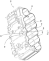
- Fig. 3 shows the support 120 in the housing of the battery pack 100; the support 120 has multiple battery unit accommodating parts 122, the battery unit accommodating parts 122 each being used to accommodate the at least one battery unit 130.
- the support 120 is provided with a first opening 124, the first opening 124 being connected to at least one, preferably two adjacent battery unit accommodating parts 122.
- a thermistor accommodating part is formed by the first opening 124 and a battery unit 130 arranged in the battery unit accommodating part 122 connected to the first opening 124, in particular a wall part of said battery unit 130 at a connected portion, and a thermistor 200 is accommodated in the thermistor accommodating part.
- the thermistor 200 and the battery unit 130 will not be separated by a wall of the support, so the thermistor 200 can be arranged as close as possible to, or even in contact with, the battery unit 130.
- the thermistor accommodating part may be disposed between two adjacent battery unit accommodating parts 122.
- the battery pack 100 may further comprise a printed circuit board 140, on which are arranged electronic components to serve as a control unit for controlling the operation of the battery pack 100.
- the printed circuit board 140 is fixed above the support 120, and located on the same side of the support 120 as the thermistor accommodating part, thereby facilitating the establishment of an electrical connection between the thermistor 200 and the printed circuit board 140, e.g. electrical connection via conducting wires 210, 220 as shown in Fig. 2 .
- the printed circuit board 140 may further be provided with a second opening 142, the second opening 142 of the printed circuit board 140 being substantially aligned with the first opening 124 of the support 120, to facilitate insertion of the thermistor 200 into the thermistor accommodating part through the second opening 142 and the first opening 124.
- the thermistor accommodating part is also filled with thermally conductive glue 400, and a positioning member 300 is provided in the thermistor accommodating part.
- the positioning member 300 is used to limit the position of the thermistor 200, in particular to limit the thermistor 200 in the battery unit accommodating part, so as to prevent or correct shifting of the thermistor 200 in the period of time from filling to solidification of the thermally conductive glue 400, in particular shifting away from the battery unit 130.
- the positioning member 300 and the thermistor 200 are close to each other or have a slight gap therebetween, such that the thermistor 200 can only shift within a limited shifting space in the thermistor accommodating part and finally be positioned in this shifting space, thereby ensuring that the thermistor 200 is positioned relatively accurately, and further ensuring accuracy of temperature measurement.
- this gap is filled with thermally conductive glue 400, thereby avoiding direct contact between the positioning member 300 and the thermistor 200, and preventing pressure on the positioning member 300 from damaging the fragile thermistor 200.
- the first opening 124 may comprise an inclined guide wall part 126. More preferably, in order to facilitate the establishment of the electrical connection between the thermistor 200 and the printed circuit board 140, a notch 128 may also be provided in the guide wall part 126, the notch 128 allowing the conducting wires 210, 220 of the thermistor 200 to pass through.
- the positioning member 300 comprises a body 310 and a protruding part 320, wherein the body 310 has a substantially flat first end 311 and a second end 312 opposite the first end 311; the protruding part 320 extends from the second end 312 in a direction away from the first end 311.
- the second end 312 is further provided with an abutment part 313; the abutment part 313 is different from the protruding part 320, and disposed at an outer side of the protruding part 320, so as to abut the support 120 of the battery pack 100.
- an extending extremity 324 of the protruding part 320 defines a limited shifting space in the thermistor accommodating part, thereby limiting the shifting of the thermistor 200 and the final position thereof.
- the protruding part 320 causes the thermistor 200 to abut the battery unit 130.
- a tapered part 322 is provided at an extremity side of the protruding part 320 close to the extending extremity 324.
- the tapered part 322 conveniently enters a gap between the two adjacent battery unit accommodating parts 122, and is closer to the thermistor 200, as shown in Figs. 4 - 6 ; this also allows the thermistor to be disposed closer to the battery unit, effectively improving the quality of temperature measurement.
- the extending extremity 324 of the protruding part 320 can be as close to the thermistor 200 as possible, and the extent of the shifting space defined by the extending extremity 324 in the thermistor accommodating part is further reduced, thus making the positioning of the thermistor 200 more accurate.
- the configuration of the support 120 is generally fixed and invariable, it is possible to adjust the position of the extending extremity 324 of the protruding part 320, and thereby adjust the extent of the shifting space, by adjusting the configuration of the positioning member 300, in particular the configuration of the tapered part 322, in order to adapt to thermistors 200 with different part numbers, and different use scenarios.
- a channel 340 may be provided between the extending extremity 324 of the protruding part 320 and the first end 311 of the body 310, to allow the conducting wires 210 and 220 of the thermistor 200 to be electrically connected to the printed circuit board 140 via the channel 340.
- the channel 340 may be disposed on a front end 315 of the positioning member 300, as shown in Fig. 5 .
- the protruding part 320 may be formed to be elastic, in which case the protruding part 320 can press the thermistor 200 against the battery unit 130, without damaging the thermistor 200.
- a rib 116 may be provided at an inner side of the housing, for example the upper housing portion 111 here; when the upper housing portion 111, lower housing portion 112, front housing portion 113 and rear housing portion 114 are fitted together to form the housing, so as to accommodate the battery unit 130, the support 120 and the printed circuit board 140, the rib 116 successively passes through the second opening 142 in the printed circuit board 140 and the first opening 124 in the support 120, so as to abut the first end 311 of the positioning member 300, such that the positioning member 300 is pressed against the support 120, facilitating the positioning of the thermistor 200.
- a step of waiting for the thermally conductive glue 400 to solidify can be omitted, and a housing installation step can be performed directly, thus speeding up the overall assembly process.
- a cushioning pad 500 made of foam material for example may be provided between the rib 116 and the first end 311, i.e. above the first end 311, to reduce the effect of housing shocks on the thermistor 200.
- a method of fixing the thermistor 200 in the battery pack 100 comprises: placing the battery unit 130 in the battery unit accommodating part 122; placing the thermistor 200 in the thermistor accommodating part via the second opening 142 and the first opening 124; injecting thermally conductive glue 400 into the thermistor accommodating part via the second opening 142 and the first opening 124; placing the positioning member 300 in the thermistor accommodating part, such that the protruding part 320 of the positioning member 300 faces towards the thermistor 200; pressing the first end 311 of the positioning member 300, so that the abutment part 313 of the second end 312 abuts the support 120, and the thermistor 200 is pushed close to the battery unit 130 and disposed close to the battery unit 130 by means of the positioning member 300, such that the protruding part 320 of the positioning member 300, in particular the extending extremity 324 of the protruding part 320, can limit the position of the thermistor 200.
- At least one housing portion, specifically the upper housing portion 111 may also be mounted to the support 120, for example, after placing the positioning member 300 in the thermistor accommodating part, such that the rib 116 disposed at the inner side of the upper housing portion 111 presses the first end 311 of the positioning member 300.
- the cushioning pad 500 may also be arranged on the first end 311 of the positioning member 300, for example, before mounting the upper housing portion 111 on the support 120.
Landscapes
- Chemical & Material Sciences (AREA)
- Chemical Kinetics & Catalysis (AREA)
- Electrochemistry (AREA)
- General Chemical & Material Sciences (AREA)
- Engineering & Computer Science (AREA)
- Manufacturing & Machinery (AREA)
- Life Sciences & Earth Sciences (AREA)
- Biophysics (AREA)
- Computer Hardware Design (AREA)
- Microelectronics & Electronic Packaging (AREA)
- Battery Mounting, Suspending (AREA)
Abstract
The present invention relates to a battery pack, and a positioning member for a thermistor in the battery pack, wherein the battery pack comprises at least one battery unit and a support, the support having at least one battery unit accommodating part for accommodating the battery unit, wherein the support is provided with a first opening, the first opening is connected to at least one battery unit accommodating part, the first opening and the battery unit of a connected portion form a thermistor accommodating part, and a thermistor arranged close to the battery unit is accommodated in the thermistor accommodating part, and wherein a positioning member is further provided in the thermistor accommodating part, the positioning member being used to limit the thermistor in the battery unit accommodating part.
Description
- The present invention relates to the field of battery pack manufacture, in particular a battery pack, and a positioning member for a thermistor in the battery pack.
- Battery packs are often used to supply power to mobile devices or portable apparatuses, and generally comprise multiple battery units, a support for mounting the multiple battery units, and a control element.
- In addition, in the process of using a battery pack, a phenomenon may occur whereby one or more battery units in the battery pack experience an abnormal rise in temperature. In order to control the temperature of the battery pack promptly, a temperature sensor must be provided inside the battery pack to sense the real-time temperature of the battery pack or battery unit, so that the control unit can perform corresponding adjustment according to the sensed real-time temperature, e.g. cut off the connection between the battery pack and an electrical device, to prevent the temperature of the battery pack from rising further.
- The temperature sensor comprises a thermistor, e.g. a thermistor with a negative temperature coefficient (NTC) or a positive temperature coefficient (PTC). To enable the thermistor to measure the temperature of the battery unit accurately, the thermistor is generally arranged at a position close to the battery unit, e.g. on a support of the battery unit, on an outer side of a housing of the battery unit, etc.
- In the process of making certain battery packs, the thermistor is placed in a gap between two battery units, and a thermally conductive glue is injected; when the thermally conductive glue solidifies, the thermistor is fixed in place. However, when injected, the thermally conductive glue easily causes the thermistor to move, with the result that the thermistor is not in its correct position after solidification of the thermally conductive glue; this will affect the accuracy of temperature measurement.
- An objective of the present invention is to provide a battery pack and a positioning member for a thermistor in the battery pack, whereby the position of the thermistor can be limited when thermally conductive glue solidifies, so that the thermistor is fixed in place at the correct position, thereby ensuring the accuracy of temperature measurement.
- According to a first aspect of the present invention, a battery pack is provided, comprising at least one battery unit and a support, the support having at least one battery unit accommodating part for accommodating the battery unit, wherein the support is provided with a first opening, the first opening is connected to at least one battery unit accommodating part, the first opening and the battery unit of a connected portion form a thermistor accommodating part, and a thermistor arranged close to the battery unit is accommodated in the thermistor accommodating part, and wherein a positioning member is further provided in the thermistor accommodating part, the positioning member being used to limit the thermistor in the battery unit accommodating part.
- Preferably, the first opening is connected to two adjacent said battery unit accommodating parts.
- Preferably, the positioning member extends into a space between two adjacent said battery unit accommodating parts, such that the thermistor is disposed close to or in contact with at least one battery unit.
- Preferably, the positioning member comprises: a body, having a first end and a second end opposite the first end; and a protruding part, extending from the second end in a direction away from the first end.
- Preferably, the second end is further provided with an abutment part different from the protruding part, and the positioning member is arranged so that the abutment part abuts the support to limit a position of the protruding part.
- Preferably, a tapered part is provided at an extremity side of the protruding part. A cross section of the tapered part decreases in size as the thermistor is approached. The tapered part determines the position of an extending extremity of the protruding part, and the limitation of thermistor position by the positioning member can be effectively adjusted by adjusting the configuration of the tapered part.
- Preferably, a channel for accommodating a conducting wire of the thermistor is provided between the extending extremity of the protruding part and the first end of the body. The channel can allow the conducting wire to pass through, so as to conveniently establish an electrical connection between the thermistor and a control unit for example.
- Preferably, the thermistor accommodating part is filled with thermally conductive glue; more preferably, the thermally conductive glue is present between the thermistor accommodating part and the protruding part. This can prevent direct contact between the protruding part and the thermistor, thereby preventing the transmission of forces and shocks sustained by the protruding part to the fragile thermistor, and preventing consequent damage to the thermistor, while the thermally conductive glue can also seal a peripheral gap.
- Preferably, the battery pack further comprises a printed circuit board, the printed circuit board being fixed to the support, and located on the same side of the support as the thermistor accommodating part. This can ensure unhindered electrical connection between the thermistor and the printed circuit board.
- Preferably, a second opening is provided in the printed circuit board, the first opening and the second opening being aligned with each other.
- Preferably, the first opening comprises an inclined guide wall part, to guide the positioning member into the thermistor accommodating part.
- Preferably, the guide wall part is provided with a notch, to pass a conducting wire of the thermistor through, so as to conveniently establish an electrical connection between the thermistor and the printed circuit board for example.
- Preferably, the battery pack further comprises at least one housing portion, the at least one housing portion being provided with a rib capable of passing through the second opening and the first opening to abut the first end of the positioning member. Thus, a step of waiting for the thermally conductive glue to solidify can be effectively omitted, and a housing installation step can be performed directly, thus speeding up the overall assembly process.
- Preferably, a cushioning pad is provided between the first end of the positioning member and the rib, to reduce the effect of housing shocks on the thermistor.
- Preferably, the protruding part is elastic, so the protruding part can press the thermistor against the battery unit, without damaging the thermistor.
- Preferably, the protruding part causes the thermistor to abut the battery unit.
- According to a second aspect of the present invention, a positioning member for a thermistor in the battery pack of the first aspect of the present invention is provided, the positioning member being able to limit the thermistor to be close to or in contact with the battery unit, and the positioning member comprising: a body, having a first end and a second end opposite the first end; and a protruding part, extending from the second end in a direction away from the first end, so as to limit a position of the thermistor, wherein the second end is further provided with an abutment part different from the protruding part, to abut the support of the battery pack.
- Preferably, a tapered part is provided at an extremity side of the protruding part. A cross section of the tapered part decreases in size as the thermistor is approached. The tapered part determines the position of an extending extremity of the protruding part, and the limitation of thermistor position by the positioning member can be effectively adjusted by adjusting the configuration of the tapered part.
- Preferably, a channel is provided between an extending extremity of the protruding part and the first end of the body. The channel can allow the conducting wire to pass through, so as to conveniently establish an electrical connection between the thermistor and a control unit for example.
- In addition to enabling the thermistor to be fixed in place at the correct position, thereby ensuring the accuracy of temperature measurement, the battery pack and member according to the present invention may also have the following advantages:
- 1. The configuration of the positioning member can be adjusted to adapt to thermistors with different part numbers, and different use scenarios;
- 2. The fragile thermistor can be effectively protected from damage due to squeezing, shocks, etc.;
- 3. An electrical connection between the thermistor and the printed circuit board (control unit) can be established without hindrance; and
- 4. The overall assembly process can be speeded up.
- Preferred embodiments of the present invention are described in more detail below with reference to the drawings. In the drawings, identical reference labels denote identical components. Those skilled in the art should understand that the drawings are intended to illustrate preferred embodiments of the present invention schematically, and have no limiting effect on the scope of the present invention, and the various components in the drawings are not drawn to scale. In the drawings:
-
Fig. 1 shows a schematic three-dimensional drawing of a battery pack according to an embodiment of the present invention; -
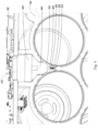
Fig. 2 shows a sectional view of the battery pack inFig. 1 , taken along line A-A; -
Fig. 3 shows a three-dimensional drawing of the support of the battery pack inFig. 1 ; -
Fig. 4 shows a partial cutaway three-dimensional drawing of the structure of the support inFig. 3 close to the thermistor, and is intended to show how the positioning member according to the present invention is positioned relative to the surrounding structure; -
Fig. 5 shows a three-dimensional drawing of the positioning member according to the present invention; and -
Fig. 6 shows a three-dimensional drawing of the positioning member according to the present invention, viewed from another direction. - Specific embodiments of the present invention are now described in detail by referring to the drawings. The embodiments described herein are merely preferred embodiments of the present invention. Based on these preferred embodiments, those skilled in the art will be able to think of other ways in which the present invention could be implemented, all of which likewise fall within the scope of the present invention.
-
Figs. 1 and2 show abattery pack 100 according to the present invention, comprising a housing and, located within the housing, asupport 120 and at least onebattery unit 130, wherein the housing is formed by anupper housing portion 111, alower housing portion 112, afront housing portion 113 and arear housing portion 114. Theupper housing portion 111,lower housing portion 112,front housing portion 113 andrear housing portion 114 are for example fixed to thesupport 120 separately by means of screws or mounting pins, thereby forming the housing of thebattery pack 100. - In other embodiments, the housing may be formed of one, two, three or more housing portions.
-
Fig. 3 shows thesupport 120 in the housing of thebattery pack 100; thesupport 120 has multiple batteryunit accommodating parts 122, the batteryunit accommodating parts 122 each being used to accommodate the at least onebattery unit 130. - The
support 120 is provided with afirst opening 124, thefirst opening 124 being connected to at least one, preferably two adjacent batteryunit accommodating parts 122. A thermistor accommodating part is formed by thefirst opening 124 and abattery unit 130 arranged in the batteryunit accommodating part 122 connected to thefirst opening 124, in particular a wall part of saidbattery unit 130 at a connected portion, and athermistor 200 is accommodated in the thermistor accommodating part. Thus, thethermistor 200 and thebattery unit 130 will not be separated by a wall of the support, so thethermistor 200 can be arranged as close as possible to, or even in contact with, thebattery unit 130. The thermistor accommodating part may be disposed between two adjacent batteryunit accommodating parts 122. - Returning to
Fig. 2 , thebattery pack 100 may further comprise a printedcircuit board 140, on which are arranged electronic components to serve as a control unit for controlling the operation of thebattery pack 100. The printedcircuit board 140 is fixed above thesupport 120, and located on the same side of thesupport 120 as the thermistor accommodating part, thereby facilitating the establishment of an electrical connection between thethermistor 200 and the printedcircuit board 140, e.g. electrical connection via conductingwires Fig. 2 . - The printed
circuit board 140 may further be provided with asecond opening 142, thesecond opening 142 of the printedcircuit board 140 being substantially aligned with thefirst opening 124 of thesupport 120, to facilitate insertion of thethermistor 200 into the thermistor accommodating part through thesecond opening 142 and thefirst opening 124. - The thermistor accommodating part is also filled with thermally
conductive glue 400, and apositioning member 300 is provided in the thermistor accommodating part. The positioningmember 300 is used to limit the position of thethermistor 200, in particular to limit thethermistor 200 in the battery unit accommodating part, so as to prevent or correct shifting of thethermistor 200 in the period of time from filling to solidification of the thermallyconductive glue 400, in particular shifting away from thebattery unit 130. In particular, the positioningmember 300 and thethermistor 200 are close to each other or have a slight gap therebetween, such that thethermistor 200 can only shift within a limited shifting space in the thermistor accommodating part and finally be positioned in this shifting space, thereby ensuring that thethermistor 200 is positioned relatively accurately, and further ensuring accuracy of temperature measurement. - Furthermore, preferably, since there is a certain gap between the positioning
member 300 and thethermistor 200, this gap is filled with thermallyconductive glue 400, thereby avoiding direct contact between the positioningmember 300 and thethermistor 200, and preventing pressure on thepositioning member 300 from damaging thefragile thermistor 200. - Referring to
Fig. 3 , in order to guide thepositioning member 300 into the thermistor accommodating part, thefirst opening 124 may comprise an inclinedguide wall part 126. More preferably, in order to facilitate the establishment of the electrical connection between thethermistor 200 and the printedcircuit board 140, anotch 128 may also be provided in theguide wall part 126, thenotch 128 allowing the conductingwires thermistor 200 to pass through. - Referring to
Figs. 4 - 6 , the configuration of thepositioning member 300 can be seen more clearly. - The positioning
member 300 comprises abody 310 and aprotruding part 320, wherein thebody 310 has a substantially flatfirst end 311 and asecond end 312 opposite thefirst end 311; the protrudingpart 320 extends from thesecond end 312 in a direction away from thefirst end 311. Thesecond end 312 is further provided with anabutment part 313; theabutment part 313 is different from the protrudingpart 320, and disposed at an outer side of theprotruding part 320, so as to abut thesupport 120 of thebattery pack 100. When theabutment part 313 abuts thesupport 120, an extendingextremity 324 of theprotruding part 320 defines a limited shifting space in the thermistor accommodating part, thereby limiting the shifting of thethermistor 200 and the final position thereof. Optionally, the protrudingpart 320 causes thethermistor 200 to abut thebattery unit 130. - Preferably, a
tapered part 322 is provided at an extremity side of theprotruding part 320 close to the extendingextremity 324. In particular, in the case where the thermistor accommodating part is disposed between two adjacent batteryunit accommodating parts 122, thetapered part 322 conveniently enters a gap between the two adjacent batteryunit accommodating parts 122, and is closer to thethermistor 200, as shown inFigs. 4 - 6 ; this also allows the thermistor to be disposed closer to the battery unit, effectively improving the quality of temperature measurement. Thus, the extendingextremity 324 of theprotruding part 320 can be as close to thethermistor 200 as possible, and the extent of the shifting space defined by the extendingextremity 324 in the thermistor accommodating part is further reduced, thus making the positioning of thethermistor 200 more accurate. - Furthermore, in a scenario in which the configuration of the
support 120 is generally fixed and invariable, it is possible to adjust the position of the extendingextremity 324 of theprotruding part 320, and thereby adjust the extent of the shifting space, by adjusting the configuration of thepositioning member 300, in particular the configuration of thetapered part 322, in order to adapt tothermistors 200 with different part numbers, and different use scenarios. - Preferably, a
channel 340 may be provided between the extendingextremity 324 of theprotruding part 320 and thefirst end 311 of thebody 310, to allow the conductingwires thermistor 200 to be electrically connected to the printedcircuit board 140 via thechannel 340. For example, thechannel 340 may be disposed on afront end 315 of thepositioning member 300, as shown inFig. 5 . - In an embodiment, the protruding
part 320 may be formed to be elastic, in which case the protrudingpart 320 can press thethermistor 200 against thebattery unit 130, without damaging thethermistor 200. - Again returning to
Fig. 2 , preferably, arib 116 may be provided at an inner side of the housing, for example theupper housing portion 111 here; when theupper housing portion 111,lower housing portion 112,front housing portion 113 andrear housing portion 114 are fitted together to form the housing, so as to accommodate thebattery unit 130, thesupport 120 and the printedcircuit board 140, therib 116 successively passes through thesecond opening 142 in the printedcircuit board 140 and thefirst opening 124 in thesupport 120, so as to abut thefirst end 311 of thepositioning member 300, such that thepositioning member 300 is pressed against thesupport 120, facilitating the positioning of thethermistor 200. Thus, after filling with the thermallyconductive glue 400, a step of waiting for the thermallyconductive glue 400 to solidify can be omitted, and a housing installation step can be performed directly, thus speeding up the overall assembly process. - More preferably, a
cushioning pad 500 made of foam material for example may be provided between therib 116 and thefirst end 311, i.e. above thefirst end 311, to reduce the effect of housing shocks on thethermistor 200. - A method of fixing the
thermistor 200 in thebattery pack 100 according to the present invention is described below. The method comprises: placing thebattery unit 130 in the batteryunit accommodating part 122; placing thethermistor 200 in the thermistor accommodating part via thesecond opening 142 and thefirst opening 124; injecting thermallyconductive glue 400 into the thermistor accommodating part via thesecond opening 142 and thefirst opening 124; placing thepositioning member 300 in the thermistor accommodating part, such that theprotruding part 320 of thepositioning member 300 faces towards thethermistor 200; pressing thefirst end 311 of thepositioning member 300, so that theabutment part 313 of thesecond end 312 abuts thesupport 120, and thethermistor 200 is pushed close to thebattery unit 130 and disposed close to thebattery unit 130 by means of thepositioning member 300, such that theprotruding part 320 of thepositioning member 300, in particular the extendingextremity 324 of theprotruding part 320, can limit the position of thethermistor 200. Thereafter, the pressure on thepositioning member 300 is maintained, until the thermallyconductive glue 400 solidifies. - In order to speed up the overall assembly process, at least one housing portion, specifically the
upper housing portion 111 may also be mounted to thesupport 120, for example, after placing thepositioning member 300 in the thermistor accommodating part, such that therib 116 disposed at the inner side of theupper housing portion 111 presses thefirst end 311 of thepositioning member 300. - In order to reduce the effect of housing shocks on the
thermistor 200, thecushioning pad 500 may also be arranged on thefirst end 311 of thepositioning member 300, for example, before mounting theupper housing portion 111 on thesupport 120. - The above description of various embodiments of the present invention is provided for illustrative purposes to a person skilled in the art. It is not intended that the present invention be exclusive or limited to a single disclosed embodiment. As mentioned above, those skilled in the art will understand various alternatives and variations of the present invention. Thus, although some alternative embodiments have been specifically described, those skilled in the art will understand, or develop with relative ease, other embodiments. The present invention is intended to include all alternatives, modifications and variants of the present invention described here, as well as other embodiments which fall within the spirit and scope of the present invention described above.
-
- 100
- Battery pack
- 111
- Upper housing portion
- 112
- Lower housing portion
- 113
- Front housing portion
- 114
- Rear housing portion
- 116
- Rib
- 120
- Support
- 122
- Battery unit accommodating part
- 124
- First opening
- 126
- Guide wall part
- 128
- Notch
- 130
- Battery unit
- 140
- Printed circuit board
- 142
- Second opening
- 200
- Thermistor
- 210
- Conducting wire
- 220
- Conducting wire
- 300
- Positioning member
- 310
- Body
- 311
- First end
- 312
- Second end
- 313
- Abutment part
- 315
- Front end
- 320
- Protruding part
- 322
- Tapered part
- 324
- Extending extremity
- 400
- Thermally conductive glue
- 500
- Cushioning pad
Claims (15)
- Battery pack, comprising:at least one battery unit; anda support, having at least one battery unit accommodating part for accommodating the battery unit,wherein the support is provided with a first opening, the first opening is connected to at least one battery unit accommodating part, the first opening and the battery unit of a connected portion form a thermistor accommodating part, and a thermistor arranged close to the battery unit is accommodated in the thermistor accommodating part, characterized in that a positioning member is further provided in the thermistor accommodating part, the positioning member being used to limit the thermistor in the battery unit accommodating part.
- Battery pack according to Claim 1, characterized in that the first opening is connected to two adjacent said battery unit accommodating parts.
- Battery pack according to Claim 1 or 2, characterized in that the positioning member extends into a space between two adjacent said battery unit accommodating parts, such that the thermistor is disposed close to or in contact with at least one battery unit, and preferably, the positioning member comprises:a body, having a first end and a second end opposite the first end; anda protruding part, extending from the second end in a direction away from the first end.
- Battery pack according to Claim 3, characterized in that the second end is further provided with an abutment part different from the protruding part, and the positioning member is arranged so that the abutment part abuts the support to limit a position of the protruding part, and preferably, a tapered part is provided at an extremity side of the protruding part.
- Battery pack according to Claim 4, characterized in that a channel for accommodating a conducting wire of the thermistor is provided between an extending extremity of the protruding part and the first end of the body.
- Battery pack according to Claim 4, characterized in that the thermistor accommodating part is filled with thermally conductive glue, and preferably, the thermally conductive glue is present between the thermistor accommodating part and the protruding part.
- Battery pack according to Claim 4, characterized in that the battery pack further comprises a printed circuit board, the printed circuit board being fixed to the support, and located on the same side of the support as the thermistor accommodating part, and preferably, a second opening is provided in the printed circuit board, the first opening and the second opening being aligned with each other.
- Battery pack according to Claim 7, characterized in that the first opening comprises an inclined guide wall part, to guide the positioning member into the thermistor accommodating part, and preferably, the guide wall part is provided with a notch, to pass a conducting wire of the thermistor through.
- Battery pack according to Claim 7, characterized in that the battery pack further comprises at least one housing portion, the at least one housing portion being provided with a rib capable of passing through the second opening and the first opening to abut the first end of the positioning member.
- Battery pack according to Claim 9, characterized in that a cushioning pad is provided between the first end of the positioning member and the rib.
- Battery pack according to Claim 3, characterized in that the protruding part is elastic.
- Battery pack according to Claim 11, characterized in that the protruding part causes the thermistor to abut the battery unit.
- Positioning member for a thermistor in the battery pack according to Claim 1, characterized in that the positioning member is used to limit the thermistor to be close to or in contact with the battery unit, the positioning member comprising:a body, having a first end and a second end opposite the first end; anda protruding part, extending from the second end in a direction away from the first end, so as to limit a position of the thermistor,wherein the second end is further provided with an abutment part different from the protruding part, to abut the support of the battery pack.
- Positioning member according to Claim 13, characterized in that a tapered part is provided at an extremity side of the protruding part.
- Positioning member according to Claim 14, characterized in that a channel is provided between an extending extremity of the protruding part and the first end of the body.
Applications Claiming Priority (1)
| Application Number | Priority Date | Filing Date | Title |
|---|---|---|---|
| CN202310115487.7A CN118507881A (en) | 2023-02-14 | 2023-02-14 | Battery pack and positioning member for thermistor in battery pack |
Publications (1)
| Publication Number | Publication Date |
|---|---|
| EP4418421A1 true EP4418421A1 (en) | 2024-08-21 |
Family
ID=89941262
Family Applications (1)
| Application Number | Title | Priority Date | Filing Date |
|---|---|---|---|
| EP24157614.9A Pending EP4418421A1 (en) | 2023-02-14 | 2024-02-14 | Battery pack, and positioning member for thermistor in same |
Country Status (5)
| Country | Link |
|---|---|
| US (1) | US20240274905A1 (en) |
| EP (1) | EP4418421A1 (en) |
| CN (1) | CN118507881A (en) |
| AU (1) | AU2024200790A1 (en) |
| DE (1) | DE102024104013A1 (en) |
Families Citing this family (1)
| Publication number | Priority date | Publication date | Assignee | Title |
|---|---|---|---|---|
| KR20260026991A (en) * | 2024-08-20 | 2026-02-27 | 삼성에스디아이 주식회사 | battery pack |
Citations (3)
| Publication number | Priority date | Publication date | Assignee | Title |
|---|---|---|---|---|
| US20060028183A1 (en) * | 2004-07-23 | 2006-02-09 | Ryosaku Izawa | Battery device of vehicle power supply |
| US20090117452A1 (en) * | 2005-09-21 | 2009-05-07 | Bernd Wiesner | Rechargeable Battery Pack and Electrical Hand Tool Device |
| US20120141839A1 (en) * | 2010-12-01 | 2012-06-07 | Samsung Sdi Co., Ltd. | Battery case and battery pack using the same |
Family Cites Families (3)
| Publication number | Priority date | Publication date | Assignee | Title |
|---|---|---|---|---|
| US6607302B2 (en) * | 2001-09-24 | 2003-08-19 | Visteon Global Technologies, Inc. | Temperature sensor housing design |
| KR102866740B1 (en) * | 2020-08-11 | 2025-09-29 | 주식회사 엘지에너지솔루션 | Battery module with imploved assembly and battery pack including the same |
| KR20230149514A (en) * | 2022-04-20 | 2023-10-27 | 에스케이온 주식회사 | Battery Module Having Sensing Module Assembly |
-
2023
- 2023-02-14 CN CN202310115487.7A patent/CN118507881A/en active Pending
-
2024
- 2024-02-08 AU AU2024200790A patent/AU2024200790A1/en active Pending
- 2024-02-09 US US18/437,963 patent/US20240274905A1/en active Pending
- 2024-02-13 DE DE102024104013.0A patent/DE102024104013A1/en active Pending
- 2024-02-14 EP EP24157614.9A patent/EP4418421A1/en active Pending
Patent Citations (3)
| Publication number | Priority date | Publication date | Assignee | Title |
|---|---|---|---|---|
| US20060028183A1 (en) * | 2004-07-23 | 2006-02-09 | Ryosaku Izawa | Battery device of vehicle power supply |
| US20090117452A1 (en) * | 2005-09-21 | 2009-05-07 | Bernd Wiesner | Rechargeable Battery Pack and Electrical Hand Tool Device |
| US20120141839A1 (en) * | 2010-12-01 | 2012-06-07 | Samsung Sdi Co., Ltd. | Battery case and battery pack using the same |
Also Published As
| Publication number | Publication date |
|---|---|
| CN118507881A (en) | 2024-08-16 |
| US20240274905A1 (en) | 2024-08-15 |
| AU2024200790A1 (en) | 2024-08-29 |
| DE102024104013A1 (en) | 2024-08-14 |
Similar Documents
| Publication | Publication Date | Title |
|---|---|---|
| JP6970875B2 (en) | Capacitor | |
| CN109073477B (en) | Temperature detection device | |
| CN107078244B (en) | Battery pack | |
| CN205861226U (en) | Temperature measuring equipment, electric appliance component and battery bag | |
| US20240274905A1 (en) | Battery pack, and positioning member for thermistor in same | |
| JP7022790B2 (en) | battery pack | |
| US9316544B2 (en) | Electronic thermometer and method for manufacturing the same | |
| JP6559181B2 (en) | Temperature sensor and battery pack | |
| US12512567B2 (en) | Battery connection module | |
| CN107607215B (en) | Temperature measuring components, temperature measuring devices and electrical components | |
| JP3185917U (en) | Protective device | |
| JP4940017B2 (en) | Manufacturing method of electronic unit | |
| KR100586128B1 (en) | Mounting structure of the temperature fuse to the circuit board | |
| JP4830662B2 (en) | Plastic molded product with metal plate | |
| KR20160019826A (en) | Terminal block for temperature compensating of thermocouple | |
| US6734781B1 (en) | Mounting structure for temperature-sensitive fuse on circuit board | |
| JP2005183176A (en) | Battery pack and manufacturing method of same | |
| US12416531B2 (en) | Temperature sensor, temperature detection device and image formation device | |
| JP2018179938A (en) | Temperature sensor and battery pack | |
| JP2019219201A (en) | Sensor body and manufacturing method for sensor body | |
| JP2011204525A (en) | Thin connector | |
| CN103119409B (en) | Electronic thermometer and manufacturing method thereof | |
| JP2003077436A (en) | Battery pack and method of manufacturing the same | |
| KR101651262B1 (en) | Temperature measurable device | |
| CN101320700A (en) | Method and molding tool for manufacturing electronic device having resin molded case |
Legal Events
| Date | Code | Title | Description |
|---|---|---|---|
| PUAI | Public reference made under article 153(3) epc to a published international application that has entered the european phase |
Free format text: ORIGINAL CODE: 0009012 |
|
| STAA | Information on the status of an ep patent application or granted ep patent |
Free format text: STATUS: THE APPLICATION HAS BEEN PUBLISHED |
|
| AK | Designated contracting states |
Kind code of ref document: A1 Designated state(s): AL AT BE BG CH CY CZ DE DK EE ES FI FR GB GR HR HU IE IS IT LI LT LU LV MC ME MK MT NL NO PL PT RO RS SE SI SK SM TR |
|
| STAA | Information on the status of an ep patent application or granted ep patent |
Free format text: STATUS: REQUEST FOR EXAMINATION WAS MADE |
|
| 17P | Request for examination filed |
Effective date: 20250509 |