EP4418413A1 - Electric storage device - Google Patents
Electric storage device Download PDFInfo
- Publication number
- EP4418413A1 EP4418413A1 EP24153720.8A EP24153720A EP4418413A1 EP 4418413 A1 EP4418413 A1 EP 4418413A1 EP 24153720 A EP24153720 A EP 24153720A EP 4418413 A1 EP4418413 A1 EP 4418413A1
- Authority
- EP
- European Patent Office
- Prior art keywords
- negative electrode
- electrode body
- storage device
- positive electrode
- electric storage
- Prior art date
- Legal status (The legal status is an assumption and is not a legal conclusion. Google has not performed a legal analysis and makes no representation as to the accuracy of the status listed.)
- Pending
Links
Images



Classifications
-
- H—ELECTRICITY
- H01—ELECTRIC ELEMENTS
- H01G—CAPACITORS; CAPACITORS, RECTIFIERS, DETECTORS, SWITCHING DEVICES, LIGHT-SENSITIVE OR TEMPERATURE-SENSITIVE DEVICES OF THE ELECTROLYTIC TYPE
- H01G11/00—Hybrid capacitors, i.e. capacitors having different positive and negative electrodes; Electric double-layer [EDL] capacitors; Processes for the manufacture thereof or of parts thereof
- H01G11/22—Electrodes
- H01G11/26—Electrodes characterised by their structure, e.g. multi-layered, porosity or surface features
-
- H—ELECTRICITY
- H01—ELECTRIC ELEMENTS
- H01M—PROCESSES OR MEANS, e.g. BATTERIES, FOR THE DIRECT CONVERSION OF CHEMICAL ENERGY INTO ELECTRICAL ENERGY
- H01M50/00—Constructional details or processes of manufacture of the non-active parts of electrochemical cells other than fuel cells, e.g. hybrid cells
- H01M50/10—Primary casings; Jackets or wrappings
- H01M50/172—Arrangements of electric connectors penetrating the casing
- H01M50/174—Arrangements of electric connectors penetrating the casing adapted for the shape of the cells
- H01M50/176—Arrangements of electric connectors penetrating the casing adapted for the shape of the cells for prismatic or rectangular cells
-
- H—ELECTRICITY
- H01—ELECTRIC ELEMENTS
- H01G—CAPACITORS; CAPACITORS, RECTIFIERS, DETECTORS, SWITCHING DEVICES, LIGHT-SENSITIVE OR TEMPERATURE-SENSITIVE DEVICES OF THE ELECTROLYTIC TYPE
- H01G11/00—Hybrid capacitors, i.e. capacitors having different positive and negative electrodes; Electric double-layer [EDL] capacitors; Processes for the manufacture thereof or of parts thereof
- H01G11/74—Terminals, e.g. extensions of current collectors
-
- H—ELECTRICITY
- H01—ELECTRIC ELEMENTS
- H01G—CAPACITORS; CAPACITORS, RECTIFIERS, DETECTORS, SWITCHING DEVICES, LIGHT-SENSITIVE OR TEMPERATURE-SENSITIVE DEVICES OF THE ELECTROLYTIC TYPE
- H01G11/00—Hybrid capacitors, i.e. capacitors having different positive and negative electrodes; Electric double-layer [EDL] capacitors; Processes for the manufacture thereof or of parts thereof
- H01G11/78—Cases; Housings; Encapsulations; Mountings
- H01G11/82—Fixing or assembling a capacitive element in a housing, e.g. mounting electrodes, current collectors or terminals in containers or encapsulations
-
- H—ELECTRICITY
- H01—ELECTRIC ELEMENTS
- H01M—PROCESSES OR MEANS, e.g. BATTERIES, FOR THE DIRECT CONVERSION OF CHEMICAL ENERGY INTO ELECTRICAL ENERGY
- H01M10/00—Secondary cells; Manufacture thereof
- H01M10/04—Construction or manufacture in general
- H01M10/0431—Cells with wound or folded electrodes
-
- H—ELECTRICITY
- H01—ELECTRIC ELEMENTS
- H01M—PROCESSES OR MEANS, e.g. BATTERIES, FOR THE DIRECT CONVERSION OF CHEMICAL ENERGY INTO ELECTRICAL ENERGY
- H01M10/00—Secondary cells; Manufacture thereof
- H01M10/05—Accumulators with non-aqueous electrolyte
- H01M10/052—Li-accumulators
-
- H—ELECTRICITY
- H01—ELECTRIC ELEMENTS
- H01M—PROCESSES OR MEANS, e.g. BATTERIES, FOR THE DIRECT CONVERSION OF CHEMICAL ENERGY INTO ELECTRICAL ENERGY
- H01M10/00—Secondary cells; Manufacture thereof
- H01M10/05—Accumulators with non-aqueous electrolyte
- H01M10/052—Li-accumulators
- H01M10/0525—Rocking-chair batteries, i.e. batteries with lithium insertion or intercalation in both electrodes; Lithium-ion batteries
-
- H—ELECTRICITY
- H01—ELECTRIC ELEMENTS
- H01M—PROCESSES OR MEANS, e.g. BATTERIES, FOR THE DIRECT CONVERSION OF CHEMICAL ENERGY INTO ELECTRICAL ENERGY
- H01M10/00—Secondary cells; Manufacture thereof
- H01M10/05—Accumulators with non-aqueous electrolyte
- H01M10/058—Construction or manufacture
- H01M10/0587—Construction or manufacture of accumulators having only wound construction elements, i.e. wound positive electrodes, wound negative electrodes and wound separators
-
- H—ELECTRICITY
- H01—ELECTRIC ELEMENTS
- H01M—PROCESSES OR MEANS, e.g. BATTERIES, FOR THE DIRECT CONVERSION OF CHEMICAL ENERGY INTO ELECTRICAL ENERGY
- H01M4/00—Electrodes
- H01M4/02—Electrodes composed of, or comprising, active material
-
- H—ELECTRICITY
- H01—ELECTRIC ELEMENTS
- H01M—PROCESSES OR MEANS, e.g. BATTERIES, FOR THE DIRECT CONVERSION OF CHEMICAL ENERGY INTO ELECTRICAL ENERGY
- H01M4/00—Electrodes
- H01M4/02—Electrodes composed of, or comprising, active material
- H01M4/13—Electrodes for accumulators with non-aqueous electrolyte, e.g. for lithium-accumulators; Processes of manufacture thereof
-
- H—ELECTRICITY
- H01—ELECTRIC ELEMENTS
- H01M—PROCESSES OR MEANS, e.g. BATTERIES, FOR THE DIRECT CONVERSION OF CHEMICAL ENERGY INTO ELECTRICAL ENERGY
- H01M50/00—Constructional details or processes of manufacture of the non-active parts of electrochemical cells other than fuel cells, e.g. hybrid cells
- H01M50/10—Primary casings; Jackets or wrappings
- H01M50/102—Primary casings; Jackets or wrappings characterised by their shape or physical structure
- H01M50/103—Primary casings; Jackets or wrappings characterised by their shape or physical structure prismatic or rectangular
-
- H—ELECTRICITY
- H01—ELECTRIC ELEMENTS
- H01M—PROCESSES OR MEANS, e.g. BATTERIES, FOR THE DIRECT CONVERSION OF CHEMICAL ENERGY INTO ELECTRICAL ENERGY
- H01M50/00—Constructional details or processes of manufacture of the non-active parts of electrochemical cells other than fuel cells, e.g. hybrid cells
- H01M50/10—Primary casings; Jackets or wrappings
- H01M50/147—Lids or covers
- H01M50/166—Lids or covers characterised by the methods of assembling casings with lids
- H01M50/169—Lids or covers characterised by the methods of assembling casings with lids by welding, brazing or soldering
-
- H—ELECTRICITY
- H01—ELECTRIC ELEMENTS
- H01M—PROCESSES OR MEANS, e.g. BATTERIES, FOR THE DIRECT CONVERSION OF CHEMICAL ENERGY INTO ELECTRICAL ENERGY
- H01M50/00—Constructional details or processes of manufacture of the non-active parts of electrochemical cells other than fuel cells, e.g. hybrid cells
- H01M50/10—Primary casings; Jackets or wrappings
- H01M50/183—Sealing members
- H01M50/184—Sealing members characterised by their shape or structure
-
- H—ELECTRICITY
- H01—ELECTRIC ELEMENTS
- H01M—PROCESSES OR MEANS, e.g. BATTERIES, FOR THE DIRECT CONVERSION OF CHEMICAL ENERGY INTO ELECTRICAL ENERGY
- H01M50/00—Constructional details or processes of manufacture of the non-active parts of electrochemical cells other than fuel cells, e.g. hybrid cells
- H01M50/50—Current conducting connections for cells or batteries
- H01M50/528—Fixed electrical connections, i.e. not intended for disconnection
-
- H—ELECTRICITY
- H01—ELECTRIC ELEMENTS
- H01M—PROCESSES OR MEANS, e.g. BATTERIES, FOR THE DIRECT CONVERSION OF CHEMICAL ENERGY INTO ELECTRICAL ENERGY
- H01M50/00—Constructional details or processes of manufacture of the non-active parts of electrochemical cells other than fuel cells, e.g. hybrid cells
- H01M50/50—Current conducting connections for cells or batteries
- H01M50/531—Electrode connections inside a battery casing
-
- H—ELECTRICITY
- H01—ELECTRIC ELEMENTS
- H01M—PROCESSES OR MEANS, e.g. BATTERIES, FOR THE DIRECT CONVERSION OF CHEMICAL ENERGY INTO ELECTRICAL ENERGY
- H01M50/00—Constructional details or processes of manufacture of the non-active parts of electrochemical cells other than fuel cells, e.g. hybrid cells
- H01M50/50—Current conducting connections for cells or batteries
- H01M50/531—Electrode connections inside a battery casing
- H01M50/538—Connection of several leads or tabs of wound or folded electrode stacks
-
- H—ELECTRICITY
- H01—ELECTRIC ELEMENTS
- H01M—PROCESSES OR MEANS, e.g. BATTERIES, FOR THE DIRECT CONVERSION OF CHEMICAL ENERGY INTO ELECTRICAL ENERGY
- H01M50/00—Constructional details or processes of manufacture of the non-active parts of electrochemical cells other than fuel cells, e.g. hybrid cells
- H01M50/50—Current conducting connections for cells or batteries
- H01M50/543—Terminals
- H01M50/552—Terminals characterised by their shape
- H01M50/553—Terminals adapted for prismatic, pouch or rectangular cells
-
- H—ELECTRICITY
- H01—ELECTRIC ELEMENTS
- H01M—PROCESSES OR MEANS, e.g. BATTERIES, FOR THE DIRECT CONVERSION OF CHEMICAL ENERGY INTO ELECTRICAL ENERGY
- H01M50/00—Constructional details or processes of manufacture of the non-active parts of electrochemical cells other than fuel cells, e.g. hybrid cells
- H01M50/50—Current conducting connections for cells or batteries
- H01M50/543—Terminals
- H01M50/564—Terminals characterised by their manufacturing process
- H01M50/566—Terminals characterised by their manufacturing process by welding, soldering or brazing
-
- H—ELECTRICITY
- H01—ELECTRIC ELEMENTS
- H01M—PROCESSES OR MEANS, e.g. BATTERIES, FOR THE DIRECT CONVERSION OF CHEMICAL ENERGY INTO ELECTRICAL ENERGY
- H01M50/00—Constructional details or processes of manufacture of the non-active parts of electrochemical cells other than fuel cells, e.g. hybrid cells
- H01M50/10—Primary casings; Jackets or wrappings
- H01M50/147—Lids or covers
-
- H—ELECTRICITY
- H01—ELECTRIC ELEMENTS
- H01M—PROCESSES OR MEANS, e.g. BATTERIES, FOR THE DIRECT CONVERSION OF CHEMICAL ENERGY INTO ELECTRICAL ENERGY
- H01M50/00—Constructional details or processes of manufacture of the non-active parts of electrochemical cells other than fuel cells, e.g. hybrid cells
- H01M50/50—Current conducting connections for cells or batteries
- H01M50/543—Terminals
- H01M50/547—Terminals characterised by the disposition of the terminals on the cells
- H01M50/55—Terminals characterised by the disposition of the terminals on the cells on the same side of the cell
-
- Y—GENERAL TAGGING OF NEW TECHNOLOGICAL DEVELOPMENTS; GENERAL TAGGING OF CROSS-SECTIONAL TECHNOLOGIES SPANNING OVER SEVERAL SECTIONS OF THE IPC; TECHNICAL SUBJECTS COVERED BY FORMER USPC CROSS-REFERENCE ART COLLECTIONS [XRACs] AND DIGESTS
- Y02—TECHNOLOGIES OR APPLICATIONS FOR MITIGATION OR ADAPTATION AGAINST CLIMATE CHANGE
- Y02E—REDUCTION OF GREENHOUSE GAS [GHG] EMISSIONS, RELATED TO ENERGY GENERATION, TRANSMISSION OR DISTRIBUTION
- Y02E60/00—Enabling technologies; Technologies with a potential or indirect contribution to GHG emissions mitigation
- Y02E60/10—Energy storage using batteries
-
- Y—GENERAL TAGGING OF NEW TECHNOLOGICAL DEVELOPMENTS; GENERAL TAGGING OF CROSS-SECTIONAL TECHNOLOGIES SPANNING OVER SEVERAL SECTIONS OF THE IPC; TECHNICAL SUBJECTS COVERED BY FORMER USPC CROSS-REFERENCE ART COLLECTIONS [XRACs] AND DIGESTS
- Y02—TECHNOLOGIES OR APPLICATIONS FOR MITIGATION OR ADAPTATION AGAINST CLIMATE CHANGE
- Y02P—CLIMATE CHANGE MITIGATION TECHNOLOGIES IN THE PRODUCTION OR PROCESSING OF GOODS
- Y02P70/00—Climate change mitigation technologies in the production process for final industrial or consumer products
- Y02P70/50—Manufacturing or production processes characterised by the final manufactured product
Definitions
- the present disclosure relates to an electric storage device.
- the electric storage device includes an electrode body having a pair of opposed wide width surfaces, includes a case configured to accommodate the electrode body, and includes a terminal electrically connected to the electrode body.
- Japanese Patent Publication 2022-44958 discloses a battery (an electric storage device) including an electrode body, a battery case (a case), and an electrical collector terminal, which is a technique having an object to implement a space efficiency in the case and to suppress a breakage on an electrode electrical collector body (tab) portion.
- the above described electric storage device includes the electrical collector terminal (below, referred to as "electrical collector body", too), and thus a number of parts is increased so as to cause an increase in an electric resistance.
- a herein present disclosure has been made in view of the above-described circumstances, and the object is to provide an electric storage device that can compatibly implement enhancing the space efficiency and suppressing the increase in the electric resistance.
- a herein disclosed electric storage device includes an electrode body in which a long sheet-shaped positive electrode and a long sheet-shaped negative electrode are wound in a sheet longitudinal direction via a separator and which has a pair of opposed wide width surfaces, includes a case which is formed in a hexahedron shape, which is configured to accommodate the electrode body, and which has an exterior package having a first surface formed in a wide width rectangular shape, an opening opposed to the first surface, a pair of opposed second surfaces extending from an outer edge of the first surface to the opening, a pair of opposed third surfaces extending from the outer edge of the first surface to the opening, and has a sealing plate configured to seal the opening, opposed to the first surface, and formed in a wide width rectangular shape, and includes terminals electrically connected to the electrode body.
- each of the positive electrode and the negative electrode includes plural tabs protruding at one of end parts in a winding axis direction of the electrode body, penetration holes are provided on one of the second surfaces, the terminals are inserted into the penetration holes, the electrode body is arranged inside the case, wherein the wide width surfaces respectively face the sealing plate and the first surface, and to make the tabs face the second surfaces to which the terminals are attached, and a metal joint is provided to connect the terminals and the tabs.
- the tab of the electrode body and the terminal are directly and electrically connected by the metal joint without an electrical collector body, and thus it is possible to suppress the increase in the electric resistance.
- the case configured as described above it is possible to easily accommodate the electrode body in the case. By doing this, it is possible to further increase a volume of the electrode body. By increasing the volume of the electrode body, a movable range of the electrode body in the case is reduced. By doing this, it is possible to suitably reduce the breakage risk on the tab. Accordingly, it is possible to compatibly implement the capacity enhancement of the electric storage device (high volume energy density) and the conduction reliability.
- a term "electric storage device” in the present specification means a device that can perform charging and discharging.
- the electric storage device semantically covers a battery referred to generally as a lithium ion battery, a lithium secondary battery, or the like, and further covers a lithium polymer battery, a lithium ion capacitor, and the like.
- the secondary battery means a battery in general that is capable of repeatedly charging and discharging according to a movement of a charge carrier between a positive electrode and a negative electrode.
- a lithium ion secondary battery is illustrated as one form of the electric storage device.
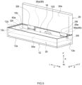
- FIG. 1 is a perspective view that schematically shows an electric storage device 1 in accordance with one embodiment.
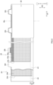
- FIG. 2 is a longitudinal cross section view that is schematically shown along a II-II line of FIG. 1 .
- FIG. 3 is a longitudinal cross section view that is schematically shown along a III-III line of FIG. 1 .
- the number of negative electrode tabs 24t is represented as 11, but the herein present disclosure is not restricted to this.
- reference signs L, R, F, Rr, U, and D in the figures respectively represent left, right, front, rear, up, and down (in a gravity direction).
- a reference sign X represents a short side direction (referred to as a thickness direction, too) of the electric storage device 1
- a reference sign Y represents a long side direction of the electric storage device 1
- a reference sign Z represents a vertically direction (referred to as a height direction, too).
- these are merely directions for convenience sake of explanation, which never restricts the disposed form of the electric storage device 1.
- the electric storage device 1 includes a case 10, an electrode body 20, a positive electrode terminal 30, and a negative electrode terminal 40. As the illustration is omitted, the electric storage device 1 herein further includes an electrolytic solution. It is preferable that the electric storage device 1 is a nonaqueous electrolyte secondary battery, such as lithium ion secondary battery.
- the case 10 is, for example, a member formed in a hexahedron shape and configured to accommodate the electrode body 20. As shown in FIG. 1 and FIG. 2 , the case 10 includes an exterior package 12 and a sealing plate 14. The case 10 is typically made of a metal, such as aluminum, aluminum alloy, and stainless steel.
- the exterior package 12 is, for example, a main body of the case 10 which is configured to accommodate the electrode body 20 at the inside.
- the exterior package 12 includes an opening 12h, a first surface 12a, a pair of opposed second surfaces 12b, 12c, and a pair of opposed third surfaces 12d, 12e.
- the first surface 12a is formed in a wide width rectangular shape, and is opposed to the opening 12h.
- a pair of second surfaces 12b, 12c respectively extend from a pair of opposed long sides of the first surface 12a.
- the second surface 12c which is positioned at a lower side, configures a bottom surface of the electric storage device 1.
- the second surface 12b which is positioned at an upper side, is an upper surface opposed to this bottom surface, and herein is an attaching surface with the positive electrode terminal 30 and the negative electrode terminal 40.
- a pair of third surfaces 12d, 12e respectively extend from a pair of opposed short sides of the first surface 12a.
- the term "rectangular shape” semantically covers a shape in which the long side formed in a straight line shape and a short side formed in a straight line shape are joined to each other via a curved line, a shape in which at least one of the long side and the short side is formed in a not-straight line shape but is bent, concaved and convexed, or curved so as to be configured with plural straight lines or with curved lines, and the like.
- the opening 12h is a portion, for example, on which the sealing plate 14 is attached.
- the opening 12h is surrounded by upper ends of the pair of second surfaces 12b, 12c and upper ends of the pair of third surfaces 12d, 12e, so as to be formed in a wide width rectangular shape.
- the opening 12h is provided with a recessed step 121 along an inner end.
- the sealing plate 14 is fit into the step 121.
- the exterior package 12 and the sealing plate 14 are integrated so as to make the case 10 be sealed airtightly.
- the second surface 12b is provided with an exhaust valve 123, a liquid injection hole 16, a first terminal attaching part 124, and a second terminal attaching part 125.
- the exhaust valve 123 is, for example, a thin-walled part.
- the exhaust valve 123 is configured to be broken when a pressure inside the case 10 becomes equal to or more than a predetermined value, so as to exhaust a gas inside the case 10 toward an outside.
- the liquid injection hole 16 is a penetration hole for performing a liquid injection of the electrolytic solution to the inside of the case 10 after the sealing plate 14 is assembled to the exterior package 12.
- the liquid injection hole 16 here is sealed by a sealing member 16a after the liquid injection of the electrolytic solution.
- the first terminal attaching part 124 is, for example, a portion to which the positive electrode terminal 30 is attached. On a form shown in FIG. 2 , the first terminal attaching part 124 is a step recessed from the second surface 12b. On a bottom of the first terminal attaching part 124, a penetration hole 18 is provided into which the positive electrode terminal 30 is inserted.
- the second terminal attaching part 125 is, for example, a portion to which the negative electrode terminal 40 is attached. On the form shown in FIG. 2 , the second terminal attaching part 125 is a step recessed from the second surface 12b. On a bottom of the second terminal attaching part 125, a penetration hole 19 is provided into which the negative electrode terminal 40 is inserted.
- the sealing plate 14 is, for example, a member formed in a flat plate shape and is configured to seal the opening 12h.
- a shape of the sealing plate 14 is a shape according to a shape of the opening 12h.
- the sealing plate 14 is formed in a wide width rectangular shape.
- the sealing plate 14 is opposed to the first surface 12a.
- a nonaqueous electrolytic solution is preferably used in which a supporting salt (electrolyte salt) is dissolved into a nonaqueous type solvent (organic solvent).
- a nonaqueous type solvent it is possible to use a carbonate type solvent, such as ethylene carbonate, dimethyl carbonate, and ethyl methyl carbonate.
- a fluorine-containing lithium salt such as LiPF 6 .
- the electrolytic solution may contain an additive agent as needed.
- the positive electrode terminal 30 is a member electrically connected to a positive electrode 22 of the electrode body 20. As shown in FIG. 2 , the positive electrode terminal 30 is inserted into the penetration hole 18 so as to be exposed to an outer side of the exterior package 12.
- the positive electrode terminal 30 includes a shaft part 30a and a base part 30b.
- the shaft part 30a is, for example, formed in a cylindrical shape and is a portion inserted into the penetration hole 18.
- the base part 30b is, for example, formed in a flat plate shape, and is a portion arranged along an outer side surface (the second surface 12b) of the exterior package 12. As shown in FIG.
- the positive electrode terminal 30 herein is caulked by a caulking process to a circumferential edge portion surrounding the penetration hole 18 of the exterior package 12, and a caulking part is formed inside the exterior package 12 at an end part of the shaft part 30a.
- the positive electrode terminal 30 is made of metal, and it is further preferable that the positive electrode terminal is made of, for example, aluminum or aluminum alloy.
- the positive electrode terminal 30 is an example for the herein disclosed "terminal".
- the negative electrode terminal 40 is a member electrically connected to a negative electrode 24 of the electrode body 20. As shown in FIG. 2 , the negative electrode terminal 40 is inserted into the penetration hole 19 so as to be exposed to the outer side of the exterior package 12.
- the negative electrode terminal 40 includes a shaft part 40a and a base part 40b.
- the shaft part 40a is, for example, formed in a cylindrical shape and is a portion inserted into the penetration hole 19.
- the base part 40b is, for example, formed in a flat plate shape, and is a portion arranged along the outer side surface (the second surface 12b) of the exterior package 12. As shown in FIG.
- the negative electrode terminal 40 herein is caulked by the caulking process to a circumferential edge portion surrounding the penetration hole 19 of the exterior package 12, and a caulking part is formed inside the exterior package 12 at an end part of the shaft part 40a.
- the negative electrode terminal 40 is made of metal, and it is more preferable that the negative electrode terminal is made of, for example, copper or copper alloy.
- the negative electrode terminal 40 is an example for the herein disclosed "terminal".
- Each of the positive electrode terminal 30 and the negative electrode terminal 40 is insulated from the exterior package 12 by a gasket 92 and an inside insulating member 93.
- the gasket 92 herein has a function of establishing an insulation of the exterior package 12 from the positive electrode terminal 30 and the negative electrode terminal 40, and additionally sealing (closing) the penetration holes 18, 19. It is good for the gasket 92 or the inside insulating member 93 to use a material superior to a chemical resistant property or a weather resistant property.
- the gasket 92 and the inside insulating member 93 may be configured with a resin material having an electrically insulating property and being able to be elastically deformed, for example, a fluorinated resin, such as perfluoroalkoxy fluorine resin (PFA), a polyphenylene sulfide resin (PPS), an aliphatic polyamide, or the like.
- a fluorinated resin such as perfluoroalkoxy fluorine resin (PFA), a polyphenylene sulfide resin (PPS), an aliphatic polyamide, or the like.
- PFA perfluoroalkoxy fluorine resin
- PPS polyphenylene sulfide resin
- aliphatic polyamide or the like.
- the electrode body 20 is, for example, a power generating element of the electric storage device 1 that includes the positive electrode 22 and the negative electrode 24.
- FIG. 4 is a schematic view of the electrode body 20 in accordance with one embodiment.
- the electrode body 20 is a wound electrode body in which the positive electrode 22 formed in a long sheet shape and the negative electrode 24 formed in a long sheet shape are wound in a sheet longitudinal direction LD via the separator 23.
- the electrode body 20 can be manufactured, for example, by winding the positive electrode 22, the negative electrode 24, and the separator 23 to be a cylindrical body and then to perform press molding on the cylindrical body.
- the electrode body 20 is formed in a flat shape, and has a pair of wide width surfaces 20a (see FIG. 2 and FIG. 3 ).
- a number of the electrode bodies 20 arranged inside one exterior package 12, which is not particularly restricted, may be equal to or more than two (plural), or may be one. As shown in FIG. 3 , herein, two electrode bodies are arranged inside the outer package 12.
- the electrode body 20 is accommodated in the exterior package 12 to make the winding axis direction WD and a vertical direction (an up and down direction) of the electric storage device 1 be approximately parallel.
- the winding axis WL of the electrode body 20 is approximately parallel to the first surface 12a, the third surfaces 12d, 12e, and the sealing plate 14, and is approximately perpendicular to the second surfaces 12b, 12c.
- the wide width surface 20a of the electrode body 20 is opposed to the first surface 12a and the sealing plate 14.
- one of end surfaces of the electrode body 20 is opposed to the second surface 12b and the other one of the end surfaces is opposed to the second surface 12c.
- the end surface of the electrode body 20 is a laminate surface of the positive electrode 22, the negative electrode 24, and the separator 23, and is a open surface.
- the electrode body 20 may be accommodated inside the case 10 under a state of being covered by an electrode body holder, which is not shown in figures and is configured with a resin sheet having an insulating property.
- the positive electrode 22 includes a positive electrode collecting foil 22c (for example, an aluminum foil) formed in a long strip-like shape and a positive electrode active material layer 22a fixed on at least one surface of the positive electrode collecting foil 22c.
- a positive electrode collecting foil 22c for example, an aluminum foil
- a positive electrode active material layer 22a fixed on at least one surface of the positive electrode collecting foil 22c.
- one of side edge parts of the positive electrode 22 in the winding axis direction WD may be, as needed, provided with a protective layer 22p.
- a configuration material of the positive electrode active material layer 22a and a configuration material of the protective layer 22p it is possible without particular restriction to use those utilized for this kind of electric storage device (a lithium ion secondary battery in this embodiment).
- One of end parts (a top end part of FIG. 4 ) of the positive electrode collecting foil 22c in the winding axis direction WD is provided with plural positive electrode tabs 22t.
- the plural positive electrode tabs 22t protrude toward said one of end parts (the top end part of FIG. 4 ) in the winding axis direction WD.
- the plural positive electrode tabs 22t are provided along the longitudinal direction LD of the positive electrode 22 at the intervals (intermittently).
- the positive electrode tab 22t is a part of the positive electrode collecting foil 22c and is a portion of the positive electrode collecting foil 22c where the positive electrode active material layer 22a is not formed (an active material layer unformed part). In the embodiment shown by FIG.
- a protective layer 22p is provided at a base end side of the positive electrode tab 22t.
- plural positive electrode tabs 22t protrude in the winding axis direction WD more than the separator 23.
- a shape and a size of the positive electrode tab 22t can be suitably adjusted, for example, in consideration of a state where it is connected to the positive electrode terminal 30, based on a formed position of it, or the like.
- Plural positive electrode tabs 22t are laminated at one of the end parts (the top end part of FIG. 4 ) in the winding axis direction WD, so as to configure a positive electrode tab group.
- each positive electrode tab 22t may not be the same.
- the positive electrode tab 22t is an example of the "tab" disclosed herein.
- the negative electrode 24 includes a negative electrode collecting foil 24c (for example, a copper foil) formed in a long strip-like shape, and a negative electrode active material layer 24a fixed on at least one surface of the negative electrode collecting foil 24c.
- a configuration material of the negative electrode active material layer 24a it is possible without particular restriction to use one utilized for this kind of electric storage device (the lithium ion secondary battery in this embodiment).
- plural negative electrode tabs 24t are provided.
- the plural negative electrode tabs 24t protrude to one of the end parts (the top end part of FIG. 4 ) in the winding axis direction WD.
- the plural negative electrode tabs 24t are provided along the longitudinal direction LD of the negative electrode 24 at the intervals (intermittently).
- the negative electrode tab 24t is a part of the negative electrode collecting foil 24c, and is a portion of the negative electrode collecting foil 24c where the negative electrode active material layer 24a is not formed (an active material layer unformed part).
- the plural negative electrode tabs 24t protrude in the winding axis direction WD more than the separator 23.
- a shape and a size of the negative electrode tab 24t can be suitably adjusted, for example, in consideration of a state where it is connected to the negative electrode terminal 40, based on a formed position of it, or the like.
- the plural negative electrode tabs 24t are laminated at one of the end parts (the top end part of FIG. 4 ) in the winding axis direction WD, so as to configure a negative electrode tab group.
- a height (a length in the winding axis direction WD) of each negative electrode tab 24t and a width (a length in the longitudinal direction LD) of each negative electrode tab 24t may not be the same.
- the positive electrode tab 22t is an example of the herein disclosed "tab".
- the separator 23 is a member establishing an insulation between the positive electrode active material layer 22a of the positive electrode 22 and the negative electrode active material layer 24a of the negative electrode 24.
- the separator 23 in this embodiment configures an outer surface of the electrode body 20.
- a porous sheet made of resin consisting of polyolefin resin, such as polyethylene (PE) and polypropylene (PP).
- a lower end P3 of the separator 23 is positioned at the lowest side, then a lower end P2 of the negative electrode 24 is positioned, and a lower end P1 of the positive electrode 22 is positioned at the uppermost side.
- widths of respective sheets a length in the winding axis direction WD of FIG. 4 , however, excluding the positive electrode tab 22t and the negative electrode tab 24t), they are larger in an order of the separator 23, the negative electrode 24, and the positive electrode 22.
- the electrode body 20 includes the wide width surface 20a opposed to the sealing plate 14 and the first surface 12a. Further, it is arranged inside the case 10 to make the positive electrode tab 22t and the negative electrode tab 24t be opposed to the second surface 12b on which the positive electrode terminal 30 and the negative electrode terminal 40 are attached. Then, the positive electrode tab 22t is joined to the positive electrode terminal 30 (specifically, the shaft part 30a) by a metal joint 50. Similarly, the negative electrode tab 24t is joined to the negative electrode terminal 40 (specifically, the shaft part 40a) by the metal joint 50.
- the metal joint 50 is, for example, a portion where a tab and a terminal (here, the positive electrode tab 22t and positive electrode terminal 30, and the negative electrode tab 24t and negative electrode terminal 40) are melted and solidified so as to be joined mutually.
- the exterior package 12 used in the herein disclosed electric storage device 1 includes an opening 12h formed in a wide-width rectangular shape.
- the metal joint 50 can be, for example, suitably formed by laser welding, ultrasonic joining, resistance welding, or the like.
- the exterior package 12 includes the opening 12h formed in the wide-width rectangular shape, ant thus it is possible to easily accommodate the electrode body 20 inside the exterior package 12. Accordingly, in comparison to the electric storage device in which the conventional case is used (see Patent Document 1), it is possible to make a clearance, required for accommodating the electrode body 20, be smaller. By doing this, it is possible to further make a volume of the electrode body 20 be larger. In addition, by increasing the volume of the electrode body 20, a movable range of the electrode body 20 in the case 10 is reduced. By doing this, it is possible to suitably reduce breakage risks of the positive electrode tab 22t and the negative electrode tab 24t. Accordingly, it is possible to compatibly implement an enhancement of the capacity (a high volume energy density) and a conduction reliability of the electric storage device 1.
- plural electrode bodies 20 are arranged inside the case 10 (the exterior package 12), and the metal joint 50 is formed by joining the positive electrode tabs 22t and the negative electrode tabs 24t of plural electrode bodies 20, and the positive electrode terminal 30 and the negative electrode terminal 40.
- the electric storage device 1 of the present embodiment includes two electrode bodies 20, to which the herein present disclosure is not restricted, and may include three or more electrode bodies 20.
- the sealing plate 14 and a surface opposed to the sealing plate 14 within the wide-width surface 20a of the electrode body 20 are abutted.
- it is configured to make the wide width surface 20a of the electrode body 20 be pushed by the sealing plate 14, when the electrode body 20 is accommodated and the sealing plate 14 and the exterior package 12 are welded.
- a movement of the electrode body 20 inside the case 10 is regulated even in a situation where a vibration, an impact, or the like are applied at the time when the electric storage device 1 is used.
- the electric storage device 1 when the electric storage device 1 is formed in the aspect described above, it is preferable that, for example, among the wide width surface 20a of the electrode body 20, approximately 70% or more is abutted on the sealing plate 14, or approximately 80% or more is abutted on the sealing plate 14.
- the electric storage device 1 can be manufactured by preparing the case 10 as described above (the exterior package 12 and the sealing plate 14), the electrode body 20 (one or plural, herein two), the electrolytic solution, the positive electrode terminal 30, and the negative electrode terminal 40, and by using a manufacturing method, for example, which includes a terminal assembling step, an electrode body accommodating step, a metal joint forming step, a sealing-plate sealing step, and a liquid injection step, typically in this order.
- the manufacturing method of the electric storage device 1 is characterized by using the case 10 and the electrode body 20 which are as described above, and then by performing the electrode body accommodating step, the metal joint forming step, and the sealing step.
- the other manufacture processes may be similar to conventional manufacture processes.
- the herein disclosed manufacturing method may further include a different step at an arbitrary stage.
- the positive electrode terminal 30, the negative electrode terminal 40, the gasket 92, and the inside insulating member 93 are assembled on the second surface 12b of the exterior package 12.
- the negative electrode terminal 40 can be fixed on the second surface 12b of the exterior package 12, for example, by a caulking process (riveting). The caulking process is performed, while the gasket 92 is sandwiched between the negative electrode terminal 40 and the second surface 12b of the exterior package 12 and further the insulating member 80 is sandwiched between the second surface 12b of the exterior package 12 and the shaft part 40a of the negative electrode terminal 40 (see FIG. 8). By doing this, an end part of the shaft part 40a of the negative electrode terminal 40 is caulked.
- the gasket 92 and the inside insulating member 93 are compressed, the negative electrode terminal 40, the second surface 12b of the exterior package 12, and the inside insulating member 93 are integrally fixed on the second surface 12b of the exterior package 12, and additionally the penetration hole 19 is sealed.
- an assembling method for the positive electrode terminal 30 side may be similar to the assembling method for the negative electrode terminal 40 side described above.
- the terminal assembling step is not restricted to this, and thus, for example, the second surface 12b of the exterior package 12, the positive electrode terminal 30, and the negative electrode terminal 40, and the gasket 92 and the inside insulating member 93 may be integrated by an insertion molding.
- FIG. 5 is a schematic view that is to explain the electrode body accommodating step and the tab joining step in accordance with one embodiment.
- a join planned part 50a (a formation planned part of the metal joint 50) is represented by an imaginary line.
- the electrode body 20 is arranged to make one of the wide width surfaces 20a of the electrode body 20 be opposed to the first surface 12a and to make the positive electrode tab 22t and the negative electrode tab 24t be opposed to the second surface 12b to which the positive electrode terminal 30 and the negative electrode terminal 40 are attached.
- the positive electrode tab 22t is bent and is arranged to be opposed to the shaft part 30a of the positive electrode terminal 30.
- the negative electrode tab 24t is bent and is arranged to be opposed to the shaft part 40a of the negative electrode terminal 40.
- the electrode body accommodating step is firstly performed for one electrode body 20 among two electrode bodies 20. Then, after the tab joining step, the electrode body accommodating step is performed for the remaining one of the electrode bodies 20.
- the plural positive electrode tabs 22t and the positive electrode terminal 30, and the plural negative electrode tabs 24t and the negative electrode terminal 40 are electrically joined.
- a joining method by laser welding is explained as an example, but the herein present disclosure is not restricted to this, and thus, for example, the above described joining method may be used.
- arrangement is performed to make the negative electrode tab 24t of the electrode body 20 be stacked on the shaft part 40a of the negative electrode terminal 40.
- the negative electrode tab 24t may be folded and bent in order to make the shaft part 40a of the negative electrode terminal 40 be easily stacked.
- the electric storage device 1 includes the plural electrode bodies 20, as shown in FIG. 3 and FIG.
- the negative electrode tab 24t of the other electrode body 20 may be further stacked on the negative electrode tab 24t of one electrode body 20. Then, in a state where the negative electrode tab 24t is stacked on the shaft part 40a of the negative electrode terminal 40, a laser is used to scan on the join planned part 50a. By doing this, the metal joint 50 is formed, and the negative electrode terminal 40 and the negative electrode tab 24t are electrically connected.
- a joining method for the positive electrode tab 22t and the positive electrode terminal 30 may be similar to the above described joining method for the negative electrode tab 24t and the negative electrode terminal 40. Additionally, in FIG.
- the third surface 12e of the exterior package 12 is positioned at the lower side for convenience sake of explanation, but the herein present disclosure is not restricted to this.
- the tab joining step based on the joining method or a jig used for joining, it is possible to perform the tab joining step in a state where the exterior package 12 is tilted by an angle at which it is easy to form the metal joint 50.
- FIG. 6 is a schematic view that is to explain the sealing-plate sealing step in accordance with one practical example.
- a press direction of the sealing plate 14 is represented by a white arrow and a scanning path of a laser L is represented by an imaginary line.
- the sealing plate 14, in which to the opening 12h of the exterior package 12 the sealing plate 14 is fit, is pushed into a first surface 12a direction (a white arrow direction of FIG. 6 ) of the exterior package 12.
- the sealing plate 14 and the exterior package 12 are sealed.
- the opening 12h of the exterior package 12 is sealed with the sealing plate 14. Accordingly, it is possible to further suitably reduce damage risks of the positive electrode tab 22t and the negative electrode tab 24t.
- the laser L is allowed to scan.
- the sealing method is not restricted to this.
- a press strength of the sealing plate 14 is not particularly restricted, can be changed suitably based on a material, a thickness, or a size of the case 10.
- the press strength of the sealing plate 14 may be equal to or more than 10 kN.
- the electrolytic solution is injected to the inside of the case 10 from the liquid injection hole 16. Then, the liquid injection hole 16 is covered by the sealing member 16a so as to hermetically seal the case 10. Thus, it is possible to manufacture the electric storage device 1.
- the electric storage device 1 can be used for various purposes, it can be suitably used for a purpose in which increasing a capacity of the electric storage device 1 is required, or a purpose in which an external force, such as vibration and impact, may be applied at the use time, typically as a power source (power supply for driving) for a motor mounted on various vehicles, for example, a passenger car, a truck, or the like.
- a power source power supply for driving
- the kind of the vehicle is not particularly restricted, but it is possible to use it, for example, on a plug-in hybrid electric vehicle (PHEV), a hybrid electric vehicle (HEV), a battery electric vehicle (BEV), or the like.
- Item 1 An electric storage device, comprising:
- Item 2 The electric storage device recited in item 1, wherein
- Item 3 The electric storage device recited in item 1 or 2, wherein it is configured that the wide width surface of the electrode body is pushed by the sealing plate when the sealing plate and the exterior package are welded.
Landscapes
- Chemical & Material Sciences (AREA)
- Chemical Kinetics & Catalysis (AREA)
- Electrochemistry (AREA)
- General Chemical & Material Sciences (AREA)
- Engineering & Computer Science (AREA)
- Manufacturing & Machinery (AREA)
- Power Engineering (AREA)
- Microelectronics & Electronic Packaging (AREA)
- Materials Engineering (AREA)
- Connection Of Batteries Or Terminals (AREA)
- Sealing Battery Cases Or Jackets (AREA)
- Electric Double-Layer Capacitors Or The Like (AREA)
Abstract
An electric storage device is provided in which an enhancement of a space efficiency and an increase suppression of an electric resistance are compatibly implemented. The electric storage device of the present disclosure includes a case including an exterior package having a first surface formed in a wide width rectangular shape, having a pair of opposed second surfaces, having a pair of opposed third surfaces, and having an opening, and including a sealing plate configured to seal the opening and formed in a wide width rectangular shape. A positive electrode and a negative electrode include plural tabs protruding at one of end parts in a winding axis direction of the electrode body, and include a penetration hole at one surface of the second surface, a terminal is inserted into a penetration hole, wide width surfaces of the electrode body respectively face to the sealing plate and to the first surface, the tab is arranged inside the case to face to the second surface, and a metal
joint configured to connect the terminal and the tab is provided.
joint configured to connect the terminal and the tab is provided.
Description
- The present disclosure relates to an electric storage device.
- Conventionally, the electric storage device is known that includes an electrode body having a pair of opposed wide width surfaces, includes a case configured to accommodate the electrode body, and includes a terminal electrically connected to the electrode body. For example,
Japanese Patent Publication 2022-44958 - Based on an intensive study of the inventor, there is a room for improvement in the above described conventional technique. As described in detail, the above described electric storage device includes the electrical collector terminal (below, referred to as "electrical collector body", too), and thus a number of parts is increased so as to cause an increase in an electric resistance.
- A herein present disclosure has been made in view of the above-described circumstances, and the object is to provide an electric storage device that can compatibly implement enhancing the space efficiency and suppressing the increase in the electric resistance.
- A herein disclosed electric storage device includes an electrode body in which a long sheet-shaped positive electrode and a long sheet-shaped negative electrode are wound in a sheet longitudinal direction via a separator and which has a pair of opposed wide width surfaces, includes a case which is formed in a hexahedron shape, which is configured to accommodate the electrode body, and which has an exterior package having a first surface formed in a wide width rectangular shape, an opening opposed to the first surface, a pair of opposed second surfaces extending from an outer edge of the first surface to the opening, a pair of opposed third surfaces extending from the outer edge of the first surface to the opening, and has a sealing plate configured to seal the opening, opposed to the first surface, and formed in a wide width rectangular shape, and includes terminals electrically connected to the electrode body. Here, each of the positive electrode and the negative electrode includes plural tabs protruding at one of end parts in a winding axis direction of the electrode body, penetration holes are provided on one of the second surfaces, the terminals are inserted into the penetration holes, the electrode body is arranged inside the case, wherein the wide width surfaces respectively face the sealing plate and the first surface, and to make the tabs face the second surfaces to which the terminals are attached, and a metal joint is provided to connect the terminals and the tabs.
- According to the configuration described above, the tab of the electrode body and the terminal are directly and electrically connected by the metal joint without an electrical collector body, and thus it is possible to suppress the increase in the electric resistance. Further, by using the case configured as described above, it is possible to easily accommodate the electrode body in the case. By doing this, it is possible to further increase a volume of the electrode body. By increasing the volume of the electrode body, a movable range of the electrode body in the case is reduced. By doing this, it is possible to suitably reduce the breakage risk on the tab. Accordingly, it is possible to compatibly implement the capacity enhancement of the electric storage device (high volume energy density) and the conduction reliability.
-
-
FIG. 1 is a perspective view that schematically shows an electric storage device in accordance with one embodiment. -
FIG. 2 is a longitudinal cross section view that is schematically shown along a II-II line ofFIG. 1 . -
FIG. 3 is a longitudinal cross section view that is schematically shown along a III-III line ofFIG. 1 . -
FIG. 4 is a schematic view of an electrode body in accordance with one embodiment. -
FIG. 5 is a schematic view that is to explain an electrode body accommodating step and a tab joining step in accordance with one embodiment. -
FIG. 6 is a schematic view that is to explain a sealing-plate sealing step in accordance with one practical example. - Below, while referring to figures, an embodiment in accordance with a herein present disclosure will be explained. Incidentally, a matter not described in the present specification but required for performing the herein present disclosure can be grasped as design matters of those skilled in the art based on the related art in the present field. The herein present disclosure can be executed based on the contents disclosed in the present specification, and the technical common sense in the present field. Additionally, in the following accompanying figures, the same numerals and signs are given to the members/parts providing the same effect. Additionally, in each figure, the dimensional relation (a length, a width, a thickness, or the like) may not reflect the actual dimensional relation. Incidentally, a numerical value range expressed as "A to B" in the present specification semantically includes A and B, and semantically covers meanings of "preferably more than A" and "preferably less than B".
- A term "electric storage device" in the present specification means a device that can perform charging and discharging. The electric storage device semantically covers a battery referred to generally as a lithium ion battery, a lithium secondary battery, or the like, and further covers a lithium polymer battery, a lithium ion capacitor, and the like. The secondary battery means a battery in general that is capable of repeatedly charging and discharging according to a movement of a charge carrier between a positive electrode and a negative electrode. Here, as one form of the electric storage device, a lithium ion secondary battery is illustrated.
-
FIG. 1 is a perspective view that schematically shows anelectric storage device 1 in accordance with one embodiment.FIG. 2 is a longitudinal cross section view that is schematically shown along a II-II line ofFIG. 1 .FIG. 3 is a longitudinal cross section view that is schematically shown along a III-III line ofFIG. 1 . InFIG. 3 , for convenience sake of explanation, the number ofnegative electrode tabs 24t is represented as 11, but the herein present disclosure is not restricted to this. Incidentally, in an explanation described below, reference signs L, R, F, Rr, U, and D in the figures respectively represent left, right, front, rear, up, and down (in a gravity direction). Additionally, in the figures, a reference sign X represents a short side direction (referred to as a thickness direction, too) of theelectric storage device 1, a reference sign Y represents a long side direction of theelectric storage device 1, and a reference sign Z represents a vertically direction (referred to as a height direction, too). However, these are merely directions for convenience sake of explanation, which never restricts the disposed form of theelectric storage device 1. - As shown in
FIG. 1 andFIG. 2 , theelectric storage device 1 includes acase 10, anelectrode body 20, apositive electrode terminal 30, and anegative electrode terminal 40. As the illustration is omitted, theelectric storage device 1 herein further includes an electrolytic solution. It is preferable that theelectric storage device 1 is a nonaqueous electrolyte secondary battery, such as lithium ion secondary battery. - The
case 10 is, for example, a member formed in a hexahedron shape and configured to accommodate theelectrode body 20. As shown inFIG. 1 andFIG. 2 , thecase 10 includes anexterior package 12 and asealing plate 14. Thecase 10 is typically made of a metal, such as aluminum, aluminum alloy, and stainless steel. - The
exterior package 12 is, for example, a main body of thecase 10 which is configured to accommodate theelectrode body 20 at the inside. As shown inFIG. 1 andFIG. 2 , theexterior package 12 includes anopening 12h, afirst surface 12a, a pair of opposedsecond surfaces third surfaces first surface 12a is formed in a wide width rectangular shape, and is opposed to the opening 12h. In addition, a pair ofsecond surfaces first surface 12a. As shown inFIG. 1 andFIG. 2 , thesecond surface 12c, which is positioned at a lower side, configures a bottom surface of theelectric storage device 1. In addition, thesecond surface 12b, which is positioned at an upper side, is an upper surface opposed to this bottom surface, and herein is an attaching surface with thepositive electrode terminal 30 and thenegative electrode terminal 40. In addition, a pair ofthird surfaces first surface 12a. Incidentally, in the present specification, the term "rectangular shape" semantically covers a shape in which the long side formed in a straight line shape and a short side formed in a straight line shape are joined to each other via a curved line, a shape in which at least one of the long side and the short side is formed in a not-straight line shape but is bent, concaved and convexed, or curved so as to be configured with plural straight lines or with curved lines, and the like. - The opening 12h is a portion, for example, on which the
sealing plate 14 is attached. Here, the opening 12h is surrounded by upper ends of the pair ofsecond surfaces third surfaces FIG. 3 , the opening 12h is provided with arecessed step 121 along an inner end. Here, thesealing plate 14 is fit into thestep 121. In addition, by welding thesealing plate 14 to thestep 121 of theexterior package 12, theexterior package 12 and thesealing plate 14 are integrated so as to make thecase 10 be sealed airtightly. - As shown in
FIG. 2 , thesecond surface 12b is provided with anexhaust valve 123, aliquid injection hole 16, a firstterminal attaching part 124, and a secondterminal attaching part 125. Theexhaust valve 123 is, for example, a thin-walled part. Here, theexhaust valve 123 is configured to be broken when a pressure inside thecase 10 becomes equal to or more than a predetermined value, so as to exhaust a gas inside thecase 10 toward an outside. Theliquid injection hole 16 is a penetration hole for performing a liquid injection of the electrolytic solution to the inside of thecase 10 after the sealingplate 14 is assembled to theexterior package 12. Theliquid injection hole 16 here is sealed by a sealingmember 16a after the liquid injection of the electrolytic solution. The firstterminal attaching part 124 is, for example, a portion to which thepositive electrode terminal 30 is attached. On a form shown inFIG. 2 , the firstterminal attaching part 124 is a step recessed from thesecond surface 12b. On a bottom of the firstterminal attaching part 124, apenetration hole 18 is provided into which thepositive electrode terminal 30 is inserted. The secondterminal attaching part 125 is, for example, a portion to which thenegative electrode terminal 40 is attached. On the form shown inFIG. 2 , the secondterminal attaching part 125 is a step recessed from thesecond surface 12b. On a bottom of the secondterminal attaching part 125, apenetration hole 19 is provided into which thenegative electrode terminal 40 is inserted. - The sealing
plate 14 is, for example, a member formed in a flat plate shape and is configured to seal theopening 12h. Thus, it is good that a shape of the sealingplate 14 is a shape according to a shape of theopening 12h. In this embodiment, the sealingplate 14 is formed in a wide width rectangular shape. Here, when the sealingplate 14 is attached to theopening 12h, the sealingplate 14 is opposed to thefirst surface 12a. - As the electrolytic solution, it is possible to use conventionally known one without particular restriction. As one example, a nonaqueous electrolytic solution is preferably used in which a supporting salt (electrolyte salt) is dissolved into a nonaqueous type solvent (organic solvent). As one example of the nonaqueous type solvent, it is possible to use a carbonate type solvent, such as ethylene carbonate, dimethyl carbonate, and ethyl methyl carbonate. As one example of the supporting salt, it is possible to use a fluorine-containing lithium salt, such as LiPF6. The electrolytic solution may contain an additive agent as needed.
- The
positive electrode terminal 30 is a member electrically connected to a positive electrode 22 of theelectrode body 20. As shown inFIG. 2 , thepositive electrode terminal 30 is inserted into thepenetration hole 18 so as to be exposed to an outer side of theexterior package 12. Here, thepositive electrode terminal 30 includes ashaft part 30a and abase part 30b. Theshaft part 30a is, for example, formed in a cylindrical shape and is a portion inserted into thepenetration hole 18. Thebase part 30b is, for example, formed in a flat plate shape, and is a portion arranged along an outer side surface (thesecond surface 12b) of theexterior package 12. As shown inFIG. 2 , thepositive electrode terminal 30 herein is caulked by a caulking process to a circumferential edge portion surrounding thepenetration hole 18 of theexterior package 12, and a caulking part is formed inside theexterior package 12 at an end part of theshaft part 30a. It is preferable that thepositive electrode terminal 30 is made of metal, and it is further preferable that the positive electrode terminal is made of, for example, aluminum or aluminum alloy. Incidentally, thepositive electrode terminal 30 is an example for the herein disclosed "terminal". - The
negative electrode terminal 40 is a member electrically connected to anegative electrode 24 of theelectrode body 20. As shown inFIG. 2 , thenegative electrode terminal 40 is inserted into thepenetration hole 19 so as to be exposed to the outer side of theexterior package 12. Here, thenegative electrode terminal 40 includes ashaft part 40a and abase part 40b. Theshaft part 40a is, for example, formed in a cylindrical shape and is a portion inserted into thepenetration hole 19. Thebase part 40b is, for example, formed in a flat plate shape, and is a portion arranged along the outer side surface (thesecond surface 12b) of theexterior package 12. As shown inFIG. 2 , thenegative electrode terminal 40 herein is caulked by the caulking process to a circumferential edge portion surrounding thepenetration hole 19 of theexterior package 12, and a caulking part is formed inside theexterior package 12 at an end part of theshaft part 40a. It is preferable that thenegative electrode terminal 40 is made of metal, and it is more preferable that the negative electrode terminal is made of, for example, copper or copper alloy. Incidentally, thenegative electrode terminal 40 is an example for the herein disclosed "terminal". - Each of the
positive electrode terminal 30 and thenegative electrode terminal 40 is insulated from theexterior package 12 by agasket 92 and an inside insulatingmember 93. Thegasket 92 herein has a function of establishing an insulation of theexterior package 12 from thepositive electrode terminal 30 and thenegative electrode terminal 40, and additionally sealing (closing) the penetration holes 18, 19. It is good for thegasket 92 or the inside insulatingmember 93 to use a material superior to a chemical resistant property or a weather resistant property. Thegasket 92 and the inside insulatingmember 93 may be configured with a resin material having an electrically insulating property and being able to be elastically deformed, for example, a fluorinated resin, such as perfluoroalkoxy fluorine resin (PFA), a polyphenylene sulfide resin (PPS), an aliphatic polyamide, or the like. Thegasket 92 and the inside insulatingmember 93 may be, for example, integrated by insertion molding. - The
electrode body 20 is, for example, a power generating element of theelectric storage device 1 that includes the positive electrode 22 and thenegative electrode 24.FIG. 4 is a schematic view of theelectrode body 20 in accordance with one embodiment. As shown inFIG. 4 , theelectrode body 20 is a wound electrode body in which the positive electrode 22 formed in a long sheet shape and thenegative electrode 24 formed in a long sheet shape are wound in a sheet longitudinal direction LD via theseparator 23. Theelectrode body 20 can be manufactured, for example, by winding the positive electrode 22, thenegative electrode 24, and theseparator 23 to be a cylindrical body and then to perform press molding on the cylindrical body. Thus, theelectrode body 20 is formed in a flat shape, and has a pair ofwide width surfaces 20a (seeFIG. 2 andFIG. 3 ). A number of theelectrode bodies 20 arranged inside oneexterior package 12, which is not particularly restricted, may be equal to or more than two (plural), or may be one. As shown inFIG. 3 , herein, two electrode bodies are arranged inside theouter package 12. - As shown in
FIG. 2 andFIG. 3 , theelectrode body 20 is accommodated in theexterior package 12 to make the winding axis direction WD and a vertical direction (an up and down direction) of theelectric storage device 1 be approximately parallel. In this embodiment, the winding axis WL of theelectrode body 20 is approximately parallel to thefirst surface 12a, thethird surfaces plate 14, and is approximately perpendicular to thesecond surfaces wide width surface 20a of theelectrode body 20 is opposed to thefirst surface 12a and the sealingplate 14. In addition, one of end surfaces of theelectrode body 20 is opposed to thesecond surface 12b and the other one of the end surfaces is opposed to thesecond surface 12c. The end surface of theelectrode body 20 is a laminate surface of the positive electrode 22, thenegative electrode 24, and theseparator 23, and is a open surface. Incidentally, theelectrode body 20 may be accommodated inside thecase 10 under a state of being covered by an electrode body holder, which is not shown in figures and is configured with a resin sheet having an insulating property. - As shown in
FIG. 4 , the positive electrode 22 includes a positiveelectrode collecting foil 22c (for example, an aluminum foil) formed in a long strip-like shape and a positive electrodeactive material layer 22a fixed on at least one surface of the positiveelectrode collecting foil 22c. Although not particularly restricting, one of side edge parts of the positive electrode 22 in the winding axis direction WD may be, as needed, provided with aprotective layer 22p. Incidentally, as a configuration material of the positive electrodeactive material layer 22a and a configuration material of theprotective layer 22p, it is possible without particular restriction to use those utilized for this kind of electric storage device (a lithium ion secondary battery in this embodiment). - One of end parts (a top end part of
FIG. 4 ) of the positiveelectrode collecting foil 22c in the winding axis direction WD is provided with pluralpositive electrode tabs 22t. The pluralpositive electrode tabs 22t protrude toward said one of end parts (the top end part ofFIG. 4 ) in the winding axis direction WD. The pluralpositive electrode tabs 22t are provided along the longitudinal direction LD of the positive electrode 22 at the intervals (intermittently). Thepositive electrode tab 22t is a part of the positiveelectrode collecting foil 22c and is a portion of the positiveelectrode collecting foil 22c where the positive electrodeactive material layer 22a is not formed (an active material layer unformed part). In the embodiment shown byFIG. 4 , aprotective layer 22p is provided at a base end side of thepositive electrode tab 22t. In this embodiment, pluralpositive electrode tabs 22t protrude in the winding axis direction WD more than theseparator 23. A shape and a size of thepositive electrode tab 22t can be suitably adjusted, for example, in consideration of a state where it is connected to thepositive electrode terminal 30, based on a formed position of it, or the like. Pluralpositive electrode tabs 22t are laminated at one of the end parts (the top end part ofFIG. 4 ) in the winding axis direction WD, so as to configure a positive electrode tab group. Thus, a height (a length in the winding axis direction WD) of eachpositive electrode tab 22t and a width (a length in the longitudinal direction LD) of eachpositive electrode tab 22t may not be the same. Thepositive electrode tab 22t is an example of the "tab" disclosed herein. - As shown in
FIG. 4 , thenegative electrode 24 includes a negativeelectrode collecting foil 24c (for example, a copper foil) formed in a long strip-like shape, and a negative electrodeactive material layer 24a fixed on at least one surface of the negativeelectrode collecting foil 24c. Incidentally, as a configuration material of the negative electrodeactive material layer 24a, it is possible without particular restriction to use one utilized for this kind of electric storage device (the lithium ion secondary battery in this embodiment). - At one of the end parts (the top end part of
FIG. 4 ) of the negativeelectrode collecting foil 24c in the winding axis direction WD, pluralnegative electrode tabs 24t are provided. The pluralnegative electrode tabs 24t protrude to one of the end parts (the top end part ofFIG. 4 ) in the winding axis direction WD. The pluralnegative electrode tabs 24t are provided along the longitudinal direction LD of thenegative electrode 24 at the intervals (intermittently). Thenegative electrode tab 24t is a part of the negativeelectrode collecting foil 24c, and is a portion of the negativeelectrode collecting foil 24c where the negative electrodeactive material layer 24a is not formed (an active material layer unformed part). In this embodiment, the pluralnegative electrode tabs 24t protrude in the winding axis direction WD more than theseparator 23. A shape and a size of thenegative electrode tab 24t can be suitably adjusted, for example, in consideration of a state where it is connected to thenegative electrode terminal 40, based on a formed position of it, or the like. For example, the pluralnegative electrode tabs 24t are laminated at one of the end parts (the top end part ofFIG. 4 ) in the winding axis direction WD, so as to configure a negative electrode tab group. Thus, a height (a length in the winding axis direction WD) of eachnegative electrode tab 24t and a width (a length in the longitudinal direction LD) of eachnegative electrode tab 24t may not be the same. Thepositive electrode tab 22t is an example of the herein disclosed "tab". - The
separator 23 is a member establishing an insulation between the positive electrodeactive material layer 22a of the positive electrode 22 and the negative electrodeactive material layer 24a of thenegative electrode 24. Theseparator 23 in this embodiment configures an outer surface of theelectrode body 20. As theseparator 23, it is possible to use, for example, a porous sheet made of resin consisting of polyolefin resin, such as polyethylene (PE) and polypropylene (PP). - As shown in
FIG. 4 , regarding theelectrode body 20, a lower end P3 of theseparator 23 is positioned at the lowest side, then a lower end P2 of thenegative electrode 24 is positioned, and a lower end P1 of the positive electrode 22 is positioned at the uppermost side. Regarding widths of respective sheets (a length in the winding axis direction WD ofFIG. 4 , however, excluding thepositive electrode tab 22t and thenegative electrode tab 24t), they are larger in an order of theseparator 23, thenegative electrode 24, and the positive electrode 22. - In the herein disclosed
electric storage device 1, theelectrode body 20 includes thewide width surface 20a opposed to the sealingplate 14 and thefirst surface 12a. Further, it is arranged inside thecase 10 to make thepositive electrode tab 22t and thenegative electrode tab 24t be opposed to thesecond surface 12b on which thepositive electrode terminal 30 and thenegative electrode terminal 40 are attached. Then, thepositive electrode tab 22t is joined to the positive electrode terminal 30 (specifically, theshaft part 30a) by ametal joint 50. Similarly, thenegative electrode tab 24t is joined to the negative electrode terminal 40 (specifically, theshaft part 40a) by themetal joint 50. The metal joint 50 is, for example, a portion where a tab and a terminal (here, thepositive electrode tab 22t andpositive electrode terminal 30, and thenegative electrode tab 24t and negative electrode terminal 40) are melted and solidified so as to be joined mutually. - The
exterior package 12 used in the herein disclosedelectric storage device 1 includes anopening 12h formed in a wide-width rectangular shape. Thus, not only thepositive electrode tab 22t and thepositive electrode terminal 30, but also thenegative electrode tab 24t and thenegative electrode terminal 40 can be electrically connected, without the electrical collector body, by themetal joint 50. In other words, theelectrode body 20 and thepositive electrode terminal 30, and it and thenegative electrode terminal 40 are directly and electrically connected. Accordingly, it is possible to suppress an increase in the electric resistance of theelectric storage device 1. The metal joint 50 can be, for example, suitably formed by laser welding, ultrasonic joining, resistance welding, or the like. - The
exterior package 12 includes theopening 12h formed in the wide-width rectangular shape, ant thus it is possible to easily accommodate theelectrode body 20 inside theexterior package 12. Accordingly, in comparison to the electric storage device in which the conventional case is used (see Patent Document 1), it is possible to make a clearance, required for accommodating theelectrode body 20, be smaller. By doing this, it is possible to further make a volume of theelectrode body 20 be larger. In addition, by increasing the volume of theelectrode body 20, a movable range of theelectrode body 20 in thecase 10 is reduced. By doing this, it is possible to suitably reduce breakage risks of thepositive electrode tab 22t and thenegative electrode tab 24t. Accordingly, it is possible to compatibly implement an enhancement of the capacity (a high volume energy density) and a conduction reliability of theelectric storage device 1. - In some preferable aspects, as shown in
FIG. 3 ,plural electrode bodies 20 are arranged inside the case 10 (the exterior package 12), and the metal joint 50 is formed by joining thepositive electrode tabs 22t and thenegative electrode tabs 24t ofplural electrode bodies 20, and thepositive electrode terminal 30 and thenegative electrode terminal 40. According to a configuration described above, it is possible to implement providing theelectric storage device 1 whose capacity is further suitably enhanced. Incidentally, theelectric storage device 1 of the present embodiment includes twoelectrode bodies 20, to which the herein present disclosure is not restricted, and may include three ormore electrode bodies 20. - In some preferable aspects, inside the
case 10, the sealingplate 14 and a surface opposed to the sealingplate 14 within the wide-width surface 20a of the electrode body 20 (thewide width surface 20a of theelectrode body 20 opposed to the sealingplate 14, whenplural electrode bodies 20 are accommodated in the case 10) are abutted. In other words, it is configured to make thewide width surface 20a of theelectrode body 20 be pushed by the sealingplate 14, when theelectrode body 20 is accommodated and the sealingplate 14 and theexterior package 12 are welded. According to the configuration described above, a movement of theelectrode body 20 inside thecase 10 is regulated even in a situation where a vibration, an impact, or the like are applied at the time when theelectric storage device 1 is used. By doing this, it is possible to further suitably reduce the damage risks of thepositive electrode tab 22t and thenegative electrode tab 24t. Accordingly, it is possible to provide theelectric storage device 1 whose conduction reliability is further enhanced. Incidentally, when theelectric storage device 1 is formed in the aspect described above, it is preferable that, for example, among thewide width surface 20a of theelectrode body 20, approximately 70% or more is abutted on the sealingplate 14, or approximately 80% or more is abutted on the sealingplate 14. - The
electric storage device 1 can be manufactured by preparing thecase 10 as described above (theexterior package 12 and the sealing plate 14), the electrode body 20 (one or plural, herein two), the electrolytic solution, thepositive electrode terminal 30, and thenegative electrode terminal 40, and by using a manufacturing method, for example, which includes a terminal assembling step, an electrode body accommodating step, a metal joint forming step, a sealing-plate sealing step, and a liquid injection step, typically in this order. The manufacturing method of theelectric storage device 1 is characterized by using thecase 10 and theelectrode body 20 which are as described above, and then by performing the electrode body accommodating step, the metal joint forming step, and the sealing step. The other manufacture processes may be similar to conventional manufacture processes. In addition, the herein disclosed manufacturing method may further include a different step at an arbitrary stage. - At the terminal assembling step, the
positive electrode terminal 30, thenegative electrode terminal 40, thegasket 92, and the inside insulatingmember 93 are assembled on thesecond surface 12b of theexterior package 12. Thenegative electrode terminal 40 can be fixed on thesecond surface 12b of theexterior package 12, for example, by a caulking process (riveting). The caulking process is performed, while thegasket 92 is sandwiched between thenegative electrode terminal 40 and thesecond surface 12b of theexterior package 12 and further the insulating member 80 is sandwiched between thesecond surface 12b of theexterior package 12 and theshaft part 40a of the negative electrode terminal 40 (see FIG. 8). By doing this, an end part of theshaft part 40a of thenegative electrode terminal 40 is caulked. By the caulking process as described above, thegasket 92 and the inside insulatingmember 93 are compressed, thenegative electrode terminal 40, thesecond surface 12b of theexterior package 12, and the inside insulatingmember 93 are integrally fixed on thesecond surface 12b of theexterior package 12, and additionally thepenetration hole 19 is sealed. Incidentally, an assembling method for thepositive electrode terminal 30 side may be similar to the assembling method for thenegative electrode terminal 40 side described above. In addition, the terminal assembling step is not restricted to this, and thus, for example, thesecond surface 12b of theexterior package 12, thepositive electrode terminal 30, and thenegative electrode terminal 40, and thegasket 92 and the inside insulatingmember 93 may be integrated by an insertion molding. - At the electrode body accommodating step, the
electrode body 20 is accommodated in theexterior package 12.FIG. 5 is a schematic view that is to explain the electrode body accommodating step and the tab joining step in accordance with one embodiment. InFIG. 5 , a join plannedpart 50a (a formation planned part of the metal joint 50) is represented by an imaginary line. At that time, theelectrode body 20 is arranged to make one of thewide width surfaces 20a of theelectrode body 20 be opposed to thefirst surface 12a and to make thepositive electrode tab 22t and thenegative electrode tab 24t be opposed to thesecond surface 12b to which thepositive electrode terminal 30 and thenegative electrode terminal 40 are attached. Here, thepositive electrode tab 22t is bent and is arranged to be opposed to theshaft part 30a of thepositive electrode terminal 30. Similarly, thenegative electrode tab 24t is bent and is arranged to be opposed to theshaft part 40a of thenegative electrode terminal 40. Incidentally, in a situation where theelectric storage device 1 includingplural electrode bodies 20 is manufactured, it is possible to perform the electrode body accommodating step divided by plural times, while sandwiching the tab joining step. In the present embodiment, as shown inFIG. 5 , the electrode body accommodating step is firstly performed for oneelectrode body 20 among twoelectrode bodies 20. Then, after the tab joining step, the electrode body accommodating step is performed for the remaining one of theelectrode bodies 20. - At the tab joining step, the plural
positive electrode tabs 22t and thepositive electrode terminal 30, and the pluralnegative electrode tabs 24t and thenegative electrode terminal 40 are electrically joined. Here, a joining method by laser welding is explained as an example, but the herein present disclosure is not restricted to this, and thus, for example, the above described joining method may be used. At first, as shown inFIG. 5 , arrangement is performed to make thenegative electrode tab 24t of theelectrode body 20 be stacked on theshaft part 40a of thenegative electrode terminal 40. At that time, thenegative electrode tab 24t may be folded and bent in order to make theshaft part 40a of thenegative electrode terminal 40 be easily stacked. In a situation where theelectric storage device 1 includes theplural electrode bodies 20, as shown inFIG. 3 andFIG. 5 , thenegative electrode tab 24t of theother electrode body 20 may be further stacked on thenegative electrode tab 24t of oneelectrode body 20. Then, in a state where thenegative electrode tab 24t is stacked on theshaft part 40a of thenegative electrode terminal 40, a laser is used to scan on the join plannedpart 50a. By doing this, the metal joint 50 is formed, and thenegative electrode terminal 40 and thenegative electrode tab 24t are electrically connected. Incidentally, a joining method for thepositive electrode tab 22t and thepositive electrode terminal 30 may be similar to the above described joining method for thenegative electrode tab 24t and thenegative electrode terminal 40. Additionally, inFIG. 5 , thethird surface 12e of theexterior package 12 is positioned at the lower side for convenience sake of explanation, but the herein present disclosure is not restricted to this. At the tab joining step, based on the joining method or a jig used for joining, it is possible to perform the tab joining step in a state where theexterior package 12 is tilted by an angle at which it is easy to form themetal joint 50. - At the sealing-plate sealing step, the
opening 12h of theexterior package 12 and the sealingplate 14 are used for sealing.FIG. 6 is a schematic view that is to explain the sealing-plate sealing step in accordance with one practical example. InFIG. 6 , for convenience sake of explanation, a press direction of the sealingplate 14 is represented by a white arrow and a scanning path of a laser L is represented by an imaginary line. As shown inFIG. 6 , the sealingplate 14, in which to theopening 12h of theexterior package 12 the sealingplate 14 is fit, is pushed into afirst surface 12a direction (a white arrow direction ofFIG. 6 ) of theexterior package 12. Then, while a state is held that the sealingplate 14 is pushed into thefirst surface 12a direction of theexterior package 12, the sealingplate 14 and theexterior package 12 are sealed. Thus, in a state where thewide width surface 20a opposed to the sealingplate 14 of theelectrode body 20 at the closest position to the sealingplate 14 is abutted, theopening 12h of theexterior package 12 is sealed with the sealingplate 14. Accordingly, it is possible to further suitably reduce damage risks of thepositive electrode tab 22t and thenegative electrode tab 24t. Here, along a circumferential edge of the sealing plate 14 (in the imaginary line direction ofFIG. 6 ), the laser L is allowed to scan. However, the sealing method is not restricted to this. - At the sealing-plate sealing step, a press strength of the sealing
plate 14 is not particularly restricted, can be changed suitably based on a material, a thickness, or a size of the case 10.For example, the press strength of the sealingplate 14 may be equal to or more than 10 kN. - At the liquid injection step, the electrolytic solution is injected to the inside of the
case 10 from theliquid injection hole 16. Then, theliquid injection hole 16 is covered by the sealingmember 16a so as to hermetically seal thecase 10. Thus, it is possible to manufacture theelectric storage device 1. - Although the
electric storage device 1 can be used for various purposes, it can be suitably used for a purpose in which increasing a capacity of theelectric storage device 1 is required, or a purpose in which an external force, such as vibration and impact, may be applied at the use time, typically as a power source (power supply for driving) for a motor mounted on various vehicles, for example, a passenger car, a truck, or the like. The kind of the vehicle is not particularly restricted, but it is possible to use it, for example, on a plug-in hybrid electric vehicle (PHEV), a hybrid electric vehicle (HEV), a battery electric vehicle (BEV), or the like. - Above, some embodiments in accordance with the herein present disclosure are explained, but the above described embodiments are merely examples. The herein present disclosure can be implemented in other several forms. The herein present disclosure can be executed based on the contents disclosed in the present specification, and the technical common sense in the present field. The technique recited in the appended claims includes variously deformed or changed versions of the embodiments that have been illustrated above. For example, one part of the above described embodiment can be replaced with another deformed aspect, and furthermore another deformed aspect can be added to the above described embodiment. In addition, unless a technical feature is explained to be essential, this technical feature can be appropriately deleted.
- While described above, as a particular aspect of the herein present disclosure, it is possible to use each item described below.
- Item 1: An electric storage device, comprising:
- an electrode body in which a long sheet-shaped positive electrode and a long sheet-shaped negative electrode are wound in a sheet longitudinal direction via a separator and which comprises a pair of opposed wide width surfaces;
- a case which is formed in a hexahedron shape, which is configured to accommodate the electrode body, and which comprises:
- an exterior package comprising a first surface formed in a wide width rectangular shape, an opening opposed to the first surface, a pair of opposed second surfaces extending from an outer edge of the first surface to the opening, and a pair of opposed third surfaces extending from the outer edge of the first surface to the opening; and
- a sealing plate configured to seal the opening, opposed to the first surface, and formed in a wide width rectangular shape; and terminals electrically connected to the electrode body, wherein
- each of the positive electrode and the negative electrode comprises plural tabs protruding at one of end parts in a winding axis direction of the electrode body,
- penetration holes are provided on one of the second surfaces,
- the terminals are inserted into the penetration holes,
- the electrode body is arranged inside the case, wherein the wide width surfaces respectively face the sealing plate and the first surface, and the tabs face the second surfaces to which the terminals are attached, and
- a metal joint is provided to connect the terminals and the tabs.
- Item 2: The electric storage device recited in
item 1, wherein - plural electrode bodies are arranged inside the case, and
- the metal joint is formed by joining the tabs of the plural electrode bodies and the terminals.
- Item 3: The electric storage device recited in
item 1 or 2, wherein
it is configured that the wide width surface of the electrode body is pushed by the sealing plate when the sealing plate and the exterior package are welded.
Claims (3)
- An electric storage device (1), comprising:an electrode body (20) in which a long sheet-shaped positive electrode (22) and a long sheet-shaped negative electrode (24) are wound in a sheet longitudinal direction via a separator (23) and which comprises a pair of opposed wide width surfaces (20a);a case (10) which is formed in a hexahedron shape, which is configured to accommodate the electrode body (20), and which comprises:an exterior package (12) comprising a first surface (12a) formed in a wide width rectangular shape, an opening (12h) opposed to the first surface (12a), a pair of opposed second surfaces (12b, 12c) extending from an outer edge of the first surface (12a) to the opening (12h), and a pair of opposed third surfaces (12d, 12e) extending from the outer edge of the first surface (12a) to the opening (12h); anda sealing plate (14) configured to seal the opening (12h), opposed to the first surface (12a), and formed in a wide width rectangular shape; and terminals (30, 40) electrically connected to the electrode body (20), whereineach of the positive electrode (22) and the negative electrode (24) comprises plural tabs (22t, 24t) protruding at one of end parts in a winding axis direction of the electrode body (20),penetration holes (18, 19) are provided on one of the second surfaces (12b, 12c),the terminals (30, 40) are inserted into the penetration holes (18, 19),the electrode body (20) is arranged inside the case (10), wherein the wide width surfaces (20a) respectively face the sealing plate (14) and the first surface (12a), and the tabs (22t, 24t) face the second surfaces (12b, 12c) to which the terminals (30, 40) are attached, anda metal joint (50) is provided to connect the terminals (30, 40) and the tabs (22t, 24t).
- The electric storage device (1) according to claim 1, whereinplural electrode bodies (20) are arranged inside the case (10), andthe metal joint (50) is formed by joining the tabs (22t, 24t) of the plural electrode bodies (20) and the terminals (30, 40).
- The electric storage device (1) according to claim 1 or 2, wherein
it is configured that the wide width surface (20a) of the electrode body (20) is pushed by the sealing plate (14) when the sealing plate (14) and the exterior package (12) are welded.
Applications Claiming Priority (1)
| Application Number | Priority Date | Filing Date | Title |
|---|---|---|---|
| JP2023021856A JP7796685B2 (en) | 2023-02-15 | 2023-02-15 | Energy storage devices |
Publications (1)
| Publication Number | Publication Date |
|---|---|
| EP4418413A1 true EP4418413A1 (en) | 2024-08-21 |
Family
ID=89715633
Family Applications (1)
| Application Number | Title | Priority Date | Filing Date |
|---|---|---|---|
| EP24153720.8A Pending EP4418413A1 (en) | 2023-02-15 | 2024-01-24 | Electric storage device |
Country Status (5)
| Country | Link |
|---|---|
| US (1) | US20240274937A1 (en) |
| EP (1) | EP4418413A1 (en) |
| JP (1) | JP7796685B2 (en) |
| KR (1) | KR20240127293A (en) |
| CN (1) | CN118507796A (en) |
Citations (2)
| Publication number | Priority date | Publication date | Assignee | Title |
|---|---|---|---|---|
| JP2022044958A (en) | 2020-09-08 | 2022-03-18 | プライムプラネットエナジー&ソリューションズ株式会社 | battery |
| US20220285797A1 (en) * | 2019-08-07 | 2022-09-08 | Sanyo Electric Co., Ltd. | Battery |
Family Cites Families (4)
| Publication number | Priority date | Publication date | Assignee | Title |
|---|---|---|---|---|
| JP5181800B2 (en) | 2008-04-21 | 2013-04-10 | トヨタ自動車株式会社 | Batteries, assembled batteries, vehicles, and battery-equipped devices |
| JP5646944B2 (en) | 2010-10-13 | 2014-12-24 | シャープ株式会社 | Secondary battery and manufacturing method thereof |
| KR102226514B1 (en) | 2014-06-17 | 2021-03-11 | 삼성에스디아이 주식회사 | Secondary battery |
| JP6135660B2 (en) | 2014-12-25 | 2017-05-31 | トヨタ自動車株式会社 | Assembled battery |
-
2023
- 2023-02-15 JP JP2023021856A patent/JP7796685B2/en active Active
-
2024
- 2024-01-24 EP EP24153720.8A patent/EP4418413A1/en active Pending
- 2024-02-08 CN CN202410177328.4A patent/CN118507796A/en active Pending
- 2024-02-08 KR KR1020240019400A patent/KR20240127293A/en active Pending
- 2024-02-14 US US18/441,554 patent/US20240274937A1/en active Pending
Patent Citations (2)
| Publication number | Priority date | Publication date | Assignee | Title |
|---|---|---|---|---|
| US20220285797A1 (en) * | 2019-08-07 | 2022-09-08 | Sanyo Electric Co., Ltd. | Battery |
| JP2022044958A (en) | 2020-09-08 | 2022-03-18 | プライムプラネットエナジー&ソリューションズ株式会社 | battery |
Also Published As
| Publication number | Publication date |
|---|---|
| US20240274937A1 (en) | 2024-08-15 |
| JP2024115938A (en) | 2024-08-27 |
| KR20240127293A (en) | 2024-08-22 |
| CN118507796A (en) | 2024-08-16 |
| JP7796685B2 (en) | 2026-01-09 |
Similar Documents
| Publication | Publication Date | Title |
|---|---|---|
| KR102654717B1 (en) | Battery and manufacturing method thereof | |
| EP3996186A1 (en) | Battery and manufacturing method therefor | |
| CN115719864B (en) | Battery | |
| US12444796B2 (en) | Battery and manufacturing method of battery | |
| KR102742669B1 (en) | Secondary battery and assembled battery | |
| US12002998B2 (en) | Secondary battery | |
| EP4243184A2 (en) | Battery | |
| US20240274937A1 (en) | Electric storage device | |
| EP4718591A1 (en) | Electrical energy storage device and manufacturing method for the same | |
| JP7684933B2 (en) | battery | |
| EP4718552A1 (en) | Electrical energy storage device and manufacturing method for the same | |
| EP4471948A1 (en) | Electrical energy storage device and manufacturing method for the same | |
| US20250279562A1 (en) | Electrical energy storage device | |
| US20260135258A1 (en) | Electricity storage device | |
| US20240145891A1 (en) | Method of manufacturing secondary battery | |
| EP4718487A1 (en) | Electrical energy storage device and manufacturing method for the same | |
| US20260135257A1 (en) | Electricity storage device | |
| US20240145786A1 (en) | Battery | |
| US20250087845A1 (en) | Secondary battery and method of manufacturing same |
Legal Events
| Date | Code | Title | Description |
|---|---|---|---|
| PUAI | Public reference made under article 153(3) epc to a published international application that has entered the european phase |
Free format text: ORIGINAL CODE: 0009012 |
|
| STAA | Information on the status of an ep patent application or granted ep patent |
Free format text: STATUS: REQUEST FOR EXAMINATION WAS MADE |
|
| 17P | Request for examination filed |
Effective date: 20240124 |
|
| AK | Designated contracting states |
Kind code of ref document: A1 Designated state(s): AL AT BE BG CH CY CZ DE DK EE ES FI FR GB GR HR HU IE IS IT LI LT LU LV MC ME MK MT NL NO PL PT RO RS SE SI SK SM TR |