EP4418373A2 - Press-fit, friction-retention coupling assembly between hard, inflexible material components - Google Patents
Press-fit, friction-retention coupling assembly between hard, inflexible material components Download PDFInfo
- Publication number
- EP4418373A2 EP4418373A2 EP24186648.2A EP24186648A EP4418373A2 EP 4418373 A2 EP4418373 A2 EP 4418373A2 EP 24186648 A EP24186648 A EP 24186648A EP 4418373 A2 EP4418373 A2 EP 4418373A2
- Authority
- EP
- European Patent Office
- Prior art keywords
- annular collar
- press
- fit
- friction
- coupling assembly
- Prior art date
- Legal status (The legal status is an assumption and is not a legal conclusion. Google has not performed a legal analysis and makes no representation as to the accuracy of the status listed.)
- Granted
Links
Images


Classifications
-
- F—MECHANICAL ENGINEERING; LIGHTING; HEATING; WEAPONS; BLASTING
- F16—ENGINEERING ELEMENTS AND UNITS; GENERAL MEASURES FOR PRODUCING AND MAINTAINING EFFECTIVE FUNCTIONING OF MACHINES OR INSTALLATIONS; THERMAL INSULATION IN GENERAL
- F16B—DEVICES FOR FASTENING OR SECURING CONSTRUCTIONAL ELEMENTS OR MACHINE PARTS TOGETHER, e.g. NAILS, BOLTS, CIRCLIPS, CLAMPS, CLIPS OR WEDGES; JOINTS OR JOINTING
- F16B4/00—Shrinkage connections, e.g. assembled with the parts at different temperature; Force fits; Non-releasable friction-grip fastenings
- F16B4/004—Press fits, force fits, interference fits, i.e. fits without heat or chemical treatment
-
- F—MECHANICAL ENGINEERING; LIGHTING; HEATING; WEAPONS; BLASTING
- F16—ENGINEERING ELEMENTS AND UNITS; GENERAL MEASURES FOR PRODUCING AND MAINTAINING EFFECTIVE FUNCTIONING OF MACHINES OR INSTALLATIONS; THERMAL INSULATION IN GENERAL
- F16L—PIPES; JOINTS OR FITTINGS FOR PIPES; SUPPORTS FOR PIPES, CABLES OR PROTECTIVE TUBING; MEANS FOR THERMAL INSULATION IN GENERAL
- F16L13/00—Non-disconnectable pipe joints, e.g. soldered, adhesive, or caulked joints
- F16L13/14—Non-disconnectable pipe joints, e.g. soldered, adhesive, or caulked joints made by plastically deforming the material of the pipe, e.g. by flanging, rolling
-
- F—MECHANICAL ENGINEERING; LIGHTING; HEATING; WEAPONS; BLASTING
- F16—ENGINEERING ELEMENTS AND UNITS; GENERAL MEASURES FOR PRODUCING AND MAINTAINING EFFECTIVE FUNCTIONING OF MACHINES OR INSTALLATIONS; THERMAL INSULATION IN GENERAL
- F16B—DEVICES FOR FASTENING OR SECURING CONSTRUCTIONAL ELEMENTS OR MACHINE PARTS TOGETHER, e.g. NAILS, BOLTS, CIRCLIPS, CLAMPS, CLIPS OR WEDGES; JOINTS OR JOINTING
- F16B2/00—Friction-grip releasable fastenings
- F16B2/005—Means to increase the friction-coefficient
-
- H—ELECTRICITY
- H01—ELECTRIC ELEMENTS
- H01M—PROCESSES OR MEANS, e.g. BATTERIES, FOR THE DIRECT CONVERSION OF CHEMICAL ENERGY INTO ELECTRICAL ENERGY
- H01M8/00—Fuel cells; Manufacture thereof
Definitions
- the present disclosure relates to a press-fit, friction-retention coupling assembly in which the two components being press-fit together are hard, inflexible materials.
- Annular collars can be used to centrally position components within corresponding openings or recesses of another component. For example, in some cases it is desirable that the annular collar be inserted by hand into the corresponding recess and retained by friction fit. Difficulties arise in accomplishing this when both the annular collar and other component with the recess are made of very hard materials. For example, when one of the annular collar and the other component is made of metal and the other is made of an extremely hard plastic material (e.g., a Rockwell R hardness of at least 95 or greater).
- an extremely hard plastic material e.g., a Rockwell R hardness of at least 95 or greater.
- the manufacturing tolerances need to be kept exceedingly small for both the outer diameter of the annular collar and the inner diameter of the recess due to the hardness of the components to simultaneously meet such combinations of desires. This is because such desires must be delivered throughout the entire range of manufacturing tolerances for both the outer diameter of the annular collar and the inner diameter of the recess, despite the hardness of the materials from which they are formed.
- a press-fit, friction-retention coupling assembly can include an outer component formed of an outer material having a Rockwell R hardness of at least 120.
- the outer component can have a recess therein, including an outer component mating wall.
- An annular collar can be formed of a collar material having a Rockwell R hardness of at least 120.
- the annular collar can have an annular collar mating wall including at least three protrusions. Each protrusion can be surrounded by a recess so that an overall protrusion height between a base of the protrusion and a distal end thereof is greater than a protruding distance between an outer diameter of a cylindrical outer surface of the annular collar mating wall and the distal end of the protrusion.
- the number and configuration of the protrusions can be designed to provide a press-fit insertion force of 50 Newtons or less throughout relevant tolerance ranges for the mating walls.
- the number and configuration of the protrusions can also be designed to provide a friction retention force sufficient to retain the annular collar within the recess under its own weight throughout relevant tolerance ranges for the mating walls.
- the example press-fit, friction-retention coupling assemblies include an outer component 20 and an annular collar 22.
- the outer component 20 can be formed of an outer material having a Rockwell R hardness of at least 95. In some cases, the Rockwell R hardness of the outer component 20 can be at least 100, 110, 120, or more. In some cases, the outer component 20 can be formed of a metal.
- the outer component 20 ( Fig. 10 ) includes a recess 24 therein for receiving the annular collar 22.
- the recess 24 can be a through-opening in the outer component 20 as illustrated. Alternatively, the recess 24 can extend only partially though the outer component 20. Separately, the recess 24 can be a stepped recess in which each stepped portion 26, 28 has a different diameter.
- the recess 24 defines an outer component mating wall 30. As in the illustrated example, this mating wall 30 of the outer component 20 can be defined by the smaller diameter step portion 28 of the recess 24. In some other examples, the recess 24 can have a single constant diameter throughout, or the larger diameter step portion can provide the outer component mating wall 30.
- the annular collar 22 can be formed of a collar material having a Rockwell R hardness of at least 95. In some cases, the Rockwell R hardness of the collar material of the annular collar 22 can be at least 100, 110, or 120.
- the annular collar 22 can be formed of a hard polymer material.
- One exemplary class of such hard polymer materials is glass-filled polymers.
- One example of a glass-filled polymer comprises polyphenylene sulfide.
- a glass-filled polymer comprising polyphenylene sulfide is sold by Polyplastics Co., LTD. of Tokyo, Japan, under the trade name polyphenylene sulfide ® .
- the annular collar 22 can have a stepped shape in which each step portion 32, 34 has a different diameter.
- the annular collar 22 defines an annular collar mating wall 36. As in the illustrated example, this mating wall 36 of the annular collar 22 can be defined by the smaller diameter step portion 32 of the annular collar 22. In some other examples, the annular collar 22 can have a single constant diameter throughout, or the larger diameter step portion can provide the annular collar mating wall 36.
- the annular collar mating wall 36 can include at least three protrusions 38 with each protrusion 38 being surrounded by a recess 40 in the mating wall 36 so that an overall protrusion height 42 between a base 44 of the protrusion 38 and a distal end 46 thereof is greater than a protruding distance 50 between an outer diameter 48 of a cylindrical outer surface 54 of the annular collar mating wall 36 (i.e., excluding the protrusions 38) and the distal end 46 of the protrusion 38.
- the number and configuration of the protrusions 38 of the annular collar mating wall 36 are designed to provide a press-fit insertion force low enough to enable an assembly line worker to manually insert the annular collar 22 into the recess 24 throughout relevant tolerance ranges for the mating walls 30, 36 (including the protrusions 38).
- the number and configuration of the protrusions 38 of the annular collar mating wall 36 are also designed to frictionally retain the annular collar 22 within the recess 24 of the outer component 20 under the overall weight of the annular collar 22 throughout relevant tolerance ranges for the mating walls 30, 36. In other words, when the components 20, 22 are oriented so the weight of the annular collar 22 generates the greatest removal force due to the effects of gravity.
- a contacting relationship between the protrusions 38 of the annular collar mating wall 36 and the outer component mating wall 30 generates a press-fit insertion force that is 50 Newtons or less throughout the relevant tolerance ranges for the mating walls 30, 36.
- the press-fit insertion force can be up to 35 Newtons, up to 20 Newtons, or up to 10 Newtons throughout the relevant tolerance ranges for the mating walls 30, 36.
- the contacting relationship between the protrusions 38 of the annular collar mating wall 36 and the outer component mating wall 30 can generate a friction retention force of at least 5, at least 10 Newtons or at least 20 Newtons throughout the relevant tolerance ranges for the mating walls 30, 36.
- the “relevant tolerance ranges for the mating walls” as used herein relate to the tolerance range for the inner diameter 52 of the mating wall 30 of the outer component 20 and for the outer diameter of the mating wall 36 (including the protrusions 38) of the annular collar 22.
- throughout relevant tolerance ranges spans from a minimum interference corresponding to the largest permissible diameter 52 of the mating wall 30 of the recess 24 in combination with the smallest permissible diameter of the mating wall 36 (including the protrusions 38) of the annular collar 22, to a maximum interference corresponding to the smallest permissible diameter 52 of the mating wall 30 of the recess 24 in combination with the largest permissible diameter of the mating wall 36 (including the protrusions 38) of the annular collar 22.
- the protrusions 38 can provide the only contact between the mating walls 30, 36 throughout relevant tolerance ranges for the mating walls 30, 36. As in the example embodiments, the protrusions 38 can provide the only contact between the annular collar 22 and any axially extending portion of the recess 24 of the outer component 20. In other words, there is also a cylindrical gap between the adjacent cylindrical surfaces of the stepped portions 26, 34.
- the annular recess 40 surrounding the protrusion 38 can have a teardrop shape.
- a pointed end of the teardrop shape recess 40 can be oriented toward an insertion end of the mating wall 36 of the annular collar 22.
- the annular recess 40 surrounding the protrusion 38 can have a diamond shape.
- the diamond shape surrounding recess 40 can be elongated and can be oriented with the elongated overall dimension extending parallel to a central axis of the mating wall 36 of the annular collar 22. In some other embodiments, different shapes of the annular recess 40 are possible.
- FIG. 9 lines representing four different cross-sections 56, 58, 60, and 62, respectively, of the protrusions 38 with surrounding recesses 40 are illustrated.
- the base 44, overall distance or height 42 of the protrusion 38 are only referenced in Fig. 9 with respect to the cross-section 62.
- Two of the cross-sections 56, 58 correspond to protrusions 38 with annular recesses having the teardrop shape and orientation as illustrated in Figs. 1-6 .
- the difference between these two cross-sections 56, 58 is that the respective protrusion 38 has an overall height 42 that is greater for cross-section 56 than for cross-section 58, due to the increased depth of the respective surrounding recess 40.
- the portion of the respective protrusion 38 within the protruding distance 50 has an axially aligned radius that is greater for cross-section 58 than for cross-section 56.
- Two of the cross-sections 60, 62 correspond to protrusions 38 with annular recesses having the diamond shape and orientation of Figs. 5-8 .
- the difference between these two cross-sections 60, 62 is that the respective protrusion 38 has an overall height 42 that is greater for cross-section 62 than for cross-section 60, due to the increased depth of the respective surrounding recess 40.
- the portion of the respective protrusion 38 within the protruding distance 50 has an axially aligned radius that is greater for cross-section 60 than for cross-section 62.
- the overall protrusion height 42 between the base 44 of the protrusion 38 and the distal end 46 of each protrusion 38 can be at least 4.5 times, 5.5 times, or 6 times the protruding distance 50, which is the distance between the outer diameter 48, a cylindrical outer surface 54 of the annular collar mating wall 36 (excluding the protrusions 38), and the distal end 46 of the protrusion 38.
- this overall protrusion height 42 can be up to 10.5 times, or 8.5 times the protruding distance 50 for each protrusion 38.
- the portion of each protrusion 38 within the protruding distance 50 can have an axially aligned radius that can be at least 0 mm, at least 0.01 mm, at least 0.2 mm, or at least 0.4 mm. Additionally or alternatively, in some embodiments, the portion of each protrusion 38 within the protruding distance 50 has an axially aligned radius that can be up to 2.0 mm, up to 1.5 mm, or up to 1.3 mm.
- the minimum interference between the protrusions 38 of the annular collar mating wall 36 and the mating wall 30 of the recess 24 of the outer component 20 throughout the relevant tolerance ranges can be at least 0 mm, at least 0.01 mm, or 0.02 mm.
- the maximum interference between the protrusions 38 of the annular collar mating wall 36 and the mating wall 30 of the recess 24 of the outer component 20 throughout the relevant tolerance ranges can be up to 0.07 mm, up to 0.05 mm, or up to 0.03 mm.
- a plurality of press-fit, friction-retention coupling assembly be used in forming a fuel cell stack.
- the collar material forming the annular collar 22 can have a high chemical resistance.
- the collar material forming the annular collar 22 can have a high temperature resistance.
- the inner material forming the annular collar 22 can have a temperature resistance that is at least -40 degrees C and up to 266 degrees C.
Landscapes
- Engineering & Computer Science (AREA)
- General Engineering & Computer Science (AREA)
- Mechanical Engineering (AREA)
- Mutual Connection Of Rods And Tubes (AREA)
- Snaps, Bayonet Connections, Set Pins, And Snap Rings (AREA)
- Insertion Pins And Rivets (AREA)
- Connection Of Plates (AREA)
Abstract
Description
- This application claims the benefit of
U.S. Provisional Application No. 16/522,185, filed on July 25, 2019 - The present disclosure relates to a press-fit, friction-retention coupling assembly in which the two components being press-fit together are hard, inflexible materials.
- This section provides background information related to the present disclosure which is not necessarily prior art.
- Annular collars can be used to centrally position components within corresponding openings or recesses of another component. For example, in some cases it is desirable that the annular collar be inserted by hand into the corresponding recess and retained by friction fit. Difficulties arise in accomplishing this when both the annular collar and other component with the recess are made of very hard materials. For example, when one of the annular collar and the other component is made of metal and the other is made of an extremely hard plastic material (e.g., a Rockwell R hardness of at least 95 or greater).
- Without the flexibility that softer materials provide, it is difficult to both (1) insure the force required to insert the annular collar into the recess is not greater than that which is suitable for manual insertion, and (2) that the contact force between the annular collar and the recess when inserted therein is sufficient to frictionally retain the annular collar within the recess. In some cases, these difficulties can be exacerbated by a further desire to also insure that insertion does not create any plastic shavings that could be left inside the manufactured product.
- Without including a flexible material therebetween, the manufacturing tolerances need to be kept exceedingly small for both the outer diameter of the annular collar and the inner diameter of the recess due to the hardness of the components to simultaneously meet such combinations of desires. This is because such desires must be delivered throughout the entire range of manufacturing tolerances for both the outer diameter of the annular collar and the inner diameter of the recess, despite the hardness of the materials from which they are formed.
- This section provides a general summary of the disclosure, and is not a comprehensive disclosure of its full scope or all of its features.
- In one aspect of the present disclosure, a press-fit, friction-retention coupling assembly can include an outer component formed of an outer material having a Rockwell R hardness of at least 120. The outer component can have a recess therein, including an outer component mating wall. An annular collar can be formed of a collar material having a Rockwell R hardness of at least 120. The annular collar can have an annular collar mating wall including at least three protrusions. Each protrusion can be surrounded by a recess so that an overall protrusion height between a base of the protrusion and a distal end thereof is greater than a protruding distance between an outer diameter of a cylindrical outer surface of the annular collar mating wall and the distal end of the protrusion. The number and configuration of the protrusions can be designed to provide a press-fit insertion force of 50 Newtons or less throughout relevant tolerance ranges for the mating walls. The number and configuration of the protrusions can also be designed to provide a friction retention force sufficient to retain the annular collar within the recess under its own weight throughout relevant tolerance ranges for the mating walls.
- Further areas of applicability will become apparent from the description provided herein. The description and specific examples in this summary are intended for purposes of illustration only and are not intended to limit the scope of the present disclosure.
- The drawings described herein are for illustrative purposes only of selected embodiments and not all possible implementations, and are not intended to limit the scope of the present disclosure.
-
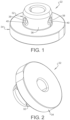
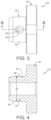
Fig. 1 is a perspective view of one example of an annular collar of a press-fit, friction-retention coupling assembly in accordance with the present disclosure. -
Fig. 2 is another perspective view of the annular collar ofFig. 1 . -
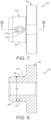
Fig. 3 is a side elevation view of the annular collar ofFig. 1 . -
Fig. 4 is a cross-section view taken through line 4-4 ofFig. 3 . -
Fig. 5 is a perspective view of another example of an annular collar of a press-fit, friction-retention coupling assembly in accordance with the present disclosure. -
Fig. 6 is another perspective view of the annular collar ofFig. 5 . -
Fig. 7 is a side elevation view of the annular collar ofFig. 5 . -
Fig. 8 is a cross-section view taken through line 8-8 ofFig. 7 . -
Fig. 9 is a partial cross-section view of alternative recess and protrusion designs in accordance with the present disclosure. -
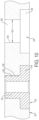
Fig. 10 is a cross-section view of an example press-fit, friction-retention coupling assembly in accordance with the present disclosure. - Corresponding reference numerals indicate corresponding parts throughout the several views of the drawings.
- Example embodiments will now be described more fully with reference to the accompanying drawings.
- With reference to
Figs. 1-10 examples of a press-fit, friction-retention coupling assembly in accordance with the present disclosure are detailed herein. The same reference numbers are used to identify corresponding features throughout the drawings with respect to different example embodiments, regardless of whether the corresponding features are identical or not. The example press-fit, friction-retention coupling assemblies include anouter component 20 and anannular collar 22. Theouter component 20 can be formed of an outer material having a Rockwell R hardness of at least 95. In some cases, the Rockwell R hardness of theouter component 20 can be at least 100, 110, 120, or more. In some cases, theouter component 20 can be formed of a metal. - The outer component 20 (
Fig. 10 ) includes arecess 24 therein for receiving theannular collar 22. Therecess 24 can be a through-opening in theouter component 20 as illustrated. Alternatively, therecess 24 can extend only partially though theouter component 20. Separately, therecess 24 can be a stepped recess in which each steppedportion 26, 28 has a different diameter. Therecess 24 defines an outercomponent mating wall 30. As in the illustrated example, thismating wall 30 of theouter component 20 can be defined by the smallerdiameter step portion 28 of therecess 24. In some other examples, therecess 24 can have a single constant diameter throughout, or the larger diameter step portion can provide the outercomponent mating wall 30. - The
annular collar 22 can be formed of a collar material having a Rockwell R hardness of at least 95. In some cases, the Rockwell R hardness of the collar material of theannular collar 22 can be at least 100, 110, or 120. Theannular collar 22 can be formed of a hard polymer material. One exemplary class of such hard polymer materials is glass-filled polymers. One example of a glass-filled polymer comprises polyphenylene sulfide. One example of a glass-filled polymer comprising polyphenylene sulfide is sold by Polyplastics Co., LTD. of Tokyo, Japan, under the trade name polyphenylene sulfide®. - The
annular collar 22 can have a stepped shape in which eachstep portion annular collar 22 defines an annularcollar mating wall 36. As in the illustrated example, thismating wall 36 of theannular collar 22 can be defined by the smallerdiameter step portion 32 of theannular collar 22. In some other examples, theannular collar 22 can have a single constant diameter throughout, or the larger diameter step portion can provide the annularcollar mating wall 36. - The annular
collar mating wall 36 can include at least threeprotrusions 38 with eachprotrusion 38 being surrounded by arecess 40 in themating wall 36 so that anoverall protrusion height 42 between abase 44 of theprotrusion 38 and adistal end 46 thereof is greater than a protruding distance 50 between anouter diameter 48 of a cylindricalouter surface 54 of the annular collar mating wall 36 (i.e., excluding the protrusions 38) and thedistal end 46 of theprotrusion 38. - The number and configuration of the
protrusions 38 of the annularcollar mating wall 36 are designed to provide a press-fit insertion force low enough to enable an assembly line worker to manually insert theannular collar 22 into therecess 24 throughout relevant tolerance ranges for themating walls 30, 36 (including the protrusions 38). In addition, the number and configuration of theprotrusions 38 of the annularcollar mating wall 36 are also designed to frictionally retain theannular collar 22 within therecess 24 of theouter component 20 under the overall weight of theannular collar 22 throughout relevant tolerance ranges for themating walls components annular collar 22 generates the greatest removal force due to the effects of gravity. - As in the example embodiments, a contacting relationship between the
protrusions 38 of the annularcollar mating wall 36 and the outercomponent mating wall 30 generates a press-fit insertion force that is 50 Newtons or less throughout the relevant tolerance ranges for themating walls mating walls protrusions 38 of the annularcollar mating wall 36 and the outercomponent mating wall 30 can generate a friction retention force of at least 5, at least 10 Newtons or at least 20 Newtons throughout the relevant tolerance ranges for themating walls - The "relevant tolerance ranges for the mating walls" as used herein relate to the tolerance range for the
inner diameter 52 of themating wall 30 of theouter component 20 and for the outer diameter of the mating wall 36 (including the protrusions 38) of theannular collar 22. Thus, "throughout relevant tolerance ranges" spans from a minimum interference corresponding to the largestpermissible diameter 52 of themating wall 30 of therecess 24 in combination with the smallest permissible diameter of the mating wall 36 (including the protrusions 38) of theannular collar 22, to a maximum interference corresponding to the smallestpermissible diameter 52 of themating wall 30 of therecess 24 in combination with the largest permissible diameter of the mating wall 36 (including the protrusions 38) of theannular collar 22. - As in the example embodiments, the
protrusions 38 can provide the only contact between themating walls mating walls protrusions 38 can provide the only contact between theannular collar 22 and any axially extending portion of therecess 24 of theouter component 20. In other words, there is also a cylindrical gap between the adjacent cylindrical surfaces of the steppedportions 26, 34. - As in the example embodiments of
Figs. 1-4 ,9 , and10 theannular recess 40 surrounding theprotrusion 38 can have a teardrop shape. In addition, a pointed end of theteardrop shape recess 40 can be oriented toward an insertion end of themating wall 36 of theannular collar 22. As in the example embodiments ofFigs. 5-8 ,9 , and10 , theannular recess 40 surrounding theprotrusion 38 can have a diamond shape. In addition, the diamondshape surrounding recess 40 can be elongated and can be oriented with the elongated overall dimension extending parallel to a central axis of themating wall 36 of theannular collar 22. In some other embodiments, different shapes of theannular recess 40 are possible. - Referring to
Fig. 9 , lines representing fourdifferent cross-sections protrusions 38 with surroundingrecesses 40 are illustrated. For better clarity, thebase 44, overall distance orheight 42 of theprotrusion 38 are only referenced inFig. 9 with respect to thecross-section 62. Two of the cross-sections 56, 58 correspond toprotrusions 38 with annular recesses having the teardrop shape and orientation as illustrated inFigs. 1-6 . The difference between these twocross-sections respective protrusion 38 has anoverall height 42 that is greater forcross-section 56 than forcross-section 58, due to the increased depth of the respective surroundingrecess 40. In addition, the portion of therespective protrusion 38 within the protruding distance 50 has an axially aligned radius that is greater forcross-section 58 than forcross-section 56. - Two of the cross-sections 60, 62 correspond to
protrusions 38 with annular recesses having the diamond shape and orientation ofFigs. 5-8 . The difference between these twocross-sections respective protrusion 38 has anoverall height 42 that is greater forcross-section 62 than forcross-section 60, due to the increased depth of the respective surroundingrecess 40. In addition, the portion of therespective protrusion 38 within the protruding distance 50 has an axially aligned radius that is greater forcross-section 60 than forcross-section 62. - As in the example embodiments, the
overall protrusion height 42 between the base 44 of theprotrusion 38 and thedistal end 46 of eachprotrusion 38 can be at least 4.5 times, 5.5 times, or 6 times the protruding distance 50, which is the distance between theouter diameter 48, a cylindricalouter surface 54 of the annular collar mating wall 36 (excluding the protrusions 38), and thedistal end 46 of theprotrusion 38. In some embodiments, thisoverall protrusion height 42 can be up to 10.5 times, or 8.5 times the protruding distance 50 for eachprotrusion 38. - As in the example embodiments, in some cases the portion of each
protrusion 38 within the protruding distance 50 can have an axially aligned radius that can be at least 0 mm, at least 0.01 mm, at least 0.2 mm, or at least 0.4 mm. Additionally or alternatively, in some embodiments, the portion of eachprotrusion 38 within the protruding distance 50 has an axially aligned radius that can be up to 2.0 mm, up to 1.5 mm, or up to 1.3 mm. - As in the example embodiments, in some cases the minimum interference between the
protrusions 38 of the annularcollar mating wall 36 and themating wall 30 of therecess 24 of theouter component 20 throughout the relevant tolerance ranges can be at least 0 mm, at least 0.01 mm, or 0.02 mm. Alternatively or additionally, the maximum interference between theprotrusions 38 of the annularcollar mating wall 36 and themating wall 30 of therecess 24 of theouter component 20 throughout the relevant tolerance ranges can be up to 0.07 mm, up to 0.05 mm, or up to 0.03 mm. - In some cases, a plurality of press-fit, friction-retention coupling assembly be used in forming a fuel cell stack. In some cases, the collar material forming the
annular collar 22 can have a high chemical resistance. In some cases, the collar material forming theannular collar 22 can have a high temperature resistance. For example, the inner material forming theannular collar 22 can have a temperature resistance that is at least -40 degrees C and up to 266 degrees C. - The foregoing description of the embodiments has been provided for purposes of illustration and description. It is not intended to be exhaustive or to limit the disclosure. Individual elements or features of a particular embodiment are generally not limited to that particular embodiment, but, where applicable, are interchangeable and can be used in a selected embodiment, even if not specifically shown or described. The same may also be varied in many ways. Such variations are not to be regarded as a departure from the disclosure, and all such modifications are intended to be included within the scope of the disclosure.
Claims (13)
- A press-fit, friction-retention coupling assembly comprising:an outer component (20) having a recess (24) therein defining an outer component mating wall (30);an annular collar (22) configured to be inserted into the recess (24) in the outer component, the annular collar (22) having an annular collar mating wall (36) with a cylindrical outer surface and including a number of protrusions (38), each protrusion (38) being surrounded by a recess (40) so that an overall protrusion height between a base of the protrusion (38) and a distal end thereof is greater than a protruding distance between an outer diameter (48) of the cylindrical outer surface (54) of the annular collar mating wall (36) and the distal end (46) of the protrusion (38); andwherein the number and configuration of the protrusions (38) are designed to provide a press-fit insertion force of 50 Newtons or less throughout relevant tolerance ranges for the outer component mating wall and the annular collar mating wall, and to provide a friction retention force sufficient to retain the annular collar (22) within the recess (40) of the outer component under an overall weight of the annular collar throughout relevant tolerance ranges for the mating walls.
- The press-fit, friction-retention coupling assembly according to claim 1, wherein the outer component is formed of an outer material having a Rockwell R hardness of at least 95 and the collar is formed of a collar material having a Rockwell R hardness of at least 95.
- The press-fit, friction-retention coupling assembly according to claim 1 or 2, wherein the outer material is a metal and the collar material comprises a polymer material.
- The press-fit, friction-retention coupling assembly according to claim 3, wherein the collar material is a glass-filled polymer.
- The press-fit, friction-retention coupling assembly according to claim 3, wherein the collar material comprises polyphenylene sulfide.
- The press-fit, friction-retention coupling assembly according to any of claims 1-5, wherein the protrusions (38) provide the only contact between the outer component mating wall (30) and the annular collar mating wall (36) throughout the relevant tolerance ranges for the annular collar mating wall and the outer component mating wall.
- The press-fit, friction-retention coupling assembly according to any of claims 1-6, wherein the recess (40) surrounding the protrusion (38) has a teardrop shape.
- The press-fit, friction-retention coupling assembly according to claim 7, wherein a pointed end of the teardrop shape is oriented toward an insertion end of the annular collar mating wall (36).
- The press-fit, friction-retention coupling assembly according to any of claims 1-6, wherein the recess (40) surrounding the protrusion (38) has a diamond shape.
- The press-fit, friction-retention coupling assembly according to claim 9, wherein the diamond shape is elongated and oriented with an elongated overall dimension extending parallel to a central axis of the annular collar (22).
- The press-fit, friction-retention coupling assembly according to any of claims 1-10, wherein the overall protrusion height (42) of each protrusion (38) is between 4.5 times and 10.5 times the protruding distance.
- The press-fit, friction-retention coupling assembly according to any of claims 1-11, wherein a minimum and a maximum interference between the recess (40) of the outer component and the annular collar (22) including the protrusions throughout the relevant tolerance ranges for the collar mating wall and the outer component mating wall is 0 mm or more and 0.07 mm or less, respectively.
for the mating walls, is 0.1 mm or more and 0.05 mm or less, respectively. - The press-fit, friction-retention coupling assembly according to any of claims 1-12, wherein an axially aligned radius of the protrusion (38) within the protruding distance is 0.1 mm or more.
Applications Claiming Priority (3)
| Application Number | Priority Date | Filing Date | Title |
|---|---|---|---|
| US16/522,185 US11486520B2 (en) | 2019-07-25 | 2019-07-25 | Press-fit, friction-retention coupling assembly between hard, inflexible material components |
| PCT/US2019/044687 WO2021015800A1 (en) | 2019-07-25 | 2019-08-01 | Press-fit, friction-retention coupling assembly between hard, inflexible material components |
| EP19938603.8A EP4004386B1 (en) | 2019-07-25 | 2019-08-01 | Press-fit, friction-retention coupling assembly between hard, inflexible material components |
Related Parent Applications (2)
| Application Number | Title | Priority Date | Filing Date |
|---|---|---|---|
| EP19938603.8A Division EP4004386B1 (en) | 2019-07-25 | 2019-08-01 | Press-fit, friction-retention coupling assembly between hard, inflexible material components |
| EP19938603.8A Division-Into EP4004386B1 (en) | 2019-07-25 | 2019-08-01 | Press-fit, friction-retention coupling assembly between hard, inflexible material components |
Publications (3)
| Publication Number | Publication Date |
|---|---|
| EP4418373A2 true EP4418373A2 (en) | 2024-08-21 |
| EP4418373A3 EP4418373A3 (en) | 2024-10-16 |
| EP4418373B1 EP4418373B1 (en) | 2026-04-22 |
Family
ID=74190139
Family Applications (2)
| Application Number | Title | Priority Date | Filing Date |
|---|---|---|---|
| EP24186648.2A Active EP4418373B1 (en) | 2019-07-25 | 2019-08-01 | Press-fit, friction-retention coupling assembly between hard, inflexible material components |
| EP19938603.8A Active EP4004386B1 (en) | 2019-07-25 | 2019-08-01 | Press-fit, friction-retention coupling assembly between hard, inflexible material components |
Family Applications After (1)
| Application Number | Title | Priority Date | Filing Date |
|---|---|---|---|
| EP19938603.8A Active EP4004386B1 (en) | 2019-07-25 | 2019-08-01 | Press-fit, friction-retention coupling assembly between hard, inflexible material components |
Country Status (5)
| Country | Link |
|---|---|
| US (2) | US11486520B2 (en) |
| EP (2) | EP4418373B1 (en) |
| JP (1) | JP7418546B2 (en) |
| CN (1) | CN114207300B (en) |
| WO (1) | WO2021015800A1 (en) |
Family Cites Families (45)
| Publication number | Priority date | Publication date | Assignee | Title |
|---|---|---|---|---|
| US1227627A (en) * | 1914-06-19 | 1917-05-29 | Clements Company | Wall-socket. |
| US1488948A (en) * | 1921-12-14 | 1924-04-01 | Oscar A Smith | Binding post |
| US1719137A (en) * | 1922-06-26 | 1929-07-02 | Rosenberg Heyman | Metallic fastener |
| US2191771A (en) * | 1937-09-16 | 1940-02-27 | Illinois Tool Works | Fastener |
| US2393923A (en) * | 1944-02-29 | 1946-01-29 | Miller Edwin August | Multiple anchoring means |
| US3019460A (en) * | 1956-10-22 | 1962-02-06 | John C Corckran | Method of making rounded head nail |
| US2993923A (en) * | 1959-08-20 | 1961-07-25 | Phillips Petroleum Co | Preparation of cuprous tertiarybutyl sulfonium chloride and its use as a selective herbicide |
| US3515419A (en) * | 1968-07-01 | 1970-06-02 | Huck Mfg Co | Container fastener |
| GB1348152A (en) * | 1971-10-12 | 1974-03-13 | Lamson Sessions Co | Interference member |
| JPS6334950Y2 (en) * | 1980-06-04 | 1988-09-16 | ||
| US4340145A (en) * | 1980-07-18 | 1982-07-20 | Cameron Anson W | Caddy for garment hangers |
| JPH0225922Y2 (en) | 1985-09-30 | 1990-07-16 | ||
| US4776739A (en) | 1986-04-14 | 1988-10-11 | Illinois Tool Works Inc. | Plastic drive fastener |
| US4760752A (en) | 1987-04-01 | 1988-08-02 | Hewlett-Packard Company | Plastic deformation relief |
| US5362172A (en) | 1992-08-31 | 1994-11-08 | Minnesota Mining And Manufacturing Company | Press fit assembly boss for diskettes |
| US20050025609A1 (en) * | 1996-01-03 | 2005-02-03 | Oxford J. Craig | Surface mount ring assembly for loudspeaker |
| DE19812367A1 (en) * | 1997-04-17 | 1998-10-22 | Emhart Inc | Assembly system with fastening bolts and method for forming an assembly system |
| US5897401A (en) * | 1997-07-01 | 1999-04-27 | Solid State Stamping, Inc. | Serrated starred pin |
| US6042429A (en) * | 1997-08-18 | 2000-03-28 | Autosplice Systems Inc. | Continuous press-fit knurl pin |
| US6431023B1 (en) * | 1998-02-12 | 2002-08-13 | Ohi Seisakusho Co., Ltd. | Lever pivoting structure |
| DE19856611A1 (en) * | 1998-12-08 | 2000-06-15 | Boellhoff Gmbh | Metallic insert |
| JP2001234912A (en) | 2000-02-21 | 2001-08-31 | Kondotec Inc | Stone mooring fittings and stone |
| JP2002130219A (en) * | 2000-10-23 | 2002-05-09 | Iris Ohyama Inc | Press-fitting member, coupling tool, and pipe-coupling structure using them |
| DE10058520C1 (en) * | 2000-11-24 | 2002-07-04 | Itw Automotive Prod Gmbh & Co | Device for fastening a disk-shaped component in a receptacle |
| DE10107952C1 (en) * | 2001-02-20 | 2002-04-04 | Airbus Gmbh | Locking ring bolt, for sealed mechanical connection, has profiled locking region of bolt shaft provided with diamond profiles for distribution of sealing mass |
| EP1324312B1 (en) * | 2001-11-08 | 2008-02-13 | Yamaha Corporation | Keyboard musical instrument having keys regulated with stable key balance pieces |
| JP4127532B2 (en) | 2003-09-25 | 2008-07-30 | 株式会社青山製作所茨城工場 | Two-member hermetic joint structure made of different material members and method of joining the same |
| US7377823B2 (en) | 2005-05-23 | 2008-05-27 | J.S.T. Corporation | Press-fit pin |
| JP4395465B2 (en) * | 2005-07-11 | 2010-01-06 | 永山電子工業株式会社 | Insert nut and insert T-nut |
| US8091800B2 (en) * | 2006-04-09 | 2012-01-10 | Netafim, Ltd. | Drippers and pipe couplers |
| DE102008033307A1 (en) * | 2008-07-16 | 2010-01-21 | Newfrey Llc, Newark | fastening device |
| JP5168694B2 (en) * | 2008-12-24 | 2013-03-21 | ポップリベット・ファスナー株式会社 | clip |
| EP2336586B1 (en) | 2009-12-15 | 2013-08-14 | Maxon Motor AG | Method for creating a tight fit of a component to a shaft |
| BR112012025378A2 (en) * | 2010-04-16 | 2016-06-28 | Illinois Tool Works | spiral insert with ring rod notch |
| KR101143331B1 (en) * | 2011-09-21 | 2012-05-09 | 지이엔 주식회사 | Insert nut having a diamond structure and method for manufacturing thereof |
| US9771964B2 (en) * | 2012-11-06 | 2017-09-26 | Inter Ikea Systems B.V. | Fastening device, fastening system and furniture assembly |
| DE102013210889A1 (en) | 2013-06-11 | 2014-12-11 | Robert Bosch Gmbh | connecting device |
| US9458876B2 (en) * | 2013-08-28 | 2016-10-04 | GM Global Technology Operations LLC | Elastically deformable alignment fastener and system |
| CN105817879B (en) | 2015-01-07 | 2019-03-05 | 富泰华工业(深圳)有限公司 | Coaxial assembly structure and assembly method thereof |
| US10094494B2 (en) | 2015-06-26 | 2018-10-09 | Agilent Technologies, Inc. | Ferrule with features for softening ferrule crush and related methods |
| US9862166B2 (en) * | 2016-03-07 | 2018-01-09 | The Boeing Company | Adjustable-height inserts and related methods |
| CN205908677U (en) | 2016-06-06 | 2017-01-25 | 深圳市祈飞科技有限公司 | Bumper |
| WO2018198213A1 (en) | 2017-04-26 | 2018-11-01 | 日産自動車株式会社 | Structure for press-fitting and fixing metal collar to resin member and press-fit fixing method |
| US10704581B2 (en) * | 2017-11-14 | 2020-07-07 | Penn Engineering & Manufacturing Corp. | Press-in fastener with a wavy knurled shank |
| GB2576956B (en) * | 2018-09-10 | 2022-06-08 | Intelligent Fixings Ltd | Dowel fasteners |
-
2019
- 2019-07-25 US US16/522,185 patent/US11486520B2/en active Active
- 2019-08-01 WO PCT/US2019/044687 patent/WO2021015800A1/en not_active Ceased
- 2019-08-01 JP JP2022504650A patent/JP7418546B2/en active Active
- 2019-08-01 EP EP24186648.2A patent/EP4418373B1/en active Active
- 2019-08-01 EP EP19938603.8A patent/EP4004386B1/en active Active
- 2019-08-01 CN CN201980098737.2A patent/CN114207300B/en active Active
-
2022
- 2022-10-27 US US17/974,625 patent/US12486926B2/en active Active
Also Published As
| Publication number | Publication date |
|---|---|
| EP4418373B1 (en) | 2026-04-22 |
| EP4004386A1 (en) | 2022-06-01 |
| EP4004386A4 (en) | 2023-08-16 |
| WO2021015800A1 (en) | 2021-01-28 |
| EP4418373A3 (en) | 2024-10-16 |
| US20230048081A1 (en) | 2023-02-16 |
| US12486926B2 (en) | 2025-12-02 |
| US11486520B2 (en) | 2022-11-01 |
| US20210025521A1 (en) | 2021-01-28 |
| CN114207300A (en) | 2022-03-18 |
| JP2022550241A (en) | 2022-12-01 |
| EP4004386B1 (en) | 2024-10-02 |
| JP7418546B2 (en) | 2024-01-19 |
| CN114207300B (en) | 2024-04-02 |
Similar Documents
| Publication | Publication Date | Title |
|---|---|---|
| CN112242625B (en) | Connecting plug, forming method thereof, plug-in connector and connecting socket | |
| US6194661B1 (en) | Duplex connector | |
| EP2254398B1 (en) | Support member of circuit board | |
| US9711873B1 (en) | Crimp terminal and connector | |
| EP2131084A2 (en) | Fastening element for fastening a structural part to a pin | |
| US7364472B2 (en) | Connector | |
| WO1999026010A1 (en) | Fluid coupling assembly, locking member therefor and method of assembly | |
| US6176666B1 (en) | Spacing sleeve | |
| JP6580797B2 (en) | Assembly having contact elements and electrical conductors and method for manufacturing the assembly | |
| EP4418373B1 (en) | Press-fit, friction-retention coupling assembly between hard, inflexible material components | |
| US10411381B2 (en) | Electrical contact | |
| EP3043099A1 (en) | Sealing member for pipe connection comprising protrusions | |
| CN113039687B (en) | Guide pin retainer for guide pins in adapter | |
| EP3488497B1 (en) | Cable-mountable connector | |
| EP2113706A1 (en) | Press fit connector with improved coupling part for holding a press sleeve | |
| EP3586217B1 (en) | Sensing tip retention | |
| US6398597B1 (en) | Receptacle contact of a cable assembly and the cable assembly using the same | |
| JP2018185025A (en) | chain | |
| JP4857884B2 (en) | connector | |
| JP4777742B2 (en) | Storage case with shank holder | |
| US20240322477A1 (en) | Crown Spring with Alternating Spring Blade Design | |
| US20240297465A1 (en) | Outer conductor contact for a connector and connector | |
| US11739777B2 (en) | Alignment feature for an elastic averaging alignment system | |
| JP2022550241A5 (en) | ||
| JP2009140752A (en) | Terminal chain and connector assembly method |
Legal Events
| Date | Code | Title | Description |
|---|---|---|---|
| PUAI | Public reference made under article 153(3) epc to a published international application that has entered the european phase |
Free format text: ORIGINAL CODE: 0009012 |
|
| STAA | Information on the status of an ep patent application or granted ep patent |
Free format text: STATUS: THE APPLICATION HAS BEEN PUBLISHED |
|
| AC | Divisional application: reference to earlier application |
Ref document number: 4004386 Country of ref document: EP Kind code of ref document: P |
|
| AK | Designated contracting states |
Kind code of ref document: A2 Designated state(s): AL AT BE BG CH CY CZ DE DK EE ES FI FR GB GR HR HU IE IS IT LI LT LU LV MC MK MT NL NO PL PT RO RS SE SI SK SM TR |
|
| REG | Reference to a national code |
Ref country code: DE Ref legal event code: R079 Free format text: PREVIOUS MAIN CLASS: H01M0008000000 Ipc: F16B0004000000 Ref country code: DE Ref legal event code: R079 Ref document number: 602019084111 Country of ref document: DE Free format text: PREVIOUS MAIN CLASS: H01M0008000000 Ipc: F16B0004000000 |
|
| PUAL | Search report despatched |
Free format text: ORIGINAL CODE: 0009013 |
|
| AK | Designated contracting states |
Kind code of ref document: A3 Designated state(s): AL AT BE BG CH CY CZ DE DK EE ES FI FR GB GR HR HU IE IS IT LI LT LU LV MC MK MT NL NO PL PT RO RS SE SI SK SM TR |
|
| RIC1 | Information provided on ipc code assigned before grant |
Ipc: H01M 8/00 20160101ALN20240911BHEP Ipc: F16B 17/00 20060101ALN20240911BHEP Ipc: F16B 2/00 20060101ALI20240911BHEP Ipc: F16B 4/00 20060101AFI20240911BHEP |
|
| STAA | Information on the status of an ep patent application or granted ep patent |
Free format text: STATUS: REQUEST FOR EXAMINATION WAS MADE |
|
| 17P | Request for examination filed |
Effective date: 20250416 |
|
| GRAP | Despatch of communication of intention to grant a patent |
Free format text: ORIGINAL CODE: EPIDOSNIGR1 |
|
| STAA | Information on the status of an ep patent application or granted ep patent |
Free format text: STATUS: GRANT OF PATENT IS INTENDED |
|
| RIC1 | Information provided on ipc code assigned before grant |
Ipc: F16B 4/00 20060101AFI20250623BHEP Ipc: F16B 2/00 20060101ALI20250623BHEP Ipc: F16B 17/00 20060101ALN20250623BHEP Ipc: H01M 8/00 20160101ALN20250623BHEP |
|
| INTG | Intention to grant announced |
Effective date: 20250704 |
|
| GRAJ | Information related to disapproval of communication of intention to grant by the applicant or resumption of examination proceedings by the epo deleted |
Free format text: ORIGINAL CODE: EPIDOSDIGR1 |
|
| STAA | Information on the status of an ep patent application or granted ep patent |
Free format text: STATUS: REQUEST FOR EXAMINATION WAS MADE |
|
| GRAS | Grant fee paid |
Free format text: ORIGINAL CODE: EPIDOSNIGR3 |
|
| STAA | Information on the status of an ep patent application or granted ep patent |
Free format text: STATUS: GRANT OF PATENT IS INTENDED |
|
| GRAP | Despatch of communication of intention to grant a patent |
Free format text: ORIGINAL CODE: EPIDOSNIGR1 |
|
| INTC | Intention to grant announced (deleted) | ||
| RIC1 | Information provided on ipc code assigned before grant |
Ipc: F16B 4/00 20060101AFI20251104BHEP Ipc: F16B 2/00 20060101ALI20251104BHEP Ipc: F16B 17/00 20060101ALN20251104BHEP Ipc: H01M 8/00 20160101ALN20251104BHEP |
|
| INTG | Intention to grant announced |
Effective date: 20251118 |
|
| GRAA | (expected) grant |
Free format text: ORIGINAL CODE: 0009210 |
|
| STAA | Information on the status of an ep patent application or granted ep patent |
Free format text: STATUS: THE PATENT HAS BEEN GRANTED |
|
| AC | Divisional application: reference to earlier application |
Ref document number: 4004386 Country of ref document: EP Kind code of ref document: P |
|
| AK | Designated contracting states |
Kind code of ref document: B1 Designated state(s): AL AT BE BG CH CY CZ DE DK EE ES FI FR GB GR HR HU IE IS IT LI LT LU LV MC MK MT NL NO PL PT RO RS SE SI SK SM TR |
|
| REG | Reference to a national code |
Ref country code: CH Ref legal event code: F10 Free format text: ST27 STATUS EVENT CODE: U-0-0-F10-F00 (AS PROVIDED BY THE NATIONAL OFFICE) Effective date: 20260422 Ref country code: GB Ref legal event code: FG4D |
|
| REG | Reference to a national code |
Ref country code: DE Ref legal event code: R096 Ref document number: 602019084111 Country of ref document: DE |