EP4418236A1 - Uam corridor visual indication - Google Patents
Uam corridor visual indication Download PDFInfo
- Publication number
- EP4418236A1 EP4418236A1 EP23212327.3A EP23212327A EP4418236A1 EP 4418236 A1 EP4418236 A1 EP 4418236A1 EP 23212327 A EP23212327 A EP 23212327A EP 4418236 A1 EP4418236 A1 EP 4418236A1
- Authority
- EP
- European Patent Office
- Prior art keywords
- corridor
- aircraft
- graphic
- display
- relative distance
- Prior art date
- Legal status (The legal status is an assumption and is not a legal conclusion. Google has not performed a legal analysis and makes no representation as to the accuracy of the status listed.)
- Pending
Links
Images



Classifications
-
- G—PHYSICS
- G08—SIGNALLING
- G08G—TRAFFIC CONTROL SYSTEMS
- G08G5/00—Traffic control systems for aircraft
- G08G5/20—Arrangements for acquiring, generating, sharing or displaying traffic information
- G08G5/21—Arrangements for acquiring, generating, sharing or displaying traffic information located onboard the aircraft
-
- G—PHYSICS
- G08—SIGNALLING
- G08G—TRAFFIC CONTROL SYSTEMS
- G08G5/00—Traffic control systems for aircraft
- G08G5/50—Navigation or guidance aids
- G08G5/53—Navigation or guidance aids for cruising
-
- G—PHYSICS
- G08—SIGNALLING
- G08G—TRAFFIC CONTROL SYSTEMS
- G08G5/00—Traffic control systems for aircraft
- G08G5/50—Navigation or guidance aids
- G08G5/55—Navigation or guidance aids for a single aircraft
-
- G—PHYSICS
- G08—SIGNALLING
- G08G—TRAFFIC CONTROL SYSTEMS
- G08G5/00—Traffic control systems for aircraft
- G08G5/50—Navigation or guidance aids
- G08G5/57—Navigation or guidance aids for unmanned aircraft
-
- G—PHYSICS
- G08—SIGNALLING
- G08G—TRAFFIC CONTROL SYSTEMS
- G08G5/00—Traffic control systems for aircraft
- G08G5/50—Navigation or guidance aids
- G08G5/59—Navigation or guidance aids in accordance with predefined flight zones, e.g. to avoid prohibited zones
Definitions
- the present disclosure relates generally to displaying corridors on flight displays, and, more particularly, to displaying a graphic related to Urban Air Mobility (UAM) corridors based on a relative distance to the UAM corridors.
- UAM Urban Air Mobility
- UAM ConOPS V1.0 titled "Concept of Operations" created by the FAA aircraft must operate under UAM specific rules, procedures, and Community based Rules (CBRS) when operating in UAM Corridors (e.g., static as well as Dynamic Delegated Corridors).
- CBRS Community based Rules
- UAM Fixed wing and Unmanned Traffic Management (UTM) aircraft operate across corridors. Helicopters and UAM aircraft operate within and across corridors. When these aircrafts are outside corridors relevant ATM rules are applicable. A visual indication to remind/inform the users near corridors of relevant corridor rules or ATM/UTM rules may be desired.
- the system may include a display and a processor.
- the processor may be configured to receive corridor position data of a corridor and aircraft position data indicative of a position of an aircraft.
- the processor may be configured to determine a relative distance of the aircraft in relation to the corridor based on the corridor position data and the aircraft position data.
- the processor may be configured to display a corridor graphic associated with the corridor based on the relative distance.
- the method may include receiving corridor position data of a corridor and aircraft position data indicative of a position of an aircraft.
- the method may include determining a relative distance of the aircraft in relation to the corridor based on the corridor position data and the aircraft position data.
- the method may include displaying a corridor graphic associated with the corridor based on the relative distance.
- a system, method, and device configured to warn pilots of Urban Air Mobility (UAM) corridors.
- the system includes a warning unit on-board an aircraft that receives UAM corridor data from a database, and correlates the data with aircraft position data and/or flight plan data derived from a navigation system to determine if the aircraft is approaching a known UAM corridor that may require following relevant UAM corridor rules. If a UAM corridor is identified, a graphic may be displayed to the user to increase situational awareness, such as allowing a pilot to prepare to follow relevant UAM rules.
- AAM Advanced Air Mobility
- use cases that are not necessarily urban in nature include, but are not necessarily limited to, Commercial Inter-city (Longer Range/Thin Haul), Cargo Delivery, Public Services, Private/Recreational Vehicles, and/or the like.
- Commercial Inter-city Longer Range/Thin Haul
- Cargo Delivery Public Services
- Private/Recreational Vehicles and/or the like.
- UAM and AAM may be used interchangeably.
- embodiments of the inventive concepts disclosed herein are directed to a system and method for graphical indication of a corridor relative to an aircraft.
- two display modes may be used, one for showing a relative distance when approaching a corridor, and one for showing, generally, that the aircraft is already located in the corridor.
- These modes may generally improve a user's (e.g., pilot's) situational awareness by prominently being displayed in relevant areas of a display.
- FIG. 1 is a system 100 for a graphical indication of a corridor, in accordance with one or more embodiments of this disclosure.
- the system 100 includes a warning unit 110, in communication with a navigation system 120, a database 130 and a user interface 140.
- the navigation system 120 is disposed within the aircraft.
- the warning unit 110 may additionally include, but is not limited to, a controller 150.
- the system 100 is configured for an aircraft.
- the system 100 may be configured for any aircraft known, including but not limited to, fixed-wing aircraft or rotorcraft.
- the warning unit 110 includes hardware, software, and/or firmware configured to execute the various functions or steps described herein.
- the controller 150 is configured to receive, process, and transmit data within the system 100.
- the controller 150 includes one or more processors 160 configured to perform functions or steps according to program instructions stored in a memory 170.
- the controller may also send and receive data and signals via a communication interface 180 to other components of the warning unit 110 and/or the system 100.
- the controller 150 may be configured to receive corridor position data from the database 130 and aircraft position data from the navigation system 120, process the data (e.g., determine a relative distance between the corridor position data to the aircraft position data), and display graphics (e.g., a corridor graphic associated with the corridor) to the user interface 140.
- operable to may mean being configured to execute software such as program instructions stored on the memory 170, and/or the like.
- the user interface 140 may include any device capable of displaying data to a user and/or receiving data input from a user including but not limited to a display 145, a keyboard, a joystick, a mouse, an audio device, or a haptic device.
- the user interface may include a display 145 in combination with a keyboard.
- the user interface may include a display 145 with a touchscreen.
- the user interface 140 may be physical linked with the warning unit 110.
- the warning unit 110 and the user interface 140 may be configured as single modular unit.
- the user interface 140 may be physically detached from the warning unit 110.
- the user interface 140 and the warning unit 110 may both be on-board an aircraft, but linked only communicatively via a wireline or wireless connection.
- the display 145 may be integrated with a touchscreen interface, such as, but not limited to, a capacitive touchscreen, a resistive touchscreen, a surface acoustic based touchscreen, an infrared based touchscreen, or the like.
- a touchscreen interface such as, but not limited to, a capacitive touchscreen, a resistive touchscreen, a surface acoustic based touchscreen, an infrared based touchscreen, or the like.
- any touchscreen display capable of integration with the system 100 is suitable for implementation in the present invention.
- the display 145 may include any type of display device known in the art.
- the display may include, but are not limited to, a liquid crystal display (LCD), a light-emitting diode (LED) based display, an organic light-emitting diode (OLED) based display, an electroluminescent display (ELD), an electronic paper (E-ink) display, a plasma display panel (PDP), a display light processing (DLP) display, a cathode-ray tube (CRT), or the like.
- LCD liquid crystal display
- LED light-emitting diode
- OLED organic light-emitting diode
- ELD electroluminescent display
- E-ink electronic paper
- PDP plasma display panel
- DLP display light processing
- CTR cathode-ray tube
- the user interface 140 may include a display 145 that is part of, or incorporated into, a primary flight display (PFD), an aircraft instrument dedicated to flight information.
- the display 145 may be configured as a picture-in-picture (PIP) display within a PFD, wherein data from the system 100 is displayed as the first image along with other data from different aircraft systems displayed as a second image.
- PIP picture-in-picture
- data from the system 100 is overlaid on a PFD that has incorporates data from other systems.
- data from the system 100 may appear as icons/symbols/graphics on an aircraft display that are overlaid upon, or incorporated into a virtual landscape on the PFD that corresponds to the position of the aircraft.
- the data from the system 100 may be maximized to cover an entire quadrant of the PFD.
- the display 145 may be minimized on the PFD.
- the PFD, and/or a portion of the PFD may be configured as a display 145 for the system 100.
- the user interface 140 may include a display that is part of, or incorporated into, a map display and/or a navigation display.
- the display may be similarly configured for use with the map display and/or navigation display as described for the PFD described herein.
- the user interface 140 may include any display or type of display used onboard an aircraft.
- the display may include a primary flight display (PFD).
- the display may also include any type of virtualized or augmented vision system including but not limited to a synthetic vision system (SVS), a heads-up display (HUD) a head-mounted display (HMD), a virtual reality (VR) system, a mixed reality (MR) system, an augmented reality (AR) system and an extended reality (XR) system.
- the user interface may be an SVS display, wherein data from the system 100 is incorporated into the SVS display.
- the database 130 stores the location of a plurality of UAM corridors for vehicles operating under UAM rules.
- UAM and/or AAM a safe and efficient aviation transportation system
- highly automated aircraft e.g., automated vertical takeoff taxis, etc.
- lower altitudes e.g., between 400 to 1500 feet, between 400 to 3,000 feet, 990 feet and below, and/or the like as decided by UAM authorities
- UAM ecosystem One possible result of a UAM ecosystem is the creation of a database 130 that stores the location of corridors (e.g., areas that are likely to have UAM vehicles in the air)). Data from this database 130 may be then be shared within components of the system 100 allowing the system 100 to warn a pilot that an aircraft may be flying in or near a UAM corridor.
- corridors e.g., areas that are likely to have UAM vehicles in the air
- the one or more components of the system 100 may be communicatively coupled to the various other components of the system 100 in any manner known in the art.
- the one or more processors 160 may be communicatively coupled to each other and other components of the system 100 via a wireline (e.g., copper wire, fiber optic cable, and the like) or wireless connection (e.g., RF coupling, IR coupling, Wi-Fi signals, 5G signals, LoRa, Bluetooth, BLE, Zigbee, Z-wave, 6LoWPAN, NFC, WIFI Direct, GSM, LTE. NB-IOT, LTE-M, and the like).
- the database 130 may communicate with the warning unit 110 via an RF signal.
- the database 130 may be configured as a remote server (e.g., ground-based server) that communicates wirelessly with the warning unit 110 via an RF signal.
- the database 130 may be configured as an on-board server (e.g., aircraft-based server) that communicates wirelessly with the warning unit 110 via a Bluetooth signal.
- database 130 may be configured as an on-board server that communicated with the warning unit 110 via a copper wire connection.
- the one or more processors 160 may include any type of processing elements, including but not limited to integrated circuits (e.g., application specific integrated circuits (ASIC) and field programmable gate arrays (FPGA).
- the controller 150 is not limited by the materials from which it is formed or the processing mechanisms employed therein and, as such, can be implemented via semiconductor(s) and/or transistors (e.g., using electronic integrated circuit (IC) components), and so forth.
- the communication interface 180 may be operatively configured to communicate with components of the system 100.
- the communication interface 180 can be configured to retrieve data from the controller 150 or other devices (e.g., the database 130, the navigation system 120, the user interface 140 and/or components of the warning unit 110), transmit data for storage in the memory 170, retrieve data from storage in the memory 170, and so forth.
- the communication interface 180 may also be communicatively coupled with the controller 150 to facilitate data transfer between components of the system 100 and the controller 150. It should be noted that while the communication interface 180 is described as a component of the warning unit 110, one or more components of the communication interface 180 may be implemented as external components communicatively coupled to the warning unit 110 via a wireline and/or wireless connection.
- the memory 170 can be an example of tangible, computer-readable storage medium that provides storage functionality to store various data and/or program code associated with operation of system 100 and/or controller 150, such as software programs and/or code segments, or other data to instruct the controller 150, and possibly other components of the system 100, to perform the functionality described herein.
- the memory 170 can store data, such as a program of instructions for operating the controller, a base node and its components. It should be noted that while a single memory is described, a wide variety of types of combinations of memory (e.g., tangible, non-transitory memory) may be employed.
- the memory can be integral with the controller 150, can comprise stand-alone memory, or can be a combination of both.
- the memory can include removable and non-removable memory components, such as random-access memory (RAM), read-only memory (ROM), flash memory (e.g., a secure digital (SD) memory card, a mini-SD memory card, and/or a micro-SD memory card), solid-state drive (SSD) memory, magnetic memory, optical memory, universal serial bus (USB) memory devices, hard disk memory, external memory, and so forth.
- RAM random-access memory
- ROM read-only memory
- flash memory e.g., a secure digital (SD) memory card, a mini-SD memory card, and/or a micro-SD memory card
- SSD solid-state drive
- magnetic memory magnetic memory
- optical memory optical memory
- USB universal serial bus
- the navigation system 120 may include any componentry used for aircraft navigation.
- the navigation system 120 may include a flight management system (FMS).
- the navigation system 120 may include a geolocation system (e.g., a global navigational satellite system (GNSS)).
- GNSS global navigational satellite system
- the navigation system 120 may be a geolocation system configured to output an image of a map (e.g., the second image) onto a display (e.g., 2D or 3D map), the map correlating to the current position of the aircraft (e.g., aircraft position data).
- the navigation system 120 may also include one or more navigation databases.
- the navigation system may include a navigation database (e.g., NAV DB) that stores navigational and/or geographical data.
- the navigation system may include an aircraft warning database (e.g., an enhanced ground proximity warning system (EGPWS) database) that provides relevant terrain and obstacle data.
- EGPWS enhanced ground proximity warning system
- the warning unit 110 incorporates, or may be incorporated into, the database and/or the navigation system.
- the warning unit 110 may be an add-on module to a navigation system 120 giving the navigation system increased functionality (e.g., to warn of UAM corridor).
- the database 130 may be incorporated into the warning unit 110 (e.g., the warning unit 110 is preloaded with all corridor position data needed for the flight).
- database 130 and the warning unit 110 may be incorporated into the navigational system 120.
- the navigation system 120 may include componentry and/or software that comprises the warning unit 110 (e.g., a software upgrade to the navigation system 120 may give the navigation system 120 the functionality of the warning unit 110) and be configured to store and utilize corridor position data.
- Many combinations of warning unit 110, navigation system 120 and database 130 are possible within the system 100. Therefore, the above description should not be interpreted as a limitation of the present disclosure, but merely an illustration.
- FIG. 2 is a flow diagram illustrating steps performed in a method 200 for a graphical indication of a corridor, in accordance with one or more embodiments of the present disclosure.
- the method 200 may be performed by a system 100, such as the system 100 illustrated in FIG. 1 .
- the corridor position data of a corridor is received.
- the corridor position data may include, but is not limited to, a location (e.g., latitude/longitude coordinates defining a boundary or center of the corridor, and/or the like) of the corridor, dimensions (e.g., 3D dimensions such as width, height, and/or length, boundary points of the corridor, and/or the like) of the corridor, and any other data associated with the corridor.
- An example of a corridor is shown by corridor graphic 302 in FIG. 3C .
- a corridor is akin to a 3-dimensional tunnel in airspace.
- the aircraft position data indicative of a position of an aircraft is received.
- the aircraft position data may include, but is not limited to, a location of the aircraft, a speed of the aircraft, a flight plan of the aircraft, and the like.
- a relative distance of the aircraft in relation to the corridor is determined based on the corridor position data and the aircraft position data.
- the relative distance may be a distance between the aircraft and the corridor.
- a program configured to calculate a 2-dimensional and/or 3-dimensional distance between the aircraft and a boundary of the corridor may be used, as are known in the art.
- a difference between the X, Y, and Z coordinates in the units used by such a program may be calculated to generate the relative distance.
- numerical text 308 e.g., 3 nm
- a corridor graphic 302 associated with the corridor based on the relative distance is displayed. See FIG. 3A for an example of a corridor graphic 302.
- the corridor graphic 302 may be displayed on the display 145 of the system 100.
- step 208 may include one or more sub-steps.
- the system 100 may be configured to display a graphic 302 showing a state of being in a corridor when that state is reached (see FIG. 3B ) and to show a relative location of the corridor on the display when approaching a corridor (see FIG. 3A ).
- two display modes may be used, one for showing distance when approaching a corridor, and one for showing, generally, that the aircraft is already located in a corridor. These modes may generally improve a user's (e.g., pilot's) situational awareness.
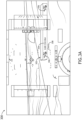
- FIG. 3A and FIG. 3B show examples of corridor graphics 302.
- the corridor graphic 302 is a dynamic inserted graphic (e.g., a 2D and/or 3D graphic (e.g., rectangular tunnel volume) inserted into a map (e.g., 3-dimensional terrain) representing the environment surrounding an aircraft).
- the corridor graphic 302 is more akin to an alert such as a pop-up window, that may be fixed in place on a screen and appear when appropriate to indicate that the aircraft is currently occupying a corridor.
- the system 100 is configured to transition from a corridor graphic 302 that is dynamically mapped to a map when approaching a corridor (e.g., imminent occupation state) and an alert when occupying a corridor (e.g., current occupation state).
- a corridor graphic 302 that is dynamically mapped to a map when approaching a corridor (e.g., imminent occupation state) and an alert when occupying a corridor (e.g., current occupation state).
- the corridor graphic 302 may include a visual symbol 306 of an aircraft on each side of a corridor label text 304.
- the corridor graphic 302 may include a horizontal alignment of the visual symbols 306 of the aircraft, and the corridor label text 304.
- the placement and/or color of the corridor graphic 302 relative to other symbols may be configured to provide a visual indication of the relative distance of the aircraft to the corridor.
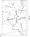
- the corridor graphic 302 may be mapped to 3-dimensional space as shown in FIG. 3A and/or 2-dimensional space as shown in FIG. 3C .
- FIG. 3A is a diagram of a display 300 for the system 100 during an imminent occupation state (e.g., when the aircraft is approaching and/or near the corridor), in accordance with one or more embodiments of the present disclosure.
- the display 145 includes a corridor graphic 302 dynamically mapped to the 3-dimensional environment and associated with the corridor.
- the corridor graphic 302 includes a corridor label text 304, such as "UAM Corridor", and one or more visual symbols 306 of an aircraft.
- the corridor graphic 302 also includes numerical text 308 indicative of the relative distance of the aircraft to the corridor.
- the processor 160 of the system 100 may be further configured to be operable to calculate the aircraft is in an imminent occupation state based on the relative distance.
- the imminent occupation state may be indicative that the aircraft is on a trajectory predicted to cause an occupation (i.e., breach) of the aircraft with the corridor.
- the processor 160 may be further operable to display numerical text 308 (e.g., 3 nautical miles, 3 nautical miles, 3 kilometers, 3 km, and/or the like) indicative of the relative distance of the aircraft to the corridor.
- FIG. 3B is a diagram of a display 310 for the system 100 during a current occupation state (e.g., when the aircraft is inside the corridor), in accordance with one or more embodiments of the present disclosure.
- the corridor graphic 302 includes a corridor label text 304, such as "UAM Corridor", and one or more visual symbols 306 of an aircraft.
- the corridor graphic 302 also includes a colored background 312 associated with the corridor graphic 302. Note, in this embodiment, the numerical text 308 indicative of the relative distance is not displayed because the result would be "0", negative, undefined, or the like.
- the processor 160 of the system 100 may be further operable (e.g., via program instructions stored on memory 170) to calculate the aircraft is in a current occupation state based on the relative distance. For example, if the relative distance indicates the aircraft is inside a boundary of a corridor. The current occupation state is indicative that the aircraft is currently occupying the corridor.
- the processor 160 of the system 100 may be further operable to display a colored background 312 associated with the corridor graphic 302.
- the colored background 312 may be used to indicate a current occupation state of the aircraft.
- the colored background 312 may be configured to be, or to change color (e.g., change to green, white, and/or the like) when the aircraft is calculated to be in the current occupation state (i.e., inside the corridor). This may provide a visual indication of the current occupation state of the aircraft.
- the green color (or the like) may quickly indicate to the user that the aircraft has entered the corridor.
- the color, and/or size (e.g., width, height, etc.) of the corridor graphic 302 as shown, or the like may be especially proficient at alerting a user compared to other symbols.
- the wide horizontal alignment of symbols 306, label 304, and background color 312 may be more easily noticed in the peripheral vision of a user compared to other graphics.
- the corridor may be any corridor known in the art.
- the corridor may include an Urban Air Mobility (UAM) corridor.
- UAM Urban Air Mobility
- FIG. 3C is a top-down diagram of a display 320 for the system 100, in accordance with one or more embodiments of the present disclosure. As shown, the display 145 is a 2-dimensional top-down view.
- a letter following a reference numeral is intended to reference an embodiment of the feature or element that may be similar, but not necessarily identical, to a previously described element or feature bearing the same reference numeral (e.g., 1, 1a, 1b).
- reference numeral e.g. 1, 1a, 1b
- Such shorthand notations are used for purposes of convenience only and should not be construed to limit the disclosure in any way unless expressly stated to the contrary.
- any reference to “in embodiments, "one embodiment” or “some embodiments” means that a particular element, feature, structure, or characteristic described in connection with the embodiment is included in at least one embodiment disclosed herein.
- the appearances of the phrase “in some embodiments” in various places in the specification are not necessarily all referring to the same embodiment, and embodiments may include one or more of the features expressly described or inherently present herein, or any combination or sub-combination of two or more such features, along with any other features which may not necessarily be expressly described or inherently present in the instant disclosure.
- embodiments of the methods disclosed herein may include one or more of the steps described herein. Further, such steps may be carried out in any desired order and two or more of the steps may be carried out simultaneously with one another. Two or more of the steps disclosed herein may be combined in a single step, and in some embodiments, one or more of the steps may be carried out as two or more sub-steps. Further, other steps or sub-steps may be carried in addition to, or as substitutes to one or more of the steps disclosed herein.
Landscapes
- Engineering & Computer Science (AREA)
- Aviation & Aerospace Engineering (AREA)
- Physics & Mathematics (AREA)
- General Physics & Mathematics (AREA)
- Traffic Control Systems (AREA)
Abstract
Description
- The present application claims the benefit of
India Provisional Patent Application 202311010416, filed February 16, 2023 - The present disclosure relates generally to displaying corridors on flight displays, and, more particularly, to displaying a graphic related to Urban Air Mobility (UAM) corridors based on a relative distance to the UAM corridors.
- According to UAM ConOPS V1.0 titled "Concept of Operations" created by the FAA, aircraft must operate under UAM specific rules, procedures, and Community based Rules (CBRS) when operating in UAM Corridors (e.g., static as well as Dynamic Delegated Corridors). Fixed wing and Unmanned Traffic Management (UTM) aircraft operate across corridors. Helicopters and UAM aircraft operate within and across corridors. When these aircrafts are outside corridors relevant ATM rules are applicable. A visual indication to remind/inform the users near corridors of relevant corridor rules or ATM/UTM rules may be desired.
- A system for graphical indication of a corridor is disclosed in accordance with one or more illustrative embodiments of the present disclosure. In one illustrative embodiment, the system may include a display and a processor. In another illustrative embodiment, the processor may be configured to receive corridor position data of a corridor and aircraft position data indicative of a position of an aircraft. In another illustrative embodiment, the processor may be configured to determine a relative distance of the aircraft in relation to the corridor based on the corridor position data and the aircraft position data. In another illustrative embodiment, the processor may be configured to display a corridor graphic associated with the corridor based on the relative distance.
- A method is disclosed in accordance with one or more illustrative embodiments of the present disclosure. In one illustrative embodiment, the method may include receiving corridor position data of a corridor and aircraft position data indicative of a position of an aircraft. In another illustrative embodiment, the method may include determining a relative distance of the aircraft in relation to the corridor based on the corridor position data and the aircraft position data. In another illustrative embodiment, the method may include displaying a corridor graphic associated with the corridor based on the relative distance.
- This Summary is provided solely as an introduction to subject matter that is fully described in the Detailed Description and Drawings. The Summary should not be considered to describe essential features nor be used to determine the scope of the Claims. Moreover, it is to be understood that both the foregoing Summary and the following Detailed Description are example and explanatory only and are not necessarily restrictive of the subject matter claimed.
- The detailed description is described with reference to the accompanying figures. The use of the same reference numbers in different instances in the description and the figures may indicate similar or identical items. Various embodiments or examples ("examples") of the present disclosure are disclosed in the following detailed description and the accompanying drawings. The drawings are not necessarily to scale. In general, operations of disclosed processes may be performed in an arbitrary order, unless otherwise provided in the claims.
-
FIG. 1 is a simplified block diagram of an aircraft including a system for graphical indication of a corridor, in accordance with one or more embodiments of the present disclosure. -
FIG. 2 is a flow diagram illustrating steps performed in a method for a graphical indication of a corridor, in accordance with one or more embodiments of the present disclosure. -
FIG. 3A is a diagram of a display for the system during an imminent occupation state, in accordance with one or more embodiments of this disclosure. -
FIG. 3B is a diagram of a display for the system during a current occupation state, in accordance with one or more embodiments of this disclosure. -
FIG. 3C is a top-down diagram of a display for the system, in accordance with one or more embodiments of this disclosure. - Before explaining one or more embodiments of the disclosure in detail, it is to be understood that the embodiments are not limited in their application to the details of construction and the arrangement of the components or steps or methodologies set forth in the following description or illustrated in the drawings. In the following detailed description of embodiments, numerous specific details may be set forth in order to provide a more thorough understanding of the disclosure. However, it will be apparent to one of ordinary skill in the art having the benefit of the instant disclosure that the embodiments disclosed herein may be practiced without some of these specific details. In other instances, well-known features may not be described in detail to avoid unnecessarily complicating the instant disclosure.
- Systems in the art are known for warning about operational areas. For example, a system for indicating an unmanned aerial vehicle (UAV) operational area is disclosed in
U.S. Patent Application Serial No. 17/101,207, filed November 23, 2020 - Referring now to the present disclosure, a system, method, and device configured to warn pilots of Urban Air Mobility (UAM) corridors are disclosed. The system includes a warning unit on-board an aircraft that receives UAM corridor data from a database, and correlates the data with aircraft position data and/or flight plan data derived from a navigation system to determine if the aircraft is approaching a known UAM corridor that may require following relevant UAM corridor rules. If a UAM corridor is identified, a graphic may be displayed to the user to increase situational awareness, such as allowing a pilot to prepare to follow relevant UAM rules. In the industry of UAM, some believe the term Advanced Air Mobility (AAM) may be a better phrase to use, due to the expansion of UAM standards, rules, and operations into non-urban settings. For example, use cases that are not necessarily urban in nature include, but are not necessarily limited to, Commercial Inter-city (Longer Range/Thin Haul), Cargo Delivery, Public Services, Private/Recreational Vehicles, and/or the like. For purposes of the present disclosure, the terms UAM and AAM may be used interchangeably.
- Broadly speaking, embodiments of the inventive concepts disclosed herein are directed to a system and method for graphical indication of a corridor relative to an aircraft. In some embodiments, two display modes may be used, one for showing a relative distance when approaching a corridor, and one for showing, generally, that the aircraft is already located in the corridor. These modes may generally improve a user's (e.g., pilot's) situational awareness by prominently being displayed in relevant areas of a display.
-
FIG. 1 is asystem 100 for a graphical indication of a corridor, in accordance with one or more embodiments of this disclosure. Thesystem 100 includes awarning unit 110, in communication with anavigation system 120, adatabase 130 and auser interface 140. Thenavigation system 120 is disposed within the aircraft. Thewarning unit 110 may additionally include, but is not limited to, acontroller 150. In embodiments, thesystem 100 is configured for an aircraft. Thesystem 100 may be configured for any aircraft known, including but not limited to, fixed-wing aircraft or rotorcraft. - In embodiments, the
warning unit 110 includes hardware, software, and/or firmware configured to execute the various functions or steps described herein. Thecontroller 150 is configured to receive, process, and transmit data within thesystem 100. Thecontroller 150 includes one ormore processors 160 configured to perform functions or steps according to program instructions stored in amemory 170. The controller may also send and receive data and signals via acommunication interface 180 to other components of thewarning unit 110 and/or thesystem 100. For example, thecontroller 150 may be configured to receive corridor position data from thedatabase 130 and aircraft position data from thenavigation system 120, process the data (e.g., determine a relative distance between the corridor position data to the aircraft position data), and display graphics (e.g., a corridor graphic associated with the corridor) to theuser interface 140. - For purposes of the present disclosure, "operable to", "configured to be operable to", and the like may mean being configured to execute software such as program instructions stored on the
memory 170, and/or the like. - The
user interface 140 may include any device capable of displaying data to a user and/or receiving data input from a user including but not limited to adisplay 145, a keyboard, a joystick, a mouse, an audio device, or a haptic device. For example, the user interface may include adisplay 145 in combination with a keyboard. In another example, the user interface may include adisplay 145 with a touchscreen. Theuser interface 140 may be physical linked with thewarning unit 110. For example, thewarning unit 110 and theuser interface 140 may be configured as single modular unit. Alternatively, theuser interface 140 may be physically detached from thewarning unit 110. For example, theuser interface 140 and thewarning unit 110 may both be on-board an aircraft, but linked only communicatively via a wireline or wireless connection. - In the case of a touchscreen display, those skilled in the art should recognize that a large number of touchscreen displays may be suitable for implementation in the present invention. For instance, the
display 145 may be integrated with a touchscreen interface, such as, but not limited to, a capacitive touchscreen, a resistive touchscreen, a surface acoustic based touchscreen, an infrared based touchscreen, or the like. In a general sense, any touchscreen display capable of integration with thesystem 100 is suitable for implementation in the present invention. - The
display 145 may include any type of display device known in the art. For example, the display may include, but are not limited to, a liquid crystal display (LCD), a light-emitting diode (LED) based display, an organic light-emitting diode (OLED) based display, an electroluminescent display (ELD), an electronic paper (E-ink) display, a plasma display panel (PDP), a display light processing (DLP) display, a cathode-ray tube (CRT), or the like. Those skilled in the art should recognize that a variety of display devices may be suitable for implementation in the present invention and the particular choice of display device may depend on a variety of factors, including, but not limited to, form factor, cost, and the like. - In some embodiments, the
user interface 140 may include adisplay 145 that is part of, or incorporated into, a primary flight display (PFD), an aircraft instrument dedicated to flight information. For example, thedisplay 145 may be configured as a picture-in-picture (PIP) display within a PFD, wherein data from thesystem 100 is displayed as the first image along with other data from different aircraft systems displayed as a second image. In another example, data from thesystem 100 is overlaid on a PFD that has incorporates data from other systems. For instance, data from thesystem 100 may appear as icons/symbols/graphics on an aircraft display that are overlaid upon, or incorporated into a virtual landscape on the PFD that corresponds to the position of the aircraft. Any configuration of PIP display or overlaid display is possible. For example, the data from thesystem 100 may be maximized to cover an entire quadrant of the PFD. In another example, thedisplay 145 may be minimized on the PFD. For the purposes of this disclosure, the PFD, and/or a portion of the PFD may be configured as adisplay 145 for thesystem 100. - In some embodiments, the
user interface 140 may include a display that is part of, or incorporated into, a map display and/or a navigation display. For example, the display may be similarly configured for use with the map display and/or navigation display as described for the PFD described herein. - In some embodiments, the
user interface 140 may include any display or type of display used onboard an aircraft. For example, the display may include a primary flight display (PFD). The display may also include any type of virtualized or augmented vision system including but not limited to a synthetic vision system (SVS), a heads-up display (HUD) a head-mounted display (HMD), a virtual reality (VR) system, a mixed reality (MR) system, an augmented reality (AR) system and an extended reality (XR) system. For example, the user interface may be an SVS display, wherein data from thesystem 100 is incorporated into the SVS display. - In embodiments, the
database 130 stores the location of a plurality of UAM corridors for vehicles operating under UAM rules. For example, the United States Federal Aviation Administration (FAA) and the United States National Aeronautics and Space Administration (NASA), as well as other industry and national and international administration agencies, are developing a safe and efficient aviation transportation system (e.g., referred to as UAM and/or AAM) that will, generally, use highly automated aircraft (e.g., automated vertical takeoff taxis, etc.) that will operate and transport passengers and/or cargo at lower altitudes (e.g., between 400 to 1500 feet, between 400 to 3,000 feet, 990 feet and below, and/or the like as decided by UAM authorities) where air traffic services are typically not provided. Low-flying drones are a growing hazard for aircraft, as their use are becoming more common in areas around airports, increasing the chance that an aircraft may collide with a drone upon takeoff or landing. One possible result of a UAM ecosystem is the creation of adatabase 130 that stores the location of corridors (e.g., areas that are likely to have UAM vehicles in the air)). Data from thisdatabase 130 may be then be shared within components of thesystem 100 allowing thesystem 100 to warn a pilot that an aircraft may be flying in or near a UAM corridor. - It is noted herein that the one or more components of the
system 100 may be communicatively coupled to the various other components of thesystem 100 in any manner known in the art. For example, the one ormore processors 160 may be communicatively coupled to each other and other components of thesystem 100 via a wireline (e.g., copper wire, fiber optic cable, and the like) or wireless connection (e.g., RF coupling, IR coupling, Wi-Fi signals, 5G signals, LoRa, Bluetooth, BLE, Zigbee, Z-wave, 6LoWPAN, NFC, WIFI Direct, GSM, LTE. NB-IOT, LTE-M, and the like). For example, thedatabase 130 may communicate with thewarning unit 110 via an RF signal. For instance, thedatabase 130 may be configured as a remote server (e.g., ground-based server) that communicates wirelessly with thewarning unit 110 via an RF signal. In another example, thedatabase 130 may be configured as an on-board server (e.g., aircraft-based server) that communicates wirelessly with thewarning unit 110 via a Bluetooth signal. In another example,database 130 may be configured as an on-board server that communicated with thewarning unit 110 via a copper wire connection. - The one or
more processors 160 may include any type of processing elements, including but not limited to integrated circuits (e.g., application specific integrated circuits (ASIC) and field programmable gate arrays (FPGA). Thecontroller 150 is not limited by the materials from which it is formed or the processing mechanisms employed therein and, as such, can be implemented via semiconductor(s) and/or transistors (e.g., using electronic integrated circuit (IC) components), and so forth. - The
communication interface 180 may be operatively configured to communicate with components of thesystem 100. For example, thecommunication interface 180 can be configured to retrieve data from thecontroller 150 or other devices (e.g., thedatabase 130, thenavigation system 120, theuser interface 140 and/or components of the warning unit 110), transmit data for storage in thememory 170, retrieve data from storage in thememory 170, and so forth. Thecommunication interface 180 may also be communicatively coupled with thecontroller 150 to facilitate data transfer between components of thesystem 100 and thecontroller 150. It should be noted that while thecommunication interface 180 is described as a component of thewarning unit 110, one or more components of thecommunication interface 180 may be implemented as external components communicatively coupled to thewarning unit 110 via a wireline and/or wireless connection. - The
memory 170 can be an example of tangible, computer-readable storage medium that provides storage functionality to store various data and/or program code associated with operation ofsystem 100 and/orcontroller 150, such as software programs and/or code segments, or other data to instruct thecontroller 150, and possibly other components of thesystem 100, to perform the functionality described herein. Thus, thememory 170 can store data, such as a program of instructions for operating the controller, a base node and its components. It should be noted that while a single memory is described, a wide variety of types of combinations of memory (e.g., tangible, non-transitory memory) may be employed. The memory can be integral with thecontroller 150, can comprise stand-alone memory, or can be a combination of both. Some examples of the memory can include removable and non-removable memory components, such as random-access memory (RAM), read-only memory (ROM), flash memory (e.g., a secure digital (SD) memory card, a mini-SD memory card, and/or a micro-SD memory card), solid-state drive (SSD) memory, magnetic memory, optical memory, universal serial bus (USB) memory devices, hard disk memory, external memory, and so forth. - The
navigation system 120 may include any componentry used for aircraft navigation. For example, thenavigation system 120 may include a flight management system (FMS). In another example, thenavigation system 120 may include a geolocation system (e.g., a global navigational satellite system (GNSS)). For instance, thenavigation system 120 may be a geolocation system configured to output an image of a map (e.g., the second image) onto a display (e.g., 2D or 3D map), the map correlating to the current position of the aircraft (e.g., aircraft position data). Thenavigation system 120 may also include one or more navigation databases. For example, the navigation system may include a navigation database (e.g., NAV DB) that stores navigational and/or geographical data. In another example, the navigation system may include an aircraft warning database (e.g., an enhanced ground proximity warning system (EGPWS) database) that provides relevant terrain and obstacle data. - In embodiments, the
warning unit 110 incorporates, or may be incorporated into, the database and/or the navigation system. For example, thewarning unit 110 may be an add-on module to anavigation system 120 giving the navigation system increased functionality (e.g., to warn of UAM corridor). In another example, thedatabase 130 may be incorporated into the warning unit 110 (e.g., thewarning unit 110 is preloaded with all corridor position data needed for the flight). In another example,database 130 and thewarning unit 110 may be incorporated into thenavigational system 120. For instance, thenavigation system 120 may include componentry and/or software that comprises the warning unit 110 (e.g., a software upgrade to thenavigation system 120 may give thenavigation system 120 the functionality of the warning unit 110) and be configured to store and utilize corridor position data. Many combinations ofwarning unit 110,navigation system 120 anddatabase 130 are possible within thesystem 100. Therefore, the above description should not be interpreted as a limitation of the present disclosure, but merely an illustration. -
FIG. 2 is a flow diagram illustrating steps performed in amethod 200 for a graphical indication of a corridor, in accordance with one or more embodiments of the present disclosure. Themethod 200 may be performed by asystem 100, such as thesystem 100 illustrated inFIG. 1 . - At
step 202, the corridor position data of a corridor is received. The corridor position data may include, but is not limited to, a location (e.g., latitude/longitude coordinates defining a boundary or center of the corridor, and/or the like) of the corridor, dimensions (e.g., 3D dimensions such as width, height, and/or length, boundary points of the corridor, and/or the like) of the corridor, and any other data associated with the corridor. An example of a corridor is shown by corridor graphic 302 inFIG. 3C . In some examples, a corridor is akin to a 3-dimensional tunnel in airspace. - At
step 204, the aircraft position data indicative of a position of an aircraft is received. The aircraft position data may include, but is not limited to, a location of the aircraft, a speed of the aircraft, a flight plan of the aircraft, and the like. - At
step 206, a relative distance of the aircraft in relation to the corridor is determined based on the corridor position data and the aircraft position data. The relative distance may be a distance between the aircraft and the corridor. For example, a program configured to calculate a 2-dimensional and/or 3-dimensional distance between the aircraft and a boundary of the corridor may be used, as are known in the art. For example, a difference between the X, Y, and Z coordinates in the units used by such a program may be calculated to generate the relative distance. For an example of a relative distance, see numerical text 308 (e.g., 3 nm) inFIG. 3A . - At
step 208, a corridor graphic 302 associated with the corridor based on the relative distance is displayed. SeeFIG. 3A for an example of a corridor graphic 302. The corridor graphic 302 may be displayed on thedisplay 145 of thesystem 100. - Note that
step 208 may include one or more sub-steps. For example, thesystem 100 may be configured to display a graphic 302 showing a state of being in a corridor when that state is reached (seeFIG. 3B ) and to show a relative location of the corridor on the display when approaching a corridor (seeFIG. 3A ). In this regard, two display modes may be used, one for showing distance when approaching a corridor, and one for showing, generally, that the aircraft is already located in a corridor. These modes may generally improve a user's (e.g., pilot's) situational awareness. -
FIG. 3A andFIG. 3B show examples ofcorridor graphics 302. InFIG. 3A , the corridor graphic 302 is a dynamic inserted graphic (e.g., a 2D and/or 3D graphic (e.g., rectangular tunnel volume) inserted into a map (e.g., 3-dimensional terrain) representing the environment surrounding an aircraft). InFIG. 3B , the corridor graphic 302 is more akin to an alert such as a pop-up window, that may be fixed in place on a screen and appear when appropriate to indicate that the aircraft is currently occupying a corridor. In some embodiments, thesystem 100 is configured to transition from a corridor graphic 302 that is dynamically mapped to a map when approaching a corridor (e.g., imminent occupation state) and an alert when occupying a corridor (e.g., current occupation state). - In some embodiments, the corridor graphic 302 may include a
visual symbol 306 of an aircraft on each side of acorridor label text 304. For example, the corridor graphic 302 may include a horizontal alignment of thevisual symbols 306 of the aircraft, and thecorridor label text 304. The placement and/or color of the corridor graphic 302 relative to other symbols may be configured to provide a visual indication of the relative distance of the aircraft to the corridor. For example, the corridor graphic 302 may be mapped to 3-dimensional space as shown inFIG. 3A and/or 2-dimensional space as shown inFIG. 3C . -
FIG. 3A is a diagram of adisplay 300 for thesystem 100 during an imminent occupation state (e.g., when the aircraft is approaching and/or near the corridor), in accordance with one or more embodiments of the present disclosure. As shown, thedisplay 145 includes a corridor graphic 302 dynamically mapped to the 3-dimensional environment and associated with the corridor. The corridor graphic 302 includes acorridor label text 304, such as "UAM Corridor", and one or morevisual symbols 306 of an aircraft. The corridor graphic 302 also includes numerical text 308 indicative of the relative distance of the aircraft to the corridor. - In some embodiments, the
processor 160 of thesystem 100 may be further configured to be operable to calculate the aircraft is in an imminent occupation state based on the relative distance. For example, the imminent occupation state may be indicative that the aircraft is on a trajectory predicted to cause an occupation (i.e., breach) of the aircraft with the corridor. When the aircraft is calculated to be in the imminent occupation state, theprocessor 160 may be further operable to display numerical text 308 (e.g., 3 nautical miles, 3 nautical miles, 3 kilometers, 3 km, and/or the like) indicative of the relative distance of the aircraft to the corridor. -
FIG. 3B is a diagram of adisplay 310 for thesystem 100 during a current occupation state (e.g., when the aircraft is inside the corridor), in accordance with one or more embodiments of the present disclosure. The corridor graphic 302 includes acorridor label text 304, such as "UAM Corridor", and one or morevisual symbols 306 of an aircraft. The corridor graphic 302 also includes acolored background 312 associated with the corridor graphic 302. Note, in this embodiment, the numerical text 308 indicative of the relative distance is not displayed because the result would be "0", negative, undefined, or the like. - In some embodiments, the
processor 160 of thesystem 100 may be further operable (e.g., via program instructions stored on memory 170) to calculate the aircraft is in a current occupation state based on the relative distance. For example, if the relative distance indicates the aircraft is inside a boundary of a corridor. The current occupation state is indicative that the aircraft is currently occupying the corridor. - In some embodiments, the
processor 160 of thesystem 100 may be further operable to display acolored background 312 associated with the corridor graphic 302. Thecolored background 312 may be used to indicate a current occupation state of the aircraft. For example, thecolored background 312 may be configured to be, or to change color (e.g., change to green, white, and/or the like) when the aircraft is calculated to be in the current occupation state (i.e., inside the corridor). This may provide a visual indication of the current occupation state of the aircraft. In other words, the green color (or the like) may quickly indicate to the user that the aircraft has entered the corridor. It is contemplated herein that the color, and/or size (e.g., width, height, etc.) of the corridor graphic 302 as shown, or the like, may be especially proficient at alerting a user compared to other symbols. For instance, the wide horizontal alignment ofsymbols 306,label 304, andbackground color 312 may be more easily noticed in the peripheral vision of a user compared to other graphics. - The corridor may be any corridor known in the art. For example, the corridor may include an Urban Air Mobility (UAM) corridor.
-
FIG. 3C is a top-down diagram of a display 320 for thesystem 100, in accordance with one or more embodiments of the present disclosure. As shown, thedisplay 145 is a 2-dimensional top-down view. - As used herein a letter following a reference numeral is intended to reference an embodiment of the feature or element that may be similar, but not necessarily identical, to a previously described element or feature bearing the same reference numeral (e.g., 1, 1a, 1b). Such shorthand notations are used for purposes of convenience only and should not be construed to limit the disclosure in any way unless expressly stated to the contrary.
- Further, unless expressly stated to the contrary, "or" refers to an inclusive or and not to an exclusive or. For example, a condition A or B is satisfied by any one of the following: A is true (or present) and B is false (or not present), A is false (or not present) and B is true (or present), and both A and B are true (or present).
- In addition, use of "a" or "an" may be employed to describe elements and components of embodiments disclosed herein. This is done merely for convenience and "a" and "an" are intended to include "one" or "at least one," and the singular also includes the plural unless it is obvious that it is meant otherwise.
- Finally, as used herein any reference to "in embodiments, "one embodiment" or "some embodiments" means that a particular element, feature, structure, or characteristic described in connection with the embodiment is included in at least one embodiment disclosed herein. The appearances of the phrase "in some embodiments" in various places in the specification are not necessarily all referring to the same embodiment, and embodiments may include one or more of the features expressly described or inherently present herein, or any combination or sub-combination of two or more such features, along with any other features which may not necessarily be expressly described or inherently present in the instant disclosure.
- It is to be understood that embodiments of the methods disclosed herein may include one or more of the steps described herein. Further, such steps may be carried out in any desired order and two or more of the steps may be carried out simultaneously with one another. Two or more of the steps disclosed herein may be combined in a single step, and in some embodiments, one or more of the steps may be carried out as two or more sub-steps. Further, other steps or sub-steps may be carried in addition to, or as substitutes to one or more of the steps disclosed herein.
- Although inventive concepts have been described with reference to the embodiments illustrated in the attached drawing figures, equivalents may be employed and substitutions made herein without departing from the scope of the claims. Components illustrated and described herein are merely examples of a system/device and components that may be used to implement embodiments of the inventive concepts and may be replaced with other devices and components without departing from the scope of the claims. Furthermore, any dimensions, degrees, and/or numerical ranges provided herein are to be understood as non-limiting examples unless otherwise specified in the claims.
Claims (15)
- A system (100) for graphical indication of a corridor, comprising:a display (145); anda processor (160) configured to be operable to:receive corridor position data of a corridor;receive aircraft position data indicative of a position of an aircraft;determine a relative distance of the aircraft in relation to the corridor based on the corridor position data and the aircraft position data; anddisplay a corridor graphic associated with the corridor based on the relative distance.
- The system of claim 1, wherein the processor (160) is further operable to:
calculate the aircraft is in an imminent occupation state based on the relative distance, wherein the imminent occupation state is indicative that the aircraft is on a trajectory predicted to cause an occupation of the aircraft with the corridor, and preferably wherein the processor is further operable to:
display, when the aircraft is calculated to be in the imminent occupation state, numerical text indicative of the relative distance of the aircraft to the corridor. - The system of claim 1 or 2, wherein the processor (160) is further operable to:
calculate the aircraft is in a current occupation state based on the relative distance, wherein the current occupation state is indicative that the aircraft is currently occupying the corridor. - The system of any preceding claim, wherein the corridor includes an Urban Air Mobility (UAM) corridor.
- The system of any preceding claim, wherein the corridor graphic includes at least one visual symbol of an aircraft.
- The system of any preceding claim, wherein the corridor graphic includes at least one corridor label text.
- The system of any preceding claim, wherein the corridor graphic includes a visual symbol of an aircraft on each side of a corridor label text, and preferably wherein the corridor graphic includes a horizontal alignment of the visual symbol of the aircraft on each side, and the corridor label text.
- The system of any preceding claim, wherein the corridor graphic includes a colored background.
- A method, comprising:receiving corridor position data of a corridor;receiving aircraft position data indicative of a position of an aircraft;determining a relative distance of the aircraft in relation to the corridor based on the corridor position data and the aircraft position data;displaying a corridor graphic associated with the corridor based on the relative distance.
- The method of claim 9, further comprising calculating the aircraft is in an imminent occupation state based on the relative distance, wherein the imminent occupation state is indicative that the aircraft is on a trajectory predicted to cause an occupation of the aircraft with the corridor, and preferably further comprising displaying, when the aircraft is calculated to be in the imminent occupation state, numerical text indicative of the relative distance of the aircraft to the corridor.
- The method of claim 9 or 10, further comprising calculating the aircraft is in a current occupation state based on the relative distance, wherein the current occupation state is indicative that the aircraft is currently occupying the corridor.
- The method of any of claims 9-11, wherein the corridor includes an Urban Air Mobility (UAM) corridor.
- The method of any of claims 9-12, further comprising displaying at least one visual symbol of an aircraft in the corridor graphic; and/or further comprising displaying at least one corridor label text in the corridor graphic.
- The method of any of claims 9-14, further comprising displaying a visual symbol of an aircraft on each side of a corridor label text in the corridor graphic, and preferably further comprising displaying a horizontal alignment of the visual symbol of the aircraft on each side, and the corridor label text in the corridor graphic.
- The method of any of claims 9-14, further comprising displaying a colored background in the corridor graphic.
Applications Claiming Priority (2)
| Application Number | Priority Date | Filing Date | Title |
|---|---|---|---|
| IN202311010416 | 2023-02-16 | ||
| US18/213,057 US12217610B2 (en) | 2023-02-16 | 2023-06-22 | UAM corridor visual indication |
Publications (1)
| Publication Number | Publication Date |
|---|---|
| EP4418236A1 true EP4418236A1 (en) | 2024-08-21 |
Family
ID=88975483
Family Applications (1)
| Application Number | Title | Priority Date | Filing Date |
|---|---|---|---|
| EP23212327.3A Pending EP4418236A1 (en) | 2023-02-16 | 2023-11-27 | Uam corridor visual indication |
Country Status (1)
| Country | Link |
|---|---|
| EP (1) | EP4418236A1 (en) |
Citations (3)
| Publication number | Priority date | Publication date | Assignee | Title |
|---|---|---|---|---|
| US20100052949A1 (en) * | 2008-08-29 | 2010-03-04 | Honeywell International Inc. | Method and system for displaying navigation corridors |
| US20180010916A1 (en) * | 2016-07-07 | 2018-01-11 | Thales | Device and method for calculating estimated navigation performance prediction |
| US20220084416A1 (en) * | 2020-09-11 | 2022-03-17 | Rockwell Collins, Inc. | Indication of uav areas in cockpit |
-
2023
- 2023-11-27 EP EP23212327.3A patent/EP4418236A1/en active Pending
Patent Citations (3)
| Publication number | Priority date | Publication date | Assignee | Title |
|---|---|---|---|---|
| US20100052949A1 (en) * | 2008-08-29 | 2010-03-04 | Honeywell International Inc. | Method and system for displaying navigation corridors |
| US20180010916A1 (en) * | 2016-07-07 | 2018-01-11 | Thales | Device and method for calculating estimated navigation performance prediction |
| US20220084416A1 (en) * | 2020-09-11 | 2022-03-17 | Rockwell Collins, Inc. | Indication of uav areas in cockpit |
Similar Documents
| Publication | Publication Date | Title |
|---|---|---|
| US12217610B2 (en) | UAM corridor visual indication | |
| US8160755B2 (en) | Displaying air traffic symbology based on relative importance | |
| US7212216B2 (en) | Perspective view primary flight display with terrain-tracing lines and method | |
| US7917289B2 (en) | Perspective view primary flight display system and method with range lines | |
| US8903655B2 (en) | Method and system for displaying emphasized aircraft taxi landmarks | |
| US8843255B2 (en) | Methods for displaying aircraft procedure information | |
| US8209122B2 (en) | System and method for rendering visible features of a target location on a synthetic flight display | |
| EP3509052B1 (en) | Safe speed advisories for flight deck interval management (fim) paired approach (pa) systems | |
| EP2244240B1 (en) | Methods and systems for displaying a vertical profile for an aircraft procedure with nonuniform scaling | |
| US8736465B2 (en) | Aircraft traffic display | |
| US7295901B1 (en) | System and method for indicating a position of an aircraft to a user | |
| EP2431960A2 (en) | Ground navigational display, system and method displaying buildings in three-dimensions | |
| EP2919219B1 (en) | System and method for identifying runway position during an intersection takeoff | |
| EP2159545A1 (en) | Method and system for displaying navigation corridors | |
| US20100148990A1 (en) | System and method for selectively displaying terminal procedure data | |
| US7477985B2 (en) | Method and apparatus for displaying TCAS information with enhanced vertical situational awareness | |
| US20220084416A1 (en) | Indication of uav areas in cockpit | |
| EP2980772A1 (en) | System and method for automatically identifying displayed atc mentioned traffic | |
| EP2801964A1 (en) | System and method for displaying rate-of-climb on an avionics vertical speed indicator | |
| US20250191477A1 (en) | Roaas runway alignment indications on airport moving map | |
| EP3968311A1 (en) | Indication of uav areas in cockpit | |
| US12555486B2 (en) | Augmented reality taxi assistant | |
| EP4513469A1 (en) | Method and system for taxi assist path generation based on guidance lines of an airport |
Legal Events
| Date | Code | Title | Description |
|---|---|---|---|
| PUAI | Public reference made under article 153(3) epc to a published international application that has entered the european phase |
Free format text: ORIGINAL CODE: 0009012 |
|
| STAA | Information on the status of an ep patent application or granted ep patent |
Free format text: STATUS: THE APPLICATION HAS BEEN PUBLISHED |
|
| AK | Designated contracting states |
Kind code of ref document: A1 Designated state(s): AL AT BE BG CH CY CZ DE DK EE ES FI FR GB GR HR HU IE IS IT LI LT LU LV MC ME MK MT NL NO PL PT RO RS SE SI SK SM TR |
|
| STAA | Information on the status of an ep patent application or granted ep patent |
Free format text: STATUS: REQUEST FOR EXAMINATION WAS MADE |
|
| 17P | Request for examination filed |
Effective date: 20250220 |
|
| REG | Reference to a national code |
Ref country code: DE Ref legal event code: R079 Free format text: PREVIOUS MAIN CLASS: G08G0005000000 Ipc: G08G0005210000 |
|
| GRAP | Despatch of communication of intention to grant a patent |
Free format text: ORIGINAL CODE: EPIDOSNIGR1 |
|
| STAA | Information on the status of an ep patent application or granted ep patent |
Free format text: STATUS: GRANT OF PATENT IS INTENDED |
|
| RIC1 | Information provided on ipc code assigned before grant |
Ipc: G08G 5/21 20250101AFI20260310BHEP Ipc: G08G 5/53 20250101ALI20260310BHEP Ipc: G08G 5/55 20250101ALI20260310BHEP Ipc: G08G 5/23 20250101ALI20260310BHEP Ipc: G08G 5/59 20250101ALI20260310BHEP Ipc: G08G 5/90 20250101ALI20260310BHEP Ipc: G08G 5/57 20250101ALN20260310BHEP |
|
| RIC1 | Information provided on ipc code assigned before grant |
Ipc: G08G 5/21 20250101AFI20260318BHEP Ipc: G08G 5/53 20250101ALI20260318BHEP Ipc: G08G 5/55 20250101ALI20260318BHEP Ipc: G08G 5/23 20250101ALI20260318BHEP Ipc: G08G 5/59 20250101ALI20260318BHEP Ipc: G08G 5/90 20250101ALI20260318BHEP Ipc: G08G 5/57 20250101ALN20260318BHEP |
|
| INTG | Intention to grant announced |
Effective date: 20260331 |