EP4418218A1 - Virtual overlays in camera mirror systems - Google Patents
Virtual overlays in camera mirror systems Download PDFInfo
- Publication number
- EP4418218A1 EP4418218A1 EP23156598.7A EP23156598A EP4418218A1 EP 4418218 A1 EP4418218 A1 EP 4418218A1 EP 23156598 A EP23156598 A EP 23156598A EP 4418218 A1 EP4418218 A1 EP 4418218A1
- Authority
- EP
- European Patent Office
- Prior art keywords
- processor device
- predetermined
- subsequent
- initial
- camera
- Prior art date
- Legal status (The legal status is an assumption and is not a legal conclusion. Google has not performed a legal analysis and makes no representation as to the accuracy of the status listed.)
- Pending
Links
Images




Classifications
-
- B—PERFORMING OPERATIONS; TRANSPORTING
- B60—VEHICLES IN GENERAL
- B60R—VEHICLES, VEHICLE FITTINGS, OR VEHICLE PARTS, NOT OTHERWISE PROVIDED FOR
- B60R1/00—Optical viewing arrangements; Real-time viewing arrangements for drivers or passengers using optical image capturing systems, e.g. cameras or video systems specially adapted for use in or on vehicles
- B60R1/20—Real-time viewing arrangements for drivers or passengers using optical image capturing systems, e.g. cameras or video systems specially adapted for use in or on vehicles
- B60R1/22—Real-time viewing arrangements for drivers or passengers using optical image capturing systems, e.g. cameras or video systems specially adapted for use in or on vehicles for viewing an area outside the vehicle, e.g. the exterior of the vehicle
- B60R1/28—Real-time viewing arrangements for drivers or passengers using optical image capturing systems, e.g. cameras or video systems specially adapted for use in or on vehicles for viewing an area outside the vehicle, e.g. the exterior of the vehicle with an adjustable field of view
-
- G—PHYSICS
- G06—COMPUTING OR CALCULATING; COUNTING
- G06T—IMAGE DATA PROCESSING OR GENERATION, IN GENERAL
- G06T7/00—Image analysis
- G06T7/80—Analysis of captured images to determine intrinsic or extrinsic camera parameters, i.e. camera calibration
-
- G—PHYSICS
- G06—COMPUTING OR CALCULATING; COUNTING
- G06V—IMAGE OR VIDEO RECOGNITION OR UNDERSTANDING
- G06V20/00—Scenes; Scene-specific elements
- G06V20/50—Context or environment of the image
- G06V20/56—Context or environment of the image exterior to a vehicle by using sensors mounted on the vehicle
-
- B—PERFORMING OPERATIONS; TRANSPORTING
- B60—VEHICLES IN GENERAL
- B60R—VEHICLES, VEHICLE FITTINGS, OR VEHICLE PARTS, NOT OTHERWISE PROVIDED FOR
- B60R2300/00—Details of viewing arrangements using cameras and displays, specially adapted for use in a vehicle
- B60R2300/30—Details of viewing arrangements using cameras and displays, specially adapted for use in a vehicle characterised by the type of image processing
- B60R2300/307—Details of viewing arrangements using cameras and displays, specially adapted for use in a vehicle characterised by the type of image processing virtually distinguishing relevant parts of a scene from the background of the scene
- B60R2300/308—Details of viewing arrangements using cameras and displays, specially adapted for use in a vehicle characterised by the type of image processing virtually distinguishing relevant parts of a scene from the background of the scene by overlaying the real scene, e.g. through a head-up display on the windscreen
-
- B—PERFORMING OPERATIONS; TRANSPORTING
- B62—LAND VEHICLES FOR TRAVELLING OTHERWISE THAN ON RAILS
- B62D—MOTOR VEHICLES; TRAILERS
- B62D15/00—Steering not otherwise provided for
- B62D15/02—Steering position indicators ; Steering position determination; Steering aids
- B62D15/027—Parking aids, e.g. instruction means
-
- G—PHYSICS
- G06—COMPUTING OR CALCULATING; COUNTING
- G06V—IMAGE OR VIDEO RECOGNITION OR UNDERSTANDING
- G06V2201/00—Indexing scheme relating to image or video recognition or understanding
- G06V2201/07—Target detection
Definitions
- the disclosure relates generally to camera mirror systems for vehicles.
- the disclosure relates to virtual overlays in camera mirror systems.
- the disclosure can be applied in heavy-duty vehicles, such as trucks, buses, and construction equipment.
- trucks, buses, and construction equipment such as trucks, buses, and construction equipment.
- Camera mirror systems are becoming more common and are used for assisting a driver of a vehicle to get a better view of the road and objects behind the host vehicle.
- Adding distance lines may be added as overlays in a screen view of the captured field of view of the camera. These lines can assist the driver in judging the location of the host vehicle in view of other vehicles or objects behind the host vehicle. This is particularly useful for vehicles with trailers. However, such features may require preexisting knowledge of the trailer and associated information.
- a computer system comprising a processor device configured to: receive initial image data from at least one camera of a vehicle; detect, in the initial image data, at least one predetermined target mounted to a trailer of the vehicle, the at least one predetermined target at an initial position and initial angular orientation relative to the at least one camera; position a virtual assist feature in a first position and a first angular orientation in a display view based on the initial position and the initial angular orientation of the at least one predetermined target, detect, in subsequent image data, the at least one predetermined target at a subsequent position and a subsequent angular orientation relative to the at least one camera, and adjust the virtual assist feature in the display view based on the subsequent position and the subsequent angular orientation relative to the at least one camera.
- the first aspect of the disclosure may seek to automatically adjust a virtual assist feature regardless of the trailer type and thereby improve diversity handling of trailers.
- a technical benefit may include automatic adjustment of virtual assist features for assisting drivers.
- a computer-implemented method comprising: receiving, by a processor device of a computer system, initial image data from at least one camera of a vehicle, detecting, by the processor device, in the initial image data, at least one predetermined target mounted to a trailer of the vehicle, the at least one predetermined target at an initial position and initial angular orientation relative to the at least one camera; positioning, by a processor device, a virtual assist feature in a first position and a first angular orientation in a display view based on and the initial position and initial angular orientation of the at least one predetermined target, detecting, by the processor device, in subsequent image data, the at least one predetermined target at a subsequent position and a subsequent angular orientation relative to the at least one camera, and adjusting by the processor device, the virtual assist feature in the display view based on the subsequent position and the subsequent angular orientation relative to the at least one camera.
- the second aspect of the disclosure may seek to provide a method to adjust a virtual assist feature regardless of the trailer type and thereby improve diversity handling of trailers.
- a technical benefit may include automatic adjustment of virtual assist features for assisting drivers.
- the initial position and initial angular orientation, and the subsequent position and the subsequent angular orientation of the at least one predetermined target may be determined based on a predetermined transformation function from position and angular orientation relative to the at least one camera, to position and angular orientation in the display view.
- a technical benefit may include that the transfer function may provide improved consistency in the transfer from position and angular orientation in the camera field of view to the display view.
- the method may comprise: detecting, by the processor device, a predetermined calibration marker with known dimensions and at a known location relative the camera, and determining, by the processor device, the predetermined transformation function based at least on the known dimensions and the known location of the predetermined calibration marker and based on the pixel layout of the display view, the predetermined transformation function representing a rotation-translation transformation from the camera field of view to the display view.
- a technical benefit may include that the accuracy in positioning of the virtual assist feature in the display view is improved with this calibration procedure.
- the predetermined markers may have a predetermined size and a predetermined shape.
- a technical benefit may include higher accuracy calibration and marker detection.
- detecting the predetermined marker in the image data may be based on image analysis.
- a technical benefit may include that the camera that detect light in the visual spectrum may be used that provides for a clear viewable display view for a user.
- the camera may include color sensitive pixels.
- the predetermined markers have layouts distinguishable from each other. That is, the predetermined markers are unique, which advantageously provides for assigning unique virtual assist features to different predetermined markers.
- the method may further comprise positioning, by the processor device, a second virtual assist feature in a second position and second angular orientation in the display view, and adjusting, by the processor device, each of the virtual assist features in the at least one display view according to the subsequent position and subsequent angular orientation.
- a technical benefit may include that more complex and informative virtual assist features may be provided.
- the method may further comprise detecting, by the processor device, a set of predetermined targets mounted on the trailer at or near corners of the trailer, calculating, by the processor device, dimensions of the trailer based on differences in initial positions or subsequent positions for the set of predetermined targets, and providing, by the processor device, a message including the calculated dimensions of the trailer to a user interface of the vehicle or to a memory storage.
- a technical benefit may include that the dimensions of the trailer can be provided even when a new trailer is used, without the need for recalibration. Thus, providing trailer dimensions to a user for a new trailer is facilitated.
- the method may include positioning, by the processor device, a three-dimensional virtual assist feature mapped into the display view.
- a three-dimensional virtual assist feature may advantageously provide even more accurate and informative virtual assist features.
- the method may comprise generating, by the processor device, at least one virtual assist feature offset from the outline of the trailer in the display view.
- a technical benefit may include that so-called end-of-vehicle lines that indicate trailer length may be provided.
- the method may comprise detecting, by the processor device, a new predetermined target in the display view, and positioning, by the processor device, a new virtual assist feature in the display view.
- a technical benefit may be that the number of targets and thereby possible virtual assist features are easily expanded.
- image data may be received from two rearward facing cameras arranged on opposite sides of a cab of the vehicle, and predetermined targets mounted on two sides of the trailer are detected, wherein virtual assist features are positioned and adjusted in the two display views.
- a technical benefit may be that virtual assist features for both sides of the vehicle are provided.
- the method may comprise detecting, by the processor device, in the image data, at least two predetermined targets; positioning, by the processor device, the virtual assist feature in the display view reaching between the first positions of each of the at least two detected predetermined targets, and adjusting each of the first positions and first angular orientations according to the respective subsequent position and subsequent angular orientation.
- a technical benefit may be more complex virtual assist features are enabled by combining the detected locations of multiple predetermined targets.
- the method may include retrieving, by the processor device, the virtual assist feature from a library of predetermined virtual assist features, and positioning, by the processor device, the retrieved virtual assist feature in the first position and the first angular orientation in the display view.
- a technical benefit may be that the required processing power by the processor device is reduced by having predetermined virtual assist features.
- the method may comprise: detecting, by the processor device, in the initial image data, two or more of the at least one predetermined target, at initial positions and initial angular orientations relative to the at least one camera based on image analysis, the predetermined markers have a predetermined shape and are distinguishable from each other; positioning, by a processor device, a virtual assist feature for each of the predetermined markers in respective first positions and first angular orientations in a display view determined from the initial positions and initial angular orientations and a predetermined transformation function configured to transform a location in the camera field of view to pixels in the display view, detecting, by the processor device, in subsequent image data, the at least two predetermined targets at subsequent positions and subsequent angular orientations relative to the at least one camera based on image analysis, adjusting by the processor device, the virtual assist features in the at least one display view according to the subsequent positions and subsequent angular orientations relative to the at least one camera and the predetermined transformation function, and in each of the initial image data and the and subsequent image data, calculating,
- a vehicle comprising the processor device to perform the method of any of the examples of the second aspect.
- control system comprising one or more control units configured to perform the method of any of the examples of the second aspect.
- Non-transitory computer-readable storage medium comprising instructions, which when executed by the processor device, cause the processor device to perform the method of any of the examples of the second aspect.
- Vehicles such as trucks may be equipped with support functions and apparatuses to display the trailer on a screen with overlays to assist the driver in location of the trailer in relation to surrounding objects and other vehicles.
- support functions typically require size information about the trailer to place the overlay correctly, thus, switching to a new trailer requires re-calibrating the overlay.
- the graphics of the overlay is typically of very simple nature and may not always give adequate support for the user.
- Using predetermined markers may address at least some of the drawbacks of prior art.
- FIG. 1 is a truck 1 according to one example vehicle.
- the truck 1 comprises a camera 2 facing with its field of view 3 in the rear direction.
- the truck 1 further comprises a processing device 5.
- the truck 1 is attached to a trailer 40 comprising a cabin 6 having a side surface 6a facing in a transversal direction and a front surface 6b and a rear surface 6c.
- the trailer 40further includes a chassis 4 supporting the cabin and being carried by wheels 8.
- a predetermined target 26 is attached to the cabin of the trailer.
- the predetermined marker 26 may be printed on a sheet material and attached to the cabin 6 of the trailer 40 using an adhesive.
- the predetermined target 26 includes a distinguishable pattern that is detectable by the camera 2. In case more than one predetermined target 26 is used they are of the same type and size, but distinguishable from each other. Generally, the predetermined target 26 may be a fiducial marker typically used for augmented reality system to combine the real-world image with a virtual feature. A typical size of the predetermined target 26 is about 200 mm by 200 mm.
- FIG. 2 is an exemplary system diagram of a computer system according 7 to one example.
- the computer system 7 comprises a processor device 5 configured to receive a video stream 13 comprising image frames, here exemplified as image frames 15a-c, such as from a camera 2.
- the camera 2 comprises optics 9 and a pixel array 11 of light sensitive pixels that convert light to electric signals for capturing an image. Further, as applicable, the camera 2 may include optical filters and other electrical and/or optical components.
- the camera 2 may comprise color sensitive pixels detecting incident light, where the pixels may be configured to detect light in the visual spectrum.
- the processor device 5 is configured to operate an image pipeline 17 for performing various digital image processing of the image frames 15a-c, such as denoising, image scaling, data compression, and framerate conversion, to mention a few examples.
- the image pipeline 17 provides a final video feed 20 to a display 22.
- the processing device 5 receives, via hardwired or wireless data communication, initial image data from at least one camera 2 of a vehicle.
- the initial image data may be one or more of the image frames 15a-c of the video stream 13.
- the image frame 15a represents the initial image data.
- the processing device 5 is configured to detect, in the initial image data, at least one predetermined target 26 mounted to a trailer of the vehicle.
- the at least one predetermined target 26 being at an initial position 18a and initial angular orientation 19a relative to the at least one camera 2.
- the processing device 5 applies software components 24 for recognizing, locating and estimating a pose of the predetermined target 26 in the view of the camera.
- the predetermined markers are so-called Aruco markers.
- Aruco markers include a distinguishable pattern that is recognizable by software components and are per se known.
- the processing device 5 is configured to position a virtual assist feature 28 in a first position 29a and a first angular orientation 30a in a display view 23 provided by the display 22, based on the initial position 18a and the initial angular orientation 19a of the at least one predetermined target 26.
- no prior information or data regarding the trailer 40 is needed for generating the overlay including the virtual assist feature 28 in the display view 23.
- the system 7 need only detect the predetermined target 26 in the image data 15a-c to be able to produce the virtual assist feature 28 in the display view 23. This further provides for more efficient processing for generating and adjusting the overlay since reduced amount of data is needed for the overlay generation.
- the virtual assist feature 28 is a virtual overlay in the display view 23 of the trailer 40 and may be of various kinds.
- the virtual assist feature 28 may be a line or several lines.
- the virtual assist feature 28 may be two-dimensional or even three-dimensional object overlayed in the display view 23.
- the virtual assist feature 28 may be used to outline the trailer 40, or to indicate the rear end of the trailer 40, or the height of the trailer 40.
- the processor device 5 detects the at least one predetermined target 26 at a subsequent position 18b and a subsequent angular orientation 19b relative to the at least one camera 2.
- the position and angular orientation of the predetermined target 26 has changed relative to the camera 2.
- the processor device 5 may apply the software components 24 to each of the image frames 15a-c of the video stream, and continuously detect the position and angular orientation of the predetermined marker 26.
- the virtual assist feature 28 is adjusted by the processor device 5 based on the subsequent position and the subsequent angular orientation relative to the at least one camera 2.
- the processor device has access to a non-volatile memory storage device 27 storing a library 29 of virtual assist features.
- the processor device 5 may retrieve the virtual assist feature from the library 29 stored in the memory storage device 27.
- the retrieved virtual assist feature is positioned, by the processor device, in the first position 29a and the first angular orientation 30a in the display view 23.
- the initial position 18a and initial angular orientation 19a, and the subsequent position 18b and the subsequent angular orientation 19b of the at least one predetermined target are determined based on a predetermined transformation function 32 from position and angular orientation relative to the at least one camera 2, to position and angular orientation in the display view 23.
- the transformation function 32 is configured to transfer coordinates in the camera view to coordinates in the display view.
- the processor device 5 may be connected to a user interface 33 and may be configured to provide a message M to the user interface, for example indicating calculated dimensions of a trailer.
- FIG. 3 conceptually illustrates a camera 2 located at a known distance D from predetermined calibration marker 34 with known dimensions and at a known location relative the camera 2.
- the transformation function 32 may be determined, by the processor device 5, based at least on the known dimensions and the known location of the predetermined calibration marker 34, and based on the pixel layout 36 of the display.
- the predetermined transformation function 32 representing a rotation-translation transformation from the camera field of view to the display view.
- FIG. 4 is a flow-chart of an exemplary method to adjust a virtual assist feature in a display view.
- step S102 receiving, by a processor device 5 of a computer system 7, initial image data 15a from at least one camera 2 of a vehicle 1.
- step S104 detecting, by the processor device 5, in the initial image data 15a, at least one predetermined target 26 mounted to a trailer 40 of the vehicle 1, the at least one predetermined target 28 at an initial position 18a and initial angular orientation 19a relative to the at least one camera 2.
- the predetermined markers 26 may have a predetermined size and a predetermined shape. This advantageously allows for accurate depth perception and pose or angular orientation detection of the predetermined markers 26 in the display view 23.
- the predetermined markers 26 have layouts distinguishable from each other, which enables more accurate distinction between the predetermined markers, when positioning virtual assist features 28 based on more than one predetermined marker 26.
- detecting the predetermined marker 26 in the image data 15a-c may be based on image analysis. This further implies that the camera 2 may be camera with color sensitive pixels 11, thus not an IR-camera, or equipment employing LiDAR, or RADAR technology.
- step S106 positioning, by the processor device 5, a virtual assist feature 28 in a first position 29a and a first angular orientation 30a in a display view 23 based on the initial position 18a and initial angular orientation 19a of the at least one predetermined marker 26.
- the virtual assist feature 28 may be a one-dimensional virtual assist feature, or a two-dimensional virtual assist feature, or in some examples a three-dimensional virtual assist feature that is mapped into the display view 23.
- step S108 detecting, by the processor device 5, in subsequent image data 15c, the at least one predetermined target 26 at a subsequent position 18b and a subsequent angular orientation 19b relative to the at least one camera 2.
- step S110 adjusting, by the processor device 5, the virtual assist feature in the display view based on the subsequent position and the subsequent angular orientation relative to the at least one camera.
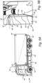
- FIG. 5A illustrates a vehicle in the form of a truck 1 with a trailer 40.
- a set of predetermined markers 42, 44, 46, 48 are attached on the side of the trailer 40.
- predetermined markers 50, 52 are attached to the forward-looking side of the trailer 40 facing the cab 54 of the vehicle.
- the predetermined markers 42, 44, 46, 48, 50, 52 may be Aruco markers.
- the rearward facing camera 2 captures a video stream shown on a display in the vehicle cab 54 as a display view 56 show in FIG. 5B .
- the predetermined markers 42, 44, 46, 48, 50, 52 are visible attached to the trailer 40.
- the processing device 5 has thus detected predetermined markers 42, 44, 46, 48, 50, 52 in the video stream and has positioned more than one virtual assist feature in the display view 56.
- the processing device has positioned a first virtual assist feature 58 along the height of the trailer 40 in z-dimension.
- the predetermined marker 44 may have been detected, and the virtual assist feature 58 is positioned in a position and angular orientation based on the position and angular orientation of the predetermined target 44.
- a set of virtual assist features 58, 62, 63, 64 are used to indicate the outline of the trailer 40.
- the virtual assist features 58, 62, 63, 64 which are lines between the positions of the detected predetermined markers 42, 44, 46, 48, provide assisting lines in the display view that indicate the outline of the trailer 40, in this example, the perimeter of the side 6a is outlined.
- the processor device has detected a second predetermined target 46 and position a second virtual assist feature 60 in a second position and second angular orientation in the display view 56. It is further noted that the virtual assist feature 60 reaches away from the trailer 40 to an offset location from the outline of the trailer 40 in the display view 56. This offset virtual assist feature 60 provides improved detectability of the rear end of the trailer 40 for a user, when the corresponding predetermined marker 46 is attached at the rear end.
- the processor device may detect the new predetermined target 50 in the display view 56. That is, with a pre-calibrated system, for example with the transfer function 32 determined, the processor device 5 may automatically detect a new marker.
- the processor device positions a new virtual assist feature 69 in the display view 56.
- FIG. 6A illustrates a display view captured by a rearward facing camera of a vehicle.
- a processor device detects at least one predetermined marker 42, 44, 46, 48, 50, 52.
- the processor device positions virtual assist features, e.g., virtual assist features 60 and 62, in positions and angular orientations based on the initial position and initial angular orientation of the at least one predetermined target, in this example, the predetermined targets 46 and 44 respectively.
- virtual assist features e.g., virtual assist features 60 and 62
- subsequent image data 57 represented in the display view 56 shown in FIG. 6B
- the processor device detects the predetermined targets 46 and 44.
- the trailer 40 has moved with respect to the camera, here exemplified as the vehicle and trailer turning and reversing towards opening 25.
- the predetermined markers 42, 44, 46, 48, 50, 52 are attached to and thereby fixed relative trailer 40. Consequently, the predetermined markers 42, 44, 46, 48, 50, 52 move in relation to the camera mounted on the vehicle pulling the trailer 40.
- the processor device detects the at least one predetermined target 42, 44, 46, 48, 50, 52 at a subsequent position and a subsequent angular orientation relative to the at least one camera.
- the virtual assist features 60, 62 are adjusted, by the processor device, in the at least one display view 56 according to the subsequent position and subsequent angular orientation. That is, the virtual assist features 60, 62 maintain their relative positions and angular rotations with respect to the respective predetermined targets 46 and 44 as the trailer 40 moves.
- the processor device may position and adjust individual virtual assist features for the predetermined targets 42, 44, 46, 48, 50, 52.
- the processor device may detect at least two predetermined targets, e.g., predetermined targets 46 and 48
- the by the processor device may position a virtual assist feature 64 in the display view reaching between the first positions of each of the at least two detected predetermined targets as shown in FIG. 6A .
- the processor device adjusts each of the first positions and first angular orientations according to the respective subsequent position and subsequent angular orientation of the predetermined targets 46 and 48, as shown in FIG. 6B .
- the adjustment provides for that the virtual assist feature 64 maintain between the predetermined targets 46 and 48 also in the later display view 57.
- the virtual assist feature 62 between predetermined targets 42 and 44 and the virtual assist feature 58 between predetermined targets 44 and 46 maintain between their respective predetermined targets also in the later display view 57.
- the virtual assist features 58, 62, 63, and 64 indicate the outline of the trailer side.
- the predetermined markers 42, 44, 46, and 48 are mounted at corners of the trailer 40.
- the processor device detects the set of predetermined targets 42, 44, 46, and 48. This allows the processor device to calculate dimensions, height h and length 1, of the trailer 40 based on differences in initial positions or subsequent positions for the set of predetermined targets.
- the processor device may provide a message including the calculated dimensions of the trailer to a user interface of the vehicle or to a memory storage.
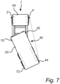
- Fig. 7 is a top-view of a vehicle 1 having a trailer 40 on which predetermined targets 42 and 44 are mounted on one side of the trailer 40, being the same side as a first rearward facing camera 4.
- a second rearward facing camera 2 is located on the transversally opposite side of the vehicle cab 54.
- the second rearward facing camera 2 is arranged to capture images of predetermined targets 70, 72.
- image data is received from two rearward facing cameras and predetermined targets 42, 44, 70, 72 on the two sides of the trailer 40 are detected by the processor device. This provides for virtual assist features being positioned and adjusted in the two display views.
- the method may comprise: detecting, by the processor device, in the initial image data, two or more of the at least one predetermined target, at initial positions and initial angular orientations relative to the at least one camera based on image analysis, the predetermined markers have a predetermined shape and are distinguishable from each other; positioning, by a processor device, a virtual assist feature for each of the predetermined markers in respective first positions and first angular orientations in a display view determined from the initial positions and initial angular orientations and a predetermined transformation function configured to transform a location in the camera field of view to pixels in the display view, detecting, by the processor device, in subsequent image data, the at least two predetermined targets at subsequent positions and subsequent angular orientations relative to the at least one camera based on image analysis, adjusting by the processor device, the virtual assist features in the at least one display view according to the subsequent positions and subsequent angular orientations relative to the at least one camera and the predetermined transformation function, and in each of the initial image data and the and subsequent image data, calculating,
- FIG. 8 is another view of FIG. 2 , according to another example.
- FIG. 8 is a view of a computer system 7 comprising a processor device 5 configured to: receive initial image data 15a from at least one camera 2 of a vehicle, detect, in the initial image data 15a, at least one predetermined target mounted to a trailer of the vehicle, the at least one predetermined target at an initial position and initial angular orientation relative to the at least one camera 2; position a virtual assist feature 28 in a first position and a first angular orientation in a display view 23 based on the initial position and the initial angular orientation of the at least one predetermined target, detect, in subsequent image data 15b, the at least one predetermined target at a subsequent position and a subsequent angular orientation relative to the at least one camera, and adjust the virtual assist feature 28 in the display view 23 based on the subsequent position and the subsequent angular orientation relative to the at least one camera.
- FIG. 9 is a flow chart of a method according to one example.
- step S 102 receiving by a processor device of a computer system, initial image data from at least one camera of a vehicle.
- step S 104 detecting, by the processor device, in the initial image data, at least one predetermined target mounted to a trailer of the vehicle, the at least one predetermined target at an initial position and initial angular orientation relative to the at least one camera.
- step S 106 positioning, by the processor device, a virtual assist feature in a first position and a first angular orientation in a display view based on the initial position and initial angular orientation of the at least one predetermined target.
- step S108 detecting, by the processor device, in subsequent image data, the at least one predetermined target at a subsequent position and a subsequent angular orientation relative to the at least one camera.
- step S 110 adjusting, by the processor device, the virtual assist feature in the display view based on the subsequent position and the subsequent angular orientation relative to the at least one camera.
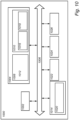
- FIG. 10 is a schematic diagram of a computer system 1000 for implementing examples disclosed herein.
- the computer system 1000 is adapted to execute instructions from a computer-readable medium to perform these and/or any of the functions or processing described herein.
- the computer system 1000 may be connected (e.g., networked) to other machines in a LAN, an intranet, an extranet, or the Internet. While only a single device is illustrated, the computer system 1000 may include any collection of devices that individually or jointly execute a set (or multiple sets) of instructions to perform any one or more of the methodologies discussed herein.
- any reference in the disclosure and/or claims to a computer system, computing system, computer device, computing device, control system, control unit, electronic control unit (ECU), processor device, etc. includes reference to one or more such devices to individually or jointly execute a set (or multiple sets) of instructions to perform any one or more of the methodologies discussed herein.
- control system may include a single control unit or a plurality of control units connected or otherwise communicatively coupled to each other, such that any performed function may be distributed between the control units as desired.
- such devices may communicate with each other or other devices by various system architectures, such as directly or via a Controller Area Network (CAN) bus, etc.
- CAN Controller Area Network
- the computer system 1000 may comprise at least one computing device or electronic device capable of including firmware, hardware, and/or executing software instructions to implement the functionality described herein.
- the computer system 1000 may include a processor device 1002 (may also be referred to as a control unit), a memory 1004, and a system bus 1006.
- the computer system 1000 may include at least one computing device having the processor device 1002.
- the system bus 1006 provides an interface for system components including, but not limited to, the memory 1004 and the processor device 1002.
- the processor device 1002 may include any number of hardware components for conducting data or signal processing or for executing computer code stored in memory 1004.
- the processor device 1002 may, for example, include a general-purpose processor, an application specific processor, a Digital Signal Processor (DSP), an Application Specific Integrated Circuit (ASIC), a Field Programmable Gate Array (FPGA), a circuit containing processing components, a group of distributed processing components, a group of distributed computers configured for processing, or other programmable logic device, discrete gate or transistor logic, discrete hardware components, or any combination thereof designed to perform the functions described herein.
- the processor device may further include computer executable code that controls operation of the programmable device.
- the system bus 1006 may be any of several types of bus structures that may further interconnect to a memory bus (with or without a memory controller), a peripheral bus, and/or a local bus using any of a variety of bus architectures.
- the memory 1004 may be one or more devices for storing data and/or computer code for completing or facilitating methods described herein.
- the memory 1004 may include database components, object code components, script components, or other types of information structure for supporting the various activities herein. Any distributed or local memory device may be utilized with the systems and methods of this description.
- the memory 1004 may be communicably connected to the processor device 1002 (e.g., via a circuit or any other wired, wireless, or network connection) and may include computer code for executing one or more processes described herein.
- the memory 1004 may include non-volatile memory 1008 (e.g., read-only memory (ROM), erasable programmable read-only memory (EPROM), electrically erasable programmable read-only memory (EEPROM), etc.), and volatile memory 1010 (e.g., random-access memory (RAM)), or any other medium which can be used to carry or store desired program code in the form of machine-executable instructions or data structures and which can be accessed by a computer or other machine with a processor device 1002.
- a basic input/output system (BIOS) 1012 may be stored in the non-volatile memory 1008 and can include the basic routines that help to transfer information between elements within the computer system 1000.
- BIOS basic input/output system
- the computer system 1000 may further include or be coupled to a non-transitory computer-readable storage medium such as the storage device 1014, which may comprise, for example, an internal or external hard disk drive (HDD) (e.g., enhanced integrated drive electronics (EIDE) or serial advanced technology attachment (SATA)), HDD (e.g., EIDE or SATA) for storage, flash memory, or the like.
- HDD enhanced integrated drive electronics
- SATA serial advanced technology attachment
- the storage device 1014 and other drives associated with computer-readable media and computer-usable media may provide non-volatile storage of data, data structures, computer-executable instructions, and the like.
- a number of modules can be implemented as software and/or hard-coded in circuitry to implement the functionality described herein in whole or in part.
- the modules may be stored in the storage device 1014 and/or in the volatile memory 1010, which may include an operating system 1016 and/or one or more program modules 1018. All or a portion of the examples disclosed herein may be implemented as a computer program product 1020 stored on a transitory or non-transitory computer-usable or computer-readable storage medium (e.g., single medium or multiple media), such as the storage device 1014, which includes complex programming instructions (e.g., complex computer-readable program code) to cause the processor device 1002 to carry out the steps described herein.
- the computer-readable program code can comprise software instructions for implementing the functionality of the examples described herein when executed by the processor device 1002.
- the processor device 1002 may serve as a controller or control system for the computer system 1000 that is to implement the functionality described herein.
- the computer system 1000 also may include an input device interface 1022 (e.g., input device interface and/or output device interface).
- the input device interface 1022 may be configured to receive input and selections to be communicated to the computer system 1000 when executing instructions, such as from a keyboard, mouse, touch-sensitive surface, etc.
- Such input devices may be connected to the processor device 1002 through the input device interface 1022 coupled to the system bus 1006 but can be connected through other interfaces such as a parallel port, an Institute of Electrical and Electronic Engineers (IEEE) 1394 serial port, a Universal Serial Bus (USB) port, an IR interface, and the like.
- IEEE Institute of Electrical and Electronic Engineers
- USB Universal Serial Bus
- the computer system 1000 may include an output device interface 1024 configured to forward output, such as to a display, a video display unit (e.g., a liquid crystal display (LCD) or a cathode ray tube (CRT)).
- a video display unit e.g., a liquid crystal display (LCD) or a cathode ray tube (CRT)
- the computer system 1000 may also include a communications interface 1026 suitable for communicating with a network as appropriate or desired.
- Example 1 A computer system comprising a processor device configured to: receive initial image data from at least one camera of a vehicle; detect, in the initial image data, at least one predetermined target mounted to a trailer of the vehicle, the at least one predetermined target at an initial position and initial angular orientation relative to the at least one camera; position a virtual assist feature in a first position and a first angular orientation in a display view based on the initial position and the initial angular orientation of the at least one predetermined target, detect, in subsequent image data, the at least one predetermined target at a subsequent position and a subsequent angular orientation relative to the at least one camera, and adjust the virtual assist feature in the display view based on the subsequent position and the subsequent angular orientation relative to the at least one camera.
- Example 2 A computer-implemented method, comprising: receiving, by a processor device of a computer system, initial image data from at least one camera of a vehicle, detecting, by the processor device, in the initial image data, at least one predetermined target mounted to a trailer of the vehicle, the at least one predetermined target at an initial position and initial angular orientation relative to the at least one camera; positioning, by a processor device, a virtual assist feature in a first position and a first angular orientation in a display view based on the initial position and initial angular orientation of the at least one predetermined target, detecting, by the processor device, in subsequent image data, the at least one predetermined target at a subsequent position and a subsequent angular orientation relative to the at least one camera, and adjusting, by the processor device, the virtual assist feature in the display view based on the subsequent position and the subsequent angular orientation relative to the at least one camera.
- Example 3 The method of example 2, where the initial position and initial angular orientation, and the subsequent position and the subsequent angular orientation of the at least one predetermined target are determined based on a predetermined transformation function from position and angular orientation relative to the at least one camera, to position and angular orientation in the display view.
- Example 4 The method of example 3, comprising: detecting, by the processor device, a predetermined calibration marker with known dimensions and at a known location relative the camera, and determining, by the processor device, the predetermined transformation function based at least on the known dimensions and the known location of the predetermined calibration marker and based on the pixel layout of the display view, the predetermined transformation function representing a rotation-translation transformation from the camera field of view to the display view.
- Example 5 The method of any of examples 2-4, wherein the predetermined markers have a predetermined size and a predetermined shape.
- Example 6 The method of any of examples 2-5, wherein detecting the predetermined marker in the image data is based on image analysis.
- Example 7 The method of any of examples 2-6, wherein the predetermined markers have layouts distinguishable from each other.
- Example 8 The method of any of examples 2-7, further comprising: positioning, by the processor device, a second virtual assist feature in a second position and second angular orientation in the display view, and adjusting, by the processor device, each of the virtual assist features in the at least one display view according to the subsequent position and subsequent angular orientation.
- Example 9 The method of any of examples 2-8, further comprising: detecting, by the processor device, a set of predetermined targets mounted on the trailer at or near corners of the trailer, calculating, by the processor device, dimensions of the trailer based on differences in initial positions or subsequent positions for the set of predetermined targets, and providing, by the processor device, a message including the calculated dimensions of the trailer to a user interface of the vehicle or to a memory storage.
- Example 10 The method of any of examples 2-9, comprising: positioning, by the processor device, a three-dimensional virtual assist feature mapped into the display view.
- Example 11 The method of any of examples 2-10, comprising: generating, by the processor device, at least virtual assist feature offset from the outline of the trailer in the display view.
- Example 12 The method of any of examples 2-11, comprising: detecting, by the processor device, a new predetermined target in the display view, and positioning, by the processor device, a new virtual assist feature in the display view.
- Example 13 The method of any of examples 2-12, wherein image data is received from two rearward facing cameras arranged on opposite sides of a cab of the vehicle, and predetermined targets mounted on two sides of the trailer are detected, wherein virtual assist features are positioned and adjusted in the two display views.
- Example 14 The method of any of examples 2-13, comprising: detecting, by the processor device, in the image data, at least two predetermined targets; positioning, by the processor device, the virtual assist feature in the display view reaching between the first positions of each of the at least two detected predetermined targets, and adjusting each of the first positions and first angular orientations according to the respective subsequent position and subsequent angular orientation.
- Example 15 The method of any of examples 2-14, comprising: retrieving, by the processor device, the virtual assist feature from a library of predetermined virtual assist features, and positioning, by the processor device, the retrieved virtual assist feature in the first position and the first angular orientation in the display view.
- Example 16 The method of any of examples 2-15, comprising: detecting, by the processor device, in the initial image data, two or more of the at least one predetermined target, at initial positions and initial angular orientations relative to the at least one camera based on image analysis, the predetermined markers have a predetermined shape and are distinguishable from each other; positioning, by a processor device, a virtual assist feature for each of the predetermined markers in respective first positions and first angular orientations in a display view determined from the initial positions and initial angular orientations and a predetermined transformation function configured to transform a location in the camera field of view to pixels in the display view, detecting, by the processor device, in subsequent image data, the at least two predetermined targets at subsequent positions and subsequent angular orientations relative to the at least one camera based on image analysis, adjusting by the processor device, the virtual assist features in the at least one display view according to the subsequent positions and subsequent angular orientations relative to the at least one camera and the predetermined transformation function, and in each of the initial image data and the and subsequent
- Example 17 A vehicle comprising the processor device to perform the method of any of examples 2-16.
- Example 18 A computer program product comprising program code for performing, when executed by the processor device, the method of any of examples 2-16.
- Example 19 A control system comprising one or more control units configured to perform the method of any of examples 2-16.
- Example 20 A non-transitory computer-readable storage medium comprising instructions, which when executed by the processor device, cause the processor device to perform the method of any of examples 2-16.
- Relative terms such as “below” or “above” or “upper” or “lower” or “horizontal” or “vertical” may be used herein to describe a relationship of one element to another element as illustrated in the Figures. It will be understood that these terms and those discussed above are intended to encompass different orientations of the device in addition to the orientation depicted in the Figures. It will be understood that when an element is referred to as being “connected” or “coupled” to another element, it can be directly connected or coupled to the other element, or intervening elements may be present. In contrast, when an element is referred to as being “directly connected” or “directly coupled” to another element, there are no intervening elements present.
Landscapes
- Engineering & Computer Science (AREA)
- Physics & Mathematics (AREA)
- Multimedia (AREA)
- General Physics & Mathematics (AREA)
- Theoretical Computer Science (AREA)
- Computer Vision & Pattern Recognition (AREA)
- Mechanical Engineering (AREA)
- Image Analysis (AREA)
- Architecture (AREA)
- Computer Graphics (AREA)
- Computer Hardware Design (AREA)
- General Engineering & Computer Science (AREA)
- Software Systems (AREA)
- Geometry (AREA)
Abstract
Description
- The disclosure relates generally to camera mirror systems for vehicles. In particular aspects, the disclosure relates to virtual overlays in camera mirror systems. The disclosure can be applied in heavy-duty vehicles, such as trucks, buses, and construction equipment. Although the disclosure may be described with respect to a particular vehicle, the disclosure is not restricted to any particular vehicle.
- Camera mirror systems are becoming more common and are used for assisting a driver of a vehicle to get a better view of the road and objects behind the host vehicle.
- Adding distance lines may be added as overlays in a screen view of the captured field of view of the camera. These lines can assist the driver in judging the location of the host vehicle in view of other vehicles or objects behind the host vehicle. This is particularly useful for vehicles with trailers. However, such features may require preexisting knowledge of the trailer and associated information.
- According to a first aspect of the disclosure, there is provided a computer system comprising a processor device configured to: receive initial image data from at least one camera of a vehicle; detect, in the initial image data, at least one predetermined target mounted to a trailer of the vehicle, the at least one predetermined target at an initial position and initial angular orientation relative to the at least one camera; position a virtual assist feature in a first position and a first angular orientation in a display view based on the initial position and the initial angular orientation of the at least one predetermined target, detect, in subsequent image data, the at least one predetermined target at a subsequent position and a subsequent angular orientation relative to the at least one camera, and adjust the virtual assist feature in the display view based on the subsequent position and the subsequent angular orientation relative to the at least one camera.
- The first aspect of the disclosure may seek to automatically adjust a virtual assist feature regardless of the trailer type and thereby improve diversity handling of trailers. A technical benefit may include automatic adjustment of virtual assist features for assisting drivers.
- According to a second aspect of the disclosure, there is provided a computer-implemented method, comprising: receiving, by a processor device of a computer system, initial image data from at least one camera of a vehicle, detecting, by the processor device, in the initial image data, at least one predetermined target mounted to a trailer of the vehicle, the at least one predetermined target at an initial position and initial angular orientation relative to the at least one camera; positioning, by a processor device, a virtual assist feature in a first position and a first angular orientation in a display view based on and the initial position and initial angular orientation of the at least one predetermined target, detecting, by the processor device, in subsequent image data, the at least one predetermined target at a subsequent position and a subsequent angular orientation relative to the at least one camera, and adjusting by the processor device, the virtual assist feature in the display view based on the subsequent position and the subsequent angular orientation relative to the at least one camera.
- The second aspect of the disclosure may seek to provide a method to adjust a virtual assist feature regardless of the trailer type and thereby improve diversity handling of trailers. A technical benefit may include automatic adjustment of virtual assist features for assisting drivers.
- In some examples, the initial position and initial angular orientation, and the subsequent position and the subsequent angular orientation of the at least one predetermined target may be determined based on a predetermined transformation function from position and angular orientation relative to the at least one camera, to position and angular orientation in the display view. A technical benefit may include that the transfer function may provide improved consistency in the transfer from position and angular orientation in the camera field of view to the display view.
- In some examples, the method may comprise: detecting, by the processor device, a predetermined calibration marker with known dimensions and at a known location relative the camera, and determining, by the processor device, the predetermined transformation function based at least on the known dimensions and the known location of the predetermined calibration marker and based on the pixel layout of the display view, the predetermined transformation function representing a rotation-translation transformation from the camera field of view to the display view. A technical benefit may include that the accuracy in positioning of the virtual assist feature in the display view is improved with this calibration procedure.
- In some examples, the predetermined markers may have a predetermined size and a predetermined shape. A technical benefit may include higher accuracy calibration and marker detection.
- In some examples, detecting the predetermined marker in the image data may be based on image analysis. A technical benefit may include that the camera that detect light in the visual spectrum may be used that provides for a clear viewable display view for a user. The camera may include color sensitive pixels.
- In some examples, the predetermined markers have layouts distinguishable from each other. That is, the predetermined markers are unique, which advantageously provides for assigning unique virtual assist features to different predetermined markers.
- In some examples, the method may further comprise positioning, by the processor device, a second virtual assist feature in a second position and second angular orientation in the display view, and adjusting, by the processor device, each of the virtual assist features in the at least one display view according to the subsequent position and subsequent angular orientation. A technical benefit may include that more complex and informative virtual assist features may be provided.
- In some examples, the method may further comprise detecting, by the processor device, a set of predetermined targets mounted on the trailer at or near corners of the trailer, calculating, by the processor device, dimensions of the trailer based on differences in initial positions or subsequent positions for the set of predetermined targets, and providing, by the processor device, a message including the calculated dimensions of the trailer to a user interface of the vehicle or to a memory storage. A technical benefit may include that the dimensions of the trailer can be provided even when a new trailer is used, without the need for recalibration. Thus, providing trailer dimensions to a user for a new trailer is facilitated.
- In some examples, the method may include positioning, by the processor device, a three-dimensional virtual assist feature mapped into the display view. A three-dimensional virtual assist feature may advantageously provide even more accurate and informative virtual assist features.
- In some examples, the method may comprise generating, by the processor device, at least one virtual assist feature offset from the outline of the trailer in the display view. A technical benefit may include that so-called end-of-vehicle lines that indicate trailer length may be provided.
- In some examples, the method may comprise detecting, by the processor device, a new predetermined target in the display view, and positioning, by the processor device, a new virtual assist feature in the display view. A technical benefit may be that the number of targets and thereby possible virtual assist features are easily expanded.
- In some examples, image data may be received from two rearward facing cameras arranged on opposite sides of a cab of the vehicle, and predetermined targets mounted on two sides of the trailer are detected, wherein virtual assist features are positioned and adjusted in the two display views. A technical benefit may be that virtual assist features for both sides of the vehicle are provided.
- In some examples, the method may comprise detecting, by the processor device, in the image data, at least two predetermined targets; positioning, by the processor device, the virtual assist feature in the display view reaching between the first positions of each of the at least two detected predetermined targets, and adjusting each of the first positions and first angular orientations according to the respective subsequent position and subsequent angular orientation. A technical benefit may be more complex virtual assist features are enabled by combining the detected locations of multiple predetermined targets.
- In some examples, the method may include retrieving, by the processor device, the virtual assist feature from a library of predetermined virtual assist features, and positioning, by the processor device, the retrieved virtual assist feature in the first position and the first angular orientation in the display view. A technical benefit may be that the required processing power by the processor device is reduced by having predetermined virtual assist features.
- In some examples, the method may comprise: detecting, by the processor device, in the initial image data, two or more of the at least one predetermined target, at initial positions and initial angular orientations relative to the at least one camera based on image analysis, the predetermined markers have a predetermined shape and are distinguishable from each other; positioning, by a processor device, a virtual assist feature for each of the predetermined markers in respective first positions and first angular orientations in a display view determined from the initial positions and initial angular orientations and a predetermined transformation function configured to transform a location in the camera field of view to pixels in the display view, detecting, by the processor device, in subsequent image data, the at least two predetermined targets at subsequent positions and subsequent angular orientations relative to the at least one camera based on image analysis, adjusting by the processor device, the virtual assist features in the at least one display view according to the subsequent positions and subsequent angular orientations relative to the at least one camera and the predetermined transformation function, and in each of the initial image data and the and subsequent image data, calculating, by the processor device, dimensions of the trailer based on differences in each of initial positions and subsequent positions for the predetermined targets, providing, by the processor device, for each of the initial image data and the subsequent image data, a message including the calculated dimensions of the trailer to a user interface of the vehicle or to a memory storage.
- There is further provided a vehicle comprising the processor device to perform the method of any of the examples of the second aspect.
- There is further provided a computer program product comprising program code for performing, when executed by the processor device, the method of any of the examples of the second aspect.
- There is further provided a control system comprising one or more control units configured to perform the method of any of the examples of the second aspect.
- There is further provided a non-transitory computer-readable storage medium comprising instructions, which when executed by the processor device, cause the processor device to perform the method of any of the examples of the second aspect.
- The above aspects, accompanying claims, and/or examples disclosed herein above and later below may be suitably combined with each other as would be apparent to anyone of ordinary skill in the art.
- Additional features and advantages are disclosed in the following description, claims, and drawings, and in part will be readily apparent therefrom to those skilled in the art or recognized by practicing the disclosure as described herein. There are also disclosed herein control units, computer readable media, and computer program products associated with the above discussed technical benefits.
-
-
FIG. 1 is an exemplary vehicle according to one example. -
FIG. 2 is an exemplary system diagram according to one example computer system. -
FIG. 3 schematically illustrates a calibration according to one example. -
FIG. 4 is a flow chart of an exemplary method. -
FIG 5A illustrates a vehicle with a trailer according to one example. -
FIG. 5B illustrates a display view according to one example. -
FIG. 6A illustrates a display view according to one example. -
FIG. 6B illustrates a display view according to one example. -
FIG. 7 illustrates a top view of a vehicle with a trailer according to one example. -
FIG. 8 is another view ofFIG. 2 , according to another example. -
FIG. 9 is a flow chart of an exemplary method according to one example. -
FIG. 10 is a schematic diagram of an exemplary computer system for implementing examples disclosed herein, according to one example. - Aspects set forth below represent the necessary information to enable those skilled in the art to practice the disclosure.
- Vehicles such as trucks may be equipped with support functions and apparatuses to display the trailer on a screen with overlays to assist the driver in location of the trailer in relation to surrounding objects and other vehicles. Such support functions typically require size information about the trailer to place the overlay correctly, thus, switching to a new trailer requires re-calibrating the overlay. Furthermore, the graphics of the overlay is typically of very simple nature and may not always give adequate support for the user.
- Using predetermined markers may address at least some of the drawbacks of prior art.
-
FIG. 1 is atruck 1 according to one example vehicle. Thetruck 1 comprises acamera 2 facing with its field ofview 3 in the rear direction. Thetruck 1 further comprises aprocessing device 5. - The
truck 1 is attached to atrailer 40 comprising acabin 6 having aside surface 6a facing in a transversal direction and afront surface 6b and arear surface 6c. The trailer 40further includes achassis 4 supporting the cabin and being carried bywheels 8. - A
predetermined target 26 is attached to the cabin of the trailer. Thepredetermined marker 26 may be printed on a sheet material and attached to thecabin 6 of thetrailer 40 using an adhesive. - The
predetermined target 26 includes a distinguishable pattern that is detectable by thecamera 2. In case more than onepredetermined target 26 is used they are of the same type and size, but distinguishable from each other. Generally, thepredetermined target 26 may be a fiducial marker typically used for augmented reality system to combine the real-world image with a virtual feature. A typical size of thepredetermined target 26 is about 200 mm by 200 mm. -
FIG. 2 is an exemplary system diagram of a computer system according 7 to one example. Thecomputer system 7 comprises aprocessor device 5 configured to receive avideo stream 13 comprising image frames, here exemplified as image frames 15a-c, such as from acamera 2. Thecamera 2 comprisesoptics 9 and apixel array 11 of light sensitive pixels that convert light to electric signals for capturing an image. Further, as applicable, thecamera 2 may include optical filters and other electrical and/or optical components. Thecamera 2 may comprise color sensitive pixels detecting incident light, where the pixels may be configured to detect light in the visual spectrum. - The
processor device 5 is configured to operate animage pipeline 17 for performing various digital image processing of the image frames 15a-c, such as denoising, image scaling, data compression, and framerate conversion, to mention a few examples. Theimage pipeline 17 provides a final video feed 20 to adisplay 22. - The
processing device 5 receives, via hardwired or wireless data communication, initial image data from at least onecamera 2 of a vehicle. The initial image data may be one or more of the image frames 15a-c of thevideo stream 13. Here, purely for example purposes, theimage frame 15a represents the initial image data.
Theprocessing device 5 is configured to detect, in the initial image data, at least onepredetermined target 26 mounted to a trailer of the vehicle. The at least onepredetermined target 26 being at aninitial position 18a and initialangular orientation 19a relative to the at least onecamera 2. Theprocessing device 5 appliessoftware components 24 for recognizing, locating and estimating a pose of thepredetermined target 26 in the view of the camera. In one example implementation, the predetermined markers are so-called Aruco markers. Aruco markers include a distinguishable pattern that is recognizable by software components and are per se known. - Once the predetermined target is detected, the
processing device 5 is configured to position avirtual assist feature 28 in afirst position 29a and a firstangular orientation 30a in adisplay view 23 provided by thedisplay 22, based on theinitial position 18a and the initialangular orientation 19a of the at least onepredetermined target 26. In other words, no prior information or data regarding thetrailer 40 is needed for generating the overlay including thevirtual assist feature 28 in thedisplay view 23. Thesystem 7 need only detect thepredetermined target 26 in theimage data 15a-c to be able to produce thevirtual assist feature 28 in thedisplay view 23. This further provides for more efficient processing for generating and adjusting the overlay since reduced amount of data is needed for the overlay generation. - The
virtual assist feature 28 is a virtual overlay in thedisplay view 23 of thetrailer 40 and may be of various kinds. For example, thevirtual assist feature 28 may be a line or several lines. Thevirtual assist feature 28 may be two-dimensional or even three-dimensional object overlayed in thedisplay view 23. For example, thevirtual assist feature 28 may be used to outline thetrailer 40, or to indicate the rear end of thetrailer 40, or the height of thetrailer 40. - In subsequent image data, here exemplified by
image frame 15c, theprocessor device 5 detects the at least onepredetermined target 26 at asubsequent position 18b and a subsequentangular orientation 19b relative to the at least onecamera 2. Thus, the position and angular orientation of thepredetermined target 26 has changed relative to thecamera 2. Theprocessor device 5 may apply thesoftware components 24 to each of the image frames 15a-c of the video stream, and continuously detect the position and angular orientation of thepredetermined marker 26. As thepredetermined marker 26 moves with respect to thecamera 2, thevirtual assist feature 28 is adjusted by theprocessor device 5 based on the subsequent position and the subsequent angular orientation relative to the at least onecamera 2. - In one example, the processor device has access to a non-volatile
memory storage device 27 storing alibrary 29 of virtual assist features. Theprocessor device 5 may retrieve the virtual assist feature from thelibrary 29 stored in thememory storage device 27. The retrieved virtual assist feature is positioned, by the processor device, in thefirst position 29a and the firstangular orientation 30a in thedisplay view 23. - The
initial position 18a and initialangular orientation 19a, and thesubsequent position 18b and the subsequentangular orientation 19b of the at least one predetermined target are determined based on apredetermined transformation function 32 from position and angular orientation relative to the at least onecamera 2, to position and angular orientation in thedisplay view 23. Thetransformation function 32 is configured to transfer coordinates in the camera view to coordinates in the display view. - The
processor device 5 may be connected to auser interface 33 and may be configured to provide a message M to the user interface, for example indicating calculated dimensions of a trailer. -
FIG. 3 conceptually illustrates acamera 2 located at a known distance D frompredetermined calibration marker 34 with known dimensions and at a known location relative thecamera 2. Thetransformation function 32 may be determined, by theprocessor device 5, based at least on the known dimensions and the known location of thepredetermined calibration marker 34, and based on thepixel layout 36 of the display. Thepredetermined transformation function 32 representing a rotation-translation transformation from the camera field of view to the display view. -
FIG. 4 is a flow-chart of an exemplary method to adjust a virtual assist feature in a display view. - In step S102, receiving, by a
processor device 5 of acomputer system 7,initial image data 15a from at least onecamera 2 of avehicle 1. - In step S104, detecting, by the
processor device 5, in theinitial image data 15a, at least onepredetermined target 26 mounted to atrailer 40 of thevehicle 1, the at least onepredetermined target 28 at aninitial position 18a and initialangular orientation 19a relative to the at least onecamera 2. - The
predetermined markers 26 may have a predetermined size and a predetermined shape. This advantageously allows for accurate depth perception and pose or angular orientation detection of thepredetermined markers 26 in thedisplay view 23. In some examples, thepredetermined markers 26 have layouts distinguishable from each other, which enables more accurate distinction between the predetermined markers, when positioning virtual assist features 28 based on more than onepredetermined marker 26. - Further, detecting the
predetermined marker 26 in theimage data 15a-c may be based on image analysis. This further implies that thecamera 2 may be camera with colorsensitive pixels 11, thus not an IR-camera, or equipment employing LiDAR, or RADAR technology. - In step S106, positioning, by the
processor device 5, avirtual assist feature 28 in afirst position 29a and a firstangular orientation 30a in adisplay view 23 based on theinitial position 18a and initialangular orientation 19a of the at least onepredetermined marker 26. - The
virtual assist feature 28 may be a one-dimensional virtual assist feature, or a two-dimensional virtual assist feature, or in some examples a three-dimensional virtual assist feature that is mapped into thedisplay view 23. - In step S108, detecting, by the
processor device 5, insubsequent image data 15c, the at least onepredetermined target 26 at asubsequent position 18b and a subsequentangular orientation 19b relative to the at least onecamera 2. - In step S110, adjusting, by the
processor device 5, the virtual assist feature in the display view based on the subsequent position and the subsequent angular orientation relative to the at least one camera. -
FIG. 5A illustrates a vehicle in the form of atruck 1 with atrailer 40. On the side of thetrailer 40, a set ofpredetermined markers predetermined markers trailer 40 facing thecab 54 of the vehicle. Thepredetermined markers - The rearward facing
camera 2 captures a video stream shown on a display in thevehicle cab 54 as adisplay view 56 show inFIG. 5B . In the display view, thepredetermined markers trailer 40. Theprocessing device 5 has thus detectedpredetermined markers display view 56. For example, the processing device has positioned a firstvirtual assist feature 58 along the height of thetrailer 40 in z-dimension. Here thepredetermined marker 44 may have been detected, and thevirtual assist feature 58 is positioned in a position and angular orientation based on the position and angular orientation of thepredetermined target 44. - A set of virtual assist features 58, 62, 63, 64 are used to indicate the outline of the
trailer 40. This, the virtual assist features 58, 62, 63, 64, which are lines between the positions of the detectedpredetermined markers trailer 40, in this example, the perimeter of theside 6a is outlined. - In a similar way, the processor device has detected a second
predetermined target 46 and position a secondvirtual assist feature 60 in a second position and second angular orientation in thedisplay view 56. It is further noted that thevirtual assist feature 60 reaches away from thetrailer 40 to an offset location from the outline of thetrailer 40 in thedisplay view 56. This offsetvirtual assist feature 60 provides improved detectability of the rear end of thetrailer 40 for a user, when the correspondingpredetermined marker 46 is attached at the rear end. - If a new predetermined marker is attached to the
trailer 40, for example thepredetermined marker 50, the processor device may detect the newpredetermined target 50 in thedisplay view 56. That is, with a pre-calibrated system, for example with thetransfer function 32 determined, theprocessor device 5 may automatically detect a new marker. - Subsequently, the processor device positions a new
virtual assist feature 69 in thedisplay view 56. -
FIG. 6A illustrates a display view captured by a rearward facing camera of a vehicle. In theimage data 55 representing what is shown in thedisplay view 56, a processor device detects at least onepredetermined marker - The processor device positions virtual assist features, e.g., virtual assist features 60 and 62, in positions and angular orientations based on the initial position and initial angular orientation of the at least one predetermined target, in this example, the
predetermined targets - In
subsequent image data 57, represented in thedisplay view 56 shown inFIG. 6B , the processor device detects thepredetermined targets trailer 40 has moved with respect to the camera, here exemplified as the vehicle and trailer turning and reversing towardsopening 25. Thepredetermined markers relative trailer 40. Consequently, thepredetermined markers trailer 40. Thus, in the subsequent image data represented in thedisplay view 56, the processor device detects the at least onepredetermined target - The virtual assist features 60, 62 are adjusted, by the processor device, in the at least one
display view 56 according to the subsequent position and subsequent angular orientation. That is, the virtual assist features 60, 62 maintain their relative positions and angular rotations with respect to the respectivepredetermined targets trailer 40 moves. - With multiple predetermined
targets predetermined targets predetermined targets virtual assist feature 64 in the display view reaching between the first positions of each of the at least two detected predetermined targets as shown inFIG. 6A . As subsequent image data is received and the processor device has detected the predeterminedtargets predetermined targets FIG. 6B . The adjustment provides for that thevirtual assist feature 64 maintain between thepredetermined targets later display view 57. Similarly, thevirtual assist feature 62 betweenpredetermined targets virtual assist feature 58 betweenpredetermined targets later display view 57. The virtual assist features 58, 62, 63, and 64 indicate the outline of the trailer side. - That the virtual assist features are positioned in each received image data based on the present position and angular position of the detected predetermined markers the user will experience that the virtual assist features in the augmented reality shown in the display are "locked" to the predetermined markers. One advantage of so-called end of
vehicle lines 60 which is intended to show the end of thetrailer 40, is that they do not need to be re-calibrated depending on the load in thetrailer 40 which may cause thetrailer 40 to move vertically. - The
predetermined markers trailer 40. In some examples, the processor device detects the set ofpredetermined targets length 1, of thetrailer 40 based on differences in initial positions or subsequent positions for the set of predetermined targets. The processor device may provide a message including the calculated dimensions of the trailer to a user interface of the vehicle or to a memory storage. -
Fig. 7 is a top-view of avehicle 1 having atrailer 40 on whichpredetermined targets trailer 40, being the same side as a first rearward facingcamera 4. On the transversally opposite side of thevehicle cab 54, a second rearward facingcamera 2 is located. The second rearward facingcamera 2 is arranged to capture images ofpredetermined targets cameras predetermined targets trailer 40 are detected by the processor device. This provides for virtual assist features being positioned and adjusted in the two display views. - In one example, the method may comprise: detecting, by the processor device, in the initial image data, two or more of the at least one predetermined target, at initial positions and initial angular orientations relative to the at least one camera based on image analysis, the predetermined markers have a predetermined shape and are distinguishable from each other; positioning, by a processor device, a virtual assist feature for each of the predetermined markers in respective first positions and first angular orientations in a display view determined from the initial positions and initial angular orientations and a predetermined transformation function configured to transform a location in the camera field of view to pixels in the display view, detecting, by the processor device, in subsequent image data, the at least two predetermined targets at subsequent positions and subsequent angular orientations relative to the at least one camera based on image analysis, adjusting by the processor device, the virtual assist features in the at least one display view according to the subsequent positions and subsequent angular orientations relative to the at least one camera and the predetermined transformation function, and in each of the initial image data and the and subsequent image data, calculating, by the processor device, dimensions of the trailer based on differences in each of initial positions and subsequent positions for the predetermined targets, providing, by the processor device, for each of the initial image data and the subsequent image data, a message including the calculated dimensions of the trailer to a user interface of the vehicle or to a memory storage.
-
FIG. 8 is another view ofFIG. 2 , according to another example.FIG. 8 is a view of acomputer system 7 comprising aprocessor device 5 configured to: receiveinitial image data 15a from at least onecamera 2 of a vehicle, detect, in theinitial image data 15a, at least one predetermined target mounted to a trailer of the vehicle, the at least one predetermined target at an initial position and initial angular orientation relative to the at least onecamera 2; position avirtual assist feature 28 in a first position and a first angular orientation in adisplay view 23 based on the initial position and the initial angular orientation of the at least one predetermined target, detect, insubsequent image data 15b, the at least one predetermined target at a subsequent position and a subsequent angular orientation relative to the at least one camera, and adjust thevirtual assist feature 28 in thedisplay view 23 based on the subsequent position and the subsequent angular orientation relative to the at least one camera. -
FIG. 9 is a flow chart of a method according to one example. - In step S 102, receiving by a processor device of a computer system, initial image data from at least one camera of a vehicle.
- In step S 104, detecting, by the processor device, in the initial image data, at least one predetermined target mounted to a trailer of the vehicle, the at least one predetermined target at an initial position and initial angular orientation relative to the at least one camera.
- In step S 106, positioning, by the processor device, a virtual assist feature in a first position and a first angular orientation in a display view based on the initial position and initial angular orientation of the at least one predetermined target.
- In step S108, detecting, by the processor device, in subsequent image data, the at least one predetermined target at a subsequent position and a subsequent angular orientation relative to the at least one camera.
- In step S 110, adjusting, by the processor device, the virtual assist feature in the display view based on the subsequent position and the subsequent angular orientation relative to the at least one camera.
-
FIG. 10 is a schematic diagram of acomputer system 1000 for implementing examples disclosed herein. Thecomputer system 1000 is adapted to execute instructions from a computer-readable medium to perform these and/or any of the functions or processing described herein. Thecomputer system 1000 may be connected (e.g., networked) to other machines in a LAN, an intranet, an extranet, or the Internet. While only a single device is illustrated, thecomputer system 1000 may include any collection of devices that individually or jointly execute a set (or multiple sets) of instructions to perform any one or more of the methodologies discussed herein. Accordingly, any reference in the disclosure and/or claims to a computer system, computing system, computer device, computing device, control system, control unit, electronic control unit (ECU), processor device, etc., includes reference to one or more such devices to individually or jointly execute a set (or multiple sets) of instructions to perform any one or more of the methodologies discussed herein. For example, control system may include a single control unit or a plurality of control units connected or otherwise communicatively coupled to each other, such that any performed function may be distributed between the control units as desired. Further, such devices may communicate with each other or other devices by various system architectures, such as directly or via a Controller Area Network (CAN) bus, etc. - The
computer system 1000 may comprise at least one computing device or electronic device capable of including firmware, hardware, and/or executing software instructions to implement the functionality described herein. Thecomputer system 1000 may include a processor device 1002 (may also be referred to as a control unit), amemory 1004, and asystem bus 1006. Thecomputer system 1000 may include at least one computing device having theprocessor device 1002. Thesystem bus 1006 provides an interface for system components including, but not limited to, thememory 1004 and theprocessor device 1002. Theprocessor device 1002 may include any number of hardware components for conducting data or signal processing or for executing computer code stored inmemory 1004. The processor device 1002 (e.g., control unit) may, for example, include a general-purpose processor, an application specific processor, a Digital Signal Processor (DSP), an Application Specific Integrated Circuit (ASIC), a Field Programmable Gate Array (FPGA), a circuit containing processing components, a group of distributed processing components, a group of distributed computers configured for processing, or other programmable logic device, discrete gate or transistor logic, discrete hardware components, or any combination thereof designed to perform the functions described herein. The processor device may further include computer executable code that controls operation of the programmable device. - The
system bus 1006 may be any of several types of bus structures that may further interconnect to a memory bus (with or without a memory controller), a peripheral bus, and/or a local bus using any of a variety of bus architectures. Thememory 1004 may be one or more devices for storing data and/or computer code for completing or facilitating methods described herein. Thememory 1004 may include database components, object code components, script components, or other types of information structure for supporting the various activities herein. Any distributed or local memory device may be utilized with the systems and methods of this description. Thememory 1004 may be communicably connected to the processor device 1002 (e.g., via a circuit or any other wired, wireless, or network connection) and may include computer code for executing one or more processes described herein. Thememory 1004 may include non-volatile memory 1008 (e.g., read-only memory (ROM), erasable programmable read-only memory (EPROM), electrically erasable programmable read-only memory (EEPROM), etc.), and volatile memory 1010 (e.g., random-access memory (RAM)), or any other medium which can be used to carry or store desired program code in the form of machine-executable instructions or data structures and which can be accessed by a computer or other machine with aprocessor device 1002. A basic input/output system (BIOS) 1012 may be stored in thenon-volatile memory 1008 and can include the basic routines that help to transfer information between elements within thecomputer system 1000. - The
computer system 1000 may further include or be coupled to a non-transitory computer-readable storage medium such as thestorage device 1014, which may comprise, for example, an internal or external hard disk drive (HDD) (e.g., enhanced integrated drive electronics (EIDE) or serial advanced technology attachment (SATA)), HDD (e.g., EIDE or SATA) for storage, flash memory, or the like. Thestorage device 1014 and other drives associated with computer-readable media and computer-usable media may provide non-volatile storage of data, data structures, computer-executable instructions, and the like. - A number of modules can be implemented as software and/or hard-coded in circuitry to implement the functionality described herein in whole or in part. The modules may be stored in the
storage device 1014 and/or in thevolatile memory 1010, which may include anoperating system 1016 and/or one ormore program modules 1018. All or a portion of the examples disclosed herein may be implemented as acomputer program product 1020 stored on a transitory or non-transitory computer-usable or computer-readable storage medium (e.g., single medium or multiple media), such as thestorage device 1014, which includes complex programming instructions (e.g., complex computer-readable program code) to cause theprocessor device 1002 to carry out the steps described herein. Thus, the computer-readable program code can comprise software instructions for implementing the functionality of the examples described herein when executed by theprocessor device 1002. Theprocessor device 1002 may serve as a controller or control system for thecomputer system 1000 that is to implement the functionality described herein. - The
computer system 1000 also may include an input device interface 1022 (e.g., input device interface and/or output device interface). Theinput device interface 1022 may be configured to receive input and selections to be communicated to thecomputer system 1000 when executing instructions, such as from a keyboard, mouse, touch-sensitive surface, etc. Such input devices may be connected to theprocessor device 1002 through theinput device interface 1022 coupled to thesystem bus 1006 but can be connected through other interfaces such as a parallel port, an Institute of Electrical and Electronic Engineers (IEEE) 1394 serial port, a Universal Serial Bus (USB) port, an IR interface, and the like. Thecomputer system 1000 may include anoutput device interface 1024 configured to forward output, such as to a display, a video display unit (e.g., a liquid crystal display (LCD) or a cathode ray tube (CRT)). Thecomputer system 1000 may also include acommunications interface 1026 suitable for communicating with a network as appropriate or desired. - The operational steps described in any of the exemplary aspects herein are described to provide examples and discussion. The steps may be performed by hardware components, may be embodied in machine-executable instructions to cause a processor to perform the steps, or may be performed by a combination of hardware and software. Although a specific order of method steps may be shown or described, the order of the steps may differ. In addition, two or more steps may be performed concurrently or with partial concurrence.
- Example 1: A computer system comprising a processor device configured to: receive initial image data from at least one camera of a vehicle; detect, in the initial image data, at least one predetermined target mounted to a trailer of the vehicle, the at least one predetermined target at an initial position and initial angular orientation relative to the at least one camera; position a virtual assist feature in a first position and a first angular orientation in a display view based on the initial position and the initial angular orientation of the at least one predetermined target, detect, in subsequent image data, the at least one predetermined target at a subsequent position and a subsequent angular orientation relative to the at least one camera, and adjust the virtual assist feature in the display view based on the subsequent position and the subsequent angular orientation relative to the at least one camera.
- Example 2: A computer-implemented method, comprising: receiving, by a processor device of a computer system, initial image data from at least one camera of a vehicle, detecting, by the processor device, in the initial image data, at least one predetermined target mounted to a trailer of the vehicle, the at least one predetermined target at an initial position and initial angular orientation relative to the at least one camera; positioning, by a processor device, a virtual assist feature in a first position and a first angular orientation in a display view based on the initial position and initial angular orientation of the at least one predetermined target, detecting, by the processor device, in subsequent image data, the at least one predetermined target at a subsequent position and a subsequent angular orientation relative to the at least one camera, and adjusting, by the processor device, the virtual assist feature in the display view based on the subsequent position and the subsequent angular orientation relative to the at least one camera.
- Example 3: The method of example 2, where the initial position and initial angular orientation, and the subsequent position and the subsequent angular orientation of the at least one predetermined target are determined based on a predetermined transformation function from position and angular orientation relative to the at least one camera, to position and angular orientation in the display view.
- Example 4: The method of example 3, comprising: detecting, by the processor device, a predetermined calibration marker with known dimensions and at a known location relative the camera, and determining, by the processor device, the predetermined transformation function based at least on the known dimensions and the known location of the predetermined calibration marker and based on the pixel layout of the display view, the predetermined transformation function representing a rotation-translation transformation from the camera field of view to the display view.
- Example 5: The method of any of examples 2-4, wherein the predetermined markers have a predetermined size and a predetermined shape.
- Example 6: The method of any of examples 2-5, wherein detecting the predetermined marker in the image data is based on image analysis.
- Example 7: The method of any of examples 2-6, wherein the predetermined markers have layouts distinguishable from each other.
- Example 8: The method of any of examples 2-7, further comprising: positioning, by the processor device, a second virtual assist feature in a second position and second angular orientation in the display view, and adjusting, by the processor device, each of the virtual assist features in the at least one display view according to the subsequent position and subsequent angular orientation.
- Example 9: The method of any of examples 2-8, further comprising: detecting, by the processor device, a set of predetermined targets mounted on the trailer at or near corners of the trailer, calculating, by the processor device, dimensions of the trailer based on differences in initial positions or subsequent positions for the set of predetermined targets, and providing, by the processor device, a message including the calculated dimensions of the trailer to a user interface of the vehicle or to a memory storage.
- Example 10: The method of any of examples 2-9, comprising: positioning, by the processor device, a three-dimensional virtual assist feature mapped into the display view.
- Example 11: The method of any of examples 2-10, comprising: generating, by the processor device, at least virtual assist feature offset from the outline of the trailer in the display view.
- Example 12: The method of any of examples 2-11, comprising: detecting, by the processor device, a new predetermined target in the display view, and positioning, by the processor device, a new virtual assist feature in the display view.
- Example 13: The method of any of examples 2-12, wherein image data is received from two rearward facing cameras arranged on opposite sides of a cab of the vehicle, and predetermined targets mounted on two sides of the trailer are detected, wherein virtual assist features are positioned and adjusted in the two display views.
- Example 14: The method of any of examples 2-13, comprising: detecting, by the processor device, in the image data, at least two predetermined targets; positioning, by the processor device, the virtual assist feature in the display view reaching between the first positions of each of the at least two detected predetermined targets, and adjusting each of the first positions and first angular orientations according to the respective subsequent position and subsequent angular orientation.
- Example 15: The method of any of examples 2-14, comprising: retrieving, by the processor device, the virtual assist feature from a library of predetermined virtual assist features, and positioning, by the processor device, the retrieved virtual assist feature in the first position and the first angular orientation in the display view.
- Example 16: The method of any of examples 2-15, comprising: detecting, by the processor device, in the initial image data, two or more of the at least one predetermined target, at initial positions and initial angular orientations relative to the at least one camera based on image analysis, the predetermined markers have a predetermined shape and are distinguishable from each other; positioning, by a processor device, a virtual assist feature for each of the predetermined markers in respective first positions and first angular orientations in a display view determined from the initial positions and initial angular orientations and a predetermined transformation function configured to transform a location in the camera field of view to pixels in the display view, detecting, by the processor device, in subsequent image data, the at least two predetermined targets at subsequent positions and subsequent angular orientations relative to the at least one camera based on image analysis, adjusting by the processor device, the virtual assist features in the at least one display view according to the subsequent positions and subsequent angular orientations relative to the at least one camera and the predetermined transformation function, and in each of the initial image data and the and subsequent image data, calculating, by the processor device, dimensions of the trailer based on differences in each of initial positions and subsequent positions for the predetermined targets, providing, by the processor device, for each of the initial image data and the subsequent image data, a message including the calculated dimensions of the trailer to a user interface of the vehicle or to a memory storage.
- Example 17: A vehicle comprising the processor device to perform the method of any of examples 2-16.
- Example 18: A computer program product comprising program code for performing, when executed by the processor device, the method of any of examples 2-16.
- Example 19: A control system comprising one or more control units configured to perform the method of any of examples 2-16.
- Example 20: A non-transitory computer-readable storage medium comprising instructions, which when executed by the processor device, cause the processor device to perform the method of any of examples 2-16.
- The terminology used herein is for the purpose of describing particular aspects only and is not intended to be limiting of the disclosure. As used herein, the singular forms "a," "an," and "the" are intended to include the plural forms as well, unless the context clearly indicates otherwise. As used herein, the term "and/or" includes any and all combinations of one or more of the associated listed items. It will be further understood that the terms "comprises," "comprising," "includes," and/or "including" when used herein specify the presence of stated features, integers, steps, operations, elements, and/or components, but do not preclude the presence or addition of one or more other features, integers, steps, operations, elements, components, and/or groups thereof.
- It will be understood that, although the terms first, second, etc., may be used herein to describe various elements, these elements should not be limited by these terms. These terms are only used to distinguish one element from another. For example, a first element could be termed a second element, and, similarly, a second element could be termed a first element without departing from the scope of the present disclosure.
- Relative terms such as "below" or "above" or "upper" or "lower" or "horizontal" or "vertical" may be used herein to describe a relationship of one element to another element as illustrated in the Figures. It will be understood that these terms and those discussed above are intended to encompass different orientations of the device in addition to the orientation depicted in the Figures. It will be understood that when an element is referred to as being "connected" or "coupled" to another element, it can be directly connected or coupled to the other element, or intervening elements may be present. In contrast, when an element is referred to as being "directly connected" or "directly coupled" to another element, there are no intervening elements present.
- Unless otherwise defined, all terms (including technical and scientific terms) used herein have the same meaning as commonly understood by one of ordinary skill in the art to which this disclosure belongs. It will be further understood that terms used herein should be interpreted as having a meaning consistent with their meaning in the context of this specification and the relevant art and will not be interpreted in an idealized or overly formal sense unless expressly so defined herein.
- It is to be understood that the present disclosure is not limited to the aspects described above and illustrated in the drawings; rather, the skilled person will recognize that many changes and modifications may be made within the scope of the present disclosure and appended claims. In the drawings and specification, there have been disclosed aspects for purposes of illustration only and not for purposes of limitation, the scope of the inventive concepts being set forth in the following claims.
Claims (15)
- A computer system (7) comprising a processor device configured to:receive initial image data (15a) from at least one camera (2) of a vehicle (1);detect, in the initial image data, at least one predetermined target (26, 46) mounted to a trailer (40) of the vehicle, the at least one predetermined target at an initial position (18a) and initial angular orientation (19a) relative to the at least one camera;position a virtual assist feature (28, 60) in a first position (29a) and a first angular orientation (30a) in a display view (23) based on the initial position and the initial angular orientation of the at least one predetermined target,detect, in subsequent image data (15b,c), the at least one predetermined target at a subsequent position (18b) and a subsequent angular orientation (19b) relative to the at least one camera, andadjust the virtual assist feature in the display view based on the subsequent position and the subsequent angular orientation relative to the at least one camera.
- A computer-implemented method, comprising:receiving (S 102), by a processor device (5) of a computer system (7), initial image data (15a) from at least one camera (2) of a vehicle (1),detecting (S104), by the processor device, in the initial image data, at least one predetermined target (26, 46) mounted to a trailer (40) of the vehicle, the at least one predetermined target at an initial position and initial angular orientation relative to the at least one camera;positioning (S106), by a processor device, a virtual assist feature (28, 60) in a first position and a first angular orientation in a display view (22) based on the initial position and initial angular orientation of the at least one predetermined target,detecting (S108), by the processor device, in subsequent image data, the at least one predetermined target at a subsequent position and a subsequent angular orientation relative to the at least one camera, andadjusting (S110), by the processor device, the virtual assist feature in the display view based on the subsequent position and the subsequent angular orientation relative to the at least one camera.
- The method of claim 2, where the initial position and initial angular orientation, and the subsequent position and the subsequent angular orientation of the at least one predetermined target are determined based on a predetermined transformation function from position and angular orientation relative to the at least one camera, to position and angular orientation in the display view.
- The method of claim 3, comprising:detecting, by the processor device, a predetermined calibration marker with known dimensions and at a known location relative the camera, anddetermining, by the processor device, the predetermined transformation function based at least on the known dimensions and the known location of the predetermined calibration marker and based on the pixel layout of the display view, the predetermined transformation function representing a rotation-translation transformation from the camera field of view to the display view.
- The method of any of claims 2-4, wherein the predetermined markers have a predetermined size and a predetermined shape.
- The method of any of claims 2-5, wherein detecting the predetermined marker in the image data is based on image analysis.
- The method of any of claims 2-6, wherein the predetermined markers have layouts distinguishable from each other.
- The method of any of claims 2-7, further comprising:positioning, by the processor device, a second virtual assist feature in a second position and second angular orientation in the display view, andadjusting, by the processor device, each of the virtual assist features in the at least one display view according to the subsequent position and subsequent angular orientation.
- The method of any of claims 2-8, further comprising:detecting, by the processor device, a set of predetermined targets mounted on the trailer at or near corners of the trailer,calculating, by the processor device, dimensions of the trailer based on differences in initial positions or subsequent positions for the set of predetermined targets, andproviding, by the processor device, a message including the calculated dimensions of the trailer to a user interface of the vehicle or to a memory storage.
- The method of any of claims 2-9, comprising:retrieving, by the processor device, the virtual assist feature from a library (29) of predetermined virtual assist features, andpositioning, by the processor device, the retrieved virtual assist feature in the first position and the first angular orientation in the display view.
- The method of claim 1, comprising:detecting, by the processor device, in the initial image data, two or more of the at least one predetermined target, at initial positions and initial angular orientations relative to the at least one camera based on image analysis, the predetermined markers have a predetermined shape and are distinguishable from each other;positioning, by a processor device, a virtual assist feature for each of the predetermined markers in respective first positions and first angular orientations in a display view determined from the initial positions and initial angular orientations and a predetermined transformation function configured to transform a location in the camera field of view to pixels in the display view,detecting, by the processor device, in subsequent image data, the at least two predetermined targets at subsequent positions and subsequent angular orientations relative to the at least one camera based on image analysis,adjusting by the processor device, the virtual assist features in the at least one display view according to the subsequent positions and subsequent angular orientations relative to the at least one camera and the predetermined transformation function, andin each of the initial image data and the and subsequent image data, calculating, by the processor device, dimensions of the trailer based on differences in each of initial positions and subsequent positions for the predetermined targets,providing, by the processor device, for each of the initial image data and the subsequent image data, a message including the calculated dimensions of the trailer to a user interface of the vehicle or to a memory storage.
- A vehicle comprising the processor device to perform the method of any of claims 2-11.
- A computer program product comprising program code for performing, when executed by the processor device, the method of any of claims 2-11.
- A control system comprising one or more control units configured to perform the method of any of claims 2-11.
- A non-transitory computer-readable storage medium comprising instructions, which when executed by the processor device, cause the processor device to perform the method of any of claims 2-11.
Priority Applications (2)
| Application Number | Priority Date | Filing Date | Title |
|---|---|---|---|
| EP23156598.7A EP4418218A1 (en) | 2023-02-14 | 2023-02-14 | Virtual overlays in camera mirror systems |
| US18/427,979 US20240270173A1 (en) | 2023-02-14 | 2024-01-31 | Virtual overlays in camera mirror systems |
Applications Claiming Priority (1)
| Application Number | Priority Date | Filing Date | Title |
|---|---|---|---|
| EP23156598.7A EP4418218A1 (en) | 2023-02-14 | 2023-02-14 | Virtual overlays in camera mirror systems |
Publications (1)
| Publication Number | Publication Date |
|---|---|
| EP4418218A1 true EP4418218A1 (en) | 2024-08-21 |
Family
ID=85239095
Family Applications (1)
| Application Number | Title | Priority Date | Filing Date |
|---|---|---|---|
| EP23156598.7A Pending EP4418218A1 (en) | 2023-02-14 | 2023-02-14 | Virtual overlays in camera mirror systems |
Country Status (2)
| Country | Link |
|---|---|
| US (1) | US20240270173A1 (en) |
| EP (1) | EP4418218A1 (en) |
Citations (3)
| Publication number | Priority date | Publication date | Assignee | Title |
|---|---|---|---|---|
| US20200285913A1 (en) * | 2019-03-08 | 2020-09-10 | Milan Gavrilovic | Method for training and using a neural network to detect ego part position |
| WO2021155914A1 (en) * | 2020-02-04 | 2021-08-12 | Volvo Truck Corporation | Method for adapting an overlaid image of an area located rearwards and along a vehicle side |
| DE102020108416A1 (en) * | 2020-03-26 | 2021-09-30 | Zf Cv Systems Global Gmbh | Method for determining a pose of an object, method for controlling a vehicle, control unit and vehicle |
-
2023
- 2023-02-14 EP EP23156598.7A patent/EP4418218A1/en active Pending
-
2024
- 2024-01-31 US US18/427,979 patent/US20240270173A1/en active Pending
Patent Citations (3)
| Publication number | Priority date | Publication date | Assignee | Title |
|---|---|---|---|---|
| US20200285913A1 (en) * | 2019-03-08 | 2020-09-10 | Milan Gavrilovic | Method for training and using a neural network to detect ego part position |
| WO2021155914A1 (en) * | 2020-02-04 | 2021-08-12 | Volvo Truck Corporation | Method for adapting an overlaid image of an area located rearwards and along a vehicle side |
| DE102020108416A1 (en) * | 2020-03-26 | 2021-09-30 | Zf Cv Systems Global Gmbh | Method for determining a pose of an object, method for controlling a vehicle, control unit and vehicle |
Also Published As
| Publication number | Publication date |
|---|---|
| US20240270173A1 (en) | 2024-08-15 |
Similar Documents
| Publication | Publication Date | Title |
|---|---|---|
| CN108367714B (en) | Fill in the area of the surrounding field of view obscured by mirrors or other vehicle components | |
| US11787338B2 (en) | Vehicular vision system | |
| US11417116B2 (en) | Vehicular trailer angle detection system | |
| JP4695167B2 (en) | Method and apparatus for correcting distortion and enhancing an image in a vehicle rear view system | |
| US7204504B2 (en) | Process for coupling a trailer to a motor vehicle | |
| EP3624578B1 (en) | System and method for automatic connection between a tractor and an implement | |
| US20110169957A1 (en) | Vehicle Image Processing Method | |
| US20130286205A1 (en) | Approaching object detection device and method for detecting approaching objects | |
| US11263758B2 (en) | Image processing method and apparatus | |
| CN103448634A (en) | Dynamic guideline overlay with image cropping | |
| US9802539B2 (en) | Distance and direction estimation of a target point from a vehicle using monocular video camera | |
| US20200175722A1 (en) | Vehicle device, calibration result determination method, and non-transitory storage medium | |
| EP3393852B1 (en) | Guidance system and method for providing guidance | |
| JP2013137767A (en) | Obstacle detection method and driver support system | |
| WO2019034916A1 (en) | System and method for presentation and control of virtual camera image for a vehicle | |
| KR101504335B1 (en) | Device, method and vehicle for providing around view | |
| KR102124298B1 (en) | Rear Cross Traffic-Quick Look | |
| WO2022221434A1 (en) | Trailer alignment detection for dock automation using vision system and dynamic depth filtering | |
| US20240270173A1 (en) | Virtual overlays in camera mirror systems | |
| KR102705360B1 (en) | Surround monitoring system and method | |
| US20240181967A1 (en) | Method and computer program product of operating display system of motor vehicle | |
| CN107730559B (en) | Vehicle-mounted camera calibration method based on image processing | |
| US20240083361A1 (en) | Indicating component of camera monitoring system | |
| CN121011110A (en) | Low-speed blind zone monitoring method and system based on multi-view camera |
Legal Events
| Date | Code | Title | Description |
|---|---|---|---|
| PUAI | Public reference made under article 153(3) epc to a published international application that has entered the european phase |
Free format text: ORIGINAL CODE: 0009012 |
|
| STAA | Information on the status of an ep patent application or granted ep patent |
Free format text: STATUS: THE APPLICATION HAS BEEN PUBLISHED |
|
| AK | Designated contracting states |
Kind code of ref document: A1 Designated state(s): AL AT BE BG CH CY CZ DE DK EE ES FI FR GB GR HR HU IE IS IT LI LT LU LV MC ME MK MT NL NO PL PT RO RS SE SI SK SM TR |
|
| STAA | Information on the status of an ep patent application or granted ep patent |
Free format text: STATUS: REQUEST FOR EXAMINATION WAS MADE |
|
| 17P | Request for examination filed |
Effective date: 20250217 |
|
| STAA | Information on the status of an ep patent application or granted ep patent |
Free format text: STATUS: EXAMINATION IS IN PROGRESS |
|
| 17Q | First examination report despatched |
Effective date: 20260128 |