EP4418204A1 - Method for drive condition monitoring - Google Patents
Method for drive condition monitoring Download PDFInfo
- Publication number
- EP4418204A1 EP4418204A1 EP23157482.3A EP23157482A EP4418204A1 EP 4418204 A1 EP4418204 A1 EP 4418204A1 EP 23157482 A EP23157482 A EP 23157482A EP 4418204 A1 EP4418204 A1 EP 4418204A1
- Authority
- EP
- European Patent Office
- Prior art keywords
- image
- pixels
- drive
- reference image
- contamination index
- Prior art date
- Legal status (The legal status is an assumption and is not a legal conclusion. Google has not performed a legal analysis and makes no representation as to the accuracy of the status listed.)
- Pending
Links
Images

Classifications
-
- G—PHYSICS
- G06—COMPUTING OR CALCULATING; COUNTING
- G06T—IMAGE DATA PROCESSING OR GENERATION, IN GENERAL
- G06T7/00—Image analysis
- G06T7/0002—Inspection of images, e.g. flaw detection
- G06T7/0004—Industrial image inspection
- G06T7/001—Industrial image inspection using an image reference approach
-
- G—PHYSICS
- G01—MEASURING; TESTING
- G01N—INVESTIGATING OR ANALYSING MATERIALS BY DETERMINING THEIR CHEMICAL OR PHYSICAL PROPERTIES
- G01N21/00—Investigating or analysing materials by the use of optical means, i.e. using sub-millimetre waves, infrared, visible or ultraviolet light
- G01N21/84—Systems specially adapted for particular applications
- G01N21/88—Investigating the presence of flaws or contamination
- G01N21/94—Investigating contamination, e.g. dust
-
- G—PHYSICS
- G01—MEASURING; TESTING
- G01N—INVESTIGATING OR ANALYSING MATERIALS BY DETERMINING THEIR CHEMICAL OR PHYSICAL PROPERTIES
- G01N21/00—Investigating or analysing materials by the use of optical means, i.e. using sub-millimetre waves, infrared, visible or ultraviolet light
- G01N21/84—Systems specially adapted for particular applications
- G01N21/88—Investigating the presence of flaws or contamination
- G01N21/8806—Specially adapted optical and illumination features
-
- G—PHYSICS
- G01—MEASURING; TESTING
- G01N—INVESTIGATING OR ANALYSING MATERIALS BY DETERMINING THEIR CHEMICAL OR PHYSICAL PROPERTIES
- G01N21/00—Investigating or analysing materials by the use of optical means, i.e. using sub-millimetre waves, infrared, visible or ultraviolet light
- G01N21/84—Systems specially adapted for particular applications
- G01N21/88—Investigating the presence of flaws or contamination
- G01N21/8851—Scan or image signal processing specially adapted therefor, e.g. for scan signal adjustment, for detecting different kinds of defects, for compensating for structures, markings, edges
-
- G—PHYSICS
- G06—COMPUTING OR CALCULATING; COUNTING
- G06T—IMAGE DATA PROCESSING OR GENERATION, IN GENERAL
- G06T7/00—Image analysis
- G06T7/90—Determination of colour characteristics
-
- G—PHYSICS
- G06—COMPUTING OR CALCULATING; COUNTING
- G06V—IMAGE OR VIDEO RECOGNITION OR UNDERSTANDING
- G06V10/00—Arrangements for image or video recognition or understanding
- G06V10/10—Image acquisition
- G06V10/12—Details of acquisition arrangements; Constructional details thereof
- G06V10/14—Optical characteristics of the device performing the acquisition or on the illumination arrangements
- G06V10/141—Control of illumination
-
- G—PHYSICS
- G06—COMPUTING OR CALCULATING; COUNTING
- G06V—IMAGE OR VIDEO RECOGNITION OR UNDERSTANDING
- G06V10/00—Arrangements for image or video recognition or understanding
- G06V10/40—Extraction of image or video features
- G06V10/56—Extraction of image or video features relating to colour
-
- G—PHYSICS
- G06—COMPUTING OR CALCULATING; COUNTING
- G06V—IMAGE OR VIDEO RECOGNITION OR UNDERSTANDING
- G06V10/00—Arrangements for image or video recognition or understanding
- G06V10/40—Extraction of image or video features
- G06V10/60—Extraction of image or video features relating to illumination properties, e.g. using a reflectance or lighting model
-
- G—PHYSICS
- G01—MEASURING; TESTING
- G01N—INVESTIGATING OR ANALYSING MATERIALS BY DETERMINING THEIR CHEMICAL OR PHYSICAL PROPERTIES
- G01N21/00—Investigating or analysing materials by the use of optical means, i.e. using sub-millimetre waves, infrared, visible or ultraviolet light
- G01N21/84—Systems specially adapted for particular applications
- G01N21/88—Investigating the presence of flaws or contamination
- G01N21/8851—Scan or image signal processing specially adapted therefor, e.g. for scan signal adjustment, for detecting different kinds of defects, for compensating for structures, markings, edges
- G01N2021/8887—Scan or image signal processing specially adapted therefor, e.g. for scan signal adjustment, for detecting different kinds of defects, for compensating for structures, markings, edges based on image processing techniques
-
- G—PHYSICS
- G06—COMPUTING OR CALCULATING; COUNTING
- G06T—IMAGE DATA PROCESSING OR GENERATION, IN GENERAL
- G06T2207/00—Indexing scheme for image analysis or image enhancement
- G06T2207/20—Special algorithmic details
- G06T2207/20212—Image combination
- G06T2207/20224—Image subtraction
-
- G—PHYSICS
- G06—COMPUTING OR CALCULATING; COUNTING
- G06T—IMAGE DATA PROCESSING OR GENERATION, IN GENERAL
- G06T2207/00—Indexing scheme for image analysis or image enhancement
- G06T2207/30—Subject of image; Context of image processing
- G06T2207/30108—Industrial image inspection
- G06T2207/30141—Printed circuit board [PCB]
-
- G—PHYSICS
- G06—COMPUTING OR CALCULATING; COUNTING
- G06T—IMAGE DATA PROCESSING OR GENERATION, IN GENERAL
- G06T2207/00—Indexing scheme for image analysis or image enhancement
- G06T2207/30—Subject of image; Context of image processing
- G06T2207/30108—Industrial image inspection
- G06T2207/30148—Semiconductor; IC; Wafer
Definitions
- the invention relates to a method for monitoring drive condition by using machine vision.
- Industrial drives are operated in environments where small particles such as dust or metals are accumulated. This may cause build-up inside a drive over time and eventually lead into a drive failure and an unplanned shutdown, potentially caused by excessive heat generation, moisture, or conductive particles.
- Some embodiments provide a computer-implemented method for condition monitoring of an industrial drive, the method comprising obtaining an image of a component surface of the industrial drive, determining, using the image and at least one reference image for the component surface, a contamination index of the image, and triggering, in response to the contamination index being above a pre-determined first threshold, a maintenance warning.
- the present invention is applicable to any apparatus, system, or equipment that is configured or configurable to monitor condition of one or more industrial drives.
- Different embodiments and examples are described below using single units, models, equipment, and memory, without restricting the embodiments/examples to such a solution.
- Concepts called cloud computing and/or virtualization may be used.
- the virtualization may allow a single physical computing device to host one or more instances of virtual machines that appear and operate as independent computing devices, so that a single physical computing device can create, maintain, delete, or otherwise manage virtual machines in a dynamic manner. It is also possible that device operations will be distributed among a plurality of servers, nodes, devices, or hosts.
- cloud computing network devices, computing devices, and/or storage devices provide shared resources.
- SDN Software-Defined Networking
- Figure 1 is a simplified system architecture showing only some devices, apparatuses, and functional entities, all being logical units whose implementation and/or number may differ from what is shown.
- the connections shown in Figure 1 are logical connections; the actual physical connections may be different. It is apparent to a person skilled in the art that the system comprises any number of shown elements, other equipment, other functions, and other structures that are not illustrated. They, as well as the protocols used, are well known by persons skilled in the art and are irrelevant to the actual invention. Therefore, they need not to be discussed in more detail here.
- the system 100 comprises one or more drive enclosures 110 (only one illustrated in Figure 1 ) comprising a variable-frequency drive 130 located, for example, in an industrial plant.
- the variable-frequency drive 130 is connected over one or more networks (none shown in Figure 1 ) to one or more clouds 140 or cloud platforms (only one illustrated in Figure 1 ) which are connected over one or more networks to one or more user devices 150.
- the variable-frequency drive may be connected over one or more networks to an edge device that is connected over one or more networks to the one or more clouds 140. Edge devices are pieces of equipment that may transmit data between a local network and a cloud.
- the drive enclosure 110 comprises also at least one digital camera 120 and at least one lighting source 125.
- the one or more networks may be any wired or wireless network, or a combination thereof, enabling transmission of information between different apparatuses/devices over the network. These include, but are not limited to, local area networks (LAN), cellular networks, and wireless local area networks (WLAN).
- LAN local area networks
- WLAN wireless local area networks
- the at least one digital camera 120 is fixedly installed in the drive enclosure in relation to the drive 130.
- the at least one lighting source 125 may be an internal lighting source of the camera 120 or an external lighting source connected to the camera 120 and fixedly installed in relation to the drive and/or camera.
- the lighting source 125 may be, for example, a light-emitting diode (LED) light.
- the direction of light from the lighting source 125 is fixed in relation to the drive 130.
- the camera 120 is configured to capture images of the drive 130 by illuminating a component surface of the drive 130 such as, e.g., a power unit board surface, with the lighting source 125 and capturing light that is reflected from the component surface of the drive 130.
- the camera 120 may be equipped with a colour sensor, such as an RGB colour sensor.
- the digital camera 120 is configured to capture image data, for example, periodically at regular time intervals, and store the image data to a control tool 132 of the drive 130 or a memory 134 of the drive. Alternatively, the camera 120 may be configured to transmit the image data to a cloud 140.
- the variable-frequency drive 130 may be used in electro-mechanical drive systems for controlling an alternating current (AC) motor speed and/or torque by varying, for example, frequency, current, and/or voltage of an electrical supply to the motor.
- the variable-frequency drive 130 may be called an adjustable-frequency drive, a variable-voltage drive, a variable-speed drive, an alternating current (AC) drive, a micro drive, or an inverter drive, or herein shortly a drive.
- the drive 130 comprises the control tool 132 for adjusting and controlling the functions of the drive 130.
- the drive 130 may store in the memory 134, which may be internal or external, the image data received from the digital camera 120.
- the one or more clouds 140 provide, for example, condition monitoring service for remote support using collected data 142 stored in the cloud 140 and performing assessment 144 in the cloud 140.
- the collected data 142 stored in the cloud 140 comprise at least the image data captured by the at least one digital camera 120 and obtained from the drive enclosure 110.
- the collected data 142 may comprise also other data, such as pre-determined thresholds for drive condition parameters and results from previous condition assessments.
- An assessment tool or an assessment unit 144 may be a condition monitoring tool configured to, for example, identify one or more drive condition parameters indicative of a developing fault in the drive 130.
- the details of how data are stored in the cloud or in any other shared data storage for condition monitoring are not relevant for the implementation and therefore they are not described in more detail here. It is obvious for one skilled in the art that any known or future storage method may be used. Further, implementing the examples described herein using a non-cloud deployment for remote support is a straightforward task for one skilled in the art.
- the assessment tool 144 is also configured to trigger a maintenance warning to the one or more user devices 150.
- a user device 150 refers to a computing device (equipment, apparatus) that may be a portable device or a desktop device such as a personal computer, and it may also be referred to as a user terminal or a user apparatus.
- Portable computing devices include wireless mobile communication devices operating with or without a subscriber identification module (SIM) in hardware or in software, including, but not limited to, the following types of devices: a mobile phone, a smartphone, a personal digital assistant (PDA), a handset, a laptop and/or touch screen computer, a tablet (tablet computer), a multimedia device, a wearable computer, and other types of wearable devices, such as clothing and accessories incorporating computer and advanced electronic technologies.
- the user device 150 may comprise one or more user interfaces.
- the one or more user interfaces may be any kind of a user interface, for example a screen, a keypad, a loudspeaker, a microphone, a touch user interface, an integrated display device, and/or an external display device.
- the user device 150 may be configured to perform the maintenance warning triggered by the assessment tool 144.
- the user device 150 may be capable of installing applications.
- the maintenance warning may be, for example, a text message, an image message, a sound alarm, or a flashing light.
- the collected data 142 are stored in the memory 134 of the drive 130
- the assessment tool 144 is comprised in the control tool 132 of the drive 130
- the drive may be connected to the user device 150 over the one or more networks.
- the user device 150 may be located in the vicinity of the drive 130 and the drive 130 may be connected to the user device 150 over a short-range wireless connection such as Bluetooth, over a Universal Serial Bus (USB) connection, or via near-field communication (NFC).
- Assessment for condition monitoring is performed in the control tool 132 of the drive 130 and the control tool 132 is configured to trigger a maintenance warning directly to the user device 150.
- an image captured by a digital camera is obtained in block 201.
- the image may be received by the assessment tool from the control tool of the drive, or the image may be received directly from the digital camera. Alternatively, the image may have been stored earlier in the collected data in the cloud and may now be retrieved by the assessment tool.
- the image comprises a first number of pixels.
- the image may be a grayscale image, or it may comprise a second number of colour channels, such as RGB channels or CMYK channels.
- a contamination index of the image is determined in block 202 using at least one reference image.
- the at least one reference image is an image captured by the installed digital camera from the component surface of the drive while it is clean, for example, immediately after the drive is installed or immediately after a maintenance cleaning is performed.
- the at least one reference image may be stored together with a unique identifier, for example, an identifier of the drive such as a serial number, to enable matching the at least one reference image to the corresponding drive.
- the contamination index may be determined by calculating, per a pixel of the first number of pixels, an absolute value of a deviation of an intensity value of the image from an intensity value of the at least one reference image, and adding together, for the first number of pixels, the absolute values calculated.
- contamination_index ⁇ x ⁇ y img_ref xy ⁇ img xy , where img denotes the image, img_ref denotes the at least one reference image, and x and y denote the coordinates of an image pixel of the first number of image pixels.
- the at least one reference image comprises two or more reference images
- an average such as, e.g., a mean or a median of the intensity values of the two or more reference images may be used in the determination of the contamination index.
- two or more contamination indexes may be determined, per a reference image of the two or more reference images, and an average such as, e.g., a mean or a median of the two or more contamination indexes may be calculated to obtain the contamination index.
- the pre-determined threshold may be determined based on a knowledge of a level of contamination causing drive failure.
- the level of contamination causing drive failure may be determined, for example, by observing drive contamination of a plurality of drives without performing cleaning maintenance until drive failure occurs. Additionally, or alternatively, a machine-learning model may be trained for determining a suitable threshold.
- the pre-determined threshold may also be re-determined or adjusted, for example, based on observations made by maintenance personnel. For example, a maintenance warning may have been triggered even though the drive is not contaminated enough to need a cleaning, or an unplanned maintenance downtime may have occurred due to a drive failure even though the maintenance warning was not triggered.
- the maintenance warning is triggered in block 204.
- the process may continue by, for example, obtaining images periodically and triggering the maintenance warning until the drive is cleaned.
- obtaining images may be interrupted and then continued, for example, when the maintenance warning is acknowledged as received.
- a single reference image may be used for a plurality of similar drives, for example two or three drives.
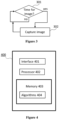
- Figure 3 illustrates an example of capturing images periodically for the drive condition monitoring. It is determined in block 301 if it is time to capture an image of the drive for the contamination assessment. If it is time to capture the image (block 301: yes), the image is captured in block 302 by the digital camera. If it is not yet time to capture the image (block 302: no), the process continues by waiting for the pre-determined time interval to pass. After capturing the image, the image may be stored in the memory of the digital camera or transmitted to the cloud, to the edge device, or to the drive. Further, the drive may store the image in the memory of the drive or transmit the image to the cloud. The image may be stored together with a unique identifier, for example, an identifier of the drive such as a serial number.
- a unique identifier for example, an identifier of the drive such as a serial number.
- the identifier of the image may be the identifier stored with the at least one reference image, to enable matching the image to the corresponding at least one reference image and the corresponding drive.
- the identifier of the image may be mapped with the identifier of the at least one reference image, for example, using a mapping table.
- the at least one reference image may be stored in the digital camera or in the drive, and the assessment tool obtains the image together with the at least one reference image.
- Utilizing the method for drive condition monitoring enables avoiding periodical maintenance visits of a service engineer to drives that are not in need of a cleaning. It also enables preventing a drive failure caused by not cleaning the drive in time, which may cause costly factory downtimes.
- Figure 4 is a simplified block diagram illustrating some units for an apparatus (device, equipment) 400 configured to perform at least some functionalities/operations described above, for example by means of Figures 1 to 3 and any combination thereof.
- the apparatus 400 comprises one or more interface (IF) entities 401, such as one or more user interfaces, and one or more processing entities 402 connected to various interface entities 401 and to one or more memories 403.
- IF interface
- processing entities 402 connected to various interface entities 401 and to one or more memories 403.
- the one or more interface entities 401 are entities for receiving and transmitting information, such as communication interfaces comprising hardware and/or software for realizing communication connectivity according to one or more communication protocols, or for realizing data storing and fetching.
- a processing entity 402 is capable of performing calculations and configured to implement at least part of functionalities/operations described above, for example by means of any of Figures 1 to 3 and any combination thereof, with corresponding algorithms 404 stored in the memory 403.
- the processing entity 402 may include one or more processors, controllers, control units, micro-controllers, etc. configurable to carry out embodiments/examples/implementations or operations described above, for example by means of any of Figures 1 to 3 and any combination thereof.
- a processor is a central processing unit, but the processing entity 402 may be an additional operation processor or a multicore processor or a microprocessor.
- a memory 403 is usable for storing a computer program code required for one or more functionalities/operations described above, for example by means of any of Figures 1 to 3 and any combination thereof, that is, the algorithms 404 for implementing the functionalities/operations described above by means of any of Figures 1 to 3 and any combination thereof.
- the memory 403 may also be usable for storing, at least temporarily, other possible information required for one or more functionalities/operations described above, for example by means of any of Figures 1 to 3 and any combination thereof.
- the memory may comprise a data buffer that may, at least temporarily, store content for a message before it is sent, or store requested information and content for displaying a message thread or a message.
- the methods described herein may be configured as a computer or a processor, or a microprocessor, such as a single-chip computer element, or as a chipset, or one or more logic gates including at least a memory for providing storage area used for arithmetic operations and an operation processor for executing the arithmetic operations.
- Each or some or one of the algorithms for functions/operations described above may be comprised in one or more computer processors, application-specific integrated circuits (ASIC), digital signal processors (DSP), digital signal processing devices (DSPD), programmable logic devices (PLD), field-programmable gate arrays (FPGA), graphics processing units (GPU), and/or other hardware components that have been programmed and/or will be programmed by downloading computer program code (one or more algorithms) in such a way as to carry out one or more functions of one or more embodiments/examples.
- ASIC application-specific integrated circuits
- DSP digital signal processors
- DSPD digital signal processing devices
- PLD programmable logic devices
- FPGA field-programmable gate arrays
- GPU graphics processing units
- An embodiment provides a computer program embodied on any client-readable distribution/data storage medium or memory unit(s) or article(s) of manufacture, comprising program instructions executable by one or more processors/computers, which instructions, when loaded into an apparatus (device, equipment), constitute an entity providing corresponding functionality, or at least part of the corresponding functionality.
- Programs also called program products, including software routines, program snippets constituting "program libraries", applets and macros, can be stored in any medium, including non-transitory computer readable storage medium, and may be downloaded into an apparatus.
- each or some or one of the algorithms for one or more functions/operations described above may be comprised in an element that comprises one or more arithmetic logic units, a number of special registers and control circuits.
Landscapes
- Engineering & Computer Science (AREA)
- Physics & Mathematics (AREA)
- General Physics & Mathematics (AREA)
- Theoretical Computer Science (AREA)
- Chemical & Material Sciences (AREA)
- Immunology (AREA)
- Health & Medical Sciences (AREA)
- Life Sciences & Earth Sciences (AREA)
- Pathology (AREA)
- Analytical Chemistry (AREA)
- Biochemistry (AREA)
- General Health & Medical Sciences (AREA)
- Computer Vision & Pattern Recognition (AREA)
- Multimedia (AREA)
- Signal Processing (AREA)
- Software Systems (AREA)
- Quality & Reliability (AREA)
- Studio Devices (AREA)
- Investigating Materials By The Use Of Optical Means Adapted For Particular Applications (AREA)
Abstract
The present document discloses a computer-implemented method for condition monitoring of an industrial drive. According to an aspect, the method comprises: obtaining an image of a component surface of the industrial drive, wherein the image comprises a first number of pixels; determining, using the image and at least one reference image for the component surface, a contamination index of the image, wherein the at least one reference image comprises the first number of pixels; and triggering, in response to the contamination index being above a pre-determined first threshold, a maintenance warning.
Description
- The invention relates to a method for monitoring drive condition by using machine vision.
- Industrial drives are operated in environments where small particles such as dust or metals are accumulated. This may cause build-up inside a drive over time and eventually lead into a drive failure and an unplanned shutdown, potentially caused by excessive heat generation, moisture, or conductive particles.
- It is non-trivial how to determine when the condition of a drive has reached the point of maintenance demand. Thus, it would be beneficial to find a method for drive condition monitoring that would enable optimizing maintenance cycles and preventing drive failures.
- According to an aspect, there is provided the subject-matter of independent claims. Dependent claims define some embodiments.
- Some embodiments provide a computer-implemented method for condition monitoring of an industrial drive, the method comprising obtaining an image of a component surface of the industrial drive, determining, using the image and at least one reference image for the component surface, a contamination index of the image, and triggering, in response to the contamination index being above a pre-determined first threshold, a maintenance warning.
- In the following, various example embodiments will be described in greater detail with reference to the accompanying drawings, in which
-
Figure 1 shows simplified architecture of a system; -
Figures 2 and3 are flow charts illustrating example functionalities; and -
Figure 4 illustrates an exemplary embodiment of an apparatus. - The following embodiments are exemplary. Although the specification may refer to "an", "one", or "some" embodiment(s) in several locations, this does not necessarily mean that each such reference is to the same embodiment(s), or that the feature only applies to a single embodiment. Single features of different embodiments may also be combined to provide other embodiments. Furthermore, words "comprising" and "including" should be understood as not limiting the described embodiments/examples to consist of only those features that have been mentioned and such embodiments may contain also features/structures that have not been specifically mentioned. Further, although terms including ordinal numbers, such as "first", "second", etc., may be used for describing various elements, the structural elements are not restricted by the terms. The terms are used merely for the purpose of distinguishing an element from other elements. For example, a first element could be termed a second element, and similarly, a second element could be also termed a first element without departing from the scope of the present disclosure.
- The present invention is applicable to any apparatus, system, or equipment that is configured or configurable to monitor condition of one or more industrial drives. Different embodiments and examples are described below using single units, models, equipment, and memory, without restricting the embodiments/examples to such a solution. Concepts called cloud computing and/or virtualization may be used. The virtualization may allow a single physical computing device to host one or more instances of virtual machines that appear and operate as independent computing devices, so that a single physical computing device can create, maintain, delete, or otherwise manage virtual machines in a dynamic manner. It is also possible that device operations will be distributed among a plurality of servers, nodes, devices, or hosts. In cloud computing network devices, computing devices, and/or storage devices provide shared resources. Some other technology advancements, such as Software-Defined Networking (SDN), may cause one or more of the functionalities described below to be migrated to any corresponding abstraction or apparatus or device. Therefore, all words and expressions should be interpreted broadly, and they are intended to illustrate, not to restrict, the embodiment.
- A general exemplary architecture of a system performing drive condition monitoring is illustrated in
Figure 1. Figure 1 is a simplified system architecture showing only some devices, apparatuses, and functional entities, all being logical units whose implementation and/or number may differ from what is shown. The connections shown inFigure 1 are logical connections; the actual physical connections may be different. It is apparent to a person skilled in the art that the system comprises any number of shown elements, other equipment, other functions, and other structures that are not illustrated. They, as well as the protocols used, are well known by persons skilled in the art and are irrelevant to the actual invention. Therefore, they need not to be discussed in more detail here. - In the example illustrated by
Figure 1 , thesystem 100 comprises one or more drive enclosures 110 (only one illustrated inFigure 1 ) comprising a variable-frequency drive 130 located, for example, in an industrial plant. The variable-frequency drive 130 is connected over one or more networks (none shown inFigure 1 ) to one ormore clouds 140 or cloud platforms (only one illustrated inFigure 1 ) which are connected over one or more networks to one ormore user devices 150. Alternatively, the variable-frequency drive may be connected over one or more networks to an edge device that is connected over one or more networks to the one ormore clouds 140. Edge devices are pieces of equipment that may transmit data between a local network and a cloud. Thedrive enclosure 110 comprises also at least onedigital camera 120 and at least onelighting source 125. The one or more networks may be any wired or wireless network, or a combination thereof, enabling transmission of information between different apparatuses/devices over the network. These include, but are not limited to, local area networks (LAN), cellular networks, and wireless local area networks (WLAN). - The at least one
digital camera 120 is fixedly installed in the drive enclosure in relation to thedrive 130. The at least onelighting source 125 may be an internal lighting source of thecamera 120 or an external lighting source connected to thecamera 120 and fixedly installed in relation to the drive and/or camera. Thelighting source 125 may be, for example, a light-emitting diode (LED) light. The direction of light from thelighting source 125 is fixed in relation to thedrive 130. Thecamera 120 is configured to capture images of thedrive 130 by illuminating a component surface of thedrive 130 such as, e.g., a power unit board surface, with thelighting source 125 and capturing light that is reflected from the component surface of thedrive 130. Thecamera 120 may be equipped with a colour sensor, such as an RGB colour sensor. Thedigital camera 120 is configured to capture image data, for example, periodically at regular time intervals, and store the image data to acontrol tool 132 of thedrive 130 or amemory 134 of the drive. Alternatively, thecamera 120 may be configured to transmit the image data to acloud 140. - The variable-
frequency drive 130 may be used in electro-mechanical drive systems for controlling an alternating current (AC) motor speed and/or torque by varying, for example, frequency, current, and/or voltage of an electrical supply to the motor. The variable-frequency drive 130 may be called an adjustable-frequency drive, a variable-voltage drive, a variable-speed drive, an alternating current (AC) drive, a micro drive, or an inverter drive, or herein shortly a drive. Thedrive 130 comprises thecontrol tool 132 for adjusting and controlling the functions of thedrive 130. Thedrive 130 may store in thememory 134, which may be internal or external, the image data received from thedigital camera 120. - In the cloud-based deployment, the one or
more clouds 140 provide, for example, condition monitoring service for remote support using collecteddata 142 stored in thecloud 140 and performingassessment 144 in thecloud 140. In the illustrated example ofFigure 1 , the collecteddata 142 stored in thecloud 140 comprise at least the image data captured by the at least onedigital camera 120 and obtained from thedrive enclosure 110. The collecteddata 142 may comprise also other data, such as pre-determined thresholds for drive condition parameters and results from previous condition assessments. An assessment tool or anassessment unit 144 may be a condition monitoring tool configured to, for example, identify one or more drive condition parameters indicative of a developing fault in thedrive 130. The details of how data are stored in the cloud or in any other shared data storage for condition monitoring are not relevant for the implementation and therefore they are not described in more detail here. It is obvious for one skilled in the art that any known or future storage method may be used. Further, implementing the examples described herein using a non-cloud deployment for remote support is a straightforward task for one skilled in the art. - The
assessment tool 144 is also configured to trigger a maintenance warning to the one ormore user devices 150. Auser device 150 refers to a computing device (equipment, apparatus) that may be a portable device or a desktop device such as a personal computer, and it may also be referred to as a user terminal or a user apparatus. Portable computing devices (apparatuses) include wireless mobile communication devices operating with or without a subscriber identification module (SIM) in hardware or in software, including, but not limited to, the following types of devices: a mobile phone, a smartphone, a personal digital assistant (PDA), a handset, a laptop and/or touch screen computer, a tablet (tablet computer), a multimedia device, a wearable computer, and other types of wearable devices, such as clothing and accessories incorporating computer and advanced electronic technologies. Theuser device 150 may comprise one or more user interfaces. The one or more user interfaces may be any kind of a user interface, for example a screen, a keypad, a loudspeaker, a microphone, a touch user interface, an integrated display device, and/or an external display device. Theuser device 150 may be configured to perform the maintenance warning triggered by theassessment tool 144. For that purpose, theuser device 150 may be capable of installing applications. The maintenance warning may be, for example, a text message, an image message, a sound alarm, or a flashing light. - In another example, the collected
data 142 are stored in thememory 134 of thedrive 130, theassessment tool 144 is comprised in thecontrol tool 132 of thedrive 130, and the drive may be connected to theuser device 150 over the one or more networks. Alternatively, theuser device 150 may be located in the vicinity of thedrive 130 and thedrive 130 may be connected to theuser device 150 over a short-range wireless connection such as Bluetooth, over a Universal Serial Bus (USB) connection, or via near-field communication (NFC). Assessment for condition monitoring is performed in thecontrol tool 132 of thedrive 130 and thecontrol tool 132 is configured to trigger a maintenance warning directly to theuser device 150. - In the illustrated example of
Figure 2 , assessment for drive condition monitoring is performed by determining a contamination index. The contamination index can be used to estimate a need of maintenance for the drive. The monitoring is performed periodically at pre-determined time intervals, for example, hourly, daily, or weekly, to reduce unplanned or interruptive maintenance downtime. Unplanned maintenance time may occur due to, for example, a drive failure caused by contamination. On the other hand, the condition monitoring may be used to reduce unnecessary cleaning of the drive when it is still substantially uncontaminated. - Referring to
Figure 2 , an image captured by a digital camera is obtained inblock 201. The image may be received by the assessment tool from the control tool of the drive, or the image may be received directly from the digital camera. Alternatively, the image may have been stored earlier in the collected data in the cloud and may now be retrieved by the assessment tool. The image comprises a first number of pixels. The image may be a grayscale image, or it may comprise a second number of colour channels, such as RGB channels or CMYK channels. A contamination index of the image is determined inblock 202 using at least one reference image. The at least one reference image is an image captured by the installed digital camera from the component surface of the drive while it is clean, for example, immediately after the drive is installed or immediately after a maintenance cleaning is performed. An angle of light and an angle of view used for capturing are same for both the at least one reference image and the image. The at least one reference image may be stored together with a unique identifier, for example, an identifier of the drive such as a serial number, to enable matching the at least one reference image to the corresponding drive. The contamination index may be determined by calculating, per a pixel of the first number of pixels, an absolute value of a deviation of an intensity value of the image from an intensity value of the at least one reference image, and adding together, for the first number of pixels, the absolute values calculated. This calculation of the contamination index may be expressed as an equation

- If the at least one reference image comprises two or more reference images, then an average such as, e.g., a mean or a median of the intensity values of the two or more reference images may be used in the determination of the contamination index. This calculation of the contamination index may be expressed as an equation

- It is determined in
block 203 whether the determined contamination index is above a pre-determined threshold. The pre-determined threshold may be determined based on a knowledge of a level of contamination causing drive failure. The level of contamination causing drive failure may be determined, for example, by observing drive contamination of a plurality of drives without performing cleaning maintenance until drive failure occurs. Additionally, or alternatively, a machine-learning model may be trained for determining a suitable threshold. The pre-determined threshold may also be re-determined or adjusted, for example, based on observations made by maintenance personnel. For example, a maintenance warning may have been triggered even though the drive is not contaminated enough to need a cleaning, or an unplanned maintenance downtime may have occurred due to a drive failure even though the maintenance warning was not triggered. - If the contamination index is above the pre-determined threshold (block 203: yes), the maintenance warning is triggered in
block 204. The process may continue by, for example, obtaining images periodically and triggering the maintenance warning until the drive is cleaned. Alternatively, obtaining images may be interrupted and then continued, for example, when the maintenance warning is acknowledged as received. - If the contamination index is below the pre-determined threshold (block 203: no), the process continues by obtaining in
block 201 another image, for example, after a pre-determined time interval has passed. The determined contamination index may be stored in the memory of the assessment unit, for example, for tracking the development of the contamination index of the drive over time. - In an embodiment a single reference image may be used for a plurality of similar drives, for example two or three drives.
-
Figure 3 illustrates an example of capturing images periodically for the drive condition monitoring. It is determined inblock 301 if it is time to capture an image of the drive for the contamination assessment. If it is time to capture the image (block 301: yes), the image is captured inblock 302 by the digital camera. If it is not yet time to capture the image (block 302: no), the process continues by waiting for the pre-determined time interval to pass. After capturing the image, the image may be stored in the memory of the digital camera or transmitted to the cloud, to the edge device, or to the drive. Further, the drive may store the image in the memory of the drive or transmit the image to the cloud. The image may be stored together with a unique identifier, for example, an identifier of the drive such as a serial number. The identifier of the image may be the identifier stored with the at least one reference image, to enable matching the image to the corresponding at least one reference image and the corresponding drive. Alternatively, the identifier of the image may be mapped with the identifier of the at least one reference image, for example, using a mapping table. - In an embodiment, the at least one reference image may be stored in the digital camera or in the drive, and the assessment tool obtains the image together with the at least one reference image.
- The blocks and related functions described above in
Figures 2 and3 are in no absolute chronological order, and some of the blocks may be performed simultaneously or in an order differing from the given one. Other functions can also be executed between the blocks or within the blocks. Some of the blocks or part of the blocks can also be left out or replaced by a corresponding block or part of a block. - Utilizing the method for drive condition monitoring enables avoiding periodical maintenance visits of a service engineer to drives that are not in need of a cleaning. It also enables preventing a drive failure caused by not cleaning the drive in time, which may cause costly factory downtimes.
-
Figure 4 is a simplified block diagram illustrating some units for an apparatus (device, equipment) 400 configured to perform at least some functionalities/operations described above, for example by means ofFigures 1 to 3 and any combination thereof. In the illustrated example, theapparatus 400 comprises one or more interface (IF)entities 401, such as one or more user interfaces, and one ormore processing entities 402 connected tovarious interface entities 401 and to one ormore memories 403. - The one or
more interface entities 401 are entities for receiving and transmitting information, such as communication interfaces comprising hardware and/or software for realizing communication connectivity according to one or more communication protocols, or for realizing data storing and fetching. - A
processing entity 402 is capable of performing calculations and configured to implement at least part of functionalities/operations described above, for example by means of any ofFigures 1 to 3 and any combination thereof, withcorresponding algorithms 404 stored in thememory 403. Theprocessing entity 402 may include one or more processors, controllers, control units, micro-controllers, etc. configurable to carry out embodiments/examples/implementations or operations described above, for example by means of any ofFigures 1 to 3 and any combination thereof. Generally, a processor is a central processing unit, but theprocessing entity 402 may be an additional operation processor or a multicore processor or a microprocessor. - A
memory 403 is usable for storing a computer program code required for one or more functionalities/operations described above, for example by means of any ofFigures 1 to 3 and any combination thereof, that is, thealgorithms 404 for implementing the functionalities/operations described above by means of any ofFigures 1 to 3 and any combination thereof. Thememory 403 may also be usable for storing, at least temporarily, other possible information required for one or more functionalities/operations described above, for example by means of any ofFigures 1 to 3 and any combination thereof. The memory may comprise a data buffer that may, at least temporarily, store content for a message before it is sent, or store requested information and content for displaying a message thread or a message. - As a summary, the methods described herein, for example by means of any of
Figures 1 to 3 and any combination thereof, may be configured as a computer or a processor, or a microprocessor, such as a single-chip computer element, or as a chipset, or one or more logic gates including at least a memory for providing storage area used for arithmetic operations and an operation processor for executing the arithmetic operations. Each or some or one of the algorithms for functions/operations described above, for example by means of any ofFigures 1 to 3 and any combination thereof, may be comprised in one or more computer processors, application-specific integrated circuits (ASIC), digital signal processors (DSP), digital signal processing devices (DSPD), programmable logic devices (PLD), field-programmable gate arrays (FPGA), graphics processing units (GPU), and/or other hardware components that have been programmed and/or will be programmed by downloading computer program code (one or more algorithms) in such a way as to carry out one or more functions of one or more embodiments/examples. - An embodiment provides a computer program embodied on any client-readable distribution/data storage medium or memory unit(s) or article(s) of manufacture, comprising program instructions executable by one or more processors/computers, which instructions, when loaded into an apparatus (device, equipment), constitute an entity providing corresponding functionality, or at least part of the corresponding functionality. Programs, also called program products, including software routines, program snippets constituting "program libraries", applets and macros, can be stored in any medium, including non-transitory computer readable storage medium, and may be downloaded into an apparatus. In other words, each or some or one of the algorithms for one or more functions/operations described above, for example by means of any of
Figures 1 to 3 and any combination thereof, may be comprised in an element that comprises one or more arithmetic logic units, a number of special registers and control circuits. - It will be obvious to a person skilled in the art that, as the technology advances, the inventive concept can be implemented in various ways. The invention and its embodiments are not limited to the examples described above but may vary within the scope of the claims.
Claims (12)
- A computer-implemented method for condition monitoring of an industrial drive, the method comprising:obtaining an image of a component surface of the industrial drive, wherein the image comprises a first number of pixels;determining, using the image and at least one reference image for the component surface, a contamination index of the image, wherein the at least one reference image comprises the first number of pixels; andtriggering, in response to the contamination index being above a pre-determined first threshold, a maintenance warning.
- A computer-implemented method according to claim 1, wherein the obtaining the image comprises receiving the image or retrieving the image from a memory.
- A computer-implemented method according to claim 1 or 2, further comprising:illuminating, by a light source, the component surface at least while capturing the image;capturing, by a digital camera, light reflected from the component surface; andstoring or transmitting the image.
- A computer-implemented method according to any of the preceding claims, wherein the at least one reference image is captured before the component surface is exposed to contamination.
- A computer-implemented method according to any of the preceding claims, wherein the determining the contamination index of the image comprises:calculating, per a pixel of the first number of pixels, an absolute value of a deviation of an intensity value of the image from an intensity value of the at least one reference image; anddetermining the contamination index by adding together, for the first number of pixels, the absolute values calculated.
- A computer-implemented method according to any of claims 1 to 4, wherein the image and the at least one reference image comprise a second number of colour channels, and the determining the contamination index of the image comprises:calculating, per a colour channel of the second number of colour channels and per a pixel of the first number of pixels, an absolute value of a deviation of an intensity value of the image from an intensity value of the at least one reference image; anddetermining the contamination index by adding together, for the first number of pixels and for the second number of colour channels, the absolute values calculated.
- A condition monitoring system comprising at least:a digital camera fixedly installed in relation to an industrial drive and configured to capture an image of a component surface of the industrial drive comprising a first number of pixels;means for determining, using the image and at least one reference image for the component surface, a contamination index of the image, wherein the at least one reference image comprises the first number of pixels; andmeans for triggering, in response to the contamination index being above a pre-determined first threshold, a maintenance warning.
- A condition monitoring system according to claim 7, further comprising:
a light source fixedly installed in relation to the industrial drive and configured to illuminate the component surface at least while the digital camera is capturing the image. - A condition monitoring system according to claim 8, wherein the digital camera is configured to capture light reflected from the component surface.
- A condition monitoring system according to any of claims 7 to 9, wherein the digital camera is further configured to capture the at least one reference image before the component surface is exposed to contamination.
- A condition monitoring system according to any of claims 7 to 10, wherein the means for determining the contamination index are further configured to perform:calculating, per a pixel of the first number of pixels, an absolute value of a deviation of an intensity value of the image from an intensity value of the at least one reference image; anddetermining the contamination index by adding together, for the first number of pixels, the absolute values calculated.
- A condition monitoring system according to any of claims 7 to 10, wherein the image and the at least one reference image comprise a second number of colour channels, and the means for determining the contamination index are further configured to perform:calculating, per a colour channel of the second number of colour channels and per a pixel of the first number of pixels, an absolute value of a deviation of an intensity value of the image from an intensity value of the at least one reference image; anddetermining the contamination index by adding together, for the first number of pixels and for the second number of colour channels, the absolute values calculated.
Priority Applications (3)
| Application Number | Priority Date | Filing Date | Title |
|---|---|---|---|
| EP23157482.3A EP4418204A1 (en) | 2023-02-20 | 2023-02-20 | Method for drive condition monitoring |
| US18/426,428 US20240280503A1 (en) | 2023-02-20 | 2024-01-30 | Drive condition monitoring |
| CN202410181395.3A CN118518681A (en) | 2023-02-20 | 2024-02-18 | Method for driver condition monitoring |
Applications Claiming Priority (1)
| Application Number | Priority Date | Filing Date | Title |
|---|---|---|---|
| EP23157482.3A EP4418204A1 (en) | 2023-02-20 | 2023-02-20 | Method for drive condition monitoring |
Publications (1)
| Publication Number | Publication Date |
|---|---|
| EP4418204A1 true EP4418204A1 (en) | 2024-08-21 |
Family
ID=85285277
Family Applications (1)
| Application Number | Title | Priority Date | Filing Date |
|---|---|---|---|
| EP23157482.3A Pending EP4418204A1 (en) | 2023-02-20 | 2023-02-20 | Method for drive condition monitoring |
Country Status (3)
| Country | Link |
|---|---|
| US (1) | US20240280503A1 (en) |
| EP (1) | EP4418204A1 (en) |
| CN (1) | CN118518681A (en) |
Citations (1)
| Publication number | Priority date | Publication date | Assignee | Title |
|---|---|---|---|---|
| US6661912B1 (en) * | 1998-08-03 | 2003-12-09 | Hitachi Electronics Engineering Co., Ltd. | Inspecting method and apparatus for repeated micro-miniature patterns |
Family Cites Families (9)
| Publication number | Priority date | Publication date | Assignee | Title |
|---|---|---|---|---|
| US9082201B2 (en) * | 2013-01-04 | 2015-07-14 | International Business Machines Corporation | Surface contamination determination system |
| FR3047832B1 (en) * | 2016-02-12 | 2019-09-27 | Idemia Identity And Security | METHOD FOR DETERMINING A COLOR VALUE OF AN OBJECT IN AN IMAGE |
| GB2553830B (en) * | 2016-09-16 | 2020-02-12 | Scient Instruments Limited | A dust detector and method |
| CN108760755A (en) * | 2018-07-03 | 2018-11-06 | 银河水滴科技(北京)有限公司 | A kind of dust granule detection method and device |
| CN109459354A (en) * | 2019-01-20 | 2019-03-12 | 华东交通大学 | A kind of workshop dust fall amount automatic detection device and method based on machine vision |
| CA3259321A1 (en) * | 2021-07-06 | 2023-01-12 | Industrial Intelligence, Inc. | Continuous dust accumulation monitoring system, device and method with impaired optics detection and cleaning |
| CN113284148B (en) * | 2021-07-23 | 2021-10-15 | 苏州高视半导体技术有限公司 | Screen dust filtering method |
| CN114049490B (en) * | 2021-11-05 | 2024-06-25 | 河南鑫安利安全科技股份有限公司 | Intelligent occupational health early warning method and system |
| CN119811023A (en) * | 2024-12-03 | 2025-04-11 | 内蒙古和林发电有限责任公司 | A 660MW thermal power unit maintenance warning device |
-
2023
- 2023-02-20 EP EP23157482.3A patent/EP4418204A1/en active Pending
-
2024
- 2024-01-30 US US18/426,428 patent/US20240280503A1/en active Pending
- 2024-02-18 CN CN202410181395.3A patent/CN118518681A/en active Pending
Patent Citations (1)
| Publication number | Priority date | Publication date | Assignee | Title |
|---|---|---|---|---|
| US6661912B1 (en) * | 1998-08-03 | 2003-12-09 | Hitachi Electronics Engineering Co., Ltd. | Inspecting method and apparatus for repeated micro-miniature patterns |
Non-Patent Citations (1)
| Title |
|---|
| PIPPOLA JUHA ET AL: "Development of dust test method for motor drives", 2017 IMAPS NORDIC CONFERENCE ON MICROELECTRONICS PACKAGING (NORDPAC), IEEE, 18 June 2017 (2017-06-18), pages 43 - 46, XP033130240, DOI: 10.1109/NORDPAC.2017.7993161 * |
Also Published As
| Publication number | Publication date |
|---|---|
| CN118518681A (en) | 2024-08-20 |
| US20240280503A1 (en) | 2024-08-22 |
Similar Documents
| Publication | Publication Date | Title |
|---|---|---|
| KR102494946B1 (en) | Battery detection method and device (BATTERY DETECTION METHOD AND DEVICE) | |
| CN108124132A (en) | A kind of method for safety monitoring and device | |
| US12337359B2 (en) | Method and apparatus for detecting wafer cleaning anomalies | |
| WO2019132564A1 (en) | Method and system for classifying time-series data | |
| MX2008011796A (en) | A date remote monitoring system of essential security and a monitoring method thereof. | |
| CN103873637A (en) | Cross-device transmission method and device | |
| CN105234951A (en) | Intelligent guiding type mechanical arm vision system and work method thereof | |
| CN104144212B (en) | A kind of virtual desktop image transfer method, apparatus and system | |
| CN111601013A (en) | Method and apparatus for processing video frames | |
| EP4418204A1 (en) | Method for drive condition monitoring | |
| CN115333928A (en) | Network early warning method and device, electronic equipment and storage medium | |
| CN112025703A (en) | Robot self-diagnosis method, device and system | |
| KR101307583B1 (en) | Remote-control and device efficiency-management system according to imaging process a semiconductor device and drive method of the same | |
| CN103905782B (en) | Mobile commanding system and mobile command terminal system | |
| JP2016173622A (en) | Information processing system | |
| CN110751055B (en) | Intelligent manufacturing system | |
| CN211402188U (en) | Cloud cloth inspection system | |
| US20160330253A1 (en) | Communication device, communication system, communication method, and storage medium | |
| CN113358020A (en) | Machine vision detection system and method | |
| JP7153766B2 (en) | How to detect PLC asset switching | |
| JP7272441B2 (en) | Cable removal prevention system, management device, cable removal prevention method, and program | |
| CN106034036B (en) | Server state detecting real-time method and system, terminal installation | |
| CN107084707A (en) | A kind of paper production exception monitoring apparatus and method | |
| CN114783082A (en) | A kind of inspection method, device, equipment and storage medium | |
| CN207625707U (en) | Intelligent security control system based on GIS |
Legal Events
| Date | Code | Title | Description |
|---|---|---|---|
| PUAI | Public reference made under article 153(3) epc to a published international application that has entered the european phase |
Free format text: ORIGINAL CODE: 0009012 |
|
| STAA | Information on the status of an ep patent application or granted ep patent |
Free format text: STATUS: THE APPLICATION HAS BEEN PUBLISHED |
|
| AK | Designated contracting states |
Kind code of ref document: A1 Designated state(s): AL AT BE BG CH CY CZ DE DK EE ES FI FR GB GR HR HU IE IS IT LI LT LU LV MC ME MK MT NL NO PL PT RO RS SE SI SK SM TR |
|
| STAA | Information on the status of an ep patent application or granted ep patent |
Free format text: STATUS: REQUEST FOR EXAMINATION WAS MADE |
|
| 17P | Request for examination filed |
Effective date: 20250124 |