EP4418203A1 - Region detection program, device, and method - Google Patents
Region detection program, device, and method Download PDFInfo
- Publication number
- EP4418203A1 EP4418203A1 EP21960618.3A EP21960618A EP4418203A1 EP 4418203 A1 EP4418203 A1 EP 4418203A1 EP 21960618 A EP21960618 A EP 21960618A EP 4418203 A1 EP4418203 A1 EP 4418203A1
- Authority
- EP
- European Patent Office
- Prior art keywords
- person
- region
- image
- images
- height
- Prior art date
- Legal status (The legal status is an assumption and is not a legal conclusion. Google has not performed a legal analysis and makes no representation as to the accuracy of the status listed.)
- Pending
Links
Images






Classifications
-
- G—PHYSICS
- G06—COMPUTING OR CALCULATING; COUNTING
- G06V—IMAGE OR VIDEO RECOGNITION OR UNDERSTANDING
- G06V10/00—Arrangements for image or video recognition or understanding
- G06V10/20—Image preprocessing
- G06V10/25—Determination of region of interest [ROI] or a volume of interest [VOI]
-
- G—PHYSICS
- G06—COMPUTING OR CALCULATING; COUNTING
- G06T—IMAGE DATA PROCESSING OR GENERATION, IN GENERAL
- G06T7/00—Image analysis
-
- G—PHYSICS
- G06—COMPUTING OR CALCULATING; COUNTING
- G06T—IMAGE DATA PROCESSING OR GENERATION, IN GENERAL
- G06T7/00—Image analysis
- G06T7/50—Depth or shape recovery
- G06T7/55—Depth or shape recovery from multiple images
- G06T7/593—Depth or shape recovery from multiple images from stereo images
-
- G—PHYSICS
- G06—COMPUTING OR CALCULATING; COUNTING
- G06T—IMAGE DATA PROCESSING OR GENERATION, IN GENERAL
- G06T7/00—Image analysis
- G06T7/60—Analysis of geometric attributes
-
- G—PHYSICS
- G06—COMPUTING OR CALCULATING; COUNTING
- G06T—IMAGE DATA PROCESSING OR GENERATION, IN GENERAL
- G06T7/00—Image analysis
- G06T7/70—Determining position or orientation of objects or cameras
-
- G—PHYSICS
- G06—COMPUTING OR CALCULATING; COUNTING
- G06V—IMAGE OR VIDEO RECOGNITION OR UNDERSTANDING
- G06V20/00—Scenes; Scene-specific elements
- G06V20/50—Context or environment of the image
- G06V20/52—Surveillance or monitoring of activities, e.g. for recognising suspicious objects
-
- G—PHYSICS
- G06—COMPUTING OR CALCULATING; COUNTING
- G06V—IMAGE OR VIDEO RECOGNITION OR UNDERSTANDING
- G06V40/00—Recognition of biometric, human-related or animal-related patterns in image or video data
- G06V40/10—Human or animal bodies, e.g. vehicle occupants or pedestrians; Body parts, e.g. hands
- G06V40/103—Static body considered as a whole, e.g. static pedestrian or occupant recognition
-
- G—PHYSICS
- G06—COMPUTING OR CALCULATING; COUNTING
- G06V—IMAGE OR VIDEO RECOGNITION OR UNDERSTANDING
- G06V2201/00—Indexing scheme relating to image or video recognition or understanding
- G06V2201/07—Target detection
Definitions
- the present technique relates to a region detection program, a region detection apparatus, and a region detection method.
- a 3D model generation apparatus that generates a 3D model of a subject from video captured by a plurality of cameras.
- This apparatus acquires a silhouette image for each viewpoint from a multi-viewpoint video, and generates a low-resolution voxel model having a voxel size of a first size from a plurality of silhouette images by a view volume intersection method. Further, this apparatus classifies the low-resolution voxel model based on a feature thereof, and determines a second size smaller than the first size for each low-resolution voxel model based on a classification result.
- this apparatus generates a high-resolution voxel model having a voxel size of the second size for each 3D bounding box of the low-resolution voxel model, and outputs a 3DCG model of the subject based on the high-resolution voxel model.
- Patent Document 1 Japanese Laid-Open Patent Publication No. 2021-071749
- Non-Patent Document 1 Hideo Saito, Makoto Kimura, Satoshi Yaguchi, Naho Inamoto, "View Interpolation of Multiple Cameras Based on Projective Geometry", 2002 .
- the bounding box When detecting the bounding box as a region indicating a target person from an image by using a machine learning model, a case occurs sometimes in which the bounding box may not be detected or may be erroneously detected. If such non-detection or erroneous detection of the bounding box occurs in any image of the multi-viewpoint image for acquiring the three dimensional information of the person, the three dimensional information may not be accurately acquired in the subsequent processes.
- the disclosed technique aims to appropriately interpolate the bounding box which is not detected or is erroneously detected in the multi-viewpoint image.
- the disclosed technique acquires images captured by a plurality of imaging apparatuses that capture a person from different directions.
- the disclosed technique inputs the acquired images to a machine learning model generated in advance by machine learning so as to detect a region of the person included in the images, and detects a region indicating the person from each of the acquired images.
- the disclosed technique interpolates a region indicating the person in a second image of the acquired images based on a region of the person detected from a first image of the acquired images and a parameter of each of the plurality of imaging apparatuses.
- the region detection apparatus 10 is coupled to each of a plurality of cameras 30n that capture images of a gymnast 90 at viewpoints n from respective different directions.
- n 1, 2, 3, and a camera 301 that captures an image from a viewpoint 1, a camera 302 that captures an image from a viewpoint 2, and a camera 303 that captures an image from a viewpoint 3 are coupled to the region detection apparatus 10.
- a number of cameras 30n coupled to the region detection apparatus 10 is not limited to the example of FIG. 1 .
- the cameras 30n are installed at different positions in substantially the same horizontal plane at an angle at which the gymnast 90 is within an imaging range.
- the cameras 30n are arranged horizontally side by side so as to surround the gymnast 90.
- substantially in the same horizontal plane means a case where a height of the camera 30n from a floor surface may be regarded as substantially the same, and a case where a difference in the height of the camera 30n from the floor surface is equal to or less than a predetermined value.
- a video captured by the camera 30n is sequentially input to the region detection apparatus 10. Note that time information is associated with each frame included in the video captured by each camera 30n, and the video captured by each camera 30n may be synchronized based on this time information.
- the region detection apparatus 10 functionally includes an acquisition unit 12, a detection unit 14, and an interpolation unit 16. Further, a detection model 20 is stored in a predetermined storage area of the region detection apparatus 10.
- the acquiring unit 12 acquires, as a multi-viewpoint image, a set of images indicated by the frame corresponding to the time information in the video input from the camera 30n to the region detection apparatus 10.
- an image captured by the camera 30n is referred to as an image 40n.
- the detecting unit 14 inputs the image 40n included in the multi-viewpoint image obtained by the obtaining unit 12 to the detection model 20, and detects a two dimensional boundary box (hereinafter, also referred to as "2D-BB") as a region indicating a person from each image 40n.
- the detection model 20 is generated in advance by using, as training data, images in which the correct the 2D-BB is given to images in which gymnasts in various postures are captured.
- the detection model 20 is an example of a "machine learning model" of the disclosed technology. For example, as illustrated in FIG. 3 , the detection unit 14 detects a circumscribed rectangle of a region indicating the gymnast 90 in the image 40n as 2D-BB42n.
- the interpolation unit 16 interpolates the 2D-BB42n in a second image of the multi-viewpoint image based on a parameter of each camera 30n and the 2D-BB42n detected from a first image of the multi-viewpoint image.
- 2D-BB42k is detected from the image 30k captured by the camera 40k of the viewpoint k
- 2D-BB42_miss is not detected from the image 40_miss captured by the camera 30_miss of the viewpoint_miss.
- the image 40k is an example of the first image
- the image 40_miss is an example of the second image.
- the 2D-BB42n may not be detected or may be erroneously detected from the image 40n. This may occur when a part of the gymnast 90 in the image 40n is blocked by an obstacle, when the posture of the gymnast 90 who is a target is not similar to any of gymnasts in the image used for training the detection model 20, or the like. It is considered that three dimensional information of the gymnast 90 is acquired based on an image in the 2D-BB42n detected from each image 40n included in the multi-viewpoint image and a recognition model for recognizing the three dimensional information such as skeleton information generated in advance by machine learning.
- heights (vertical lengths) of the 2D-BB42n in each image 40n are the same regardless of the viewpoints of each camera 30n.
- the heights of the 2D-BB42n and the heights of the 3D-BB44 are represented by lines coupling stars.
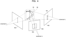
- widths (horizontal lengths) of the 2D-BB42n in each image 40n are different depending on the viewpoints of each camera 30n. In the example of FIG. 4 , the width of the 2D-BB421 detected from an image 401 and the width of the 2D-BB422 detected from an image 402 are different due to the difference in the viewpoints.
- the 2D-BB423 is not detected in an image 403, even if the perspective projection as in the related art is simply applied to interpolate from the detected the 2D-BB421 and the 2D-BB422, the widths of the 2D-BB423 may not be appropriately determined. Therefore, the 2D-BB423 in the image 403 cannot be interpolated.
- the interpolation unit 16 specifies the height of the 2D-BB42_miss in the image 40_miss in which the 2D-BB is not detected based on the height of 2D-BB42k in the image 40k in which the 2D-BB is detected and each parameter of the camera 30k. Then, the interpolation unit 16 estimates the width of the 2D-BB42_miss in the image 40_miss in which the 2D-BB is not detected, based on statistical information on the posture of the gymnast 90 and the parameter of the camera 30_miss.
- x k and y k are coordinates in the image 40k of a point at the upper left corner of 2D-BB42k, and w and h are the width and height of 2D-BB42k, respectively.
- the interpolation unit 16 specifies a coordinate [x k +w k /2, y k ] of an upper end point of a vertical center line of 2D-BB42k and a coordinate [x k +w k /2, y k +h k ] of a lower end point. Then, the interpolation unit 16 converts the coordinates of the upper end point and the lower end point into three dimensional coordinates by using the parameter of the camera 30k for converting the three dimensional coordinates into coordinates on an image plane captured by the camera 30k.
- the interpolator 16 may convert the coordinates using cv::sfm::trianglePoints defined in OpenCV (https://docs.opencv.org/3.4/d0/dbd/group triangulation.html).
- the interpolation unit 16 calculates the three dimensional coordinates of points P3d top and P3d bot in the three dimensional space corresponding to the upper end point and the lower end point, respectively, as illustrated in the following Equations (1) and (2) using a parameter matrix ProjMat cam_k of the camera 30k.
- a line coupling P3d top and the P3d bot in the three dimensional space is referred to as a person center line.
- the interpolation unit 16 converts the three dimensional coordinates of the P3d top and P3d bot into coordinates on the image 40_miss based on the parameter of the camera 30_miss, as illustrated in FIG. 6 .
- the interpolation unit 16 calculates the coordinates of an upper end point and a lower end point of a vertical center line between the 2D-BB42_miss.
- the interpolation unit 16 performs a coordinate conversion as illustrated in the following Equations (3) and (4) using a parameter matrix ProjMat cam_miss of the camera 30_miss and a parameter s representing a scale ratio between the three dimensional coordinates and a size of the image 40.
- the interpolation unit 16 calculates y miss , h miss , and x miss +w miss /2 for specifying the coordinates of the upper end point and the lower end point of the vertical center line of 2D-BB42_miss based on the above-described coordinate conversion as illustrated in the following Equations (5) to (7).
- y miss s ⁇ y miss / s
- the interpolation unit 16 specifies a line coupling the specified upper end point and the specified lower end point as the vertical center line of the 2D-BB42_miss, and specifies a length of the vertical center line as the height of the 2D-BB42_miss.
- the interpolation unit 16 estimates the width of the 2D-BB42_miss based on the specified height of the 2D-BB42_miss and the statistical information related to the posture of the gymnast 90.
- the statistical information may be, for example, a mean of a sum of the height and the width of the 3D-BB44 surrounding the gymnast in each of the cases where the gymnast takes a plurality of different postures.
- the height of the 3D-BB44 is represented by Height_3D
- the larger one of the widths is represented by Width_max_3D
- the smaller one is represented by Width_min_3D.
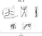
- a three dimensional model of a full-size gymnast are prepared for a plurality of postures (poses), which are acquired from a motion capture, a manual annotation, published data, and the like.
- postures postures
- three dimensional models for M poses are prepared.
- the 3D-BB44 is specified for each three dimensional model, each of the Height_3D, the Width_max_3D, and the Width_min_3D is calculated, and a mean Mean_3D illustrated in the following Equation (8) is calculated as the statistical information.
- Mean_3D 1 / M ⁇ M Width_max_3D + Width_min_3D / 2 + Height_3D
- the interpolation unit 16 calculates Width_3D of the 3D-BB44 of the gymnast 90 who is the target as illustrated in the following Equation (9) using the above-described statistical information Mean_3D and the Z top and Z bot which have been already calculated.
- Width_3D Mean_3D ⁇ ⁇ Z top ⁇ Z bot ⁇
- the interpolation unit 16 calculates the width w miss of the 2D-BB42_miss as illustrated in the following Equation (10) using the calculated Width_3D and the already-calculated Z top , Z bot , and h miss . Further, the interpolation unit 16 calculates the x miss by the calculated w miss and Equation (7) as illustrated in Equation (11) below.
- the interpolation unit 16 interpolates the 2D-BB42_miss specified by [x miss , y miss , w miss , h miss ] calculated by Equations (5), (6), (10), and (11) in the image 40_miss. Then, the interpolation unit 16 outputs the interpolated 2D-BB42_miss and 2D-BB42k together as a multi-viewpoint image in which the 2D-BB has been detected.
- the region detection apparatus 10 may be implemented by, for example, a computer 50 illustrated in FIG. 9 .
- the computer 50 includes a central processing unit (CPU) 51, a memory 52 as a temporary storage area, and a nonvolatile storage unit 53.
- the computer 50 further includes an input/output interface (I/F) 54 to which external devices such as a camera 30n, an input device, and a display are coupled, and a read/write (R/W) unit 55 that controls reading and writing of data from and to a storage media 59.
- the computer 50 includes a communication I/F 56 coupled to a network such as a Internet.
- the CPU 51, the memory 52, the storage unit 53, the input/output I/F 54, the R/W unit 55, and the communication I/F 56 are coupled to each other via a bus 57.
- the storage unit 53 may be realized by a hard disk drive (HDD), a solid state drive (SSD), a flash memory, or the like.
- the storage unit 53 as a storage medium stores an area detection program 60 for causing the computer 50 to function as the area detection apparatus 10.
- the region detection program 60 includes an acquisition process 62, a detection process 64, and an interpolation process 66. Further, he storage unit 53 includes an information storage area 70 in which information constituting the detection model 20 is stored.
- the CPU 51 reads the region detection program 60 from the storage unit 53, develops the region detection program 60 in the memory 52, and sequentially executes processes included in the region detection program 60.
- the CPU 51 operates as the acquisition unit 12 illustrated in FIG. 2 by executing the acquisition process 62. Further, the CPU 51 operates as the detection unit 14 illustrated in FIG. 2 by executing the detection process 64. Further, the CPU 51 operates as the interpolation unit 16 illustrated in FIG. 2 by executing the interpolation process 66. Further, the CPU 51 reads information from the information storage area 70 and develops the detection model 20 in the memory 52.
- the computer 50 that executes the region detection program 60 functions as the region detection apparatus 10. Note that the CPU 51 that executes the program is hardware.
- regions detection program 60 may be implemented by, for example, a semiconductor integrated circuit, for example, a graphics processing unit (GPU), an application specific integrated circuit (ASIC), or the like.
- a semiconductor integrated circuit for example, a graphics processing unit (GPU), an application specific integrated circuit (ASIC), or the like.
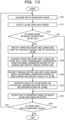
- the region detection apparatus 10 When a multi-viewpoint image is input from the camera 30n to the region detection apparatus 10, the region detection apparatus 10 performs a region detection process illustrated in FIG. 10 .
- the region detection process is an example of a region detection method of the disclosed technique.
- step S10 the acquisition unit 12 acquires a multi-viewpoint image input to the region detection apparatus 10.
- step S12 the detection unit 14 inputs each image 40n included in the acquired multi-viewpoint image to the detection model 20, and detects the 2D-BB42n from each image 40n.
- step S14 the detection unit 14 determines whether or not there is an image 40n in which the 2D-BB42n is not detected among the images 40n included in the multi-viewpoint image. If there is an image 40n in which the 2D-BB42n are not detected, the process proceeds to step S16, and if there is no image 40n in which the 2D-BB42n is not detected, the process proceeds to step S24.
- step S16 the interpolation unit 16 specifies the coordinate [x k +w k /2, y k ] of the upper end point of the vertical center line of the detected 2D-BB42k and the coordinate [x k +w k /2, y k +h k ] of the lower end point of the vertical center line.
- step S18 the interpolation unit 16 specifies the points P3d top and P3d bot obtained by converting the coordinates of the upper end point and the lower end point into the three dimensional coordinates using the parameter matrix of the camera 30k (denoted as "OK camera" in FIG. 10 ). Then, the interpolation unit 16 specifies the line coupling the P3d top and the P3d bot as the person center line.
- step S20 the interpolation unit 16 projects the three dimensional coordinates of the P3d top and P3d bot onto the image 40_miss (denoted as "miss image” in FIG. 10 ) based on the parameter matrix of the camera 30_miss (denoted as "miss camera” in FIG. 10 ).
- the vertical center line of the 2D-BB42_miss is specified, and the length of the vertical center line is specified as the height of the 2D-BB42_miss.
- step S22 the interpolation unit 16 estimates the width of the 2D-BB42_miss based on the specified height of the 2D-BB42_miss and the statistical information about the posture of the gymnast 90.
- the 2D-BB42_miss specified by the vertical center line and the height of the 2D-BB42_miss which are specified in step S20 and the width of the 2D-BB42_miss which is estimated in this step are interpolated in the image 40_miss.
- step S24 the interpolation unit 16 outputs a multi-viewpoint image in which the 2D-BB42n is detected from each image 40n.
- the detected 2D-BB42n includes the 2D-BB interpolated in the above step S22.
- step S26 the acquisition unit 12 determines whether or not a next multi-viewpoint image is input to the region detection apparatus 10. When the next multi-viewpoint image is input to the region detection apparatus 10, the process returns to step S10, and when the next multi-viewpoint image is not input, the region detection process is terminated.
- FIG. 11 illustrates an example of an interpolation of the 2D-BB that has not been detected in a multi-viewpoint image including four images.
- frame:852 is a frame number associated with each image, and corresponds to the time information in the above-described embodiment.
- 2D_BB that is missing in cam_id:3 included in the multi-viewpoint image of a frame number 852 as illustrated in the left diagram of FIG. 11 is interpolated as illustrated in the right diagram of FIG. 11 by applying the present embodiment.
- the region detection apparatus acquires a multi-viewpoint image that is a set of images captured by a plurality of cameras that capture a person from each different direction.
- the region detection apparatus inputs each of the images included in the acquired multi-viewpoint image to a detection model generated in advance by machine learning so as to detect a bounding box indicating a region of the person included in the image, and detects the bounding box from each of the images.
- the region detection apparatus interpolates, based on the bounding box detected from a first image among the acquired images and the parameter of each of the plurality of cameras, the bounding box in a second image among the acquired images.
- the region detection apparatus projects the detected 2D-BB from a two dimension to a three dimension using internal and external parameters of the camera, and determines a vertical person center line in the three dimensional space. Further, the region detection apparatus estimates a width of the 3D-BB based on statistical information indicating a mean of the height and width of the 3D-BB and the height of the 3D-BB which is the length of the person center line, which are calculated in advance from the three dimensional model of gymnasts in various postures. Further, the region detection apparatus interpolates the 2D-BB in the image by projecting the 3D_BB specified from the person center line and the height and width of the 3D-BB from the three dimension to the two dimension using the internal and external parameters of the camera. Thus, the undetected bounding box in the multi-viewpoint image may be appropriately interpolated.
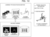
- the multi-viewpoint image in which the 2D-BB have been detected which is output from the region detection apparatus according to the present embodiment, is used for a learning type skeleton recognition of a gymnast or the like, for example, as illustrated in FIG. 12 .
- a skeleton recognition model is generated in advance by machine learning using, as training data, a pair of a multi-viewpoint image in which the 2D-BB is known and a correct answer of a three dimensional coordinate of each joint of a gymnasts represented by the multi-view image (hereinafter, referred to as "3D joint coordinate").
- the skeleton recognition model is, for example, a neural network.
- the multi-viewpoint image in which the 2D-BB have been detected which is output from the region detection apparatus according to the present embodiment
- the multi-viewpoint image is input to the skeleton recognition model that has been subjected to machine learning, and the 3D joint coordinate is output.
- the 3D joint coordinate output from the skeleton recognition model is used as a primary skeleton recognition result, and the 3D joint coordinate in which a position search of each joint position is performed based on a constraint such as a length and a positional relationship between the respective joints is output as a fitting result.
- the present disclosure is not limited thereto.
- a multi-viewpoint image captured by a plurality of cameras which are arranged in substantially the same vertical plane may provide a more accurate recognition result in the skeleton recognition or the like.
- the width of the 3D-BB may be specified based on the width of the 2D-BB detected from the first image and the parameter of the camera that has captured the first image, and the height of the 3D-BB may be estimated based on the width of the 3D-BB and the statistical information related to the three dimensional model of the gymnast.
- each image included in the multi-viewpoint image may be set as the first image
- the other images may be set as the second images
- the 2D-BB detected in the first image may be corrected based on the 2D-BB interpolated in the same manner as in the above-described embodiment.
- the case may be handled in the same manner as in the case where the 2D-BB is not detected in the above-described embodiment.
- the region detection program is stored (installed) in the storage unit in advance, but the present disclosure is not limited thereto.
- the program according to the disclosed technique may be provided in a form stored in a storage medium such as a CD-ROM, a DVD-ROM, or a USB memory.
Landscapes
- Engineering & Computer Science (AREA)
- Physics & Mathematics (AREA)
- General Physics & Mathematics (AREA)
- Theoretical Computer Science (AREA)
- Computer Vision & Pattern Recognition (AREA)
- Multimedia (AREA)
- Geometry (AREA)
- Human Computer Interaction (AREA)
- Image Analysis (AREA)
Abstract
Description
- The present technique relates to a region detection program, a region detection apparatus, and a region detection method.
- Conventionally, there is a technique for recognizing three dimensional information of a person, such as skeletal information of the person, from an image obtained by capturing the person, using a recognition model generated in advance by machine learning. In such a technique, a bounding box surrounding a region of the person to be recognized is detected.
- For example, a 3D model generation apparatus that generates a 3D model of a subject from video captured by a plurality of cameras has been proposed. This apparatus acquires a silhouette image for each viewpoint from a multi-viewpoint video, and generates a low-resolution voxel model having a voxel size of a first size from a plurality of silhouette images by a view volume intersection method. Further, this apparatus classifies the low-resolution voxel model based on a feature thereof, and determines a second size smaller than the first size for each low-resolution voxel model based on a classification result. Further this apparatus generates a high-resolution voxel model having a voxel size of the second size for each 3D bounding box of the low-resolution voxel model, and outputs a 3DCG model of the subject based on the high-resolution voxel model.
- There is also a technique for generating an image of an intermediate viewpoint by estimating corresponding points at another viewpoint from multi-viewpoint image captured from a plurality of viewpoints by using a perspective projection.
- [Patent Document 1]
Japanese Laid-Open Patent Publication No. 2021-071749 - [Non-Patent Document 1] Hideo Saito, Makoto Kimura, Satoshi Yaguchi, Naho Inamoto, "View Interpolation of Multiple Cameras Based on Projective Geometry", 2002.
- When detecting the bounding box as a region indicating a target person from an image by using a machine learning model, a case occurs sometimes in which the bounding box may not be detected or may be erroneously detected. If such non-detection or erroneous detection of the bounding box occurs in any image of the multi-viewpoint image for acquiring the three dimensional information of the person, the three dimensional information may not be accurately acquired in the subsequent processes.
- In addition, for example, in a case where a person who may take various postures such as a gymnast is set as a target, there is a case where it is not possible to appropriately interpolate the bounding box which is not detected or is erroneously detected by simply applying the perspective projection.
- In one aspect, the disclosed technique aims to appropriately interpolate the bounding box which is not detected or is erroneously detected in the multi-viewpoint image.
- As one aspect, the disclosed technique acquires images captured by a plurality of imaging apparatuses that capture a person from different directions. In addition, the disclosed technique inputs the acquired images to a machine learning model generated in advance by machine learning so as to detect a region of the person included in the images, and detects a region indicating the person from each of the acquired images. Further, the disclosed technique interpolates a region indicating the person in a second image of the acquired images based on a region of the person detected from a first image of the acquired images and a parameter of each of the plurality of imaging apparatuses.
- As one aspect, there is an effect that it is possible to appropriately interpolate the bounding box that is not detected or is erroneously detected in the multi-viewpoint image.
-
-
FIG. 1 is a schematic diagram illustrating connection between a region detection apparatus and a camera; -
FIG. 2 is a functional block diagram of the region detection apparatus; -
FIG. 3 is a diagram for explaining a two dimensional bounding box; -
FIG. 4 is a diagram for explaining a difference in width of the two dimensional bounding box depending on a viewpoint; -
FIG. 5 is a diagram for explaining a specification of a person center line in a three dimension; -
FIG. 6 is a diagram for explaining an interpolation of a two dimensional bounding box; -
FIG. 7 is a diagram for explaining a width a height of a three dimensional bounding box; -
FIG. 8 is a diagram for explaining statistical information about the three dimensional bounding box; -
FIG. 9 is a block diagram illustrating a schematic configuration of a computer functioning as the region detection apparatus; -
FIG. 10 is a flowchart illustrating an example of a region detection process; -
FIG. 11 is a diagram illustrating an example of the interpolation of the two dimensional bounding box; and -
FIG. 12 is a diagram for explaining an example of a technique to which a multi-viewpoint image in which the two dimensional bounding box is detected is applied. - Hereinafter, an example of an embodiment according to the disclosed technique will be described with reference to the drawings. In the following embodiment, a case where a target person is a gymnast will be described, but the disclosed technique may be applied to various persons such as players of other sports or general pedestrians.
- As illustrated in
FIG. 1 , theregion detection apparatus 10 according to the present embodiment is coupled to each of a plurality of cameras 30n that capture images of agymnast 90 at viewpoints n from respective different directions. In the example ofFIG. 1 , n = 1, 2, 3, and acamera 301 that captures an image from aviewpoint 1, acamera 302 that captures an image from aviewpoint 2, and acamera 303 that captures an image from aviewpoint 3 are coupled to theregion detection apparatus 10. Note that a number of cameras 30n coupled to theregion detection apparatus 10 is not limited to the example ofFIG. 1 . - The cameras 30n are installed at different positions in substantially the same horizontal plane at an angle at which the
gymnast 90 is within an imaging range. For example, the cameras 30n are arranged horizontally side by side so as to surround thegymnast 90. Note that, here, " substantially in the same horizontal plane " means a case where a height of the camera 30n from a floor surface may be regarded as substantially the same, and a case where a difference in the height of the camera 30n from the floor surface is equal to or less than a predetermined value. A video captured by the camera 30n is sequentially input to theregion detection apparatus 10. Note that time information is associated with each frame included in the video captured by each camera 30n, and the video captured by each camera 30n may be synchronized based on this time information. - As illustrated in
FIG. 2 , theregion detection apparatus 10 functionally includes anacquisition unit 12, adetection unit 14, and aninterpolation unit 16. Further, adetection model 20 is stored in a predetermined storage area of theregion detection apparatus 10. - The acquiring
unit 12 acquires, as a multi-viewpoint image, a set of images indicated by the frame corresponding to the time information in the video input from the camera 30n to theregion detection apparatus 10. Hereinafter, among images included in the multi-viewpoint image, an image captured by the camera 30n is referred to as animage 40n. - The detecting
unit 14 inputs theimage 40n included in the multi-viewpoint image obtained by the obtainingunit 12 to thedetection model 20, and detects a two dimensional boundary box (hereinafter, also referred to as "2D-BB") as a region indicating a person from eachimage 40n. Thedetection model 20 is generated in advance by using, as training data, images in which the correct the 2D-BB is given to images in which gymnasts in various postures are captured. Note that thedetection model 20 is an example of a "machine learning model" of the disclosed technology. For example, as illustrated inFIG. 3 , thedetection unit 14 detects a circumscribed rectangle of a region indicating thegymnast 90 in theimage 40n as 2D-BB42n. - The
interpolation unit 16 interpolates the 2D-BB42n in a second image of the multi-viewpoint image based on a parameter of each camera 30n and the 2D-BB42n detected from a first image of the multi-viewpoint image. In the present embodiment, it is assumed that 2D-BB42k is detected from the image 30k captured by the camera 40k of the viewpoint k, and 2D-BB42_miss is not detected from the image 40_miss captured by the camera 30_miss of the viewpoint_miss. In this case, the image 40k is an example of the first image, and the image 40_miss is an example of the second image. - Here, when the
detection model 20 which is the machine learning model is used as described above, the 2D-BB42n may not be detected or may be erroneously detected from theimage 40n. This may occur when a part of thegymnast 90 in theimage 40n is blocked by an obstacle, when the posture of thegymnast 90 who is a target is not similar to any of gymnasts in the image used for training thedetection model 20, or the like. It is considered that three dimensional information of thegymnast 90 is acquired based on an image in the 2D-BB42n detected from eachimage 40n included in the multi-viewpoint image and a recognition model for recognizing the three dimensional information such as skeleton information generated in advance by machine learning. In this case, if an image in which the 2D-BB42n is not detected or is erroneously detected is included in the multi-viewpoint image, a recognition accuracy of the three dimensional information is reduced. Therefore, it is desirable to interpolate a BB42n that is not detected or is erroneously detected. - However, when a person who may take various postures, such as a gymnast, is a target, there is a case where it is not possible to appropriately interpolate the 2D-BB42n which is not detected or is erroneously detected by simply applying the perspective projection. This will be described in more detail with reference to
FIG. 4 . As illustrated inFIG. 4 , a rectangular parallelepiped having horizontal and vertical surfaces and the smallest rectangular parallelepiped completely surrounding thegymnast 90 in a three dimensional space is assumed as a three dimensional bounding box (hereinafter, also referred to as "3D-BB") 44. At the viewpoint n of each camera 30n, the projection of 3D-BB44 onto eachimage 40n is the 2D-BB42n. - When the cameras 30n are arranged horizontally side by side so as to surround the
gymnast 90, heights (vertical lengths) of the 2D-BB42n in eachimage 40n are the same regardless of the viewpoints of each camera 30n. Note that inFIG. 4 , the heights of the 2D-BB42n and the heights of the 3D-BB44 are represented by lines coupling stars. On the other hand, widths (horizontal lengths) of the 2D-BB42n in eachimage 40n are different depending on the viewpoints of each camera 30n. In the example ofFIG. 4 , the width of the 2D-BB421 detected from animage 401 and the width of the 2D-BB422 detected from animage 402 are different due to the difference in the viewpoints. Therefore, for example, since the 2D-BB423 is not detected in animage 403, even if the perspective projection as in the related art is simply applied to interpolate from the detected the 2D-BB421 and the 2D-BB422, the widths of the 2D-BB423 may not be appropriately determined. Therefore, the 2D-BB423 in theimage 403 cannot be interpolated. - Therefore, the
interpolation unit 16 specifies the height of the 2D-BB42_miss in the image 40_miss in which the 2D-BB is not detected based on the height of 2D-BB42k in the image 40k in which the 2D-BB is detected and each parameter of the camera 30k. Then, theinterpolation unit 16 estimates the width of the 2D-BB42_miss in the image 40_miss in which the 2D-BB is not detected, based on statistical information on the posture of thegymnast 90 and the parameter of the camera 30_miss. - The description will be made in detail with reference to
FIGS. 5 and6 . Theinterpolation unit 16 sets 2D-BB42k detected from the image 40k as Bk = [xk, yk, wk, hk] . xk and yk are coordinates in the image 40k of a point at the upper left corner of 2D-BB42k, and w and h are the width and height of 2D-BB42k, respectively. Further, theinterpolation unit 16 also sets the 2DandBB42_miss in the image 40_miss to Bmiss = [xmiss, ymiss, wmiss, hmiss]. For example, identifying the Bmiss corresponds to interpolating the 2D-BB42_miss. Note that, in the examples ofFIGS. 5 and6 , "k = 1, 2,"is established and "_miss = 3" is established. - The
interpolation unit 16 specifies a coordinate [xk+wk/2, yk] of an upper end point of a vertical center line of 2D-BB42k and a coordinate [xk+wk/2, yk+hk] of a lower end point. Then, theinterpolation unit 16 converts the coordinates of the upper end point and the lower end point into three dimensional coordinates by using the parameter of the camera 30k for converting the three dimensional coordinates into coordinates on an image plane captured by the camera 30k. For example, theinterpolator 16 may convert the coordinates using cv::sfm::trianglePoints defined in OpenCV (https://docs.opencv.org/3.4/d0/dbd/group triangulation.html). In this case, theinterpolation unit 16 calculates the three dimensional coordinates of points P3dtop and P3dbot in the three dimensional space corresponding to the upper end point and the lower end point, respectively, as illustrated in the following Equations (1) and (2) using a parameter matrix ProjMatcam_k of the camera 30k. Note that a line coupling P3dtop and the P3dbot in the three dimensional space is referred to as a person center line.

- Further, the
interpolation unit 16 converts the three dimensional coordinates of the P3dtop and P3dbot into coordinates on the image 40_miss based on the parameter of the camera 30_miss, as illustrated inFIG. 6 . Thus, theinterpolation unit 16 calculates the coordinates of an upper end point and a lower end point of a vertical center line between the 2D-BB42_miss. For example, theinterpolation unit 16 performs a coordinate conversion as illustrated in the following Equations (3) and (4) using a parameter matrix ProjMatcam_miss of the camera 30_miss and a parameter s representing a scale ratio between the three dimensional coordinates and a size of the image 40.

- The
interpolation unit 16 calculates ymiss, hmiss, and xmiss+wmiss/2 for specifying the coordinates of the upper end point and the lower end point of the vertical center line of 2D-BB42_miss based on the above-described coordinate conversion as illustrated in the following Equations (5) to (7).


- The
interpolation unit 16 specifies a line coupling the specified upper end point and the specified lower end point as the vertical center line of the 2D-BB42_miss, and specifies a length of the vertical center line as the height of the 2D-BB42_miss. - Further, the
interpolation unit 16 estimates the width of the 2D-BB42_miss based on the specified height of the 2D-BB42_miss and the statistical information related to the posture of thegymnast 90. The statistical information may be, for example, a mean of a sum of the height and the width of the 3D-BB44 surrounding the gymnast in each of the cases where the gymnast takes a plurality of different postures. In the following description, as illustrated inFIG. 7 , the height of the 3D-BB44 is represented by Height_3D, the larger one of the widths is represented by Width_max_3D, and the smaller one is represented by Width_min_3D. - The statistical information will be described in more detail. First, as illustrated in
FIG. 8 , a three dimensional model of a full-size gymnast are prepared for a plurality of postures (poses), which are acquired from a motion capture, a manual annotation, published data, and the like. In the example ofFIG. 8 , three dimensional models for M poses are prepared. Then, the 3D-BB44 is specified for each three dimensional model, each of the Height_3D, the Width_max_3D, and the Width_min_3D is calculated, and a mean Mean_3D illustrated in the following Equation (8) is calculated as the statistical information.
- The
interpolation unit 16 calculates Width_3D of the 3D-BB44 of thegymnast 90 who is the target as illustrated in the following Equation (9) using the above-described statistical information Mean_3D and the Ztop and Zbot which have been already calculated.
- When perspectively projecting the 3D-BB onto the image, a ratio of the height and the width of the projected the 2D-BB is similar to a ratio of the height and the width of the 3D-BB before the projecting. Therefore, the
interpolation unit 16 calculates the width wmiss of the 2D-BB42_miss as illustrated in the following Equation (10) using the calculated Width_3D and the already-calculated Ztop, Zbot, and hmiss. Further, theinterpolation unit 16 calculates the xmiss by the calculated wmiss and Equation (7) as illustrated in Equation (11) below.

- The
interpolation unit 16 interpolates the 2D-BB42_miss specified by [xmiss, ymiss, wmiss, hmiss] calculated by Equations (5), (6), (10), and (11) in the image 40_miss. Then, theinterpolation unit 16 outputs the interpolated 2D-BB42_miss and 2D-BB42k together as a multi-viewpoint image in which the 2D-BB has been detected. - The
region detection apparatus 10 may be implemented by, for example, acomputer 50 illustrated inFIG. 9 . Thecomputer 50 includes a central processing unit (CPU) 51, amemory 52 as a temporary storage area, and anonvolatile storage unit 53. Thecomputer 50 further includes an input/output interface (I/F) 54 to which external devices such as a camera 30n, an input device, and a display are coupled, and a read/write (R/W)unit 55 that controls reading and writing of data from and to astorage media 59. Further, thecomputer 50 includes a communication I/F 56 coupled to a network such as a Internet. TheCPU 51, thememory 52, thestorage unit 53, the input/output I/F 54, the R/W unit 55, and the communication I/F 56 are coupled to each other via abus 57. - The
storage unit 53 may be realized by a hard disk drive (HDD), a solid state drive (SSD), a flash memory, or the like. Thestorage unit 53 as a storage medium stores anarea detection program 60 for causing thecomputer 50 to function as thearea detection apparatus 10. Theregion detection program 60 includes anacquisition process 62, adetection process 64, and aninterpolation process 66. Further, hestorage unit 53 includes aninformation storage area 70 in which information constituting thedetection model 20 is stored. - The
CPU 51 reads theregion detection program 60 from thestorage unit 53, develops theregion detection program 60 in thememory 52, and sequentially executes processes included in theregion detection program 60. TheCPU 51 operates as theacquisition unit 12 illustrated inFIG. 2 by executing theacquisition process 62. Further, theCPU 51 operates as thedetection unit 14 illustrated inFIG. 2 by executing thedetection process 64. Further, theCPU 51 operates as theinterpolation unit 16 illustrated inFIG. 2 by executing theinterpolation process 66. Further, theCPU 51 reads information from theinformation storage area 70 and develops thedetection model 20 in thememory 52. Thus, thecomputer 50 that executes theregion detection program 60 functions as theregion detection apparatus 10. Note that theCPU 51 that executes the program is hardware. - Note that functions implemented by the
region detection program 60 may be implemented by, for example, a semiconductor integrated circuit, for example, a graphics processing unit (GPU), an application specific integrated circuit (ASIC), or the like. - Next, an operation of the
region detection apparatus 10 according to the present embodiment will be described. When a multi-viewpoint image is input from the camera 30n to theregion detection apparatus 10, theregion detection apparatus 10 performs a region detection process illustrated inFIG. 10 . Note that the region detection process is an example of a region detection method of the disclosed technique. - In step S10, the
acquisition unit 12 acquires a multi-viewpoint image input to theregion detection apparatus 10. Next, in step S12, thedetection unit 14 inputs eachimage 40n included in the acquired multi-viewpoint image to thedetection model 20, and detects the 2D-BB42n from eachimage 40n. Next, in step S14, thedetection unit 14 determines whether or not there is animage 40n in which the 2D-BB42n is not detected among theimages 40n included in the multi-viewpoint image. If there is animage 40n in which the 2D-BB42n are not detected, the process proceeds to step S16, and if there is noimage 40n in which the 2D-BB42n is not detected, the process proceeds to step S24. - In step S16, the
interpolation unit 16 specifies the coordinate [xk+wk/2, yk] of the upper end point of the vertical center line of the detected 2D-BB42k and the coordinate [xk+wk/2, yk+hk] of the lower end point of the vertical center line. Next, in step S18, theinterpolation unit 16 specifies the points P3dtop and P3dbot obtained by converting the coordinates of the upper end point and the lower end point into the three dimensional coordinates using the parameter matrix of the camera 30k (denoted as "OK camera" inFIG. 10 ). Then, theinterpolation unit 16 specifies the line coupling the P3dtop and the P3dbot as the person center line. - Next, in step S20, the
interpolation unit 16 projects the three dimensional coordinates of the P3dtop and P3dbot onto the image 40_miss (denoted as "miss image" inFIG. 10 ) based on the parameter matrix of the camera 30_miss (denoted as "miss camera" inFIG. 10 ). Thus, the vertical center line of the 2D-BB42_miss is specified, and the length of the vertical center line is specified as the height of the 2D-BB42_miss. - Next, in step S22, the
interpolation unit 16 estimates the width of the 2D-BB42_miss based on the specified height of the 2D-BB42_miss and the statistical information about the posture of thegymnast 90. Thus, the 2D-BB42_miss specified by the vertical center line and the height of the 2D-BB42_miss which are specified in step S20 and the width of the 2D-BB42_miss which is estimated in this step are interpolated in the image 40_miss. - Next, in step S24, the
interpolation unit 16 outputs a multi-viewpoint image in which the 2D-BB42n is detected from eachimage 40n. The detected 2D-BB42n includes the 2D-BB interpolated in the above step S22. Next, in step S26, theacquisition unit 12 determines whether or not a next multi-viewpoint image is input to theregion detection apparatus 10. When the next multi-viewpoint image is input to theregion detection apparatus 10, the process returns to step S10, and when the next multi-viewpoint image is not input, the region detection process is terminated. -
FIG. 11 illustrates an example of an interpolation of the 2D-BB that has not been detected in a multi-viewpoint image including four images. InFIG. 11 , cam_id:n (n=1,2,3,4) represents an image captured by a camera having an id of n. Further, frame:852 is a frame number associated with each image, and corresponds to the time information in the above-described embodiment. 2D_BB that is missing in cam_id:3 included in the multi-viewpoint image of aframe number 852 as illustrated in the left diagram ofFIG. 11 is interpolated as illustrated in the right diagram ofFIG. 11 by applying the present embodiment. - As described above, the region detection apparatus according to the present embodiment acquires a multi-viewpoint image that is a set of images captured by a plurality of cameras that capture a person from each different direction. The region detection apparatus inputs each of the images included in the acquired multi-viewpoint image to a detection model generated in advance by machine learning so as to detect a bounding box indicating a region of the person included in the image, and detects the bounding box from each of the images. Then, the region detection apparatus interpolates, based on the bounding box detected from a first image among the acquired images and the parameter of each of the plurality of cameras, the bounding box in a second image among the acquired images.
- For example, the region detection apparatus projects the detected 2D-BB from a two dimension to a three dimension using internal and external parameters of the camera, and determines a vertical person center line in the three dimensional space. Further, the region detection apparatus estimates a width of the 3D-BB based on statistical information indicating a mean of the height and width of the 3D-BB and the height of the 3D-BB which is the length of the person center line, which are calculated in advance from the three dimensional model of gymnasts in various postures. Further, the region detection apparatus interpolates the 2D-BB in the image by projecting the 3D_BB specified from the person center line and the height and width of the 3D-BB from the three dimension to the two dimension using the internal and external parameters of the camera. Thus, the undetected bounding box in the multi-viewpoint image may be appropriately interpolated.
- The multi-viewpoint image in which the 2D-BB have been detected, which is output from the region detection apparatus according to the present embodiment, is used for a learning type skeleton recognition of a gymnast or the like, for example, as illustrated in
FIG. 12 . In the example ofFIG. 12 , a skeleton recognition model is generated in advance by machine learning using, as training data, a pair of a multi-viewpoint image in which the 2D-BB is known and a correct answer of a three dimensional coordinate of each joint of a gymnasts represented by the multi-view image (hereinafter, referred to as "3D joint coordinate"). The skeleton recognition model is, for example, a neural network. Then, when the multi-viewpoint image in which the 2D-BB have been detected, which is output from the region detection apparatus according to the present embodiment, is acquired as a multi-viewpoint image of a gymnast to be recognized, the multi-viewpoint image is input to the skeleton recognition model that has been subjected to machine learning, and the 3D joint coordinate is output. Then, the 3D joint coordinate output from the skeleton recognition model is used as a primary skeleton recognition result, and the 3D joint coordinate in which a position search of each joint position is performed based on a constraint such as a length and a positional relationship between the respective joints is output as a fitting result. - Further, in the above embodiment, the case where the plurality of cameras are arranged in substantially the same horizontal plane has been described, but the present disclosure is not limited thereto. For example, depending on a game played by a player, a multi-viewpoint image captured by a plurality of cameras which are arranged in substantially the same vertical plane may provide a more accurate recognition result in the skeleton recognition or the like. In this case, the width of the 3D-BB may be specified based on the width of the 2D-BB detected from the first image and the parameter of the camera that has captured the first image, and the height of the 3D-BB may be estimated based on the width of the 3D-BB and the statistical information related to the three dimensional model of the gymnast.
- Further, in the above-described embodiment, the case where the first image is an image in which the 2D-BB is detected and the second image is an image in which 2D-BB is not detected, for example, the case where the 2D-BB is interpolated in an image in which the 2D-BB is missing has been described, but the present disclosure is not limited thereto. For example, each image included in the multi-viewpoint image may be set as the first image, the other images may be set as the second images, and the 2D-BB detected in the first image may be corrected based on the 2D-BB interpolated in the same manner as in the above-described embodiment. In addition, in a case where the detection model outputs, together with a detection of the bounding box, reliability of the detection and the reliability of the detection is equal to or less than a predetermined value, the case may be handled in the same manner as in the case where the 2D-BB is not detected in the above-described embodiment.
- Further, in the above-described embodiment, the region detection program is stored (installed) in the storage unit in advance, but the present disclosure is not limited thereto. The program according to the disclosed technique may be provided in a form stored in a storage medium such as a CD-ROM, a DVD-ROM, or a USB memory.
-
- 10
- Region detection apparatus
- 12
- Acquisition unit
- 14
- Detection unit
- 16
- Interpolation unit
- 20
- Detection model
- 301, 302, 303
- Camera
- 401, 402, 403
- Image
- 421, 422
- 2D-BB
- 50
- Computer
- 51
- CPU
- 52
- Memory
- 53
- Storage unit
- 59
- Storage medium
- 60
- Region detection program
Claims (20)
- A region detection program for causing a computer to execute a process comprising:acquiring images each which is captured by each of a plurality of imaging apparatuses that capture the respective images of a person from respective different directions;detecting a region indicating the person from each of the images by inputting the images to a machine learning model which is generated in advance by a machine learning so as to detect the region indicating the person; andinterpolating, based on a first region of the person which is detected from a first image of the images and a parameter of each of the plurality of imaging apparatuses, a second region indicating the person in a second image of the images.
- The region detection program according to claim 1, whereinthe first image is an image in which the region indicating the person is detected by the machine learning model in the images, andthe second image is an image in which the region indicating the person is not detected by the machine learning model in the images.
- The region detection program according to claim 2, whereinthe plurality of imaging apparatuses are arranged in a same horizontal plane, anda width of the second program is estimated based on a height of the first region, a height of the second region, and statistical information regarding a posture of the person.
- The region detection program according to claim 3, wherein
the height of the second region is estimated by converting an end point of a vertical center line of the first region into a coordinate of an end point of a vertical center line of the person in a three dimensional space based on the parameter of an imaging apparatus which captures the first image and converting the coordinate into a coordinate in the second image based on the parameter of an imaging apparatus which captures the second image. - The region detection program according to claim 4, wherein the statistical information regarding the posture of the person is a mean of a sum of a height and a width of a rectangular parallelepiped surrounding the person in each of a plurality of different postures of the person
- The region detection program according to claim 5, wherein
a length of the vertical center line of the person in the three dimensional space is set as a height of the person in the three dimensional space, a difference between the mean indicated by the statistical information and the height of the person in the three dimensional space is estimated as a width of the person in the three dimensional space and the width of the second region is estimated based on a ratio of the height and the width of the person in the three dimensional space and the height of the second region. - The region detection program according to claim 2, whereinthe plurality of imaging apparatuses are arranged in a same vertical plane, anda height of the second region is estimated based on a width of the first region, a width of the second region, and statistical information regarding a posture of the person.
- A region detection apparatus comprising:an acquisition unit configured to acquire images each which is captured by each of a plurality of imaging apparatuses that capture the respective images of a person from respective different directions;a detection unit configured to detect a region indicating the person from each of the images by inputting the images to a machine learning model which is generated in advance by a machine learning so as to detect the region indicating the person; andan interpolation unit configured to interpolate, based on a first region of the person which is detected from a first image of the images and a parameter of each of the plurality of imaging apparatuses, a second region indicating the person in a second image of the images.
- The region detection apparatus according to claim 8, whereinthe first image is an image in which the region indicating the person is detected by the machine learning model in the images, andthe second image is an image in which the region indicating the person is not detected by the machine learning model in the images.
- The region detection apparatus according to claim 9, whereinthe plurality of imaging apparatuses are arranged in a same horizontal plane, anda width of the second region is estimated based on a height of the first region, a height of the second region, and statistical information regarding a posture of the person.
- The region detection apparatus according to claim 10, wherein
the height of the second region is estimated by converting an end point of a vertical center line of the first region into a coordinate of an end point of a vertical center line of the person in a three dimensional space based on the parameter of an imaging apparatus which captures the first image and converting the coordinate into a coordinate in the second image based on the parameter of an imaging apparatus which captures the second image. - The region detection apparatus according to claim 11, wherein
the statistical information regarding the posture of the person is a mean of a sum of a height and a width of a rectangular parallelepiped surrounding the person in each of a plurality of different postures of the person. - The region detection apparatus according to claim 12, wherein
a length of the vertical center line of the person in the three dimensional space is set as a height of the person in the three dimensional space, a difference between the mean indicated by the statistical information and the height of the person in the three dimensional space is estimated as a width of the person in the three dimensional space and the width of the second region is estimated based on a ratio of the height and the width of the person in the three dimensional space and the height of the second region. - The region detection apparatus according to claim 9, whereinthe plurality of imaging apparatuses are arranged in a same vertical plane, anda height of the second region is estimated based on a width of the first region, a width of the second region, and statistical information regarding a posture of the person.
- A region detection method for executing a process comprising:acquiring images each which is captured by each of a plurality of imaging apparatuses that capture the respective images of a person from respective different directions;detecting a region indicating the person from each of the images by inputting the images to a machine learning model which is generated in advance by a machine learning so as to detect the region indicating the person; andinterpolating, based on a first region of the person which is detected from a first image of the images and a parameter of each of the plurality of imaging apparatuses, a second region indicating the person in a second image of the images.
- The region detection method according to claim 15, whereinthe first image is an image in which the region indicating the person is detected by the machine learning model in the images, andthe second image is an image in which the region indicating the person is not detected by the machine learning model in the images.
- The region detection method according to claim 16, whereinthe plurality of imaging apparatuses are arranged in a same horizontal plane, anda width of the second method is estimated based on a height of the first region, a height of the second region, and statistical information regarding a posture of the person.
- The region detection method according to claim 17, wherein
the height of the second region is estimated by converting an end point of a vertical center line of the first region into a coordinate of an end point of a vertical center line of the person in a three dimensional space based on the parameter of an imaging apparatus which captures the first image and converting the coordinate into a coordinate in the second image based on the parameter of an imaging apparatus which captures the second image. - The region detection method according to claim 18, wherein
the statistical information regarding the posture of the person is a mean of a sum of a height and a width of a rectangular parallelepiped surrounding the person in each of a plurality of different postures of the person. - A non-transitory computer-readable recording medium storing a region detection program for causing a computer to execute a process comprising:acquiring images each which is captured by each of a plurality of imaging apparatuses that capture the respective images of a person from respective different directions;detecting a region indicating the person from each of the images by inputting the images to a machine learning model which is generated in advance by a machine learning so as to detect the region indicating the person; andinterpolating, based on a first region of the person which is detected from a first image of the images and a parameter of each of the plurality of imaging apparatuses, a second region indicating the person in a second image of the images.
Applications Claiming Priority (1)
| Application Number | Priority Date | Filing Date | Title |
|---|---|---|---|
| PCT/JP2021/037958 WO2023062760A1 (en) | 2021-10-13 | 2021-10-13 | Region detection program, device, and method |
Publications (2)
| Publication Number | Publication Date |
|---|---|
| EP4418203A1 true EP4418203A1 (en) | 2024-08-21 |
| EP4418203A4 EP4418203A4 (en) | 2024-11-27 |
Family
ID=85987320
Family Applications (1)
| Application Number | Title | Priority Date | Filing Date |
|---|---|---|---|
| EP21960618.3A Pending EP4418203A4 (en) | 2021-10-13 | 2021-10-13 | AREA DETECTION PROGRAM, APPARATUS AND METHOD |
Country Status (5)
| Country | Link |
|---|---|
| US (1) | US20240242464A1 (en) |
| EP (1) | EP4418203A4 (en) |
| JP (1) | JP7639931B2 (en) |
| CN (1) | CN118043856A (en) |
| WO (1) | WO2023062760A1 (en) |
Families Citing this family (1)
| Publication number | Priority date | Publication date | Assignee | Title |
|---|---|---|---|---|
| CN120558098B (en) * | 2025-05-30 | 2026-03-10 | 内蒙古师范大学 | Sheep body ruler measuring method, equipment, medium and program product based on three-dimensional reconstruction and point cloud segmentation |
Family Cites Families (12)
| Publication number | Priority date | Publication date | Assignee | Title |
|---|---|---|---|---|
| JP3814779B2 (en) | 2001-03-27 | 2006-08-30 | 三菱電機株式会社 | Intruder automatic tracking method and apparatus, and image processing apparatus |
| US9692964B2 (en) * | 2003-06-26 | 2017-06-27 | Fotonation Limited | Modification of post-viewing parameters for digital images using image region or feature information |
| JP2009025874A (en) | 2007-07-17 | 2009-02-05 | Nec Corp | Face image registration device, face discrimination device, face image registration method, face identification method and face image registration program |
| JP2009143722A (en) | 2007-12-18 | 2009-07-02 | Mitsubishi Electric Corp | Person tracking device, person tracking method, and person tracking program |
| US9877012B2 (en) * | 2015-04-01 | 2018-01-23 | Canon Kabushiki Kaisha | Image processing apparatus for estimating three-dimensional position of object and method therefor |
| US10885396B2 (en) * | 2017-05-24 | 2021-01-05 | Amazon Technologies, Inc. | Generating composite images using audio/video recording and communication devices |
| US11113887B2 (en) * | 2018-01-08 | 2021-09-07 | Verizon Patent And Licensing Inc | Generating three-dimensional content from two-dimensional images |
| US20190356885A1 (en) * | 2018-05-16 | 2019-11-21 | 360Ai Solutions Llc | Camera System Securable Within a Motor Vehicle |
| US11804045B2 (en) * | 2019-01-11 | 2023-10-31 | Nec Corporation | Monitoring device, monitoring method, and recording medium |
| JP7290546B2 (en) | 2019-10-29 | 2023-06-13 | Kddi株式会社 | 3D model generation apparatus and method |
| CN114746900B (en) * | 2019-11-20 | 2025-10-28 | 松下知识产权经营株式会社 | Three-dimensional model generation method and three-dimensional model generation device |
| JP2021152724A (en) | 2020-03-24 | 2021-09-30 | キヤノン株式会社 | Information processing apparatus, information processing method, and program |
-
2021
- 2021-10-13 WO PCT/JP2021/037958 patent/WO2023062760A1/en not_active Ceased
- 2021-10-13 EP EP21960618.3A patent/EP4418203A4/en active Pending
- 2021-10-13 JP JP2023553831A patent/JP7639931B2/en active Active
- 2021-10-13 CN CN202180102809.3A patent/CN118043856A/en active Pending
-
2024
- 2024-03-13 US US18/603,752 patent/US20240242464A1/en active Pending
Also Published As
| Publication number | Publication date |
|---|---|
| EP4418203A4 (en) | 2024-11-27 |
| US20240242464A1 (en) | 2024-07-18 |
| CN118043856A (en) | 2024-05-14 |
| JP7639931B2 (en) | 2025-03-05 |
| WO2023062760A1 (en) | 2023-04-20 |
| JPWO2023062760A1 (en) | 2023-04-20 |
Similar Documents
| Publication | Publication Date | Title |
|---|---|---|
| US11727637B2 (en) | Method for generating 3D skeleton using joint-based calibration acquired from multi-view camera | |
| US8803950B2 (en) | Three-dimensional face capturing apparatus and method and computer-readable medium thereof | |
| US9715761B2 (en) | Real-time 3D computer vision processing engine for object recognition, reconstruction, and analysis | |
| US8447099B2 (en) | Forming 3D models using two images | |
| JP5328979B2 (en) | Object recognition method, object recognition device, autonomous mobile robot | |
| US8452081B2 (en) | Forming 3D models using multiple images | |
| US20120306874A1 (en) | Method and system for single view image 3 d face synthesis | |
| KR101682656B1 (en) | 3 Dimension Face Capturing Apparatus and Method thereof | |
| JP2011198330A (en) | Method and program for collation in three-dimensional registration | |
| CN106503684A (en) | A kind of face image processing process and device | |
| CN105723180A (en) | Mobile body position estimation device and mobile body position estimation method | |
| JP2005326247A (en) | Calibration apparatus, calibration method, and calibration program | |
| EP3300025B1 (en) | Image processing device and image processing method | |
| US20230368415A1 (en) | Skeleton recognition method, non-transitory computer-readable recording medium, and gymnastics scoring assist system | |
| US20240242464A1 (en) | Computer-readable recording medium storing region detection program, apparatus, and method | |
| WO2021100681A1 (en) | Three-dimensional model generation method and three-dimensional model generation device | |
| US11145048B2 (en) | Image processing apparatus, image processing method, and non-transitory computer-readable storage medium for storing program | |
| JP2009237846A (en) | Information processor, information processing method, and computer program | |
| US20200193637A1 (en) | Image processing apparatus and image processing method | |
| JP4389663B2 (en) | Image processing method and image processing apparatus | |
| JP7059701B2 (en) | Estimator, estimation method, and estimation program | |
| JP2005309782A (en) | Image processing device | |
| US12423934B2 (en) | Image processing apparatus, image processing method, and storage medium | |
| JP7754315B2 (en) | Three-dimensional position calculation method, device, and program | |
| US12518411B2 (en) | Image processing apparatus, image processing method, and storage medium |
Legal Events
| Date | Code | Title | Description |
|---|---|---|---|
| STAA | Information on the status of an ep patent application or granted ep patent |
Free format text: STATUS: THE INTERNATIONAL PUBLICATION HAS BEEN MADE |
|
| PUAI | Public reference made under article 153(3) epc to a published international application that has entered the european phase |
Free format text: ORIGINAL CODE: 0009012 |
|
| STAA | Information on the status of an ep patent application or granted ep patent |
Free format text: STATUS: REQUEST FOR EXAMINATION WAS MADE |
|
| 17P | Request for examination filed |
Effective date: 20240313 |
|
| AK | Designated contracting states |
Kind code of ref document: A1 Designated state(s): AL AT BE BG CH CY CZ DE DK EE ES FI FR GB GR HR HU IE IS IT LI LT LU LV MC MK MT NL NO PL PT RO RS SE SI SK SM TR |
|
| A4 | Supplementary search report drawn up and despatched |
Effective date: 20241028 |
|
| RIC1 | Information provided on ipc code assigned before grant |
Ipc: G06T 7/593 20170101ALI20241022BHEP Ipc: G06T 7/00 20170101AFI20241022BHEP |
|
| DAV | Request for validation of the european patent (deleted) | ||
| DAX | Request for extension of the european patent (deleted) | ||
| STAA | Information on the status of an ep patent application or granted ep patent |
Free format text: STATUS: EXAMINATION IS IN PROGRESS |
|
| 17Q | First examination report despatched |
Effective date: 20251203 |
|
| GRAP | Despatch of communication of intention to grant a patent |
Free format text: ORIGINAL CODE: EPIDOSNIGR1 |
|
| STAA | Information on the status of an ep patent application or granted ep patent |
Free format text: STATUS: GRANT OF PATENT IS INTENDED |