EP4418199A1 - Image generation method - Google Patents
Image generation method Download PDFInfo
- Publication number
- EP4418199A1 EP4418199A1 EP24153896.6A EP24153896A EP4418199A1 EP 4418199 A1 EP4418199 A1 EP 4418199A1 EP 24153896 A EP24153896 A EP 24153896A EP 4418199 A1 EP4418199 A1 EP 4418199A1
- Authority
- EP
- European Patent Office
- Prior art keywords
- region
- reduced
- partial images
- observation
- image
- Prior art date
- Legal status (The legal status is an assumption and is not a legal conclusion. Google has not performed a legal analysis and makes no representation as to the accuracy of the status listed.)
- Granted
Links
Images






Classifications
-
- G—PHYSICS
- G06—COMPUTING OR CALCULATING; COUNTING
- G06T—IMAGE DATA PROCESSING OR GENERATION, IN GENERAL
- G06T3/00—Geometric image transformations in the plane of the image
- G06T3/40—Scaling of whole images or parts thereof, e.g. expanding or contracting
- G06T3/4038—Image mosaicing, e.g. composing plane images from plane sub-images
-
- G—PHYSICS
- G06—COMPUTING OR CALCULATING; COUNTING
- G06T—IMAGE DATA PROCESSING OR GENERATION, IN GENERAL
- G06T3/00—Geometric image transformations in the plane of the image
- G06T3/40—Scaling of whole images or parts thereof, e.g. expanding or contracting
-
- G—PHYSICS
- G06—COMPUTING OR CALCULATING; COUNTING
- G06T—IMAGE DATA PROCESSING OR GENERATION, IN GENERAL
- G06T7/00—Image analysis
- G06T7/10—Segmentation; Edge detection
- G06T7/11—Region-based segmentation
-
- H—ELECTRICITY
- H04—ELECTRIC COMMUNICATION TECHNIQUE
- H04N—PICTORIAL COMMUNICATION, e.g. TELEVISION
- H04N1/00—Scanning, transmission or reproduction of documents or the like, e.g. facsimile transmission; Details thereof
- H04N1/387—Composing, repositioning or otherwise geometrically modifying originals
- H04N1/3876—Recombination of partial images to recreate the original image
-
- H—ELECTRICITY
- H04—ELECTRIC COMMUNICATION TECHNIQUE
- H04N—PICTORIAL COMMUNICATION, e.g. TELEVISION
- H04N1/00—Scanning, transmission or reproduction of documents or the like, e.g. facsimile transmission; Details thereof
- H04N1/387—Composing, repositioning or otherwise geometrically modifying originals
- H04N1/393—Enlarging or reducing
-
- H—ELECTRICITY
- H04—ELECTRIC COMMUNICATION TECHNIQUE
- H04N—PICTORIAL COMMUNICATION, e.g. TELEVISION
- H04N23/00—Cameras or camera modules comprising electronic image sensors; Control thereof
- H04N23/60—Control of cameras or camera modules
- H04N23/698—Control of cameras or camera modules for achieving an enlarged field of view, e.g. panoramic image capture
-
- H—ELECTRICITY
- H04—ELECTRIC COMMUNICATION TECHNIQUE
- H04N—PICTORIAL COMMUNICATION, e.g. TELEVISION
- H04N23/00—Cameras or camera modules comprising electronic image sensors; Control thereof
- H04N23/80—Camera processing pipelines; Components thereof
-
- H—ELECTRICITY
- H04—ELECTRIC COMMUNICATION TECHNIQUE
- H04N—PICTORIAL COMMUNICATION, e.g. TELEVISION
- H04N5/00—Details of television systems
- H04N5/222—Studio circuitry; Studio devices; Studio equipment
- H04N5/262—Studio circuits, e.g. for mixing, switching-over, change of character of image, other special effects ; Cameras specially adapted for the electronic generation of special effects
- H04N5/2624—Studio circuits, e.g. for mixing, switching-over, change of character of image, other special effects ; Cameras specially adapted for the electronic generation of special effects for obtaining an image which is composed of whole input images, e.g. splitscreen
-
- H—ELECTRICITY
- H04—ELECTRIC COMMUNICATION TECHNIQUE
- H04N—PICTORIAL COMMUNICATION, e.g. TELEVISION
- H04N5/00—Details of television systems
- H04N5/222—Studio circuitry; Studio devices; Studio equipment
- H04N5/262—Studio circuits, e.g. for mixing, switching-over, change of character of image, other special effects ; Cameras specially adapted for the electronic generation of special effects
- H04N5/265—Mixing
-
- G—PHYSICS
- G06—COMPUTING OR CALCULATING; COUNTING
- G06T—IMAGE DATA PROCESSING OR GENERATION, IN GENERAL
- G06T2207/00—Indexing scheme for image analysis or image enhancement
- G06T2207/10—Image acquisition modality
- G06T2207/10056—Microscopic image
-
- G—PHYSICS
- G06—COMPUTING OR CALCULATING; COUNTING
- G06T—IMAGE DATA PROCESSING OR GENERATION, IN GENERAL
- G06T2207/00—Indexing scheme for image analysis or image enhancement
- G06T2207/20—Special algorithmic details
- G06T2207/20021—Dividing image into blocks, subimages or windows
-
- G—PHYSICS
- G06—COMPUTING OR CALCULATING; COUNTING
- G06T—IMAGE DATA PROCESSING OR GENERATION, IN GENERAL
- G06T2207/00—Indexing scheme for image analysis or image enhancement
- G06T2207/20—Special algorithmic details
- G06T2207/20212—Image combination
- G06T2207/20221—Image fusion; Image merging
-
- G—PHYSICS
- G06—COMPUTING OR CALCULATING; COUNTING
- G06T—IMAGE DATA PROCESSING OR GENERATION, IN GENERAL
- G06T2207/00—Indexing scheme for image analysis or image enhancement
- G06T2207/30—Subject of image; Context of image processing
- G06T2207/30004—Biomedical image processing
- G06T2207/30024—Cell structures in vitro; Tissue sections in vitro
-
- G—PHYSICS
- G06—COMPUTING OR CALCULATING; COUNTING
- G06T—IMAGE DATA PROCESSING OR GENERATION, IN GENERAL
- G06T2207/00—Indexing scheme for image analysis or image enhancement
- G06T2207/30—Subject of image; Context of image processing
- G06T2207/30004—Biomedical image processing
- G06T2207/30072—Microarray; Biochip, DNA array; Well plate
Definitions
- the present invention relates to a technique for generating an observation image by combining a plurality of images obtained by image capture.
- Imaging devices have conventionally been known that capture images of cells incubated in a specimen container such as a well plate at high resolutions.
- a specimen container such as a well plate
- Japanese Patent Application Laid-Open No. 2017-161385 discloses such a conventional imaging device.
- This type of imaging device generates a single observation image by segmenting a specimen container into a plurality of regions, capturing an image of each region, and combining the captured images.
- the images of the specimen container are to be captured at higher magnifications and higher resolutions, the size of data to be handled in image composition processing will increase.
- a computer that performs the image composition processing requires large-capacity memory.
- the increased size of data to be handled makes it difficult to perform the image composition processing at high speed.
- the present invention has been made in light of such circumstances, and it is an object of the present invention to provide a technique for reducing storage capacity required for memory in processing for generating an observation image by combining a plurality of images obtained by image capture.
- a first aspect of the present application is an image generation method of generating an observation image from a plurality of partial images obtained by segmenting an imaging region including an object to be observed into a plurality of regions and capturing images of the plurality of regions, the observation image being a composite image of an observation region that is smaller than the imaging region.
- the image generation method causes a computer including memory to execute (a) generating a plurality of reduced partial images by reducing the plurality of partial images, (b) combining the plurality of reduced partial images into a reduced composite image, (c) detecting a reduced observation region that corresponds to the observation region from the reduced composite image, (d) calculating the observation region that is not reduced, in accordance with the reduced observation region, and (e) generating the observation image by combining, among the plurality of partial images, partial images that correspond to the observation region.
- a second aspect of the present application is the image generation method according to the first aspect, in which after the operation (d), among the plurality of partial images, partial images that do not correspond to the observation region are deleted from the memory.
- a fourth aspect of the present application is the image generation method according to the third aspect, in which after the operation (e-2), the partial images that correspond to the first segmented region are deleted from the memory.
- a fifth aspect of the present application is the image generation method according to any one of the first to fourth aspects, in which the operation (c) further includes detecting a reduced region of interest that corresponds to a region of interest from the observation region, and the operation (d) further includes calculating the region of interest that is not reduced, in accordance with the reduced region of interest.
- the observation region that is not reduced is calculated based on the reduced observation region detected from the reduced composite image. Accordingly, it is possible to reduce the size of data to be handled as compared to the case where an observation region is detected from a composite image that is not reduced. As a result, storage capacity required for the memory can be reduced.
- the observation image is generated by combining, among the partial images, only those that correspond to the observation region. Accordingly, it is possible to reduce the size of data to be handled as compared to the case where a composite image of the entire imaging region is obtained. As a result, the storage capacity required for the memory is reduced.
- the storage capacity required for the memory is further reduced by deleting partial images that do not correspond to the observation region from the memory.
- the composition of the partial images is performed with different timing for each segmented region. This further reduces the storage capacity required for the memory at each time.
- the storage area is released by deleting the partial images that have been combined from the memory. This further reduces the storage capacity required for the memory.
- the region of interest that is not reduced is calculated in accordance with the reduced region of interest detected from the reduced composite image. This reduces the storage capacity required for the memory as compared to the case where the region of interest is detected from a composite image that is not reduced.
- the region of interest is set relatively large in consideration of errors in the reduced region of interest. This reduces the possibility that an insufficient region of interest may be set.
- Fig. 1 is a diagram showing an example of an imaging device 1 that executes an image generation method according to the present invention.
- the imaging device 1 is a device for capturing images of a specimen container at high resolutions, the specimen container storing cells 9 to be observed.
- the specimen container may, for example, a well plate 90.
- the well plate 90 is formed of a transparent resin that passes light.
- the well plate 90 includes a plurality of wells 91.
- Each well 91 is a recessed portion that is recessed downward from the upper surface of the well plate 90.
- the wells 91 may have a circular shape when viewed from above.
- the cells 9 are held together with a culture solution in each well 91.
- An object to be observed may be a single cell 9, or may be a cell cluster (spheroid) formed of a plurality of cells 9.
- the object to be observed may also be the structure of a living organism or part of that structure.
- the imaging device 1 includes a stage 10, a projector 20, a projector moving mechanism 30, a camera 40, a camera moving mechanism 50, and a computer 60.
- the stage 10 is a placement base that holds the well plate 90.
- the position of the stage 10 in the imaging device 1 is fixed at least during image capture.
- the stage 10 has a rectangular opening 11 in the center, the opening vertically penetrating the stage.
- the stage 10 also has a support face 12 extending along the outside shape of the well plate 90 around the opening 11.
- the well plate 90 is fitted in the opening 11 and is supported in a horizontal position by the support face 12. Thus, the tops and bottoms of the wells 91 are exposed without being covered by the stage 10.
- the projector 20 is arranged above the well plate 90 held on the stage 10.
- the projector 20 includes a light source such as LEDs.
- the light source in the projector 20 emits light during image capture of the cells 9. Thus, downward illumination light (epi-illumination) is emitted from the projector 20 toward the well plate 90.
- the projector moving mechanism 30 is a mechanism for moving the projector 20 in the horizontal direction along the upper surface of the well plate 90 held on the stage 10.
- the projector moving mechanism 30 may be a mechanism for converting rotational motion of a motor into translatory motion via a ball screw.
- the projector moving mechanism 30 is capable of moving the projector 20 relative to the well plate 90 with fine pitches in the right-left direction and the depth direction in Fig. 1 .
- the pitch of movement of the projector 20 may be smaller than the size of one well 91.
- the camera 40 is arranged below the well plate 90 held on the stage 10.
- the camera 40 includes an optical system 41 such as a lens and an image sensor 42 such as a CCD or a CMOS.
- the projector 20 emits downward illumination light toward a given portion of the well plate 90, and the camera 40 captures an image of that portion of the well plate 90. In this way, the camera 40 acquires an image of that portion of the well plate 90.
- the image is digital data having a tone value for each pixel.
- the camera 40 outputs the acquired image to the computer 60.
- the camera moving mechanism 50 is a mechanism for moving the camera 40 in the horizontal direction along the lower surface of the well plate 90 held on the stage 10.
- the camera moving mechanism 50 may be a mechanism for converting rotational motion of a motor into translatory motion via a ball screw.
- the camera moving mechanism 50 is capable of moving the camera 40 relative to the well plate 90 with fine pitches in the right-left direction and the depth direction in Fig. 1 .
- the pitch of movement of the camera 40 is smaller than the size of one well 91.
- the projector moving mechanism 30 and the camera moving mechanism 50 described above are driven in synchronization with each other with the same pitch. Accordingly, the projector 20 and the camera 40 are always arranged in the same position when viewed from above. That is, the projector 20 and the camera 40 are moved by the same distance in the same direction. When the camera 40 is arranged at a position below a certain portion of the well plate 90, the projector 20 is always arranged at a position above that portion of the well plate 90.
- the computer 60 includes a processor 61 such as a CPU, memory 62 such as RAM, and a storage 63 such as a hard disk drive.
- the storage 63 stores a control program P1 for causing the imaging device 1 to execute imaging processing and an image processing program P2 for processing images obtained by image capture.
- the computer 60 is communicably connected to each of the projector 20, the projector moving mechanism 30, the camera 40, and the camera moving mechanism 50 described above.
- the computer 60 controls operations of these components in accordance with the control program P1. This allows imaging processing by the imaging device 1 to proceed.
- the camera 40 segments an imaging region that includes one well 91 into a plurality of regions and captures images of these regions. That is, a region to be captured by a single image capture of the camera 40 is smaller than the size of one well 91 in plan view.
- the imaging device 1 repeats image capture by the camera 40 and fine movements of the projector 20 and the camera 40 by the projector moving mechanism 30 and the camera moving mechanism 50. Accordingly, a plurality of images of fine regions of the well plate 90 are obtained.
- the images of fine regions of the well plate 90 are referred to as "partial images 81.”
- the camera 40 outputs a plurality of partial images 81 obtained by image capture to the computer 60. In this way, the computer 60 acquires a plurality of partial images 81.
- the computer 60 generates an observation composite image by processing the partial images 81 input from the camera 40 in accordance with the image processing program P2.
- this observation composite image is referred to as the "observation image 87.”
- the processing for generating the observation image 87 will be described hereinafter.
- Fig. 2 is a diagram showing an example of a plurality of partial images 81.
- portions that correspond to the well 91 are indicated by gray, and portions other than the well 91 are indicated by black.
- an imaging region that includes one well 91 is segmented into and captured as 36 partial images 81.
- the partial images 81 may include portions that overlap one another.
- the computer 60 stores the obtained partial images 81 in the memory 62 or the storage 63.
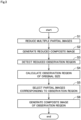
- Fig. 3 is a flowchart showing the procedure for generating the observation image 87 in accordance with the partial images 81.
- the computer 60 first reduces each of the partial images 81 (step S1). Accordingly, a plurality of reduced partial images 82 that are smaller in size than the partial images 81 of the original size are generated.
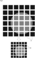
- Fig. 4 is a diagram showing the processing performed in step S 1. In the example shown in Fig. 4 , the 36 partial images 81 in Fig. 2 are reduced to generate 36 reduced partial images 82.
- the reduction ratio of the partial images 81 may be set to a fixed magnification by the computer 60.
- the computer 60 may determine the reduction ratio in accordance with the free space of the memory 62.
- the computer 60 stores the generated reduced partial images 82 in the memory 62. At this time, in order to save the storage capacity of the memory 62, the computer 60 may delete the partial images 81 of the original size from the memory 62 after the reduced partial images 82 have been generated.
- the computer 60 generates a reduced composite image 83 by combining the reduced partial images 82 (step S2).
- the reduced composite image 83 is an image of the entire imaging region that is smaller in size than the composite image obtained by combining the partial images 81 of the original size.
- Fig. 5 is a diagram showing the processing performed in step S2. In the example shown in Fig. 5 , the 36 reduced partial images 82 generated in Fig. 4 are combined into one reduced composite image 83.
- the computer 60 stores the generated reduced composite image 83 in the memory 62. At this time, in order to save the storage capacity of the memory 62, the computer 60 may delete the reduced partial images 82 from the memory 62 after the reduced composite image 83 has been generated.
- Fig. 6 is a diagram showing the processing performed in step S3.
- a rectangular region that includes the circular region corresponding to the well 91 is detected as the reduced observation region 84.
- the reduced observation region 84 is not the image data having a tone value for each pixel, but is information indicating a two-dimensional range of coordinates.
- the amount of data of the reduced observation region 84 is smaller than the amount of data of an image of the same size.
- the computer 60 stores the detected reduced observation region 84 in the memory 62. At this time, in order to save the storage capacity of the memory 62, the computer 60 may delete the reduced composite image 83 from the memory 62 after the reduced observation region 84 has been detected.
- Fig. 7 is a diagram showing the processing performed in step S4.
- the computer 60 calculates the observation region 85 of the original size by enlarging the reduced observation region 84 using a predetermined origin as the center.
- the enlargement ratio of the observation region is assumed to be a reciprocal of the reduction ratio of the partial image 81 in step S1.
- the reduced observation region 84 is enlarged to N times in step S4.
- N is assumed to be an integer greater than 1.
- Fig. 8 is a diagram showing the processing performed in step S5. As shown in Fig. 8 , the computer 60 selects partial images 81 that include at least part of the observation region 85 from among the partial images 81. Then, the computer 60 reads out the selected partial images 81 from the storage 63 into the memory 62.
- the computer 60 does not read those of the partial images 81 that do not correspond to the observation region 85 into the memory 62. That is, the computer 60 does not read the partial images 81 indicated by chain double-dashed lines in Fig. 8 into the memory 62. In the case where the memory 62 stores partial images 81 that do not correspond to the observation region 85, the computer 60 deletes these partial images 81 from the memory 62.
- the computer 60 generates an observation image 87 as a composite image of the observation region 85 by combining the partial images 81 selected in step S5 (step S6).
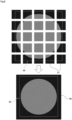
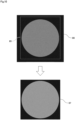
- Figs. 9 and 10 are diagrams showing the processing performed in step S6.
- the computer 60 first generates a composite image 86 by combining the selected partial images 81 as shown in Fig. 9 .
- the computer 60 cuts out the observation region 85 from the composite image 86 as shown in Fig. 10 . Accordingly, the image of the observation region 85 of the original size, i.e., the observation image 87, is generated.
- the computer 60 first generates the reduced composite image 83 by reducing the partial images 81 and then combining the reduced partial images. The computer 60 then detects the reduced observation region 84 corresponding to the observation region from the reduced composite image 83. Then, the computer 60 calculates the observation region 85 of the original size that is not reduced, from the reduced observation region 84. This reduces the storage capacity of the memory 62 required to detect the observation region 85 as compared to the case where the observation region 85 is detected from a composite image that is not reduced. Besides, since the size of data to be handled is reduced, the computer 60 is capable of detecting the observation region 85 at high speed.
- the computer 60 also generates the observation image 87 by combining only those of the partial images 81 that correspond to the observation region 85. This reduces the storage capacity of the memory 62 required to generate the composite image as compared to the case where a composite image of the entire imaging region is generated by using all of the partial images 81 of the imaging region. Besides, since the size of data to be handled is reduced, the computer 60 is capable of generating the observation image 87 at high speed.
- Fig. 11 is a flowchart showing the procedure for generating an observation image according to a first variation.
- the procedure shown in Fig. 11 differs from the procedure shown in Fig. 3 in that steps S4A to S7A are executed instead of steps S5 and S6 described above.
- Fig. 11 After the observation region 85 has been calculated in step S4, the computer 60 segments the observation region 85 into a plurality of segmented regions (step S4A).
- Fig. 12 is a diagram showing the processing performed in steps S4 to S4A.
- the observation region 85 is segmented into first to fourth segmented regions 851 to 854.
- the computer 60 stores the obtained first to fourth segmented regions 851 to 854 in the memory 62.
- Fig. 13 is a diagram showing the processing performed in step S5A. As shown in Fig. 13 , the computer 60 selects partial images 81 that include at least part of the first segmented region 851 from among the partial images 81. Then, the computer 60 reads out the selected partial images 81 from the storage 63 into the memory 62.
- the computer 60 does not read out those of the partial images 81 that do not correspond to the first segmented region 851 into the memory 62. That is, the computer 60 does not read the partial images 81 indicated by chain double-dashed lines in Fig. 13 into the memory 62. In the case where the memory 62 stores the partial images 81 that do not correspond to the first segmented region 851, the computer 60 deletes these partial images 81 from the memory 62.
- the computer 60 generates a composite image of the first segmented region 851, i.e., a first observation image, by combining the partial images 81 selected in step S5A (step S6A). Specifically, in the same manner as described in step S6, the selected partial images 81 are combined and then the first segmented region 851 is cut out from the obtained composite image.
- the computer 60 deletes the partial images 81 corresponding to the first segmented region 851 from the memory 62. Thereafter, the computer 60 determines whether the generation of the observation images for all of the segmented regions is completed (step S7A).
- step S7A the computer 60 executes the processing from steps S5A to S6A for the next segmented region. In this way, by repeating the processing from steps S5A to S6A, the observation images corresponding to the first, second, third, and fourth segmented regions 851, 852, 853, and 854 are generated in sequence.
- step S7A the computer 60 ends the processing for generating the observation images.
- the computer 60 segments the observation region 85 into the segmented regions 851 to 854. Then, the computer 60 combines the partial images 81 with different timing for each segmented region, which is smaller than the observation region 85. This further reduces the storage capacity of the memory 62 required at each time.
- the computer 60 deletes the partial images 81 corresponding to that segmented region from the memory 62.
- the partial images 81 that have been combined are sequentially deleted from the memory 62. This efficiently releases the storage area of the memory 62. Accordingly, it is possible to further reduce the storage capacity of the memory 62 required to generate the observation image.
- one observation region 85 is segmented into the four segmented regions 851 to 854.
- the number of segmented regions of the observation region 85 may be two, three, or five or more.
- Fig. 14 is a flowchart showing the procedure for generating the observation image 87 according to a second variation.
- the procedure shown in Fig. 14 differs from the procedure shown in Fig. 3 in that steps S3B to 4B are executed instead of steps S3 to S4 described above.
- Fig. 15 is a diagram showing the processing performed in step S3B.
- a circular reduced region of interest 88 that corresponds to the well 91 is detected from inside the reduced observation region 84.
- the reduced region of interest 88 is expressed by a straight line, an n-order polynomial, a circle, or an approximate combining them.
- the computer 60 stores the detected reduced region of interest 88 in the memory 62.
- the computer 60 calculates the observation region 85 and the region of interest of the original size that are not reduced, in accordance with the reduced observation region 84 and the reduced region of interest 88 (step S4B). As in the case of the reduced observation region 84, the computer 60 also calculates the region of interest of the original size by enlarging the reduced region of interest 88 using a predetermined origin as the center.
- the computer 60 detects not only the reduced observation region 84 but also the reduced region of interest 88 from the reduced composite image 83. Then, the region of interest of the original size is calculated by enlarging the reduced region of interest 88. This reduces the storage capacity of the memory 62 required to detect the region of interest as compared to the case where the region of interest is detected from the composite image of the original size. Besides, since the size of data to be handled is reduced, the computer 60 is capable of detecting the region of interest at high speed.
- the enlargement ratio of the region of interest in step S4B is assumed to be a reciprocal of the reduction ratio of the partial image 81 in step S1.
- the reduced region of interest 88 is enlarged to N times in step S4B.
- N is assumed to be an integer greater than 1.
- the region of interest may be determined to be a slightly larger region than the region obtained by enlarging the reduced region of interest 88 to N times, in consideration of the fact that errors may also be enlarged by the enlargement of the reduced region of interest 88. This reduces the possibility that an insufficient region of interest may be set in the observation image 87 of the original size.
- control of the operations of the imaging device 1 and the image processing for generating the observation image 87 are both executed by one computer 60.
- the control of the operations of the imaging device 1 and the image processing for generating the observation image 87 may be executed by different computers. That is, the image generation method according to the present invention may be executed by a different computer other than the computer of the imaging device for acquiring a plurality of partial images.
- the partial images 81 are captured under transmitted light.
- a plurality of partial images according to the present invention may be captured under other conditions such as under reflected light.
- each well 91 in the well plate 90 has a circular shape when viewed from above.
- the shape of each well 91 when viewed from above may be any shape other than a circular shape.
- each well 91 may have a rectangular shape with round corners when viewed from above.
- the container for storing the object to be observed is the well plate 90 including the wells 91.
- the container for storing the object to be observed may be any other item such as a schale (petri dish) having a single recessed portion.
Landscapes
- Engineering & Computer Science (AREA)
- Multimedia (AREA)
- Signal Processing (AREA)
- Physics & Mathematics (AREA)
- General Physics & Mathematics (AREA)
- Theoretical Computer Science (AREA)
- Computer Vision & Pattern Recognition (AREA)
- Microscoopes, Condenser (AREA)
- Image Processing (AREA)
- Editing Of Facsimile Originals (AREA)
- Studio Devices (AREA)
Abstract
Description
- This application claims the benefit of
Japanese Application No. 2023-023443, filed on February 17, 2023 - The present invention relates to a technique for generating an observation image by combining a plurality of images obtained by image capture.
- Imaging devices have conventionally been known that capture images of cells incubated in a specimen container such as a well plate at high resolutions. For example,
Japanese Patent Application Laid-Open No. 2017-161385 - This type of imaging device generates a single observation image by segmenting a specimen container into a plurality of regions, capturing an image of each region, and combining the captured images. However, if the images of the specimen container are to be captured at higher magnifications and higher resolutions, the size of data to be handled in image composition processing will increase. In that case, a computer that performs the image composition processing requires large-capacity memory. Besides, the increased size of data to be handled makes it difficult to perform the image composition processing at high speed.
- The present invention has been made in light of such circumstances, and it is an object of the present invention to provide a technique for reducing storage capacity required for memory in processing for generating an observation image by combining a plurality of images obtained by image capture.
- To solve the problem described above, a first aspect of the present application is an image generation method of generating an observation image from a plurality of partial images obtained by segmenting an imaging region including an object to be observed into a plurality of regions and capturing images of the plurality of regions, the observation image being a composite image of an observation region that is smaller than the imaging region. The image generation method causes a computer including memory to execute (a) generating a plurality of reduced partial images by reducing the plurality of partial images, (b) combining the plurality of reduced partial images into a reduced composite image, (c) detecting a reduced observation region that corresponds to the observation region from the reduced composite image, (d) calculating the observation region that is not reduced, in accordance with the reduced observation region, and (e) generating the observation image by combining, among the plurality of partial images, partial images that correspond to the observation region.
- A second aspect of the present application is the image generation method according to the first aspect, in which after the operation (d), among the plurality of partial images, partial images that do not correspond to the observation region are deleted from the memory.
- A third aspect of the present application is the image generation method according to the first or second aspect, in which the operation (e) includes (e-1) segmenting the observation region into a plurality of regions including a first segmented region and a second segmented region, (e-2) combining, among the plurality of partial images, partial images that correspond to the first segmented region into a composite image of the first segmented region, and (e-3) combining, among the plurality of partial images, partial images that correspond to the second segmented region into a composite image of the second segmented region. The operation (e-3) is executed after completion of the operation (e-2).
- A fourth aspect of the present application is the image generation method according to the third aspect, in which after the operation (e-2), the partial images that correspond to the first segmented region are deleted from the memory.
- A fifth aspect of the present application is the image generation method according to any one of the first to fourth aspects, in which the operation (c) further includes detecting a reduced region of interest that corresponds to a region of interest from the observation region, and the operation (d) further includes calculating the region of interest that is not reduced, in accordance with the reduced region of interest.
- A sixth aspect of the present application is the image generation method according to the fifth aspect, in which in the operation (a), the partial image is reduced to 1/N times, and in the operation (d), a region that is larger than a region obtained by enlarging the reduced region of interest to N times is determined as the region of interest.
- According to the first to sixth aspects, the observation region that is not reduced is calculated based on the reduced observation region detected from the reduced composite image. Accordingly, it is possible to reduce the size of data to be handled as compared to the case where an observation region is detected from a composite image that is not reduced. As a result, storage capacity required for the memory can be reduced.
- According to the first to sixth aspects, the observation image is generated by combining, among the partial images, only those that correspond to the observation region. Accordingly, it is possible to reduce the size of data to be handled as compared to the case where a composite image of the entire imaging region is obtained. As a result, the storage capacity required for the memory is reduced.
- In particular, according to the second aspect, the storage capacity required for the memory is further reduced by deleting partial images that do not correspond to the observation region from the memory.
- In particular, according to the third aspect, the composition of the partial images is performed with different timing for each segmented region. This further reduces the storage capacity required for the memory at each time.
- In particular, according to the fourth aspect, the storage area is released by deleting the partial images that have been combined from the memory. This further reduces the storage capacity required for the memory.
- In particular, according to the fifth aspect, the region of interest that is not reduced is calculated in accordance with the reduced region of interest detected from the reduced composite image. This reduces the storage capacity required for the memory as compared to the case where the region of interest is detected from a composite image that is not reduced.
- In particular, according to the sixth aspect, the region of interest is set relatively large in consideration of errors in the reduced region of interest. This reduces the possibility that an insufficient region of interest may be set.
- These and other objects, features, aspects and advantages of the present invention will become more apparent from the following detailed description of the present invention when taken in conjunction with the accompanying drawings.
-
-
Fig. 1 is a diagram showing an example of an imaging device; -
Fig. 2 is a diagram showing an example of a plurality of partial images; -
Fig. 3 is a flowchart showing the procedure for generating an observation image; -
Fig. 4 is a diagram showing processing performed in step S1; -
Fig. 5 is a diagram showing processing performed in step S2; -
Fig. 6 is a diagram showing processing performed in step S3; -
Fig. 7 is a diagram showing processing performed in step S4; -
Fig. 8 is a diagram showing processing performed in step S5; -
Fig. 9 is a diagram showing processing performed in step S6; -
Fig. 10 is a diagram showing the processing performed in step S6; -
Fig. 11 is a flowchart showing the procedure for generating an observation image according to a first variation; -
Fig. 12 is a diagram showing processing performed in steps S4 to S4A; -
Fig. 13 is a diagram showing processing performed in step S5A; -
Fig. 14 is a flowchart showing the procedure for generating an observation image according to a second variation; and -
Fig. 15 is a diagram showing processing performed in step S3B. - Hereinafter, a preferred embodiment of the present invention will be described with reference to the drawings.
-
Fig. 1 is a diagram showing an example of animaging device 1 that executes an image generation method according to the present invention. Theimaging device 1 is a device for capturing images of a specimen container at high resolutions, the specimencontainer storing cells 9 to be observed. The specimen container may, for example, awell plate 90. Thewell plate 90 is formed of a transparent resin that passes light. Thewell plate 90 includes a plurality ofwells 91. Eachwell 91 is a recessed portion that is recessed downward from the upper surface of thewell plate 90. For example, thewells 91 may have a circular shape when viewed from above. Thecells 9 are held together with a culture solution in eachwell 91. - An object to be observed may be a
single cell 9, or may be a cell cluster (spheroid) formed of a plurality ofcells 9. The object to be observed may also be the structure of a living organism or part of that structure. - As shown in
Fig. 1 , theimaging device 1 includes astage 10, aprojector 20, aprojector moving mechanism 30, acamera 40, acamera moving mechanism 50, and acomputer 60. - The
stage 10 is a placement base that holds thewell plate 90. The position of thestage 10 in theimaging device 1 is fixed at least during image capture. Thestage 10 has arectangular opening 11 in the center, the opening vertically penetrating the stage. Thestage 10 also has asupport face 12 extending along the outside shape of thewell plate 90 around theopening 11. Thewell plate 90 is fitted in theopening 11 and is supported in a horizontal position by thesupport face 12. Thus, the tops and bottoms of thewells 91 are exposed without being covered by thestage 10. - The
projector 20 is arranged above thewell plate 90 held on thestage 10. Theprojector 20 includes a light source such as LEDs. The light source in theprojector 20 emits light during image capture of thecells 9. Thus, downward illumination light (epi-illumination) is emitted from theprojector 20 toward thewell plate 90. - The
projector moving mechanism 30 is a mechanism for moving theprojector 20 in the horizontal direction along the upper surface of thewell plate 90 held on thestage 10. For example, theprojector moving mechanism 30 may be a mechanism for converting rotational motion of a motor into translatory motion via a ball screw. Theprojector moving mechanism 30 is capable of moving theprojector 20 relative to thewell plate 90 with fine pitches in the right-left direction and the depth direction inFig. 1 . The pitch of movement of theprojector 20 may be smaller than the size of onewell 91. - The
camera 40 is arranged below thewell plate 90 held on thestage 10. Thecamera 40 includes anoptical system 41 such as a lens and animage sensor 42 such as a CCD or a CMOS. During image capture of thecells 9, theprojector 20 emits downward illumination light toward a given portion of thewell plate 90, and thecamera 40 captures an image of that portion of thewell plate 90. In this way, thecamera 40 acquires an image of that portion of thewell plate 90. The image is digital data having a tone value for each pixel. Thecamera 40 outputs the acquired image to thecomputer 60. - The
camera moving mechanism 50 is a mechanism for moving thecamera 40 in the horizontal direction along the lower surface of thewell plate 90 held on thestage 10. For example, thecamera moving mechanism 50 may be a mechanism for converting rotational motion of a motor into translatory motion via a ball screw. Thecamera moving mechanism 50 is capable of moving thecamera 40 relative to thewell plate 90 with fine pitches in the right-left direction and the depth direction inFig. 1 . The pitch of movement of thecamera 40 is smaller than the size of onewell 91. - The
projector moving mechanism 30 and thecamera moving mechanism 50 described above are driven in synchronization with each other with the same pitch. Accordingly, theprojector 20 and thecamera 40 are always arranged in the same position when viewed from above. That is, theprojector 20 and thecamera 40 are moved by the same distance in the same direction. When thecamera 40 is arranged at a position below a certain portion of thewell plate 90, theprojector 20 is always arranged at a position above that portion of thewell plate 90. - The
computer 60 includes aprocessor 61 such as a CPU,memory 62 such as RAM, and astorage 63 such as a hard disk drive. Thestorage 63 stores a control program P1 for causing theimaging device 1 to execute imaging processing and an image processing program P2 for processing images obtained by image capture. - As shown in
Fig. 1 , thecomputer 60 is communicably connected to each of theprojector 20, theprojector moving mechanism 30, thecamera 40, and thecamera moving mechanism 50 described above. Thecomputer 60 controls operations of these components in accordance with the control program P1. This allows imaging processing by theimaging device 1 to proceed. - The
camera 40 segments an imaging region that includes one well 91 into a plurality of regions and captures images of these regions. That is, a region to be captured by a single image capture of thecamera 40 is smaller than the size of one well 91 in plan view. Theimaging device 1 repeats image capture by thecamera 40 and fine movements of theprojector 20 and thecamera 40 by theprojector moving mechanism 30 and thecamera moving mechanism 50. Accordingly, a plurality of images of fine regions of thewell plate 90 are obtained. Hereinafter, the images of fine regions of thewell plate 90 are referred to as "partial images 81." Thecamera 40 outputs a plurality ofpartial images 81 obtained by image capture to thecomputer 60. In this way, thecomputer 60 acquires a plurality ofpartial images 81. - The
computer 60 generates an observation composite image by processing thepartial images 81 input from thecamera 40 in accordance with the image processing program P2. Hereinafter, this observation composite image is referred to as the "observation image 87." The processing for generating theobservation image 87 will be described hereinafter. -
Fig. 2 is a diagram showing an example of a plurality ofpartial images 81. InFig. 2 , portions that correspond to the well 91 are indicated by gray, and portions other than the well 91 are indicated by black. In the example shown inFig. 2 , an imaging region that includes onewell 91 is segmented into and captured as 36partial images 81. Thepartial images 81 may include portions that overlap one another. Thecomputer 60 stores the obtainedpartial images 81 in thememory 62 or thestorage 63. -
Fig. 3 is a flowchart showing the procedure for generating theobservation image 87 in accordance with thepartial images 81. As shown inFig. 3 , thecomputer 60 first reduces each of the partial images 81 (step S1). Accordingly, a plurality of reducedpartial images 82 that are smaller in size than thepartial images 81 of the original size are generated.Fig. 4 is a diagram showing the processing performed instep S 1. In the example shown inFig. 4 , the 36partial images 81 inFig. 2 are reduced to generate 36 reducedpartial images 82. - The reduction ratio of the
partial images 81 may be set to a fixed magnification by thecomputer 60. Alternatively, thecomputer 60 may determine the reduction ratio in accordance with the free space of thememory 62. - The
computer 60 stores the generated reducedpartial images 82 in thememory 62. At this time, in order to save the storage capacity of thememory 62, thecomputer 60 may delete thepartial images 81 of the original size from thememory 62 after the reducedpartial images 82 have been generated. - Next, the
computer 60 generates a reducedcomposite image 83 by combining the reduced partial images 82 (step S2). The reducedcomposite image 83 is an image of the entire imaging region that is smaller in size than the composite image obtained by combining thepartial images 81 of the original size.Fig. 5 is a diagram showing the processing performed in step S2. In the example shown inFig. 5 , the 36 reducedpartial images 82 generated inFig. 4 are combined into one reducedcomposite image 83. - The
computer 60 stores the generated reducedcomposite image 83 in thememory 62. At this time, in order to save the storage capacity of thememory 62, thecomputer 60 may delete the reducedpartial images 82 from thememory 62 after the reducedcomposite image 83 has been generated. - Then, the
computer 60 detects a reducedobservation region 84 from the reducedcomposite image 83, the reduced observation region corresponding to an observation region smaller than the imaging region (step S3).Fig. 6 is a diagram showing the processing performed in step S3. In the example shown inFig. 6 , a rectangular region that includes the circular region corresponding to the well 91 is detected as the reducedobservation region 84. The reducedobservation region 84 is not the image data having a tone value for each pixel, but is information indicating a two-dimensional range of coordinates. Thus, the amount of data of the reducedobservation region 84 is smaller than the amount of data of an image of the same size. - The
computer 60 stores the detected reducedobservation region 84 in thememory 62. At this time, in order to save the storage capacity of thememory 62, thecomputer 60 may delete the reducedcomposite image 83 from thememory 62 after the reducedobservation region 84 has been detected. - Then, the
computer 60 calculates anobservation region 85 of the original size that is not reduced, in accordance with the reduced observation region 84 (step S4).Fig. 7 is a diagram showing the processing performed in step S4. As shown inFig. 7 , thecomputer 60 calculates theobservation region 85 of the original size by enlarging the reducedobservation region 84 using a predetermined origin as the center. The enlargement ratio of the observation region is assumed to be a reciprocal of the reduction ratio of thepartial image 81 in step S1. For example, in the case where thepartial image 81 is reduced to 1/N times in step S1, the reducedobservation region 84 is enlarged to N times in step S4. In this case, N is assumed to be an integer greater than 1. - Then, the
computer 60 selects thepartial images 81 that correspond to theobservation region 85 from among thepartial images 81 of the original size (step S5).Fig. 8 is a diagram showing the processing performed in step S5. As shown inFig. 8 , thecomputer 60 selectspartial images 81 that include at least part of theobservation region 85 from among thepartial images 81. Then, thecomputer 60 reads out the selectedpartial images 81 from thestorage 63 into thememory 62. - The
computer 60 does not read those of thepartial images 81 that do not correspond to theobservation region 85 into thememory 62. That is, thecomputer 60 does not read thepartial images 81 indicated by chain double-dashed lines inFig. 8 into thememory 62. In the case where thememory 62 storespartial images 81 that do not correspond to theobservation region 85, thecomputer 60 deletes thesepartial images 81 from thememory 62. - Thereafter, the
computer 60 generates anobservation image 87 as a composite image of theobservation region 85 by combining thepartial images 81 selected in step S5 (step S6).Figs. 9 and10 are diagrams showing the processing performed in step S6. Thecomputer 60 first generates acomposite image 86 by combining the selectedpartial images 81 as shown inFig. 9 . Thereafter, thecomputer 60 cuts out theobservation region 85 from thecomposite image 86 as shown inFig. 10 . Accordingly, the image of theobservation region 85 of the original size, i.e., theobservation image 87, is generated. - As described above, the
computer 60 first generates the reducedcomposite image 83 by reducing thepartial images 81 and then combining the reduced partial images. Thecomputer 60 then detects the reducedobservation region 84 corresponding to the observation region from the reducedcomposite image 83. Then, thecomputer 60 calculates theobservation region 85 of the original size that is not reduced, from the reducedobservation region 84. This reduces the storage capacity of thememory 62 required to detect theobservation region 85 as compared to the case where theobservation region 85 is detected from a composite image that is not reduced. Besides, since the size of data to be handled is reduced, thecomputer 60 is capable of detecting theobservation region 85 at high speed. - The
computer 60 also generates theobservation image 87 by combining only those of thepartial images 81 that correspond to theobservation region 85. This reduces the storage capacity of thememory 62 required to generate the composite image as compared to the case where a composite image of the entire imaging region is generated by using all of thepartial images 81 of the imaging region. Besides, since the size of data to be handled is reduced, thecomputer 60 is capable of generating theobservation image 87 at high speed. - While one embodiment of the present invention has been described thus far, the present invention is not intended to be limited to the aforementioned embodiment. Hereinafter, various variations will be described focusing on differences from the aforementioned embodiment.
-
Fig. 11 is a flowchart showing the procedure for generating an observation image according to a first variation. The procedure shown inFig. 11 differs from the procedure shown inFig. 3 in that steps S4A to S7A are executed instead of steps S5 and S6 described above. - In the example shown in
Fig. 11 , after theobservation region 85 has been calculated in step S4, thecomputer 60 segments theobservation region 85 into a plurality of segmented regions (step S4A).Fig. 12 is a diagram showing the processing performed in steps S4 to S4A. In the example shown inFig. 12 , theobservation region 85 is segmented into first to fourthsegmented regions 851 to 854. Thecomputer 60 stores the obtained first to fourthsegmented regions 851 to 854 in thememory 62. - Then, the
computer 60 selectspartial images 81 that correspond to the firstsegmented region 851 from among thepartial images 81 of the original size (step S5A).Fig. 13 is a diagram showing the processing performed in step S5A. As shown inFig. 13 , thecomputer 60 selectspartial images 81 that include at least part of the firstsegmented region 851 from among thepartial images 81. Then, thecomputer 60 reads out the selectedpartial images 81 from thestorage 63 into thememory 62. - The
computer 60 does not read out those of thepartial images 81 that do not correspond to the firstsegmented region 851 into thememory 62. That is, thecomputer 60 does not read thepartial images 81 indicated by chain double-dashed lines inFig. 13 into thememory 62. In the case where thememory 62 stores thepartial images 81 that do not correspond to the firstsegmented region 851, thecomputer 60 deletes thesepartial images 81 from thememory 62. - Then, the
computer 60 generates a composite image of the firstsegmented region 851, i.e., a first observation image, by combining thepartial images 81 selected in step S5A (step S6A). Specifically, in the same manner as described in step S6, the selectedpartial images 81 are combined and then the firstsegmented region 851 is cut out from the obtained composite image. - When the generation of the first observation image has completed, the
computer 60 deletes thepartial images 81 corresponding to the firstsegmented region 851 from thememory 62. Thereafter, thecomputer 60 determines whether the generation of the observation images for all of the segmented regions is completed (step S7A). - If the generation of the observation images for all of the segmented regions has not been completed yet (No in step S7A), the
computer 60 executes the processing from steps S5A to S6A for the next segmented region. In this way, by repeating the processing from steps S5A to S6A, the observation images corresponding to the first, second, third, and fourthsegmented regions - When the generation of the observation images for all of the segmented regions has completed (Yes in step S7A), the
computer 60 ends the processing for generating the observation images. - As described above, according to the first variation, the
computer 60 segments theobservation region 85 into thesegmented regions 851 to 854. Then, thecomputer 60 combines thepartial images 81 with different timing for each segmented region, which is smaller than theobservation region 85. This further reduces the storage capacity of thememory 62 required at each time. - In particular, according to the first variation, after the observation image corresponding to one segmented region is generated in step S6A, the
computer 60 deletes thepartial images 81 corresponding to that segmented region from thememory 62. In this way, thepartial images 81 that have been combined are sequentially deleted from thememory 62. This efficiently releases the storage area of thememory 62. Accordingly, it is possible to further reduce the storage capacity of thememory 62 required to generate the observation image. - In the example shown in
Fig. 12 , oneobservation region 85 is segmented into the foursegmented regions 851 to 854. However, the number of segmented regions of theobservation region 85 may be two, three, or five or more. -
Fig. 14 is a flowchart showing the procedure for generating theobservation image 87 according to a second variation. The procedure shown inFig. 14 differs from the procedure shown inFig. 3 in that steps S3B to 4B are executed instead of steps S3 to S4 described above. - In the example shown in
Fig. 14 , after the reducedcomposite image 83 has been generated, thecomputer 60 detects not only the reducedobservation region 84 but also a reduced region ofinterest 88 that corresponds to the well 91 (step S3B).Fig. 15 is a diagram showing the processing performed in step S3B. In the example shown inFig. 15 , a circular reduced region ofinterest 88 that corresponds to the well 91 is detected from inside the reducedobservation region 84. In two-dimensional coordinates, the reduced region ofinterest 88 is expressed by a straight line, an n-order polynomial, a circle, or an approximate combining them. Thecomputer 60 stores the detected reduced region ofinterest 88 in thememory 62. - Then, the
computer 60 calculates theobservation region 85 and the region of interest of the original size that are not reduced, in accordance with the reducedobservation region 84 and the reduced region of interest 88 (step S4B). As in the case of the reducedobservation region 84, thecomputer 60 also calculates the region of interest of the original size by enlarging the reduced region ofinterest 88 using a predetermined origin as the center. - As described above, according to the second variation, the
computer 60 detects not only the reducedobservation region 84 but also the reduced region ofinterest 88 from the reducedcomposite image 83. Then, the region of interest of the original size is calculated by enlarging the reduced region ofinterest 88. This reduces the storage capacity of thememory 62 required to detect the region of interest as compared to the case where the region of interest is detected from the composite image of the original size. Besides, since the size of data to be handled is reduced, thecomputer 60 is capable of detecting the region of interest at high speed. - The enlargement ratio of the region of interest in step S4B is assumed to be a reciprocal of the reduction ratio of the
partial image 81 in step S1. For example, in the case where thepartial images 81 are reduced to 1/N times in step S1, the reduced region ofinterest 88 is enlarged to N times in step S4B. In this case, N is assumed to be an integer greater than 1. It is, however, noted that the region of interest may be determined to be a slightly larger region than the region obtained by enlarging the reduced region ofinterest 88 to N times, in consideration of the fact that errors may also be enlarged by the enlargement of the reduced region ofinterest 88. This reduces the possibility that an insufficient region of interest may be set in theobservation image 87 of the original size. - In the aforementioned embodiment, the control of the operations of the
imaging device 1 and the image processing for generating theobservation image 87 are both executed by onecomputer 60. However, the control of the operations of theimaging device 1 and the image processing for generating theobservation image 87 may be executed by different computers. That is, the image generation method according to the present invention may be executed by a different computer other than the computer of the imaging device for acquiring a plurality of partial images. - In the aforementioned embodiment, the
partial images 81 are captured under transmitted light. However, a plurality of partial images according to the present invention may be captured under other conditions such as under reflected light. - In the aforementioned embodiment, each well 91 in the
well plate 90 has a circular shape when viewed from above. However, the shape of each well 91 when viewed from above may be any shape other than a circular shape. For example, each well 91 may have a rectangular shape with round corners when viewed from above. - In the aforementioned embodiment, the container for storing the object to be observed is the
well plate 90 including thewells 91. However, the container for storing the object to be observed may be any other item such as a schale (petri dish) having a single recessed portion. - Each element in the above-described embodiments and variations may be combined appropriately within a range that presents no contradictions.
Claims (6)
- An image generation method of generating an observation image (87) from a plurality of partial images (81) obtained by segmenting an imaging region including an object to be observed into a plurality of regions and capturing images of the plurality of regions, the observation image being a composite image of an observation region (85) that is smaller than the imaging region,
the image generation method causing a computer (60) including memory (62) to execute:(a) generating a plurality of reduced partial images (82) by reducing the plurality of partial images (81);(b) combining the plurality of reduced partial images (82) into a reduced composite image (83);(c) detecting a reduced observation region (84) that corresponds to the observation region (85) from the reduced composite image (83);(d) calculating the observation region (85) that is not reduced, in accordance with the reduced observation region (84); and(e) generating the observation image (87) by combining, among the plurality of partial images (81), partial images (81) that correspond to the observation region (85). - The image generation method according to claim 1, wherein
after the operation (d), among the plurality of partial images (81), partial images (81) that do not correspond to the observation region (85) are deleted from the memory (62). - The image generation method according to claim 1 or 2, whereinthe operation (e) includes:(e-1) segmenting the observation region (85) into a plurality of regions including a first segmented region (851) and a second segmented region (852);(e-2) combining, among the plurality of partial images (81), partial images (81) that correspond to the first segmented region (851) into a composite image of the first segmented region (851); and(e-3) combining, among the plurality of partial images (81), partial images (81) that correspond to the second segmented region (852) into a composite image of the second segmented region (852), andthe operation (e-3) is executed after completion of the operation (e-2).
- The image generation method according to claim 3, wherein
after the operation (e-2), the partial images (81) that correspond to the first segmented region (851) are deleted from the memory (62). - The image generation method according to claim 1 or 2, whereinthe operation (c) further includes detecting a reduced region of interest (88) that corresponds to a region of interest from the observation region (85), andthe operation (d) further includes calculating the region of interest that is not reduced, in accordance with the reduced region of interest (88).
- The image generation method according to claim 5, whereinin the operation (a), the partial image (81) is reduced to 1/N times, andin the operation (d), a region that is larger than a region obtained by enlarging the reduced region of interest (88) to N times is determined as the region of interest.
Applications Claiming Priority (1)
| Application Number | Priority Date | Filing Date | Title |
|---|---|---|---|
| JP2023023443A JP2024117376A (en) | 2023-02-17 | 2023-02-17 | Image Generation Method |
Publications (2)
| Publication Number | Publication Date |
|---|---|
| EP4418199A1 true EP4418199A1 (en) | 2024-08-21 |
| EP4418199B1 EP4418199B1 (en) | 2026-04-08 |
Family
ID=89722997
Family Applications (1)
| Application Number | Title | Priority Date | Filing Date |
|---|---|---|---|
| EP24153896.6A Active EP4418199B1 (en) | 2023-02-17 | 2024-01-25 | Image generation method |
Country Status (4)
| Country | Link |
|---|---|
| US (1) | US20240281922A1 (en) |
| EP (1) | EP4418199B1 (en) |
| JP (1) | JP2024117376A (en) |
| CN (1) | CN118524177A (en) |
Citations (4)
| Publication number | Priority date | Publication date | Assignee | Title |
|---|---|---|---|---|
| JP2017161385A (en) | 2016-03-10 | 2017-09-14 | 株式会社Screenホールディングス | Imaging arrangement determination method in imaging device, and imaging device |
| US10485505B2 (en) * | 2015-01-30 | 2019-11-26 | Canon Kabushiki Kaisha | Radiographing apparatus, control apparatus, stitch imaging system, control method |
| EP2929453B1 (en) * | 2012-12-06 | 2020-04-08 | Global Life Sciences Solutions USA LLC | Selection and display of biomarker expressions |
| US11010892B2 (en) * | 2016-10-07 | 2021-05-18 | Ventana Medical Systems, Inc. | Digital pathology system and associated workflow for providing visualized whole-slide image analysis |
-
2023
- 2023-02-17 JP JP2023023443A patent/JP2024117376A/en active Pending
-
2024
- 2024-01-25 EP EP24153896.6A patent/EP4418199B1/en active Active
- 2024-02-07 CN CN202410173675.XA patent/CN118524177A/en active Pending
- 2024-02-08 US US18/437,079 patent/US20240281922A1/en active Pending
Patent Citations (4)
| Publication number | Priority date | Publication date | Assignee | Title |
|---|---|---|---|---|
| EP2929453B1 (en) * | 2012-12-06 | 2020-04-08 | Global Life Sciences Solutions USA LLC | Selection and display of biomarker expressions |
| US10485505B2 (en) * | 2015-01-30 | 2019-11-26 | Canon Kabushiki Kaisha | Radiographing apparatus, control apparatus, stitch imaging system, control method |
| JP2017161385A (en) | 2016-03-10 | 2017-09-14 | 株式会社Screenホールディングス | Imaging arrangement determination method in imaging device, and imaging device |
| US11010892B2 (en) * | 2016-10-07 | 2021-05-18 | Ventana Medical Systems, Inc. | Digital pathology system and associated workflow for providing visualized whole-slide image analysis |
Also Published As
| Publication number | Publication date |
|---|---|
| JP2024117376A (en) | 2024-08-29 |
| CN118524177A (en) | 2024-08-20 |
| US20240281922A1 (en) | 2024-08-22 |
| EP4418199B1 (en) | 2026-04-08 |
Similar Documents
| Publication | Publication Date | Title |
|---|---|---|
| CN109417602B (en) | Image processing method, image processing apparatus, image capturing apparatus, and image capturing method | |
| US9088729B2 (en) | Imaging apparatus and method of controlling same | |
| US20130063585A1 (en) | Information processing apparatus, information processing method, and program | |
| JP5320329B2 (en) | SEM type defect observation apparatus and defect image acquisition method | |
| CN101079254A (en) | High resolution enabling apparatus and method | |
| CN1834582A (en) | Image processing method, three-dimensional position measuring method and image processing apparatus | |
| US11323630B2 (en) | Image processing method, image processor, and image capturing device | |
| CN111443475B (en) | Method and device for automatically positioning and scanning slide by objective lens | |
| CN110411946B (en) | Method for focusing camera image in digital slice scanner | |
| CN112964722A (en) | Visual detection method and detection system for ultra-large visual field distribution calculation | |
| JP6263589B1 (en) | Image processing method, image processing apparatus, and imaging apparatus | |
| US11094068B2 (en) | Image processing method and image processor | |
| EP4418199B1 (en) | Image generation method | |
| JP5371928B2 (en) | Defect inspection method and apparatus | |
| US11087510B2 (en) | Image processing method and image processor | |
| CN113472984B (en) | Image acquisition method, device, system, storage medium and equipment | |
| JP2018040569A (en) | Picked-up image arrangement determining method, image pick-up method, and image pick-up apparatus | |
| CN110958380B (en) | Image processing method and image processing apparatus | |
| US8482820B2 (en) | Image-capturing system | |
| JP2018019319A (en) | Image processing method, image processing apparatus, and imaging apparatus | |
| JP2016051168A (en) | Image acquisition apparatus and control method thereof | |
| EP2947487A1 (en) | Image acquisition device and focus method for image acquisition device | |
| US11233932B2 (en) | Focusing position detection method, focusing position detector, recording medium, and focusing position detection program | |
| JP2023535038A (en) | Whole slide imaging method for microscopy | |
| EP4125065B1 (en) | Image processing method and classification model construction method |
Legal Events
| Date | Code | Title | Description |
|---|---|---|---|
| PUAI | Public reference made under article 153(3) epc to a published international application that has entered the european phase |
Free format text: ORIGINAL CODE: 0009012 |
|
| STAA | Information on the status of an ep patent application or granted ep patent |
Free format text: STATUS: THE APPLICATION HAS BEEN PUBLISHED |
|
| AK | Designated contracting states |
Kind code of ref document: A1 Designated state(s): AL AT BE BG CH CY CZ DE DK EE ES FI FR GB GR HR HU IE IS IT LI LT LU LV MC ME MK MT NL NO PL PT RO RS SE SI SK SM TR |
|
| STAA | Information on the status of an ep patent application or granted ep patent |
Free format text: STATUS: REQUEST FOR EXAMINATION WAS MADE |
|
| 17P | Request for examination filed |
Effective date: 20250219 |
|
| GRAP | Despatch of communication of intention to grant a patent |
Free format text: ORIGINAL CODE: EPIDOSNIGR1 |
|
| STAA | Information on the status of an ep patent application or granted ep patent |
Free format text: STATUS: GRANT OF PATENT IS INTENDED |
|
| RIC1 | Information provided on ipc code assigned before grant |
Ipc: G06T 3/4038 20240101AFI20251017BHEP Ipc: H04N 23/698 20230101ALI20251017BHEP |
|
| INTG | Intention to grant announced |
Effective date: 20251104 |
|
| GRAJ | Information related to disapproval of communication of intention to grant by the applicant or resumption of examination proceedings by the epo deleted |
Free format text: ORIGINAL CODE: EPIDOSDIGR1 |
|
| STAA | Information on the status of an ep patent application or granted ep patent |
Free format text: STATUS: REQUEST FOR EXAMINATION WAS MADE |
|
| P01 | Opt-out of the competence of the unified patent court (upc) registered |
Free format text: CASE NUMBER: UPC_APP_0016150_4418199/2025 Effective date: 20251208 |
|
| GRAP | Despatch of communication of intention to grant a patent |
Free format text: ORIGINAL CODE: EPIDOSNIGR1 |
|
| STAA | Information on the status of an ep patent application or granted ep patent |
Free format text: STATUS: GRANT OF PATENT IS INTENDED |
|
| INTC | Intention to grant announced (deleted) | ||
| INTG | Intention to grant announced |
Effective date: 20260126 |
|
| GRAS | Grant fee paid |
Free format text: ORIGINAL CODE: EPIDOSNIGR3 |
|
| GRAA | (expected) grant |
Free format text: ORIGINAL CODE: 0009210 |
|
| STAA | Information on the status of an ep patent application or granted ep patent |
Free format text: STATUS: THE PATENT HAS BEEN GRANTED |
|
| AK | Designated contracting states |
Kind code of ref document: B1 Designated state(s): AL AT BE BG CH CY CZ DE DK EE ES FI FR GB GR HR HU IE IS IT LI LT LU LV MC ME MK MT NL NO PL PT RO RS SE SI SK SM TR |
|
| REG | Reference to a national code |
Ref country code: CH Ref legal event code: F10 Free format text: ST27 STATUS EVENT CODE: U-0-0-F10-F00 (AS PROVIDED BY THE NATIONAL OFFICE) Effective date: 20260408 Ref country code: GB Ref legal event code: FG4D |
|
| REG | Reference to a national code |
Ref country code: DE Ref legal event code: R096 Ref document number: 602024003680 Country of ref document: DE |