EP4418020A1 - Tsunami learning device, tsunami learning method, tsunami prediction device, and tsunami prediction method - Google Patents
Tsunami learning device, tsunami learning method, tsunami prediction device, and tsunami prediction method Download PDFInfo
- Publication number
- EP4418020A1 EP4418020A1 EP21966423.2A EP21966423A EP4418020A1 EP 4418020 A1 EP4418020 A1 EP 4418020A1 EP 21966423 A EP21966423 A EP 21966423A EP 4418020 A1 EP4418020 A1 EP 4418020A1
- Authority
- EP
- European Patent Office
- Prior art keywords
- tsunami
- cnn
- dimension
- feature extracting
- size
- Prior art date
- Legal status (The legal status is an assumption and is not a legal conclusion. Google has not performed a legal analysis and makes no representation as to the accuracy of the status listed.)
- Granted
Links
Images




Classifications
-
- G—PHYSICS
- G06—COMPUTING OR CALCULATING; COUNTING
- G06N—COMPUTING ARRANGEMENTS BASED ON SPECIFIC COMPUTATIONAL MODELS
- G06N3/00—Computing arrangements based on biological models
- G06N3/02—Neural networks
- G06N3/08—Learning methods
-
- G—PHYSICS
- G01—MEASURING; TESTING
- G01W—METEOROLOGY
- G01W1/00—Meteorology
- G01W1/10—Devices for predicting weather conditions
-
- G—PHYSICS
- G01—MEASURING; TESTING
- G01S—RADIO DIRECTION-FINDING; RADIO NAVIGATION; DETERMINING DISTANCE OR VELOCITY BY USE OF RADIO WAVES; LOCATING OR PRESENCE-DETECTING BY USE OF THE REFLECTION OR RERADIATION OF RADIO WAVES; ANALOGOUS ARRANGEMENTS USING OTHER WAVES
- G01S13/00—Systems using the reflection or reradiation of radio waves, e.g. radar systems; Analogous systems using reflection or reradiation of waves whose nature or wavelength is irrelevant or unspecified
- G01S13/88—Radar or analogous systems specially adapted for specific applications
- G01S13/95—Radar or analogous systems specially adapted for specific applications for meteorological use
-
- G—PHYSICS
- G01—MEASURING; TESTING
- G01S—RADIO DIRECTION-FINDING; RADIO NAVIGATION; DETERMINING DISTANCE OR VELOCITY BY USE OF RADIO WAVES; LOCATING OR PRESENCE-DETECTING BY USE OF THE REFLECTION OR RERADIATION OF RADIO WAVES; ANALOGOUS ARRANGEMENTS USING OTHER WAVES
- G01S7/00—Details of systems according to groups G01S13/00, G01S15/00, G01S17/00
- G01S7/02—Details of systems according to groups G01S13/00, G01S15/00, G01S17/00 of systems according to group G01S13/00
- G01S7/41—Details of systems according to groups G01S13/00, G01S15/00, G01S17/00 of systems according to group G01S13/00 using analysis of echo signal for target characterisation; Target signature; Target cross-section
- G01S7/417—Details of systems according to groups G01S13/00, G01S15/00, G01S17/00 of systems according to group G01S13/00 using analysis of echo signal for target characterisation; Target signature; Target cross-section involving the use of neural networks
-
- G—PHYSICS
- G01—MEASURING; TESTING
- G01V—GEOPHYSICS; GRAVITATIONAL MEASUREMENTS; DETECTING MASSES OR OBJECTS; TAGS
- G01V1/00—Seismology; Seismic or acoustic prospecting or detecting
- G01V1/38—Seismology; Seismic or acoustic prospecting or detecting specially adapted for water-covered areas
- G01V1/3808—Seismic data acquisition, e.g. survey design
-
- G—PHYSICS
- G06—COMPUTING OR CALCULATING; COUNTING
- G06N—COMPUTING ARRANGEMENTS BASED ON SPECIFIC COMPUTATIONAL MODELS
- G06N3/00—Computing arrangements based on biological models
- G06N3/02—Neural networks
- G06N3/04—Architecture, e.g. interconnection topology
- G06N3/0464—Convolutional networks [CNN, ConvNet]
-
- G—PHYSICS
- G06—COMPUTING OR CALCULATING; COUNTING
- G06N—COMPUTING ARRANGEMENTS BASED ON SPECIFIC COMPUTATIONAL MODELS
- G06N3/00—Computing arrangements based on biological models
- G06N3/02—Neural networks
- G06N3/08—Learning methods
- G06N3/09—Supervised learning
-
- G—PHYSICS
- G01—MEASURING; TESTING
- G01V—GEOPHYSICS; GRAVITATIONAL MEASUREMENTS; DETECTING MASSES OR OBJECTS; TAGS
- G01V1/00—Seismology; Seismic or acoustic prospecting or detecting
- G01V1/01—Measuring or predicting earthquakes
-
- Y—GENERAL TAGGING OF NEW TECHNOLOGICAL DEVELOPMENTS; GENERAL TAGGING OF CROSS-SECTIONAL TECHNOLOGIES SPANNING OVER SEVERAL SECTIONS OF THE IPC; TECHNICAL SUBJECTS COVERED BY FORMER USPC CROSS-REFERENCE ART COLLECTIONS [XRACs] AND DIGESTS
- Y02—TECHNOLOGIES OR APPLICATIONS FOR MITIGATION OR ADAPTATION AGAINST CLIMATE CHANGE
- Y02A—TECHNOLOGIES FOR ADAPTATION TO CLIMATE CHANGE
- Y02A90/00—Technologies having an indirect contribution to adaptation to climate change
- Y02A90/10—Information and communication technologies [ICT] supporting adaptation to climate change, e.g. for weather forecasting or climate simulation
Definitions
- the technique of the present disclosure relates to a tsunami learning device, a tsunami learning method, a tsunami prediction device, and a tsunami prediction method.
- a technique of predicting a tsunami height and a tsunami arrival time using observation data of a marine radar is known.
- a tsunami height and tsunami arrival time prediction system implements prediction by adopting convolutional neural networks (CNN) for a learning model.
- CNN convolutional neural networks
- Patent Literature 1 JP 2020-173160 A
- CNN is often used in a field of image recognition.
- RGB data is set in a channel direction
- n ⁇ n (n is a natural number of 2 or more) is set as the size of a convolution filter.
- CNN used for tsunami prediction there is a degree of freedom in design, such as which physical quantity is set in a channel direction or what size a convolution filter is set to.
- CNN used for the system described in Patent Literature 1 sets time-series data in a channel direction. It is conceivable to set the size of a convolution filter in this system to n ⁇ n similarly to a case of using CNN for image recognition.
- a tsunami height and tsunami arrival time prediction system in which time-series data is set in a channel direction and the size of a convolution filter is set to n ⁇ n is referred to as "conventional technique”.
- an object of the technique of the present disclosure is to provide a tsunami prediction device having higher prediction accuracy than that of the conventional technique.
- a tsunami learning device includes: an input unit to acquire a training data set including observation data of a marine radar; and a CNN unit including CNN, to perform CNN processing on the training data set.
- the observation data is input to the CNN in such a manner that a channel direction of an input layer is an orientation direction of the observation data.
- the CNN includes a distance dimension feature extracting unit, a temporal dimension feature extracting unit, and a time-series prediction unit.
- the distance dimension feature extracting unit has one or more distance dimension convolution layers, and each of the distance dimension convolution layers has a filter having a size of 1 in a temporal dimension and a size of a natural number in a distance dimension.
- the temporal dimension feature extracting unit has one or more temporal dimension convolution layers, and each of the temporal dimension convolution layers has a convolutional filter having a size of a natural number in the temporal dimension and a size of a natural number in a distance dimension.
- the training data set is a set of simulated tsunami observation data and tsunami waveform data at a prediction point.
- the tsunami prediction device according to the technique of the present disclosure has an effect that prediction accuracy is higher than that of the conventional technique.
- a tsunami prediction device 100 is a device that predicts inundation on land due to tsunami or a wave height of tsunami on sea.
- the tsunami prediction device 100 is a device using artificial intelligence (AI), and can be considered with separating into a learning phase and an AI utilization phase. Only in a case where it is necessary to clarify the learning phase and the AI utilization phase, the present device in the learning phase is distinguished by referring to as a tsunami learning device. In addition, the tsunami prediction device 100 in the AI utilization phase only needs to include a CNN model learned by the technique of the present disclosure, and does not need to include a learning function itself.
- AI artificial intelligence
- FIG. 1 is a block diagram illustrating functional blocks of a tsunami prediction device 100 according to a first embodiment.
- the tsunami prediction device 100 includes an input unit 10, a preprocessing unit 20, a CNN unit 30, and an output unit 40.
- the tsunami prediction device 100 uses observation data from a marine radar as input information.
- the observation data is assumed to be a flow rate, but may be a physical quantity such as a wave height or a water pressure.
- the input unit 10 of the tsunami prediction device 100 receives the observation data from the marine radar. Details of a region observed by the marine radar will be apparent from description of FIG. 4 described later.
- input information used in the learning phase may be different from that used in the AI utilization phase.
- the tsunami learning device in the learning phase may perform a tsunami simulation assuming a large number of scenarios by utilizing a supercomputer in advance, generate tsunami simulation data, and use simulated tsunami observation data as input information.
- the actual tsunami observation data may be used as the input information. That is, the "observation data from the marine radar" can include simulated observation data or actual observation data.
- the tsunami prediction device 100 may use actual observation data obtained in real time at the time of occurrence of an earthquake or the like as the input information.
- the preprocessing unit 20 of the tsunami prediction device 100 performs preprocessing on the input observation data. More specifically, the preprocessing unit 20 performs processing of converting the observation data from the marine radar input to the input unit 10 into a format that can be handled by the CNN unit 30. Details of the preprocessing will be apparent from the following description.
- the CNN unit 30 of the tsunami prediction device 100 includes CNN as a learning model.
- the CNN unit 30 performs CNN processing on the preprocessed observation data.
- the CNN includes a distance dimension feature extracting unit, a temporal dimension feature extracting unit, and a time-series prediction unit.
- the CNN learns a relationship between the simulated tsunami observation data and a tsunami waveform at a prediction point.
- a set of the simulated tsunami observation data and the tsunami waveform data at the prediction point used for learning is referred to as a training data set. Details of the CNN will be apparent from the following description.
- the output unit 40 of the tsunami prediction device 100 outputs a prediction result obtained by the CNN processing. More specifically, the output unit 40 outputs a predicted waveform of tsunami at the prediction point.
- the prediction point is not limited to one point, and prediction at a plurality of points can be performed simultaneously.
- FIG. 2 is a flowchart illustrating processing steps of the tsunami prediction device 100 according to the first embodiment.
- the processing steps of the tsunami prediction device 100 include input processing ST10 performed by the input unit 10, preprocessing ST20 performed by the preprocessing unit 20, CNN processing ST30 performed by the CNN unit 30, and output processing ST40 performed by the output unit 40.
- FIG. 3 is a hardware configuration diagram of the tsunami prediction device 100 according to the first embodiment.
- the tsunami prediction device 100 may include an input interface 50, a processor 60, a memory 70, and an output interface 80.
- the tsunami prediction device 100 includes a processing circuit for performing tsunami prediction by inputting, preprocessing, CNN processing, and outputting observation data.
- the processing circuit may be dedicated hardware or the processor 60 that executes a program stored in the memory 70.
- the processor 60 is also referred to as a CPU, a central processing device, a processing device, an arithmetic device, a microprocessor, a microcomputer, or a DSP.
- each of functions of the input unit 10, the preprocessing unit 20, the CNN unit 30, and the output unit 40 may be implemented by the processing circuit, or the functions of the units may be collectively implemented by the processing circuit.
- the functions of the input unit 10, the preprocessing unit 20, the CNN unit 30, and the output unit 40 are implemented by software, firmware, or a combination of software and firmware.
- the software and the firmware are each described as a program and stored in the memory 70.
- the processing circuit implements the functions of the units. That is, the tsunami prediction device 100 includes the memory 70 for storing programs that cause the input processing ST10 performed by the input unit 10, the preprocessing ST20 performed by the preprocessing unit 20, the CNN processing ST30 performed by the CNN unit 30, and the output processing ST40 performed by the output unit 40 to be executed as a result when the programs are executed by the processing circuit.
- the memory 70 may be a nonvolatile or volatile semiconductor memory such as a RAM, a ROM, a flash memory, an EPROM, or an EEPROM.
- the memory 70 may be a magnetic disk, a flexible disk, an optical disk, a compact disk, a mini disk, or a DVD.
- the memory 70 may be an HDD or an SSD.
- some of the functions of the input unit 10, the preprocessing unit 20, the CNN unit 30, and the output unit 40 may be configured by dedicated hardware, and some of the functions may be configured by software or firmware.
- the processing circuitry can implement the functions of the tsunami prediction device 100 by hardware, software, firmware, or a combination thereof.
- FIG. 4 is a schematic diagram illustrating arrangement of observation points of observation data used as input to the tsunami prediction device 100 according to the first embodiment.
- the observation data is actually or simulatively acquired by a marine radar.
- the observation points are set at equal intervals in a direction away from a transmission antenna on a plurality of lines of sight spreading in a fan shape around a transmission and reception antenna of the marine radar.
- the observation data used by the tsunami prediction device 100 has a dimension and a spread as a plane when an observation region of the marine radar is viewed from the sky.
- the direction away from the transmission antenna is referred to as a "distance dimension”
- a rotation direction around the marine radar is referred to as an "orientation direction”.
- FIG. 5 is a schematic diagram illustrating a structure of an input layer of CNN in the CNN unit 30 according to the first embodiment.
- a left side of an arrow (a source of the arrow) in FIG. 5 illustrates the structure of the input layer of the CNN in which a time-series direction is a channel direction (conventional technique).
- a right side of the arrow (a tip of the arrow) in FIG. 5 illustrates the structure of the input layer of the CNN in the CNN unit 30 according to the first embodiment.
- observation data is input to the CNN of the CNN unit 30 according to the first embodiment in such a manner that the channel direction is the orientation direction of the observation data in the input layer.
- FIG. 6 illustrates input and output of the distance dimension feature extracting unit of the CNN in the CNN unit 30 according to the first embodiment.
- a convolution layer in CNN performs an operation called two-dimensional convolution.
- Typical examples of the convolution operation in image processing include a blurring operation using a Gaussian filter and contour extraction using a Laplacian filter.
- a two-dimensional convolution filter such as n ⁇ n is often used in the convolution layer in the CNN.
- the distance dimension feature extracting unit of the CNN in the CNN unit 30 according to the first embodiment has one or more distance dimension convolution layers.
- the distance dimension convolution layer has a convolution filter having a size of 1 in a temporal dimension and a size of a natural number in a distance dimension. By adopting such a size of the convolution filter, a convolution operation is performed only on a flow rate distribution in the distance dimension, and as a result, a feature in the distance dimension of the flow rate distribution is extracted independently of a feature in the temporal dimension of the flow rate distribution.
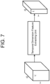
- FIG. 7 is a schematic diagram illustrating the temporal dimension feature extracting unit of the CNN in the CNN unit 30 according to the first embodiment. More specifically, FIG. 7 illustrates input and output of the temporal dimension feature extracting unit of the CNN in the CNN unit 30 according to the first embodiment.
- the temporal dimension feature extracting unit of the CNN in the CNN unit 30 according to the first embodiment has one or more temporal dimension convolution layers.
- the temporal dimension convolution layer has a convolution filter having a size of a natural number in a temporal dimension and a size of a natural number in a distance dimension. By adopting such a size of the convolution filter, a convolution operation is performed on a feature in the temporal dimension, and as a result, a feature of a flow rate distribution in the temporal dimension is extracted. Note that a plurality of the convolution layers of the temporal dimension feature extracting unit can be connected.
- the feature extraction in the temporal dimension may be implemented not only by the convolution operation but also by RNN, a transformer, or the like.
- FIG. 8 is a schematic diagram illustrating a processing process of the CNN in the CNN unit 30 according to the first embodiment, that is, the CNN processing ST30.
- output of the time-series prediction unit of the CNN in the CNN unit 30 is a tsunami waveform including a current time at a prediction point.
- auxiliary information such as earthquake seismic source information may be used in the CNN processing process in the CNN unit 30.
- the seismic source information may be added to a training data set which is teacher data, or may be added to an intermediate product of the CNN as illustrated in FIG. 8 .
- auxiliary information include, in addition to the seismic source information, a water pressure acquired by a submarine cable and a tide level change in a GPS wave meter. Addition of the auxiliary information makes it possible to further characterize a pattern of tsunami to be learned, which is expected to improve prediction accuracy of tsunami.
- FIG. 9 is a schematic diagram in a case where output of the tsunami prediction device 100 according to the first embodiment is set to an inundation depth on land.
- the vertical axis represents an inundation depth [m]
- the horizontal axis represents an elapsed time [min].
- FIG. 9 When FIG. 9 is viewed as a graph in the learning phase, a true value in the graph represents a plot of teacher data used for learning.
- the teacher data is generated by simulation using a supercomputer in many cases, but may be an actual measured value when the actual measured value is available.
- the tsunami prediction device 100 can predict "a wave height or an inundation depth of y [m] after an elapse of x minutes" from a result of time-series regression.
- the output of the tsunami prediction device 100 may perform prediction in consideration of a probability distribution. That is, the tsunami prediction device 100 according to the technique of the present disclosure may output a prediction result of "a wave height or an inundation depth of y ⁇ ⁇ y [m] after an elapse of x minutes".
- FIG. 9 when FIG. 9 is viewed as a graph in the AI utilization phase, a true value in the graph represents a plot of an actual measured value.
- FIG. 10 is a schematic diagram illustrating the learning phase of the tsunami prediction device 100 according to the first embodiment, that is, an example of creating a training data set in the tsunami learning device.
- FIG. 10 illustrates a contrivance of bringing a simulation waveform close to an actual waveform by adding time-series observation data in normal times to time-series data of simulation representing a wave height at a certain observation point. This is because, in general, waveform data that can be generated by simulation is flow rate component data of tsunami itself, and it is difficult to model a component such as fluctuation or noise derived from a matter other than the tsunami.
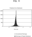
- FIG. 11 is a graph illustrating a prediction error distribution of the learned tsunami prediction device 100 according to the first embodiment in comparison with that of the conventional technique.
- the number of pieces of simulation data of tsunami used in an experiment of the prediction performance comparison illustrated in FIG. 11 was 1519, 1209 pieces of which were used as a training data set, and the remaining 310 pieces were used as a verification data set for performance comparison.
- comparison of an error distribution for a maximum inundation depth was performed.
- a CPU and a GPU used for the prediction device for comparison were the same as those of the tsunami prediction device 100 according to the technique of the present disclosure.
- a convolution filter of CNN according to the prediction device for comparison had a size of 3 ⁇ 3, and data at past ten time points was used as input.
- a convolution filter of the feature extracting unit had a size of 1 ⁇ 3
- a convolution filter of the temporal dimension feature extracting unit had a size of 2 ⁇ 1
- data at past eight time points was used as input.
- the tsunami prediction device 100 Since the tsunami prediction device 100 according to the first embodiment has the above configuration, a feature is extracted while a time axis and a spatial axis are independent of each other in the convolution layer in the CNN. By this function, the tsunami prediction device 100 according to the technique of the present disclosure has a smaller predicted average absolute error and higher prediction accuracy than that of the conventional technique.
- the tsunami prediction device 100 can be used in actual tsunami disaster prevention, and has industrial applicability.
Landscapes
- Engineering & Computer Science (AREA)
- Physics & Mathematics (AREA)
- Life Sciences & Earth Sciences (AREA)
- Theoretical Computer Science (AREA)
- General Physics & Mathematics (AREA)
- Evolutionary Computation (AREA)
- Artificial Intelligence (AREA)
- Remote Sensing (AREA)
- Molecular Biology (AREA)
- General Health & Medical Sciences (AREA)
- Biomedical Technology (AREA)
- Biophysics (AREA)
- Computational Linguistics (AREA)
- Data Mining & Analysis (AREA)
- Health & Medical Sciences (AREA)
- Software Systems (AREA)
- Mathematical Physics (AREA)
- Computing Systems (AREA)
- General Engineering & Computer Science (AREA)
- Radar, Positioning & Navigation (AREA)
- Environmental & Geological Engineering (AREA)
- Computer Networks & Wireless Communication (AREA)
- Oceanography (AREA)
- Acoustics & Sound (AREA)
- Geology (AREA)
- General Life Sciences & Earth Sciences (AREA)
- Geophysics (AREA)
- Atmospheric Sciences (AREA)
- Biodiversity & Conservation Biology (AREA)
- Ecology (AREA)
- Environmental Sciences (AREA)
- Electromagnetism (AREA)
- Geophysics And Detection Of Objects (AREA)
- Radar Systems Or Details Thereof (AREA)
- Management, Administration, Business Operations System, And Electronic Commerce (AREA)
Abstract
Description
- The technique of the present disclosure relates to a tsunami learning device, a tsunami learning method, a tsunami prediction device, and a tsunami prediction method.
- A technique of predicting a tsunami height and a tsunami arrival time using observation data of a marine radar is known.
- For example, a tsunami height and tsunami arrival time prediction system according to Patent Literature 1 implements prediction by adopting convolutional neural networks (CNN) for a learning model.
- Patent Literature 1:
JP 2020-173160 A - CNN is often used in a field of image recognition. When CNN is used for image recognition, generally, RGB data is set in a channel direction, and n × n (n is a natural number of 2 or more) is set as the size of a convolution filter. Meanwhile, when CNN is used for tsunami prediction, there is a degree of freedom in design, such as which physical quantity is set in a channel direction or what size a convolution filter is set to. For example, CNN used for the system described in Patent Literature 1 sets time-series data in a channel direction. It is conceivable to set the size of a convolution filter in this system to n × n similarly to a case of using CNN for image recognition. Hereinafter, a tsunami height and tsunami arrival time prediction system in which time-series data is set in a channel direction and the size of a convolution filter is set to n × n is referred to as "conventional technique".
- However, as described above, in consideration of the degree of freedom in design in a case where CNN is used for tsunami prediction, there is a possibility that there is CNN setting with higher accuracy in tsunami prediction than in the conventional technique.
- Therefore, an object of the technique of the present disclosure is to provide a tsunami prediction device having higher prediction accuracy than that of the conventional technique.
- A tsunami learning device according to the technique of the present disclosure includes: an input unit to acquire a training data set including observation data of a marine radar; and a CNN unit including CNN, to perform CNN processing on the training data set. The observation data is input to the CNN in such a manner that a channel direction of an input layer is an orientation direction of the observation data. The CNN includes a distance dimension feature extracting unit, a temporal dimension feature extracting unit, and a time-series prediction unit. The distance dimension feature extracting unit has one or more distance dimension convolution layers, and each of the distance dimension convolution layers has a filter having a size of 1 in a temporal dimension and a size of a natural number in a distance dimension. The temporal dimension feature extracting unit has one or more temporal dimension convolution layers, and each of the temporal dimension convolution layers has a convolutional filter having a size of a natural number in the temporal dimension and a size of a natural number in a distance dimension. The training data set is a set of simulated tsunami observation data and tsunami waveform data at a prediction point.
- With the above-described configuration, the tsunami prediction device according to the technique of the present disclosure has an effect that prediction accuracy is higher than that of the conventional technique.
-
-
FIG. 1 is a block diagram illustrating functional blocks of a tsunami prediction device according to the technique of the present disclosure. -
FIG. 2 is a flowchart illustrating processing steps of the tsunami prediction device according to the technique of the present disclosure. -
FIG. 3 is a hardware configuration diagram of the tsunami prediction device according to the technique of the present disclosure. -
FIG. 4 is a schematic diagram illustrating arrangement of observation points of observation data used as input to the tsunami prediction device according to the technique of the present disclosure. -
FIG. 5 is a schematic diagram illustrating a structure of input data to a CNN unit according to the technique of the present disclosure. -
FIG. 6 is a schematic diagram illustrating input and output of a distance dimension feature extracting unit of CNN according to the technique of the present disclosure. -
FIG. 7 is a schematic diagram illustrating a temporal dimension feature extracting unit of the CNN according to the technique of the present disclosure. -
FIG. 8 is a schematic diagram illustrating a processing process of the CNN according to the technique of the present disclosure. -
FIG. 9 is a schematic diagram illustrating output of the tsunami prediction device according to the technique of the present disclosure. -
FIG. 10 is a schematic diagram illustrating an example of creating training data according to the technique of the present disclosure. -
FIG. 11 is a graph illustrating an effect of the learned tsunami prediction device according to the technique of the present disclosure. - A
tsunami prediction device 100 according to the technique of the present disclosure is a device that predicts inundation on land due to tsunami or a wave height of tsunami on sea. - The
tsunami prediction device 100 according to the technique of the present disclosure is a device using artificial intelligence (AI), and can be considered with separating into a learning phase and an AI utilization phase. Only in a case where it is necessary to clarify the learning phase and the AI utilization phase, the present device in the learning phase is distinguished by referring to as a tsunami learning device. In addition, thetsunami prediction device 100 in the AI utilization phase only needs to include a CNN model learned by the technique of the present disclosure, and does not need to include a learning function itself. -
FIG. 1 is a block diagram illustrating functional blocks of atsunami prediction device 100 according to a first embodiment. As illustrated inFIG. 1 , thetsunami prediction device 100 includes aninput unit 10, a preprocessingunit 20, a CNNunit 30, and anoutput unit 40. - The
tsunami prediction device 100 according to the first embodiment uses observation data from a marine radar as input information. Specifically, the observation data is assumed to be a flow rate, but may be a physical quantity such as a wave height or a water pressure. Theinput unit 10 of thetsunami prediction device 100 receives the observation data from the marine radar. Details of a region observed by the marine radar will be apparent from description ofFIG. 4 described later. - In the
tsunami prediction device 100 according to the technique of the present disclosure, input information used in the learning phase may be different from that used in the AI utilization phase. For example, the tsunami learning device in the learning phase may perform a tsunami simulation assuming a large number of scenarios by utilizing a supercomputer in advance, generate tsunami simulation data, and use simulated tsunami observation data as input information. Of course, if actual tsunami observation data is available as teacher data, the actual observation data may be used as the input information. That is, the "observation data from the marine radar" can include simulated observation data or actual observation data. In addition, in the AI utilization phase, thetsunami prediction device 100 may use actual observation data obtained in real time at the time of occurrence of an earthquake or the like as the input information. - The preprocessing
unit 20 of thetsunami prediction device 100 performs preprocessing on the input observation data. More specifically, the preprocessingunit 20 performs processing of converting the observation data from the marine radar input to theinput unit 10 into a format that can be handled by the CNNunit 30. Details of the preprocessing will be apparent from the following description. - The CNN
unit 30 of thetsunami prediction device 100 includes CNN as a learning model. In other words, the CNNunit 30 performs CNN processing on the preprocessed observation data. The CNN includes a distance dimension feature extracting unit, a temporal dimension feature extracting unit, and a time-series prediction unit. The CNN learns a relationship between the simulated tsunami observation data and a tsunami waveform at a prediction point. A set of the simulated tsunami observation data and the tsunami waveform data at the prediction point used for learning is referred to as a training data set. Details of the CNN will be apparent from the following description. - The
output unit 40 of thetsunami prediction device 100 outputs a prediction result obtained by the CNN processing. More specifically, theoutput unit 40 outputs a predicted waveform of tsunami at the prediction point. The prediction point is not limited to one point, and prediction at a plurality of points can be performed simultaneously. -
FIG. 2 is a flowchart illustrating processing steps of thetsunami prediction device 100 according to the first embodiment. As illustrated inFIG. 2 , the processing steps of thetsunami prediction device 100 include input processing ST10 performed by theinput unit 10, preprocessing ST20 performed by the preprocessingunit 20, CNN processing ST30 performed by theCNN unit 30, and output processing ST40 performed by theoutput unit 40. -
FIG. 3 is a hardware configuration diagram of thetsunami prediction device 100 according to the first embodiment. As illustrated inFIG. 3 , thetsunami prediction device 100 may include aninput interface 50, aprocessor 60, amemory 70, and anoutput interface 80. - Functions of the
input unit 10, the preprocessingunit 20, theCNN unit 30, and theoutput unit 40 in thetsunami prediction device 100 are implemented by a processing circuit. That is, thetsunami prediction device 100 includes a processing circuit for performing tsunami prediction by inputting, preprocessing, CNN processing, and outputting observation data. The processing circuit may be dedicated hardware or theprocessor 60 that executes a program stored in thememory 70. Theprocessor 60 is also referred to as a CPU, a central processing device, a processing device, an arithmetic device, a microprocessor, a microcomputer, or a DSP. - When the processing circuit is dedicated hardware, for example, a single circuit, a composite circuit, a programmed processor, a parallel programmed processor, an ASIC, an FPGA, or a combination thereof corresponds to the processing circuit. In the
tsunami prediction device 100, each of functions of theinput unit 10, the preprocessingunit 20, theCNN unit 30, and theoutput unit 40 may be implemented by the processing circuit, or the functions of the units may be collectively implemented by the processing circuit. - In a case where the processing circuit is a CPU, the functions of the
input unit 10, the preprocessingunit 20, theCNN unit 30, and theoutput unit 40 are implemented by software, firmware, or a combination of software and firmware. The software and the firmware are each described as a program and stored in thememory 70. By reading and executing the program stored in thememory 70, the processing circuit implements the functions of the units. That is, thetsunami prediction device 100 includes thememory 70 for storing programs that cause the input processing ST10 performed by theinput unit 10, the preprocessing ST20 performed by the preprocessingunit 20, the CNN processing ST30 performed by theCNN unit 30, and the output processing ST40 performed by theoutput unit 40 to be executed as a result when the programs are executed by the processing circuit. It can also be said that these programs cause a computer to execute procedures and methods performed by theinput unit 10, the preprocessingunit 20, theCNN unit 30, and theoutput unit 40. Here, thememory 70 may be a nonvolatile or volatile semiconductor memory such as a RAM, a ROM, a flash memory, an EPROM, or an EEPROM. In addition, thememory 70 may be a magnetic disk, a flexible disk, an optical disk, a compact disk, a mini disk, or a DVD. Furthermore, thememory 70 may be an HDD or an SSD. - Note that, in the
tsunami prediction device 100, some of the functions of theinput unit 10, the preprocessingunit 20, theCNN unit 30, and theoutput unit 40 may be configured by dedicated hardware, and some of the functions may be configured by software or firmware. - In this way, the processing circuitry can implement the functions of the
tsunami prediction device 100 by hardware, software, firmware, or a combination thereof. -
FIG. 4 is a schematic diagram illustrating arrangement of observation points of observation data used as input to thetsunami prediction device 100 according to the first embodiment. The observation data is actually or simulatively acquired by a marine radar. The observation points are set at equal intervals in a direction away from a transmission antenna on a plurality of lines of sight spreading in a fan shape around a transmission and reception antenna of the marine radar. The observation data used by thetsunami prediction device 100 has a dimension and a spread as a plane when an observation region of the marine radar is viewed from the sky. As illustrated inFIG. 4 , the direction away from the transmission antenna is referred to as a "distance dimension", and a rotation direction around the marine radar is referred to as an "orientation direction". -
FIG. 5 is a schematic diagram illustrating a structure of an input layer of CNN in theCNN unit 30 according to the first embodiment. A left side of an arrow (a source of the arrow) inFIG. 5 illustrates the structure of the input layer of the CNN in which a time-series direction is a channel direction (conventional technique). A right side of the arrow (a tip of the arrow) inFIG. 5 illustrates the structure of the input layer of the CNN in theCNN unit 30 according to the first embodiment. As illustrated inFIG. 5 , observation data is input to the CNN of theCNN unit 30 according to the first embodiment in such a manner that the channel direction is the orientation direction of the observation data in the input layer. -
FIG. 6 illustrates input and output of the distance dimension feature extracting unit of the CNN in theCNN unit 30 according to the first embodiment. - In general, a convolution layer in CNN performs an operation called two-dimensional convolution. Typical examples of the convolution operation in image processing include a blurring operation using a Gaussian filter and contour extraction using a Laplacian filter. In other words, a two-dimensional convolution filter such as n × n is often used in the convolution layer in the CNN.
- The distance dimension feature extracting unit of the CNN in the
CNN unit 30 according to the first embodiment has one or more distance dimension convolution layers. The distance dimension convolution layer has a convolution filter having a size of 1 in a temporal dimension and a size of a natural number in a distance dimension. By adopting such a size of the convolution filter, a convolution operation is performed only on a flow rate distribution in the distance dimension, and as a result, a feature in the distance dimension of the flow rate distribution is extracted independently of a feature in the temporal dimension of the flow rate distribution. - Note that a plurality of the distance dimension convolution layers of the distance dimension feature extracting unit can be connected.
-
FIG. 7 is a schematic diagram illustrating the temporal dimension feature extracting unit of the CNN in theCNN unit 30 according to the first embodiment. More specifically,FIG. 7 illustrates input and output of the temporal dimension feature extracting unit of the CNN in theCNN unit 30 according to the first embodiment. - The temporal dimension feature extracting unit of the CNN in the
CNN unit 30 according to the first embodiment has one or more temporal dimension convolution layers. The temporal dimension convolution layer has a convolution filter having a size of a natural number in a temporal dimension and a size of a natural number in a distance dimension. By adopting such a size of the convolution filter, a convolution operation is performed on a feature in the temporal dimension, and as a result, a feature of a flow rate distribution in the temporal dimension is extracted. Note that a plurality of the convolution layers of the temporal dimension feature extracting unit can be connected. In addition, the feature extraction in the temporal dimension may be implemented not only by the convolution operation but also by RNN, a transformer, or the like. -
FIG. 8 is a schematic diagram illustrating a processing process of the CNN in theCNN unit 30 according to the first embodiment, that is, the CNN processing ST30. As illustrated inFIG. 8 , output of the time-series prediction unit of the CNN in theCNN unit 30 is a tsunami waveform including a current time at a prediction point. - Note that, as illustrated in
FIG. 8 , auxiliary information such as earthquake seismic source information may be used in the CNN processing process in theCNN unit 30. As a specific way of giving the earthquake seismic source information, the seismic source information may be added to a training data set which is teacher data, or may be added to an intermediate product of the CNN as illustrated inFIG. 8 . - Specific examples of the auxiliary information include, in addition to the seismic source information, a water pressure acquired by a submarine cable and a tide level change in a GPS wave meter. Addition of the auxiliary information makes it possible to further characterize a pattern of tsunami to be learned, which is expected to improve prediction accuracy of tsunami.
-
FIG. 9 is a schematic diagram in a case where output of thetsunami prediction device 100 according to the first embodiment is set to an inundation depth on land. In the graph illustrated inFIG. 9 , the vertical axis represents an inundation depth [m], and the horizontal axis represents an elapsed time [min]. - When
FIG. 9 is viewed as a graph in the learning phase, a true value in the graph represents a plot of teacher data used for learning. The teacher data is generated by simulation using a supercomputer in many cases, but may be an actual measured value when the actual measured value is available. As illustrated inFIG. 9 , thetsunami prediction device 100 can predict "a wave height or an inundation depth of y [m] after an elapse of x minutes" from a result of time-series regression. In addition, as illustrated inFIG. 9 , the output of thetsunami prediction device 100 may perform prediction in consideration of a probability distribution. That is, thetsunami prediction device 100 according to the technique of the present disclosure may output a prediction result of "a wave height or an inundation depth of y ± Δy [m] after an elapse of x minutes". - In addition, when
FIG. 9 is viewed as a graph in the AI utilization phase, a true value in the graph represents a plot of an actual measured value. -
FIG. 10 is a schematic diagram illustrating the learning phase of thetsunami prediction device 100 according to the first embodiment, that is, an example of creating a training data set in the tsunami learning device.FIG. 10 illustrates a contrivance of bringing a simulation waveform close to an actual waveform by adding time-series observation data in normal times to time-series data of simulation representing a wave height at a certain observation point. This is because, in general, waveform data that can be generated by simulation is flow rate component data of tsunami itself, and it is difficult to model a component such as fluctuation or noise derived from a matter other than the tsunami. - In the
tsunami prediction device 100 according to the first embodiment, learning using a training data set created in this manner may be performed. -
FIG. 11 is a graph illustrating a prediction error distribution of the learnedtsunami prediction device 100 according to the first embodiment in comparison with that of the conventional technique. - The number of pieces of simulation data of tsunami used in an experiment of the prediction performance comparison illustrated in
FIG. 11 was 1519, 1209 pieces of which were used as a training data set, and the remaining 310 pieces were used as a verification data set for performance comparison. In the performance comparison, comparison of an error distribution for a maximum inundation depth was performed. For the sake of fairness, a CPU and a GPU used for the prediction device for comparison were the same as those of thetsunami prediction device 100 according to the technique of the present disclosure. A convolution filter of CNN according to the prediction device for comparison had a size of 3 × 3, and data at past ten time points was used as input. In the CNN according to the technique of the present disclosure, a convolution filter of the feature extracting unit had a size of 1 × 3, a convolution filter of the temporal dimension feature extracting unit had a size of 2 × 1, and data at past eight time points was used as input. - As a result of the prediction performance comparison experiment, an average absolute error of the prediction device for comparison was 0.33, whereas an average absolute error of the
tsunami prediction device 100 according to the technique of the present disclosure was 0.25. - Since the
tsunami prediction device 100 according to the first embodiment has the above configuration, a feature is extracted while a time axis and a spatial axis are independent of each other in the convolution layer in the CNN. By this function, thetsunami prediction device 100 according to the technique of the present disclosure has a smaller predicted average absolute error and higher prediction accuracy than that of the conventional technique. - The
tsunami prediction device 100 according to the technique of the present disclosure can be used in actual tsunami disaster prevention, and has industrial applicability. -
- 10
- input unit
- 20
- preprocessing unit
- 30
- CNN unit
- 40
- output unit
- 50
- input interface
- 60
- processor
- 70
- memory
- 80
- output interface
- 100
- tsunami prediction device
Claims (6)
- A tsunami learning device comprising:an input unit to acquire a training data set including observation data of a marine radar; anda CNN unit including CNN, to perform CNN processing on the training data set, whereinthe observation data is input to the CNN in such a manner that a channel direction of an input layer is an orientation direction of the observation data,the CNN includes a distance dimension feature extracting unit, a temporal dimension feature extracting unit, and a time-series prediction unit,the distance dimension feature extracting unit has one or more distance dimension convolution layers,each of the distance dimension convolution layers has a filter having a size of 1 in a temporal dimension and a size of a natural number in a distance dimension,the temporal dimension feature extracting unit has one or more temporal dimension convolution layers,each of the temporal dimension convolution layers has a convolutional filter having a size of a natural number in the temporal dimension and a size of a natural number in a distance dimension, andthe training data set is a set of simulated tsunami observation data and tsunami waveform data at a prediction point.
- A tsunami learning method comprising:acquiring, by an input unit, a training data set including observation data of a marine radar; andperforming, by a CNN unit including CNN, CNN processing on the training data set, whereinthe observation data is input to the CNN in such a manner that a channel direction of an input layer is an orientation direction of the observation data,the CNN includes a distance dimension feature extracting unit, a temporal dimension feature extracting unit, and a time-series prediction unit,the distance dimension feature extracting unit uses one or more distance dimension convolution layers,each of the distance dimension convolution layers uses a filter having a size of 1 in a temporal dimension and a size of a natural number in a distance dimension,the temporal dimension feature extracting unit uses one or more temporal dimension convolution layers,each of the temporal dimension convolution layers uses a convolutional filter having a size of a natural number in the temporal dimension and a size of a natural number in a distance dimension, andthe training data set is a set of simulated tsunami observation data and tsunami waveform data at a prediction point.
- The tsunami learning device according to claim 1, wherein
the training data set further includes seismic source information. - The tsunami learning method according to claim 2, wherein
the training data set further includes seismic source information. - A tsunami prediction device comprising learned CNN, to predict a tsunami waveform including a current time at a prediction point, whereina channel direction of an input layer of the CNN is an orientation direction of observation data of a marine radar,the CNN includes a distance dimension feature extracting unit, a temporal dimension feature extracting unit, and a time-series prediction unit,the distance dimension feature extracting unit has one or more distance dimension convolution layers,each of the distance dimension convolution layers has a filter having a size of 1 in a temporal dimension and a size of a natural number in a distance dimension,the temporal dimension feature extracting unit has one or more temporal dimension convolution layers,each of the temporal dimension convolution layers has a convolutional filter having a size of a natural number in the temporal dimension and a size of a natural number in a distance dimension, andthe time-series prediction unit predicts the tsunami waveform at the prediction point using output of the temporal dimension feature extracting unit.
- A tsunami prediction method for predicting a tsunami waveform including a current time at a prediction point using learned CNN, whereina channel direction of an input layer of the CNN is an orientation direction of observation data of a marine radar,the CNN includes a distance dimension feature extracting unit, a temporal dimension feature extracting unit, and a time-series prediction unit,the distance dimension feature extracting unit uses one or more distance dimension convolution layers,each of the distance dimension convolution layers uses a filter having a size of 1 in a temporal dimension and a size of a natural number in a distance dimension,the temporal dimension feature extracting unit uses one or more temporal dimension convolution layers,each of the temporal dimension convolution layers uses a convolutional filter having a size of a natural number in the temporal dimension and a size of a natural number in a distance dimension, andthe time-series prediction unit predicts the tsunami waveform at the prediction point using output of the temporal dimension feature extracting unit.
Applications Claiming Priority (1)
| Application Number | Priority Date | Filing Date | Title |
|---|---|---|---|
| PCT/JP2021/044431 WO2023100342A1 (en) | 2021-12-03 | 2021-12-03 | Tsunami learning device, tsunami learning method, tsunami prediction device, and tsunami prediction method |
Publications (3)
| Publication Number | Publication Date |
|---|---|
| EP4418020A1 true EP4418020A1 (en) | 2024-08-21 |
| EP4418020A4 EP4418020A4 (en) | 2025-01-15 |
| EP4418020B1 EP4418020B1 (en) | 2026-01-21 |
Family
ID=86611785
Family Applications (1)
| Application Number | Title | Priority Date | Filing Date |
|---|---|---|---|
| EP21966423.2A Active EP4418020B1 (en) | 2021-12-03 | 2021-12-03 | Tsunami learning device, tsunami learning method, tsunami prediction device, and tsunami prediction method |
Country Status (4)
| Country | Link |
|---|---|
| US (1) | US20240273367A1 (en) |
| EP (1) | EP4418020B1 (en) |
| JP (1) | JP7395084B2 (en) |
| WO (1) | WO2023100342A1 (en) |
Families Citing this family (1)
| Publication number | Priority date | Publication date | Assignee | Title |
|---|---|---|---|---|
| CN116739048B (en) * | 2023-08-16 | 2023-10-20 | 合肥工业大学 | Multi-element transducer-based lightning long-term prediction model, method and system |
Family Cites Families (2)
| Publication number | Priority date | Publication date | Assignee | Title |
|---|---|---|---|---|
| JP7265915B2 (en) | 2019-04-10 | 2023-04-27 | 中部電力株式会社 | Tsunami height and tsunami arrival time prediction system |
| KR102061500B1 (en) * | 2019-10-30 | 2020-01-02 | (주)해양정보기술 | System predicting tsunami based on artificial neural network |
-
2021
- 2021-12-03 WO PCT/JP2021/044431 patent/WO2023100342A1/en not_active Ceased
- 2021-12-03 EP EP21966423.2A patent/EP4418020B1/en active Active
- 2021-12-03 JP JP2023560954A patent/JP7395084B2/en active Active
-
2024
- 2024-04-15 US US18/635,549 patent/US20240273367A1/en active Pending
Also Published As
| Publication number | Publication date |
|---|---|
| EP4418020B1 (en) | 2026-01-21 |
| US20240273367A1 (en) | 2024-08-15 |
| CA3235736A1 (en) | 2023-06-08 |
| WO2023100342A1 (en) | 2023-06-08 |
| EP4418020A4 (en) | 2025-01-15 |
| JPWO2023100342A1 (en) | 2023-06-08 |
| JP7395084B2 (en) | 2023-12-08 |
Similar Documents
| Publication | Publication Date | Title |
|---|---|---|
| US20190243317A1 (en) | Method and device for improving the robustness with respect to "adversarial examples" | |
| US10929529B2 (en) | Cyber physical attack detection | |
| EP3605407A1 (en) | Information processing device, information processing method, and computer-readable storage medium | |
| CN115953394B (en) | Ocean Mesoscale Eddy Detection Method and System Based on Target Segmentation | |
| CN111738269B (en) | Model training method, image processing device, model training apparatus, and storage medium | |
| CN110991568A (en) | Object identification method, apparatus, device and storage medium | |
| RU2014113049A (en) | IMAGE PROCESSOR CONTAINING A GESTURE RECOGNITION SYSTEM WITH OBJECT TRACKING ON THE BASIS OF COMPUTING SIGNS OF CIRCUITS FOR TWO OR MORE OBJECTS | |
| US20240273367A1 (en) | Tsunami learning device, tsunami learning method, tsunami prediction device, and tsunami prediction method | |
| US20220292371A1 (en) | Information processing method, information processing system, and information processing device | |
| CN110096447B (en) | Software and hardware automatic testing method based on image recognition | |
| US12001440B2 (en) | Prediction device, prediction method, and prediction program | |
| CN104930980A (en) | Extraction device and method | |
| CA3235736C (en) | Tsunami learning device, tsunami learning method, tsunami prediction device, and tsunami prediction method | |
| CN117668735A (en) | Geological disaster risk evaluation method and system | |
| CN115661768B (en) | A method, apparatus, equipment and medium for robustness testing of spatiotemporal prediction models | |
| US20220292370A1 (en) | Information processing method, information processing system, and information processing device | |
| KR20220159055A (en) | System and method for generating super resoultuion images of water temperaturs using neural network | |
| CN115575979B (en) | Integrity risk probability determination method, device and electronic equipment | |
| KR102564039B1 (en) | Method and apparatus for generating frame data for neural network learning based on similarity between frames | |
| CN113780555A (en) | Model training method, device and equipment based on data enhancement and storage medium | |
| CN121125125B (en) | Ship identity recognition method and system for multi-channel communication | |
| CN119556270B (en) | A method and system for enhancing the azimuth estimation of a sonar array | |
| CN119418719B (en) | Voice quality inspection method, device, equipment and storage medium | |
| CN116109897B (en) | Method and device for robot fish sensor fault detection based on airspace image fusion | |
| CN111862107A (en) | Method and system for processing images |
Legal Events
| Date | Code | Title | Description |
|---|---|---|---|
| STAA | Information on the status of an ep patent application or granted ep patent |
Free format text: STATUS: THE INTERNATIONAL PUBLICATION HAS BEEN MADE |
|
| PUAI | Public reference made under article 153(3) epc to a published international application that has entered the european phase |
Free format text: ORIGINAL CODE: 0009012 |
|
| STAA | Information on the status of an ep patent application or granted ep patent |
Free format text: STATUS: REQUEST FOR EXAMINATION WAS MADE |
|
| 17P | Request for examination filed |
Effective date: 20240430 |
|
| AK | Designated contracting states |
Kind code of ref document: A1 Designated state(s): AL AT BE BG CH CY CZ DE DK EE ES FI FR GB GR HR HU IE IS IT LI LT LU LV MC MK MT NL NO PL PT RO RS SE SI SK SM TR |
|
| REG | Reference to a national code |
Ref country code: DE Ref legal event code: R079 Free format text: PREVIOUS MAIN CLASS: G01V0001000000 Ipc: G06N0003046400 Ref country code: DE Ref legal event code: R079 Ref document number: 602021046565 Country of ref document: DE Free format text: PREVIOUS MAIN CLASS: G01V0001000000 Ipc: G06N0003046400 |
|
| A4 | Supplementary search report drawn up and despatched |
Effective date: 20241212 |
|
| RIC1 | Information provided on ipc code assigned before grant |
Ipc: G01V 1/01 20240101ALN20241206BHEP Ipc: G01W 1/10 20060101ALI20241206BHEP Ipc: G06N 3/09 20230101ALI20241206BHEP Ipc: G06N 3/0464 20230101AFI20241206BHEP |
|
| DAV | Request for validation of the european patent (deleted) | ||
| DAX | Request for extension of the european patent (deleted) | ||
| GRAP | Despatch of communication of intention to grant a patent |
Free format text: ORIGINAL CODE: EPIDOSNIGR1 |
|
| STAA | Information on the status of an ep patent application or granted ep patent |
Free format text: STATUS: GRANT OF PATENT IS INTENDED |
|
| RIC1 | Information provided on ipc code assigned before grant |
Ipc: G06N 3/0464 20230101AFI20250731BHEP Ipc: G06N 3/09 20230101ALI20250731BHEP Ipc: G01W 1/10 20060101ALI20250731BHEP Ipc: G01S 13/95 20060101ALI20250731BHEP Ipc: G01S 7/41 20060101ALI20250731BHEP Ipc: G01V 1/01 20240101ALN20250731BHEP |
|
| INTG | Intention to grant announced |
Effective date: 20250808 |
|
| GRAS | Grant fee paid |
Free format text: ORIGINAL CODE: EPIDOSNIGR3 |
|
| GRAA | (expected) grant |
Free format text: ORIGINAL CODE: 0009210 |
|
| STAA | Information on the status of an ep patent application or granted ep patent |
Free format text: STATUS: THE PATENT HAS BEEN GRANTED |
|
| AK | Designated contracting states |
Kind code of ref document: B1 Designated state(s): AL AT BE BG CH CY CZ DE DK EE ES FI FR GB GR HR HU IE IS IT LI LT LU LV MC MK MT NL NO PL PT RO RS SE SI SK SM TR |
|
| REG | Reference to a national code |
Ref country code: CH Ref legal event code: F10 Free format text: ST27 STATUS EVENT CODE: U-0-0-F10-F00 (AS PROVIDED BY THE NATIONAL OFFICE) Effective date: 20260121 |
|
| REG | Reference to a national code |
Ref country code: DE Ref legal event code: R096 Ref document number: 602021046565 Country of ref document: DE |
|
| REG | Reference to a national code |
Ref country code: IE Ref legal event code: FG4D |