EP4417946A1 - Weighing apparatus - Google Patents
Weighing apparatus Download PDFInfo
- Publication number
- EP4417946A1 EP4417946A1 EP24157116.5A EP24157116A EP4417946A1 EP 4417946 A1 EP4417946 A1 EP 4417946A1 EP 24157116 A EP24157116 A EP 24157116A EP 4417946 A1 EP4417946 A1 EP 4417946A1
- Authority
- EP
- European Patent Office
- Prior art keywords
- rotator
- article
- weighing apparatus
- rotation shaft
- sorting mechanism
- Prior art date
- Legal status (The legal status is an assumption and is not a legal conclusion. Google has not performed a legal analysis and makes no representation as to the accuracy of the status listed.)
- Granted
Links
Images



Classifications
-
- G—PHYSICS
- G01—MEASURING; TESTING
- G01G—WEIGHING
- G01G19/00—Weighing apparatus or methods adapted for special purposes not provided for in the preceding groups
- G01G19/387—Weighing apparatus or methods adapted for special purposes not provided for in the preceding groups for combinatorial weighing, i.e. selecting a combination of articles whose total weight or number is closest to a desired value
- G01G19/393—Weighing apparatus or methods adapted for special purposes not provided for in the preceding groups for combinatorial weighing, i.e. selecting a combination of articles whose total weight or number is closest to a desired value using two or more weighing units
-
- G—PHYSICS
- G01—MEASURING; TESTING
- G01G—WEIGHING
- G01G13/00—Weighing apparatus with automatic feed or discharge for weighing-out batches of material
- G01G13/003—Details; specially adapted accessories
- G01G13/006—Container supply or discharge mechanism
-
- G—PHYSICS
- G01—MEASURING; TESTING
- G01G—WEIGHING
- G01G13/00—Weighing apparatus with automatic feed or discharge for weighing-out batches of material
- G01G13/02—Means for automatically loading weigh pans or other receptacles, e.g. disposable containers, under control of the weighing mechanism
- G01G13/022—Material feeding devices
-
- G—PHYSICS
- G01—MEASURING; TESTING
- G01G—WEIGHING
- G01G23/00—Auxiliary devices for weighing apparatus
Definitions
- the present invention relates to a weighing apparatus.
- the rotator gets unstable and then rotates, so that the article drops into either hopper.
- a weighing apparatus including a rotator that is coupled to a motor and rotates based on the motor.
- Patent Literature 1 JP 2007-198817 A
- the weighing apparatus described above is expensive in cost and is disadvantageous in cleaning as undesirable problems because the motor is disposed between adjacent hoppers.
- the present invention has been made in consideration of the above problems and an object of the present invention is to provide a weighing apparatus enabling an article supplied between adjacent hoppers to drop reliably into either hopper, with a simple configuration.
- a weighing apparatus includes: adjacent hoppers; and a sorting mechanism disposed between the adjacent hoppers, the sorting mechanism being configured to sort an article given from outside into one of the adjacent hoppers, in which the sorting mechanism includes a rotator rotatable around a rotation shaft, the rotation shaft and a central axis of the rotator are not parallel, the rotator rotates when the article abuts on the rotator, and the rotator does not rotate when the article does not abut on the rotator.
- a weighing apparatus enabling an article supplied between adjacent hoppers to drop reliably into either hopper, with a simple configuration.
- FIG. 1 a diagram for describing an example of a configuration of a weighing apparatus 1 according to a first embodiment
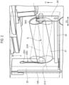
- FIG. 2 and 3 are diagrams for describing an example of a rotator 21 in the weighing apparatus 1 according to the first embodiment.
- the weighing apparatus 1 includes a distribution table 10, a plurality of supply troughs 11A and 11B, a plurality of pool hoppers 12A and 12B, and a sorting mechanism 20.
- the distribution table 10 receives articles given from outside and distributes the articles downstream. Note that, in the present embodiment, as illustrated in FIG. 1 , the distribution table 10 includes a first part 10A frustoconical in shape and a second part 10B conical in shape on the upper base face of the first part 10A.
- the plurality of supply troughs 11A and 11B is provided corresponding one-to-one to the plurality of pool hoppers 12A and 12B and supplies the articles received from the distribution table 10 to the plurality of pool hoppers 12A and 12B, respectively.
- the supply troughs 11A and 11B are disposed radially.
- the distribution table 10 and the supply troughs 11A and 11B are each vibrated by the drive of a vibrator, so that the articles on the distribution table 10 are supplied to the plurality of pool hoppers 12A and 12B downstream of the supply troughs 11A and 11B, respectively.
- the plurality of pool hoppers 12A and 12B temporarily stores the articles supplied from the supply troughs 11A and 11B, respectively, and then discharges the articles downstream.
- the sorting mechanism 20 is disposed between adjacent pool hoppers (e.g., the pool hoppers 12A and 12B) and sorts an article given from the supply trough 11A or 11B (from outside) into one of the adjacent pool hoppers (e.g., the pool hoppers 12A and 12B).
- the sorting mechanism 20 includes a rotator 21 rotatable around a rotation shaft 21R.
- the rotator 21 is cylindrical in shape, extending along a central axis 21C.
- the rotator 12 is, for example, a roller molded from resin.
- the rotation shaft 21R and the central axis 21C of the rotator 21 are not parallel.
- the rotation shaft 21R and the central axis 21C pass through the center of gravity G of the rotator 21 cylindrical in shape.
- the rotator 21 rotates when an article supplied from the supply trough 11A or 11B abuts on or mounts the rotator 21.
- the rotator 21 does not rotate when no article abuts on the rotator 21.
- the moment of rotation acts on the rotator 21, so that the rotator 21 rotates reliably.
- the rotator 21 rotates reliably, without any motor, to drop the article into either pool hopper (e.g., the pool hopper 12A or 12B).
- the rotation shaft 21R for the rotator 21 can be inhibited from being worn.
- the sorting mechanism 20 includes a bracket 22, a rod 23, and a fastener 24, in addition to the rotator 21.
- the bracket 22 is hooked on the upper end of a coupler 120 coupling the adjacent pool hoppers 12A and 12B together and is secured to the coupler 120.
- the rod 23 has an end attached to the lower end portion of the bracket 22 extending vertically and extends in the extending direction D1 of the rotation shaft 21R.
- the fastener 24 extending vertically is attached to the other end of the rod 23 and extends from the other end in an up direction U.
- an article supplied between the adjacent pool hoppers 12A and 12B can reliably drop into one of the pool hoppers 12A and 12B.
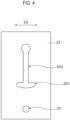
- the cutout 22C extends in a direction D2 orthogonal to the extending direction D1 of a rotation shaft 21R. Specifically, as illustrated in FIG. 4 , the cutout 22C extends gradually upward while extending outward in the direction D2.
- the rotation shaft 21R moves along the cutouts 22C and 24C, so that the article can more reliably drop into either pool hopper (e.g., a pool hopper 12A or 12B).
Landscapes
- Physics & Mathematics (AREA)
- General Physics & Mathematics (AREA)
- Filling Or Emptying Of Bunkers, Hoppers, And Tanks (AREA)
- Sorting Of Articles (AREA)
- Supply Of Fluid Materials To The Packaging Location (AREA)
- Weight Measurement For Supplying Or Discharging Of Specified Amounts Of Material (AREA)
Abstract
Description
- The present invention relates to a weighing apparatus.
- Conventionally, known has been a weighing apparatus including a rotator disposed rotatably at the boundary between adjacent hoppers, in which an article mounted on the rotator drops into either hopper. The rotator corresponds to a roller molded from resin or a rotary blade made of metal.
- When an article mounts such a rotator, typically, the rotator gets unstable and then rotates, so that the article drops into either hopper.
- However, for example, when a flat article like a thigh mounts the rotator in a balanced manner, the rotator does not rotate, so that the article remains on the rotator. In such a case, the article is left between the hoppers for a long time as an undesirable problem.
- Thus, in order to solve the problem, known has been a weighing apparatus including a rotator that is coupled to a motor and rotates based on the motor.
- Patent Literature 1:
JP 2007-198817 A - However, the weighing apparatus described above is expensive in cost and is disadvantageous in cleaning as undesirable problems because the motor is disposed between adjacent hoppers.
- Thus, the present invention has been made in consideration of the above problems and an object of the present invention is to provide a weighing apparatus enabling an article supplied between adjacent hoppers to drop reliably into either hopper, with a simple configuration.
- A weighing apparatus according to an embodiment includes: adjacent hoppers; and a sorting mechanism disposed between the adjacent hoppers, the sorting mechanism being configured to sort an article given from outside into one of the adjacent hoppers, in which the sorting mechanism includes a rotator rotatable around a rotation shaft, the rotation shaft and a central axis of the rotator are not parallel, the rotator rotates when the article abuts on the rotator, and the rotator does not rotate when the article does not abut on the rotator.
- According to the present invention, provided can be a weighing apparatus enabling an article supplied between adjacent hoppers to drop reliably into either hopper, with a simple configuration.
-
-
FIG. 1 a diagram for describing an example of a configuration of a weighing apparatus 1 according to an embodiment. -
FIG. 2 is a diagram for describing an example of arotator 21 in the weighing apparatus 1 according to the embodiment. -
FIG. 3 is a diagram for describing an example of arotator 21 in the weighing apparatus 1 according to the embodiment. -
FIG. 4 is a diagram for describing a weighing apparatus 1 according to a modification 1. -
FIG. 5 is a diagram for describing a weighing apparatus 1 according to a modification 1. -
FIG. 6 is a diagram for describing a weighing apparatus 1 according to a modification 1. - Preferred embodiments of the present invention will be described in detail below with reference to the accompanying drawings. Note that, in the following drawings, the same or similar parts are denoted with the same or similar reference signs. It should be noted that the drawings are schematic and, for example, the ratio between each dimension is different from the real. Therefore, for example, specific dimensions should be understood in consideration of the following descriptions. In addition, parts between each drawing may be different in dimensional relationship or dimensional ratio. In the present specification and the drawings, constituents substantially identical in function or configuration are denoted with the same reference signs and thus duplicate descriptions thereof will be omitted. In addition, any constituents not directly related to the present invention are not illustrated.
- A weighing apparatus 1 according to a first embodiment of the present invention will be described below with reference to
FIGS. 1 to 3 .FIG. 1 a diagram for describing an example of a configuration of a weighing apparatus 1 according to a first embodiment, andFIG. 2 and3 are diagrams for describing an example of arotator 21 in the weighing apparatus 1 according to the first embodiment. - As illustrated in
FIG. 1 , the weighing apparatus 1 according to the present embodiment includes a distribution table 10, a plurality ofsupply troughs pool hoppers sorting mechanism 20. - The distribution table 10 receives articles given from outside and distributes the articles downstream. Note that, in the present embodiment, as illustrated in
FIG. 1 , the distribution table 10 includes afirst part 10A frustoconical in shape and asecond part 10B conical in shape on the upper base face of thefirst part 10A. - The plurality of
supply troughs pool hoppers pool hoppers supply troughs - For example, the distribution table 10 and the
supply troughs pool hoppers supply troughs - The plurality of
pool hoppers supply troughs - The
sorting mechanism 20 is disposed between adjacent pool hoppers (e.g., thepool hoppers supply trough pool hoppers - As illustrated in
FIGS. 1 to 3 , thesorting mechanism 20 includes arotator 21 rotatable around arotation shaft 21R. As illustrated inFIGS. 2 and3 , therotator 21 is cylindrical in shape, extending along acentral axis 21C. The rotator 12 is, for example, a roller molded from resin. - As illustrated in
FIGS. 2 and3 , therotation shaft 21R and thecentral axis 21C of therotator 21 are not parallel. In addition, therotation shaft 21R and thecentral axis 21C pass through the center of gravity G of therotator 21 cylindrical in shape. - Thus, the
rotator 21 rotates when an article supplied from thesupply trough rotator 21. Therotator 21 does not rotate when no article abuts on therotator 21. - That is, since the
rotation shaft 21R intersects the central axis (symmetrical axis) 21C of therotator 21 at the center of gravity G of therotator 21, when no article mounts therotator 21, the center of gravity G of therotator 21 is located on the central axis (symmetrical axis) 21C. Thus, even when vibrations are applied to therotator 21, the symmetry with respect to the position of the center of gravity G remains kept, leading to no rotation. However, when an article mounts therotator 21, the position of the center of gravity of therotator 21 involving the article deviates from the central axis (symmetrical axis) 21C of therotator 21. Due to the deviation, the moment of rotation acts on therotator 21, so that therotator 21 rotates reliably. Thus, when an article mounts or comes in contact with therotator 21, therotator 21 rotates reliably, without any motor, to drop the article into either pool hopper (e.g., the pool hopper 12A or 12B). - Since the
rotator 21 does not rotate when no article abuts on therotator 21, therotation shaft 21R for therotator 21 can be inhibited from being worn. - Specifically, as illustrated in
FIGS. 2 and3 , thesorting mechanism 20 includes abracket 22, arod 23, and afastener 24, in addition to therotator 21. - As illustrated in
FIGS. 2 and3 , thebracket 22 is hooked on the upper end of acoupler 120 coupling theadjacent pool hoppers coupler 120. - As illustrated in
FIG. 2 , therod 23 has an end attached to the lower end portion of thebracket 22 extending vertically and extends in the extending direction D1 of therotation shaft 21R. As illustrated inFIG. 2 , thefastener 24 extending vertically is attached to the other end of therod 23 and extends from the other end in an up direction U. - As illustrated in
FIG. 2 , after an end of therotation shaft 21R for therotator 21 is inserted through a large-diameter hole 22U at the upper end portion of agroove 22G of thebracket 22 and the other end is inserted in anopening 240 in the up direction U provided in thefastener 24, respective ring-shaped grooves, not illustrated, at both ends of therotation shaft 21R detachably fit thegroove 22G and theopening 240. - In a case where articles are perishable products, when the operation is terminated, every part having had contact with the articles requires detaching from the apparatus body and cleaning. The configuration above facilitates disassembly and cleaning, so that a reduction can be made in the time required for cleaning.
- As described above, according to the present embodiment, due to a simple configuration without any motor, an article supplied between the
adjacent pool hoppers pool hoppers - Modification 1 of the present invention will be described below with reference to
FIGS. 4 to 6 . - As illustrated in
FIG. 4 , according to Modification 1, abracket 22 has agroove 22G having its lower end portion provided with acutout 22C. - As illustrated in
FIG. 4 , thecutout 22C extends in a direction D2 orthogonal to the extending direction D1 of arotation shaft 21R. Specifically, as illustrated inFIG. 4 , thecutout 22C extends gradually upward while extending outward in the direction D2. - As illustrated in
FIG. 5 , according to Modification 1, afastener 24 has anopening 240 having its lower end portion provided with acutout 24C. - As illustrated in
FIG. 5 , thecutout 24C extends in the direction D2 described above. Specifically, as illustrated inFIG. 5 , thecutout 24C extends gradually upward while extending outward in the direction D2. Thecutout 22C and thecutout 24C may be identical in shape. - According to the configuration above, when an article mounts a
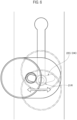
rotator 21, therotator 21 rotates as described above. In addition, as illustrated inFIG. 6 , therotation shaft 21R moves along thecutouts pool hopper - The present invention has been described in detail with the embodiments above. It is obvious to those skilled in the art that the present invention is not limited to the embodiments in the present specification. The present invention can be carried out in aspects modified and altered without departing from the gist and scope of the present invention in the claims. Therefore, the present specification is intended for exemplificative description and thus does not have any limitative meanings to the present invention.
-
- 1 ... Weighing apparatus
- 10 ... distribution table
- 11A, 11B ... Supply troughs
- 12A, 12B ... Pool hoppers
- 20 ... Sorting mechanism
- 21 ... Rotator
- 21R ... Rotation shaft
- 21C ... Central axis
- 22 ... Bracket
- 22G ... Groove
- 23 ... Rod
- 24 ... Fastener
- 24O ... Opening
- 120 ... Coupler
Claims (3)
- A weighing apparatus comprising:adjacent hoppers; anda sorting mechanism disposed between the adjacent hoppers, the sorting mechanism sorting an article given from outside into one of the adjacent hoppers, whereinthe sorting mechanism includes a rotator rotatable around a rotation shaft,the rotation shaft and a central axis of the rotator are not parallel,the rotator rotates when the article abuts on the rotator, andthe rotator does not rotate when the article does not abut on the rotator.
- The weighing apparatus according to claim 1, wherein
the rotator does not rotate at any position for rotation when the article does not abut on the rotator. - The weighing apparatus according to claim 1 or 2, whereinthe sorting mechanism includes:a bracket hooked on an upper end of a coupler that couples the adjacent hoppers together, the bracket being secured to the coupler;a rod attached to the bracket, the rod extending in an extending direction of the rotation shaft; anda fastener attached to the rod, the fastener extending in an up direction, andthe rotation shaft for the rotator is inserted in a groove of the bracket and is inserted in an opening in the up direction provided in the fastener.
Applications Claiming Priority (1)
| Application Number | Priority Date | Filing Date | Title |
|---|---|---|---|
| JP2023022693A JP2024116865A (en) | 2023-02-16 | 2023-02-16 | Weighing system |
Publications (2)
| Publication Number | Publication Date |
|---|---|
| EP4417946A1 true EP4417946A1 (en) | 2024-08-21 |
| EP4417946B1 EP4417946B1 (en) | 2025-05-07 |
Family
ID=89901095
Family Applications (1)
| Application Number | Title | Priority Date | Filing Date |
|---|---|---|---|
| EP24157116.5A Active EP4417946B1 (en) | 2023-02-16 | 2024-02-12 | Weighing apparatus |
Country Status (4)
| Country | Link |
|---|---|
| EP (1) | EP4417946B1 (en) |
| JP (1) | JP2024116865A (en) |
| CN (1) | CN118500512A (en) |
| DK (1) | DK4417946T3 (en) |
Citations (3)
| Publication number | Priority date | Publication date | Assignee | Title |
|---|---|---|---|---|
| JP2007198817A (en) | 2006-01-25 | 2007-08-09 | Ishida Co Ltd | Combination weighing device |
| US20090101478A1 (en) * | 2007-10-23 | 2009-04-23 | Christopher Dale | Inline conveyor scale |
| US20220244094A1 (en) * | 2017-05-02 | 2022-08-04 | Cabinplant International A/S | Methods and apparatus for feeding, weighing, and collecting solid food products with sticky coatings |
-
2023
- 2023-02-16 JP JP2023022693A patent/JP2024116865A/en active Pending
-
2024
- 2024-01-25 CN CN202410107215.7A patent/CN118500512A/en active Pending
- 2024-02-12 EP EP24157116.5A patent/EP4417946B1/en active Active
- 2024-02-12 DK DK24157116.5T patent/DK4417946T3/en active
Patent Citations (3)
| Publication number | Priority date | Publication date | Assignee | Title |
|---|---|---|---|---|
| JP2007198817A (en) | 2006-01-25 | 2007-08-09 | Ishida Co Ltd | Combination weighing device |
| US20090101478A1 (en) * | 2007-10-23 | 2009-04-23 | Christopher Dale | Inline conveyor scale |
| US20220244094A1 (en) * | 2017-05-02 | 2022-08-04 | Cabinplant International A/S | Methods and apparatus for feeding, weighing, and collecting solid food products with sticky coatings |
Also Published As
| Publication number | Publication date |
|---|---|
| EP4417946B1 (en) | 2025-05-07 |
| CN118500512A (en) | 2024-08-16 |
| DK4417946T3 (en) | 2025-05-26 |
| US20240280398A1 (en) | 2024-08-22 |
| JP2024116865A (en) | 2024-08-28 |
Similar Documents
| Publication | Publication Date | Title |
|---|---|---|
| EP3112825B1 (en) | Combination weighing apparatus | |
| US6860379B2 (en) | Component arranging and delivering apparatus | |
| JP2013063850A (en) | Powder feeder | |
| US11027929B2 (en) | Modular bearing device for at least one pair of gripping arms, and method for assembling same | |
| US9205518B2 (en) | Washer arranging apparatus, washer arranging system, and washer arranging method | |
| JP2017047976A (en) | Method of controlling belt conveyer system | |
| WO2018036477A1 (en) | Production equipment for manufacturing products in form of sheets or bulks, and method therefor | |
| EP4417946B1 (en) | Weighing apparatus | |
| US12631480B2 (en) | Weighing apparatus | |
| JP2013049478A (en) | Powder bridge prevention device and powder feeding device | |
| JP2019064807A (en) | Supply device for powdery granular material | |
| JP6892107B2 (en) | Supply device and supply method of powder and granular material | |
| US10669107B2 (en) | Carrying apparatus and cam control shaft for gripping devices | |
| WO2020184632A1 (en) | Combination weighing device | |
| CN116767817B (en) | Combined metering device | |
| CN211732816U (en) | Screw conveyer | |
| EP1840052A1 (en) | Conveying device and combination metering apparatus having the same | |
| EP3572904B1 (en) | Method and dispensing apparatus for dispensing a powder and/or granular material | |
| US20170211967A1 (en) | Combination weighing device | |
| WO2021134758A1 (en) | Material conveying mechanism and weighing system | |
| JP2809898B2 (en) | Method and apparatus for supplying powder and granular material in rotary packaging machine | |
| EP4589267A1 (en) | Combination weighing apparatus | |
| CN206871391U (en) | A kind of distributing conveying mechanism of tablet packaging machine | |
| EP3171141B1 (en) | Combination weighing device | |
| CN206032751U (en) | A reversible vibrating feeding device |
Legal Events
| Date | Code | Title | Description |
|---|---|---|---|
| PUAI | Public reference made under article 153(3) epc to a published international application that has entered the european phase |
Free format text: ORIGINAL CODE: 0009012 |
|
| STAA | Information on the status of an ep patent application or granted ep patent |
Free format text: STATUS: REQUEST FOR EXAMINATION WAS MADE |
|
| 17P | Request for examination filed |
Effective date: 20240212 |
|
| AK | Designated contracting states |
Kind code of ref document: A1 Designated state(s): AL AT BE BG CH CY CZ DE DK EE ES FI FR GB GR HR HU IE IS IT LI LT LU LV MC ME MK MT NL NO PL PT RO RS SE SI SK SM TR |
|
| GRAP | Despatch of communication of intention to grant a patent |
Free format text: ORIGINAL CODE: EPIDOSNIGR1 |
|
| STAA | Information on the status of an ep patent application or granted ep patent |
Free format text: STATUS: GRANT OF PATENT IS INTENDED |
|
| RIC1 | Information provided on ipc code assigned before grant |
Ipc: G01G 19/393 20060101AFI20241125BHEP |
|
| INTG | Intention to grant announced |
Effective date: 20241205 |
|
| GRAS | Grant fee paid |
Free format text: ORIGINAL CODE: EPIDOSNIGR3 |
|
| GRAA | (expected) grant |
Free format text: ORIGINAL CODE: 0009210 |
|
| STAA | Information on the status of an ep patent application or granted ep patent |
Free format text: STATUS: THE PATENT HAS BEEN GRANTED |
|
| AK | Designated contracting states |
Kind code of ref document: B1 Designated state(s): AL AT BE BG CH CY CZ DE DK EE ES FI FR GB GR HR HU IE IS IT LI LT LU LV MC ME MK MT NL NO PL PT RO RS SE SI SK SM TR |
|
| REG | Reference to a national code |
Ref country code: GB Ref legal event code: FG4D |
|
| REG | Reference to a national code |
Ref country code: CH Ref legal event code: EP |
|
| REG | Reference to a national code |
Ref country code: DK Ref legal event code: T3 Effective date: 20250522 |
|
| REG | Reference to a national code |
Ref country code: DE Ref legal event code: R096 Ref document number: 602024000100 Country of ref document: DE |
|
| REG | Reference to a national code |
Ref country code: IE Ref legal event code: FG4D |
|
| REG | Reference to a national code |
Ref country code: NL Ref legal event code: MP Effective date: 20250507 |
|
| PG25 | Lapsed in a contracting state [announced via postgrant information from national office to epo] |
Ref country code: FI Free format text: LAPSE BECAUSE OF FAILURE TO SUBMIT A TRANSLATION OF THE DESCRIPTION OR TO PAY THE FEE WITHIN THE PRESCRIBED TIME-LIMIT Effective date: 20250507 Ref country code: PT Free format text: LAPSE BECAUSE OF FAILURE TO SUBMIT A TRANSLATION OF THE DESCRIPTION OR TO PAY THE FEE WITHIN THE PRESCRIBED TIME-LIMIT Effective date: 20250908 Ref country code: ES Free format text: LAPSE BECAUSE OF FAILURE TO SUBMIT A TRANSLATION OF THE DESCRIPTION OR TO PAY THE FEE WITHIN THE PRESCRIBED TIME-LIMIT Effective date: 20250507 |
|
| REG | Reference to a national code |
Ref country code: LT Ref legal event code: MG9D |
|
| PG25 | Lapsed in a contracting state [announced via postgrant information from national office to epo] |
Ref country code: NO Free format text: LAPSE BECAUSE OF FAILURE TO SUBMIT A TRANSLATION OF THE DESCRIPTION OR TO PAY THE FEE WITHIN THE PRESCRIBED TIME-LIMIT Effective date: 20250807 Ref country code: GR Free format text: LAPSE BECAUSE OF FAILURE TO SUBMIT A TRANSLATION OF THE DESCRIPTION OR TO PAY THE FEE WITHIN THE PRESCRIBED TIME-LIMIT Effective date: 20250808 |
|
| PG25 | Lapsed in a contracting state [announced via postgrant information from national office to epo] |
Ref country code: NL Free format text: LAPSE BECAUSE OF FAILURE TO SUBMIT A TRANSLATION OF THE DESCRIPTION OR TO PAY THE FEE WITHIN THE PRESCRIBED TIME-LIMIT Effective date: 20250507 Ref country code: PL Free format text: LAPSE BECAUSE OF FAILURE TO SUBMIT A TRANSLATION OF THE DESCRIPTION OR TO PAY THE FEE WITHIN THE PRESCRIBED TIME-LIMIT Effective date: 20250507 |
|
| REG | Reference to a national code |
Ref country code: AT Ref legal event code: MK05 Ref document number: 1792912 Country of ref document: AT Kind code of ref document: T Effective date: 20250507 |
|
| PG25 | Lapsed in a contracting state [announced via postgrant information from national office to epo] |
Ref country code: BG Free format text: LAPSE BECAUSE OF FAILURE TO SUBMIT A TRANSLATION OF THE DESCRIPTION OR TO PAY THE FEE WITHIN THE PRESCRIBED TIME-LIMIT Effective date: 20250507 |
|
| PG25 | Lapsed in a contracting state [announced via postgrant information from national office to epo] |
Ref country code: HR Free format text: LAPSE BECAUSE OF FAILURE TO SUBMIT A TRANSLATION OF THE DESCRIPTION OR TO PAY THE FEE WITHIN THE PRESCRIBED TIME-LIMIT Effective date: 20250507 |
|
| PG25 | Lapsed in a contracting state [announced via postgrant information from national office to epo] |
Ref country code: AT Free format text: LAPSE BECAUSE OF FAILURE TO SUBMIT A TRANSLATION OF THE DESCRIPTION OR TO PAY THE FEE WITHIN THE PRESCRIBED TIME-LIMIT Effective date: 20250507 |
|
| PG25 | Lapsed in a contracting state [announced via postgrant information from national office to epo] |
Ref country code: RS Free format text: LAPSE BECAUSE OF FAILURE TO SUBMIT A TRANSLATION OF THE DESCRIPTION OR TO PAY THE FEE WITHIN THE PRESCRIBED TIME-LIMIT Effective date: 20250807 |
|
| PG25 | Lapsed in a contracting state [announced via postgrant information from national office to epo] |
Ref country code: IS Free format text: LAPSE BECAUSE OF FAILURE TO SUBMIT A TRANSLATION OF THE DESCRIPTION OR TO PAY THE FEE WITHIN THE PRESCRIBED TIME-LIMIT Effective date: 20250907 |
|
| PG25 | Lapsed in a contracting state [announced via postgrant information from national office to epo] |
Ref country code: LV Free format text: LAPSE BECAUSE OF FAILURE TO SUBMIT A TRANSLATION OF THE DESCRIPTION OR TO PAY THE FEE WITHIN THE PRESCRIBED TIME-LIMIT Effective date: 20250507 |
|
| PG25 | Lapsed in a contracting state [announced via postgrant information from national office to epo] |
Ref country code: SM Free format text: LAPSE BECAUSE OF FAILURE TO SUBMIT A TRANSLATION OF THE DESCRIPTION OR TO PAY THE FEE WITHIN THE PRESCRIBED TIME-LIMIT Effective date: 20250507 |
|
| PG25 | Lapsed in a contracting state [announced via postgrant information from national office to epo] |
Ref country code: CZ Free format text: LAPSE BECAUSE OF FAILURE TO SUBMIT A TRANSLATION OF THE DESCRIPTION OR TO PAY THE FEE WITHIN THE PRESCRIBED TIME-LIMIT Effective date: 20250507 |
|
| PG25 | Lapsed in a contracting state [announced via postgrant information from national office to epo] |
Ref country code: EE Free format text: LAPSE BECAUSE OF FAILURE TO SUBMIT A TRANSLATION OF THE DESCRIPTION OR TO PAY THE FEE WITHIN THE PRESCRIBED TIME-LIMIT Effective date: 20250507 |
|
| PG25 | Lapsed in a contracting state [announced via postgrant information from national office to epo] |
Ref country code: SK Free format text: LAPSE BECAUSE OF FAILURE TO SUBMIT A TRANSLATION OF THE DESCRIPTION OR TO PAY THE FEE WITHIN THE PRESCRIBED TIME-LIMIT Effective date: 20250507 |
|
| PG25 | Lapsed in a contracting state [announced via postgrant information from national office to epo] |
Ref country code: IT Free format text: LAPSE BECAUSE OF FAILURE TO SUBMIT A TRANSLATION OF THE DESCRIPTION OR TO PAY THE FEE WITHIN THE PRESCRIBED TIME-LIMIT Effective date: 20250507 |
|
| REG | Reference to a national code |
Ref country code: DE Ref legal event code: R097 Ref document number: 602024000100 Country of ref document: DE |
|
| PLBE | No opposition filed within time limit |
Free format text: ORIGINAL CODE: 0009261 |
|
| STAA | Information on the status of an ep patent application or granted ep patent |
Free format text: STATUS: NO OPPOSITION FILED WITHIN TIME LIMIT |
|
| REG | Reference to a national code |
Ref country code: CH Ref legal event code: L10 Free format text: ST27 STATUS EVENT CODE: U-0-0-L10-L00 (AS PROVIDED BY THE NATIONAL OFFICE) Effective date: 20260318 |
|
| PGFP | Annual fee paid to national office [announced via postgrant information from national office to epo] |
Ref country code: DK Payment date: 20260217 Year of fee payment: 3 Ref country code: DE Payment date: 20260217 Year of fee payment: 3 |
|
| 26N | No opposition filed |
Effective date: 20260210 |