EP4417919A1 - Electrode manufacturing facility and electrode manufacturing method - Google Patents
Electrode manufacturing facility and electrode manufacturing method Download PDFInfo
- Publication number
- EP4417919A1 EP4417919A1 EP23217509.1A EP23217509A EP4417919A1 EP 4417919 A1 EP4417919 A1 EP 4417919A1 EP 23217509 A EP23217509 A EP 23217509A EP 4417919 A1 EP4417919 A1 EP 4417919A1
- Authority
- EP
- European Patent Office
- Prior art keywords
- outside air
- exhaust gas
- air inlet
- inlet pipe
- dryer
- Prior art date
- Legal status (The legal status is an assumption and is not a legal conclusion. Google has not performed a legal analysis and makes no representation as to the accuracy of the status listed.)
- Granted
Links
Images

Classifications
-
- B—PERFORMING OPERATIONS; TRANSPORTING
- B05—SPRAYING OR ATOMISING IN GENERAL; APPLYING FLUENT MATERIALS TO SURFACES, IN GENERAL
- B05D—PROCESSES FOR APPLYING FLUENT MATERIALS TO SURFACES, IN GENERAL
- B05D3/00—Pretreatment of surfaces to which liquids or other fluent materials are to be applied; After-treatment of applied coatings, e.g. intermediate treating of an applied coating preparatory to subsequent applications of liquids or other fluent materials
- B05D3/02—Pretreatment of surfaces to which liquids or other fluent materials are to be applied; After-treatment of applied coatings, e.g. intermediate treating of an applied coating preparatory to subsequent applications of liquids or other fluent materials by baking
- B05D3/0254—After-treatment
- B05D3/0272—After-treatment with ovens
-
- F—MECHANICAL ENGINEERING; LIGHTING; HEATING; WEAPONS; BLASTING
- F26—DRYING
- F26B—DRYING SOLID MATERIALS OR OBJECTS BY REMOVING LIQUID THEREFROM
- F26B13/00—Machines and apparatus for drying fabrics, fibres, yarns, or other materials in long lengths, with progressive movement
- F26B13/001—Drying and oxidising yarns, ribbons or the like
- F26B13/002—Drying coated, e.g. enamelled, varnished, wires
-
- B—PERFORMING OPERATIONS; TRANSPORTING
- B01—PHYSICAL OR CHEMICAL PROCESSES OR APPARATUS IN GENERAL
- B01D—SEPARATION
- B01D53/00—Separation of gases or vapours; Recovering vapours of volatile solvents from gases; Chemical or biological purification of waste gases, e.g. engine exhaust gases, smoke, fumes, flue gases, aerosols
- B01D53/14—Separation of gases or vapours; Recovering vapours of volatile solvents from gases; Chemical or biological purification of waste gases, e.g. engine exhaust gases, smoke, fumes, flue gases, aerosols by absorption
- B01D53/1487—Removing organic compounds
-
- B—PERFORMING OPERATIONS; TRANSPORTING
- B01—PHYSICAL OR CHEMICAL PROCESSES OR APPARATUS IN GENERAL
- B01D—SEPARATION
- B01D53/00—Separation of gases or vapours; Recovering vapours of volatile solvents from gases; Chemical or biological purification of waste gases, e.g. engine exhaust gases, smoke, fumes, flue gases, aerosols
- B01D53/14—Separation of gases or vapours; Recovering vapours of volatile solvents from gases; Chemical or biological purification of waste gases, e.g. engine exhaust gases, smoke, fumes, flue gases, aerosols by absorption
- B01D53/18—Absorbing units; Liquid distributors therefor
-
- B—PERFORMING OPERATIONS; TRANSPORTING
- B01—PHYSICAL OR CHEMICAL PROCESSES OR APPARATUS IN GENERAL
- B01D—SEPARATION
- B01D53/00—Separation of gases or vapours; Recovering vapours of volatile solvents from gases; Chemical or biological purification of waste gases, e.g. engine exhaust gases, smoke, fumes, flue gases, aerosols
- B01D53/26—Drying gases or vapours
-
- F—MECHANICAL ENGINEERING; LIGHTING; HEATING; WEAPONS; BLASTING
- F26—DRYING
- F26B—DRYING SOLID MATERIALS OR OBJECTS BY REMOVING LIQUID THEREFROM
- F26B13/00—Machines and apparatus for drying fabrics, fibres, yarns, or other materials in long lengths, with progressive movement
- F26B13/10—Arrangements for feeding, heating or supporting materials; Controlling movement, tension or position of materials
-
- F—MECHANICAL ENGINEERING; LIGHTING; HEATING; WEAPONS; BLASTING
- F26—DRYING
- F26B—DRYING SOLID MATERIALS OR OBJECTS BY REMOVING LIQUID THEREFROM
- F26B21/00—Arrangements for supplying or controlling air or other gases for drying solid materials or objects
- F26B21/20—Circulating air or gases in closed cycles, e.g. wholly within the drying enclosure
- F26B21/202—Circulating air or gases in closed cycles, e.g. wholly within the drying enclosure with means for changing the flow pattern, e.g. by reversing gas flow or by moving the materials or objects through subsequent compartments, at least two of which have a different flow direction
- F26B21/208—Circulating air or gases in closed cycles, e.g. wholly within the drying enclosure with means for changing the flow pattern, e.g. by reversing gas flow or by moving the materials or objects through subsequent compartments, at least two of which have a different flow direction by air valves, movable baffles or nozzle arrangements
-
- F—MECHANICAL ENGINEERING; LIGHTING; HEATING; WEAPONS; BLASTING
- F26—DRYING
- F26B—DRYING SOLID MATERIALS OR OBJECTS BY REMOVING LIQUID THEREFROM
- F26B21/00—Arrangements for supplying or controlling air or other gases for drying solid materials or objects
- F26B21/20—Circulating air or gases in closed cycles, e.g. wholly within the drying enclosure
- F26B21/25—Circulating air or gases in closed cycles, e.g. wholly within the drying enclosure partly outside the drying enclosure
-
- F—MECHANICAL ENGINEERING; LIGHTING; HEATING; WEAPONS; BLASTING
- F26—DRYING
- F26B—DRYING SOLID MATERIALS OR OBJECTS BY REMOVING LIQUID THEREFROM
- F26B21/00—Arrangements for supplying or controlling air or other gases for drying solid materials or objects
- F26B21/30—Controlling, e.g. regulating, parameters of gas supply
-
- F—MECHANICAL ENGINEERING; LIGHTING; HEATING; WEAPONS; BLASTING
- F26—DRYING
- F26B—DRYING SOLID MATERIALS OR OBJECTS BY REMOVING LIQUID THEREFROM
- F26B21/00—Arrangements for supplying or controlling air or other gases for drying solid materials or objects
- F26B21/30—Controlling, e.g. regulating, parameters of gas supply
- F26B21/33—Humidity
-
- F—MECHANICAL ENGINEERING; LIGHTING; HEATING; WEAPONS; BLASTING
- F26—DRYING
- F26B—DRYING SOLID MATERIALS OR OBJECTS BY REMOVING LIQUID THEREFROM
- F26B21/00—Arrangements for supplying or controlling air or other gases for drying solid materials or objects
- F26B21/30—Controlling, e.g. regulating, parameters of gas supply
- F26B21/35—Temperature; Pressure
-
- F—MECHANICAL ENGINEERING; LIGHTING; HEATING; WEAPONS; BLASTING
- F26—DRYING
- F26B—DRYING SOLID MATERIALS OR OBJECTS BY REMOVING LIQUID THEREFROM
- F26B21/00—Arrangements for supplying or controlling air or other gases for drying solid materials or objects
- F26B21/30—Controlling, e.g. regulating, parameters of gas supply
- F26B21/37—Velocity of flow; Quantity of flow
-
- F—MECHANICAL ENGINEERING; LIGHTING; HEATING; WEAPONS; BLASTING
- F26—DRYING
- F26B—DRYING SOLID MATERIALS OR OBJECTS BY REMOVING LIQUID THEREFROM
- F26B21/00—Arrangements for supplying or controlling air or other gases for drying solid materials or objects
- F26B21/40—Arrangements for supplying or controlling air or other gases for drying solid materials or objects using gases other than air
- F26B21/45—Arrangements for supplying or controlling air or other gases for drying solid materials or objects using gases other than air using steam
- F26B21/452—Arrangements for supplying or controlling air or other gases for drying solid materials or objects using gases other than air using steam characterised by the steam generating means
-
- F—MECHANICAL ENGINEERING; LIGHTING; HEATING; WEAPONS; BLASTING
- F26—DRYING
- F26B—DRYING SOLID MATERIALS OR OBJECTS BY REMOVING LIQUID THEREFROM
- F26B23/00—Heating arrangements
- F26B23/001—Heating arrangements using waste heat
- F26B23/002—Heating arrangements using waste heat recovered from dryer exhaust gases
-
- F—MECHANICAL ENGINEERING; LIGHTING; HEATING; WEAPONS; BLASTING
- F26—DRYING
- F26B—DRYING SOLID MATERIALS OR OBJECTS BY REMOVING LIQUID THEREFROM
- F26B23/00—Heating arrangements
- F26B23/02—Heating arrangements using combustion heating
-
- F—MECHANICAL ENGINEERING; LIGHTING; HEATING; WEAPONS; BLASTING
- F26—DRYING
- F26B—DRYING SOLID MATERIALS OR OBJECTS BY REMOVING LIQUID THEREFROM
- F26B23/00—Heating arrangements
- F26B23/04—Heating arrangements using electric heating
-
- F—MECHANICAL ENGINEERING; LIGHTING; HEATING; WEAPONS; BLASTING
- F26—DRYING
- F26B—DRYING SOLID MATERIALS OR OBJECTS BY REMOVING LIQUID THEREFROM
- F26B25/00—Details of general application not covered by group F26B21/00 or F26B23/00
- F26B25/005—Treatment of dryer exhaust gases
- F26B25/006—Separating volatiles, e.g. recovering solvents from dryer exhaust gases
-
- F—MECHANICAL ENGINEERING; LIGHTING; HEATING; WEAPONS; BLASTING
- F26—DRYING
- F26B—DRYING SOLID MATERIALS OR OBJECTS BY REMOVING LIQUID THEREFROM
- F26B25/00—Details of general application not covered by group F26B21/00 or F26B23/00
- F26B25/02—Applications of driving mechanisms, not covered by another subclass
-
- F—MECHANICAL ENGINEERING; LIGHTING; HEATING; WEAPONS; BLASTING
- F26—DRYING
- F26B—DRYING SOLID MATERIALS OR OBJECTS BY REMOVING LIQUID THEREFROM
- F26B3/00—Drying solid materials or objects by processes involving the application of heat
- F26B3/02—Drying solid materials or objects by processes involving the application of heat by convection, i.e. heat being conveyed from a heat source to the materials or objects to be dried by a gas or vapour, e.g. air
- F26B3/04—Drying solid materials or objects by processes involving the application of heat by convection, i.e. heat being conveyed from a heat source to the materials or objects to be dried by a gas or vapour, e.g. air the gas or vapour circulating over or surrounding the materials or objects to be dried
-
- H—ELECTRICITY
- H01—ELECTRIC ELEMENTS
- H01M—PROCESSES OR MEANS, e.g. BATTERIES, FOR THE DIRECT CONVERSION OF CHEMICAL ENERGY INTO ELECTRICAL ENERGY
- H01M10/00—Secondary cells; Manufacture thereof
- H01M10/05—Accumulators with non-aqueous electrolyte
- H01M10/052—Li-accumulators
-
- H—ELECTRICITY
- H01—ELECTRIC ELEMENTS
- H01M—PROCESSES OR MEANS, e.g. BATTERIES, FOR THE DIRECT CONVERSION OF CHEMICAL ENERGY INTO ELECTRICAL ENERGY
- H01M10/00—Secondary cells; Manufacture thereof
- H01M10/05—Accumulators with non-aqueous electrolyte
- H01M10/052—Li-accumulators
- H01M10/0525—Rocking-chair batteries, i.e. batteries with lithium insertion or intercalation in both electrodes; Lithium-ion batteries
-
- H—ELECTRICITY
- H01—ELECTRIC ELEMENTS
- H01M—PROCESSES OR MEANS, e.g. BATTERIES, FOR THE DIRECT CONVERSION OF CHEMICAL ENERGY INTO ELECTRICAL ENERGY
- H01M4/00—Electrodes
- H01M4/02—Electrodes composed of, or comprising, active material
- H01M4/04—Processes of manufacture in general
- H01M4/0402—Methods of deposition of the material
- H01M4/0404—Methods of deposition of the material by coating on electrode collectors
-
- H—ELECTRICITY
- H01—ELECTRIC ELEMENTS
- H01M—PROCESSES OR MEANS, e.g. BATTERIES, FOR THE DIRECT CONVERSION OF CHEMICAL ENERGY INTO ELECTRICAL ENERGY
- H01M4/00—Electrodes
- H01M4/02—Electrodes composed of, or comprising, active material
- H01M4/04—Processes of manufacture in general
- H01M4/0471—Processes of manufacture in general involving thermal treatment, e.g. firing, sintering, backing particulate active material, thermal decomposition, pyrolysis
-
- H—ELECTRICITY
- H01—ELECTRIC ELEMENTS
- H01M—PROCESSES OR MEANS, e.g. BATTERIES, FOR THE DIRECT CONVERSION OF CHEMICAL ENERGY INTO ELECTRICAL ENERGY
- H01M4/00—Electrodes
- H01M4/02—Electrodes composed of, or comprising, active material
- H01M4/13—Electrodes for accumulators with non-aqueous electrolyte, e.g. for lithium-accumulators; Processes of manufacture thereof
- H01M4/139—Processes of manufacture
-
- Y—GENERAL TAGGING OF NEW TECHNOLOGICAL DEVELOPMENTS; GENERAL TAGGING OF CROSS-SECTIONAL TECHNOLOGIES SPANNING OVER SEVERAL SECTIONS OF THE IPC; TECHNICAL SUBJECTS COVERED BY FORMER USPC CROSS-REFERENCE ART COLLECTIONS [XRACs] AND DIGESTS
- Y02—TECHNOLOGIES OR APPLICATIONS FOR MITIGATION OR ADAPTATION AGAINST CLIMATE CHANGE
- Y02E—REDUCTION OF GREENHOUSE GAS [GHG] EMISSIONS, RELATED TO ENERGY GENERATION, TRANSMISSION OR DISTRIBUTION
- Y02E60/00—Enabling technologies; Technologies with a potential or indirect contribution to GHG emissions mitigation
- Y02E60/10—Energy storage using batteries
Definitions
- the present invention relates to an electrode manufacturing facility and a method of manufacturing electrodes.
- JP 2012-097917 A discloses a dryer apparatus that dries a substrate material having a slurry coating film while conveying the substrate material.
- the dryer apparatus disclosed in JP 2012-097917 A is equipped with a drying furnace for drying the coating film on the substrate material and an exhaust port for expelling the gas inside the drying furnace out of the drying furnace.
- the drying furnace includes a plurality of dry zones having different dry atmospheres from each other along a conveying direction of the substrate material.
- the exhaust port of the drying furnace is disposed downstream of the most upstream one of the plurality of dry zones.
- JP 2008-114203 A discloses a method of collecting an inorganic solvent.
- the organic solvent is contained in an exhaust gas in the drying step, so it is necessary to collect the organic solvent.
- Methods of collecting an organic solvent include a dry type method and a wet type method.
- a dry type process for example, the exhaust gas in the drying step is cooled with a cooling water or the like by an indirect heat exchanger to condense and collect a solvent component within the exhaust gas.
- a wet type process involves a gas absorption method using water as an absorbent.
- the exhaust gas is introduced into an absorption tower in which water is sprayed, to thereby cause a solvent component in the exhaust gas to be absorbed into water.
- the present inventors believe that, for a method of collecting an organic solvent from the exhaust gas after the drying, a wet type process, which causes water to absorb the organic solvent, is advantageous over a dry type process, in which the exhaust gas needs to be cooled to a level at which the organic solvent condenses. Accordingly, the present inventors intend to reduce the manufacturing costs including the collecting of an organic solvent with a wet type process.
- an electrode manufacturing facility includes a dryer, a solvent collection device, a first pipe, an outside air inlet pipe, a heat exchanger, and a second pipe.
- the dryer includes a drying furnace, a heater, and a conveyor device.
- the heater is a device that heats the air supplied through the outside air inlet pipe and supplies the air to the drying furnace.
- the conveyor device is a device that conveys a sheet-shaped current collector coated with a mixture slurry in which electrode active material particles are dispersed in an organic solvent, along a predetermined conveyance passage in the drying furnace.
- the solvent collection device is a device that causes the organic solvent contained in an exhaust gas expelled from the dryer to dissolve into water to collect the organic solvent.
- the first pipe is a pipe that sends the exhaust gas expelled from the dryer to the solvent collection device.
- the outside air inlet pipe is a pipe that introduces outside air and sends the outside air to the dryer.
- the heat exchanger is a device configured to exchange heat between the first pipe and the outside air inlet pipe.
- the second pipe is a pipe that is connected to a pipe to which the exhaust gas after having passed through the solvent collection device is expelled and to a portion of the outside air inlet pipe that is upstream of the heat exchanger, and sends at least a portion of the exhaust gas after having passed through the solvent collection device to the outside air inlet pipe.
- the exhaust gas after having passed through the solvent collection device is mixed with the outside air in the outside air inlet pipe and further heat exchanged with the exhaust gas from the dryer by the heat exchanger. This allows the temperature of the outside air introduced to the dryer to be raised in advance, and lowers the energy required by the heater of the dryer.
- the outside air inlet pipe which sends the outside air to the dryer, may further include a heating device disposed downstream of the heat exchanger.
- the outside air inlet pipe, which sends the outside air to the dryer may be provided with a heating device disposed downstream of the heat exchanger without providing the second pipe.
- a method of manufacturing electrodes includes: a drying step of drying a sheet-shaped current collector coated with a mixture slurry in which electrode active material particles are dispersed in an organic solvent; and a solvent collecting step of collecting the organic solvent by spraying water to an exhaust gas produced in the drying step and causing the organic solvent contained in the exhaust gas to dissolve into the water.
- a portion of the exhaust gas after having been sprayed water in the solvent collecting step is mixed with outside air, heat-exchanged with the exhaust gas produced in the drying step, and introduced into the dryer.
- a gas in which outside air is mixed with a portion of the exhaust gas after having been sprayed with water in the solvent collecting step may be heat-exchanged with the exhaust gas produced in the drying step, thereafter further heated, and then introduced into the dryer.
- the method of manufacturing electrodes includes: a drying step of drying a sheet-shaped current collector coated with a mixture slurry in which electrode active material particles are dispersed in an organic solvent; and a solvent collecting step of collecting the organic solvent by spraying water to an exhaust gas produced in the drying step and causing the organic solvent contained in the exhaust gas to dissolve into the water.
- a drying step outside air is heat-exchanged with the exhaust gas produced in the drying step, further heated, and thereafter introduced into a dryer.
- the electrode manufacturing methods as described above are able to raise the temperature of the outside air introduced to the dryer in advance and lower the energy required by the heater of the dryer.
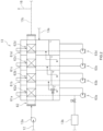
- Fig. 1 is a configuration diagram illustrating the configuration of an electrode manufacturing facility 10.
- the electrode manufacturing facility 10 is used as, for example, manufacturing equipment for manufacturing electrode sheets for use in electricity storage devices, such as lithium-ion secondary batteries and electric double layer capacitors.
- the electrodes manufactured by the electrode manufacturing facility 10 are such that an active material layer containing electrode active material particles is formed on a sheet-shaped substrate material serving as a current collector.
- a method of manufacturing an electrode sheet includes the step of preparing a mixture slurry containing electrode active material particles for a battery electrode, the step of coating a substrate material with the mixture slurry (coating step), and the step of drying the coated mixture slurry (drying step).
- the mixture slurry containing a battery electrode active material includes, for example, electrode active material particles, a binder, and the like that are contained in a solvent.
- the mixture slurry is also referred to as a mixture paste.
- the step of coating a substrate material with a mixture slurry involves coating the prepared mixture slurry onto a sheet-shaped substrate material.
- the electrode sheet substrate material may use a metal foil, such as aluminum foil or copper foil.
- the electrode sheet substrate material is prepared in the form of, for example, a strip-shaped sheet.
- the mixture slurry is supplied through a die or the like onto an electrode sheet conveyed in a roll-to-roll process.
- an active material layer containing electrode active material particles is formed on the electrode sheet by drying the applied mixture slurry.
- the electrode sheet is passed through a drying furnace to dry the mixture slurry applied on the electrode sheet.
- the active material layer that has undergone the drying step is adjusted to have predetermined thickness and density through a pressing step and the like.
- the mainstream of the positive electrode slurry for lithium-ion secondary batteries is one that uses an organic solvent.
- an organic solvent such as N-methyl-2-pyrrolidone (hereinafter referred to as NMP) may be used as a solvent.
- NMP N-methyl-2-pyrrolidone
- the mainstream of the negative electrode slurry for lithium-ion secondary batteries is a slurry that uses styrenebutadiene rubber (hereinafter SBR), which is an aqueous dispersion binder, and water as a solvent.
- SBR styrenebutadiene rubber
- the mixture slurry applied in the coating step contains a required amount of solvent.
- the organic solvent is contained in an exhaust gas in the drying step. For this reason, it is necessary to collect the organic solvent.
- the electrode manufacturing facility 10 includes a dryer 11, a first pipe 12, a solvent collection device 13, an outside air inlet pipe 14, a heat exchanger 15, a second pipe 16, a heating device 20, and a controller 40.
- the dryer 11 is a device that dries a sheet-shaped current collector coated with a mixture slurry in which electrode active material particles are dispersed in an organic solvent.
- the dryer includes a drying furnace 11a, a heater 11b, and a conveyor device 11c.
- the drying furnace 11a may include a furnace chamber that is surrounded by a heat insulating material. Inside the drying furnace 11a, a dry atmosphere is formed in a closed space. The drying furnace 11a is provided with an inlet 11alinto which the current collector coated with the mixture slurry is introduced, and an outlet 11a2. Inside the drying furnace 11a, a predetermined conveyance passage is provided along which the current collector coated with the mixture slurry is to be conveyed. Inside the drying furnace 11a, a dry atmosphere is formed that is at a temperature at which the solvent contained in the mixture slurry can evaporate, for example, at higher than or equal to 100°C.
- the heater 11b is, for example, a device that heats the air supplied through the outside air inlet pipe 14 and supplies the air into the drying furnace 11a.
- the heater 11b may be composed of, for example, an electric heater. That said, the heater 11b is not limited to an electric heater but may be a gas heater or the like.
- the heater 11b heats up the air supplied through the outside air inlet pipe 14 to a predetermined temperature (for example, 115°C) and supplies the heated air to the drying furnace 11a.
- the conveyor device 11c may be a device that conveys a sheet-shaped current collector coated with a mixture slurry.
- the current collector coated with the mixture slurry may be, for example, a strip-shaped sheet and may be conveyed along the predetermined conveyance passage inside the drying furnace 11a.
- the mixture slurry may be applied onto the current collector before the current collector enters the drying furnace 11a.
- a coating device 11d for applying the mixture slurry onto the current collector is provided upstream of the inlet 11a1 of the drying furnace 11a in the current collector conveyance passage.
- the mixture slurry applied to the current collector may be a slurry in which electrode active material particles are dispersed in an organic solvent (for example, NMP).
- the first pipe 12 is a pipe that sends the exhaust gas expelled from the dryer 11 to the solvent collection device 13.
- the exhaust gas expelled from the dryer 11 contains a solvent component.
- the organic solvent used as the solvent component such as NMP, has a boiling point higher than water. Accordingly, the exhaust gas expelled from the dryer 11 has a temperature of, for example, about 100°C.
- the first pipe 12 is arranged from the drying furnace 11a through the heat exchanger 15 to the solvent collection device 13.
- the first pipe 12 is equipped with a blower fan 12a. The exhaust gas expelled from the dryer 11 is forcibly sent to the solvent collection device 13 by the blower fan 12a.
- the blower fan 12a may be disposed in front of the solvent collection device 13, in the first pipe 12.
- the blower fan 12a is controlled together with a later-described blower fan 14a that is disposed in the outside air inlet pipe 14 so that the drying conditions in the dryer 11 can be optimized.
- the flow velocity of the exhaust gas sent from the dryer 11 to the solvent collection device 13 may be controlled by controlling the blower fan 12a.
- the airflow volumes of the blower fans provided in the facility may be controlled in order to, for example, maintain the conditions in the drying furnace.
- the solvent collection device 13 is a wet-type collection device.
- water is supplied to the solvent collection device 13 through a water supply pipe 13a, and the solvent collection device 13 causes the organic solvent contained in the exhaust gas expelled from the dryer 11 to dissolve into water to collect the organic solvent.
- the organic solvent such as NMP, easily dissolves into water. Therefore, when water is sprinkled in the exhaust gas expelled from the dryer 11, the organic solvent contained in the exhaust gas is absorbed by water and is collected efficiently.
- Fig. 2 is a schematic view of the solvent collection device 13.
- the solvent collection device 13 includes a plurality of collection tanks 61a to 61d that are separated from each other.
- a pipe 62 in which the exhaust gas expelled from the dryer 11 is flowed is passed in upper portions of the collection tanks 61a to 61d.
- the collection tanks 61a to 61d are lined up in that order from the inlet end of the pipe 62 toward the outlet end thereof.
- Mist eliminators 62a to 62d for separating organic solvent from the exhaust gas are filled in the pipe 62.
- the mist eliminators may be composed of, for example, a mesh material called a demister.
- the water to be supplied to the solvent collection device 13 is supplied to each of the collection tanks 61a to 61d.
- the water to be supplied to the solvent collection device 13 may be, for example, pure water or the like such as to be adjusted to required water quality.
- the water is supplied so that the level of the water reserved in each of the collection tanks 61a to 61d reaches a predetermined water level.
- the water may be sprinkled on the mist eliminators 62a to 62d.
- the water reserved in the collection tanks 61a to 61d may be pumped up by pumps 63a to 63d so as to be sprinkled from the top of the collection tanks 61a to 61d.
- the water sprinkled from the top of the collection tanks 61a to 61d is retained in the mist eliminators 62a to 62d.
- the organic solvent contained in the exhaust gas expelled from the dryer 11 is absorbed by the water when the exhaust gas passes through the mist eliminators 62a to 62d.
- the water that has absorbed the organic solvent is collected in the collection tanks 61a to 61d.
- the water collected in the collection tanks 61a to 61d is sent in sequence from the collection tank 61d that is near the outlet end toward the collection tank 61a that is near the inlet end. This means that the concentration of the organic solvent is higher toward the collection tank 61a that is near the inlet end.
- each of the collection tanks 61a to 61d measures the concentration of the organic solvent in the water collected the respective collection tanks 61a to 61d, and when the concentration of the organic solvent reaches a predetermined concentration based on the measured values, a valve is opened to send the water to the next one of the collection tanks.
- the collection tank 61a that is near the inlet end has a higher concentration of organic solvent, and the water is discharged one after another from the solvent collection device 13.
- the water that has absorbed the organic solvent may be distilled by a reprocessing facility 13b or the like, as illustrated in Fig. 1 , so that it can be separated into organic solvent and water.
- the water separated from the organic solvent may be used again in the solvent collection device 13.
- the separated organic solvent may be refined again so that it can be reused.
- the exhaust gas after the organic solvent has been absorbed by water in the solvent collection device 13 is expelled through a pipe 13c.
- the pipe 13c in which the exhaust gas expelled from the solvent collection device 13 is flowed is connected to the second pipe 16, as will be described later.
- the reprocessing facility 13b is provided within the factory. It is also possible that the reprocessing facility 13b may be provided outside the factory, for example.
- a reserve tank for reserving the water that has absorbed the organic solvent may be provided, and the water may be transported with a tank truck or the like to the reprocessing facility 13b outside the factory, where the organic solvent is reprocessed.
- the outside air inlet pipe 14 is a pipe that introduces outside air and sends it to the dryer 11.
- the outside air inlet pipe 14 is arranged so as to pass through the heat exchanger 15 and reach the dryer 11.
- the embodiment shown in Fig. 1 is configured so that a portion of the exhaust gas expelled from the solvent collection device 13 is supplied through the second pipe 16 to the outside air inlet pipe 14.
- the outside air inlet pipe 14 is provided with a blower fan 14a in front of the heat exchanger 15.
- Such a blower fan 14a enables outside air to be sent forcibly from the outside air inlet pipe 14 to the heat exchanger 15.
- the flow velocity of the outside air sent from the outside air inlet pipe 14 to the heat exchanger 15 may be controlled by controlling the blower fan 14a.
- outside air inlet pipe 14 is also provided with a blower fan 14b in front of the dryer 11.
- the blower fan 14b enables outside air to be sent forcibly from the outside air inlet pipe 14 to the dryer 11.
- the flow velocity of the outside air sent from the outside air inlet pipe 14 to the dryer 11 may be controlled by controlling the blower fan 14b.
- the heat exchanger 15 is configured to exchange heat between the first pipe 12 and the outside air inlet pipe 14. Such heat exchanger 15 enables exchange of heat between the exhaust gas expelled from the dryer 11, which flows through the first pipe 12, and the outside air that is introduced from the outside air inlet pipe 14. This allows the temperature of the outside air introduced to the dryer 11 to be raised in advance.
- the exhaust gas expelled from the dryer 11, which flows through the first pipe 12 is passed through the heat exchanger 15 and supplied to the solvent collection device 13.
- the heat exchanger 15 lowers the temperature of the exhaust gas expelled from the dryer 11. In the solvent collection device 13, the lower the temperature of the exhaust gas expelled from the dryer 11, the more easily the solvent contained in the exhaust gas condenses, so the more efficiently the organic solvent can be absorbed by water.
- the second pipe 16 is connected to the pipe 13c in which the exhaust gas expelled from the solvent collection device 13 is flowed, and to a portion of the outside air inlet pipe 14 that is upstream of the heat exchanger 15.
- the second pipe 16 is a pipe that sends at least a portion of the exhaust gas after having passed through the solvent collection device 13 to the outside air inlet pipe 14.
- the second pipe 16 allows a portion of the exhaust gas after having passed through the solvent collection device 13 to be introduced into the outside air inlet pipe 14, then passed through the heat exchanger 15, and supplied to the dryer 11. Because the second pipe 16 allows a portion of the exhaust gas after having passed through the solvent collection device 13 to be introduced into the outside air inlet pipe 14, it is possible to stabilize the temperature of the air supplied to the heat exchanger 15.
- the temperature of the outside air introduced into the outside air inlet pipe 14 is assumed to be an annual average of about 16°C.
- the temperature of the outdoor air introduced into the outdoor air inlet pipe 14 varies depending on the season and time of day. For example, the temperature of the outdoor air can be as high as about 35°C during daytime in summer. On the other hand, the temperature of the outdoor air can be as low as about -2°C during nighttime in winter. Thus, the outside air introduced into the outside air inlet pipe 14 is unstable throughout the year. On the other hand, the exhaust gas expelled from the dryer 11 is at about 100°C.
- the temperature of the exhaust gas lowers in the solvent collection device 13 because the exhaust gas is mixed with the sprinkled water, the exhaust gas expelled from the solvent collection device 13 is kept at about 40°C, which is higher than the temperature of the outside air. Because a portion of the exhaust gas after having passed through the solvent collection device 13 is introduced into the outside air inlet pipe 14 through the second pipe 16, the temperature of the outside air that is introduced into the dryer 11 can be raised, so it is expected to reduce the amount of heat required for heating the outside air with the heater 11b of the dryer 11.
- the temperature of the outside air introduced into the outside air inlet pipe 14 is 16°C and the temperature of the exhaust gas expelled from the dryer 11 is 100°C
- the exhaust gas from the solvent collection device 13 is not introduced from the second pipe 16 and the outside air is heat-exchanged with the heat exchanger 15 as it is.
- the temperature of the outside air having passed through the heat exchanger 15 may become about 41°C.
- This air needs to be turned to be hot air at about 115°C in the dryer 11, so the heater 11b of the dryer 11 requires a considerable amount of heat to heat the outside air.
- the temperature of the air supplied to the heat exchanger 15 can be raised to 29°C. Then, the temperature of the air can be raised to 51°C through the heat exchanger 15. This air needs to be turned to be hot air at about 115°C in the dryer 11. However, because the exhaust gas from the solvent collection device 13 is introduced from the second pipe 16 to the outside air introduced to the outside air inlet pipe 14, the temperature of the introduced air is higher by about 10°C. Thus, it is expected to reduce the amount of heat required for the heater 11b of the dryer 11 to heat the outside air.
- outside air is introduced into the outside air inlet pipe 14, mixed in the outside air inlet pipe 14 with the exhaust gas after having passed through the solvent collection device 13 that is supplied from the second pipe 16, and further heat exchanged with the exhaust gas from the dryer 11 by the heat exchanger 15.
- This makes it possible to use the heat of the exhaust gas from the dryer 11 and to raise the temperature of the outside air to be introduced to the dryer 11 in advance. This lowers the energy required by the heater 11b of the dryer 11.
- the temperature of the exhaust gas expelled from the solvent collection device 13 is stable throughout the year, it is possible to stabilize the temperature of the outside air supplied by the outside air inlet pipe 14.
- the electrode manufacturing facility 10 may further include a regulator valve 16a for regulating the flow rate of the second pipe 16. Because the second pipe 16 is provided with the regulator valve 16a, it is possible to regulate the exhaust gas after having passed through the solvent collection device 13 that is introduced to the outside air inlet pipe 14. This makes it possible to control the temperature and dew point of the gas that flows through the outside air inlet pipe 14.
- a controller 40 may be configured to detect at least one of the temperature and dew point of a gas flowing in the outside air inlet pipe 14 at a part of the second pipe 16 that is downstream of the outside air inlet pipe 14 and upstream of the heat exchanger 15, and execute a process of controlling the degree of opening of the regulator valve 16a based on the detected value. This makes it possible to regulate the amount of the exhaust gas introduced to the outside air inlet pipe 14 through the second pipe 16 while feeding back at least one of the temperature and dew point of the gas flowing in the outside air inlet pipe 14.
- the controller 40 may be configured to detect the temperature or dew point of the gas flowing in the outside air inlet pipe 14 with a sensor 14c provided in the outside air inlet pipe 14 after the exhaust gas after having passed through the solvent collection device 13 has been introduced through the second pipe 16, and to regulate the degree of opening of the regulator valve 16a provided in the second pipe 16.
- the amount of the exhaust gas to be introduced into the outside air inlet pipe 14 through the second pipe 16 may be regulated taking the temperature or dew point of the gas flowing in the outside air inlet pipe 14 into consideration.
- the gas flowing in the outside air inlet pipe 14 is sent to the dryer 11.
- the exhaust gas introduced to the outside air inlet pipe 14 through the second pipe 16 has a high humidity.
- the amount of the exhaust gas to be introduced into the outside air inlet pipe 14 through the second pipe 16 may be regulated taking the dew point of the gas flowing in the outside air inlet pipe 14 into consideration, in addition to the temperature thereof. It is more preferable that the regulator valve 16a for regulating the flow rate of the second pipe 16 be controlled based on the temperature and the dew point of the gas flowing in the outside air inlet pipe 14.
- the degree of opening of the regulator valve 16a may be adjusted so as to increase the amount of the exhaust gas to be introduced into the outside air inlet pipe 14 through the second pipe 16.
- the degree of opening of the regulator valve 16a may be adjusted so as to decrease the amount of the exhaust gas to be introduced into the outside air inlet pipe 14 through the second pipe 16. It is also possible that when the dew point of the gas flowing in the outside air inlet pipe 14 becomes higher than a predetermined dew point, the regulator valve 16a may be adjusted to be closed.
- the degree of opening of the regulator valve 16a may be adjusted so as to increase the amount of the exhaust gas to be introduced into the outside air inlet pipe 14 through the second pipe 16.
- the degree of opening of the regulator valve 16a may be adjusted so as to decrease the amount of the exhaust gas to be introduced into the outside air inlet pipe 14 through the second pipe 16. It is also possible that when the temperature of the gas flowing in the outside air inlet pipe 14 becomes higher than a predetermined temperature, the regulator valve 16a may be adjusted to be closed.
- the controller 40 may be configured to detect the concentration of the organic solvent contained in the exhaust gas flowing in the second pipe 16 at a part of the second pipe 16 that is downstream of the outside air inlet pipe 14 and upstream of the heat exchanger 15, and execute a process of controlling the degree of opening of the regulator valve 16a based on the concentration of the organic solvent that has been detected. This makes it possible to adjust the amount of the exhaust gas to be introduced into the outside air inlet pipe 14 through the second pipe 16 while monitoring the concentration of the organic solvent in the outside air inlet pipe 14.
- the controller 40 may be configured to detect the concentration of the organic solvent in the gas flowing in the outside air inlet pipe 14 with the sensor 14c provided in the outside air inlet pipe 14 after the exhaust gas after having passed through the solvent collection device 13 has been introduced through the second pipe 16, and to regulate the degree of opening of the regulator valve 16a provided in the second pipe 16.
- concentration of the organic solvent exceeds a predetermined concentration in the outside air introduced into the dryer 11
- the concentration of the organic solvent in the outside air to be introduced into the dryer 11 may be restricted to such a level as not to slow down the drying of the mixture slurry in the dryer 11.
- the regulator valve 16a provided in the second pipe 16 may be shut off when the concentration exceeds a predetermined concentration from the viewpoint of safety.
- the degree of opening of the regulator valve 16a provided in the second pipe 16 may be configured to be adjusted based on the concentration of the organic solvent and at least one of the temperature and dew point of the gas flowing in the outside air inlet pipe 14, after the exhaust gas after having passed through the solvent collection device 13 is introduced through the second pipe 16.
- This makes it possible to control the temperature, the dew point, and the organic solvent concentration of the outside air that is introduced into the dryer 11 through the outside air inlet pipe 14.
- the regulator valve 16a provided in the second pipe 16 may be controlled in such a manner that the degree of opening of the regulator valve 16a is adjusted based on at least one of the temperature and dew point and the regulator valve 16a is closed when the concentration of the organic solvent exceeds a predetermined concentration.
- the regulating valve 16a may be controlled with two factors, temperature and dew point.
- the degree of opening of the regulator valve 16a may be prevented from increasing when the dew point exceeds a certain value. This can prevent the degree of opening of the regulator valve 16a from increasing, for example, when the dew point exceeds a certain value even in the case where the temperature of the gas flowing in the outside air inlet pipe 14 is lower than a predetermined value because of temperature control after the exhaust gas after having passed through the solvent collection device 13 is introduced through the second pipe 16. This can prevent the dew point of the gas flowing in the outside air inlet pipe 14 from increasing above a certain value.
- the degree of opening of the regulator valve 16a and the like may be controlled so that the quality of the gas flowing in the outside air inlet pipe 14 that is measured with the sensor 14c can be adjusted to predetermined quality.
- the outside air inlet pipe 14 further includes a heating device 20.
- the heating device 20 is disposed at a portion of the outside air inlet pipe 14, which sends the outside air to the dryer 11, that is downstream of the heat exchanger 15.
- the heating device 20 is a device that heats up the gas sent to the dryer 11 through the outside air inlet pipe 14 at the portion downstream of the heat exchanger 15.
- the heating device 20 includes a heat pump 21 and a heat exchange coil 22.
- the heat exchange coil 22 is disposed in the middle of the outside air inlet pipe 14, and may be a plate type heat exchanger or the like that has sufficient capability of raising the temperature of the outside air inlet pipe 14 to higher than a certain value.
- the heat pump 21 may be a hot water heat pump unit.
- the hot water heat pump unit is, for example, a heat pump unit equipped with a heat transfer medium circulation system including a heat absorbing part and a heat dissipating part.
- the hot water heat pump unit receives heat from a water heat source or an air heat source outside the system by the heat absorbing part and dissipates the heat to a heat transfer system that circulates between the heat pump 21 and the heat exchange coil 22 from the heat dissipating part. This makes it possible to supply required hot water to the heat exchange coil 22.
- the heat exchange coil 22 is supplied with hot water, for example, at about 90°C from the heat pump 21 to heat the gas flowing in the outside air inlet pipe 14. Then, the outside air heated by the heat exchange coil 22 is supplied to the dryer 11.
- the temperature of the gas flowing in the outside air inlet pipe 14 that is expelled from the heat exchanger 15 is about 51°C
- the temperature of the outside air supplied to the dryer 11 can be raised to about 80°C by heating the gas flowing in the outside air inlet pipe 14 through the heating device 20.
- the heat pump 21 is able to utilize a large amount of heat energy with a small amount of input energy.
- the heating device 20 enables the outside air to be further heated and thereafter supplied to the device, so it is possible to significantly reduce the energy required by the heater 11b of the dryer 11.
- the electrode manufacturing facility 10 may be configured to detect the temperature of the gas flowing in the outside air inlet pipe 14 with a sensor 23 provided downstream of the heating device 20 and to control the degree of opening of a regulator valve 24 provided in the heat pump 21.
- the degree of opening of the regulator valve 24 By controlling the degree of opening of the regulator valve 24 based on the temperature of the gas flowing in the outside air inlet pipe 14, the amount of heat transfer medium circulating in the heat pump 21 is controlled so that the gas flowing in the outside air inlet pipe 14 can be heated to a stable temperature.
- the amount of heat exchanged with the gas flowing in the outside air inlet pipe 14 may be adjusted in the heat exchange coil 22 in this way. This makes it possible to adjust the temperature of the outside air supplied to the dryer 11.
- the heat pump 21 is able to cool other heat transfer media.
- the heat pump 21 may use water as the heat transfer medium.
- water as the heat transfer medium makes it possible to obtain cold water at about 10°C, so that it is possible to obtain, as by-products, cooling water for air conditioning or for machines that needs to consume energy to be cooled in external facilities. This provides advantageous effects of further energy reduction.
- heating device 20 herein illustrates an embodiment in which a heat pump and a heat exchange coil that can heat the gas flowing in the outside air inlet pipe 14 efficiently are used. It is sufficient that the heating device 20 may be, but is not limited to, a device that heats up the gas sent to the dryer 11 through the outside air inlet pipe 14 at a location downstream of the heat exchanger 15.
- the capacity required for the heating device 20 can be further reduced by introducing the exhaust gas from the solvent collection device 13 into the outside air inlet pipe 14 through the second pipe 16, moreover heating the gas through the heat exchanger 15, and further heating the gas with the heating device 20. This makes it possible to reduce the size of the heating device 20, and also reduces equipment costs and running costs.
- a method of manufacturing an electrode includes a drying step and a solvent collecting step.
- the drying step is a step of drying a sheet-shaped current collector coated with a mixture slurry in which electrode active material particles are dispersed in an organic solvent.
- the drying step is implemented by the dryer 11.
- the solvent collecting step is a step of collecting the organic solvent by spraying water to an exhaust gas produced in the drying step and causing the organic solvent contained in the exhaust gas to dissolve into the water.
- the solvent collecting step is implemented by the solvent collection device 13.
- a portion of the exhaust gas after having been sprayed water in the solvent collecting step may be mixed with outside air, heat-exchanged with the exhaust gas produced in the drying step, and thereafter introduced into the dryer 11. This raises the temperature of the outside air introduced to the dryer 11. This makes it possible to lower the energy required by the heater 1 1b of the dryer 11.
- the amount of a portion of the exhaust gas sprayed with water that is mixed with the outside air in the solvent collecting step may be adjusted based on the dew point of the gas after having been mixed.
- the amount of a portion of the exhaust gas sprayed with water that is mixed with the outside air in the solvent collecting step may be adjusted based on the concentration of the organic solvent in the gas after having been mixed.
- the amount of a portion of the exhaust gas sprayed with water that is mixed with the outside air in the solvent collecting step may be adjusted based on the dew point of the gas after having been mixed and the concentration of the organic solvent in the gas after having been mixed.
- the amount of a portion of the exhaust gas sprayed with water that is mixed with the outside air in the solvent collecting step may be adjusted based on the temperature of the gas after having been mixed.
- the amount of a portion of the exhaust gas sprayed with water that is mixed with the outside air in the solvent collecting step may be adjusted based on the temperature of the gas after having been mixed and the concentration of the organic solvent in the gas after having been mixed.
- the amount of a portion of the exhaust gas sprayed with water that is mixed with the outside air in the solvent collecting step may be adjusted based on the temperature, dew point, and organic solvent concentration of the gas after having been mixed.
- the method of manufacturing electrodes may involve heat-exchanging of the outside air with the exhaust gas produced in the drying step, further heating the outside air, and introducing the outside air into the dryer.
- a gas in which outside air is mixed with a portion of the exhaust gas after having been sprayed with water in the solvent collecting step may be heat-exchanged with the exhaust gas produced in the drying step, thereafter further heated, and then introduced into the dryer. This significantly lowers the energy required by the heater 11b of the dryer 11.
- Item 1 An electrode manufacturing facility including:
- Item 2 The electrode manufacturing facility according to item 1, further including a regulator valve regulating a flow rate of the second pipe.
- Item 3 An electrode manufacturing facility according to item 2, further including:
- Item 4 An electrode manufacturing facility according to item 2, further including:
- Item 5 An electrode manufacturing facility according to item 2, further including:
- Item 6 The electrode manufacturing facility according to any one of items 1 to 5, wherein the outside air inlet pipe further includes a heating device disposed downstream of the heat exchanger.
- Item 7 The electrode manufacturing facility according to item 6, wherein the heating device is a heat exchange coil connected to a heat pump.
- Item 8 An electrode manufacturing facility including:
- Item 9 The electrode manufacturing facility according to item 8, wherein the heating device is a heat exchange coil connected to a heat pump.
- Item 10 A method of manufacturing electrodes, including:
- Item 11 The electrode manufacturing method according to item 10, wherein an amount of a portion of the exhaust gas after having been sprayed with water that is mixed with the outside air in the solvent collecting step is adjusted based on at least one of a temperature and a dew point of the gas after having been mixed.
- Item 12 The electrode manufacturing method according to item 10, wherein an amount of a portion of the exhaust gas after having been sprayed with water that is mixed with the outside air in the solvent collecting step is adjusted based on a concentration of the organic solvent in the gas after having been mixed.
- Item 13 The electrode manufacturing method according to item 10, wherein an amount of a portion of the exhaust gas after having been sprayed with water that is mixed with the outside air in the solvent collecting step is adjusted based on a concentration of the organic solvent in the gas after having been mixed and at least one of a temperature and a dew point of the gas after having been mixed.
- Item 14 The electrode manufacturing method according to any one of items 10 to 13, wherein, in the step of drying, a gas in which outside air is mixed with a portion of the exhaust gas after having been sprayed with water in the solvent collecting step is heat-exchanged with the exhaust gas produced in the drying step, thereafter further heated, and then introduced into the dryer.
- Item 15 A method of manufacturing electrodes, including:
Landscapes
- Engineering & Computer Science (AREA)
- Mechanical Engineering (AREA)
- General Engineering & Computer Science (AREA)
- Chemical & Material Sciences (AREA)
- Chemical Kinetics & Catalysis (AREA)
- General Chemical & Material Sciences (AREA)
- Manufacturing & Machinery (AREA)
- Electrochemistry (AREA)
- Life Sciences & Earth Sciences (AREA)
- Sustainable Development (AREA)
- Textile Engineering (AREA)
- Analytical Chemistry (AREA)
- Oil, Petroleum & Natural Gas (AREA)
- Materials Engineering (AREA)
- Combustion & Propulsion (AREA)
- Microbiology (AREA)
- Drying Of Solid Materials (AREA)
- Battery Electrode And Active Subsutance (AREA)
- Electric Double-Layer Capacitors Or The Like (AREA)
- Fixed Capacitors And Capacitor Manufacturing Machines (AREA)
Abstract
Description
- The present invention relates to an electrode manufacturing facility and a method of manufacturing electrodes.
-
JP 2012-097917 A JP 2012-097917 A -
JP 2008-114203 A - As demands for lithium-ion secondary batteries are expected to increase with the shift to EVs in vehicle industries, massive cost increases are expected in mass production of lithium-ion secondary batteries. In particular, it is considered desirable to lower the energy required in the drying step in manufacturing electrodes to reduce manufacturing costs. The present inventors believe that, for a method of collecting an organic solvent from the exhaust gas after the drying, a wet type process, which causes water to absorb the organic solvent, is advantageous over a dry type process, in which the exhaust gas needs to be cooled to a level at which the organic solvent condenses. Accordingly, the present inventors intend to reduce the manufacturing costs including the collecting of an organic solvent with a wet type process.
- According to the present disclosure, an electrode manufacturing facility includes a dryer, a solvent collection device, a first pipe, an outside air inlet pipe, a heat exchanger, and a second pipe.
- The dryer includes a drying furnace, a heater, and a conveyor device. Here, the heater is a device that heats the air supplied through the outside air inlet pipe and supplies the air to the drying furnace. The conveyor device is a device that conveys a sheet-shaped current collector coated with a mixture slurry in which electrode active material particles are dispersed in an organic solvent, along a predetermined conveyance passage in the drying furnace.
- The solvent collection device is a device that causes the organic solvent contained in an exhaust gas expelled from the dryer to dissolve into water to collect the organic solvent. The first pipe is a pipe that sends the exhaust gas expelled from the dryer to the solvent collection device. The outside air inlet pipe is a pipe that introduces outside air and sends the outside air to the dryer. The heat exchanger is a device configured to exchange heat between the first pipe and the outside air inlet pipe. The second pipe is a pipe that is connected to a pipe to which the exhaust gas after having passed through the solvent collection device is expelled and to a portion of the outside air inlet pipe that is upstream of the heat exchanger, and sends at least a portion of the exhaust gas after having passed through the solvent collection device to the outside air inlet pipe.
- In the above-described electrode manufacturing facility, the exhaust gas after having passed through the solvent collection device is mixed with the outside air in the outside air inlet pipe and further heat exchanged with the exhaust gas from the dryer by the heat exchanger. This allows the temperature of the outside air introduced to the dryer to be raised in advance, and lowers the energy required by the heater of the dryer.
- In this case, the outside air inlet pipe, which sends the outside air to the dryer, may further include a heating device disposed downstream of the heat exchanger. In another embodiment of the electrode manufacturing facility, the outside air inlet pipe, which sends the outside air to the dryer, may be provided with a heating device disposed downstream of the heat exchanger without providing the second pipe.
- According to the present disclosure, a method of manufacturing electrodes includes: a drying step of drying a sheet-shaped current collector coated with a mixture slurry in which electrode active material particles are dispersed in an organic solvent; and a solvent collecting step of collecting the organic solvent by spraying water to an exhaust gas produced in the drying step and causing the organic solvent contained in the exhaust gas to dissolve into the water. In the drying step, a portion of the exhaust gas after having been sprayed water in the solvent collecting step is mixed with outside air, heat-exchanged with the exhaust gas produced in the drying step, and introduced into the dryer. In this case, in the drying step, it is also possible that a gas in which outside air is mixed with a portion of the exhaust gas after having been sprayed with water in the solvent collecting step may be heat-exchanged with the exhaust gas produced in the drying step, thereafter further heated, and then introduced into the dryer.
- In another embodiment, the method of manufacturing electrodes includes: a drying step of drying a sheet-shaped current collector coated with a mixture slurry in which electrode active material particles are dispersed in an organic solvent; and a solvent collecting step of collecting the organic solvent by spraying water to an exhaust gas produced in the drying step and causing the organic solvent contained in the exhaust gas to dissolve into the water. in the drying step, outside air is heat-exchanged with the exhaust gas produced in the drying step, further heated, and thereafter introduced into a dryer.
- The electrode manufacturing methods as described above are able to raise the temperature of the outside air introduced to the dryer in advance and lower the energy required by the heater of the dryer.
-
-
Fig. 1 is a configuration diagram illustrating the configuration of anelectrode manufacturing facility 10. -
Fig. 2 is a schematic view of asolvent collection device 13. - Hereinbelow, the present disclosure will be described in detail. Unless otherwise stated, the present disclosure is not intended to limit the invention as set forth in the appended claims. The drawings are depicted schematically and do not necessarily accurately depict actual objects. The features and components that exhibit the same effects are designated by the same reference symbols as appropriate, and the description thereof will not be repeated.
-
Fig. 1 is a configuration diagram illustrating the configuration of anelectrode manufacturing facility 10. Theelectrode manufacturing facility 10 is used as, for example, manufacturing equipment for manufacturing electrode sheets for use in electricity storage devices, such as lithium-ion secondary batteries and electric double layer capacitors. The electrodes manufactured by theelectrode manufacturing facility 10 are such that an active material layer containing electrode active material particles is formed on a sheet-shaped substrate material serving as a current collector. A method of manufacturing an electrode sheet includes the step of preparing a mixture slurry containing electrode active material particles for a battery electrode, the step of coating a substrate material with the mixture slurry (coating step), and the step of drying the coated mixture slurry (drying step). - The mixture slurry containing a battery electrode active material includes, for example, electrode active material particles, a binder, and the like that are contained in a solvent. The mixture slurry is also referred to as a mixture paste. The step of coating a substrate material with a mixture slurry involves coating the prepared mixture slurry onto a sheet-shaped substrate material. The electrode sheet substrate material may use a metal foil, such as aluminum foil or copper foil. Herein, the electrode sheet substrate material is prepared in the form of, for example, a strip-shaped sheet. In the step of applying a mixture slurry onto a substrate material, the mixture slurry is supplied through a die or the like onto an electrode sheet conveyed in a roll-to-roll process. In the step of drying the applied mixture slurry, an active material layer containing electrode active material particles is formed on the electrode sheet by drying the applied mixture slurry. In the drying step, the electrode sheet is passed through a drying furnace to dry the mixture slurry applied on the electrode sheet. The active material layer that has undergone the drying step is adjusted to have predetermined thickness and density through a pressing step and the like.
- The mainstream of the positive electrode slurry for lithium-ion secondary batteries is one that uses an organic solvent. For the positive electrode slurry, for example, polyvinylidene difluoride (hereinafter referred to as PVdF) may be used as a binder for binding materials, and an organic solvent such as N-methyl-2-pyrrolidone (hereinafter referred to as NMP) may be used as a solvent. On the other hand, the mainstream of the negative electrode slurry for lithium-ion secondary batteries is a slurry that uses styrenebutadiene rubber (hereinafter SBR), which is an aqueous dispersion binder, and water as a solvent. It should be noted that the materials used for the positive electrode slurry and the negative electrode slurry are not limited to the materials exemplified herein, unless specifically stated otherwise.
- The mixture slurry applied in the coating step contains a required amount of solvent. In the step of drying the applied mixture slurry, it is necessary to cause such a solvent to evaporate. This means that, in the mass production of lithium-ion secondary batteries, a large amount of heat is required in the drying step in the manufacturing of electrode sheets. Moreover, in cases where an organic solvent is used, the organic solvent is contained in an exhaust gas in the drying step. For this reason, it is necessary to collect the organic solvent.
- As illustrated in
Fig. 1 , theelectrode manufacturing facility 10 includes adryer 11, afirst pipe 12, asolvent collection device 13, an outsideair inlet pipe 14, aheat exchanger 15, asecond pipe 16, aheating device 20, and acontroller 40. - The
dryer 11 is a device that dries a sheet-shaped current collector coated with a mixture slurry in which electrode active material particles are dispersed in an organic solvent. In the embodiment shown inFig. 1 , the dryer includes a drying furnace 11a, aheater 11b, and aconveyor device 11c. - Herein, the drying furnace 11a may include a furnace chamber that is surrounded by a heat insulating material. Inside the drying furnace 11a, a dry atmosphere is formed in a closed space. The drying furnace 11a is provided with an inlet 11alinto which the current collector coated with the mixture slurry is introduced, and an outlet 11a2. Inside the drying furnace 11a, a predetermined conveyance passage is provided along which the current collector coated with the mixture slurry is to be conveyed. Inside the drying furnace 11a, a dry atmosphere is formed that is at a temperature at which the solvent contained in the mixture slurry can evaporate, for example, at higher than or equal to 100°C.
- The
heater 11b is, for example, a device that heats the air supplied through the outsideair inlet pipe 14 and supplies the air into the drying furnace 11a. Theheater 11b may be composed of, for example, an electric heater. That said, theheater 11b is not limited to an electric heater but may be a gas heater or the like. When the solvent uses NMP, theheater 11b heats up the air supplied through the outsideair inlet pipe 14 to a predetermined temperature (for example, 115°C) and supplies the heated air to the drying furnace 11a. - The
conveyor device 11c may be a device that conveys a sheet-shaped current collector coated with a mixture slurry. The current collector coated with the mixture slurry may be, for example, a strip-shaped sheet and may be conveyed along the predetermined conveyance passage inside the drying furnace 11a. The mixture slurry may be applied onto the current collector before the current collector enters the drying furnace 11a. In this embodiment, acoating device 11d for applying the mixture slurry onto the current collector is provided upstream of the inlet 11a1 of the drying furnace 11a in the current collector conveyance passage. Herein, the mixture slurry applied to the current collector may be a slurry in which electrode active material particles are dispersed in an organic solvent (for example, NMP). - The
first pipe 12 is a pipe that sends the exhaust gas expelled from thedryer 11 to thesolvent collection device 13. Here, the exhaust gas expelled from thedryer 11 contains a solvent component. The organic solvent used as the solvent component, such as NMP, has a boiling point higher than water. Accordingly, the exhaust gas expelled from thedryer 11 has a temperature of, for example, about 100°C. As illustrated inFig. 1 , thefirst pipe 12 is arranged from the drying furnace 11a through theheat exchanger 15 to thesolvent collection device 13. In the embodiment shown inFig. 1 , thefirst pipe 12 is equipped with ablower fan 12a. The exhaust gas expelled from thedryer 11 is forcibly sent to thesolvent collection device 13 by theblower fan 12a. Theblower fan 12a may be disposed in front of thesolvent collection device 13, in thefirst pipe 12. Theblower fan 12a is controlled together with a later-describedblower fan 14a that is disposed in the outsideair inlet pipe 14 so that the drying conditions in thedryer 11 can be optimized. The flow velocity of the exhaust gas sent from thedryer 11 to thesolvent collection device 13 may be controlled by controlling theblower fan 12a. In order to ensure stability of the flow velocity, it is also possible to provide a blower fan in the middle of thefirst pipe 12 according the length of the pipe. The airflow volumes of the blower fans provided in the facility may be controlled in order to, for example, maintain the conditions in the drying furnace. - The
solvent collection device 13 is a wet-type collection device. In the embodiment shown inFig. 1 , water is supplied to thesolvent collection device 13 through awater supply pipe 13a, and thesolvent collection device 13 causes the organic solvent contained in the exhaust gas expelled from thedryer 11 to dissolve into water to collect the organic solvent. The organic solvent, such as NMP, easily dissolves into water. Therefore, when water is sprinkled in the exhaust gas expelled from thedryer 11, the organic solvent contained in the exhaust gas is absorbed by water and is collected efficiently. -
Fig. 2 is a schematic view of thesolvent collection device 13. Thesolvent collection device 13 includes a plurality ofcollection tanks 61a to 61d that are separated from each other. Apipe 62 in which the exhaust gas expelled from thedryer 11 is flowed is passed in upper portions of thecollection tanks 61a to 61d. Thecollection tanks 61a to 61d are lined up in that order from the inlet end of thepipe 62 toward the outlet end thereof.Mist eliminators 62a to 62d for separating organic solvent from the exhaust gas are filled in thepipe 62. The mist eliminators may be composed of, for example, a mesh material called a demister. - The water to be supplied to the
solvent collection device 13 is supplied to each of thecollection tanks 61a to 61d. The water to be supplied to thesolvent collection device 13 may be, for example, pure water or the like such as to be adjusted to required water quality. The water is supplied so that the level of the water reserved in each of thecollection tanks 61a to 61d reaches a predetermined water level. The water may be sprinkled on themist eliminators 62a to 62d. The water reserved in thecollection tanks 61a to 61d may be pumped up bypumps 63a to 63d so as to be sprinkled from the top of thecollection tanks 61a to 61d. The water sprinkled from the top of thecollection tanks 61a to 61d is retained in themist eliminators 62a to 62d. The organic solvent contained in the exhaust gas expelled from thedryer 11 is absorbed by the water when the exhaust gas passes through themist eliminators 62a to 62d. - The water that has absorbed the organic solvent is collected in the
collection tanks 61a to 61d. The water collected in thecollection tanks 61a to 61d is sent in sequence from thecollection tank 61d that is near the outlet end toward thecollection tank 61a that is near the inlet end. This means that the concentration of the organic solvent is higher toward thecollection tank 61a that is near the inlet end. For example, each of thecollection tanks 61a to 61d measures the concentration of the organic solvent in the water collected therespective collection tanks 61a to 61d, and when the concentration of the organic solvent reaches a predetermined concentration based on the measured values, a valve is opened to send the water to the next one of the collection tanks. Thecollection tank 61a that is near the inlet end has a higher concentration of organic solvent, and the water is discharged one after another from thesolvent collection device 13. - The water that has absorbed the organic solvent may be distilled by a
reprocessing facility 13b or the like, as illustrated inFig. 1 , so that it can be separated into organic solvent and water. The water separated from the organic solvent may be used again in thesolvent collection device 13. The separated organic solvent may be refined again so that it can be reused. The exhaust gas after the organic solvent has been absorbed by water in thesolvent collection device 13 is expelled through apipe 13c. Thepipe 13c in which the exhaust gas expelled from thesolvent collection device 13 is flowed is connected to thesecond pipe 16, as will be described later. In the example shown inFig. 1 , thereprocessing facility 13b is provided within the factory. It is also possible that thereprocessing facility 13b may be provided outside the factory, for example. When this is the case, a reserve tank for reserving the water that has absorbed the organic solvent may be provided, and the water may be transported with a tank truck or the like to thereprocessing facility 13b outside the factory, where the organic solvent is reprocessed. - The outside
air inlet pipe 14 is a pipe that introduces outside air and sends it to thedryer 11. The outsideair inlet pipe 14 is arranged so as to pass through theheat exchanger 15 and reach thedryer 11. The embodiment shown inFig. 1 is configured so that a portion of the exhaust gas expelled from thesolvent collection device 13 is supplied through thesecond pipe 16 to the outsideair inlet pipe 14. The outsideair inlet pipe 14 is provided with ablower fan 14a in front of theheat exchanger 15. Such ablower fan 14a enables outside air to be sent forcibly from the outsideair inlet pipe 14 to theheat exchanger 15. The flow velocity of the outside air sent from the outsideair inlet pipe 14 to theheat exchanger 15 may be controlled by controlling theblower fan 14a. In addition, the outsideair inlet pipe 14 is also provided with ablower fan 14b in front of thedryer 11. Theblower fan 14b enables outside air to be sent forcibly from the outsideair inlet pipe 14 to thedryer 11. The flow velocity of the outside air sent from the outsideair inlet pipe 14 to thedryer 11 may be controlled by controlling theblower fan 14b. - The
heat exchanger 15 is configured to exchange heat between thefirst pipe 12 and the outsideair inlet pipe 14.Such heat exchanger 15 enables exchange of heat between the exhaust gas expelled from thedryer 11, which flows through thefirst pipe 12, and the outside air that is introduced from the outsideair inlet pipe 14. This allows the temperature of the outside air introduced to thedryer 11 to be raised in advance. In addition, the exhaust gas expelled from thedryer 11, which flows through thefirst pipe 12, is passed through theheat exchanger 15 and supplied to thesolvent collection device 13. Theheat exchanger 15 lowers the temperature of the exhaust gas expelled from thedryer 11. In thesolvent collection device 13, the lower the temperature of the exhaust gas expelled from thedryer 11, the more easily the solvent contained in the exhaust gas condenses, so the more efficiently the organic solvent can be absorbed by water. - The
second pipe 16 is connected to thepipe 13c in which the exhaust gas expelled from thesolvent collection device 13 is flowed, and to a portion of the outsideair inlet pipe 14 that is upstream of theheat exchanger 15. Thesecond pipe 16 is a pipe that sends at least a portion of the exhaust gas after having passed through thesolvent collection device 13 to the outsideair inlet pipe 14. Thesecond pipe 16 allows a portion of the exhaust gas after having passed through thesolvent collection device 13 to be introduced into the outsideair inlet pipe 14, then passed through theheat exchanger 15, and supplied to thedryer 11. Because thesecond pipe 16 allows a portion of the exhaust gas after having passed through thesolvent collection device 13 to be introduced into the outsideair inlet pipe 14, it is possible to stabilize the temperature of the air supplied to theheat exchanger 15. - Herein, the temperature of the outside air introduced into the outside
air inlet pipe 14 is assumed to be an annual average of about 16°C. The temperature of the outdoor air introduced into the outdoorair inlet pipe 14 varies depending on the season and time of day. For example, the temperature of the outdoor air can be as high as about 35°C during daytime in summer. On the other hand, the temperature of the outdoor air can be as low as about -2°C during nighttime in winter. Thus, the outside air introduced into the outsideair inlet pipe 14 is unstable throughout the year. On the other hand, the exhaust gas expelled from thedryer 11 is at about 100°C. - Although the temperature of the exhaust gas lowers in the
solvent collection device 13 because the exhaust gas is mixed with the sprinkled water, the exhaust gas expelled from thesolvent collection device 13 is kept at about 40°C, which is higher than the temperature of the outside air. Because a portion of the exhaust gas after having passed through thesolvent collection device 13 is introduced into the outsideair inlet pipe 14 through thesecond pipe 16, the temperature of the outside air that is introduced into thedryer 11 can be raised, so it is expected to reduce the amount of heat required for heating the outside air with theheater 11b of thedryer 11. - For example, it is assumed that, when the temperature of the outside air introduced into the outside
air inlet pipe 14 is 16°C and the temperature of the exhaust gas expelled from thedryer 11 is 100°C, the exhaust gas from thesolvent collection device 13 is not introduced from thesecond pipe 16 and the outside air is heat-exchanged with theheat exchanger 15 as it is. In this case, the temperature of the outside air having passed through theheat exchanger 15 may become about 41°C. This air needs to be turned to be hot air at about 115°C in thedryer 11, so theheater 11b of thedryer 11 requires a considerable amount of heat to heat the outside air. - In contrast, when the exhaust gas from the
solvent collection device 13 is introduced from thesecond pipe 16 to the outside air introduced to the outsideair inlet pipe 14, the temperature of the air supplied to theheat exchanger 15 can be raised to 29°C. Then, the temperature of the air can be raised to 51°C through theheat exchanger 15. This air needs to be turned to be hot air at about 115°C in thedryer 11. However, because the exhaust gas from thesolvent collection device 13 is introduced from thesecond pipe 16 to the outside air introduced to the outsideair inlet pipe 14, the temperature of the introduced air is higher by about 10°C. Thus, it is expected to reduce the amount of heat required for theheater 11b of thedryer 11 to heat the outside air. - As described above, outside air is introduced into the outside
air inlet pipe 14, mixed in the outsideair inlet pipe 14 with the exhaust gas after having passed through thesolvent collection device 13 that is supplied from thesecond pipe 16, and further heat exchanged with the exhaust gas from thedryer 11 by theheat exchanger 15. This makes it possible to use the heat of the exhaust gas from thedryer 11 and to raise the temperature of the outside air to be introduced to thedryer 11 in advance. This lowers the energy required by theheater 11b of thedryer 11. Moreover, because the temperature of the exhaust gas expelled from thesolvent collection device 13 is stable throughout the year, it is possible to stabilize the temperature of the outside air supplied by the outsideair inlet pipe 14. - Herein, the exhaust gas after having passed through the
solvent collection device 13 is highly humid. Theelectrode manufacturing facility 10 may further include aregulator valve 16a for regulating the flow rate of thesecond pipe 16. Because thesecond pipe 16 is provided with theregulator valve 16a, it is possible to regulate the exhaust gas after having passed through thesolvent collection device 13 that is introduced to the outsideair inlet pipe 14. This makes it possible to control the temperature and dew point of the gas that flows through the outsideair inlet pipe 14. - For example, a
controller 40 may be configured to detect at least one of the temperature and dew point of a gas flowing in the outsideair inlet pipe 14 at a part of thesecond pipe 16 that is downstream of the outsideair inlet pipe 14 and upstream of theheat exchanger 15, and execute a process of controlling the degree of opening of theregulator valve 16a based on the detected value. This makes it possible to regulate the amount of the exhaust gas introduced to the outsideair inlet pipe 14 through thesecond pipe 16 while feeding back at least one of the temperature and dew point of the gas flowing in the outsideair inlet pipe 14. - The
controller 40 may be configured to detect the temperature or dew point of the gas flowing in the outsideair inlet pipe 14 with asensor 14c provided in the outsideair inlet pipe 14 after the exhaust gas after having passed through thesolvent collection device 13 has been introduced through thesecond pipe 16, and to regulate the degree of opening of theregulator valve 16a provided in thesecond pipe 16. The amount of the exhaust gas to be introduced into the outsideair inlet pipe 14 through thesecond pipe 16 may be regulated taking the temperature or dew point of the gas flowing in the outsideair inlet pipe 14 into consideration. - Here, the gas flowing in the outside
air inlet pipe 14 is sent to thedryer 11. The higher the temperature of the gas flowing in the outsideair inlet pipe 14, the better, but the lower the humidity of the gas flowing in the outsideair inlet pipe 14, the better. The exhaust gas introduced to the outsideair inlet pipe 14 through thesecond pipe 16 has a high humidity. For this reason, the amount of the exhaust gas to be introduced into the outsideair inlet pipe 14 through thesecond pipe 16 may be regulated taking the dew point of the gas flowing in the outsideair inlet pipe 14 into consideration, in addition to the temperature thereof. It is more preferable that theregulator valve 16a for regulating the flow rate of thesecond pipe 16 be controlled based on the temperature and the dew point of the gas flowing in the outsideair inlet pipe 14. - For example, when the dew point of the gas flowing in the outside
air inlet pipe 14 is lower than a predetermined dew point, the degree of opening of theregulator valve 16a may be adjusted so as to increase the amount of the exhaust gas to be introduced into the outsideair inlet pipe 14 through thesecond pipe 16. When the dew point of the gas flowing in the outsideair inlet pipe 14 is higher than a predetermined dew point, the degree of opening of theregulator valve 16a may be adjusted so as to decrease the amount of the exhaust gas to be introduced into the outsideair inlet pipe 14 through thesecond pipe 16. It is also possible that when the dew point of the gas flowing in the outsideair inlet pipe 14 becomes higher than a predetermined dew point, theregulator valve 16a may be adjusted to be closed. - It is also possible that when the temperature of the gas flowing in the outside
air inlet pipe 14 is lower than a predetermined temperature, the degree of opening of theregulator valve 16a may be adjusted so as to increase the amount of the exhaust gas to be introduced into the outsideair inlet pipe 14 through thesecond pipe 16. When the temperature of the gas flowing in the outsideair inlet pipe 14 is higher than a predetermined temperature, the degree of opening of theregulator valve 16a may be adjusted so as to decrease the amount of the exhaust gas to be introduced into the outsideair inlet pipe 14 through thesecond pipe 16. It is also possible that when the temperature of the gas flowing in the outsideair inlet pipe 14 becomes higher than a predetermined temperature, theregulator valve 16a may be adjusted to be closed. - The
controller 40 may be configured to detect the concentration of the organic solvent contained in the exhaust gas flowing in thesecond pipe 16 at a part of thesecond pipe 16 that is downstream of the outsideair inlet pipe 14 and upstream of theheat exchanger 15, and execute a process of controlling the degree of opening of theregulator valve 16a based on the concentration of the organic solvent that has been detected. This makes it possible to adjust the amount of the exhaust gas to be introduced into the outsideair inlet pipe 14 through thesecond pipe 16 while monitoring the concentration of the organic solvent in the outsideair inlet pipe 14. - The
controller 40 may be configured to detect the concentration of the organic solvent in the gas flowing in the outsideair inlet pipe 14 with thesensor 14c provided in the outsideair inlet pipe 14 after the exhaust gas after having passed through thesolvent collection device 13 has been introduced through thesecond pipe 16, and to regulate the degree of opening of theregulator valve 16a provided in thesecond pipe 16. Here, when the concentration of the organic solvent exceeds a predetermined concentration in the outside air introduced into thedryer 11, the drying of the mixture slurry in thedryer 11 is slowed down. The concentration of the organic solvent in the outside air to be introduced into thedryer 11 may be restricted to such a level as not to slow down the drying of the mixture slurry in thedryer 11. In addition, because the organic solvent is in many cases a hazardous material, it is also possible that theregulator valve 16a provided in thesecond pipe 16 may be shut off when the concentration exceeds a predetermined concentration from the viewpoint of safety. - Thus, the degree of opening of the
regulator valve 16a provided in thesecond pipe 16 may be configured to be adjusted based on the concentration of the organic solvent and at least one of the temperature and dew point of the gas flowing in the outsideair inlet pipe 14, after the exhaust gas after having passed through thesolvent collection device 13 is introduced through thesecond pipe 16. This makes it possible to control the temperature, the dew point, and the organic solvent concentration of the outside air that is introduced into thedryer 11 through the outsideair inlet pipe 14. For example, theregulator valve 16a provided in thesecond pipe 16 may be controlled in such a manner that the degree of opening of theregulator valve 16a is adjusted based on at least one of the temperature and dew point and theregulator valve 16a is closed when the concentration of the organic solvent exceeds a predetermined concentration. It is also possible that the regulatingvalve 16a may be controlled with two factors, temperature and dew point. For example, it is also possible that while the degree of opening of theregulator valve 16a is controlled based on the temperature, the degree of opening of theregulator valve 16a may be prevented from increasing when the dew point exceeds a certain value. This can prevent the degree of opening of theregulator valve 16a from increasing, for example, when the dew point exceeds a certain value even in the case where the temperature of the gas flowing in the outsideair inlet pipe 14 is lower than a predetermined value because of temperature control after the exhaust gas after having passed through thesolvent collection device 13 is introduced through thesecond pipe 16. This can prevent the dew point of the gas flowing in the outsideair inlet pipe 14 from increasing above a certain value. Thus, the degree of opening of theregulator valve 16a and the like may be controlled so that the quality of the gas flowing in the outsideair inlet pipe 14 that is measured with thesensor 14c can be adjusted to predetermined quality. - In the embodiment shown in
Fig. 1 , the outsideair inlet pipe 14 further includes aheating device 20. Theheating device 20 is disposed at a portion of the outsideair inlet pipe 14, which sends the outside air to thedryer 11, that is downstream of theheat exchanger 15. Theheating device 20 is a device that heats up the gas sent to thedryer 11 through the outsideair inlet pipe 14 at the portion downstream of theheat exchanger 15. In this embodiment, theheating device 20 includes aheat pump 21 and aheat exchange coil 22. Theheat exchange coil 22 is disposed in the middle of the outsideair inlet pipe 14, and may be a plate type heat exchanger or the like that has sufficient capability of raising the temperature of the outsideair inlet pipe 14 to higher than a certain value. Theheat pump 21 may be a hot water heat pump unit. The hot water heat pump unit is, for example, a heat pump unit equipped with a heat transfer medium circulation system including a heat absorbing part and a heat dissipating part. The hot water heat pump unit receives heat from a water heat source or an air heat source outside the system by the heat absorbing part and dissipates the heat to a heat transfer system that circulates between theheat pump 21 and theheat exchange coil 22 from the heat dissipating part. This makes it possible to supply required hot water to theheat exchange coil 22. - The
heat exchange coil 22 is supplied with hot water, for example, at about 90°C from theheat pump 21 to heat the gas flowing in the outsideair inlet pipe 14. Then, the outside air heated by theheat exchange coil 22 is supplied to thedryer 11. When the temperature of the gas flowing in the outsideair inlet pipe 14 that is expelled from theheat exchanger 15 is about 51°C, the temperature of the outside air supplied to thedryer 11 can be raised to about 80°C by heating the gas flowing in the outsideair inlet pipe 14 through theheating device 20. Theheat pump 21 is able to utilize a large amount of heat energy with a small amount of input energy. Thus, theheating device 20 enables the outside air to be further heated and thereafter supplied to the device, so it is possible to significantly reduce the energy required by theheater 11b of thedryer 11. - For example, the
electrode manufacturing facility 10 may be configured to detect the temperature of the gas flowing in the outsideair inlet pipe 14 with asensor 23 provided downstream of theheating device 20 and to control the degree of opening of aregulator valve 24 provided in theheat pump 21. By controlling the degree of opening of theregulator valve 24 based on the temperature of the gas flowing in the outsideair inlet pipe 14, the amount of heat transfer medium circulating in theheat pump 21 is controlled so that the gas flowing in the outsideair inlet pipe 14 can be heated to a stable temperature. The amount of heat exchanged with the gas flowing in the outsideair inlet pipe 14 may be adjusted in theheat exchange coil 22 in this way. This makes it possible to adjust the temperature of the outside air supplied to thedryer 11. In addition, theheat pump 21 is able to cool other heat transfer media. For example, theheat pump 21 may use water as the heat transfer medium. The use of water as the heat transfer medium makes it possible to obtain cold water at about 10°C, so that it is possible to obtain, as by-products, cooling water for air conditioning or for machines that needs to consume energy to be cooled in external facilities. This provides advantageous effects of further energy reduction. - An example of the
heating device 20 herein illustrates an embodiment in which a heat pump and a heat exchange coil that can heat the gas flowing in the outsideair inlet pipe 14 efficiently are used. It is sufficient that theheating device 20 may be, but is not limited to, a device that heats up the gas sent to thedryer 11 through the outsideair inlet pipe 14 at a location downstream of theheat exchanger 15. - Thus, by introducing the exhaust gas from the
solvent collection device 13 into the outsideair inlet pipe 14, it is possible to raise the temperature of the outside air to be introduced into thedryer 11 through the outsideair inlet pipe 14. This serves to reduce the energy required by theheater 11b of thedryer 11. Moreover, the energy required by the heater 1 1b of thedryer 11 is reduced significantly by heating the outside air supplied to thedryer 11 through theheat exchanger 15 by theheating device 20. From the viewpoint of reducing the energy required by theheater 11b of thedryer 11, merely introducing the exhaust gas from thesolvent collection device 13 into the outsideair inlet pipe 14 and merely heating the gas with theheating device 20 are both effective. The capacity required for theheating device 20 can be further reduced by introducing the exhaust gas from thesolvent collection device 13 into the outsideair inlet pipe 14 through thesecond pipe 16, moreover heating the gas through theheat exchanger 15, and further heating the gas with theheating device 20. This makes it possible to reduce the size of theheating device 20, and also reduces equipment costs and running costs. - Here, a method of manufacturing an electrode includes a drying step and a solvent collecting step. The drying step is a step of drying a sheet-shaped current collector coated with a mixture slurry in which electrode active material particles are dispersed in an organic solvent. In the
electrode manufacturing facility 10 described above, the drying step is implemented by thedryer 11. The solvent collecting step is a step of collecting the organic solvent by spraying water to an exhaust gas produced in the drying step and causing the organic solvent contained in the exhaust gas to dissolve into the water. In theelectrode manufacturing facility 10 described above, the solvent collecting step is implemented by thesolvent collection device 13. In the drying step, a portion of the exhaust gas after having been sprayed water in the solvent collecting step may be mixed with outside air, heat-exchanged with the exhaust gas produced in the drying step, and thereafter introduced into thedryer 11. This raises the temperature of the outside air introduced to thedryer 11. This makes it possible to lower the energy required by the heater 1 1b of thedryer 11. - The amount of a portion of the exhaust gas sprayed with water that is mixed with the outside air in the solvent collecting step may be adjusted based on the dew point of the gas after having been mixed. Alternatively, the amount of a portion of the exhaust gas sprayed with water that is mixed with the outside air in the solvent collecting step may be adjusted based on the concentration of the organic solvent in the gas after having been mixed. The amount of a portion of the exhaust gas sprayed with water that is mixed with the outside air in the solvent collecting step may be adjusted based on the dew point of the gas after having been mixed and the concentration of the organic solvent in the gas after having been mixed. For example, the amount of a portion of the exhaust gas sprayed with water that is mixed with the outside air in the solvent collecting step may be adjusted based on the temperature of the gas after having been mixed. The amount of a portion of the exhaust gas sprayed with water that is mixed with the outside air in the solvent collecting step may be adjusted based on the temperature of the gas after having been mixed and the concentration of the organic solvent in the gas after having been mixed. The amount of a portion of the exhaust gas sprayed with water that is mixed with the outside air in the solvent collecting step may be adjusted based on the temperature, dew point, and organic solvent concentration of the gas after having been mixed.
- The method of manufacturing electrodes may involve heat-exchanging of the outside air with the exhaust gas produced in the drying step, further heating the outside air, and introducing the outside air into the dryer. This makes it possible to lower the energy required by the
heater 11b of thedryer 11. For example, in the drying step, it is also possible that a gas in which outside air is mixed with a portion of the exhaust gas after having been sprayed with water in the solvent collecting step may be heat-exchanged with the exhaust gas produced in the drying step, thereafter further heated, and then introduced into the dryer. This significantly lowers the energy required by theheater 11b of thedryer 11. - Various embodiments of the invention have been described hereinabove according to the present disclosure. Unless specifically stated otherwise, the embodiments described herein do not limit the scope of the present invention. It should be noted that various other modifications and alterations may be possible in the embodiments of the invention disclosed herein. In addition, the features, structures, or steps described herein may be omitted as appropriate, or may be combined in any suitable combinations, unless specifically stated otherwise.
- As has been described above, the present description contains the disclosure as set forth in the following items.
- Item 1:
An electrode manufacturing facility including: - a dryer;
- a solvent collection device causing an organic solvent contained in an exhaust gas expelled from the dryer to dissolve into water to collect the organic solvent;
- a first pipe for sending the exhaust gas expelled from the dryer to the solvent collection device;
- an outside air inlet pipe introducing outside air and sending the air to the dryer;
- a heat exchanger configured to exchange heat between the first pipe and the outside air inlet pipe; and
- a second pipe, being connected to a pipe to which the exhaust gas after having passed through the solvent collection device is expelled and to a portion of the outside air inlet pipe that is upstream of the heat exchanger, for sending at least a portion of the exhaust gas after having passed through the solvent collection device to the outside air inlet pipe, wherein:
the dryer includes:- a drying furnace;
- a heater for heating the air supplied through the outside air inlet pipe and supplying the air into the drying furnace; and
- a conveyor device conveying a sheet-shaped current collector coated with a mixture slurry in which electrode active material particles are dispersed in an organic solvent, along a predetermined conveyance passage in the drying furnace.
- Item 2:
The electrode manufacturing facility according to item 1, further including a regulator valve regulating a flow rate of the second pipe. - Item 3:
An electrode manufacturing facility according to item 2, further including: - a controller, wherein;
- the controller is configured to:
- detect at least one of a temperature and a dew point of a gas flowing in the outside air inlet pipe at a location of the second pipe that is downstream of the outside air inlet pipe and upstream of the heat exchanger; and
- execute a process of controlling a degree of opening of the regulator valve based on the at least one of the temperature and the dew point that have been detected.
- Item 4:
An electrode manufacturing facility according to item 2, further including: - a controller, wherein;
- the controller is configured to:
- detect a concentration of the organic solvent contained in the exhaust gas flowing in the second pipe at a location of the second pipe that is downstream of the outside air inlet pipe and upstream of the heat exchanger; and
- execute a process of controlling a degree of opening of the regulator valve based on the concentration of the organic solvent that has been detected.
- Item 5:
An electrode manufacturing facility according to item 2, further including: - a controller, wherein;
- the controller is configured to:
- detect a concentration of the organic solvent in a gas flowing in the outside air inlet pipe and at least one of a temperature and a dew point of the gas flowing in the outside air inlet pipe, at a location of the second pipe that is downstream of the outside air inlet pipe and upstream of the heat exchanger; and
- execute a process of controlling a degree of opening of the regulator valve based on the concentration of the organic solvent that has been detected and at least one of the temperature and the dew point that have been detected.
- Item 6:
The electrode manufacturing facility according to any one of items 1 to 5, wherein the outside air inlet pipe further includes a heating device disposed downstream of the heat exchanger. - Item 7:
The electrode manufacturing facility according to item 6, wherein the heating device is a heat exchange coil connected to a heat pump. - Item 8:
An electrode manufacturing facility including: - a dryer;
- a solvent collection device causing an organic solvent contained in an exhaust gas expelled from the dryer to dissolve into water to collect the organic solvent;
- a first pipe for sending the exhaust gas expelled from the dryer to the solvent collection device;
- an outside air inlet pipe for introducing outside air and sending the air to the dryer;
- a heat exchanger configured to exchange heat between the first pipe and the outside air inlet pipe, wherein:
the dryer includes:- a drying furnace;
- a heater for heating the air supplied through the outside air inlet pipe and supplying the air into the drying furnace; and
- a conveyor device conveying a sheet-shaped current collector coated with a mixture slurry in which electrode active material particles are dispersed in an organic solvent, along a predetermined conveyance passage in the drying furnace, wherein
- the outside air inlet pipe includes a heating device disposed downstream of the heat exchanger.
- Item 9:
The electrode manufacturing facility according to item 8, wherein the heating device is a heat exchange coil connected to a heat pump. - Item 10:
A method of manufacturing electrodes, including: - a drying step of drying a sheet-shaped current collector coated with a mixture slurry in which electrode active material particles are dispersed in an organic solvent; and
- a solvent collecting step of collecting the organic solvent by spraying water to an exhaust gas produced in the drying step and causing the organic solvent contained in the exhaust gas to dissolve into the water, wherein:
in the drying step, a portion of the exhaust gas after having been sprayed water in the solvent collecting step is mixed with outside air, heat-exchanged with the exhaust gas produced in the drying step, and introduced into the dryer. - Item 11:
The electrode manufacturing method according toitem 10, wherein an amount of a portion of the exhaust gas after having been sprayed with water that is mixed with the outside air in the solvent collecting step is adjusted based on at least one of a temperature and a dew point of the gas after having been mixed. - Item 12:
The electrode manufacturing method according toitem 10, wherein an amount of a portion of the exhaust gas after having been sprayed with water that is mixed with the outside air in the solvent collecting step is adjusted based on a concentration of the organic solvent in the gas after having been mixed. - Item 13:
The electrode manufacturing method according toitem 10, wherein an amount of a portion of the exhaust gas after having been sprayed with water that is mixed with the outside air in the solvent collecting step is adjusted based on a concentration of the organic solvent in the gas after having been mixed and at least one of a temperature and a dew point of the gas after having been mixed. - Item 14:
The electrode manufacturing method according to any one ofitems 10 to 13, wherein, in the step of drying, a gas in which outside air is mixed with a portion of the exhaust gas after having been sprayed with water in the solvent collecting step is heat-exchanged with the exhaust gas produced in the drying step, thereafter further heated, and then introduced into the dryer. - Item 15:
A method of manufacturing electrodes, including: - a drying step of drying a sheet-shaped current collector coated with a mixture slurry in which electrode active material particles are dispersed in an organic solvent; and
- a solvent collecting step of collecting the organic solvent by spraying water to an exhaust gas produced in the drying step and causing the organic solvent contained in the exhaust gas to dissolve into the water, wherein:
in the drying step, outside air is heat-exchanged with the exhaust gas produced in the drying step, further heated, and thereafter introduced into a dryer.
Claims (15)
- An electrode manufacturing facility (10) comprising:a dryer (11);a solvent collection device (13) causing an organic solvent contained in an exhaust gas expelled from the dryer (11) to dissolve into water to collect the organic solvent;a first pipe (12) for sending the exhaust gas expelled from the dryer to the solvent collection device (13);an outside air inlet pipe (14) for introducing outside air and sending the air to the dryer (11);a heat exchanger (15) configured to exchange heat between the first pipe (12) and the outside air inlet pipe (14); anda second pipe (16), being connected to a pipe to which the exhaust gas after having passed through the solvent collection device (13) is expelled and to a portion of the outside air inlet pipe that is upstream of the heat exchanger (15), for sending at least a portion of the exhaust gas after having passed through the solvent collection device (13) to the outside air inlet pipe (14), wherein:
the dryer (11) includes:a drying furnace (11a);a heater (11b) for heating the air supplied through the outside air inlet pipe (14) and supplying the air into the drying furnace (11a); anda conveyor device (11c) conveying a sheet-shaped current collector coated with a mixture slurry in which electrode active material particles are dispersed in an organic solvent, along a predetermined conveyance passage in the drying furnace (11a). - The electrode manufacturing facility (10) according to claim 1, further comprising a regulator valve regulating a flow rate of the second pipe.
- The electrode manufacturing facility (10) according to claim 2, further comprising:a controller (40), wherein;the controller (40) is configured to:detect at least one of a temperature and a dew point of a gas flowing in the outside air inlet pipe (14) at a location of the second pipe (16) that is downstream of the outside air inlet pipe (14) and upstream of the heat exchanger (15); andexecute a process of controlling a degree of opening of the regulator valve (16a) based on the at least one of the temperature and the dew point that have been detected.
- The electrode manufacturing facility (10) according to claim 2, further comprising:a controller (40), wherein;the controller (40) is configured to:detect a concentration of the organic solvent contained in the exhaust gas flowing in the second pipe at a location of the second pipe that is downstream of the outside air inlet pipe and upstream of the heat exchanger; andexecute a process of controlling a degree of opening of the regulator valve based on the concentration of the organic solvent that has been detected.
- The electrode manufacturing facility (10) according to claim 2, further comprising:a controller (40), wherein;the controller (40) is configured to:detect a concentration of the organic solvent in a gas flowing in the outside air inlet pipe (14) and at least one of a temperature and a dew point of the gas flowing in the outside air inlet pipe (14), at a location of the second pipe (16) that is downstream of the outside air inlet pipe (14) and upstream of the heat exchanger (15); andexecute a process of controlling a degree of opening of the regulator valve (16a) based on the concentration of the organic solvent that has been detected and at least one of the temperature and the dew point that have been detected.
- The electrode manufacturing facility (10) according to any one of claims 1 to 5, wherein the outside air inlet pipe (14) further comprises a heating device (20) disposed downstream of the heat exchanger (15).
- The electrode manufacturing facility (10) according to claim 6, wherein the heating device is a heat exchange coil (22) connected to a heat pump (21).
- An electrode manufacturing facility (10) comprising:a dryer (11);a solvent collection device (13) causing an organic solvent contained in an exhaust gas expelled from the dryer (11) to dissolve into water to collect the organic solvent;a first pipe (12) for sending the exhaust gas expelled from the dryer (11) to the solvent collection device (13);an outside air inlet pipe (14) for introducing outside air and sending the air to the dryer (11); anda heat exchanger (15) configured to exchange heat between the first pipe (12) and the outside air inlet pipe (14), wherein:the dryer (11) includes:a drying furnace (11a);a heater (11b) for heating the air supplied through the outside air inlet pipe (14) and supplying the air into the drying furnace (11a); anda conveyor device (11c) conveying a sheet-shaped current collector coated with a mixture slurry in which electrode active material particles are dispersed in an organic solvent, along a predetermined conveyance passage in the drying furnace (11), whereinthe outside air inlet pipe (14) includes a heating device (20) disposed downstream of the heat exchanger (15).
- The electrode manufacturing facility (10) according to claim 8, wherein the heating device (20) is a heat exchange coil (22) connected to a heat pump (21).
- A method of manufacturing an electrode comprising:a drying step of drying a sheet-shaped current collector coated with a mixture slurry in which electrode active material particles are dispersed in an organic solvent; anda solvent collecting step of collecting the organic solvent by spraying water to an exhaust gas produced in the drying step and causing the organic solvent contained in the exhaust gas to dissolve into the water, wherein:
in the drying step, a portion of the exhaust gas after having been sprayed water in the solvent collecting step is mixed with outside air, heat-exchanged with the exhaust gas produced in the drying step, and introduced into the dryer. - The method according to claim 10, wherein an amount of a portion of the exhaust gas after having been sprayed with water that is mixed with the outside air in the solvent collecting step is adjusted based on at least one of a temperature and a dew point of the gas after having been mixed.
- The method according to claim 10, wherein an amount of a portion of the exhaust gas after having been sprayed with water that is mixed with the outside air in the solvent collecting step is adjusted based on a concentration of the organic solvent in the gas after having been mixed.
- The method according to claim 10, wherein an amount of a portion of the exhaust gas after having been sprayed with water that is mixed with the outside air in the solvent collecting step is adjusted based on a concentration of the organic solvent in the gas after having been mixed and at least one of a temperature and a dew point of the gas after having been mixed.
- The method according to any one of claims 10 to 13, wherein, in the step of drying, a gas in which outside air is mixed with a portion of the exhaust gas after having been sprayed with water in the solvent collecting step is heat-exchanged with the exhaust gas produced in the drying step, thereafter further heated, and then introduced into the dryer.
- A method of manufacturing an electrode comprising:a drying step of drying a sheet-shaped current collector coated with a mixture slurry in which electrode active material particles are dispersed in an organic solvent; anda solvent collecting step of collecting the organic solvent by spraying water to an exhaust gas produced in the drying step and causing the organic solvent contained in the exhaust gas to dissolve into the water, wherein:
in the drying step, outside air is heat-exchanged with the exhaust gas produced in the drying step, further heated, and thereafter introduced into a dryer.
Applications Claiming Priority (1)
| Application Number | Priority Date | Filing Date | Title |
|---|---|---|---|
| JP2023024234A JP7785029B2 (en) | 2023-02-20 | 2023-02-20 | Electrode manufacturing equipment and electrode manufacturing method |
Publications (2)
| Publication Number | Publication Date |
|---|---|
| EP4417919A1 true EP4417919A1 (en) | 2024-08-21 |
| EP4417919B1 EP4417919B1 (en) | 2025-06-04 |
Family
ID=89223486
Family Applications (1)
| Application Number | Title | Priority Date | Filing Date |
|---|---|---|---|
| EP23217509.1A Active EP4417919B1 (en) | 2023-02-20 | 2023-12-18 | Electrode manufacturing facility and electrode manufacturing method |
Country Status (5)
| Country | Link |
|---|---|
| US (1) | US20240282909A1 (en) |
| EP (1) | EP4417919B1 (en) |
| JP (1) | JP7785029B2 (en) |
| KR (1) | KR20240129576A (en) |
| CN (1) | CN118522863A (en) |
Citations (4)
| Publication number | Priority date | Publication date | Assignee | Title |
|---|---|---|---|---|
| JP2008114203A (en) | 2006-11-08 | 2008-05-22 | Nippon Refine Kk | A method and apparatus for purifying exhaust gas by collecting and concentrating VOC from exhaust gas containing VOC. |
| JP2012097917A (en) | 2010-10-29 | 2012-05-24 | Toyota Motor Corp | Drying device, and method for manufacturing electrode for secondary battery using the same |
| JP5829498B2 (en) * | 2011-11-30 | 2015-12-09 | 高砂熱学工業株式会社 | Solvent recovery system |
| US10184717B2 (en) * | 2016-03-22 | 2019-01-22 | Samsung Sdi Co., Ltd. | Apparatus for drying electrode plate |
Family Cites Families (3)
| Publication number | Priority date | Publication date | Assignee | Title |
|---|---|---|---|---|
| JP5243900B2 (en) * | 2008-09-19 | 2013-07-24 | 株式会社大気社 | Solvent recovery equipment |
| JP5909986B2 (en) * | 2011-10-19 | 2016-04-27 | 日産自動車株式会社 | Electrode drying method and electrode drying apparatus |
| JPWO2022224768A1 (en) * | 2021-04-20 | 2022-10-27 |
-
2023
- 2023-02-20 JP JP2023024234A patent/JP7785029B2/en active Active
- 2023-12-18 EP EP23217509.1A patent/EP4417919B1/en active Active
-
2024
- 2024-02-07 CN CN202410171760.2A patent/CN118522863A/en active Pending
- 2024-02-15 KR KR1020240021540A patent/KR20240129576A/en not_active Ceased
- 2024-02-16 US US18/444,247 patent/US20240282909A1/en active Pending
Patent Citations (4)
| Publication number | Priority date | Publication date | Assignee | Title |
|---|---|---|---|---|
| JP2008114203A (en) | 2006-11-08 | 2008-05-22 | Nippon Refine Kk | A method and apparatus for purifying exhaust gas by collecting and concentrating VOC from exhaust gas containing VOC. |
| JP2012097917A (en) | 2010-10-29 | 2012-05-24 | Toyota Motor Corp | Drying device, and method for manufacturing electrode for secondary battery using the same |
| JP5829498B2 (en) * | 2011-11-30 | 2015-12-09 | 高砂熱学工業株式会社 | Solvent recovery system |
| US10184717B2 (en) * | 2016-03-22 | 2019-01-22 | Samsung Sdi Co., Ltd. | Apparatus for drying electrode plate |
Also Published As
| Publication number | Publication date |
|---|---|
| JP7785029B2 (en) | 2025-12-12 |
| EP4417919B1 (en) | 2025-06-04 |
| JP2024118057A (en) | 2024-08-30 |
| CN118522863A (en) | 2024-08-20 |
| KR20240129576A (en) | 2024-08-27 |
| US20240282909A1 (en) | 2024-08-22 |
Similar Documents
| Publication | Publication Date | Title |
|---|---|---|
| KR101550487B1 (en) | Method for drying electrode and apparatus for drying electrode | |
| US11130091B2 (en) | Apparatus and method for solvent recovery from drying process | |
| CN107376384B (en) | An Evaporation System Based on Air Adiabatic Humidification Process | |
| EP3782713A1 (en) | Device for continuous water absorption and an air cooler | |
| CN110785615A (en) | Desiccant enhanced evaporative cooling system and method | |
| CN107218795A (en) | Equipment for drying electrode plate | |
| CN110753819A (en) | Water recovery in desiccant enhanced evaporative cooling systems | |
| CN207834442U (en) | It is coated with drying equipment | |
| EP4212808B1 (en) | Electrode drying system | |
| CN100406833C (en) | Heat pipe heat pump composite drying power source system | |
| EP4417919B1 (en) | Electrode manufacturing facility and electrode manufacturing method | |
| CN103512324A (en) | Absorption type lithium bromide rapid clean drying system | |
| KR102926755B1 (en) | Battery component drying method and system | |
| KR20090031227A (en) | Direct spray vaporization humidifier and humidity control method in clean room | |
| JP2010064022A (en) | Solvent recovery system and solvent recovery method | |
| CN101703992B (en) | Two-stage integrative drying plant | |
| CN104456769B (en) | The tower heating power actified solution dehumidifying unit of one kind cooling | |
| CN208566926U (en) | A kind of semiconductor refrigerating dehumidizer | |
| JP7592356B2 (en) | Electrode manufacturing apparatus and method | |
| CN218794988U (en) | Dehumidification board, dehumidification device and drying system based on metal organic framework materials | |
| CN201659077U (en) | Environment-friendly drying oven cover | |
| CN108404604B (en) | A cyclic low dew point NMP recovery system and its operation method | |
| CN116817391B (en) | Efficiency enhancement system for air conditioning system, air conditioning system | |
| CN207999968U (en) | A kind of heat pump assembly of sludge drier | |
| CN222380647U (en) | A thermal management device for energy storage container with dehumidification function |
Legal Events
| Date | Code | Title | Description |
|---|---|---|---|
| PUAI | Public reference made under article 153(3) epc to a published international application that has entered the european phase |
Free format text: ORIGINAL CODE: 0009012 |
|
| STAA | Information on the status of an ep patent application or granted ep patent |
Free format text: STATUS: REQUEST FOR EXAMINATION WAS MADE |
|
| 17P | Request for examination filed |
Effective date: 20231218 |
|
| AK | Designated contracting states |
Kind code of ref document: A1 Designated state(s): AL AT BE BG CH CY CZ DE DK EE ES FI FR GB GR HR HU IE IS IT LI LT LU LV MC ME MK MT NL NO PL PT RO RS SE SI SK SM TR |
|
| GRAP | Despatch of communication of intention to grant a patent |
Free format text: ORIGINAL CODE: EPIDOSNIGR1 |
|
| STAA | Information on the status of an ep patent application or granted ep patent |
Free format text: STATUS: GRANT OF PATENT IS INTENDED |
|
| INTG | Intention to grant announced |
Effective date: 20250220 |
|
| GRAS | Grant fee paid |
Free format text: ORIGINAL CODE: EPIDOSNIGR3 |
|
| GRAA | (expected) grant |
Free format text: ORIGINAL CODE: 0009210 |
|
| STAA | Information on the status of an ep patent application or granted ep patent |
Free format text: STATUS: THE PATENT HAS BEEN GRANTED |
|
| P01 | Opt-out of the competence of the unified patent court (upc) registered |
Free format text: CASE NUMBER: APP_18025/2025 Effective date: 20250414 |
|
| AK | Designated contracting states |
Kind code of ref document: B1 Designated state(s): AL AT BE BG CH CY CZ DE DK EE ES FI FR GB GR HR HU IE IS IT LI LT LU LV MC ME MK MT NL NO PL PT RO RS SE SI SK SM TR |
|
| REG | Reference to a national code |
Ref country code: GB Ref legal event code: FG4D |
|
| REG | Reference to a national code |
Ref country code: CH Ref legal event code: EP |
|
| REG | Reference to a national code |
Ref country code: DE Ref legal event code: R096 Ref document number: 602023003856 Country of ref document: DE |
|
| REG | Reference to a national code |
Ref country code: IE Ref legal event code: FG4D |
|
| REG | Reference to a national code |
Ref country code: NL Ref legal event code: MP Effective date: 20250604 |
|
| PG25 | Lapsed in a contracting state [announced via postgrant information from national office to epo] |
Ref country code: FI Free format text: LAPSE BECAUSE OF FAILURE TO SUBMIT A TRANSLATION OF THE DESCRIPTION OR TO PAY THE FEE WITHIN THE PRESCRIBED TIME-LIMIT Effective date: 20250604 Ref country code: ES Free format text: LAPSE BECAUSE OF FAILURE TO SUBMIT A TRANSLATION OF THE DESCRIPTION OR TO PAY THE FEE WITHIN THE PRESCRIBED TIME-LIMIT Effective date: 20250604 |
|
| REG | Reference to a national code |
Ref country code: LT Ref legal event code: MG9D |
|
| PG25 | Lapsed in a contracting state [announced via postgrant information from national office to epo] |
Ref country code: GR Free format text: LAPSE BECAUSE OF FAILURE TO SUBMIT A TRANSLATION OF THE DESCRIPTION OR TO PAY THE FEE WITHIN THE PRESCRIBED TIME-LIMIT Effective date: 20250905 Ref country code: NO Free format text: LAPSE BECAUSE OF FAILURE TO SUBMIT A TRANSLATION OF THE DESCRIPTION OR TO PAY THE FEE WITHIN THE PRESCRIBED TIME-LIMIT Effective date: 20250904 |
|
| PG25 | Lapsed in a contracting state [announced via postgrant information from national office to epo] |
Ref country code: PL Free format text: LAPSE BECAUSE OF FAILURE TO SUBMIT A TRANSLATION OF THE DESCRIPTION OR TO PAY THE FEE WITHIN THE PRESCRIBED TIME-LIMIT Effective date: 20250604 |
|
| PG25 | Lapsed in a contracting state [announced via postgrant information from national office to epo] |
Ref country code: BG Free format text: LAPSE BECAUSE OF FAILURE TO SUBMIT A TRANSLATION OF THE DESCRIPTION OR TO PAY THE FEE WITHIN THE PRESCRIBED TIME-LIMIT Effective date: 20250604 |
|
| PG25 | Lapsed in a contracting state [announced via postgrant information from national office to epo] |
Ref country code: HR Free format text: LAPSE BECAUSE OF FAILURE TO SUBMIT A TRANSLATION OF THE DESCRIPTION OR TO PAY THE FEE WITHIN THE PRESCRIBED TIME-LIMIT Effective date: 20250604 |
|
| PG25 | Lapsed in a contracting state [announced via postgrant information from national office to epo] |
Ref country code: RS Free format text: LAPSE BECAUSE OF FAILURE TO SUBMIT A TRANSLATION OF THE DESCRIPTION OR TO PAY THE FEE WITHIN THE PRESCRIBED TIME-LIMIT Effective date: 20250904 |
|
| PG25 | Lapsed in a contracting state [announced via postgrant information from national office to epo] |
Ref country code: LV Free format text: LAPSE BECAUSE OF FAILURE TO SUBMIT A TRANSLATION OF THE DESCRIPTION OR TO PAY THE FEE WITHIN THE PRESCRIBED TIME-LIMIT Effective date: 20250604 |
|
| PG25 | Lapsed in a contracting state [announced via postgrant information from national office to epo] |
Ref country code: NL Free format text: LAPSE BECAUSE OF FAILURE TO SUBMIT A TRANSLATION OF THE DESCRIPTION OR TO PAY THE FEE WITHIN THE PRESCRIBED TIME-LIMIT Effective date: 20250604 |
|
| PG25 | Lapsed in a contracting state [announced via postgrant information from national office to epo] |
Ref country code: PT Free format text: LAPSE BECAUSE OF FAILURE TO SUBMIT A TRANSLATION OF THE DESCRIPTION OR TO PAY THE FEE WITHIN THE PRESCRIBED TIME-LIMIT Effective date: 20251006 |
|
| REG | Reference to a national code |
Ref country code: AT Ref legal event code: MK05 Ref document number: 1800686 Country of ref document: AT Kind code of ref document: T Effective date: 20250604 |
|
| PG25 | Lapsed in a contracting state [announced via postgrant information from national office to epo] |
Ref country code: IS Free format text: LAPSE BECAUSE OF FAILURE TO SUBMIT A TRANSLATION OF THE DESCRIPTION OR TO PAY THE FEE WITHIN THE PRESCRIBED TIME-LIMIT Effective date: 20251004 |
|
| PGFP | Annual fee paid to national office [announced via postgrant information from national office to epo] |
Ref country code: DE Payment date: 20251030 Year of fee payment: 3 |
|
| PG25 | Lapsed in a contracting state [announced via postgrant information from national office to epo] |
Ref country code: SM Free format text: LAPSE BECAUSE OF FAILURE TO SUBMIT A TRANSLATION OF THE DESCRIPTION OR TO PAY THE FEE WITHIN THE PRESCRIBED TIME-LIMIT Effective date: 20250604 Ref country code: AT Free format text: LAPSE BECAUSE OF FAILURE TO SUBMIT A TRANSLATION OF THE DESCRIPTION OR TO PAY THE FEE WITHIN THE PRESCRIBED TIME-LIMIT Effective date: 20250604 |
|
| PGFP | Annual fee paid to national office [announced via postgrant information from national office to epo] |
Ref country code: FR Payment date: 20251103 Year of fee payment: 3 |
|
| PG25 | Lapsed in a contracting state [announced via postgrant information from national office to epo] |
Ref country code: CZ Free format text: LAPSE BECAUSE OF FAILURE TO SUBMIT A TRANSLATION OF THE DESCRIPTION OR TO PAY THE FEE WITHIN THE PRESCRIBED TIME-LIMIT Effective date: 20250604 |
|
| PG25 | Lapsed in a contracting state [announced via postgrant information from national office to epo] |
Ref country code: EE Free format text: LAPSE BECAUSE OF FAILURE TO SUBMIT A TRANSLATION OF THE DESCRIPTION OR TO PAY THE FEE WITHIN THE PRESCRIBED TIME-LIMIT Effective date: 20250604 |
|
| PG25 | Lapsed in a contracting state [announced via postgrant information from national office to epo] |
Ref country code: SK Free format text: LAPSE BECAUSE OF FAILURE TO SUBMIT A TRANSLATION OF THE DESCRIPTION OR TO PAY THE FEE WITHIN THE PRESCRIBED TIME-LIMIT Effective date: 20250604 |
|
| PG25 | Lapsed in a contracting state [announced via postgrant information from national office to epo] |
Ref country code: IT Free format text: LAPSE BECAUSE OF FAILURE TO SUBMIT A TRANSLATION OF THE DESCRIPTION OR TO PAY THE FEE WITHIN THE PRESCRIBED TIME-LIMIT Effective date: 20250604 |
|
| REG | Reference to a national code |
Ref country code: DE Ref legal event code: R097 Ref document number: 602023003856 Country of ref document: DE |
|
| PG25 | Lapsed in a contracting state [announced via postgrant information from national office to epo] |
Ref country code: RO Free format text: LAPSE BECAUSE OF FAILURE TO SUBMIT A TRANSLATION OF THE DESCRIPTION OR TO PAY THE FEE WITHIN THE PRESCRIBED TIME-LIMIT Effective date: 20250604 |
|
| PLBE | No opposition filed within time limit |
Free format text: ORIGINAL CODE: 0009261 |
|
| STAA | Information on the status of an ep patent application or granted ep patent |
Free format text: STATUS: NO OPPOSITION FILED WITHIN TIME LIMIT |
|
| PG25 | Lapsed in a contracting state [announced via postgrant information from national office to epo] |
Ref country code: DK Free format text: LAPSE BECAUSE OF FAILURE TO SUBMIT A TRANSLATION OF THE DESCRIPTION OR TO PAY THE FEE WITHIN THE PRESCRIBED TIME-LIMIT Effective date: 20250604 |
|
| REG | Reference to a national code |
Ref country code: CH Ref legal event code: L10 Free format text: ST27 STATUS EVENT CODE: U-0-0-L10-L00 (AS PROVIDED BY THE NATIONAL OFFICE) Effective date: 20260416 |