EP4417851A1 - Thermally adaptive pipe connectors - Google Patents
Thermally adaptive pipe connectors Download PDFInfo
- Publication number
- EP4417851A1 EP4417851A1 EP24156418.6A EP24156418A EP4417851A1 EP 4417851 A1 EP4417851 A1 EP 4417851A1 EP 24156418 A EP24156418 A EP 24156418A EP 4417851 A1 EP4417851 A1 EP 4417851A1
- Authority
- EP
- European Patent Office
- Prior art keywords
- section
- pipe
- connecting structure
- tube
- pipe connector
- Prior art date
- Legal status (The legal status is an assumption and is not a legal conclusion. Google has not performed a legal analysis and makes no representation as to the accuracy of the status listed.)
- Pending
Links
- 230000003044 adaptive effect Effects 0.000 title claims abstract description 70
- 239000000463 material Substances 0.000 claims abstract description 127
- 238000005382 thermal cycling Methods 0.000 claims abstract description 20
- 239000011159 matrix material Substances 0.000 claims description 8
- 230000006835 compression Effects 0.000 description 13
- 238000007906 compression Methods 0.000 description 13
- 239000000654 additive Substances 0.000 description 6
- 229920000642 polymer Polymers 0.000 description 5
- 239000000835 fiber Substances 0.000 description 4
- 238000004519 manufacturing process Methods 0.000 description 4
- 238000000034 method Methods 0.000 description 4
- OKTJSMMVPCPJKN-UHFFFAOYSA-N Carbon Chemical compound [C] OKTJSMMVPCPJKN-UHFFFAOYSA-N 0.000 description 3
- -1 Kevlar fibers) Chemical compound 0.000 description 3
- 230000000996 additive effect Effects 0.000 description 3
- 238000010276 construction Methods 0.000 description 3
- 238000010146 3D printing Methods 0.000 description 2
- 229920000271 Kevlar® Polymers 0.000 description 2
- 239000004952 Polyamide Substances 0.000 description 2
- 239000004743 Polypropylene Substances 0.000 description 2
- 239000004793 Polystyrene Substances 0.000 description 2
- VYPSYNLAJGMNEJ-UHFFFAOYSA-N Silicium dioxide Chemical compound O=[Si]=O VYPSYNLAJGMNEJ-UHFFFAOYSA-N 0.000 description 2
- 229910052799 carbon Inorganic materials 0.000 description 2
- 239000004761 kevlar Substances 0.000 description 2
- 239000002184 metal Substances 0.000 description 2
- 229910052751 metal Inorganic materials 0.000 description 2
- 150000002739 metals Chemical class 0.000 description 2
- 229920002647 polyamide Polymers 0.000 description 2
- 229920006260 polyaryletherketone Polymers 0.000 description 2
- 229920001155 polypropylene Polymers 0.000 description 2
- 229920002223 polystyrene Polymers 0.000 description 2
- 238000007639 printing Methods 0.000 description 2
- 229920002725 thermoplastic elastomer Polymers 0.000 description 2
- 239000002041 carbon nanotube Substances 0.000 description 1
- 229910021393 carbon nanotube Inorganic materials 0.000 description 1
- 239000003575 carbonaceous material Substances 0.000 description 1
- 239000004078 cryogenic material Substances 0.000 description 1
- 230000001351 cycling effect Effects 0.000 description 1
- 230000007613 environmental effect Effects 0.000 description 1
- 239000000945 filler Substances 0.000 description 1
- 239000012530 fluid Substances 0.000 description 1
- 239000007769 metal material Substances 0.000 description 1
- 238000012986 modification Methods 0.000 description 1
- 230000004048 modification Effects 0.000 description 1
- 239000000377 silicon dioxide Substances 0.000 description 1
- 229920001169 thermoplastic Polymers 0.000 description 1
Images

Classifications
-
- F—MECHANICAL ENGINEERING; LIGHTING; HEATING; WEAPONS; BLASTING
- F16—ENGINEERING ELEMENTS AND UNITS; GENERAL MEASURES FOR PRODUCING AND MAINTAINING EFFECTIVE FUNCTIONING OF MACHINES OR INSTALLATIONS; THERMAL INSULATION IN GENERAL
- F16L—PIPES; JOINTS OR FITTINGS FOR PIPES; SUPPORTS FOR PIPES, CABLES OR PROTECTIVE TUBING; MEANS FOR THERMAL INSULATION IN GENERAL
- F16L33/00—Arrangements for connecting hoses to rigid members; Rigid hose-connectors, i.e. single members engaging both hoses
-
- F—MECHANICAL ENGINEERING; LIGHTING; HEATING; WEAPONS; BLASTING
- F16—ENGINEERING ELEMENTS AND UNITS; GENERAL MEASURES FOR PRODUCING AND MAINTAINING EFFECTIVE FUNCTIONING OF MACHINES OR INSTALLATIONS; THERMAL INSULATION IN GENERAL
- F16L—PIPES; JOINTS OR FITTINGS FOR PIPES; SUPPORTS FOR PIPES, CABLES OR PROTECTIVE TUBING; MEANS FOR THERMAL INSULATION IN GENERAL
- F16L25/00—Construction or details of pipe joints not provided for in, or of interest apart from, groups F16L13/00 - F16L23/00
-
- F—MECHANICAL ENGINEERING; LIGHTING; HEATING; WEAPONS; BLASTING
- F16—ENGINEERING ELEMENTS AND UNITS; GENERAL MEASURES FOR PRODUCING AND MAINTAINING EFFECTIVE FUNCTIONING OF MACHINES OR INSTALLATIONS; THERMAL INSULATION IN GENERAL
- F16L—PIPES; JOINTS OR FITTINGS FOR PIPES; SUPPORTS FOR PIPES, CABLES OR PROTECTIVE TUBING; MEANS FOR THERMAL INSULATION IN GENERAL
- F16L19/00—Joints in which sealing surfaces are pressed together by means of a member, e.g. a swivel nut, screwed on, or into, one of the joint parts
- F16L19/02—Pipe ends provided with collars or flanges, integral with the pipe or not, pressed together by a screwed member
- F16L19/0212—Pipe ends provided with collars or flanges, integral with the pipe or not, pressed together by a screwed member using specially adapted sealing means
-
- F—MECHANICAL ENGINEERING; LIGHTING; HEATING; WEAPONS; BLASTING
- F16—ENGINEERING ELEMENTS AND UNITS; GENERAL MEASURES FOR PRODUCING AND MAINTAINING EFFECTIVE FUNCTIONING OF MACHINES OR INSTALLATIONS; THERMAL INSULATION IN GENERAL
- F16L—PIPES; JOINTS OR FITTINGS FOR PIPES; SUPPORTS FOR PIPES, CABLES OR PROTECTIVE TUBING; MEANS FOR THERMAL INSULATION IN GENERAL
- F16L23/00—Flanged joints
- F16L23/04—Flanged joints the flanges being connected by members tensioned in the radial plane
-
- F—MECHANICAL ENGINEERING; LIGHTING; HEATING; WEAPONS; BLASTING
- F16—ENGINEERING ELEMENTS AND UNITS; GENERAL MEASURES FOR PRODUCING AND MAINTAINING EFFECTIVE FUNCTIONING OF MACHINES OR INSTALLATIONS; THERMAL INSULATION IN GENERAL
- F16L—PIPES; JOINTS OR FITTINGS FOR PIPES; SUPPORTS FOR PIPES, CABLES OR PROTECTIVE TUBING; MEANS FOR THERMAL INSULATION IN GENERAL
- F16L23/00—Flanged joints
- F16L23/16—Flanged joints characterised by the sealing means
Definitions
- the present disclosure relates generally to pipe connectors and in particular to pipe connectors used in variable thermal environments.
- Pipe connectors are routinely used to connect sections of hose, piping, or tubing to adjacent sections by applying a load, often a compression load, at a joint between adjacent sections of hose, piping, or tubing.
- a load often a compression load
- pipe connectors may thermally expand (or contract) as a result of the thermal expansion properties of which the pipe connectors are made. Such thermal expansion can cause the pipe connectors to lose the load required to maintain a secure connection between adjacent sections of hose, piping, or tubing.
- a pipe connector includes a connecting structure configured to secure a first section of hose, pipe, or tube to an adjacent second section of hose, pipe, or tube positioned adjacent to the first section at a joint between the first section and the second section.
- the connecting structure includes at least one segment of a thermally adaptive material. The at least one segment is configured to undergo a shape change as a result of thermal cycling such the shape change causes the connecting structure to form a leak-free seal between the first section and the second section at the joint.
- a clamp-type pipe connector includes a connecting structure configured to slip over a joint formed between a first section of hose, pipe, or tube and an adjacent second section of hose, pipe, or tube.
- the connecting structure includes at least one segment of a thermally adaptive material. The at least segment is configured to undergo a shape change in a hoop direction as a result of thermal cycling such that the shape change causes the connecting structure to form a leak-free seal between the first section and the second section.
- a twin ferrule tube fitting includes a connecting structure having a fitting body and a front ferrule configured to slip onto a first section first section of hose, pipe, or tube and a back ferrule and a nut configured to slip onto a second section of hose, pipe, or tube positioned adjacent to the first section forming a joint between the first section and the second section.
- the connecting structure is configured to secure the first section to the second section when the nut and fitting body are fastened to each other such that the front ferrule is compressed against the first section and the back ferrule is compressed against the second section.
- At least one of the nut, fitting body, front ferrule and back ferrule is made from a thermally adaptive material that is configured to undergo a shape change in a hoop direction as a result of thermal cycling such that the shape change causes the connecting structure to form a leak-free seal between the first section and the second section.
- Pipe connectors are routinely used to connect sections of hose, piping, or tubing to adjacent sections by applying a load, often a compression load, at a joint between adjacent sections of hose, piping, or tubing.
- Common types of pipe connectors include clamp-style pipe connectors and twin ferrule-type connectors.
- Many other types of pipe connectors are known in the art.
- One common challenge of prior art pipe connectors is that they tend to expand (or contract) when used in variable thermal environments, i.e., environments subject to significant changes in temperature.
- a variable thermal environment is one in which cryogenic materials are used. Such an environment features a dramatic difference between non-operating conditions (e.g., ordinary environmental ambient conditions) and operating conditions (e.g., very cold cryogenic conditions).
- thermally adaptive material means a material that changes shape with thermal cycling (i.e., a change in temperature) to maintain clamping load in a variable thermal environment.
- the thermally adaptive material can include two or more layers with different coefficients of thermal expansion (CTE) that deform differently with thermal cycling.
- Different CTEs may be achieved using two different material types (which can be metals, polymers, or any other material suitable for a particular application) that inherently have different CTEs or the same material with metallic, carbon, fibers (e.g., Kevlar fibers), of other additives that alter the material's CTE.
- the thermally adaptive material can include a first material having a first CTE dispersed in a matrix of a second material having a second CTE.
- the thermally adaptive material may manufactured using additive manufacturing techniques (e.g., 3D printing). Other types of thermally adaptive materials also fall within the scope of this disclosure.
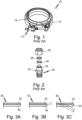
- Fig. 1 is a perspective view of a prior art pipe connector, in this case a clamp 10 that includes a compression band 12 (which can also be referred to generically as a connecting structure) that can be tightened with clamp mechanism 14.
- the compression band 12 is configured to fit over a hose or tube (not shown; but see Fig. 7 ) that is often inserted into a rigid shank (not shown) that forms a part of an adjacent hose, pipe, or tube, creating a joint (not shown) between the two adjacent sections of hose, pipe, or tube.
- compression band 12 is supplemented by a metallic or polymeric secondary compression band 14 that fits between the hose, tube or shank.
- the secondary compression band 14 may be a single piece or may comprise multiple (i.e., two or more) pieces.
- the materials used to make the clamp 10 should be selected to be compatible with the application for which the clamp 10 is intended.
- the size and construction of the compression band 12, secondary compression band 16, and clamp mechanism 14 should be selected to be compatible with the application for which the clamp 10 is intended.
- the depiction of the particular pipe connector (clamp 10) shown in Fig. 1 is not intended to limit the scope of this disclosure in any way. It is merely intended to illustrate one of many options well known in the art for constructing such a pipe connector. A person of ordinary skill knowledgeable about such pipe connectors will recognize that the pipe connectors that are the subject of this disclosure can encompass a wide range of pipe connector designs.
- Fig. 2 is an exploded view of another type of prior art pipe connector, a twin ferrule tube fitting 20 that includes a fitting body 22 with threads 24, a front ferule 26, a back ferule 28, and a threaded nut 30 (which can collectively be referred to generically as a connecting structure).
- the fitting body 22 and front ferule 24 slip onto a first section of hose, pipe, or tube (not shown; but see Fig. 7 ).
- the back ferule 26 and nut 28 slip onto a second section of hose, pipe, or tube (not shown).
- the threaded nut 30 engages the threads 24 of fitting body 22.
- Threaded nut 28 can be screwed onto the threads 24 of fitting body 22, compressing the front ferule 26 and back ferule 28 against the first section and second section, respectively, to form a seal between the first section and second section.
- the materials used to make the twin ferrule tube fitting 20 should be selected to be compatible with the application for which the twin ferrule tube fitting 20 is intended.
- the size and construction of the fitting body 22, front ferule 26, back ferule 28 and threaded nut 30 should be selected to be compatible with the application for which the twin ferrule tube fitting 20 is intended.
- the depiction of the particular pipe connector (twin ferrule tube fitting 20) shown in Fig. 2 is not intended to limit the scope of this disclosure in any way. It is merely intended to illustrate one of many options well known in the art for construction such a pipe connector. A person of ordinary skill knowledgeable about such pipe connectors will recognize that the pipe connectors that are the subject of this disclosure can encompass a wide range of pipe connector designs.
- Fig. 3A shows one embodiment of a thermally adaptive material that is within the scope of this disclosure--a two layer structure 30 having a first layer 32 and a second layer 34, each of which has a different coefficient of thermal expansion (CTE).
- the first layer 32 and the second layer 34 are configured such that the two layer structure 30 changes shape as a result of temperature changes associated with thermal cycling.
- the two layers 32, 34 can be made from two different materials (which can be metals, polymers, or any other material suitable for a particular application) that inherently have different CTEs or the same material with metallic, carbon, fibers (e.g., Kevlar fibers), or other additives that alter the material's CTE.
- thermally adaptive material may be manufactured using additive manufacturing techniques (e.g., 3D printing).
- additive manufacturing techniques e.g., 3D printing
- two layer structure 30 may, in fact, have more than two layers (e.g., three layers, four layers, or even more layers) as long as at least two layers have different CTEs.
- the term "two layer structure” is not limited to two layer.
- the term "two layer structure” encompasses structures having two layers, three layers, four layers, or any number of layers as long at least two of the layers have different CTEs.
- Fig. 3B shows the two layer structure 30 in which the first layer 32 has a CTE greater than the CTE of the second layer 34. If the two layers 32, 34 are allowed to deform independently, the first layer 32 grows in a lateral direction to a greater extent than second layer 34 as Fig. 3B shows. If the two layers 32, 34 are constrained to deform together, the two layer structure 30 deflects in the direction of the second layer 32 (shown in Fig. 3C ) because the CTE of the second layer 32 is less than the CTE of the first layer 32 (i.e., the first layer 32 grows in a lateral direction to a greater extent than second layer 34 causing deflection in the direction of the second layer 34).
- Figs. 4A-4C are schematics of pipe connectors 40 of the present disclosure having two ( Fig. 4A ), three ( Fig. 4B ), and four ( Fig. 4C ) sections 42 of a thermally adaptive material along hoop directions.
- the remaining sections 44 of the pipe connectors 40 may be made from any other material that is compatible with the thermally adaptive material section 42 and appropriate for a particular application. While Figs.
- each section 42 in a particular pipe connector 40 may be made from the same thermally adaptive material.
- one or more of sections 42 in a particular pipe connector 40 may be made from different thermally adaptive materials.
- the thermally adaptive materials used for pipe connectors 40 may be a two (or more) layer material similar to that described above and shown in Figs. 3A-3C . In other embodiments, the thermally adaptive materials used for pipe connectors 40 may be a material similar to that described below and shown in Figs. 6A-6B .
- the embodiments of pipe connectors 40 shown in Figs. 4A-4C are just schematics that can in practice be any configuration of pipe connector useful for a particular embodiment, including a clamp-type pipe connector similar to that shown in Fig. 1 .
- the pipe connectors 40 depicted in Figs. 4A-4C could be used as a compression band or secondary compression band of a clamp-style pipe connector similar to the clamp shown in Fig. 1 .
- the pipe connectors 40 shown schematically in Figs. 4A-4C can be one or more elements of a twin ferule tube fitting similar to that shown in Fig. 2 .
- FIG. 4A-4C could be used as any component, including the front ferrule or back ferrule of a twin ferrule tube fitting shown in Fig. 2 .
- a person of ordinary skill will recognize that the pipe connectors 40 shown schematically in Figs. 4A-4C can also be used for any other configuration of pipe connector useful for a particular embodiment.
- Figs. 5A-5D are schematics of pipe connectors 50 of the present disclosure having various shapes: circle ( Fig. 5A ), triangle ( Fig. 5B ), square ( Fig. 4C ) and hexagon (Fig. 4D).
- Each of the pipe connectors 50 include multiple sections 52 of a thermally adaptive material generally along hoop directions.
- the embodiments of pipe connectors 50 shown in Figs. 5A-5D include remaining sections 54 that may be made from any other material that is compatible with the thermally adaptive material section 52 and appropriate for a particular application. While Figs.
- FIGS. 5A-5D show embodiments of pipe connectors 50 including a certain number of sections 52 made from a thermally adaptive material, there is no limit to the number of such sections 52 or the size of each such section 52.
- the number and size of sections 52 made from a thermally adaptive material should be selected to be appropriate for a particular application.
- the specific thermally adaptive material used for each such section 52 should be selected to be appropriate for a particular application.
- each section 52 in a particular pipe connectors 50 may be made from the same thermally adaptive material.
- one or more of sections 52 in a particular pipe connector 50 may be made from different thermally adaptive materials.
- the thermally adaptive materials used for pipe connectors 50 may be a two (or more) layer material similar to that described above and shown in Figs. 3A-3C .
- the thermally adaptive materials used for pipe connectors 40 may be a material similar to that described below and shown in Figs. 6A-6B .
- the embodiments of pipe connectors 50 shown in Figs. 5A-5D are just schematics that can in practice be any configuration of pipe connector useful for a particular embodiment, including a clamp-type pipe connector similar to that shown in Fig. 1 .
- the pipe connectors 50 depicted in Figs. 5A-5D could be used as a compression band or secondary compression band of a clamp-style pipe connector similar to the clamp shown in Fig. 1 .
- the pipe connectors 50 shown schematically in Figs. 5A-5D can be one or more elements of a twin ferule tube fitting similar to that shown in Fig. 2 .
- 5A-5D could be used as any component, including the front ferrule or back ferrule of a twin ferrule tube fitting shown in Fig. 2 .
- a person of ordinary skill will recognize that the pipe connectors 50 shown schematically in Figs. 5A-5D can also be used for any other configuration of pipe connector useful for a particular embodiment.
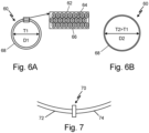
- Figs. 6A and 6B show another embodiment pipe connector 60 made from a different thermally adaptive material 62 than shown in Figs. 3A-3C .
- Fig. 6A shows pipe connector 60 in a first thermal state, which is a "cold” state (i.e., "cold” relative to the temperature it experiences during operation).
- the thermally adaptive material 62 from which pipe connector 60 is made includes a first material 64 having a first CTE dispersed in a matrix of a second material 66 having a second CTE.
- the first material 64 and second material 66 should be mutually insoluble such that they form distinct phases with distinct properties when formed into the thermally adaptive material 62.
- first material 64 and second material 66 may be an elastic/flexible material, such as a thermoplastic polymer or photopolymer. Both of the first material 64 and second material 66 may be polymers or one of the first material 64 and second material 66 may be a polymer and the other material may be a filler, such as an organic or inorganic phase.
- Suitable polymers include polyamides (PA), polystyrenes (PS), thermoplastic elastomers (TPE), polypropylene (PP), and polyaryletherketone (PAEK).
- Suitable organic or inorganic phases include carbon-based materials (including carbon nanotubes), silica, or any other suitable materials known in the art.
- the shape and distribution of the first material 64 in the second material 66 may be selected to cause the thermally adaptive material 62 to undergo a uniform shape change in all dimensions.
- pipe connector 60 made from such a thermally adaptive material 62 can change from a circular cross-section with a first diameter (D1) at in a first thermal (non-operating) state (T1) (as shown in Fig. 6A ) to a circular cross-section with a second diameter (D2) at in a second thermal (operating) state (T2) (as shown in Fig. 6B ), where T2 > T1 and D2 > D1.
- the shape change that pipe connector 60 undergoes between the first thermal state ( Fig. 6A ) and the second thermal state ( Fig. 6B ) is due to the thermally adaptive material 62 from which pipe connector 60 is made.
- the shape and distribution of the first material 64 in the second material 66 may be selected to cause the thermally adaptive material 62 to undergo a non-uniform shape change in selected dimensions.
- the distribution of the first material 64 in the second material 66 in portion of the pipe connector 60 e.g., the "top” and “bottom” of the pipe connector 60
- the distribution of the first material 64 in the second material 66 in different portion of the pipe connector 60 e.g., radially offset by a defined amount, such as 45°, 60°, 90° or any other amount from the "top” and "bottom” of the pipe connector 60
- a defined amount such as 45°, 60°, 90° or any other amount from the "top” and "bottom” of the pipe connector 60
- pipe connector 60 made from such a thermally adaptive material 62 with at least two different CTEs can change from a circular cross-section with a first diameter (D1) at in a first thermal (non-operating) state (T1) to a non-circular cross-section (e.g., "oval" shape) at in a second thermal (operating) state (T2).
- the shape change that pipe connector 60 undergoes between the first thermal state and the second thermal state is due to the thermally adaptive material 62 having at least two different CTEs from which pipe connector 60 is made.
- a similar approach varying the shape and distribution of the first material 64 in the second material 66 to create zones with different CTEs in a pipe connector 60 can be applied to any type of pipe connector 60 and any shape pipe connector 60, including but not limited to all of the shapes shown in Figs. 5A-5D .
- Fig. 7 shows a first section 72 of hose, pipe, or tube connected to a second section 74 of hose, pipe, or tube by a pipe connector 70 at a joint (not shown because it is "underneath" the pipe connector 70) between the first section 72 and second section 74.
- the pipe connector 70 of Fig. 7 is shown only as a schematic because the pipe connector 70 can be any of the pipe connectors 40, 50, 60 discussed above (including prior art pipe connectors 10 and 30) or any other configuration of pipe connector useful for a particular embodiment.
- thermally cycling pipe connector 70 between an operating state (the second thermal state) and a non-operating state (the first thermal state) results in an element (e.g., a connecting structure) of piping connector 70 forming a leak-free seal between a first section 72 of hose, pipe, or tube (not shown) and a second section 74 of hose pipe, or tube (not shown) that is positioned adjacent to the first section 72.
- an element e.g., a connecting structure
- the thermally adaptive materials discussed in this disclosure may be metallic or non-metallic materials suited for the intended application (e.g., having required structural and thermal properties).
- the pipe connectors and thermally adaptive materials described in this disclosure can be made from additive manufacturing, including 3-D printing (including multi-material 3-D printing), techniques that are well known. Of course, such pipe connectors and thermally adaptive materials can be made from any other manufacturing techniques that a person of ordinary skill would deem suitable for a particular application.
- a pipe connector such as a clamp or twin ferrule tube fitting, made from a thermally adaptive material as described in this disclosure provides numerous advantages. Incorporating thermally adaptive material into a piping connector used for an application with large temperature variations (e.g., cryogenic fluids or other applications than include large temperature variations) can improve safety by establishing a leak-free seal between adjacent sections of hose, pipe, or tube at a joint between the sections.
- large temperature variations e.g., cryogenic fluids or other applications than include large temperature variations
- An embodiment of a pipe connector includes a connecting structure configured to secure a first section of hose, pipe, or tube to an adjacent second section of hose, pipe, or tube positioned adjacent to the first section at a joint between the first section and the second section.
- the connecting structure includes at least one segment of a thermally adaptive material. The at least segment is configured to undergo a shape change as a result of thermal cycling such the shape change causes the connecting structure to form a leak-free seal between the first section and the second section at the j oint.
- the pipe connector of the preceding paragraph can optionally include, additionally and/or alternatively, any one or more of the following features, configurations, and/or additional components:
- thermally adaptive material comprises two layers, each of which has a different coefficient of thermal expansion.
- thermoly adaptive material comprises a first material having a first coefficient of thermal expansion dispersed in a matrix of a second material having a second coefficient of thermal expansion.
- connecting structure is configured as a clamp that slips over the j oint between the first section and second section to secure the first section to the second section when the thermally adaptive material undergoes a shape change as a result of thermal cycling.
- the connecting structure is configured as a twin ferrule tube fitting having a fitting body and a front ferrule configured to slip onto the first section and a back ferrule and a nut configured to slip onto the second section of hose, pipe, or tube, wherein the connecting structure is configured to secure the first section to the second section when the nut and fitting body are fastened to each other such that the front ferrule is compressed against the first section and the back ferrule is compressed against the second section.
- An embodiment of a clamp-type pipe connector includes a connecting structure configured to slip over a joint formed between a first section of hose, pipe, or tube and an adjacent second section of hose, pipe, or tube.
- the connecting structure includes at least one segment comprising a thermally adaptive material and the at least segment is configured to undergo a shape change in a hoop direction as a result of thermal cycling such that the shape change causes the connecting structure to form a leak-free seal between the first section and the second section.
- conduit of the preceding paragraph can optionally include, additionally and/or alternatively, any one or more of the following features, configurations, and/or additional components:
- thermoly adaptive material comprises two layers, each of which has a different coefficient of thermal expansion.
- thermoly adaptive material includes a first material having a first coefficient of thermal expansion dispersed in a matrix of a second material having a second coefficient of thermal expansion.
- An embodiment of a twin ferrule tube fitting including a connecting structure comprising a fitting body and a front ferrule configured to slip onto a first section first section of hose, pipe, or tube and a back ferrule and a nut configured to slip onto a second section of hose, pipe, or tube positioned adjacent to the first section forming a joint between the first section and the second section, wherein the connecting structure is configured to secure the first section to the second section when the nut and fitting body are fastened to each other such that the front ferrule is compressed against the first section and the back ferrule is compressed against the second section.
- At least one of the nut, fitting body, front ferrule and back ferrule comprises a thermally adaptive material that is configured to undergo a shape change in a hoop direction as a result of thermal cycling such that the shape change causes the connecting structure to form a leak-free seal between the first section and the second section.
- twin ferrule tube fitting of the preceding paragraph can optionally include, additionally and/or alternatively, any one or more of the following features, configurations, and/or additional components:
- thermoly adaptive material comprises two layers, each of which has a different coefficient of thermal expansion.
- thermoly adaptive material comprises a first material having a first coefficient of thermal expansion dispersed in a matrix of a second material having a second coefficient of thermal expansion.
Landscapes
- Engineering & Computer Science (AREA)
- General Engineering & Computer Science (AREA)
- Mechanical Engineering (AREA)
- Rigid Pipes And Flexible Pipes (AREA)
Abstract
A pipe connector (40)includes a connecting structure configured to secure a first section of hose, pipe, or tube (72) to an adjacent second section of hose, pipe, or tube (74) positioned adjacent to the first section at a joint between the first section and the second section. The connecting structure includes at least one segment of a thermally adaptive material. The at least one segment is configured to undergo a shape change as a result of thermal cycling such the shape change causes the connecting structure to form a leak-free seal between the first section and the second section at the joint.
Description
- The present disclosure relates generally to pipe connectors and in particular to pipe connectors used in variable thermal environments.
- Pipe connectors are routinely used to connect sections of hose, piping, or tubing to adjacent sections by applying a load, often a compression load, at a joint between adjacent sections of hose, piping, or tubing. When used in variable thermal environments, i.e., environments subject to significant changes in temperature, pipe connectors may thermally expand (or contract) as a result of the thermal expansion properties of which the pipe connectors are made. Such thermal expansion can cause the pipe connectors to lose the load required to maintain a secure connection between adjacent sections of hose, piping, or tubing.
- According to one aspect of the present invention, a pipe connector includes a connecting structure configured to secure a first section of hose, pipe, or tube to an adjacent second section of hose, pipe, or tube positioned adjacent to the first section at a joint between the first section and the second section. The connecting structure includes at least one segment of a thermally adaptive material. The at least one segment is configured to undergo a shape change as a result of thermal cycling such the shape change causes the connecting structure to form a leak-free seal between the first section and the second section at the joint.
- According to another aspect of the present invention, a clamp-type pipe connector includes a connecting structure configured to slip over a joint formed between a first section of hose, pipe, or tube and an adjacent second section of hose, pipe, or tube. The connecting structure includes at least one segment of a thermally adaptive material. The at least segment is configured to undergo a shape change in a hoop direction as a result of thermal cycling such that the shape change causes the connecting structure to form a leak-free seal between the first section and the second section.
- According to yet another aspect of the present invention, a twin ferrule tube fitting includes a connecting structure having a fitting body and a front ferrule configured to slip onto a first section first section of hose, pipe, or tube and a back ferrule and a nut configured to slip onto a second section of hose, pipe, or tube positioned adjacent to the first section forming a joint between the first section and the second section. The connecting structure is configured to secure the first section to the second section when the nut and fitting body are fastened to each other such that the front ferrule is compressed against the first section and the back ferrule is compressed against the second section. At least one of the nut, fitting body, front ferrule and back ferrule is made from a thermally adaptive material that is configured to undergo a shape change in a hoop direction as a result of thermal cycling such that the shape change causes the connecting structure to form a leak-free seal between the first section and the second section.
-
-
Fig. 1 is a perspective view of a prior art clamp. -
Fig. 2 is an exploded view of a prior art twin ferrule tube fitting. -
Fig. 3A is a two layer structure in which each layer has a different coefficient of thermal expansion. -
Fig. 3B is the two layer structure ofFig. 3A showing the layers deforming independently when thermally cycled. -
Fig. 3C is the two layer structure ofFig. 3A showing the layers deforming together when thermally cycled. -
Figs. 4A-4C are schematics of pipe connectors having two, three, and four sections made from a thermally adaptive material. -
Figs. 5A-5D are schematics of pipe connectors of various shapes having sections made from a thermally adaptive material. -
Fig. 6A shows another pipe connector made from a thermally adaptive material in a first thermal state. -
Fig. 6B shows the pipe connector ofFig. 6A in a second thermal state. -
Fig. 7 shows a first section of hose, pipe, or tube connected to a second section of hose, pipe, or tube by a pipe connector at a joint between the first section and second section. - Pipe connectors are routinely used to connect sections of hose, piping, or tubing to adjacent sections by applying a load, often a compression load, at a joint between adjacent sections of hose, piping, or tubing. Common types of pipe connectors include clamp-style pipe connectors and twin ferrule-type connectors. Many other types of pipe connectors are known in the art. One common challenge of prior art pipe connectors is that they tend to expand (or contract) when used in variable thermal environments, i.e., environments subject to significant changes in temperature. One such example of a variable thermal environment is one in which cryogenic materials are used. Such an environment features a dramatic difference between non-operating conditions (e.g., ordinary environmental ambient conditions) and operating conditions (e.g., very cold cryogenic conditions). The expansion characteristics of pipe connectors, which are a result of the thermal expansion properties of which the pipe connectors are made, may limit the applications for which they can be used because undesirable thermal expansion can cause the pipe connectors to lose the load required to maintain a secure connection between adjacent sections of hose, piping, or tubing.
- Making at least part of such a pipe connector from a thermally adaptive material can address the problem of loss of load required to maintain a secure connection between adjacent sections of hose, piping, or tubing. In the context of this disclosure a "thermally adaptive material" means a material that changes shape with thermal cycling (i.e., a change in temperature) to maintain clamping load in a variable thermal environment. As described further below, the thermally adaptive material can include two or more layers with different coefficients of thermal expansion (CTE) that deform differently with thermal cycling. Different CTEs may be achieved using two different material types (which can be metals, polymers, or any other material suitable for a particular application) that inherently have different CTEs or the same material with metallic, carbon, fibers (e.g., Kevlar fibers), of other additives that alter the material's CTE. Alternately, the thermally adaptive material can include a first material having a first CTE dispersed in a matrix of a second material having a second CTE. The thermally adaptive material may manufactured using additive manufacturing techniques (e.g., 3D printing). Other types of thermally adaptive materials also fall within the scope of this disclosure.
-
Fig. 1 is a perspective view of a prior art pipe connector, in this case aclamp 10 that includes a compression band 12 (which can also be referred to generically as a connecting structure) that can be tightened withclamp mechanism 14. Thecompression band 12 is configured to fit over a hose or tube (not shown; but seeFig. 7 ) that is often inserted into a rigid shank (not shown) that forms a part of an adjacent hose, pipe, or tube, creating a joint (not shown) between the two adjacent sections of hose, pipe, or tube. In someapplications compression band 12 is supplemented by a metallic or polymericsecondary compression band 14 that fits between the hose, tube or shank. Thesecondary compression band 14 may be a single piece or may comprise multiple (i.e., two or more) pieces. As is well known in the art, the materials used to make theclamp 10 should be selected to be compatible with the application for which theclamp 10 is intended. Similarly, the size and construction of thecompression band 12,secondary compression band 16, andclamp mechanism 14 should be selected to be compatible with the application for which theclamp 10 is intended. The depiction of the particular pipe connector (clamp 10) shown inFig. 1 is not intended to limit the scope of this disclosure in any way. It is merely intended to illustrate one of many options well known in the art for constructing such a pipe connector. A person of ordinary skill knowledgeable about such pipe connectors will recognize that the pipe connectors that are the subject of this disclosure can encompass a wide range of pipe connector designs. -
Fig. 2 is an exploded view of another type of prior art pipe connector, a twinferrule tube fitting 20 that includes afitting body 22 withthreads 24, afront ferule 26, aback ferule 28, and a threaded nut 30 (which can collectively be referred to generically as a connecting structure). As well known in the art, thefitting body 22 andfront ferule 24 slip onto a first section of hose, pipe, or tube (not shown; but seeFig. 7 ). Theback ferule 26 andnut 28 slip onto a second section of hose, pipe, or tube (not shown). When the first section of hose, pipe, or tube is positioned adjected to the second section of hose, pipe, or tube, forming a joint between the first section and second section, the threadednut 30 engages thethreads 24 offitting body 22. Threadednut 28 can be screwed onto thethreads 24 offitting body 22, compressing thefront ferule 26 and back ferule 28 against the first section and second section, respectively, to form a seal between the first section and second section. As is well known in the art, the materials used to make the twin ferrule tube fitting 20 should be selected to be compatible with the application for which the twin ferrule tube fitting 20 is intended. Similarly, the size and construction of thefitting body 22,front ferule 26, back ferule 28 and threadednut 30 should be selected to be compatible with the application for which the twin ferrule tube fitting 20 is intended. The depiction of the particular pipe connector (twin ferrule tube fitting 20) shown inFig. 2 is not intended to limit the scope of this disclosure in any way. It is merely intended to illustrate one of many options well known in the art for construction such a pipe connector. A person of ordinary skill knowledgeable about such pipe connectors will recognize that the pipe connectors that are the subject of this disclosure can encompass a wide range of pipe connector designs. -
Fig. 3A shows one embodiment of a thermally adaptive material that is within the scope of this disclosure--a twolayer structure 30 having afirst layer 32 and asecond layer 34, each of which has a different coefficient of thermal expansion (CTE). As discussed further below, thefirst layer 32 and thesecond layer 34 are configured such that the twolayer structure 30 changes shape as a result of temperature changes associated with thermal cycling. As discussed above, the twolayers layer structure 30 may, in fact, have more than two layers (e.g., three layers, four layers, or even more layers) as long as at least two layers have different CTEs. Accordingly, in the context of this disclosure, the term "two layer structure" is not limited to two layer. The term "two layer structure" encompasses structures having two layers, three layers, four layers, or any number of layers as long at least two of the layers have different CTEs. -
Fig. 3B shows the twolayer structure 30 in which thefirst layer 32 has a CTE greater than the CTE of thesecond layer 34. If the twolayers first layer 32 grows in a lateral direction to a greater extent thansecond layer 34 asFig. 3B shows. If the twolayers layer structure 30 deflects in the direction of the second layer 32 (shown inFig. 3C ) because the CTE of thesecond layer 32 is less than the CTE of the first layer 32 (i.e., thefirst layer 32 grows in a lateral direction to a greater extent thansecond layer 34 causing deflection in the direction of the second layer 34). - As discussed above, we propose making at least part of a pipe connector from a thermally adaptive material, including a thermally adaptive material similar to that shown in
Figs. 3A-3C .Figs. 4A-4C are schematics ofpipe connectors 40 of the present disclosure having two (Fig. 4A ), three (Fig. 4B ), and four (Fig. 4C )sections 42 of a thermally adaptive material along hoop directions. The remainingsections 44 of thepipe connectors 40 may be made from any other material that is compatible with the thermallyadaptive material section 42 and appropriate for a particular application. WhileFigs. 4A-4C show embodiments ofpipe connectors 40 including a certain number ofsections 42 made from a thermally adaptive material, there is no limit to the number ofsuch sections 42 or the size of eachsuch section 42. The number and size ofsections 42 made from a thermally adaptive material should be selected to be appropriate for a particular application. Similarly the specific thermally adaptive material used for eachsuch section 42 should be selected to be appropriate for a particular application. In some embodiments, eachsection 42 in aparticular pipe connector 40 may be made from the same thermally adaptive material. Alternately, one or more ofsections 42 in aparticular pipe connector 40 may be made from different thermally adaptive materials. The thermally adaptive materials used forpipe connectors 40 may be a two (or more) layer material similar to that described above and shown inFigs. 3A-3C . In other embodiments, the thermally adaptive materials used forpipe connectors 40 may be a material similar to that described below and shown inFigs. 6A-6B . - The embodiments of
pipe connectors 40 shown inFigs. 4A-4C are just schematics that can in practice be any configuration of pipe connector useful for a particular embodiment, including a clamp-type pipe connector similar to that shown inFig. 1 . For example, thepipe connectors 40 depicted inFigs. 4A-4C could be used as a compression band or secondary compression band of a clamp-style pipe connector similar to the clamp shown inFig. 1 . In other embodiments thepipe connectors 40 shown schematically inFigs. 4A-4C can be one or more elements of a twin ferule tube fitting similar to that shown inFig. 2 . For example, thepipe connectors 40 depicted inFigs. 4A-4C could be used as any component, including the front ferrule or back ferrule of a twin ferrule tube fitting shown inFig. 2 . A person of ordinary skill will recognize that thepipe connectors 40 shown schematically inFigs. 4A-4C can also be used for any other configuration of pipe connector useful for a particular embodiment. -
Figs. 5A-5D are schematics ofpipe connectors 50 of the present disclosure having various shapes: circle (Fig. 5A ), triangle (Fig. 5B ), square (Fig. 4C ) and hexagon (Fig. 4D). Each of thepipe connectors 50 includemultiple sections 52 of a thermally adaptive material generally along hoop directions. As with the embodiments ofpipe connectors 40 shown inFigs. 4A-4C , the embodiments ofpipe connectors 50 shown inFigs. 5A-5D include remainingsections 54 that may be made from any other material that is compatible with the thermallyadaptive material section 52 and appropriate for a particular application. WhileFigs. 5A-5D show embodiments ofpipe connectors 50 including a certain number ofsections 52 made from a thermally adaptive material, there is no limit to the number ofsuch sections 52 or the size of eachsuch section 52. The number and size ofsections 52 made from a thermally adaptive material should be selected to be appropriate for a particular application. Similarly the specific thermally adaptive material used for eachsuch section 52 should be selected to be appropriate for a particular application. In some embodiments, eachsection 52 in aparticular pipe connectors 50 may be made from the same thermally adaptive material. Alternately, one or more ofsections 52 in aparticular pipe connector 50 may be made from different thermally adaptive materials. The thermally adaptive materials used forpipe connectors 50 may be a two (or more) layer material similar to that described above and shown inFigs. 3A-3C . In other embodiments, the thermally adaptive materials used forpipe connectors 40 may be a material similar to that described below and shown inFigs. 6A-6B . - The embodiments of
pipe connectors 50 shown inFigs. 5A-5D are just schematics that can in practice be any configuration of pipe connector useful for a particular embodiment, including a clamp-type pipe connector similar to that shown inFig. 1 . For example, thepipe connectors 50 depicted inFigs. 5A-5D could be used as a compression band or secondary compression band of a clamp-style pipe connector similar to the clamp shown inFig. 1 . In other embodiments thepipe connectors 50 shown schematically inFigs. 5A-5D can be one or more elements of a twin ferule tube fitting similar to that shown inFig. 2 . For example, thepipe connectors 50 depicted inFigs. 5A-5D could be used as any component, including the front ferrule or back ferrule of a twin ferrule tube fitting shown inFig. 2 . A person of ordinary skill will recognize that thepipe connectors 50 shown schematically inFigs. 5A-5D can also be used for any other configuration of pipe connector useful for a particular embodiment. -
Figs. 6A and 6B show anotherembodiment pipe connector 60 made from a different thermallyadaptive material 62 than shown inFigs. 3A-3C .Fig. 6A showspipe connector 60 in a first thermal state, which is a "cold" state (i.e., "cold" relative to the temperature it experiences during operation). The thermallyadaptive material 62 from whichpipe connector 60 is made includes afirst material 64 having a first CTE dispersed in a matrix of asecond material 66 having a second CTE. Thefirst material 64 andsecond material 66 should be mutually insoluble such that they form distinct phases with distinct properties when formed into the thermallyadaptive material 62. For example, at least one of thefirst material 64 andsecond material 66 may be an elastic/flexible material, such as a thermoplastic polymer or photopolymer. Both of thefirst material 64 andsecond material 66 may be polymers or one of thefirst material 64 andsecond material 66 may be a polymer and the other material may be a filler, such as an organic or inorganic phase. Suitable polymers include polyamides (PA), polystyrenes (PS), thermoplastic elastomers (TPE), polypropylene (PP), and polyaryletherketone (PAEK). Suitable organic or inorganic phases include carbon-based materials (including carbon nanotubes), silica, or any other suitable materials known in the art. The shape and distribution of thefirst material 64 in thesecond material 66 may be selected to cause the thermallyadaptive material 62 to undergo a uniform shape change in all dimensions. As a result,pipe connector 60 made from such a thermallyadaptive material 62 can change from a circular cross-section with a first diameter (D1) at in a first thermal (non-operating) state (T1) (as shown inFig. 6A ) to a circular cross-section with a second diameter (D2) at in a second thermal (operating) state (T2) (as shown inFig. 6B ), where T2 > T1 and D2 > D1. The shape change thatpipe connector 60 undergoes between the first thermal state (Fig. 6A ) and the second thermal state (Fig. 6B ) is due to the thermallyadaptive material 62 from whichpipe connector 60 is made. - Alternately, the shape and distribution of the
first material 64 in thesecond material 66 may be selected to cause the thermallyadaptive material 62 to undergo a non-uniform shape change in selected dimensions. For example, the distribution of thefirst material 64 in thesecond material 66 in portion of the pipe connector 60 (e.g., the "top" and "bottom" of the pipe connector 60) can be selected to create a first CTE and the distribution of thefirst material 64 in thesecond material 66 in different portion of the pipe connector 60 (e.g., radially offset by a defined amount, such as 45°, 60°, 90° or any other amount from the "top" and "bottom" of the pipe connector 60) can be selected to create a different second CTE. As a result,pipe connector 60 made from such a thermallyadaptive material 62 with at least two different CTEs can change from a circular cross-section with a first diameter (D1) at in a first thermal (non-operating) state (T1) to a non-circular cross-section (e.g., "oval" shape) at in a second thermal (operating) state (T2). The shape change thatpipe connector 60 undergoes between the first thermal state and the second thermal state is due to the thermallyadaptive material 62 having at least two different CTEs from whichpipe connector 60 is made. A similar approach varying the shape and distribution of thefirst material 64 in thesecond material 66 to create zones with different CTEs in apipe connector 60 can be applied to any type ofpipe connector 60 and anyshape pipe connector 60, including but not limited to all of the shapes shown inFigs. 5A-5D . -
Fig. 7 shows afirst section 72 of hose, pipe, or tube connected to asecond section 74 of hose, pipe, or tube by apipe connector 70 at a joint (not shown because it is "underneath" the pipe connector 70) between thefirst section 72 andsecond section 74. Thepipe connector 70 ofFig. 7 is shown only as a schematic because thepipe connector 70 can be any of thepipe connectors art pipe connectors 10 and 30) or any other configuration of pipe connector useful for a particular embodiment. In all embodiments, thermallycycling pipe connector 70 between an operating state (the second thermal state) and a non-operating state (the first thermal state) results in an element (e.g., a connecting structure) ofpiping connector 70 forming a leak-free seal between afirst section 72 of hose, pipe, or tube (not shown) and asecond section 74 of hose pipe, or tube (not shown) that is positioned adjacent to thefirst section 72. - The thermally adaptive materials discussed in this disclosure may be metallic or non-metallic materials suited for the intended application (e.g., having required structural and thermal properties). The pipe connectors and thermally adaptive materials described in this disclosure can be made from additive manufacturing, including 3-D printing (including multi-material 3-D printing), techniques that are well known. Of course, such pipe connectors and thermally adaptive materials can be made from any other manufacturing techniques that a person of ordinary skill would deem suitable for a particular application.
- A pipe connector, such as a clamp or twin ferrule tube fitting, made from a thermally adaptive material as described in this disclosure provides numerous advantages. Incorporating thermally adaptive material into a piping connector used for an application with large temperature variations (e.g., cryogenic fluids or other applications than include large temperature variations) can improve safety by establishing a leak-free seal between adjacent sections of hose, pipe, or tube at a joint between the sections.
- The following are non-exclusive descriptions of possible embodiments of the present invention.
- An embodiment of a pipe connector includes a connecting structure configured to secure a first section of hose, pipe, or tube to an adjacent second section of hose, pipe, or tube positioned adjacent to the first section at a joint between the first section and the second section. The connecting structure includes at least one segment of a thermally adaptive material. The at least segment is configured to undergo a shape change as a result of thermal cycling such the shape change causes the connecting structure to form a leak-free seal between the first section and the second section at the j oint.
- The pipe connector of the preceding paragraph can optionally include, additionally and/or alternatively, any one or more of the following features, configurations, and/or additional components:
- An embodiment in which the thermally adaptive material comprises two layers, each of which has a different coefficient of thermal expansion.
- An embodiment of the preceding paragraph in which the connecting structure is configured to undergo a shape change in a hoop direction as a result of thermal cycling.
- An embodiment of paragraph [0033] in which the thermally adaptive material comprises a first material having a first coefficient of thermal expansion dispersed in a matrix of a second material having a second coefficient of thermal expansion.
- An embodiment of the preceding paragraph in which the connecting structure is configured to undergo a shape change in a hoop direction as a result of thermal cycling.
- An embodiment of any preceding paragraph in which the connecting structure is configured as a clamp that slips over the j oint between the first section and second section to secure the first section to the second section when the thermally adaptive material undergoes a shape change as a result of thermal cycling.
- An embodiment of any preceding paragraph in which the connecting structure is configured as a twin ferrule tube fitting having a fitting body and a front ferrule configured to slip onto the first section and a back ferrule and a nut configured to slip onto the second section of hose, pipe, or tube, wherein the connecting structure is configured to secure the first section to the second section when the nut and fitting body are fastened to each other such that the front ferrule is compressed against the first section and the back ferrule is compressed against the second section.
- An embodiment of a clamp-type pipe connector includes a connecting structure configured to slip over a joint formed between a first section of hose, pipe, or tube and an adjacent second section of hose, pipe, or tube. The connecting structure includes at least one segment comprising a thermally adaptive material and the at least segment is configured to undergo a shape change in a hoop direction as a result of thermal cycling such that the shape change causes the connecting structure to form a leak-free seal between the first section and the second section.
- The conduit of the preceding paragraph can optionally include, additionally and/or alternatively, any one or more of the following features, configurations, and/or additional components:
- An embodiment of the clamp-type pipe connector in which the thermally adaptive material comprises two layers, each of which has a different coefficient of thermal expansion.
- An embodiment of the clamp-type pipe connector in which the thermally adaptive material includes a first material having a first coefficient of thermal expansion dispersed in a matrix of a second material having a second coefficient of thermal expansion.
- An embodiment of a twin ferrule tube fitting, including a connecting structure comprising a fitting body and a front ferrule configured to slip onto a first section first section of hose, pipe, or tube and a back ferrule and a nut configured to slip onto a second section of hose, pipe, or tube positioned adjacent to the first section forming a joint between the first section and the second section, wherein the connecting structure is configured to secure the first section to the second section when the nut and fitting body are fastened to each other such that the front ferrule is compressed against the first section and the back ferrule is compressed against the second section. At least one of the nut, fitting body, front ferrule and back ferrule comprises a thermally adaptive material that is configured to undergo a shape change in a hoop direction as a result of thermal cycling such that the shape change causes the connecting structure to form a leak-free seal between the first section and the second section.
- The twin ferrule tube fitting of the preceding paragraph can optionally include, additionally and/or alternatively, any one or more of the following features, configurations, and/or additional components:
- An embodiment of the twin ferrule tube fitting in which the thermally adaptive material comprises two layers, each of which has a different coefficient of thermal expansion.
- An embodiment of twin ferrule tube fitting in which the thermally adaptive material comprises a first material having a first coefficient of thermal expansion dispersed in a matrix of a second material having a second coefficient of thermal expansion.
- While the invention has been described and shown with reference to an exemplary embodiment(s), it will be understood by those skilled in the art that various changes may be made and equivalents may be substituted for elements thereof without departing from the scope of the invention. In addition, many modifications may be made to adapt a particular situation or material to the teachings of the invention without departing from the essential scope thereof. Therefore, it is intended that the invention not be limited to the particular embodiment(s) disclosed, but that the invention will include all embodiments falling within the scope of the appended claims.
Claims (13)
- A pipe connector, comprising:a connecting structure configured to secure a first section of hose, pipe, or tube to an adjacent second section of hose, pipe, or tube positioned adjacent to the first section at a joint between the first section and the second section;wherein the connecting structure includes at least one segment comprising a thermally adaptive material and the at least segment is configured to undergo a shape change as a result of thermal cycling such the shape change causes the connecting structure to form a leak-free seal between the first section and the second section at the joint.
- The pipe connector of claim 1, wherein the thermally adaptive material comprises two layers, each of which has a different coefficient of thermal expansion.
- The pipe connector of claim 2, wherein the connecting structure is configured to undergo a shape change in a hoop direction as a result of thermal cycling.
- The pipe connector of claim 1 or 2, wherein the thermally adaptive material comprises a first material having a first coefficient of thermal expansion dispersed in a matrix of a second material having a second coefficient of thermal expansion.
- The pipe connector of claim 4, wherein the connecting structure is configured to undergo a shape change in a hoop direction as a result of thermal cycling.
- The pipe connector of any preceding claim, wherein the connecting structure is configured as a clamp that slips over the j oint between the first section and second section to secure the first section to the second section when the thermally adaptive material undergoes a shape change as a result of thermal cycling.
- The pipe connector of any preceding claim, wherein the connecting structure is configured as a twin ferrule tube fitting having a fitting body and a front ferrule configured to slip onto the first section and a back ferrule and a nut configured to slip onto the second section of hose, pipe, or tube, wherein the connecting structure is configured to secure the first section to the second section when the nut and fitting body are fastened to each other such that the front ferrule is compressed against the first section and the back ferrule is compressed against the second section.
- A clamp-type pipe connector, comprising:a connecting structure configured to slip over a joint formed between a first section of hose, pipe, or tube and an adjacent second section of hose, pipe, or tube;wherein the connecting structure includes at least one segment comprising a thermally adaptive material and the at least segment is configured to undergo a shape change in a hoop direction as a result of thermal cycling such that the shape change causes the connecting structure to form a leak-free seal between the first section and the second section.
- The clamp-type pipe connector of claim 8, wherein the thermally adaptive material comprises two layers, each of which has a different coefficient of thermal expansion.
- The clamp-type pipe connector of claim 8 or 9, wherein the thermally adaptive material comprises a first material having a first coefficient of thermal expansion dispersed in a matrix of a second material having a second coefficient of thermal expansion.
- A twin ferrule tube fitting, comprising:a connecting structure comprising a fitting body and a front ferrule configured to slip onto a first section first section of hose, pipe, or tube and a back ferrule and a nut configured to slip onto a second section of hose, pipe, or tube positioned adjacent to the first section forming a joint between the first section and the second section, wherein the connecting structure is configured to secure the first section to the second section when the nut and fitting body are fastened to each other such that the front ferrule is compressed against the first section and the back ferrule is compressed against the second section;wherein at least one of the nut, fitting body, front ferrule and back ferrule comprises a thermally adaptive material that is configured to undergo a shape change in a hoop direction as a result of thermal cycling such that the shape change causes the connecting structure to form a leak-free seal between the first section and the second section.
- The twin ferrule tube fitting of claim 11, wherein the thermally adaptive material comprises two layers, each of which has a different coefficient of thermal expansion.
- The twin ferrule tube fitting of claim 11 or 12, wherein the thermally adaptive material comprises a first material having a first coefficient of thermal expansion dispersed in a matrix of a second material having a second coefficient of thermal expansion.
Applications Claiming Priority (1)
| Application Number | Priority Date | Filing Date | Title |
|---|---|---|---|
| US18/169,534 US20240271727A1 (en) | 2023-02-15 | 2023-02-15 | Thermally adaptive pipe connectors |
Publications (1)
| Publication Number | Publication Date |
|---|---|
| EP4417851A1 true EP4417851A1 (en) | 2024-08-21 |
Family
ID=89854612
Family Applications (1)
| Application Number | Title | Priority Date | Filing Date |
|---|---|---|---|
| EP24156418.6A Pending EP4417851A1 (en) | 2023-02-15 | 2024-02-07 | Thermally adaptive pipe connectors |
Country Status (2)
| Country | Link |
|---|---|
| US (1) | US20240271727A1 (en) |
| EP (1) | EP4417851A1 (en) |
Families Citing this family (4)
| Publication number | Priority date | Publication date | Assignee | Title |
|---|---|---|---|---|
| US12523321B2 (en) * | 2021-04-06 | 2026-01-13 | Aero-Stream LLC | Riser and ingress device assembly for septic tank system |
| US12571421B2 (en) | 2023-02-01 | 2026-03-10 | Hamilton Sundstrand Corporation | Metal plated additively manufactured plastic shafts and their method of manufacturing |
| US12179425B2 (en) | 2023-02-01 | 2024-12-31 | Hamilton Sundstrand Corporation | Metal plated additively manufactured plastic rotor shrouds and their method of manufacturing |
| US12421859B2 (en) * | 2023-02-01 | 2025-09-23 | Hamilton Sundstrand Corporation | Metal plated additively manufactured plastic seal plates and their method of manufacturing |
Citations (3)
| Publication number | Priority date | Publication date | Assignee | Title |
|---|---|---|---|---|
| US20090272855A1 (en) * | 2008-05-02 | 2009-11-05 | Balmoral Comtec Limited | Device |
| AU2009294631B2 (en) * | 2008-09-16 | 2016-01-07 | Viega Technology Gmbh & Co. Kg | Two-part composite fitting |
| US20210324984A1 (en) * | 2020-04-17 | 2021-10-21 | Entegris, Inc. | Electrostatic discharge mitigation device |
Family Cites Families (2)
| Publication number | Priority date | Publication date | Assignee | Title |
|---|---|---|---|---|
| DE19800283C1 (en) * | 1998-01-07 | 1999-07-15 | Rasmussen Gmbh | Profile clamp and process for its manufacture |
| TW201237296A (en) * | 2010-12-09 | 2012-09-16 | Lubrizol Advanced Mat Inc | Fluid handling assembly having a multilayered composite pipe employing a mechanical coupling and method of assembling the fluid handling assembly |
-
2023
- 2023-02-15 US US18/169,534 patent/US20240271727A1/en not_active Abandoned
-
2024
- 2024-02-07 EP EP24156418.6A patent/EP4417851A1/en active Pending
Patent Citations (3)
| Publication number | Priority date | Publication date | Assignee | Title |
|---|---|---|---|---|
| US20090272855A1 (en) * | 2008-05-02 | 2009-11-05 | Balmoral Comtec Limited | Device |
| AU2009294631B2 (en) * | 2008-09-16 | 2016-01-07 | Viega Technology Gmbh & Co. Kg | Two-part composite fitting |
| US20210324984A1 (en) * | 2020-04-17 | 2021-10-21 | Entegris, Inc. | Electrostatic discharge mitigation device |
Also Published As
| Publication number | Publication date |
|---|---|
| US20240271727A1 (en) | 2024-08-15 |
Similar Documents
| Publication | Publication Date | Title |
|---|---|---|
| US20240271727A1 (en) | Thermally adaptive pipe connectors | |
| CN106030179B (en) | Connection system for PEX tubing to be connected with the accessory including fixture | |
| AU2011341622B2 (en) | Electrically conductive bushing connection to structure for current path | |
| JP7809473B2 (en) | Holder for cable conduit | |
| CN103379938B (en) | Separate type coupling assembly | |
| CA2566697A1 (en) | Mechanical pipe coupling having spacers | |
| JPS61175306A (en) | Method of connecting element to end section of pipe | |
| JP6951475B2 (en) | Coupling with seal that involves retracting the central leg | |
| JPH024838B2 (en) | ||
| CN102483189B (en) | Joining device for conduits and associated joining process | |
| US20150198278A1 (en) | Tube fitting | |
| WO2012162455A1 (en) | Multilayer annular clamp | |
| CA2897839A1 (en) | Quick fitting connector | |
| WO2022060646A1 (en) | Assemblies for reducing passive intermodulation in telecommunications structures | |
| CA1172283A (en) | Hose and tube fitting | |
| EP2894382B1 (en) | Tube fitting | |
| WO1997003811A1 (en) | Pipe joint | |
| CN1717562A (en) | Hydraulic hose fitting and method | |
| US20160141855A1 (en) | Strain Relief Device for a Harness or Cable | |
| US2396078A (en) | Pipe coupling | |
| US9765911B2 (en) | Soil pipe coupler | |
| EP2615351B1 (en) | Cold insulation device | |
| EP3255331B1 (en) | A method of connecting two conduits of equipment to be sterilised | |
| US20140299721A1 (en) | Hose Clamp Brace | |
| CN213685765U (en) | A variable inner diameter hydraulic pipe joint |
Legal Events
| Date | Code | Title | Description |
|---|---|---|---|
| PUAI | Public reference made under article 153(3) epc to a published international application that has entered the european phase |
Free format text: ORIGINAL CODE: 0009012 |
|
| STAA | Information on the status of an ep patent application or granted ep patent |
Free format text: STATUS: THE APPLICATION HAS BEEN PUBLISHED |
|
| AK | Designated contracting states |
Kind code of ref document: A1 Designated state(s): AL AT BE BG CH CY CZ DE DK EE ES FI FR GB GR HR HU IE IS IT LI LT LU LV MC ME MK MT NL NO PL PT RO RS SE SI SK SM TR |
|
| STAA | Information on the status of an ep patent application or granted ep patent |
Free format text: STATUS: REQUEST FOR EXAMINATION WAS MADE |
|
| 17P | Request for examination filed |
Effective date: 20250218 |