EP4417814A1 - Compressor and design method for same - Google Patents
Compressor and design method for same Download PDFInfo
- Publication number
- EP4417814A1 EP4417814A1 EP23819691.9A EP23819691A EP4417814A1 EP 4417814 A1 EP4417814 A1 EP 4417814A1 EP 23819691 A EP23819691 A EP 23819691A EP 4417814 A1 EP4417814 A1 EP 4417814A1
- Authority
- EP
- European Patent Office
- Prior art keywords
- compressor
- main body
- accumulator
- refrigerant
- compressor main
- Prior art date
- Legal status (The legal status is an assumption and is not a legal conclusion. Google has not performed a legal analysis and makes no representation as to the accuracy of the status listed.)
- Pending
Links
Images



Classifications
-
- F—MECHANICAL ENGINEERING; LIGHTING; HEATING; WEAPONS; BLASTING
- F04—POSITIVE - DISPLACEMENT MACHINES FOR LIQUIDS; PUMPS FOR LIQUIDS OR ELASTIC FLUIDS
- F04B—POSITIVE-DISPLACEMENT MACHINES FOR LIQUIDS; PUMPS
- F04B39/00—Component parts, details, or accessories, of pumps or pumping systems specially adapted for elastic fluids, not otherwise provided for in, or of interest apart from, groups F04B25/00 - F04B37/00
-
- F—MECHANICAL ENGINEERING; LIGHTING; HEATING; WEAPONS; BLASTING
- F01—MACHINES OR ENGINES IN GENERAL; ENGINE PLANTS IN GENERAL; STEAM ENGINES
- F01C—ROTARY-PISTON OR OSCILLATING-PISTON MACHINES OR ENGINES
- F01C21/00—Component parts, details or accessories not provided for in groups F01C1/00 - F01C20/00
- F01C21/10—Outer members for co-operation with rotary pistons; Casings
-
- F—MECHANICAL ENGINEERING; LIGHTING; HEATING; WEAPONS; BLASTING
- F04—POSITIVE - DISPLACEMENT MACHINES FOR LIQUIDS; PUMPS FOR LIQUIDS OR ELASTIC FLUIDS
- F04B—POSITIVE-DISPLACEMENT MACHINES FOR LIQUIDS; PUMPS
- F04B41/00—Pumping installations or systems specially adapted for elastic fluids
- F04B41/02—Pumping installations or systems specially adapted for elastic fluids having reservoirs
-
- F—MECHANICAL ENGINEERING; LIGHTING; HEATING; WEAPONS; BLASTING
- F04—POSITIVE - DISPLACEMENT MACHINES FOR LIQUIDS; PUMPS FOR LIQUIDS OR ELASTIC FLUIDS
- F04C—ROTARY-PISTON, OR OSCILLATING-PISTON, POSITIVE-DISPLACEMENT MACHINES FOR LIQUIDS; ROTARY-PISTON, OR OSCILLATING-PISTON, POSITIVE-DISPLACEMENT PUMPS
- F04C18/00—Rotary-piston pumps specially adapted for elastic fluids
- F04C18/30—Rotary-piston pumps specially adapted for elastic fluids having the characteristics covered by two or more of groups F04C18/02, F04C18/08, F04C18/22, F04C18/24, F04C18/48, or having the characteristics covered by one of these groups together with some other type of movement between co-operating members
- F04C18/34—Rotary-piston pumps specially adapted for elastic fluids having the characteristics covered by two or more of groups F04C18/02, F04C18/08, F04C18/22, F04C18/24, F04C18/48, or having the characteristics covered by one of these groups together with some other type of movement between co-operating members having the movement defined in group F04C18/08 or F04C18/22 and relative reciprocation between the co-operating members
- F04C18/356—Rotary-piston pumps specially adapted for elastic fluids having the characteristics covered by two or more of groups F04C18/02, F04C18/08, F04C18/22, F04C18/24, F04C18/48, or having the characteristics covered by one of these groups together with some other type of movement between co-operating members having the movement defined in group F04C18/08 or F04C18/22 and relative reciprocation between the co-operating members with vanes reciprocating with respect to the outer member
-
- F—MECHANICAL ENGINEERING; LIGHTING; HEATING; WEAPONS; BLASTING
- F04—POSITIVE - DISPLACEMENT MACHINES FOR LIQUIDS; PUMPS FOR LIQUIDS OR ELASTIC FLUIDS
- F04C—ROTARY-PISTON, OR OSCILLATING-PISTON, POSITIVE-DISPLACEMENT MACHINES FOR LIQUIDS; ROTARY-PISTON, OR OSCILLATING-PISTON, POSITIVE-DISPLACEMENT PUMPS
- F04C23/00—Combinations of two or more pumps, each being of rotary-piston or oscillating-piston type, specially adapted for elastic fluids; Pumping installations specially adapted for elastic fluids; Multi-stage pumps specially adapted for elastic fluids
- F04C23/008—Hermetic pumps
-
- F—MECHANICAL ENGINEERING; LIGHTING; HEATING; WEAPONS; BLASTING
- F04—POSITIVE - DISPLACEMENT MACHINES FOR LIQUIDS; PUMPS FOR LIQUIDS OR ELASTIC FLUIDS
- F04B—POSITIVE-DISPLACEMENT MACHINES FOR LIQUIDS; PUMPS
- F04B35/00—Piston pumps specially adapted for elastic fluids and characterised by the driving means to their working members, or by combination with, or adaptation to, specific driving engines or motors, not otherwise provided for
- F04B35/04—Piston pumps specially adapted for elastic fluids and characterised by the driving means to their working members, or by combination with, or adaptation to, specific driving engines or motors, not otherwise provided for the means being electric
-
- F—MECHANICAL ENGINEERING; LIGHTING; HEATING; WEAPONS; BLASTING
- F04—POSITIVE - DISPLACEMENT MACHINES FOR LIQUIDS; PUMPS FOR LIQUIDS OR ELASTIC FLUIDS
- F04C—ROTARY-PISTON, OR OSCILLATING-PISTON, POSITIVE-DISPLACEMENT MACHINES FOR LIQUIDS; ROTARY-PISTON, OR OSCILLATING-PISTON, POSITIVE-DISPLACEMENT PUMPS
- F04C2240/00—Components
- F04C2240/80—Other components
- F04C2240/804—Accumulators for refrigerant circuits
-
- F—MECHANICAL ENGINEERING; LIGHTING; HEATING; WEAPONS; BLASTING
- F04—POSITIVE - DISPLACEMENT MACHINES FOR LIQUIDS; PUMPS FOR LIQUIDS OR ELASTIC FLUIDS
- F04C—ROTARY-PISTON, OR OSCILLATING-PISTON, POSITIVE-DISPLACEMENT MACHINES FOR LIQUIDS; ROTARY-PISTON, OR OSCILLATING-PISTON, POSITIVE-DISPLACEMENT PUMPS
- F04C2250/00—Geometry
Definitions
- the present disclosure relates to a compressor and a method for designing the compressor.
- a rotary compressor is known as one of compressors used in refrigeration devices, air-conditioning devices, and the like.
- Patent Document 1 JP 2011-185123 A
- a related-art rotary compressor having a relatively large weight
- the moment of inertia of a static system is large, and thus vibration caused by driving of a rotary compression unit (for example, rotation of a piston rotor), which is a rotating system, tends to be suppressed.
- a rotary compression unit for example, rotation of a piston rotor
- the moment of inertia of the static system may decrease and a problem related to vibration may become apparent.
- the present disclosure has been made in view of such circumstances, and an object thereof is to provide a compressor capable of reducing vibration even when a compressor main body is miniaturized and a method for designing the compressor.
- a compressor (1) is a compressor including a compressor main body (10) including, in a tubular housing (2), a compression unit (6) compressing a refrigerant, and a tubular accumulator (12) coupled to a refrigerant suction portion of the compressor main body, in which 3 ⁇ (m1/D1)/(m2/D2) ⁇ 7, where m1 is a mass of the compressor main body, m2 is a mass of the accumulator, D1 is an outside diameter of the compressor main body, and D2 is an outside diameter of the accumulator.
- a method for designing a compressor according to another aspect of the present disclosure is a method for designing a compressor, the compressor including a compressor main body including, in a tubular housing, a compression unit compressing a refrigerant, and a tubular accumulator coupled to a refrigerant suction portion of the compressor main body, in which 3 ⁇ (m1/D1)/(m2/D2) ⁇ 7, where m1 is a mass of the compressor main body, m2 is a mass of the accumulator, D1 is an outside diameter of the compressor main body, and D2 is an outside diameter of the accumulator.
- a rotary compressor (hereinafter simply referred to as a "compressor") 1 according to the present embodiment is a hermetically sealed electric rotary compressor used in, for example, an air conditioner or a refrigeration device.
- the compressor 1 includes a compressor main body 10 and an accumulator 12.
- the accumulator 12 is coupled to the compressor main body 10 via a suction tube 11.
- the compressor main body 10 includes a housing 2 having a substantially cylindrical shape, a rotor shaft body 3, an electric motor 5, and a rotary compression unit 6.
- An axis of rotation CL of the rotor shaft body 3 coincides with the center axis of the housing 2.
- the rotor shaft body 3 is disposed so as to extend in the vertical direction and rotates about the axis of rotation CL in the housing 2.
- the housing 2 is hermetically sealed and extends in the vertical direction.
- the housing 2 includes a cylindrical main body portion 21, and an upper lid portion 22 and a lower lid portion 23 that close upper and lower openings of the main body portion 21.
- a plurality of leg portions 7 are fixed to a lower portion of the main body portion 21.
- the leg portions 7 are disposed in the circumferential direction of the main body portion 21 at predetermined angular intervals. As illustrated in FIG. 2 , each leg portion 7 is fixed to an installation surface FL via a vibration-proof rubber 8.
- An opening 24 is formed at a position facing the outside surface of a cylinder 60 in a lower portion of the side wall of the housing 2.
- a suction port 25 that communicates to a predetermined position in the cylinder is formed at a position facing the opening 24.
- An oil sump for storing lubricating oil is formed at a bottom portion of the housing 2.
- the liquid level of the oil sump when the oil is initially sealed is located above the rotary compression unit 6.
- the rotary compression unit 6 is driven in the oil sump.
- the upper lid portion 22 is provided with a discharge tube 13 and a terminal block 30.
- the discharge tube 13 penetrates the upper lid portion 22 in the thickness direction and includes a lower portion disposed inside the housing 2 and an upper portion disposed outside the housing 2.
- the discharge tube 13 discharges a compressed refrigerant to the outside of the housing 2.
- the terminal block 30 is provided with three power supply terminals 31 for supplying electric power to the electric motor 5. Three-phase electric power is supplied to the power supply terminals 31 from an inverter device (not illustrated).
- the accumulator 12 is used to separate a refrigerant into gas and liquid before supplying the refrigerant to the compressor main body 10.
- the accumulator 12 has a substantially cylindrical shape and is fixed to the outside surface of the housing 2 via a bracket 14.
- An inlet tube 15 for introducing a refrigerant guided from an evaporator (not illustrated) is provided at an upper portion of the accumulator 12.
- the suction tube 11 for causing the refrigerant inside the accumulator 12 to be sucked into the compressor main body 10 is coupled to a lower portion of the accumulator 12.
- the suction tube 11 is coupled to the suction port 25 through the opening 24 of the housing 2.
- the accumulator 12 supplies the gas-phase refrigerant to the rotary compression unit 6 through the suction tube 11.
- a flammable refrigerant that is, a refrigerant in a flammability class of a mildly flammable refrigerant (A2L), a flammable refrigerant (A2), or a strongly flammable refrigerant (A3) such as propane, is used.
- A2L mildly flammable refrigerant
- A2B flammable refrigerant
- A3 strongly flammable refrigerant
- the electric motor 5 is accommodated at a central portion of the housing 2 in the vertical direction.
- the electric motor 5 includes a rotor 51 and a stator 52.
- the rotor 51 is fixed to the outside surface of the rotor shaft body 3 and is disposed above the rotary compression unit 6.
- the stator 52 is disposed so as to surround the outside surface of the rotor 51 and is fixed to an inner surface 21a of the main body portion 21 of the housing 2.
- Electric power is supplied to the stator 52 from each power supply terminal 31 through a wiring line 32.
- the electric motor 5 rotates the rotor shaft body 3 by electric power supplied from each power supply terminal 31.
- the rotary compression unit 6 is disposed in a state of being vertically interposed between an upper bearing 4A and a lower bearing 4B.
- the upper bearing 4A and the lower bearing 4B are each formed of a metal material and are fixed to the cylinder 60 constituting the rotary compression unit 6 with a bolt 61.
- the rotor shaft body 3 is supported by the upper bearing 4A and the lower bearing 4B in a rotatable manner about the axis of rotation CL.
- the rotary compression unit 6 is disposed at a bottom portion in the housing 2 below the electric motor 5.
- the rotary compression unit 6 includes the cylinder 60, an eccentric shaft portion 62, and a piston rotor 63.
- a compression chamber 60A, a suction hole 60B, and a discharge hole (not illustrated) are formed in the cylinder 60.
- the compression chamber 60A is formed inside the cylinder 60.
- the piston rotor 63 is accommodated in the compression chamber 60A.
- the rotary compression unit 6 is fixed to the inner surface 21a of the main body portion 21 of the housing 2.
- the upper bearing 4A sandwiching the cylinder 60 is fixed to the inner surface 21a of the main body portion 21 of the housing 2.
- the upper bearing 4A is fixed by plug-welding at a plurality of positions in the circumferential direction of the housing 2. Note that instead of plug welding, shrink fitting, cold fitting, or the like may be performed.
- the eccentric shaft portion 62 is provided at a lower end portion of the rotor shaft body 3 and is provided inside the piston rotor 63 in a state of being offset in an orthogonal direction from the central axis of the rotor shaft body 3.
- the piston rotor 63 has a cylindrical shape having an outside diameter smaller than the inside diameter of the cylinder 60, is disposed inside the cylinder 60, and is fixed in a state of being mounted at the outside periphery of the eccentric shaft portion 62.
- the piston rotor 63 eccentrically rotates about the axis of rotation CL along with the rotation of the rotor shaft body 3.
- the suction hole 60B is a hole for guiding the refrigerant to the inside of the cylinder 60 and is formed in a direction orthogonal to the axis of rotation CL.
- the high-pressure refrigerant discharged from the discharge hole (not illustrated) formed in the cylinder 60 is guided into a space formed between a discharge cover 65 and the upper bearing 4A and then guided into the internal space of the housing 2.
- the above-described compressor 1 operates as follows.
- a refrigerant guided from the evaporator (not illustrated) is taken into the accumulator 12 through the inlet tube 15.
- the refrigerant is separated into gas and liquid in the accumulator 12, and the gas-phase refrigerant is guided to the rotary compression unit 6 through the suction tube 11.
- the refrigerant is guided to the compression chamber 60A through the suction hole 60B.
- eccentric rotation of the piston rotor 63 gradually decreases the volume of the compression chamber 60A and compresses the refrigerant.
- the compressed refrigerant passes through the space inside the discharge cover 65 through the discharge hole and is then guided to the internal space of the housing 2.
- the refrigerant discharged into the internal space of the housing 2 is guided to a condenser (not illustrated) through the discharge tube 13 provided at the upper portion of the housing 2.
- Vibration caused by the operation of the compressor 1 is generated from a drive unit of a rotating system such as the piston rotor 63 and propagated from the compressor main body 10 to the accumulator 12.
- the specifications used for vibration calculation are as follows.
- the rotating system refers to rotating members, that is, the rotor shaft body 3, the rotor 51, and the piston rotor 63.
- the static system refers to a configuration other than the rotating system, that is, the compressor main body 10 and the accumulator 12 exclusive of the rotating system.
- the moment of inertia of the static system and the moment of inertia of the rotating system are as follows.
- vibration of an inlet tube 15 of an accumulator 12 of a reference compressor (related-art compressor) at a time of design is A [m]
- vibration A' [m] of the inlet tube 15 of the compressor 1 of the present embodiment in comparison with the reference compressor is simply represented by the following equations.
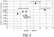
- FIG. 3 shows a graph obtained by plotting results of the above calculations.
- the vertical axis represents the moment of inertia Js of the static system (total), and the horizontal axis represents (m1/D1)/(m2/D2).
- a larger moment of inertia Js of the static system on the vertical axis means smaller vibration.
- the moment of inertia Js of the static system is smaller than that of a related-art machine (reference compressor) (the maximum moment of inertia Js of the static system is 0.011 [kg ⁇ m 2 ], which is in an allowable range of a vibration reduction effect).
- the moment of inertia Js of the static system equal to or more than a predetermined value (0.006 [kg ⁇ m 2 ]), which is allowable as a value for vibration reduction.
- the compressor 1 can be evaluated in distinction from the related-art machine (reference compressor). This serves as an effective indicator for evaluating miniaturization of the compressor main body 10.
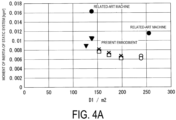
- the compressor 1 cannot be distinguished from the related-art machine, and miniaturization and vibration reduction cannot be evaluated at the same time.
- D1/m2 that is, a value obtained by dividing the outside diameter D1 of the compressor main body 10 by the mass m2 of the accumulator 12 is used as a parameter of the horizontal axis.
- plotted points of the present embodiment are overlapped with values of the related-art machine (reference compressor) on the horizontal axis, and they cannot be distinguished from each other.
- m1/m2 that is, a value obtained by dividing the mass m1 of the compressor main body 10 by the mass m2 of the accumulator 12 is used as a parameter of the horizontal axis.
- plotted points of the present embodiment are overlapped with values of the related-art machine (reference compressor) on the horizontal axis, and they cannot be distinguished from each other.
- the vibration can be reduced in the range of 3 ⁇ (m1/D1)/(m2/D2) ⁇ 7.
- a weight adding member may be attached to the accumulator 12 so as to adjust the mass m2 of the accumulator 12.
- the weight adding member is mainly used to increase the mass m2 of the accumulator 12 and is irrelevant to the essential function of the accumulator 12.
- rubber particularly, butyl rubber having a high specific weight
- the rubber is attached to the outside surface of the accumulator 12, for example.
- a compressor (1) is a compressor including a compressor main body (10) including, in a tubular housing (2), a compression unit (6) compressing a refrigerant, and a tubular accumulator (12) coupled to a refrigerant suction portion of the compressor main body, in which 3 ⁇ (m1/D1)/(m2/D2) ⁇ 7, where m1 is a mass of the compressor main body, m2 is a mass of the accumulator, D1 is an outside diameter of the compressor main body, and D2 is an outside diameter of the accumulator.
- vibration can be reduced in the range of 3 ⁇ (m1/D1)/(m2/D2) ⁇ 7, where m1 is the mass of the compressor main body, m2 is the mass of the accumulator, D1 is the outside diameter of the compressor main body, and D2 is the outside diameter of the accumulator.
- a compressor according to a second aspect of the present disclosure is the compressor according to the first aspect, in which
- a compressor according to a third aspect of the present disclosure is the compressor according to the first aspect or the second aspect, in which a mildly flammable refrigerant, a flammable refrigerant, or a strongly flammable refrigerant is used as the refrigerant.
- a compressor according to a fourth aspect of the present disclosure is the compressor according to any of the first aspect to the third aspect, in which a weight adding member adjusting the m2 is attached to the accumulator.
- the above relationship for achieving vibration reduction may be satisfied by adjusting the mass m2 of the accumulator.
- the weight adding member is mainly used to increase the weight of the accumulator and is irrelevant to the essential function of the accumulator.
- rubber specifically, butyl rubber having a large specific gravity
- the rubber is attached to the outside surface of the accumulator, for example.
- a method for designing a compressor according to a fifth aspect of the present disclosure is a method for designing a compressor, the compressor including a compressor main body including, in a tubular housing, a compression unit compressing a refrigerant, and a tubular accumulator coupled to a refrigerant suction portion of the compressor main body, in which 3 ⁇ (m1/D1)/(m2/D2) ⁇ 7, where m1 is a mass of the compressor main body, m2 is a mass of the accumulator, D1 is an outside diameter of the compressor main body, and D2 is an outside diameter of the accumulator.
Landscapes
- Engineering & Computer Science (AREA)
- Mechanical Engineering (AREA)
- General Engineering & Computer Science (AREA)
- Compressor (AREA)
- Applications Or Details Of Rotary Compressors (AREA)
Abstract
Description
- The present disclosure relates to a compressor and a method for designing the compressor.
- A rotary compressor is known as one of compressors used in refrigeration devices, air-conditioning devices, and the like.
- As described in Patent Document 1, propagation of vibration of a rotary compressor to an inlet tube of an accumulator is problematic. When a refrigerant pipe is broken due to the vibration propagated to the inlet tube of the accumulator, a refrigerant inside the pipe may leak to the outside. In particular, when a flammable refrigerant (as an example of a flammability class, a mildly flammable refrigerant (A2L), a flammable refrigerant (A2), or a strongly flammable refrigerant (A3)) is used as the refrigerant, it is more necessary to avoid leakage of the refrigerant.
- In addition, when the rotary compressor vibrates, mountability to a product can be deteriorated.
- Patent Document 1:
JP 2011-185123 A - In a related-art rotary compressor having a relatively large weight, the moment of inertia of a static system is large, and thus vibration caused by driving of a rotary compression unit (for example, rotation of a piston rotor), which is a rotating system, tends to be suppressed. However, due to miniaturization of the rotary compressor, the moment of inertia of the static system may decrease and a problem related to vibration may become apparent.
- The present disclosure has been made in view of such circumstances, and an object thereof is to provide a compressor capable of reducing vibration even when a compressor main body is miniaturized and a method for designing the compressor.
- A compressor (1) according to an aspect of the present disclosure is a compressor including a compressor main body (10) including, in a tubular housing (2), a compression unit (6) compressing a refrigerant, and a tubular accumulator (12) coupled to a refrigerant suction portion of the compressor main body, in which 3 ≤ (m1/D1)/(m2/D2) ≤ 7, where m1 is a mass of the compressor main body, m2 is a mass of the accumulator, D1 is an outside diameter of the compressor main body, and D2 is an outside diameter of the accumulator.
- A method for designing a compressor according to another aspect of the present disclosure is a method for designing a compressor, the compressor including a compressor main body including, in a tubular housing, a compression unit compressing a refrigerant, and a tubular accumulator coupled to a refrigerant suction portion of the compressor main body, in which 3 ≤ (m1/D1)/(m2/D2) ≤ 7, where m1 is a mass of the compressor main body, m2 is a mass of the accumulator, D1 is an outside diameter of the compressor main body, and D2 is an outside diameter of the accumulator.
- It is possible to reduce vibration even when a compressor is miniaturized.
-
-
FIG. 1 is a vertical cross-sectional view illustrating a rotary compressor according to an embodiment of the present disclosure. -
FIG. 2 is a side view illustrating a state in which the rotary compressor ofFIG. 1 is provided at an installation surface. -
FIG. 3 is a graph showing a vibration reduction effect when the compressor of the present disclosure is miniaturized. -
FIG. 4A is a graph of a comparative example ofFIG. 3 when the horizontal axis is D1/m2. -
FIG. 4B is a graph of a comparative example ofFIG. 3 when the horizontal axis is m1/m2. - An embodiment according to the present disclosure will be described below with reference to the drawings.
- As illustrated in
FIG. 1 , a rotary compressor (hereinafter simply referred to as a "compressor") 1 according to the present embodiment is a hermetically sealed electric rotary compressor used in, for example, an air conditioner or a refrigeration device. The compressor 1 includes a compressormain body 10 and anaccumulator 12. Theaccumulator 12 is coupled to the compressormain body 10 via asuction tube 11. - The compressor
main body 10 includes ahousing 2 having a substantially cylindrical shape, arotor shaft body 3, anelectric motor 5, and arotary compression unit 6. An axis of rotation CL of therotor shaft body 3 coincides with the center axis of thehousing 2. Therotor shaft body 3 is disposed so as to extend in the vertical direction and rotates about the axis of rotation CL in thehousing 2. - The
housing 2 is hermetically sealed and extends in the vertical direction. Thehousing 2 includes a cylindricalmain body portion 21, and anupper lid portion 22 and alower lid portion 23 that close upper and lower openings of themain body portion 21. - A plurality of
leg portions 7 are fixed to a lower portion of themain body portion 21. Theleg portions 7 are disposed in the circumferential direction of themain body portion 21 at predetermined angular intervals. As illustrated inFIG. 2 , eachleg portion 7 is fixed to an installation surface FL via a vibration-proof rubber 8. - An
opening 24 is formed at a position facing the outside surface of acylinder 60 in a lower portion of the side wall of thehousing 2. In thecylinder 60, asuction port 25 that communicates to a predetermined position in the cylinder is formed at a position facing theopening 24. - An oil sump for storing lubricating oil is formed at a bottom portion of the
housing 2. The liquid level of the oil sump when the oil is initially sealed is located above therotary compression unit 6. Thus, therotary compression unit 6 is driven in the oil sump. - The
upper lid portion 22 is provided with adischarge tube 13 and aterminal block 30. Thedischarge tube 13 penetrates theupper lid portion 22 in the thickness direction and includes a lower portion disposed inside thehousing 2 and an upper portion disposed outside thehousing 2. Thedischarge tube 13 discharges a compressed refrigerant to the outside of thehousing 2. Theterminal block 30 is provided with threepower supply terminals 31 for supplying electric power to theelectric motor 5. Three-phase electric power is supplied to thepower supply terminals 31 from an inverter device (not illustrated). - The
accumulator 12 is used to separate a refrigerant into gas and liquid before supplying the refrigerant to the compressormain body 10. Theaccumulator 12 has a substantially cylindrical shape and is fixed to the outside surface of thehousing 2 via abracket 14. Aninlet tube 15 for introducing a refrigerant guided from an evaporator (not illustrated) is provided at an upper portion of theaccumulator 12. Thesuction tube 11 for causing the refrigerant inside theaccumulator 12 to be sucked into the compressormain body 10 is coupled to a lower portion of theaccumulator 12. Thesuction tube 11 is coupled to thesuction port 25 through the opening 24 of thehousing 2. Theaccumulator 12 supplies the gas-phase refrigerant to therotary compression unit 6 through thesuction tube 11. - As the refrigerant, a flammable refrigerant, that is, a refrigerant in a flammability class of a mildly flammable refrigerant (A2L), a flammable refrigerant (A2), or a strongly flammable refrigerant (A3) such as propane, is used.
- The
electric motor 5 is accommodated at a central portion of thehousing 2 in the vertical direction. Theelectric motor 5 includes arotor 51 and astator 52. Therotor 51 is fixed to the outside surface of therotor shaft body 3 and is disposed above therotary compression unit 6. Thestator 52 is disposed so as to surround the outside surface of therotor 51 and is fixed to aninner surface 21a of themain body portion 21 of thehousing 2. - Electric power is supplied to the
stator 52 from eachpower supply terminal 31 through awiring line 32. Theelectric motor 5 rotates therotor shaft body 3 by electric power supplied from eachpower supply terminal 31. - The
rotary compression unit 6 is disposed in a state of being vertically interposed between an upper bearing 4A and a lower bearing 4B. The upper bearing 4A and thelower bearing 4B are each formed of a metal material and are fixed to thecylinder 60 constituting therotary compression unit 6 with abolt 61. - The
rotor shaft body 3 is supported by theupper bearing 4A and thelower bearing 4B in a rotatable manner about the axis of rotation CL. - The
rotary compression unit 6 is disposed at a bottom portion in thehousing 2 below theelectric motor 5. Therotary compression unit 6 includes thecylinder 60, aneccentric shaft portion 62, and apiston rotor 63. - A
compression chamber 60A, asuction hole 60B, and a discharge hole (not illustrated) are formed in thecylinder 60. Thecompression chamber 60A is formed inside thecylinder 60. Thepiston rotor 63 is accommodated in thecompression chamber 60A. - The
rotary compression unit 6 is fixed to theinner surface 21a of themain body portion 21 of thehousing 2. Specifically, theupper bearing 4A sandwiching thecylinder 60 is fixed to theinner surface 21a of themain body portion 21 of thehousing 2. Theupper bearing 4A is fixed by plug-welding at a plurality of positions in the circumferential direction of thehousing 2. Note that instead of plug welding, shrink fitting, cold fitting, or the like may be performed. - The
eccentric shaft portion 62 is provided at a lower end portion of therotor shaft body 3 and is provided inside thepiston rotor 63 in a state of being offset in an orthogonal direction from the central axis of therotor shaft body 3. - The
piston rotor 63 has a cylindrical shape having an outside diameter smaller than the inside diameter of thecylinder 60, is disposed inside thecylinder 60, and is fixed in a state of being mounted at the outside periphery of theeccentric shaft portion 62. Thepiston rotor 63 eccentrically rotates about the axis of rotation CL along with the rotation of therotor shaft body 3. - The
suction hole 60B is a hole for guiding the refrigerant to the inside of thecylinder 60 and is formed in a direction orthogonal to the axis of rotation CL. - The high-pressure refrigerant discharged from the discharge hole (not illustrated) formed in the
cylinder 60 is guided into a space formed between adischarge cover 65 and theupper bearing 4A and then guided into the internal space of thehousing 2. - The above-described compressor 1 operates as follows.
- A refrigerant guided from the evaporator (not illustrated) is taken into the
accumulator 12 through theinlet tube 15. The refrigerant is separated into gas and liquid in theaccumulator 12, and the gas-phase refrigerant is guided to therotary compression unit 6 through thesuction tube 11. In therotary compression unit 6, the refrigerant is guided to thecompression chamber 60A through thesuction hole 60B. Then, eccentric rotation of thepiston rotor 63 gradually decreases the volume of thecompression chamber 60A and compresses the refrigerant. The compressed refrigerant passes through the space inside thedischarge cover 65 through the discharge hole and is then guided to the internal space of thehousing 2. The refrigerant discharged into the internal space of thehousing 2 is guided to a condenser (not illustrated) through thedischarge tube 13 provided at the upper portion of thehousing 2. - Next, vibration when the compressor 1 operates will be described.
- Vibration caused by the operation of the compressor 1 is generated from a drive unit of a rotating system such as the
piston rotor 63 and propagated from the compressormain body 10 to theaccumulator 12. - The specifications used for vibration calculation are as follows.
- Mass of the compressor main body 10: m1 [kg]
- Mass of the accumulator 12: m2 [kg]
- Outside diameter of the compressor main body 10: D1 (see
FIG. 2 ) [m] - Outside diameter of the accumulator 12: D2 (see
FIG. 2 ) [m] - Distance between the axis of rotation CL and a center axis CL2 of the inlet tube 15: Rg (see
FIG. 2 ) [m] - Displacement amount of the rotary compression unit 6: V [cc/rev]
- Mass of the refrigeration oil: m0 [kg]:
- Mass of the rotating system: mr [kg]
- Here, the rotating system refers to rotating members, that is, the
rotor shaft body 3, therotor 51, and thepiston rotor 63. Thus, the static system refers to a configuration other than the rotating system, that is, the compressormain body 10 and theaccumulator 12 exclusive of the rotating system. - The numerical values of m1, m2, D1 and D2 are in the following ranges.
- 4 kg ≤ m1 ≤ 6 kg
- 0.3 kg ≤ m2 ≤ 0.7 kg
- 80 mm ≤ D1 ≤ 95 mm
- 50 mm ≤ D2 ≤ 75 mm
- The moment of inertia of the static system and the moment of inertia of the rotating system are as follows.
- Static System
- Moment of inertia (compressor main body):

- Moment of inertia (accumulator):

- Moment of inertia (total):

- Rotating system
- Moment of inertia: Jr [kg-m2]
- When vibration of an
inlet tube 15 of anaccumulator 12 of a reference compressor (related-art compressor) at a time of design is A [m], vibration A' [m] of theinlet tube 15 of the compressor 1 of the present embodiment in comparison with the reference compressor is simply represented by the following equations.

- The terms of the above equation of α have the following physical meanings:
- Excitation force (proportional to the displacement amount): (V/V') times
- Rotation speed variation (proportional to Jr- 1): (Jr'/Jr) times
- Angular speed of the rotary compression unit 6 (proportional to Js- 1): (Js'/Js) times
- Rotational direction acceleration of the inlet tube 15 (proportional to Rg): (Rg/Rg') times
-
FIG. 3 shows a graph obtained by plotting results of the above calculations. - In the figure, the vertical axis represents the moment of inertia Js of the static system (total), and the horizontal axis represents (m1/D1)/(m2/D2).
- A larger moment of inertia Js of the static system on the vertical axis means smaller vibration.
- As can be seen from
FIG. 3 , by designing the range of (m1/D1)/(m2/D2) to be equal to or more than 3 and equal to or less than 7, the moment of inertia Js of the static system is smaller than that of a related-art machine (reference compressor) (the maximum moment of inertia Js of the static system is 0.011 [kg·m2], which is in an allowable range of a vibration reduction effect). In addition, it is possible to obtain the moment of inertia Js of the static system equal to or more than a predetermined value (0.006 [kg·m2]), which is allowable as a value for vibration reduction. - Further, as can be seen from the figure, by using the parameter (m1/D1)/(m2/D2), the compressor 1 can be evaluated in distinction from the related-art machine (reference compressor). This serves as an effective indicator for evaluating miniaturization of the compressor
main body 10. - For example, when parameters are set as in respective comparative examples described below, the compressor 1 cannot be distinguished from the related-art machine, and miniaturization and vibration reduction cannot be evaluated at the same time.
- In
FIG. 4A , D1/m2, that is, a value obtained by dividing the outside diameter D1 of the compressormain body 10 by the mass m2 of theaccumulator 12 is used as a parameter of the horizontal axis. As can be seen from the figure, plotted points of the present embodiment are overlapped with values of the related-art machine (reference compressor) on the horizontal axis, and they cannot be distinguished from each other. - In
FIG. 4B , m1/m2, that is, a value obtained by dividing the mass m1 of the compressormain body 10 by the mass m2 of theaccumulator 12 is used as a parameter of the horizontal axis. As can be seen from the figure, plotted points of the present embodiment are overlapped with values of the related-art machine (reference compressor) on the horizontal axis, and they cannot be distinguished from each other. - As can be understood with reference to
FIGS. 3 ,4A and4B , by appropriately selecting a parameter as illustrated inFIG. 3 , it is possible to evaluate the compressor in distinction from the related-art machine (reference compressor). - The operational effects of the present embodiment described above are as follows.
- Miniaturization of the compressor
main body 10 decreases the mass. Thus, the moment of inertia of the static system decreases and vibration during operation tends to increase. On the other hand, as a result of studies conducted by the present inventors and the like, it has been found that there is a range in which vibration can be reduced in terms of the relationship between the mass m1 and the outside diameter D1 of the compressormain body 10 and the mass m2 and the outside diameter D2 of theaccumulator 12. - That is, even when the compressor
main body 10 is miniaturized, the vibration can be reduced in the range of 3 ≤ (m1/D1)/(m2/D2) ≤ 7. - Even when a mildly flammable refrigerant (A2L), a flammable refrigerant (A2), or a strongly flammable refrigerant (A3) is used as the refrigerant, since the compressor 1 with less vibration during operation is provided, it is possible to reduce the possibility that the refrigerant leaks due to breakage of a pipe coupled to the
inlet tube 15 as much as possible. - A weight adding member may be attached to the
accumulator 12 so as to adjust the mass m2 of theaccumulator 12. The weight adding member is mainly used to increase the mass m2 of theaccumulator 12 and is irrelevant to the essential function of theaccumulator 12. For example, rubber (particularly, butyl rubber having a high specific weight) is used. When rubber is used, the rubber is attached to the outside surface of theaccumulator 12, for example. - The compressor and the design method therefor described in the above-described embodiment can be understood, for example, as follows.
- A compressor (1) according to a first aspect of the present disclosure is a compressor including a compressor main body (10) including, in a tubular housing (2), a compression unit (6) compressing a refrigerant, and a tubular accumulator (12) coupled to a refrigerant suction portion of the compressor main body, in which 3 ≤ (m1/D1)/(m2/D2) ≤ 7, where m1 is a mass of the compressor main body, m2 is a mass of the accumulator, D1 is an outside diameter of the compressor main body, and D2 is an outside diameter of the accumulator.
- Miniaturization of the compressor main body decreases the mass. Thus, the moment of inertia of the static system decrease and vibration during operation tends to increase. On the other hand, as a result of studies conducted by the present inventors and the like, it has been found that there is a range in which vibration can be reduced in terms of the relationship between the mass and the outside diameter of the compressor main body and the mass and the outside diameter of the accumulator. That is, even when the compressor main body is miniaturized, vibration can be reduced in the range of 3 ≤ (m1/D1)/(m2/D2) ≤ 7, where m1 is the mass of the compressor main body, m2 is the mass of the accumulator, D1 is the outside diameter of the compressor main body, and D2 is the outside diameter of the accumulator.
- A compressor according to a second aspect of the present disclosure is the compressor according to the first aspect, in which
- 4 kg ≤ m1 ≤ 6 kg,
- 0.3 kg ≤ m2 ≤ 0.7 kg,
- 80 mm ≤ D1 ≤ 95 mm, and
- 50 mm ≤ D2 ≤ 75 mm.
- When the masses and the outside diameters are within the above-described ranges, a miniaturized compressor can be achieved.
- A compressor according to a third aspect of the present disclosure is the compressor according to the first aspect or the second aspect, in which a mildly flammable refrigerant, a flammable refrigerant, or a strongly flammable refrigerant is used as the refrigerant.
- Even when the mildly flammable refrigerant (A2L), the flammable refrigerant (A2), or the strongly flammable refrigerant (A3) is used, since the compressor with less vibration during operation is provided, it is possible to reduce the possibility that the refrigerant leaks due to breakage of a pipe or the like.
- A compressor according to a fourth aspect of the present disclosure is the compressor according to any of the first aspect to the third aspect, in which a weight adding member adjusting the m2 is attached to the accumulator.
- The above relationship for achieving vibration reduction may be satisfied by adjusting the mass m2 of the accumulator. The weight adding member is mainly used to increase the weight of the accumulator and is irrelevant to the essential function of the accumulator. For example, rubber (specifically, butyl rubber having a large specific gravity) is used. When rubber is used, the rubber is attached to the outside surface of the accumulator, for example.
- A method for designing a compressor according to a fifth aspect of the present disclosure is a method for designing a compressor, the compressor including a compressor main body including, in a tubular housing, a compression unit compressing a refrigerant, and a tubular accumulator coupled to a refrigerant suction portion of the compressor main body, in which 3 ≤ (m1/D1)/(m2/D2) ≤ 7, where m1 is a mass of the compressor main body, m2 is a mass of the accumulator, D1 is an outside diameter of the compressor main body, and D2 is an outside diameter of the accumulator.
-
- 1 Compressor (rotary compressor)
- 2 Housing
- 3 Rotor shaft body
- 4A Upper bearing
- 4B Lower bearing
- 5 Electric motor
- 6 Rotary compression unit (compression unit)
- 7 Leg portion
- 8 Vibration-proof rubber
- 10 Compressor main body
- 11 Suction tube
- 12 Accumulator
- 13 Discharge tube
- 14 Bracket
- 15 Inlet tube
- 21 Main body portion
- 21a Inner surface
- 22 Upper lid portion
- 23 Lower lid portion
- 24 Opening
- 25 Suction port
- 30 Terminal block
- 31 Power supply terminal
- 32 Wiring line
- 51 Rotor
- 52 Stator
- 60 Cylinder
- 60A Compression chamber
- 60B Suction hole
- 61 Bolt
- 62 Eccentric shaft portion
- 63 Piston rotor
- 65 Discharge cover
- CL Axis of rotation
- CL2 Center axis of the inlet tube
- FL Installation surface
Claims (5)
- A compressor comprising:a compressor main body including, in a tubular housing, a compression unit configured to compress a refrigerant; anda tubular accumulator coupled to a refrigerant suction portion of the compressor main body, wherein3 ≤ (m1/D1)/(m2/D2) ≤ 7, where m1 is a mass of the compressor main body, m2 is a mass of the accumulator, D1 is an outside diameter of the compressor main body, and D2 is an outside diameter of the accumulator.
- The compressor according to claim 1, wherein4 kg ≤ m1 ≤ 6 kg,0.3 kg ≤ m2 ≤ 0.7 kg,80 mm ≤ D1 ≤ 95 mm, and50 mm ≤ D2 ≤ 75 mm.
- The compressor according to claim 1 or 2, wherein
a mildly flammable refrigerant, a flammable refrigerant, or a strongly flammable refrigerant is used as the refrigerant. - The compressor according to claim 1 or 2, wherein
a weight adding member configured to adjust the m2 is attached to the accumulator. - A method for designing a compressor, the compressor including a compressor main body including, in a tubular housing, a compression unit configured to compress a refrigerant, and a tubular accumulator coupled to a refrigerant suction portion of the compressor main body, wherein
3 ≤ (m1/D1)/(m2/D2) ≤ 7, where m1 is a mass of the compressor main body, m2 is a mass of the accumulator, D1 is an outside diameter of the compressor main body, and D2 is an outside diameter of the accumulator.
Applications Claiming Priority (2)
| Application Number | Priority Date | Filing Date | Title |
|---|---|---|---|
| JP2022093807A JP7467531B2 (en) | 2022-06-09 | 2022-06-09 | Compressor and design method thereof |
| PCT/JP2023/019761 WO2023238709A1 (en) | 2022-06-09 | 2023-05-26 | Compressor and design method for same |
Publications (2)
| Publication Number | Publication Date |
|---|---|
| EP4417814A1 true EP4417814A1 (en) | 2024-08-21 |
| EP4417814A4 EP4417814A4 (en) | 2025-03-12 |
Family
ID=89118163
Family Applications (1)
| Application Number | Title | Priority Date | Filing Date |
|---|---|---|---|
| EP23819691.9A Pending EP4417814A4 (en) | 2022-06-09 | 2023-05-26 | COMPRESSOR AND ITS DESIGN METHOD |
Country Status (5)
| Country | Link |
|---|---|
| EP (1) | EP4417814A4 (en) |
| JP (1) | JP7467531B2 (en) |
| CN (1) | CN118318105A (en) |
| AU (1) | AU2023282649B2 (en) |
| WO (1) | WO2023238709A1 (en) |
Family Cites Families (8)
| Publication number | Priority date | Publication date | Assignee | Title |
|---|---|---|---|---|
| JP2820463B2 (en) * | 1989-11-02 | 1998-11-05 | 松下電器産業株式会社 | How to start the scroll compressor |
| JP2009097394A (en) * | 2007-10-16 | 2009-05-07 | Panasonic Corp | Hermetic compressor |
| JP2011185123A (en) | 2010-03-05 | 2011-09-22 | Daikin Industries Ltd | Compressor unit, air conditioner, and water heater |
| JP2014092078A (en) * | 2012-11-05 | 2014-05-19 | Daikin Ind Ltd | Compressor |
| WO2016079801A1 (en) * | 2014-11-18 | 2016-05-26 | 三菱電機株式会社 | Air conditioning device |
| US10550843B2 (en) * | 2015-01-13 | 2020-02-04 | Fujitsu General Limited | Rotary compressor |
| JP6896147B2 (en) * | 2018-03-14 | 2021-06-30 | 三菱電機株式会社 | Compressor |
| JP6696537B2 (en) * | 2018-08-09 | 2020-05-20 | ダイキン工業株式会社 | Compressor and method of manufacturing compressor |
-
2022
- 2022-06-09 JP JP2022093807A patent/JP7467531B2/en active Active
-
2023
- 2023-05-26 CN CN202380014442.9A patent/CN118318105A/en active Pending
- 2023-05-26 AU AU2023282649A patent/AU2023282649B2/en active Active
- 2023-05-26 WO PCT/JP2023/019761 patent/WO2023238709A1/en not_active Ceased
- 2023-05-26 EP EP23819691.9A patent/EP4417814A4/en active Pending
Also Published As
| Publication number | Publication date |
|---|---|
| CN118318105A (en) | 2024-07-09 |
| JP2023180460A (en) | 2023-12-21 |
| WO2023238709A1 (en) | 2023-12-14 |
| AU2023282649A1 (en) | 2024-05-23 |
| AU2023282649B2 (en) | 2025-10-02 |
| JP7467531B2 (en) | 2024-04-15 |
| EP4417814A4 (en) | 2025-03-12 |
Similar Documents
| Publication | Publication Date | Title |
|---|---|---|
| US10851782B2 (en) | Rotary-type compressor | |
| JPWO2013171957A1 (en) | Electric compressor | |
| EP4513038A1 (en) | Rotary compressor and method for manufacturing rotary compressor | |
| EP2129912B1 (en) | Mount for compressor shell | |
| JP7348568B2 (en) | outdoor unit | |
| KR101718037B1 (en) | Enclosed compressor | |
| AU2023282649A1 (en) | Compressor and method for designing the same | |
| EP4424996A1 (en) | Rotary compressor | |
| EP4621242A1 (en) | Compressor | |
| KR101462934B1 (en) | Hermetic compressor | |
| EP4517092A1 (en) | Rotary compressor | |
| EP4400722B1 (en) | Compressor | |
| EP4400716B1 (en) | Compressor | |
| EP4621241A1 (en) | Compressor | |
| EP4400724A1 (en) | Compressor | |
| US12152590B2 (en) | Scroll compressor | |
| KR100469271B1 (en) | Scroll compressor with outer rotor type motor | |
| JP2013209965A (en) | Compressor |
Legal Events
| Date | Code | Title | Description |
|---|---|---|---|
| STAA | Information on the status of an ep patent application or granted ep patent |
Free format text: STATUS: THE INTERNATIONAL PUBLICATION HAS BEEN MADE |
|
| PUAI | Public reference made under article 153(3) epc to a published international application that has entered the european phase |
Free format text: ORIGINAL CODE: 0009012 |
|
| STAA | Information on the status of an ep patent application or granted ep patent |
Free format text: STATUS: REQUEST FOR EXAMINATION WAS MADE |
|
| 17P | Request for examination filed |
Effective date: 20240515 |
|
| AK | Designated contracting states |
Kind code of ref document: A1 Designated state(s): AL AT BE BG CH CY CZ DE DK EE ES FI FR GB GR HR HU IE IS IT LI LT LU LV MC ME MK MT NL NO PL PT RO RS SE SI SK SM TR |
|
| A4 | Supplementary search report drawn up and despatched |
Effective date: 20250207 |
|
| RIC1 | Information provided on ipc code assigned before grant |
Ipc: F01C 21/10 20060101ALI20250203BHEP Ipc: F04C 29/12 20060101ALI20250203BHEP Ipc: F04B 39/00 20060101ALI20250203BHEP Ipc: F04C 29/06 20060101AFI20250203BHEP |
|
| DAV | Request for validation of the european patent (deleted) | ||
| DAX | Request for extension of the european patent (deleted) |