EP4417805A1 - Gas turbine engine nozzle for thurst reverser - Google Patents
Gas turbine engine nozzle for thurst reverser Download PDFInfo
- Publication number
- EP4417805A1 EP4417805A1 EP24157464.9A EP24157464A EP4417805A1 EP 4417805 A1 EP4417805 A1 EP 4417805A1 EP 24157464 A EP24157464 A EP 24157464A EP 4417805 A1 EP4417805 A1 EP 4417805A1
- Authority
- EP
- European Patent Office
- Prior art keywords
- thrust reverser
- openings
- radius
- offset
- forward side
- Prior art date
- Legal status (The legal status is an assumption and is not a legal conclusion. Google has not performed a legal analysis and makes no representation as to the accuracy of the status listed.)
- Granted
Links
Images



Classifications
-
- F—MECHANICAL ENGINEERING; LIGHTING; HEATING; WEAPONS; BLASTING
- F02—COMBUSTION ENGINES; HOT-GAS OR COMBUSTION-PRODUCT ENGINE PLANTS
- F02K—JET-PROPULSION PLANTS
- F02K1/00—Plants characterised by the form or arrangement of the jet pipe or nozzle; Jet pipes or nozzles peculiar thereto
- F02K1/54—Nozzles having means for reversing jet thrust
- F02K1/56—Reversing jet main flow
- F02K1/60—Reversing jet main flow by blocking the rearward discharge by means of pivoted eyelids or clamshells, e.g. target-type reversers
-
- F—MECHANICAL ENGINEERING; LIGHTING; HEATING; WEAPONS; BLASTING
- F02—COMBUSTION ENGINES; HOT-GAS OR COMBUSTION-PRODUCT ENGINE PLANTS
- F02K—JET-PROPULSION PLANTS
- F02K1/00—Plants characterised by the form or arrangement of the jet pipe or nozzle; Jet pipes or nozzles peculiar thereto
- F02K1/54—Nozzles having means for reversing jet thrust
- F02K1/56—Reversing jet main flow
- F02K1/58—Reversers mounted on the inner cone or the nozzle housing or the fuselage
-
- F—MECHANICAL ENGINEERING; LIGHTING; HEATING; WEAPONS; BLASTING
- F02—COMBUSTION ENGINES; HOT-GAS OR COMBUSTION-PRODUCT ENGINE PLANTS
- F02K—JET-PROPULSION PLANTS
- F02K1/00—Plants characterised by the form or arrangement of the jet pipe or nozzle; Jet pipes or nozzles peculiar thereto
- F02K1/54—Nozzles having means for reversing jet thrust
- F02K1/56—Reversing jet main flow
- F02K1/62—Reversing jet main flow by blocking the rearward discharge by means of flaps
-
- F—MECHANICAL ENGINEERING; LIGHTING; HEATING; WEAPONS; BLASTING
- F05—INDEXING SCHEMES RELATING TO ENGINES OR PUMPS IN VARIOUS SUBCLASSES OF CLASSES F01-F04
- F05D—INDEXING SCHEME FOR ASPECTS RELATING TO NON-POSITIVE-DISPLACEMENT MACHINES OR ENGINES, GAS-TURBINES OR JET-PROPULSION PLANTS
- F05D2220/00—Application
- F05D2220/30—Application in turbines
- F05D2220/32—Application in turbines in gas turbines
- F05D2220/323—Application in turbines in gas turbines for aircraft propulsion, e.g. jet engines
-
- F—MECHANICAL ENGINEERING; LIGHTING; HEATING; WEAPONS; BLASTING
- F05—INDEXING SCHEMES RELATING TO ENGINES OR PUMPS IN VARIOUS SUBCLASSES OF CLASSES F01-F04
- F05D—INDEXING SCHEME FOR ASPECTS RELATING TO NON-POSITIVE-DISPLACEMENT MACHINES OR ENGINES, GAS-TURBINES OR JET-PROPULSION PLANTS
- F05D2250/00—Geometry
- F05D2250/10—Two-dimensional
- F05D2250/14—Two-dimensional elliptical
-
- F—MECHANICAL ENGINEERING; LIGHTING; HEATING; WEAPONS; BLASTING
- F05—INDEXING SCHEMES RELATING TO ENGINES OR PUMPS IN VARIOUS SUBCLASSES OF CLASSES F01-F04
- F05D—INDEXING SCHEME FOR ASPECTS RELATING TO NON-POSITIVE-DISPLACEMENT MACHINES OR ENGINES, GAS-TURBINES OR JET-PROPULSION PLANTS
- F05D2250/00—Geometry
- F05D2250/10—Two-dimensional
- F05D2250/14—Two-dimensional elliptical
- F05D2250/141—Two-dimensional elliptical circular
Definitions
- a turbine engine is typically mounted within a nacelle structure that supports a core engine and may also define a bypass flow path. Exhaust gases and any bypass flows are directed through the nacelle structure and exhausted through a nozzle.
- the nozzle defines a flow area for exhausting the flows to generate a forward propulsive thrust.
- Nozzles may include a thrust reverser to enhance stopping power of an aircraft during landing.
- the thrust reverser includes doors that open and direct propulsive thrust forward toward a nose of the aircraft. In a deployed position, the nozzle gas path is defined through an opening defined by the open doors.
- Turbine engine manufacturers continue to seek improvements to engine performance including improvements to thermal, transfer, weight and propulsive efficiencies.
- An engine nacelle assembly includes a nacelle that defines a flow path between an intake end and an exhaust end, and a nozzle that is disposed at the exhaust end of the nacelle about a central axis.
- the nozzle includes opposing thrust reverser openings and thrust reverser doors.
- a cross-sectional area transverse to the central axis proximate a forward side of each of the opposing thrust reverser openings is oval shaped with an offset radius within offset arc segments that are aligned with the opposing thrust reverser openings and a first radius outside of the offset arc segment. The first radius is less than the offset radius.
- a thrust reverser for a turbine engine includes a nozzle that includes an inlet and exit spaced axially apart along a central axis, opposing thrust reverser openings and first and second side arms are disposed on either side of each of the opposing thrust reverser openings, and thrust reverser doors that are movable between a closed position that covers a corresponding one of the opposing thrust reverser openings and an open position uncovering the opposing thrust reverser openings.
- a cross-sectional area transverse to the central axis proximate a forward side of each of the opposing thrust reverser openings is oval shaped with an offset radius within offset arc segments that are aligned with the opposing thrust reverser openings and a first radius outside of the offset arc segment. The first radius is less than the offset radius.
- a turbine engine assembly includes a core engine, a nacelle that surrounds at least a portion of the core engine that defines a flow path between an intake end and an exhaust end, and a nozzle that is disposed at the exhaust end of the nacelle.
- the nozzle includes an inlet and exit spaced apart axially along a central axis, opposing thrust reverser openings, and thrust reverser doors that are movable between a closed position that covers a corresponding one of the opposing thrust reverser openings and an open position that uncovers the opposing thrust reverser openings.
- a cross-sectional area that is transverse to the central axis proximate a forward side of each of the opposing thrust reverser openings is oval shaped with an offset radius within offset arc segments that are aligned with the opposing thrust reverser openings and a first radius outside of the offset arc segment. The first radius is less than the offset radius.
- FIG. 1 schematically illustrates a gas turbine engine 20.
- the example gas turbine engine 20 is a turbofan that generally incorporates a core engine 25, a fan section 22, a compressor section 24, a combustor section 26 and a turbine section 28.
- the fan section 22 drives air along a bypass flow path B in a bypass duct defined within a nacelle 30.
- the compressor section 24 drives air along a core flow path C into the compressor section 24 for compression and communication into the combustor section 26.
- the compressed air is mixed with fuel from a fuel system 32 and ignited by igniter 34 to generate an exhaust gas flow that expands through the turbine section 28 and is exhausted past tail cone 36.
- turbofan turbine engine in the disclosed non-limiting embodiment, it should be understood that the concepts described herein are not limited to use with turbofans as the teachings may be applied to other types of turbine engines. Moreover, although turbine engines are described by way of example, other engine configurations such as internal combustion engines could be utilized and are within the contemplation of this disclosure.
- the nacelle 30 includes an intake end 42 and an exhaust end 44.
- a thrust reversing nozzle 38 is disposed at the exhaust end 44.
- the nozzle 38 defines an exhaust flow path between an inlet 46 and an exit 48.
- the nozzle 38 is attached to the exhaust end 44 of the nacelle 30.
- nozzle 38 includes opposing thrust reverser openings 50 that are covered by thrust reverser doors 52 when in a closed position.
- the thrust reverser doors 52 In an open or deployed position, the thrust reverser doors 52 uncover the thrust reverser openings 50 to direct flow 40 through the nozzle 38 forward towards a nose of the aircraft to provide faster deceleration.
- the opposing thrust reverser openings 50 and the inner surface of the thrust reversing doors 52 form the path for the flow 40.
- the example openings 50 and doors 52 are substantially the same, the openings 50 and doors 52 may be sized differently to provide different flow areas and remain with the contemplation and scope of this disclosure.
- the area of the openings 50 are defined between first and second arms 54, 56, the inner side of the thrust reverser doors 52 and by a cross-section through the nozzle 38 proximate a forward side 58 of each of the openings 50.
- the inner cross-sectional area of the nozzle 38 at the forward side 58 of each of the openings 50 further defines the flow area for the flow 40 when the thrust reverser doors 52 are deployed.
- the nozzle geometry is balanced to provide sufficient area to match other engine operating conditions during forward aircraft operation and thrust reverser performance.
- the example nozzle 38 includes an increased cross-sectional area at an axial position corresponding with the forward side 58 of each of the openings 50 to increase an effective area with the doors 52 deployed.
- the inlet and exit areas remain unchanged.
- the inlet and exit areas are substantially circular.
- the localized increase in the cross-sectional area at the openings 50 provides an increase in the effective flow area, without adjusting or changing other features of the nozzle 38, thereby maintaining desired performance during other engine operating conditions.
- the example inlet 46 and exit 48 are circular while the cross-section proximate the forward side 58 is offset to provide a local oval shape. Accordingly, in one disclosed example, an inner radius at each of the inlet 46 and the exit 48 is uniform about the central axis A to provide a circular cross-sectional area. An offset radius at the forward side 58 of each of the opposing openings 50 is increased at top and bottom circumferential positions to provide an oval cross-sectional flow area at an axial distance 68 from the inlet 46.
- the cross-section of the inlet 46 and exit 48 are shown by way of example as being circular with a uniform radius, other shapes could be utilized including elliptical, oval and other irregular shapes and remain with the contemplation and scope of this disclosure.
- the example nozzle 38 is shown as being symmetric about the axis A, the entire nozzle 38 or portions of the nozzle 38 may be asymmetric about the axis A and remain within the scope and contemplation of this disclosure.
- an inner peripheral surface 106 of the nozzle 38 within a plane 92 at the inlet 46 is of a constant radius 60 about the axis A to define a circular flow area ( Figure 4 ).
- the inner peripheral surface 108 of the nozzle 38 within the plane 94 at the exit 48 includes a constant radius 62 about the axis A to define a circular flow area ( Figure 6 ).
- An inner peripheral surface 110 within a plane 90 proximate the forward side 58 of each of the opposing openings 50 includes an offset radius 64 that is larger than a first radius 66 to define an oval-shaped flow area ( Figure 5 ).
- the example offset radius 64 tapers from the radius 66 to a maximum offset radius located along a central plane 84 ( Figure 5 ) transverse to the central axis A.
- the maximum radii are spaced apart a circumferentially as indicated at 74.
- the maximum offset radius is located at positions indicated at 72 that are spaced circumferentially apart 180 degrees.
- the axial location of the maximum offset radius 64 is shown as being proximate the forward side 58 of the openings 50 within the plane 90.
- the plane 90 is spaced the axial distance 68 from the inlet 46.
- the maximum offset radius positions 72 are disposed at the top center and bottom center positions.
- the maximum offset radius position may be tilted with respect to the central plane 84 and remain within the contemplation and scope of this disclosure.
- the increase in radius proximate the forward side 58 is provided by a first tapered inner surface 76 between the inlet 46 and the plane 90 proximate the forward side 58.
- the tapered inner surface 76 is disposed at a first angle 78 ( Figure 3 ).
- a second tapered inner surface 80 extends from the plane 90 proximate the forward side 58 to the exit 48.
- the second tapered inner surface 80 is disposed at a second angle 82 ( Figure 3 ).
- the second angle 82 is greater than the first angle 76 to provide for the transition from the elliptical cross-section to the circular cross-section at the exit 48.
- an offset 86 is shown as compared to a circular area shown by the dashed line circle indicated at 88.
- the offset 86 provides for an increased area within the solid outline 70 representing the inner surface of the nozzle 38 as compared to a circular area indicated by the dashed line 88.
- the offset 86 is disposed within offset arc segments 104 at top and bottom portions of the inner surface. The offset 86 increases in a direction toward the top and bottom maximum offset positions 72 of the inner surface.
- the cross-sectional area of the plane 90 within the nozzle at the axial distance 68 corresponding with the forward side 58 is between 1% and 10% greater than a cross-sectional area at the same axial location with a uniform radius about the central axis as represented by the dashed line circle 88. In another disclosed embodiment, the cross-sectional area is between 2% and 3% greater than cross-sectional area at the same axial location with a uniform radius about the central axis as represented by the dashed line circle 88.
- the maximum increased offset radius 64 is between 1% and 10% greater than the first inner radius 66 outside of the thrust reverser openings 50 at a common axial location defined along the central plane 84. In another example embodiment, the maximum offset radius 64 is between 2% and 3% greater than the inner radius 66 outside of the thrust reverser openings 50 at the common axial location defined along the central plane 84.
- the thrust reverser doors 52 and the first and second side arms 54 define the inner surface of the nozzle 38 from the plane 90 to the exit 48.
- the inner surface of the thrust reverser doors 52 are therefore spaced from the axis A the same offset radius 64 as is provided at the forward side 58.
- the radius 66 is clocked 90 degrees from the offset radius 64 and is defined by the inner surface of the first and second arms 54, 56.
- Each of the thrust reverser doors include a forward edge 96 and an aft edge 98.
- the forward edge 98 includes the offset inner radius 64 within the plane 90.
- the aft edge 98 of the thrust reverser doors 52 defines a portion of the uniform inner radius 62 about the central axis A within the plane 94 at the exit 48.
- the thrust reverser doors 52 define an arc 100 of the inner peripheral surface of the nozzle 38 at the forward edge 96 and an arc 102 at the aft edge 98.
- the arc 100 tapers from the forward edge 96 near the forward side 58 to the arc 102 within the plane 94 at the exit 48.
- the exit 48 may be defined separate from the reverser doors 52.
- the exit 48 may be deposed axially aft of the aft edge 98 and include an uninterrupted periphery that is defined by static structures of the nozzle 38.
- each of the thrust reverser doors 52 tapers from the offset radius 64 that is proximate the forward side 58 to the inner peripheral surface within the plane 94 at the exit 48.
- the radius 66 is clocked 90 degrees from the offset radius 64 defined by the first and second arms 54, 56 and tapers from the inner radius 66 within the plane 90 to the inner radius 62 disposed within the plane 94 at the exit 48.
- the constant uniform radius 62 about the axis A provides the circular cross-section at the exit 48.
- the example nozzle 38 provides an increased thrust reverser flow area within a limited nozzle length without substantial changes to nozzle performance at other engine operating conditions.
- An engine nacelle assembly includes a nacelle 30 that defines a flow path between an intake end 42 and an exhaust end 44, and a nozzle 38 that is disposed at the exhaust end 44 of the nacelle 30 about a central axis.
- the nozzle 38 includes opposing thrust reverser openings 50 and thrust reverser doors 52.
- a cross-sectional area transverse to the central axis proximate a forward side 58 of each of the opposing thrust reverser openings 50 is oval shaped with an offset radius 64 within offset arc segments 104 that are aligned with the opposing thrust reverser openings 50 and a first radius 66 outside of the offset arc segment 104.
- the first radius 66 is less than the offset radius 64.
- the offset radius 64 at the forward side 58 of each of the opposing thrust reverser openings 50 includes a maximum offset that is disposed within a common plane transverse to the central axis.
- the cross-sectional area that is proximate transverse to the central axis that is proximate the forward side 58 is between 1% and 10% greater than a cross-sectional area at the same axial location with a uniform radius about the central axis.
- the maximum offset is between 2% and 3% greater than the first radius 66.
- the nozzle 38 includes an inlet 46 that is spaced axially apart from an exit 48 along the central axis and the forward side 58 is spaced a first axial distance from the inlet 46 and an inner surface of the nozzle 38 tapers at a first angle 78 from the inlet 46 to the forward side 58 and tapers at a second angle 82 from the forward side 58 to the exit 48.
- the first angle 78 is less than the second angle 82.
- the engine nacelle assembly includes first and second arms 54, 56 that are disposed between the opposing thrust reverser openings 50 and extend from an axial location that is common with the forward side 58 to the exit 48.
- the first and second arms 54, 56 define a portion of an inner periphery 108 at the exit 48.
- the inner periphery 108 at the exit 48 is uninterrupted.
- the thrust reverser doors 52 each include a forward edge 96 and an aft edge 98 and in a closed position the forward edge 96 includes an offset inner radius that is equal to the offset inner radius 64 of the forward side 58 of a corresponding one of the thrust reverser openings 50.
- the aft edge 98 of the thrust reverser doors 52 defines a portion of the inner periphery 108 at the exit 48.
- the thrust reverser doors 52 in a closed position, define an arc 100/102 of the inner surface of the nozzle 38 that tapers from the forward side 58 toward the exit 48.
- a thrust reverser for a turbine engine includes a nozzle 38 that includes an inlet 46 and exit 48 spaced axially apart along a central axis, opposing thrust reverser openings 50 and first and second side arms 54, 56 are disposed on either side of each of the opposing thrust reverser openings 50, and thrust reverser doors 52 that are movable between a closed position that covers a corresponding one of the opposing thrust reverser openings 50 and an open position uncovering the opposing thrust reverser openings 50.
- a cross-sectional area transverse to the central axis proximate a forward side 58 of each of the opposing thrust reverser openings 50 is oval shaped with an offset radius 64 within offset arc segments 104 that are aligned with the opposing thrust reverser openings 50 and a first radius 66 outside of the offset arc segment 104.
- the first radius 66 is less than the offset radius 64.
- the offset radius 64 at the forward side 58 of the opposing thrust reverser openings 50 includes a maximum offset 86 and the maximum offset 86 of one of the opposing thrust reverser openings 50 is spaced 180 degrees apart from the other of the opposing thrust reverser openings 50.
- the maximum offset is between 1% and 10% greater than the first radius 66.
- the maximum offset is between 2% and 3% greater than the first radius 66.
- the forward side 58 is spaced a first axial distance 68 from the inlet 46 and an inner surface of the nozzle 38 tapers at a first angle 78 from the inlet 46 to the forward side 58 and tapers at a second angle 82 from the forward side 58 to the exit 48.
- the first angle 78 is less than the second angle 82.
- the thrust reverser doors 52 each include a forward edge 96 and an aft edge 98 and in a closed position the forward edge 96 includes an offset radius 64 equal to the offset radius 64 of the forward side 58 of a corresponding one of the thrust reverser openings 50 and the aft edge 98 of the thrust reverser doors 52 and an aft portion of the first and second arms 54, 56 define a portion of an inner periphery 108 at the exit 48.
- a turbine engine assembly includes a core engine 25, a nacelle 30 that surrounds at least a portion of the core engine 25 that defines a flow path between an intake end 42 and an exhaust end 44, and a nozzle 38 that is disposed at the exhaust end 44 of the nacelle 30.
- the nozzle 38 includes an inlet 46 and exit 48 spaced apart axially along a central axis, opposing thrust reverser openings 50, and thrust reverser doors 52 that are movable between a closed position that covers a corresponding one of the opposing thrust reverser openings 50 and an open position that uncovers the opposing thrust reverser openings 50.
- a cross-sectional area that is transverse to the central axis proximate a forward side 58 of each of the opposing thrust reverser openings 50 is oval shaped with an offset radius 64 within offset arc segments 104 that are aligned with the opposing thrust reverser openings 50 and a first radius 66 outside of the offset arc segment 104.
- the first radius 66 is less than the offset radius 64.
- the offset radius 64 includes a maximum offset and the maximum offset of one of the opposing thrust reverser openings 50 is spaced 180 degrees apart from the other of the opposing thrust reverser openings 50.
- the maximum offset is between 1% and 10% greater than the first radius 66.
Landscapes
- Engineering & Computer Science (AREA)
- Chemical & Material Sciences (AREA)
- Combustion & Propulsion (AREA)
- Mechanical Engineering (AREA)
- General Engineering & Computer Science (AREA)
- Turbine Rotor Nozzle Sealing (AREA)
- Control Of Turbines (AREA)
Abstract
Description
- A turbine engine is typically mounted within a nacelle structure that supports a core engine and may also define a bypass flow path. Exhaust gases and any bypass flows are directed through the nacelle structure and exhausted through a nozzle. The nozzle defines a flow area for exhausting the flows to generate a forward propulsive thrust. Nozzles may include a thrust reverser to enhance stopping power of an aircraft during landing. The thrust reverser includes doors that open and direct propulsive thrust forward toward a nose of the aircraft. In a deployed position, the nozzle gas path is defined through an opening defined by the open doors.
- Turbine engine manufacturers continue to seek improvements to engine performance including improvements to thermal, transfer, weight and propulsive efficiencies.
- An engine nacelle assembly according to an aspect of the present invention, among other possible things includes a nacelle that defines a flow path between an intake end and an exhaust end, and a nozzle that is disposed at the exhaust end of the nacelle about a central axis. The nozzle includes opposing thrust reverser openings and thrust reverser doors. A cross-sectional area transverse to the central axis proximate a forward side of each of the opposing thrust reverser openings is oval shaped with an offset radius within offset arc segments that are aligned with the opposing thrust reverser openings and a first radius outside of the offset arc segment. The first radius is less than the offset radius.
- A thrust reverser for a turbine engine according to another aspect of the present invention, among other possible things includes a nozzle that includes an inlet and exit spaced axially apart along a central axis, opposing thrust reverser openings and first and second side arms are disposed on either side of each of the opposing thrust reverser openings, and thrust reverser doors that are movable between a closed position that covers a corresponding one of the opposing thrust reverser openings and an open position uncovering the opposing thrust reverser openings. A cross-sectional area transverse to the central axis proximate a forward side of each of the opposing thrust reverser openings is oval shaped with an offset radius within offset arc segments that are aligned with the opposing thrust reverser openings and a first radius outside of the offset arc segment. The first radius is less than the offset radius.
- A turbine engine assembly according to another aspect of the present invention, among other possible things includes a core engine, a nacelle that surrounds at least a portion of the core engine that defines a flow path between an intake end and an exhaust end, and a nozzle that is disposed at the exhaust end of the nacelle. The nozzle includes an inlet and exit spaced apart axially along a central axis, opposing thrust reverser openings, and thrust reverser doors that are movable between a closed position that covers a corresponding one of the opposing thrust reverser openings and an open position that uncovers the opposing thrust reverser openings. A cross-sectional area that is transverse to the central axis proximate a forward side of each of the opposing thrust reverser openings is oval shaped with an offset radius within offset arc segments that are aligned with the opposing thrust reverser openings and a first radius outside of the offset arc segment. The first radius is less than the offset radius.
- Although the different examples have the specific components shown in the illustrations, embodiments of this invention are not limited to those particular combinations. It is possible to use some of the components or features from one of the examples in combination with features or components from another one of the examples.
- These and other features disclosed herein can be best understood from the following specification and drawings, the following of which is a brief description.
-
-
Figure 1 is a schematic view of an example turbine engine and nozzle embodiment. -
Figure 2 is a perspective view of an example thrust reverser nozzle embodiment. -
Figure 3 is a schematic cross-section of the example thrust reverser nozzle. -
Figure 4 is a sectional view at a forward inlet of the thrust reverser nozzle. -
Figure 5 is a sectional view at a forward side of a thrust reverser opening. -
Figure 6 is a sectional view at an exit of the thrust reverser nozzle. -
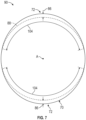
Figure 7 is another sectional view at the forward side of the thrust reverser opening. -
Figure 8 is a sectional view at the forward side of the thrust reverser opening. -
Figure 9 is another sectional view at the exit of the thrust reverser nozzle. -
Figure 1 schematically illustrates agas turbine engine 20. The examplegas turbine engine 20 is a turbofan that generally incorporates acore engine 25, afan section 22, acompressor section 24, acombustor section 26 and aturbine section 28. Thefan section 22 drives air along a bypass flow path B in a bypass duct defined within anacelle 30. Thecompressor section 24 drives air along a core flow path C into thecompressor section 24 for compression and communication into thecombustor section 26. In thecombustor section 26, the compressed air is mixed with fuel from afuel system 32 and ignited byigniter 34 to generate an exhaust gas flow that expands through theturbine section 28 and is exhaustedpast tail cone 36. - Although depicted as a turbofan turbine engine in the disclosed non-limiting embodiment, it should be understood that the concepts described herein are not limited to use with turbofans as the teachings may be applied to other types of turbine engines. Moreover, although turbine engines are described by way of example, other engine configurations such as internal combustion engines could be utilized and are within the contemplation of this disclosure.
- The
nacelle 30 includes anintake end 42 and anexhaust end 44. Athrust reversing nozzle 38 is disposed at theexhaust end 44. Thenozzle 38 defines an exhaust flow path between aninlet 46 and anexit 48. Thenozzle 38 is attached to theexhaust end 44 of thenacelle 30. - Referring to
Figure 2 , with continued reference toFigure 1 ,nozzle 38 includes opposingthrust reverser openings 50 that are covered by thrust reverserdoors 52 when in a closed position. In an open or deployed position, the thrust reverserdoors 52 uncover thethrust reverser openings 50 todirect flow 40 through thenozzle 38 forward towards a nose of the aircraft to provide faster deceleration. In the deployed position shown inFigure 2 , the opposing thrust reverseropenings 50 and the inner surface of thethrust reversing doors 52 form the path for theflow 40. Although the example openings 50 anddoors 52 are substantially the same, theopenings 50 anddoors 52 may be sized differently to provide different flow areas and remain with the contemplation and scope of this disclosure. - The area of the
openings 50 are defined between first andsecond arms doors 52 and by a cross-section through thenozzle 38 proximate aforward side 58 of each of theopenings 50. The inner cross-sectional area of thenozzle 38 at theforward side 58 of each of theopenings 50 further defines the flow area for theflow 40 when the thrust reverserdoors 52 are deployed. The nozzle geometry is balanced to provide sufficient area to match other engine operating conditions during forward aircraft operation and thrust reverser performance. - The
example nozzle 38 includes an increased cross-sectional area at an axial position corresponding with theforward side 58 of each of theopenings 50 to increase an effective area with thedoors 52 deployed. The inlet and exit areas remain unchanged. In one example embodiment, the inlet and exit areas are substantially circular. The localized increase in the cross-sectional area at theopenings 50 provides an increase in the effective flow area, without adjusting or changing other features of thenozzle 38, thereby maintaining desired performance during other engine operating conditions. - Referring to
Figure 3 with continued reference toFigure 2 , theexample inlet 46 andexit 48 are circular while the cross-section proximate theforward side 58 is offset to provide a local oval shape. Accordingly, in one disclosed example, an inner radius at each of theinlet 46 and theexit 48 is uniform about the central axis A to provide a circular cross-sectional area. An offset radius at theforward side 58 of each of theopposing openings 50 is increased at top and bottom circumferential positions to provide an oval cross-sectional flow area at anaxial distance 68 from theinlet 46. - Although the cross-section of the
inlet 46 andexit 48 are shown by way of example as being circular with a uniform radius, other shapes could be utilized including elliptical, oval and other irregular shapes and remain with the contemplation and scope of this disclosure. Moreover, although theexample nozzle 38 is shown as being symmetric about the axis A, theentire nozzle 38 or portions of thenozzle 38 may be asymmetric about the axis A and remain within the scope and contemplation of this disclosure. - Referring to
Figures 4, 5 and 6 with continued reference toFigure 3 , an innerperipheral surface 106 of thenozzle 38 within aplane 92 at theinlet 46 is of aconstant radius 60 about the axis A to define a circular flow area (Figure 4 ). The innerperipheral surface 108 of thenozzle 38 within theplane 94 at theexit 48 includes aconstant radius 62 about the axis A to define a circular flow area (Figure 6 ). - An inner
peripheral surface 110 within aplane 90 proximate theforward side 58 of each of theopposing openings 50 includes anoffset radius 64 that is larger than afirst radius 66 to define an oval-shaped flow area (Figure 5 ). Theexample offset radius 64 tapers from theradius 66 to a maximum offset radius located along a central plane 84 (Figure 5 ) transverse to the central axis A. The maximum radii are spaced apart a circumferentially as indicated at 74. In this example embodiment, the maximum offset radius is located at positions indicated at 72 that are spaced circumferentially apart 180 degrees. Moreover, the axial location of the maximum offsetradius 64 is shown as being proximate theforward side 58 of theopenings 50 within theplane 90. Theplane 90 is spaced theaxial distance 68 from theinlet 46. - In this example embodiment, the maximum offset radius positions 72 are disposed at the top center and bottom center positions. However, the maximum offset radius position may be tilted with respect to the
central plane 84 and remain within the contemplation and scope of this disclosure. - The increase in radius proximate the
forward side 58 is provided by a first taperedinner surface 76 between theinlet 46 and theplane 90 proximate theforward side 58. The taperedinner surface 76 is disposed at a first angle 78 (Figure 3 ). A second taperedinner surface 80 extends from theplane 90 proximate theforward side 58 to theexit 48. The second taperedinner surface 80 is disposed at a second angle 82 (Figure 3 ). Thesecond angle 82 is greater than thefirst angle 76 to provide for the transition from the elliptical cross-section to the circular cross-section at theexit 48. - Referring to
Figure 7 , with continued reference toFigures 3 and5 , an offset 86 is shown as compared to a circular area shown by the dashed line circle indicated at 88. The offset 86 provides for an increased area within thesolid outline 70 representing the inner surface of thenozzle 38 as compared to a circular area indicated by the dashedline 88. The offset 86 is disposed within offsetarc segments 104 at top and bottom portions of the inner surface. The offset 86 increases in a direction toward the top and bottom maximum offsetpositions 72 of the inner surface. - In one example disclosed embodiment, the cross-sectional area of the
plane 90 within the nozzle at theaxial distance 68 corresponding with theforward side 58 is between 1% and 10% greater than a cross-sectional area at the same axial location with a uniform radius about the central axis as represented by the dashedline circle 88. In another disclosed embodiment, the cross-sectional area is between 2% and 3% greater than cross-sectional area at the same axial location with a uniform radius about the central axis as represented by the dashedline circle 88. - In one example embodiment, the maximum increased offset
radius 64 is between 1% and 10% greater than the firstinner radius 66 outside of thethrust reverser openings 50 at a common axial location defined along thecentral plane 84. In another example embodiment, the maximum offsetradius 64 is between 2% and 3% greater than theinner radius 66 outside of thethrust reverser openings 50 at the common axial location defined along thecentral plane 84. - Referring to
Figures 8 and 9 , thethrust reverser doors 52 and the first andsecond side arms 54 define the inner surface of thenozzle 38 from theplane 90 to theexit 48. The inner surface of thethrust reverser doors 52 are therefore spaced from the axis A the same offsetradius 64 as is provided at theforward side 58. Theradius 66 is clocked 90 degrees from the offsetradius 64 and is defined by the inner surface of the first andsecond arms - Each of the thrust reverser doors include a
forward edge 96 and anaft edge 98. In the closed position theforward edge 98 includes the offsetinner radius 64 within theplane 90. Theaft edge 98 of thethrust reverser doors 52 defines a portion of the uniforminner radius 62 about the central axis A within theplane 94 at theexit 48. In the closed position, thethrust reverser doors 52 define anarc 100 of the inner peripheral surface of thenozzle 38 at theforward edge 96 and anarc 102 at theaft edge 98. Thearc 100 tapers from theforward edge 96 near theforward side 58 to thearc 102 within theplane 94 at theexit 48. - Although the aft edge of the
reverser doors 52 define a portion of theexit 48 in one disclosed example, theexit 48 may be defined separate from thereverser doors 52. Theexit 48 may be deposed axially aft of theaft edge 98 and include an uninterrupted periphery that is defined by static structures of thenozzle 38. - The radii defined by each of the
thrust reverser doors 52 tapers from the offsetradius 64 that is proximate theforward side 58 to the inner peripheral surface within theplane 94 at theexit 48. Theradius 66 is clocked 90 degrees from the offsetradius 64 defined by the first andsecond arms inner radius 66 within theplane 90 to theinner radius 62 disposed within theplane 94 at theexit 48. Theconstant uniform radius 62 about the axis A provides the circular cross-section at theexit 48. Although thethrust reverser doors 52 and the first andsecond side arms plane 90, they both taper to the commoninner radius 62 to provide the circular area within theplane 94 at thenozzle exit 48. - Accordingly, the
example nozzle 38 provides an increased thrust reverser flow area within a limited nozzle length without substantial changes to nozzle performance at other engine operating conditions. - An engine nacelle assembly according to an exemplary embodiment of this disclosure, among other possible things includes a
nacelle 30 that defines a flow path between anintake end 42 and anexhaust end 44, and anozzle 38 that is disposed at theexhaust end 44 of thenacelle 30 about a central axis. Thenozzle 38 includes opposingthrust reverser openings 50 and thrustreverser doors 52. A cross-sectional area transverse to the central axis proximate aforward side 58 of each of the opposingthrust reverser openings 50 is oval shaped with an offsetradius 64 within offsetarc segments 104 that are aligned with the opposingthrust reverser openings 50 and afirst radius 66 outside of the offsetarc segment 104. Thefirst radius 66 is less than the offsetradius 64. - In a further embodiment of the foregoing engine nacelle assembly, the offset
radius 64 at theforward side 58 of each of the opposingthrust reverser openings 50 includes a maximum offset that is disposed within a common plane transverse to the central axis. - In a further embodiment of any of the foregoing engine nacelle assemblies, the cross-sectional area that is proximate transverse to the central axis that is proximate the
forward side 58 is between 1% and 10% greater than a cross-sectional area at the same axial location with a uniform radius about the central axis. - In a further embodiment of any of the foregoing engine nacelle assemblies, the maximum offset is between 2% and 3% greater than the
first radius 66. - In a further embodiment of any of the foregoing engine nacelle assemblies, the
nozzle 38 includes aninlet 46 that is spaced axially apart from anexit 48 along the central axis and theforward side 58 is spaced a first axial distance from theinlet 46 and an inner surface of thenozzle 38 tapers at afirst angle 78 from theinlet 46 to theforward side 58 and tapers at asecond angle 82 from theforward side 58 to theexit 48. - In a further embodiment of any of the foregoing engine nacelle assemblies, the
first angle 78 is less than thesecond angle 82. - In a further embodiment of any of the foregoing, the engine nacelle assembly includes first and
second arms thrust reverser openings 50 and extend from an axial location that is common with theforward side 58 to theexit 48. The first andsecond arms inner periphery 108 at theexit 48. - In a further embodiment of any of the foregoing engine nacelle assemblies, the
inner periphery 108 at theexit 48 is uninterrupted. - In a further embodiment of any of the foregoing engine nacelle assemblies, the
thrust reverser doors 52 each include aforward edge 96 and anaft edge 98 and in a closed position theforward edge 96 includes an offset inner radius that is equal to the offsetinner radius 64 of theforward side 58 of a corresponding one of thethrust reverser openings 50. - In a further embodiment of any of the foregoing engine nacelle assemblies, the
aft edge 98 of thethrust reverser doors 52 defines a portion of theinner periphery 108 at theexit 48. - In a further embodiment of any of the foregoing engine nacelle assemblies, in a closed position, the
thrust reverser doors 52 define anarc 100/102 of the inner surface of thenozzle 38 that tapers from theforward side 58 toward theexit 48. - A thrust reverser for a turbine engine according to another exemplary embodiment of this disclosure, among other possible things includes a
nozzle 38 that includes aninlet 46 andexit 48 spaced axially apart along a central axis, opposingthrust reverser openings 50 and first andsecond side arms thrust reverser openings 50, and thrustreverser doors 52 that are movable between a closed position that covers a corresponding one of the opposingthrust reverser openings 50 and an open position uncovering the opposingthrust reverser openings 50. A cross-sectional area transverse to the central axis proximate aforward side 58 of each of the opposingthrust reverser openings 50 is oval shaped with an offsetradius 64 within offsetarc segments 104 that are aligned with the opposingthrust reverser openings 50 and afirst radius 66 outside of the offsetarc segment 104. Thefirst radius 66 is less than the offsetradius 64. - In a further embodiment of the foregoing thrust reverser for a turbine engine, the offset
radius 64 at theforward side 58 of the opposingthrust reverser openings 50 includes a maximum offset 86 and the maximum offset 86 of one of the opposingthrust reverser openings 50 is spaced 180 degrees apart from the other of the opposingthrust reverser openings 50. - In a further embodiment of any of the foregoing thrust reversers for a turbine engine, the maximum offset is between 1% and 10% greater than the
first radius 66. - In a further embodiment of any of the foregoing thrust reversers for a turbine engine, the maximum offset is between 2% and 3% greater than the
first radius 66. - In a further embodiment of any of the foregoing thrust reversers for a turbine engine, the
forward side 58 is spaced a firstaxial distance 68 from theinlet 46 and an inner surface of thenozzle 38 tapers at afirst angle 78 from theinlet 46 to theforward side 58 and tapers at asecond angle 82 from theforward side 58 to theexit 48. Thefirst angle 78 is less than thesecond angle 82. - In a further embodiment of any of the foregoing thrust reversers for a turbine engine, the
thrust reverser doors 52 each include aforward edge 96 and anaft edge 98 and in a closed position theforward edge 96 includes an offsetradius 64 equal to the offsetradius 64 of theforward side 58 of a corresponding one of thethrust reverser openings 50 and theaft edge 98 of thethrust reverser doors 52 and an aft portion of the first andsecond arms inner periphery 108 at theexit 48. - A turbine engine assembly according to another exemplary embodiment of this disclosure, among other possible things includes a
core engine 25, anacelle 30 that surrounds at least a portion of thecore engine 25 that defines a flow path between anintake end 42 and anexhaust end 44, and anozzle 38 that is disposed at theexhaust end 44 of thenacelle 30. Thenozzle 38 includes aninlet 46 andexit 48 spaced apart axially along a central axis, opposingthrust reverser openings 50, and thrustreverser doors 52 that are movable between a closed position that covers a corresponding one of the opposingthrust reverser openings 50 and an open position that uncovers the opposingthrust reverser openings 50. A cross-sectional area that is transverse to the central axis proximate aforward side 58 of each of the opposingthrust reverser openings 50 is oval shaped with an offsetradius 64 within offsetarc segments 104 that are aligned with the opposingthrust reverser openings 50 and afirst radius 66 outside of the offsetarc segment 104. Thefirst radius 66 is less than the offsetradius 64. - In a further embodiment of the foregoing thrust reverser for a turbine engine, the offset
radius 64 includes a maximum offset and the maximum offset of one of the opposingthrust reverser openings 50 is spaced 180 degrees apart from the other of the opposingthrust reverser openings 50. - In a further embodiment of any of the foregoing thrust reversers for a turbine engine, the maximum offset is between 1% and 10% greater than the
first radius 66. - Although an example embodiment has been disclosed, a worker of ordinary skill in this art would recognize that certain modifications would come within the scope of this disclosure. For that reason, the following claims should be studied to determine the scope and content of this disclosure.
Claims (15)
- An engine nacelle assembly comprising:a nacelle (30) defining a flow path between an intake end (42) and an exhaust end (44); anda nozzle (38) disposed at the exhaust end (44) of the nacelle (30) about a central axis (A), the nozzle (38) including opposing thrust reverser openings (50) and thrust reverser doors (52), wherein a cross-sectional area transverse to the central axis (A) proximate a forward side (58) of each of the opposing thrust reverser openings (50) is oval shaped with an offset radius (64) within offset arc segments (104) aligned with the opposing thrust reverser openings (50) and a first radius (66) outside of the offset arc segments (104), wherein the first radius (66) is less than the offset radius (64).
- The engine nacelle assembly as recited in claim 1, wherein the offset radius (64) at the forward side (58) of each of the opposing thrust reverser openings (50) includes a maximum offset (86) that is disposed within a common plane (84) transverse to the central axis (A), wherein the maximum offset (86) is optionally between 2% and 3% greater than the first radius (66).
- The engine nacelle assembly as recited in claim 1 or 2, wherein the cross-sectional area transverse to the central axis (A) proximate the forward side (58) is between 1% and 10% greater than a cross-sectional area at the same axial location with a uniform radius (66) about the central axis (A).
- The engine nacelle (30) assembly as recited in any preceding claim, wherein the nozzle (38) includes an inlet (46) spaced axially apart from an exit (48) along the central axis (A) and the forward side (58) is spaced a first axial distance (68) from the inlet (46) and an inner surface (76, 80) of the nozzle (38) tapers at a first angle (78) from the inlet (46) to the forward side (58) and tapers at a second angle (82) from the forward side (58) to the exit (48), wherein the first angle (78) is optionally less than the second angle (82).
- The engine nacelle assembly as recited in any preceding claim, including first and second arms (54, 56) disposed between the opposing thrust reverser openings (50) and extending from an axial location common with the forward side (58) to the exit (48), wherein the first and second arms (54, 56) define a portion of an inner periphery (108) at the exit (48), wherein the inner periphery (108) at the exit (48) is optionally uninterrupted.
- The engine nacelle assembly as recited in claim 5, wherein the thrust reverser doors (52) each include a forward edge (96) and an aft edge (98) and in a closed position the forward edge (96) includes an offset inner radius equal to the offset inner radius (64) of the forward side (58) of a corresponding one of the thrust reverser openings (50).
- The engine nacelle assembly as recited in claim 6, wherein the aft edge (98) of the thrust reverser doors (52) defines a portion of the inner periphery (108) at the exit (48).
- The engine nacelle (30) assembly as recited in claim 6 or 7, wherein in a closed position, the thrust reverser doors (52) define an arc (100, 102) of an inner surface (80) of the nozzle (38) that tapers from the forward side (58) toward the exit (48).
- A thrust reverser for a turbine engine (20) comprising:a nozzle (38) including an inlet (44) and exit (48) spaced axially apart along a central axis (A), opposing thrust reverser openings (50) and first and second side arms (54, 56) disposed on either side of each of the opposing thrust reverser openings (50); andthrust reverser doors (52) movable between a closed position covering a corresponding one of the opposing thrust reverser openings (50) and an open position uncovering the opposing thrust reverser openings (50), wherein a cross-sectional area transverse to the central axis (A) proximate a forward side (58) of each of the opposing thrust reverser openings (50) is oval shaped with an offset radius (64) within offset arc segments (104) aligned with the opposing thrust reverser openings (50) and a first radius (66) outside of the offset arc segment (104), the first radius (66) being less than the offset radius (64).
- The thrust reverser for a turbine engine as recited in claim 9, wherein the offset radius (64) at the forward side (58) of the opposing thrust reverser openings (50) includes a maximum offset (86) and the maximum offset (86) of one of the opposing thrust reverser openings (50) is spaced 180 degrees apart from the other of the opposing thrust reverser openings (50).
- The thrust reverser for a turbine engine as recited in claim 10, wherein the maximum offset (86) is between 1% and 10%, optionally between 2% and 3%, greater than the first radius (66).
- The thrust reverser for a turbine engine as recited in any of claims 9 to 11, wherein the forward side (58) is spaced (180) a first axial distance (68) from the inlet (44) and an inner surface of the nozzle (38) tapers at a first angle (78) from the inlet (44) to the forward side (58) and tapers at a second angle (82) from the forward side (58) to the exit (48), wherein the first angle (78) is less than the second angle (82).
- The thrust reverser for a turbine engine as recited in claim 12, wherein the thrust reverser doors (52) each include a forward edge (96) and an aft edge (98) and in a closed position the forward edge (96) includes an offset radius (64) equal to the offset radius (64) of the forward side (58) of a corresponding one of the thrust reverser openings (50) and the aft edge (98) of the thrust reverser doors (52) and an aft portion of the first and second arms (54) define a portion of an inner periphery (108) at the exit (48).
- A turbine engine assembly comprising:a core engine (25); andthe engine nacelle assembly of any of claims 1 to 8, wherein:the nacelle (30) surrounds at least a portion of the core engine (25);the nozzle (38) includes an or the inlet (46) and exit (48) spaced apart axially along the central axis (A); andthe thrust reverser doors (52) are movable between a closed position covering a corresponding one of the opposing thrust reverser openings (50) and an open position uncovering the opposing thrust reverser openings (50).
- The turbine engine assembly as recited in claim 14, wherein the offset radius (64) includes a maximum offset (86) and the maximum offset (86) of one of the opposing thrust reverser openings (50) is spaced 180 degrees apart from the other of the opposing thrust reverser openings (50), wherein the maximum offset (86) is optionally between 1% and 10% greater than the first radius (66).
Priority Applications (1)
| Application Number | Priority Date | Filing Date | Title |
|---|---|---|---|
| EP25208698.8A EP4729764A1 (en) | 2023-02-14 | 2024-02-13 | Gas turbine engine nozzle for thrust reverser |
Applications Claiming Priority (1)
| Application Number | Priority Date | Filing Date | Title |
|---|---|---|---|
| US18/109,428 US12000358B1 (en) | 2023-02-14 | 2023-02-14 | Gas turbine engine nozzle loft for thrust reverser |
Related Child Applications (1)
| Application Number | Title | Priority Date | Filing Date |
|---|---|---|---|
| EP25208698.8A Division EP4729764A1 (en) | 2023-02-14 | 2024-02-13 | Gas turbine engine nozzle for thrust reverser |
Publications (2)
| Publication Number | Publication Date |
|---|---|
| EP4417805A1 true EP4417805A1 (en) | 2024-08-21 |
| EP4417805B1 EP4417805B1 (en) | 2025-10-15 |
Family
ID=89940985
Family Applications (2)
| Application Number | Title | Priority Date | Filing Date |
|---|---|---|---|
| EP24157464.9A Active EP4417805B1 (en) | 2023-02-14 | 2024-02-13 | Gas turbine engine nozzle for thrust reverser |
| EP25208698.8A Pending EP4729764A1 (en) | 2023-02-14 | 2024-02-13 | Gas turbine engine nozzle for thrust reverser |
Family Applications After (1)
| Application Number | Title | Priority Date | Filing Date |
|---|---|---|---|
| EP25208698.8A Pending EP4729764A1 (en) | 2023-02-14 | 2024-02-13 | Gas turbine engine nozzle for thrust reverser |
Country Status (3)
| Country | Link |
|---|---|
| US (1) | US12000358B1 (en) |
| EP (2) | EP4417805B1 (en) |
| CA (1) | CA3224025A1 (en) |
Citations (3)
| Publication number | Priority date | Publication date | Assignee | Title |
|---|---|---|---|---|
| US2481330A (en) * | 1946-08-06 | 1949-09-06 | Gen Electric | Variable jet nozzle |
| FR2601077A1 (en) * | 1986-07-07 | 1988-01-08 | Hurel Dubois Avions | Gas-discharge structure for a jet engine, particularly for a bypass jet engine |
| US20140369829A1 (en) * | 2012-03-02 | 2014-12-18 | Aircelle | Flattened nacelle of a turbojet engine |
Family Cites Families (10)
| Publication number | Priority date | Publication date | Assignee | Title |
|---|---|---|---|---|
| FR2645911B1 (en) * | 1989-04-18 | 1991-06-07 | Snecma | HIGH DILUTION MOTOR WITH UPSTREAM BLOWER AND DOWNSTREAM BLOWER |
| US8091335B2 (en) | 2008-02-14 | 2012-01-10 | Spirit Aerosystems, Inc. | Swept fan ramp for pivot door thrust reverser |
| US8439305B2 (en) | 2009-06-09 | 2013-05-14 | Honeywell International Inc. | Non-handed thrust reverser for installation on handed aircraft gas turbine propulsion engines |
| FR2956162B1 (en) | 2010-02-08 | 2012-11-16 | Snecma | COLD FLOW TUYERE OF A TWO SEPARATE FLOW DOUBLE FLOW TURBOREACTOR INCORPORATING A GRILLED PUSH INVERTER |
| US9057286B2 (en) | 2010-03-30 | 2015-06-16 | United Technologies Corporation | Non-circular aft nacelle cowling geometry |
| US9631578B2 (en) * | 2013-02-22 | 2017-04-25 | United Technologies Corporation | Pivot thrust reverser surrounding inner surface of bypass duct |
| FR3006378B1 (en) | 2013-05-29 | 2015-05-15 | Aircelle Sa | TURBOREACTOR NACELLE COMPRISING A DOOR PUSH REVERSING DEVICE COMPRISING INSIDE FLANGES ON THE OPENING SIDES |
| DE102016100575A1 (en) * | 2016-01-14 | 2017-07-20 | Rolls-Royce Deutschland Ltd & Co Kg | Thrust reverser of a turbomachine |
| US10794327B2 (en) * | 2018-03-21 | 2020-10-06 | Honeywell International Inc. | Systems and methods for thrust reverser with temperature and fluid management |
| US11187187B2 (en) * | 2018-08-06 | 2021-11-30 | Rohr, Inc. | Thrust reverser |
-
2023
- 2023-02-14 US US18/109,428 patent/US12000358B1/en active Active
- 2023-12-20 CA CA3224025A patent/CA3224025A1/en active Pending
-
2024
- 2024-02-13 EP EP24157464.9A patent/EP4417805B1/en active Active
- 2024-02-13 EP EP25208698.8A patent/EP4729764A1/en active Pending
Patent Citations (3)
| Publication number | Priority date | Publication date | Assignee | Title |
|---|---|---|---|---|
| US2481330A (en) * | 1946-08-06 | 1949-09-06 | Gen Electric | Variable jet nozzle |
| FR2601077A1 (en) * | 1986-07-07 | 1988-01-08 | Hurel Dubois Avions | Gas-discharge structure for a jet engine, particularly for a bypass jet engine |
| US20140369829A1 (en) * | 2012-03-02 | 2014-12-18 | Aircelle | Flattened nacelle of a turbojet engine |
Also Published As
| Publication number | Publication date |
|---|---|
| CA3224025A1 (en) | 2025-04-17 |
| EP4729764A1 (en) | 2026-04-22 |
| EP4417805B1 (en) | 2025-10-15 |
| US12000358B1 (en) | 2024-06-04 |
Similar Documents
| Publication | Publication Date | Title |
|---|---|---|
| JP4949154B2 (en) | Gas exhaust nozzle of bypass turbomachine with exhaust cross section or throat cross section that can be changed by moving secondary cowl | |
| EP1430212B1 (en) | Converging nozzle thrust reverser | |
| US8662417B2 (en) | Gas turbine engine fan variable area nozzle with swivable insert system | |
| US9494084B2 (en) | Gas turbine engine with fan variable area nozzle for low fan pressure ratio | |
| JP4658618B2 (en) | Branch outlet guide vane | |
| EP2028359A2 (en) | Gas turbine engine with axial movable fan variable area nozzle | |
| US20120222397A1 (en) | Gas turbine engine with low fan pressure ratio | |
| EP2863038B1 (en) | Thrust reverser fan ramp with blocker door pocket | |
| US20110120136A1 (en) | Method of operating a turbofan engine cowl assembly | |
| US20130149112A1 (en) | Gas turbine engine with fan variable area nozzle | |
| EP4148246B1 (en) | Aircraft propulsion system with variable area inlet | |
| US7673442B2 (en) | Turbofan engine cowl assembly | |
| US20130149111A1 (en) | Gas turbine engine with fan variable area nozzle for low fan pressure ratio | |
| US20130149099A1 (en) | Gas turbine engine with fan variable area nozzle to reduce fan instability | |
| US8256225B2 (en) | Gas turbine engine with a variable exit area fan nozzle, nacelle assembly of such a engine, and corresponding operating method | |
| JP2013519032A (en) | Secondary air nozzle of a two-flow jet engine with separated flow, including a grid thrust reverser | |
| EP2963276B1 (en) | Compact nacelle with contoured fan nozzle | |
| EP4242445B1 (en) | Variable area nozzle assembly and method for operating a variable area nozzle assembly | |
| EP4417805B1 (en) | Gas turbine engine nozzle for thrust reverser | |
| EP3249203B1 (en) | Aircraft gas turbine engine nacelle | |
| EP4108574B1 (en) | Aircraft propulsion system with variable area inlet | |
| EP4198292B1 (en) | Variable area nozzle assembly and method for operating same | |
| EP4497936A2 (en) | Aircraft propulsion system with variable area inlet assembly | |
| US11713730B2 (en) | Convergent-divergent flap pair for a variable-geometry turbojet engine nozzle comprising cooling air circulation ducts connected through contact surfaces | |
| CN121399360A (en) | A turbojet engine aft body comprising a stationary cowl provided with a window for regulating the flow of fluid and a rotationally mobile cowl |
Legal Events
| Date | Code | Title | Description |
|---|---|---|---|
| PUAI | Public reference made under article 153(3) epc to a published international application that has entered the european phase |
Free format text: ORIGINAL CODE: 0009012 |
|
| STAA | Information on the status of an ep patent application or granted ep patent |
Free format text: STATUS: THE APPLICATION HAS BEEN PUBLISHED |
|
| AK | Designated contracting states |
Kind code of ref document: A1 Designated state(s): AL AT BE BG CH CY CZ DE DK EE ES FI FR GB GR HR HU IE IS IT LI LT LU LV MC ME MK MT NL NO PL PT RO RS SE SI SK SM TR |
|
| STAA | Information on the status of an ep patent application or granted ep patent |
Free format text: STATUS: REQUEST FOR EXAMINATION WAS MADE |
|
| 17P | Request for examination filed |
Effective date: 20250218 |
|
| GRAP | Despatch of communication of intention to grant a patent |
Free format text: ORIGINAL CODE: EPIDOSNIGR1 |
|
| STAA | Information on the status of an ep patent application or granted ep patent |
Free format text: STATUS: GRANT OF PATENT IS INTENDED |
|
| INTG | Intention to grant announced |
Effective date: 20250506 |
|
| GRAS | Grant fee paid |
Free format text: ORIGINAL CODE: EPIDOSNIGR3 |
|
| GRAA | (expected) grant |
Free format text: ORIGINAL CODE: 0009210 |
|
| STAA | Information on the status of an ep patent application or granted ep patent |
Free format text: STATUS: THE PATENT HAS BEEN GRANTED |
|
| AK | Designated contracting states |
Kind code of ref document: B1 Designated state(s): AL AT BE BG CH CY CZ DE DK EE ES FI FR GB GR HR HU IE IS IT LI LT LU LV MC ME MK MT NL NO PL PT RO RS SE SI SK SM TR |
|
| REG | Reference to a national code |
Ref country code: GB Ref legal event code: FG4D Ref country code: CH Ref legal event code: F10 Free format text: ST27 STATUS EVENT CODE: U-0-0-F10-F00 (AS PROVIDED BY THE NATIONAL OFFICE) Effective date: 20251015 |
|
| REG | Reference to a national code |
Ref country code: IE Ref legal event code: FG4D |
|
| REG | Reference to a national code |
Ref country code: DE Ref legal event code: R096 Ref document number: 602024000884 Country of ref document: DE |
|
| REG | Reference to a national code |
Ref country code: NL Ref legal event code: MP Effective date: 20251015 |
|
| REG | Reference to a national code |
Ref country code: AT Ref legal event code: MK05 Ref document number: 1847148 Country of ref document: AT Kind code of ref document: T Effective date: 20251015 |
|
| PG25 | Lapsed in a contracting state [announced via postgrant information from national office to epo] |
Ref country code: NL Free format text: LAPSE BECAUSE OF FAILURE TO SUBMIT A TRANSLATION OF THE DESCRIPTION OR TO PAY THE FEE WITHIN THE PRESCRIBED TIME-LIMIT Effective date: 20251015 |
|
| PG25 | Lapsed in a contracting state [announced via postgrant information from national office to epo] |
Ref country code: ES Free format text: LAPSE BECAUSE OF FAILURE TO SUBMIT A TRANSLATION OF THE DESCRIPTION OR TO PAY THE FEE WITHIN THE PRESCRIBED TIME-LIMIT Effective date: 20251015 |
|
| REG | Reference to a national code |
Ref country code: LT Ref legal event code: MG9D |
|
| PG25 | Lapsed in a contracting state [announced via postgrant information from national office to epo] |
Ref country code: NO Free format text: LAPSE BECAUSE OF FAILURE TO SUBMIT A TRANSLATION OF THE DESCRIPTION OR TO PAY THE FEE WITHIN THE PRESCRIBED TIME-LIMIT Effective date: 20260115 |
|
| PGFP | Annual fee paid to national office [announced via postgrant information from national office to epo] |
Ref country code: DE Payment date: 20260121 Year of fee payment: 3 |
|
| PG25 | Lapsed in a contracting state [announced via postgrant information from national office to epo] |
Ref country code: FI Free format text: LAPSE BECAUSE OF FAILURE TO SUBMIT A TRANSLATION OF THE DESCRIPTION OR TO PAY THE FEE WITHIN THE PRESCRIBED TIME-LIMIT Effective date: 20251015 Ref country code: AT Free format text: LAPSE BECAUSE OF FAILURE TO SUBMIT A TRANSLATION OF THE DESCRIPTION OR TO PAY THE FEE WITHIN THE PRESCRIBED TIME-LIMIT Effective date: 20251015 Ref country code: HR Free format text: LAPSE BECAUSE OF FAILURE TO SUBMIT A TRANSLATION OF THE DESCRIPTION OR TO PAY THE FEE WITHIN THE PRESCRIBED TIME-LIMIT Effective date: 20251015 |
|
| PG25 | Lapsed in a contracting state [announced via postgrant information from national office to epo] |
Ref country code: RS Free format text: LAPSE BECAUSE OF FAILURE TO SUBMIT A TRANSLATION OF THE DESCRIPTION OR TO PAY THE FEE WITHIN THE PRESCRIBED TIME-LIMIT Effective date: 20260115 |
|
| PG25 | Lapsed in a contracting state [announced via postgrant information from national office to epo] |
Ref country code: IS Free format text: LAPSE BECAUSE OF FAILURE TO SUBMIT A TRANSLATION OF THE DESCRIPTION OR TO PAY THE FEE WITHIN THE PRESCRIBED TIME-LIMIT Effective date: 20260215 |
|
| PGFP | Annual fee paid to national office [announced via postgrant information from national office to epo] |
Ref country code: FR Payment date: 20260121 Year of fee payment: 3 |
|
| PG25 | Lapsed in a contracting state [announced via postgrant information from national office to epo] |
Ref country code: PT Free format text: LAPSE BECAUSE OF FAILURE TO SUBMIT A TRANSLATION OF THE DESCRIPTION OR TO PAY THE FEE WITHIN THE PRESCRIBED TIME-LIMIT Effective date: 20260216 |
|
| PG25 | Lapsed in a contracting state [announced via postgrant information from national office to epo] |
Ref country code: PL Free format text: LAPSE BECAUSE OF FAILURE TO SUBMIT A TRANSLATION OF THE DESCRIPTION OR TO PAY THE FEE WITHIN THE PRESCRIBED TIME-LIMIT Effective date: 20251015 |
|
| PG25 | Lapsed in a contracting state [announced via postgrant information from national office to epo] |
Ref country code: LV Free format text: LAPSE BECAUSE OF FAILURE TO SUBMIT A TRANSLATION OF THE DESCRIPTION OR TO PAY THE FEE WITHIN THE PRESCRIBED TIME-LIMIT Effective date: 20251015 |
|
| PG25 | Lapsed in a contracting state [announced via postgrant information from national office to epo] |
Ref country code: BG Free format text: LAPSE BECAUSE OF FAILURE TO SUBMIT A TRANSLATION OF THE DESCRIPTION OR TO PAY THE FEE WITHIN THE PRESCRIBED TIME-LIMIT Effective date: 20251015 |
|
| PG25 | Lapsed in a contracting state [announced via postgrant information from national office to epo] |
Ref country code: LT Free format text: LAPSE BECAUSE OF FAILURE TO SUBMIT A TRANSLATION OF THE DESCRIPTION OR TO PAY THE FEE WITHIN THE PRESCRIBED TIME-LIMIT Effective date: 20251015 |
|
| PG25 | Lapsed in a contracting state [announced via postgrant information from national office to epo] |
Ref country code: SM Free format text: LAPSE BECAUSE OF FAILURE TO SUBMIT A TRANSLATION OF THE DESCRIPTION OR TO PAY THE FEE WITHIN THE PRESCRIBED TIME-LIMIT Effective date: 20251015 |
|
| PG25 | Lapsed in a contracting state [announced via postgrant information from national office to epo] |
Ref country code: DK Free format text: LAPSE BECAUSE OF FAILURE TO SUBMIT A TRANSLATION OF THE DESCRIPTION OR TO PAY THE FEE WITHIN THE PRESCRIBED TIME-LIMIT Effective date: 20251015 |
|
| PG25 | Lapsed in a contracting state [announced via postgrant information from national office to epo] |
Ref country code: IT Free format text: LAPSE BECAUSE OF FAILURE TO SUBMIT A TRANSLATION OF THE DESCRIPTION OR TO PAY THE FEE WITHIN THE PRESCRIBED TIME-LIMIT Effective date: 20251015 |
|
| PG25 | Lapsed in a contracting state [announced via postgrant information from national office to epo] |
Ref country code: EE Free format text: LAPSE BECAUSE OF FAILURE TO SUBMIT A TRANSLATION OF THE DESCRIPTION OR TO PAY THE FEE WITHIN THE PRESCRIBED TIME-LIMIT Effective date: 20251015 |
|
| PG25 | Lapsed in a contracting state [announced via postgrant information from national office to epo] |
Ref country code: CZ Free format text: LAPSE BECAUSE OF FAILURE TO SUBMIT A TRANSLATION OF THE DESCRIPTION OR TO PAY THE FEE WITHIN THE PRESCRIBED TIME-LIMIT Effective date: 20251015 |
|
| PG25 | Lapsed in a contracting state [announced via postgrant information from national office to epo] |
Ref country code: SK Free format text: LAPSE BECAUSE OF FAILURE TO SUBMIT A TRANSLATION OF THE DESCRIPTION OR TO PAY THE FEE WITHIN THE PRESCRIBED TIME-LIMIT Effective date: 20251015 |
|
| PG25 | Lapsed in a contracting state [announced via postgrant information from national office to epo] |
Ref country code: SE Free format text: LAPSE BECAUSE OF FAILURE TO SUBMIT A TRANSLATION OF THE DESCRIPTION OR TO PAY THE FEE WITHIN THE PRESCRIBED TIME-LIMIT Effective date: 20251015 |