EP4417795A1 - Gas turbine engine with bleed diffuser baffles - Google Patents
Gas turbine engine with bleed diffuser baffles Download PDFInfo
- Publication number
- EP4417795A1 EP4417795A1 EP24158183.4A EP24158183A EP4417795A1 EP 4417795 A1 EP4417795 A1 EP 4417795A1 EP 24158183 A EP24158183 A EP 24158183A EP 4417795 A1 EP4417795 A1 EP 4417795A1
- Authority
- EP
- European Patent Office
- Prior art keywords
- bleed
- compressor
- gas turbine
- turbine engine
- holes
- Prior art date
- Legal status (The legal status is an assumption and is not a legal conclusion. Google has not performed a legal analysis and makes no representation as to the accuracy of the status listed.)
- Pending
Links
Images


Classifications
-
- F—MECHANICAL ENGINEERING; LIGHTING; HEATING; WEAPONS; BLASTING
- F02—COMBUSTION ENGINES; HOT-GAS OR COMBUSTION-PRODUCT ENGINE PLANTS
- F02C—GAS-TURBINE PLANTS; AIR INTAKES FOR JET-PROPULSION PLANTS; CONTROLLING FUEL SUPPLY IN AIR-BREATHING JET-PROPULSION PLANTS
- F02C6/00—Plural gas-turbine plants; Combinations of gas-turbine plants with other apparatus; Adaptations of gas-turbine plants for special use
- F02C6/04—Gas-turbine plants providing heated or pressurised working fluid for other apparatus, e.g. without mechanical power output
- F02C6/06—Gas-turbine plants providing heated or pressurised working fluid for other apparatus, e.g. without mechanical power output providing compressed gas
- F02C6/08—Gas-turbine plants providing heated or pressurised working fluid for other apparatus, e.g. without mechanical power output providing compressed gas the gas being bled from the gas-turbine compressor
-
- F—MECHANICAL ENGINEERING; LIGHTING; HEATING; WEAPONS; BLASTING
- F01—MACHINES OR ENGINES IN GENERAL; ENGINE PLANTS IN GENERAL; STEAM ENGINES
- F01D—NON-POSITIVE DISPLACEMENT MACHINES OR ENGINES, e.g. STEAM TURBINES
- F01D9/00—Stators
- F01D9/02—Nozzles; Nozzle boxes; Stator blades; Guide conduits, e.g. individual nozzles
-
- F—MECHANICAL ENGINEERING; LIGHTING; HEATING; WEAPONS; BLASTING
- F05—INDEXING SCHEMES RELATING TO ENGINES OR PUMPS IN VARIOUS SUBCLASSES OF CLASSES F01-F04
- F05D—INDEXING SCHEME FOR ASPECTS RELATING TO NON-POSITIVE-DISPLACEMENT MACHINES OR ENGINES, GAS-TURBINES OR JET-PROPULSION PLANTS
- F05D2220/00—Application
- F05D2220/30—Application in turbines
- F05D2220/32—Application in turbines in gas turbines
- F05D2220/323—Application in turbines in gas turbines for aircraft propulsion, e.g. jet engines
-
- F—MECHANICAL ENGINEERING; LIGHTING; HEATING; WEAPONS; BLASTING
- F05—INDEXING SCHEMES RELATING TO ENGINES OR PUMPS IN VARIOUS SUBCLASSES OF CLASSES F01-F04
- F05D—INDEXING SCHEME FOR ASPECTS RELATING TO NON-POSITIVE-DISPLACEMENT MACHINES OR ENGINES, GAS-TURBINES OR JET-PROPULSION PLANTS
- F05D2240/00—Components
- F05D2240/10—Stators
- F05D2240/12—Fluid guiding means, e.g. vanes
- F05D2240/126—Baffles or ribs
-
- F—MECHANICAL ENGINEERING; LIGHTING; HEATING; WEAPONS; BLASTING
- F05—INDEXING SCHEMES RELATING TO ENGINES OR PUMPS IN VARIOUS SUBCLASSES OF CLASSES F01-F04
- F05D—INDEXING SCHEME FOR ASPECTS RELATING TO NON-POSITIVE-DISPLACEMENT MACHINES OR ENGINES, GAS-TURBINES OR JET-PROPULSION PLANTS
- F05D2260/00—Function
- F05D2260/60—Fluid transfer
Definitions
- This application relates to baffles to improve the bleeding of compressor air from a gas turbine engine.
- Gas turbine engines typically include a fan delivering air into a bypass duct as propulsion air. Air is also delivered into a compressor. The compressed air is delivered into a combustor where it is mixed with fuel and ignited. Products of this combustion pass downstream over turbine rotors driving them to rotate. The turbine rotors in turn drive the compressor and fan rotors.
- bleed compressed air from the compressor section for various uses on an associated aircraft.
- a bleed system is utilized that bleeds air from a lower pressure location in the compressor section and also from a higher pressure location. Controls and valving select which of these air supplies is sent to an aircraft cabin air conditioning system.
- the air is bled from the higher-pressure section, and at higher power operation the air is bled from a lower pressure section of the compressor.
- Examples of the higher power operation include takeoff whereas as the lower power operation include at ground idle. This selective use is done to avoid using air that is over-pressurized and at excessively high temperature for the end use.
- bleed ports are packaged into each of these locations (e.g., higher-pressure section, lower pressure section). Further, there are challenges in maintaining adequate engine stability margins while operating these bleed systems.
- a gas turbine engine in a featured embodiment, includes a compressor section having a downstream most location and more upstream locations.
- a compressor housing surrounds the compressor rotors.
- a combustor is downstream of the compressor and a turbine section is downstream of the combustor.
- At least one bleed inlet passage bleeds air compressed from the compressor section, and delivers the air for use on an associated aircraft.
- a baffle plate is intermediate the at least one bleed inlet passage and a bleed exit port from the gas turbine engine.
- the baffle plate has a plurality of holes for allowing the air to flow from the bleed inlet passage to the bleed exit port, with an area of the holes increasing from a location adjacent the at least one bleed inlet passage and in a circumferential direction away from the at least one bleed inlet passage.
- the bleed inlet passage associated with the lower pressure location extends through a housing of the compressor section.
- the higher pressure location is downstream of the downstream most location in the compressor section, with the bleed inlet passage being a downstream end of a compressor diffuser.
- the baffle plate associated with the higher pressure location is attached to the compressor diffuser.
- the baffle plate at the lower pressure location extends circumferentially and is cylindrical with the holes extending with at least a component in a radially outward direction through the cylindrical section to the bleed exit port.
- the baffle plate is at the higher pressure location, with the holes extending with at least a component in an axial direction through the baffle plate to the bleed outlet line.
- the baffle plate at the higher pressure location is generally circular, with the holes extending with at least a component in an axial direction through the baffle plate to the bleed exit port.
- each of the bleed exit ports are to be connected to a use through a valve having an electric control to select between the two bleed exit ports lines to connect to the use.
- the use is a cabin air supply system for the associated aircraft.
- the increase in the area of the holes is achieved by increasing the size of the holes.
- the increase in the area of the holes is achieved by increasing the quantity of the holes.
- an aircraft air supply system in another featured embodiment, includes a gas turbine engine including a compressor section having a downstream most location and more upstream locations.
- a compressor housing surrounds compressor rotors, a combustor downstream of the compressor and a turbine section downstream of the combustor.
- At least one bleed inlet passage bleeds air compressed in the compressor section, and delivers the air for use on an associated aircraft.
- a baffle plate is intermediate the at least one bleed inlet passage and a bleed exit port from the gas turbine engine.
- the baffle plate has a plurality of holes for allowing the air to flow from the bleed inlet passage to the bleed exit port, with an area of the holes increasing from a location adjacent the at least one bleed exit port and in a circumferential direction away from the at least one bleed exit port.
- the bleed exit port is to be connected to the use.
- each of the bleed exit port is to be connected to the use through a valve having an electric control to select between the two bleed exit ports to connect to the use.
- the use is a cabin air supply system for the associated aircraft.
- the bleed inlet passage associated with the lower pressure location extends through a housing of the compressor section.
- the higher pressure location is downstream of the downstream most location in the compressor section, with the bleed inlet passage being a downstream end of a compressor diffuser.
- the baffle plate at the lower pressure location extends circumferentially and is cylindrical with the holes extending with at least a component in a radially outward direction through the cylindrical section to the bleed outlet line.
- the baffle plate is at the higher pressure location, with the holes extending with at least a component in an axial direction through the baffle plate to the bleed outlet line.
- the baffle plate is generally thin and with the holes extending with at least a component in an axial direction through the baffle plate to the bleed exit port.
- an aircraft in another featured embodiment, includes an aircraft body including a gas turbine engine including a compressor section having a downstream most location and more upstream locations.
- a compressor housing surrounds compressor rotors, a combustor downstream of the compressor and a turbine section downstream of the combustor.
- At least one bleed inlet passage bleeds air compressed in the compressor section, and delivers the air for use on an associated aircraft.
- a baffle plate is intermediate the at least one bleed inlet passage and a bleed exit port from the gas turbine engine.
- the baffle plate has a plurality of holes for allowing the air to flow from the bleed inlet passage to the bleed exit port connection, with an area of the holes increasing from a location adjacent the at least one bleed exit port and in a circumferential direction away from the at least one bleed exit port.
- the bleed exit port is to be connected to the use.
- Each of the bleed exit port is to be connected to the use through a valve having an electric control to select between the two bleed exit port to connect to the use.
- the use is a cabin air supply system for the associated aircraft.
- the present disclosure may include any one or more of the individual features disclosed above and/or below alone or in any combination thereof.
- FIG. 1 schematically illustrates a gas turbine engine 20.
- the gas turbine engine 20 is disclosed herein as a two-spool turbofan that generally incorporates a fan section 22, a compressor section 24, a combustor section 26 and a turbine section 28.
- the fan section 22 may include a single-stage fan 42 having a plurality of fan blades 43.
- the fan blades 43 may have a fixed stagger angle or may have a variable pitch to direct incoming airflow from an engine inlet.
- the fan 42 drives air along a bypass flow path B in a bypass duct 13 defined within a housing 15 such as a fan case or nacelle, and also drives air along a core flow path C for compression and communication into the combustor section 26 then expansion through the turbine section 28.
- a splitter 29 aft of the fan 42 divides the air between the bypass flow path B and the core flow path C.
- the housing 15 may surround the fan 42 to establish an outer diameter of the bypass duct 13.
- the splitter 29 may establish an inner diameter of the bypass duct 13.
- the exemplary engine 20 generally includes a low speed spool 30 and a high speed spool 32 mounted for rotation about an engine central longitudinal axis A relative to an engine static structure 36 via several bearing systems 38. It should be understood that various bearing systems 38 at various locations may alternatively or additionally be provided, and the location of bearing systems 38 may be varied as appropriate to the application.
- the low speed spool 30 generally includes an inner shaft 40 that interconnects, a first (or low) pressure compressor 44 and a first (or low) pressure turbine 46.
- the inner shaft 40 is connected to the fan 42 through a speed change mechanism, which in the exemplary gas turbine engine 20 is illustrated as a geared architecture 48 to drive the fan 42 at a lower speed than the low speed spool 30.
- the inner shaft 40 may interconnect the low pressure compressor 44 and low pressure turbine 46 such that the low pressure compressor 44 and low pressure turbine 46 are rotatable at a common speed and in a common direction.
- the low pressure turbine 46 drives both the fan 42 and low pressure compressor 44 through the geared architecture 48 such that the fan 42 and low pressure compressor 44 are rotatable at a common speed.
- the high speed spool 32 includes an outer shaft 50 that interconnects a second (or high) pressure compressor 52 and a second (or high) pressure turbine 54.
- a combustor 56 is arranged in the exemplary gas turbine 20 between the high pressure compressor 52 and the high pressure turbine 54.
- a mid-turbine frame 57 of the engine static structure 36 may be arranged generally between the high pressure turbine 54 and the low pressure turbine 46.
- the mid-turbine frame 57 further supports bearing systems 38 in the turbine section 28.
- the inner shaft 40 and the outer shaft 50 are concentric and rotate via bearing systems 38 about the engine central longitudinal axis A which is collinear with their longitudinal axes.
- the shafts may co-rotate or counter-rotate.
- Airflow in the core flow path C is compressed by the low pressure compressor 44 then the high pressure compressor 52, mixed and burned with fuel in the combustor 56, then expanded through the high pressure turbine 54 and low pressure turbine 46.
- the mid-turbine frame 57 includes airfoils 59 which are in the core flow path C.
- the turbines 46, 54 rotationally drive the respective low speed spool 30 and high speed spool 32 in response to the expansion.
- gear system 48 may be located aft of the low pressure compressor, or aft of the combustor section 26 or even aft of turbine section 28, and fan 42 may be positioned forward or aft of the location of gear system 48.
- the fan 42 may have at least 10 fan blades 43 but no more than 20 or 24 fan blades 43. In examples, the fan 42 may have between 12 and 18 fan blades 43, such as 14 fan blades 43.
- An exemplary fan size measurement is a maximum radius between the tips of the fan blades 43 and the engine central longitudinal axis A. The maximum radius of the fan blades 43 can be at least 40 inches, or more narrowly no more than 75 inches. For example, the maximum radius of the fan blades 43 can be between 45 inches and 60 inches, such as between 50 inches and 55 inches.
- Another exemplary fan size measurement is a hub radius, which is defined as distance between a hub of the fan 42 at a location of the leading edges of the fan blades 43 and the engine central longitudinal axis A.
- the fan blades 43 may establish a fan hub-to-tip ratio, which is defined as a ratio of the hub radius divided by the maximum radius of the fan 42.
- the fan hub-to-tip ratio can be less than or equal to 0.35, or more narrowly greater than or equal to 0.20, such as between 0.25 and 0.30.
- the combination of fan blade counts and fan hub-to-tip ratios disclosed herein can provide the engine 20 with a relatively compact fan arrangement.
- the low pressure compressor 44, high pressure compressor 52, high pressure turbine 54 and low pressure turbine 46 each include one or more stages having a row of rotatable airfoils. Each stage may include a row of vanes adjacent the rotatable airfoils.
- the rotatable airfoils are schematically indicated at 47, and the vanes are schematically indicated at 49.
- the low pressure compressor 44 and low pressure turbine 46 can include an equal number of stages.
- the engine 20 can include a three-stage low pressure compressor 44, an eight-stage high pressure compressor 52, a two-stage high pressure turbine 54, and a three-stage low pressure turbine 46 to provide a total of sixteen stages.
- the low pressure compressor 44 includes a different (e.g., greater) number of stages than the low pressure turbine 46.
- the engine 20 can include a five-stage low pressure compressor 44, a nine-stage high pressure compressor 52, a two-stage high pressure turbine 54, and a four-stage low pressure turbine 46 to provide a total of twenty stages.
- the engine 20 includes a four-stage low pressure compressor 44, a nine-stage high pressure compressor 52, a two-stage high pressure turbine 54, and a three-stage low pressure turbine 46 to provide a total of eighteen stages. It should be understood that the engine 20 can incorporate other compressor and turbine stage counts, including any combination of stages disclosed herein.
- the engine 20 may be a high-bypass geared aircraft engine.
- the bypass ratio can be greater than or equal to 10.0 and less than or equal to about 18.0, or more narrowly can be less than or equal to 16.0.
- the geared architecture 48 may be an epicyclic gear train, such as a planetary gear system or a star gear system.
- the epicyclic gear train may include a sun gear, a ring gear, a plurality of intermediate gears meshing with the sun gear and ring gear, and a carrier that supports the intermediate gears.
- the sun gear may provide an input to the gear train.
- the ring gear (e.g., star gear system) or carrier (e.g., planetary gear system) may provide an output of the gear train to drive the fan 42.
- a gear reduction ratio may be greater than or equal to 2.3, or more narrowly greater than or equal to 3.0, and in some embodiments the gear reduction ratio is greater than or equal to 3.4.
- the gear reduction ratio may be less than or equal to 4.0.
- the fan diameter is significantly larger than that of the low pressure compressor 44.
- the low pressure turbine 46 can have a pressure ratio that is greater than or equal to 8.0 and in some embodiments is greater than or equal to 10.0.
- the low pressure turbine pressure ratio can be less than or equal to 13.0, or more narrowly less than or equal to 12.0.
- Low pressure turbine 46 pressure ratio is pressure measured prior to an inlet of low pressure turbine 46 as related to the pressure at the outlet of the low pressure turbine 46 prior to an exhaust nozzle. It should be understood, however, that the above parameters are only exemplary of one embodiment of a geared architecture engine and that the present invention is applicable to other gas turbine engines including direct drive turbofans. All of these parameters are measured at the cruise condition described below.
- the fan section 22 of the engine 20 is designed for a particular flight condition -- typically cruise at about 0.8 Mach and about 35,000 feet (10,668 meters).
- the flight condition of 0.8 Mach and 35,000 ft (10,668 meters), with the engine at its best fuel consumption - also known as "bucket cruise Thrust Specific Fuel Consumption ('TSFC')" - is the industry standard parameter of lbm of fuel being burned divided by lbf of thrust the engine produces at that minimum point.
- 'TSFC' Thrust Specific Fuel Consumption
- Fan pressure ratio is the pressure ratio across the fan blade 43 alone, without a Fan Exit Guide Vane (“FEGV”) system.
- a distance is established in a radial direction between the inner and outer diameters of the bypass duct 13 at an axial position corresponding to a leading edge of the splitter 29 relative to the engine central longitudinal axis A.
- the fan pressure ratio is a spanwise average of the pressure ratios measured across the fan blade 43 alone over radial positions corresponding to the distance.
- the fan pressure ratio can be less than or equal to 1.45, or more narrowly greater than or equal to 1.25, such as between 1.30 and 1.40.
- “Corrected fan tip speed” is the actual fan tip speed in ft/sec divided by an industry standard temperature correction of [(Tram °R) / (518.7 °R)] 0.5 .
- the corrected fan tip speed can be less than or equal to 1150.0 ft / second (350.5 meters/second), and can be greater than or equal to 1000.0 ft / second (304.8 meters/second).
- the fan 42, low pressure compressor 44 and high pressure compressor 52 can provide different amounts of compression of the incoming airflow that is delivered downstream to the turbine section 28 and cooperate to establish an overall pressure ratio (OPR).
- OPR is a product of the fan pressure ratio across a root (i.e., 0% span) of the fan blade 43 alone, a pressure ratio across the low pressure compressor 44 and a pressure ratio across the high pressure compressor 52.
- the pressure ratio of the low pressure compressor 44 is measured as the pressure at the exit of the low pressure compressor 44 divided by the pressure at the inlet of the low pressure compressor 44.
- a sum of the pressure ratio of the low pressure compressor 44 and the fan pressure ratio is between 3.0 and 6.0, or more narrowly is between 4.0 and 5.5.
- the pressure ratio of the high pressure compressor ratio 52 is measured as the pressure at the exit of the high pressure compressor 52 divided by the pressure at the inlet of the high pressure compressor 52.
- the pressure ratio of the high pressure compressor 52 is between 9.0 and 12.0, or more narrowly is between 10.0 and 11.5.
- the OPR can be equal to or greater than 45.0, and can be less than or equal to 70.0, such as between 50.0 and 60.0.
- the overall and compressor pressure ratios disclosed herein are measured at the cruise condition described above, and can be utilized in two-spool architectures such as the engine 20 as well as three-spool engine architectures.
- the engine 20 establishes a turbine entry temperature (TET).
- TET turbine entry temperature
- the TET is defined as a maximum temperature of combustion products communicated to an inlet of the turbine section 28 at a maximum takeoff (MTO) condition.
- MTO maximum takeoff
- the inlet is established at the leading edges of the axially forwardmost row of airfoils of the turbine section 28, and MTO is measured at maximum thrust of the engine 20 at static sea-level and 86 degrees Fahrenheit (°F).
- the TET may be greater than or equal to 2700.0 °F, or more narrowly less than or equal to 3500.0 °F, such as between 2750.0 °F and 3350.0 °F.
- the relatively high TET can be utilized in combination with the other techniques disclosed herein to provide a compact turbine arrangement.
- the engine 20 establishes an exhaust gas temperature (EGT).
- EGT is defined as a maximum temperature of combustion products in the core flow path C communicated to at the trailing edges of the axially aftmost row of airfoils of the turbine section 28 at the MTO condition.
- the EGT may be less than or equal to 1000.0 °F, or more narrowly greater than or equal to 800.0 °F, such as between 900.0 °F and 975.0 °F.
- the relatively low EGT can be utilized in combination with the other techniques disclosed herein to reduce fuel consumption.
- FIG. 2 shows an engine bleed system 100 schematically.
- a fan 102 delivers air into a low pressure compressor 104 and a bypass duct 103. The air passes into a high pressure compressor 106.
- the high pressure compressor 106 has a most downstream location 108.
- a bleed system includes a first bleed line 116 from an upstream tap location bleed exit port 107 in the high pressure compressor 106 that is upstream of the most downstream location 108.
- a second bleed line 118 is from a higher pressure tap location bleed exit port 131.
- the higher pressure location is the most downstream location 108, although other locations may be utilized.
- the bleed exit port 131 is from the diffuser downstream of the compressor. Further, while the location of the bleed exit port 107 for first bleed line 116 is in the high pressure compressor, it may also be somewhere within the low pressure compressor 104.
- a valve 121 is controlled by a control 120 to selectively send air between the two bleed lines 116 and 118 to a use 122.
- the use 122 could be a cabin air conditioning system for an associated aircraft 99, shown schematically.
- bleed lines 116 and 118 are shown in combination, the teaching of this disclosure could extend to other bleed systems having only a single bleed location and utilized for uses other than cabin air conditioning systems. As another example, the air could be utilized for turbine cooling. Further, bleed systems that do not include a controlled valve, such as systems with a passive valve, or no valve at all could benefit from this disclosure.
- FIG 3A shows detail of the bleed exit port 131.
- Air from the most downstream location 108 moves into a compressor diffuser 130. That air exits the diffuser and then moves toward the combustor 110. Some of this air passes through a baffle plate 132 to bleed exit port 131 and into line 118. In this sense, the entire compressor diffuser 130 act as a bleed inlet passage. The air moves through a plenum 133 between the baffle plate 132 and the bleed exit port 131.
- the baffle plate 132 may be coupled or attached to the compressor diffuser 130, such as via one or more couplings.
- FIG. 3B shows the baffle plate 132.
- the baffle plate 132 includes apertures or holes 140 that extend through the baffle plate 132. Moving circumferentially away from the location of the bleed exit port 131 the apertures 144/146/148/150 get progressively larger. This type of pattern encourages flow circumferentially all around the circumference of the baffle 132 such that the air passing downstream of the baffle plate 132 tends to be dispersed and evenly distributed. An ideal state can be reached when the sum of baffle loss and circumferential manifold loss equals a constant.
- baffle plate 132 the air reaching bleed exit port 131 would be more local to the outlet and this would reduce the efficient provision of air to combustor 110.
- the baffle plate at the higher pressure location is generally circular, with the holes extending in an axial direction through the baffle plate to the bleed exit port 131 and line 118.
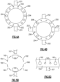
- the bleed exit port 331 has single holes 340 circumferentially adjacent bleed exit port 331, and plural holes 344 circumferentially spaced from bleed exit port 331. This increases the flow area at locations spaced circumferentially from the exit port 331.
- Figure 3D shows an embodiment wherein the bleed exit ports 352 and 354 are relatively close circumferentially, and bleed exit port 356 is further spaced circumferentially. That is, there are unequal distances between the three exit ports 352, 354, 356. Thus, there are relatively large holes 358 in the greater distance between the exit ports 352/354 and exit port 356. The area of the holes 360 and 362 get smaller as one moves toward the exit ports. Conversely, between the closer spaced exit ports 352 and 354 the holes 364 and 370 are not as large as hole 358
- FIG 4A shows an alternative to the baffle plate illustrated Figure 3B , baffle plate 200.
- baffle plate 200 there are two bleed exit ports 231 which are circumferentially spaced by 180 degrees.
- the holes through the baffle plate 200 increase in cross-sectional area from a location 202 adjacent the bleed exit ports 231, towards locations 204 spaced circumferentially away from (e.g., distal to) the bleed exit ports 231.
- Figure 4B shows another embodiment system 250 wherein there are four bleed exit ports 252 circumferentially spaced.
- the system 250 is shown with a baffle plate 254 having smaller holes 256 circumferentially closer to the bleed exit ports 252 and larger holes 258 spaced circumferentially from the bleed exit ports 252. While only two such ports are illustrated it should be understood that a much larger number would likely be utilized.
- holes are shown as circular, holes having other cross-sections would come within the scope of this disclosure.
- the holes would still appropriately vary in cross-sectional area distal to the bleed exit ports.
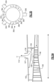
- Figure 5A shows a low pressure bleed system wherein an outer compressor housing 149 surrounds the high pressure compressor 106.
- a bleed inlet passage 109 extends into a chamber 152 radially outwardly of the housing 149.
- the air then encounters a baffle 154 having holes 156 before moving into the bleed.
- the baffle 154 has holes 160 circumferentially associated with the location of the bleed exit port 107 and increasing in cross-sectional area between holes 162 and 166.
- Figure 5C shows the cross-sectional areas of holes 160 and 162 increasing in a circumferential direction moving away from bleed exit port 107. Only a small portion of the baffle plate 154 is illustrated here and in practice there would be more than two sized holes.
- the plate at the lower pressure location extends circumferentially and is cylindrical with the holes extending radially outwardly through the cylindrical section to a bleed outlet line, such as bleed lines 116, 118, or the like.
- baffle plate 230 is shown generally in the location of the Figure 3A baffle plate.
- the baffle plate 232 extends to have radial holes 234 through which the air will move to reach the bleed exit port 231. It should be understood that the size of these holes will vary as shown with regard to the Figure 5A / 5C embodiment.
- any of the above embodiments can be utilized with plural bleed taps, plural outlets, radially or axially extending holes.
- the baffle plate may be formed as shown in Figure 5A to extend with an angle such that the hole has both an axial and a radial component.
- the variation can be achieved by changing hole size or the number of holes, or both.
- a gas turbine engine under this disclosure could be said to include a compressor section having a downstream most location and more upstream locations.
- a compressor housing surrounds the compressor rotors.
- a combustor is downstream of the compressor and a turbine section is downstream of the combustor.
- At least one bleed inlet passage bleeds air compressed air from the compressor section, and delivers the air for use on an associated aircraft.
- a baffle plate is situated intermediate the at least one bleed inlet passage and a bleed exit port from the gas turbine engine.
- the baffle plate has a plurality of holes for allowing the air to flow from the bleed inlet passage to the bleed exit port, with an area of the holes increasing from a location adjacent the at least one bleed inlet passage and in a circumferential direction away from the at least one bleed inlet passage.
Landscapes
- Engineering & Computer Science (AREA)
- Mechanical Engineering (AREA)
- General Engineering & Computer Science (AREA)
- Chemical & Material Sciences (AREA)
- Combustion & Propulsion (AREA)
- Structures Of Non-Positive Displacement Pumps (AREA)
Abstract
A gas turbine engine (20) includes a compressor section (106) having a downstream most location (108) and more upstream locations. A compressor housing (149) surrounds the compressor rotors. A combustor (110) is downstream of the compressor and a turbine section (112) is downstream of the combustor (110). At least one bleed inlet passage bleeds air compressed from the compressor section (106), and delivers the air for use (122) on an associated aircraft (99). A baffle plate (132) is intermediate the at least one bleed inlet passage and a bleed exit port (131) from the gas turbine engine (20). The baffle plate (132) has a plurality of holes (140) for allowing the air to flow from the bleed inlet passage to the bleed exit port (131), with an area of the holes (140) increasing from a location adjacent the at least one bleed inlet passage and in a circumferential direction away from the at least one bleed inlet passage. An aircraft air supply system and an aircraft are also disclosed.
Description
- This application relates to baffles to improve the bleeding of compressor air from a gas turbine engine.
- Gas turbine engines are known, and typically include a fan delivering air into a bypass duct as propulsion air. Air is also delivered into a compressor. The compressed air is delivered into a combustor where it is mixed with fuel and ignited. Products of this combustion pass downstream over turbine rotors driving them to rotate. The turbine rotors in turn drive the compressor and fan rotors.
- It is known to bleed compressed air from the compressor section for various uses on an associated aircraft. As one example, a bleed system is utilized that bleeds air from a lower pressure location in the compressor section and also from a higher pressure location. Controls and valving select which of these air supplies is sent to an aircraft cabin air conditioning system.
- At low power operation of the engine the air is bled from the higher-pressure section, and at higher power operation the air is bled from a lower pressure section of the compressor. Examples of the higher power operation include takeoff whereas as the lower power operation include at ground idle. This selective use is done to avoid using air that is over-pressurized and at excessively high temperature for the end use.
- Typically, a plurality of bleed ports are packaged into each of these locations (e.g., higher-pressure section, lower pressure section). Further, there are challenges in maintaining adequate engine stability margins while operating these bleed systems.
- In a featured embodiment, a gas turbine engine includes a compressor section having a downstream most location and more upstream locations. A compressor housing surrounds the compressor rotors. A combustor is downstream of the compressor and a turbine section is downstream of the combustor. At least one bleed inlet passage bleeds air compressed from the compressor section, and delivers the air for use on an associated aircraft. A baffle plate is intermediate the at least one bleed inlet passage and a bleed exit port from the gas turbine engine. The baffle plate has a plurality of holes for allowing the air to flow from the bleed inlet passage to the bleed exit port, with an area of the holes increasing from a location adjacent the at least one bleed inlet passage and in a circumferential direction away from the at least one bleed inlet passage.
- In another embodiment according to the previous embodiment, there are at least two bleed inlet passages, associated baffle plates and bleed exit ports with one of the bleed inlet passages associated with a higher pressure location and one of the bleed inlet passages associated with a lower pressure location in the compressor section.
- In another embodiment according to any of the previous embodiments, the bleed inlet passage associated with the lower pressure location extends through a housing of the compressor section.
- In another embodiment according to any of the previous embodiments, the higher pressure location is downstream of the downstream most location in the compressor section, with the bleed inlet passage being a downstream end of a compressor diffuser.
- In another embodiment according to any of the previous embodiments, the baffle plate associated with the higher pressure location is attached to the compressor diffuser.
- In another embodiment according to any of the previous embodiments, the baffle plate at the lower pressure location extends circumferentially and is cylindrical with the holes extending with at least a component in a radially outward direction through the cylindrical section to the bleed exit port.
- In another embodiment according to any of the previous embodiments, the baffle plate is at the higher pressure location, with the holes extending with at least a component in an axial direction through the baffle plate to the bleed outlet line.
- In another embodiment according to any of the previous embodiments, the baffle plate at the higher pressure location is generally circular, with the holes extending with at least a component in an axial direction through the baffle plate to the bleed exit port.
- In another embodiment according to any of the previous embodiments, each of the bleed exit ports are to be connected to a use through a valve having an electric control to select between the two bleed exit ports lines to connect to the use.
- In another embodiment according to any of the previous embodiments, the use is a cabin air supply system for the associated aircraft.
- In another embodiment according to any of the previous embodiments, the increase in the area of the holes is achieved by increasing the size of the holes.
- In another embodiment according to any of the previous embodiments, the increase in the area of the holes is achieved by increasing the quantity of the holes.
- In another featured embodiment, an aircraft air supply system includes a gas turbine engine including a compressor section having a downstream most location and more upstream locations. A compressor housing surrounds compressor rotors, a combustor downstream of the compressor and a turbine section downstream of the combustor. At least one bleed inlet passage bleeds air compressed in the compressor section, and delivers the air for use on an associated aircraft. A baffle plate is intermediate the at least one bleed inlet passage and a bleed exit port from the gas turbine engine. The baffle plate has a plurality of holes for allowing the air to flow from the bleed inlet passage to the bleed exit port, with an area of the holes increasing from a location adjacent the at least one bleed exit port and in a circumferential direction away from the at least one bleed exit port. The bleed exit port is to be connected to the use.
- In another embodiment according to any of the previous embodiments, there are at least two inlet passages, associated baffle plates and bleed exit ports with one of the bleed inlet passages associated with a higher pressure location and one of the bleed inlet passages associated with a lower pressure location in the compressor section. Each of the bleed exit port is to be connected to the use through a valve having an electric control to select between the two bleed exit ports to connect to the use. The use is a cabin air supply system for the associated aircraft.
- In another embodiment according to any of the previous embodiments, the bleed inlet passage associated with the lower pressure location extends through a housing of the compressor section.
- In another embodiment according to any of the previous embodiments, the higher pressure location is downstream of the downstream most location in the compressor section, with the bleed inlet passage being a downstream end of a compressor diffuser.
- In another embodiment according to any of the previous embodiments, the baffle plate at the lower pressure location extends circumferentially and is cylindrical with the holes extending with at least a component in a radially outward direction through the cylindrical section to the bleed outlet line.
- In another embodiment according to any of the previous embodiments, the baffle plate is at the higher pressure location, with the holes extending with at least a component in an axial direction through the baffle plate to the bleed outlet line.
- In another embodiment according to any of the previous embodiments, the baffle plate is generally thin and with the holes extending with at least a component in an axial direction through the baffle plate to the bleed exit port.
- In another featured embodiment, an aircraft includes an aircraft body including a gas turbine engine including a compressor section having a downstream most location and more upstream locations. A compressor housing surrounds compressor rotors, a combustor downstream of the compressor and a turbine section downstream of the combustor. At least one bleed inlet passage bleeds air compressed in the compressor section, and delivers the air for use on an associated aircraft. A baffle plate is intermediate the at least one bleed inlet passage and a bleed exit port from the gas turbine engine. The baffle plate has a plurality of holes for allowing the air to flow from the bleed inlet passage to the bleed exit port connection, with an area of the holes increasing from a location adjacent the at least one bleed exit port and in a circumferential direction away from the at least one bleed exit port. The bleed exit port is to be connected to the use. There are at least two bleed inlet passages, associated baffle plates and bleed exit ports with one of the bleed inlet passages associated with a higher pressure location and one of the bleed inlet passages associated with a lower pressure location in the compressor section. Each of the bleed exit port is to be connected to the use through a valve having an electric control to select between the two bleed exit port to connect to the use. The use is a cabin air supply system for the associated aircraft.
- The present disclosure may include any one or more of the individual features disclosed above and/or below alone or in any combination thereof.
- These and other features of the present invention can be best understood from the following specification and drawings, the following of which is a brief description.
-
-
Figure 1 schematically shows a gas turbine engine. -
Figure 2 schematically shows a bleed air system in an aircraft. -
Figure 3A shows a first bleed location. -
Figure 3B shows a first embodiment of a diffuser baffle. -
Figure 3C shows another embodiment. -
Figure 3D shows another embodiment. -
Figure 4A shows an alternative to theFigure 3B baffle. -
Figure 4B shows an alternative to theFigure 3B baffle. -
Figure 5A shows another bleed location. -
Figure 5B is a circumferential view of the baffle in theFigure 5A embodiment. -
Figure 5C is another view of theFigure 5B baffle. -
Figure 6 shows another alternative to theFigure 3B baffle. -
Figure 1 schematically illustrates agas turbine engine 20. Thegas turbine engine 20 is disclosed herein as a two-spool turbofan that generally incorporates afan section 22, acompressor section 24, a combustor section 26 and aturbine section 28. Thefan section 22 may include a single-stage fan 42 having a plurality offan blades 43. Thefan blades 43 may have a fixed stagger angle or may have a variable pitch to direct incoming airflow from an engine inlet. Thefan 42 drives air along a bypass flow path B in abypass duct 13 defined within ahousing 15 such as a fan case or nacelle, and also drives air along a core flow path C for compression and communication into the combustor section 26 then expansion through theturbine section 28. Asplitter 29 aft of thefan 42 divides the air between the bypass flow path B and the core flow path C. Thehousing 15 may surround thefan 42 to establish an outer diameter of thebypass duct 13. Thesplitter 29 may establish an inner diameter of thebypass duct 13. Although depicted as a two-spool turbofan gas turbine engine in the disclosed nonlimiting embodiment, it should be understood that the concepts described herein are not limited to use with two-spool turbofans as the teachings may be applied to other types of turbine engines including three-spool architectures. Theengine 20 may incorporate a variable area nozzle for varying an exit area of the bypass flow path B and/or a thrust reverser for generating reverse thrust. - The
exemplary engine 20 generally includes alow speed spool 30 and ahigh speed spool 32 mounted for rotation about an engine central longitudinal axis A relative to an enginestatic structure 36 viaseveral bearing systems 38. It should be understood that various bearingsystems 38 at various locations may alternatively or additionally be provided, and the location of bearingsystems 38 may be varied as appropriate to the application. - The
low speed spool 30 generally includes aninner shaft 40 that interconnects, a first (or low)pressure compressor 44 and a first (or low)pressure turbine 46. Theinner shaft 40 is connected to thefan 42 through a speed change mechanism, which in the exemplarygas turbine engine 20 is illustrated as a gearedarchitecture 48 to drive thefan 42 at a lower speed than thelow speed spool 30. Theinner shaft 40 may interconnect thelow pressure compressor 44 andlow pressure turbine 46 such that thelow pressure compressor 44 andlow pressure turbine 46 are rotatable at a common speed and in a common direction. In other embodiments, thelow pressure turbine 46 drives both thefan 42 andlow pressure compressor 44 through the gearedarchitecture 48 such that thefan 42 andlow pressure compressor 44 are rotatable at a common speed. Although this application discloses gearedarchitecture 48, its teaching may benefit direct drive engines having no geared architecture. Thehigh speed spool 32 includes anouter shaft 50 that interconnects a second (or high)pressure compressor 52 and a second (or high)pressure turbine 54. Acombustor 56 is arranged in theexemplary gas turbine 20 between thehigh pressure compressor 52 and thehigh pressure turbine 54. Amid-turbine frame 57 of the enginestatic structure 36 may be arranged generally between thehigh pressure turbine 54 and thelow pressure turbine 46. Themid-turbine frame 57 furthersupports bearing systems 38 in theturbine section 28. Theinner shaft 40 and theouter shaft 50 are concentric and rotate via bearingsystems 38 about the engine central longitudinal axis A which is collinear with their longitudinal axes. The shafts may co-rotate or counter-rotate. - Airflow in the core flow path C is compressed by the
low pressure compressor 44 then thehigh pressure compressor 52, mixed and burned with fuel in thecombustor 56, then expanded through thehigh pressure turbine 54 andlow pressure turbine 46. Themid-turbine frame 57 includesairfoils 59 which are in the core flow path C. Theturbines low speed spool 30 andhigh speed spool 32 in response to the expansion. It will be appreciated that each of the positions of thefan section 22,compressor section 24, combustor section 26,turbine section 28, and fandrive gear system 48 may be varied. For example,gear system 48 may be located aft of the low pressure compressor, or aft of the combustor section 26 or even aft ofturbine section 28, andfan 42 may be positioned forward or aft of the location ofgear system 48. - The
fan 42 may have at least 10fan blades 43 but no more than 20 or 24fan blades 43. In examples, thefan 42 may have between 12 and 18fan blades 43, such as 14fan blades 43. An exemplary fan size measurement is a maximum radius between the tips of thefan blades 43 and the engine central longitudinal axis A. The maximum radius of thefan blades 43 can be at least 40 inches, or more narrowly no more than 75 inches. For example, the maximum radius of thefan blades 43 can be between 45 inches and 60 inches, such as between 50 inches and 55 inches. Another exemplary fan size measurement is a hub radius, which is defined as distance between a hub of thefan 42 at a location of the leading edges of thefan blades 43 and the engine central longitudinal axis A. Thefan blades 43 may establish a fan hub-to-tip ratio, which is defined as a ratio of the hub radius divided by the maximum radius of thefan 42. The fan hub-to-tip ratio can be less than or equal to 0.35, or more narrowly greater than or equal to 0.20, such as between 0.25 and 0.30. The combination of fan blade counts and fan hub-to-tip ratios disclosed herein can provide theengine 20 with a relatively compact fan arrangement. - The
low pressure compressor 44,high pressure compressor 52,high pressure turbine 54 andlow pressure turbine 46 each include one or more stages having a row of rotatable airfoils. Each stage may include a row of vanes adjacent the rotatable airfoils. The rotatable airfoils are schematically indicated at 47, and the vanes are schematically indicated at 49. - The
low pressure compressor 44 andlow pressure turbine 46 can include an equal number of stages. For example, theengine 20 can include a three-stagelow pressure compressor 44, an eight-stagehigh pressure compressor 52, a two-stagehigh pressure turbine 54, and a three-stagelow pressure turbine 46 to provide a total of sixteen stages. In other examples, thelow pressure compressor 44 includes a different (e.g., greater) number of stages than thelow pressure turbine 46. For example, theengine 20 can include a five-stagelow pressure compressor 44, a nine-stagehigh pressure compressor 52, a two-stagehigh pressure turbine 54, and a four-stagelow pressure turbine 46 to provide a total of twenty stages. In other embodiments, theengine 20 includes a four-stagelow pressure compressor 44, a nine-stagehigh pressure compressor 52, a two-stagehigh pressure turbine 54, and a three-stagelow pressure turbine 46 to provide a total of eighteen stages. It should be understood that theengine 20 can incorporate other compressor and turbine stage counts, including any combination of stages disclosed herein. - The
engine 20 may be a high-bypass geared aircraft engine. The bypass ratio can be greater than or equal to 10.0 and less than or equal to about 18.0, or more narrowly can be less than or equal to 16.0. The gearedarchitecture 48 may be an epicyclic gear train, such as a planetary gear system or a star gear system. The epicyclic gear train may include a sun gear, a ring gear, a plurality of intermediate gears meshing with the sun gear and ring gear, and a carrier that supports the intermediate gears. The sun gear may provide an input to the gear train. The ring gear (e.g., star gear system) or carrier (e.g., planetary gear system) may provide an output of the gear train to drive thefan 42. A gear reduction ratio may be greater than or equal to 2.3, or more narrowly greater than or equal to 3.0, and in some embodiments the gear reduction ratio is greater than or equal to 3.4. The gear reduction ratio may be less than or equal to 4.0. The fan diameter is significantly larger than that of thelow pressure compressor 44. Thelow pressure turbine 46 can have a pressure ratio that is greater than or equal to 8.0 and in some embodiments is greater than or equal to 10.0. The low pressure turbine pressure ratio can be less than or equal to 13.0, or more narrowly less than or equal to 12.0.Low pressure turbine 46 pressure ratio is pressure measured prior to an inlet oflow pressure turbine 46 as related to the pressure at the outlet of thelow pressure turbine 46 prior to an exhaust nozzle. It should be understood, however, that the above parameters are only exemplary of one embodiment of a geared architecture engine and that the present invention is applicable to other gas turbine engines including direct drive turbofans. All of these parameters are measured at the cruise condition described below. - A significant amount of thrust is provided by the bypass flow B due to the high bypass ratio. The
fan section 22 of theengine 20 is designed for a particular flight condition -- typically cruise at about 0.8 Mach and about 35,000 feet (10,668 meters). The flight condition of 0.8 Mach and 35,000 ft (10,668 meters), with the engine at its best fuel consumption - also known as "bucket cruise Thrust Specific Fuel Consumption ('TSFC')" - is the industry standard parameter of lbm of fuel being burned divided by lbf of thrust the engine produces at that minimum point. The engine parameters described above, and those in the next paragraph are measured at this condition unless otherwise specified. - "Fan pressure ratio" is the pressure ratio across the
fan blade 43 alone, without a Fan Exit Guide Vane ("FEGV") system. A distance is established in a radial direction between the inner and outer diameters of thebypass duct 13 at an axial position corresponding to a leading edge of thesplitter 29 relative to the engine central longitudinal axis A. The fan pressure ratio is a spanwise average of the pressure ratios measured across thefan blade 43 alone over radial positions corresponding to the distance. The fan pressure ratio can be less than or equal to 1.45, or more narrowly greater than or equal to 1.25, such as between 1.30 and 1.40. "Corrected fan tip speed" is the actual fan tip speed in ft/sec divided by an industry standard temperature correction of [(Tram °R) / (518.7 °R)]0.5. The corrected fan tip speed can be less than or equal to 1150.0 ft / second (350.5 meters/second), and can be greater than or equal to 1000.0 ft / second (304.8 meters/second). - The
fan 42,low pressure compressor 44 andhigh pressure compressor 52 can provide different amounts of compression of the incoming airflow that is delivered downstream to theturbine section 28 and cooperate to establish an overall pressure ratio (OPR). The OPR is a product of the fan pressure ratio across a root (i.e., 0% span) of thefan blade 43 alone, a pressure ratio across thelow pressure compressor 44 and a pressure ratio across thehigh pressure compressor 52. The pressure ratio of thelow pressure compressor 44 is measured as the pressure at the exit of thelow pressure compressor 44 divided by the pressure at the inlet of thelow pressure compressor 44. In examples, a sum of the pressure ratio of thelow pressure compressor 44 and the fan pressure ratio is between 3.0 and 6.0, or more narrowly is between 4.0 and 5.5. The pressure ratio of the highpressure compressor ratio 52 is measured as the pressure at the exit of thehigh pressure compressor 52 divided by the pressure at the inlet of thehigh pressure compressor 52. In examples, the pressure ratio of thehigh pressure compressor 52 is between 9.0 and 12.0, or more narrowly is between 10.0 and 11.5. The OPR can be equal to or greater than 45.0, and can be less than or equal to 70.0, such as between 50.0 and 60.0. The overall and compressor pressure ratios disclosed herein are measured at the cruise condition described above, and can be utilized in two-spool architectures such as theengine 20 as well as three-spool engine architectures. - The
engine 20 establishes a turbine entry temperature (TET). The TET is defined as a maximum temperature of combustion products communicated to an inlet of theturbine section 28 at a maximum takeoff (MTO) condition. The inlet is established at the leading edges of the axially forwardmost row of airfoils of theturbine section 28, and MTO is measured at maximum thrust of theengine 20 at static sea-level and 86 degrees Fahrenheit (°F). The TET may be greater than or equal to 2700.0 °F, or more narrowly less than or equal to 3500.0 °F, such as between 2750.0 °F and 3350.0 °F. The relatively high TET can be utilized in combination with the other techniques disclosed herein to provide a compact turbine arrangement. - The
engine 20 establishes an exhaust gas temperature (EGT). The EGT is defined as a maximum temperature of combustion products in the core flow path C communicated to at the trailing edges of the axially aftmost row of airfoils of theturbine section 28 at the MTO condition. The EGT may be less than or equal to 1000.0 °F, or more narrowly greater than or equal to 800.0 °F, such as between 900.0 °F and 975.0 °F. The relatively low EGT can be utilized in combination with the other techniques disclosed herein to reduce fuel consumption. -
Figure 2 shows anengine bleed system 100 schematically. Afan 102 delivers air into alow pressure compressor 104 and abypass duct 103. The air passes into ahigh pressure compressor 106. - The
high pressure compressor 106 has a mostdownstream location 108. - From the
compressor section 106 the air moves into acombustor 110 where it is ignited. The air then passes over aturbine section 112 and outwardly of anexhaust nozzle 114. - A bleed system includes a
first bleed line 116 from an upstream tap locationbleed exit port 107 in thehigh pressure compressor 106 that is upstream of the mostdownstream location 108. Asecond bleed line 118 is from a higher pressure tap locationbleed exit port 131. In the example the higher pressure location is the mostdownstream location 108, although other locations may be utilized. As illustrated inFigure 3A thebleed exit port 131 is from the diffuser downstream of the compressor. Further, while the location of thebleed exit port 107 forfirst bleed line 116 is in the high pressure compressor, it may also be somewhere within thelow pressure compressor 104. - A
valve 121 is controlled by acontrol 120 to selectively send air between the twobleed lines use 122. In one embodiment theuse 122 could be a cabin air conditioning system for an associatedaircraft 99, shown schematically. - While
bleed lines -
Figure 3A shows detail of thebleed exit port 131. Air from the mostdownstream location 108 moves into acompressor diffuser 130. That air exits the diffuser and then moves toward thecombustor 110. Some of this air passes through abaffle plate 132 to bleedexit port 131 and intoline 118. In this sense, theentire compressor diffuser 130 act as a bleed inlet passage. The air moves through aplenum 133 between thebaffle plate 132 and thebleed exit port 131. In at least one example, thebaffle plate 132 may be coupled or attached to thecompressor diffuser 130, such as via one or more couplings. -
Figure 3B shows thebaffle plate 132. In the illustrative example, thebaffle plate 132 includes apertures or holes 140 that extend through thebaffle plate 132. Moving circumferentially away from the location of thebleed exit port 131 the apertures 144/146/148/150 get progressively larger. This type of pattern encourages flow circumferentially all around the circumference of thebaffle 132 such that the air passing downstream of thebaffle plate 132 tends to be dispersed and evenly distributed. An ideal state can be reached when the sum of baffle loss and circumferential manifold loss equals a constant. Circumferentially similar baffle flow results in the pressure of theflow entering combustor 110 to also be close to uniform circumferentially, a condition beneficial for good combustion and more uniform downstream flow. Withoutbaffle plate 132 the air reachingbleed exit port 131 would be more local to the outlet and this would reduce the efficient provision of air tocombustor 110. - The baffle plate at the higher pressure location is generally circular, with the holes extending in an axial direction through the baffle plate to the
bleed exit port 131 andline 118. - Note non-uniformly spaced output ports can be similarly optimized by again making the sum of baffle loss and circumferential manifold baffle loss equal around the circumference. In such a baffle the cross-sectional area of the holes at each successive location would increase moving away from the outlets. Thus, as shown in
Figure 3C , in anembodiment 330 thebleed exit port 331 hassingle holes 340 circumferentially adjacentbleed exit port 331, andplural holes 344 circumferentially spaced frombleed exit port 331. This increases the flow area at locations spaced circumferentially from theexit port 331. As with all of these embodiments, it should be understood that for simplicity of illustration only a few holes are illustrated, but in practice, there may be many more holes. It should also be noted that larger holes with the same total area can be used instead of multiple holes at any particular location. -
Figure 3D shows an embodiment wherein thebleed exit ports exit port 356 is further spaced circumferentially. That is, there are unequal distances between the threeexit ports large holes 358 in the greater distance between theexit ports 352/354 andexit port 356. The area of theholes exit ports holes hole 358 -
Figure 4A shows an alternative to the baffle plate illustratedFigure 3B ,baffle plate 200. Inembodiment 200, there are twobleed exit ports 231 which are circumferentially spaced by 180 degrees. The holes through thebaffle plate 200 increase in cross-sectional area from alocation 202 adjacent thebleed exit ports 231, towardslocations 204 spaced circumferentially away from (e.g., distal to) thebleed exit ports 231. -
Figure 4B shows anotherembodiment system 250 wherein there are fourbleed exit ports 252 circumferentially spaced. Thesystem 250 is shown with abaffle plate 254 havingsmaller holes 256 circumferentially closer to thebleed exit ports 252 andlarger holes 258 spaced circumferentially from thebleed exit ports 252. While only two such ports are illustrated it should be understood that a much larger number would likely be utilized. - While the holes are shown as circular, holes having other cross-sections would come within the scope of this disclosure. The holes would still appropriately vary in cross-sectional area distal to the bleed exit ports.
-
Figure 5A shows a low pressure bleed system wherein anouter compressor housing 149 surrounds thehigh pressure compressor 106. Ableed inlet passage 109 extends into achamber 152 radially outwardly of thehousing 149. In practice there are pluralbleed inlet passages 109. The air then encounters abaffle 154 havingholes 156 before moving into the bleed. - As shown in
Figure 5B thebaffle 154 hasholes 160 circumferentially associated with the location of thebleed exit port 107 and increasing in cross-sectional area betweenholes Figure 5B there is a secondbleed exit port 151 such that theholes baffle plate 154. However, similar to theFigure 3B embodiment there may be a single bleed exit port with theFigure 5A embodiment. -
Figure 5C shows the cross-sectional areas ofholes bleed exit port 107. Only a small portion of thebaffle plate 154 is illustrated here and in practice there would be more than two sized holes. - The plate at the lower pressure location extends circumferentially and is cylindrical with the holes extending radially outwardly through the cylindrical section to a bleed outlet line, such as
bleed lines - Another
embodiment baffle plate 230 is shown generally in the location of theFigure 3A baffle plate. Here thebaffle plate 232 extends to haveradial holes 234 through which the air will move to reach thebleed exit port 231. It should be understood that the size of these holes will vary as shown with regard to theFigure 5A /5C embodiment. - Any of the above embodiments can be utilized with plural bleed taps, plural outlets, radially or axially extending holes. In fact, the baffle plate may be formed as shown in
Figure 5A to extend with an angle such that the hole has both an axial and a radial component. Also, the variation can be achieved by changing hole size or the number of holes, or both. - A gas turbine engine under this disclosure could be said to include a compressor section having a downstream most location and more upstream locations. A compressor housing surrounds the compressor rotors. A combustor is downstream of the compressor and a turbine section is downstream of the combustor. At least one bleed inlet passage bleeds air compressed air from the compressor section, and delivers the air for use on an associated aircraft. A baffle plate is situated intermediate the at least one bleed inlet passage and a bleed exit port from the gas turbine engine. The baffle plate has a plurality of holes for allowing the air to flow from the bleed inlet passage to the bleed exit port, with an area of the holes increasing from a location adjacent the at least one bleed inlet passage and in a circumferential direction away from the at least one bleed inlet passage.
- Although embodiments have been disclosed, a worker of ordinary skill in this art would recognize that modifications would come within the scope of this disclosure. For that reason, the following claims should be studied to determine the true scope and content of this disclosure.
Claims (15)
- A gas turbine engine (20) comprising:a compressor section (106) having a downstream most location (108) and more upstream locations and a compressor housing (149) surrounding compressor rotors, a combustor (110) downstream of said compressor and a turbine section (112) downstream of said combustor (110);at least one bleed inlet passage for bleeding air compressed from the compressor section (106), and delivering the air for use (122) on an associated aircraft (99); anda baffle plate (132) intermediate the at least one bleed inlet passage and a bleed exit port (131) from the gas turbine engine (20), the baffle plate (132) having a plurality of holes (140) for allowing the air to flow from the bleed inlet passage to the bleed exit port (131), with an area of the holes (140) increasing from a location adjacent the at least one bleed inlet passage and in a circumferential direction away from the at least one bleed exit port (131).
- The gas turbine engine (20) as set forth in claim 1, wherein there are at least two bleed inlet passages, associated baffle plates (132) and bleed exit ports (107, 131) with one of said bleed inlet passages associated with a higher pressure location and one of the bleed inlet passages associated with a lower pressure location in the compressor section (106).
- The gas turbine engine (20) as set forth in claim 2, wherein said bleed inlet passage associated with said lower pressure location extends through a housing (149) of the compressor section (106).
- The gas turbine engine (20) as set forth in claim 2 or 3, wherein the higher pressure location is downstream of the downstream most location (108) in the compressor section (106), with the bleed inlet passage being a downstream end of a compressor diffuser (130).
- The gas turbine engine (20) as set forth in any of claims 2 to 4, wherein the baffle plate (132) associated with the higher pressure location is attached to a compressor diffuser (130).
- The gas turbine engine (20) as set forth in any of claims 2 to 5, wherein said baffle plate (230) at the lower pressure location extends circumferentially and is cylindrical with said holes (234) extending with at least a component in a radially outward direction through said cylindrical section to the bleed exit port (231).
- The gas turbine engine (20) as set forth in any of claims 2 to 5, wherein the baffle plate (132) at the higher pressure location is generally circular, with said holes (140) extending with at least a component in an axial direction through said baffle plate (132) to the bleed exit port (131).
- The gas turbine engine (20) as set forth in any of claims 2 to 7, wherein holes (140) of the baffle plate (132) at the higher pressure location extend with at least a component in an axial direction through said baffle plate (132) to a bleed outlet line (118).
- The gas turbine engine (20) as set forth in any of claims 2 to 8, each of said bleed exit ports (107, 131) configured to be connected to a use (122) through a valve (121) having an electric control (120) to select between the two bleed exit ports (107, 131) to connect to the use (122).
- The gas turbine engine (20) as set forth in claim 9, wherein the use (122) is a cabin air supply system for the associated aircraft (99).
- The gas turbine engine (20) as set forth in any preceding claim, wherein the increase in the area of the holes (140) is achieved by increasing the size of the holes (140).
- The gas turbine engine (20) as set forth in any preceding claim, wherein the increase in the area of the holes (340) is achieved by increasing the quantity of the holes (340).
- An aircraft air supply system comprising:
the gas turbine engine (20) of any preceding claim, wherein said bleed exit port (107, 131) is configured to be connected to the use (122) on the associated aircraft (99). - The system as set forth in claim 13, wherein the baffle plate (132) is generally thin and said holes (140) extend with at least a component in an axial direction through said baffle plate (132) to the bleed exit port (107, 131).
- An aircraft comprising:an aircraft body including a gas turbine engine (20) including a compressor section (106) having a downstream most location (108) and more upstream locations and a compressor housing (149) surrounding compressor rotors, a combustor (110) downstream of said compressor and a turbine section (112) downstream of said combustor (110);at least one bleed inlet passage for bleeding air compressed in the compressor section (106), and delivering the air for use (122) on an associated aircraft (99);a baffle plate (132) intermediate the at least one bleed inlet passage and a bleed exit port (107, 131) from the gas turbine engine (20), the baffle plate (132) having a plurality of holes (140) for allowing the air to flow from the bleed inlet passage to the bleed exit port (107, 131) connection, with an area of the holes (140) increasing from a location adjacent the at least one bleed exit port (107, 131) and in a circumferential direction away from the at least one bleed exit port (107, 131);said bleed exit port (107, 131) to be connected to the use (122); andwherein there are at least two bleed inlet passages, associated baffle plates (132) and bleed exit ports (107, 131) with one of said bleed inlet passages associated with a higher pressure location and one of the bleed inlet passages associated with a lower pressure location in the compressor section (106), each of said bleed exit port (107, 131) to be connected to the use (122) through a valve (121) having an electric control (120) to select between the two bleed exit port (107, 131) to connect to the use (122), and the use (122) is a cabin air supply system for the associated aircraft (99).
Applications Claiming Priority (1)
| Application Number | Priority Date | Filing Date | Title |
|---|---|---|---|
| US18/171,092 US12595762B2 (en) | 2023-02-17 | 2023-02-17 | Gas turbine engine with bleed diffuser baffles |
Publications (1)
| Publication Number | Publication Date |
|---|---|
| EP4417795A1 true EP4417795A1 (en) | 2024-08-21 |
Family
ID=89983060
Family Applications (1)
| Application Number | Title | Priority Date | Filing Date |
|---|---|---|---|
| EP24158183.4A Pending EP4417795A1 (en) | 2023-02-17 | 2024-02-16 | Gas turbine engine with bleed diffuser baffles |
Country Status (2)
| Country | Link |
|---|---|
| US (1) | US12595762B2 (en) |
| EP (1) | EP4417795A1 (en) |
Citations (5)
| Publication number | Priority date | Publication date | Assignee | Title |
|---|---|---|---|---|
| US20090000307A1 (en) * | 2007-06-27 | 2009-01-01 | Toyota Jidosha Kabushiki Kaisha | Air-bleed gas turbine |
| EP2492199A2 (en) * | 2011-02-28 | 2012-08-29 | General Electric Company | Environmental control system supply precooler bypass |
| WO2014098936A1 (en) * | 2012-12-18 | 2014-06-26 | United Technologies Corporation | Gas turbine engine inner case including non-symmetrical bleed slots |
| DE102019110834A1 (en) * | 2019-04-26 | 2020-10-29 | Rolls-Royce Deutschland Ltd & Co Kg | Bleed air extraction device for a gas turbine engine |
| CN113062800A (en) * | 2021-04-19 | 2021-07-02 | 中国航发湖南动力机械研究所 | Environment-friendly bleed air structure of aircraft engine and aircraft |
Family Cites Families (9)
| Publication number | Priority date | Publication date | Assignee | Title |
|---|---|---|---|---|
| US5160241A (en) | 1991-09-09 | 1992-11-03 | General Electric Company | Multi-port air channeling assembly |
| US5351478A (en) * | 1992-05-29 | 1994-10-04 | General Electric Company | Compressor casing assembly |
| US5632141A (en) * | 1994-09-09 | 1997-05-27 | United Technologies Corporation | Diffuser with controlled diffused air discharge |
| FR2829193B1 (en) | 2001-08-30 | 2005-04-08 | Snecma Moteurs | AIR COLLECTION SYSTEM OF A COMPRESSOR |
| US7374396B2 (en) | 2005-02-28 | 2008-05-20 | General Electric Company | Bolt-on radial bleed manifold |
| GB201410180D0 (en) * | 2014-06-09 | 2014-07-23 | Rolls Royce Plc | Method and apparatus for controlling a compressor of a gas turbine engine |
| US10513984B2 (en) * | 2015-08-25 | 2019-12-24 | General Electric Company | System for suppressing acoustic noise within a gas turbine combustor |
| FR3048017B1 (en) * | 2016-02-24 | 2019-05-31 | Safran Aircraft Engines | AIRCRAFT TURBOMACHINE COMPRESSOR RECTIFIER, COMPRISING STRIPPED AIR-LIFTING ORIFICES ACCORDING TO THE CIRCUMFERENTIAL DIRECTION |
| US11486262B2 (en) | 2021-03-03 | 2022-11-01 | General Electric Company | Diffuser bleed assembly |
-
2023
- 2023-02-17 US US18/171,092 patent/US12595762B2/en active Active
-
2024
- 2024-02-16 EP EP24158183.4A patent/EP4417795A1/en active Pending
Patent Citations (5)
| Publication number | Priority date | Publication date | Assignee | Title |
|---|---|---|---|---|
| US20090000307A1 (en) * | 2007-06-27 | 2009-01-01 | Toyota Jidosha Kabushiki Kaisha | Air-bleed gas turbine |
| EP2492199A2 (en) * | 2011-02-28 | 2012-08-29 | General Electric Company | Environmental control system supply precooler bypass |
| WO2014098936A1 (en) * | 2012-12-18 | 2014-06-26 | United Technologies Corporation | Gas turbine engine inner case including non-symmetrical bleed slots |
| DE102019110834A1 (en) * | 2019-04-26 | 2020-10-29 | Rolls-Royce Deutschland Ltd & Co Kg | Bleed air extraction device for a gas turbine engine |
| CN113062800A (en) * | 2021-04-19 | 2021-07-02 | 中国航发湖南动力机械研究所 | Environment-friendly bleed air structure of aircraft engine and aircraft |
Also Published As
| Publication number | Publication date |
|---|---|
| US12595762B2 (en) | 2026-04-07 |
| US20240280050A1 (en) | 2024-08-22 |
Similar Documents
| Publication | Publication Date | Title |
|---|---|---|
| US11608796B1 (en) | Radial strut frame connection between fan case and core housing in a gas turbine engine | |
| US11719245B2 (en) | Compressor arrangement for a gas turbine engine | |
| EP3054138B1 (en) | Turbo-compressor with geared turbofan | |
| US10526915B2 (en) | Firewall mount hub | |
| US12123310B2 (en) | Gas turbine engine with idle thrust ratio | |
| EP4417795A1 (en) | Gas turbine engine with bleed diffuser baffles | |
| EP3351767B1 (en) | Intercooled cooling air system with bypass | |
| EP4495402B1 (en) | Bifurcation air scoop for gas turbine engine | |
| US12618363B2 (en) | Bifurcation air scoop for gas turbine engine | |
| US12392280B2 (en) | Gas turbine engine with high low spool power extraction ratio | |
| US12123356B2 (en) | Gas turbine engine with higher low spool torque-to-thrust ratio | |
| US12098681B2 (en) | High and low spool configuration for a gas turbine engine | |
| US11927140B1 (en) | Gas turbine engine with guided bleed air dump | |
| EP4502340A1 (en) | Control of leakage for gas turbine engine compressor blades | |
| EP4123155A1 (en) | High and low spool configuration for a gas turbine engine | |
| US12435640B2 (en) | Gas turbine engine vane outer diameter platform integrated with blade outer air seal | |
| US12187451B1 (en) | Dual speed planetary gear system for convertible engines | |
| EP4390107B1 (en) | Aft mounted pusher fan for gas turbine engine | |
| EP4123148A1 (en) | Gas turbine engine compressor arrangement | |
| EP4311917A1 (en) | Bleed hole flow discourager |
Legal Events
| Date | Code | Title | Description |
|---|---|---|---|
| PUAI | Public reference made under article 153(3) epc to a published international application that has entered the european phase |
Free format text: ORIGINAL CODE: 0009012 |
|
| STAA | Information on the status of an ep patent application or granted ep patent |
Free format text: STATUS: THE APPLICATION HAS BEEN PUBLISHED |
|
| AK | Designated contracting states |
Kind code of ref document: A1 Designated state(s): AL AT BE BG CH CY CZ DE DK EE ES FI FR GB GR HR HU IE IS IT LI LT LU LV MC ME MK MT NL NO PL PT RO RS SE SI SK SM TR |
|
| STAA | Information on the status of an ep patent application or granted ep patent |
Free format text: STATUS: REQUEST FOR EXAMINATION WAS MADE |
|
| 17P | Request for examination filed |
Effective date: 20250221 |