EP4417727A1 - Galvanized steel sheet and member, and method for producing same - Google Patents
Galvanized steel sheet and member, and method for producing same Download PDFInfo
- Publication number
- EP4417727A1 EP4417727A1 EP22924003.1A EP22924003A EP4417727A1 EP 4417727 A1 EP4417727 A1 EP 4417727A1 EP 22924003 A EP22924003 A EP 22924003A EP 4417727 A1 EP4417727 A1 EP 4417727A1
- Authority
- EP
- European Patent Office
- Prior art keywords
- less
- steel sheet
- area fraction
- galvanized steel
- content
- Prior art date
- Legal status (The legal status is an assumption and is not a legal conclusion. Google has not performed a legal analysis and makes no representation as to the accuracy of the status listed.)
- Pending
Links
Images

Classifications
-
- C—CHEMISTRY; METALLURGY
- C21—METALLURGY OF IRON
- C21D—MODIFYING THE PHYSICAL STRUCTURE OF FERROUS METALS; GENERAL DEVICES FOR HEAT TREATMENT OF FERROUS OR NON-FERROUS METALS OR ALLOYS; MAKING METAL MALLEABLE, e.g. BY DECARBURISATION OR TEMPERING
- C21D9/00—Heat treatment, e.g. annealing, hardening, quenching or tempering, adapted for particular articles; Furnaces therefor
- C21D9/46—Heat treatment, e.g. annealing, hardening, quenching or tempering, adapted for particular articles; Furnaces therefor for sheet metals
-
- B—PERFORMING OPERATIONS; TRANSPORTING
- B32—LAYERED PRODUCTS
- B32B—LAYERED PRODUCTS, i.e. PRODUCTS BUILT-UP OF STRATA OF FLAT OR NON-FLAT, e.g. CELLULAR OR HONEYCOMB, FORM
- B32B15/00—Layered products comprising a layer of metal
- B32B15/01—Layered products comprising a layer of metal all layers being exclusively metallic
- B32B15/013—Layered products comprising a layer of metal all layers being exclusively metallic one layer being formed of an iron alloy or steel, another layer being formed of a metal other than iron or aluminium
-
- B—PERFORMING OPERATIONS; TRANSPORTING
- B32—LAYERED PRODUCTS
- B32B—LAYERED PRODUCTS, i.e. PRODUCTS BUILT-UP OF STRATA OF FLAT OR NON-FLAT, e.g. CELLULAR OR HONEYCOMB, FORM
- B32B15/00—Layered products comprising a layer of metal
- B32B15/04—Layered products comprising a layer of metal comprising metal as the main or only constituent of a layer, which is next to another layer of the same or of a different material
-
- B—PERFORMING OPERATIONS; TRANSPORTING
- B32—LAYERED PRODUCTS
- B32B—LAYERED PRODUCTS, i.e. PRODUCTS BUILT-UP OF STRATA OF FLAT OR NON-FLAT, e.g. CELLULAR OR HONEYCOMB, FORM
- B32B15/00—Layered products comprising a layer of metal
- B32B15/04—Layered products comprising a layer of metal comprising metal as the main or only constituent of a layer, which is next to another layer of the same or of a different material
- B32B15/043—Layered products comprising a layer of metal comprising metal as the main or only constituent of a layer, which is next to another layer of the same or of a different material of metal
-
- B—PERFORMING OPERATIONS; TRANSPORTING
- B32—LAYERED PRODUCTS
- B32B—LAYERED PRODUCTS, i.e. PRODUCTS BUILT-UP OF STRATA OF FLAT OR NON-FLAT, e.g. CELLULAR OR HONEYCOMB, FORM
- B32B15/00—Layered products comprising a layer of metal
- B32B15/18—Layered products comprising a layer of metal comprising iron or steel
-
- C—CHEMISTRY; METALLURGY
- C21—METALLURGY OF IRON
- C21D—MODIFYING THE PHYSICAL STRUCTURE OF FERROUS METALS; GENERAL DEVICES FOR HEAT TREATMENT OF FERROUS OR NON-FERROUS METALS OR ALLOYS; MAKING METAL MALLEABLE, e.g. BY DECARBURISATION OR TEMPERING
- C21D6/00—Heat treatment of ferrous alloys
- C21D6/005—Heat treatment of ferrous alloys containing Mn
-
- C—CHEMISTRY; METALLURGY
- C21—METALLURGY OF IRON
- C21D—MODIFYING THE PHYSICAL STRUCTURE OF FERROUS METALS; GENERAL DEVICES FOR HEAT TREATMENT OF FERROUS OR NON-FERROUS METALS OR ALLOYS; MAKING METAL MALLEABLE, e.g. BY DECARBURISATION OR TEMPERING
- C21D6/00—Heat treatment of ferrous alloys
- C21D6/008—Heat treatment of ferrous alloys containing Si
-
- C—CHEMISTRY; METALLURGY
- C21—METALLURGY OF IRON
- C21D—MODIFYING THE PHYSICAL STRUCTURE OF FERROUS METALS; GENERAL DEVICES FOR HEAT TREATMENT OF FERROUS OR NON-FERROUS METALS OR ALLOYS; MAKING METAL MALLEABLE, e.g. BY DECARBURISATION OR TEMPERING
- C21D8/00—Modifying the physical properties of ferrous metals or ferrous alloys by deformation combined with, or followed by, heat treatment
- C21D8/02—Modifying the physical properties of ferrous metals or ferrous alloys by deformation combined with, or followed by, heat treatment during manufacturing of plates or strips
-
- C—CHEMISTRY; METALLURGY
- C21—METALLURGY OF IRON
- C21D—MODIFYING THE PHYSICAL STRUCTURE OF FERROUS METALS; GENERAL DEVICES FOR HEAT TREATMENT OF FERROUS OR NON-FERROUS METALS OR ALLOYS; MAKING METAL MALLEABLE, e.g. BY DECARBURISATION OR TEMPERING
- C21D8/00—Modifying the physical properties of ferrous metals or ferrous alloys by deformation combined with, or followed by, heat treatment
- C21D8/02—Modifying the physical properties of ferrous metals or ferrous alloys by deformation combined with, or followed by, heat treatment during manufacturing of plates or strips
- C21D8/0221—Modifying the physical properties of ferrous metals or ferrous alloys by deformation combined with, or followed by, heat treatment during manufacturing of plates or strips characterised by the working steps
- C21D8/0226—Hot rolling
-
- C—CHEMISTRY; METALLURGY
- C21—METALLURGY OF IRON
- C21D—MODIFYING THE PHYSICAL STRUCTURE OF FERROUS METALS; GENERAL DEVICES FOR HEAT TREATMENT OF FERROUS OR NON-FERROUS METALS OR ALLOYS; MAKING METAL MALLEABLE, e.g. BY DECARBURISATION OR TEMPERING
- C21D8/00—Modifying the physical properties of ferrous metals or ferrous alloys by deformation combined with, or followed by, heat treatment
- C21D8/02—Modifying the physical properties of ferrous metals or ferrous alloys by deformation combined with, or followed by, heat treatment during manufacturing of plates or strips
- C21D8/0221—Modifying the physical properties of ferrous metals or ferrous alloys by deformation combined with, or followed by, heat treatment during manufacturing of plates or strips characterised by the working steps
- C21D8/0236—Cold rolling
-
- C—CHEMISTRY; METALLURGY
- C21—METALLURGY OF IRON
- C21D—MODIFYING THE PHYSICAL STRUCTURE OF FERROUS METALS; GENERAL DEVICES FOR HEAT TREATMENT OF FERROUS OR NON-FERROUS METALS OR ALLOYS; MAKING METAL MALLEABLE, e.g. BY DECARBURISATION OR TEMPERING
- C21D8/00—Modifying the physical properties of ferrous metals or ferrous alloys by deformation combined with, or followed by, heat treatment
- C21D8/02—Modifying the physical properties of ferrous metals or ferrous alloys by deformation combined with, or followed by, heat treatment during manufacturing of plates or strips
- C21D8/0247—Modifying the physical properties of ferrous metals or ferrous alloys by deformation combined with, or followed by, heat treatment during manufacturing of plates or strips characterised by the heat treatment
- C21D8/0257—Modifying the physical properties of ferrous metals or ferrous alloys by deformation combined with, or followed by, heat treatment during manufacturing of plates or strips characterised by the heat treatment with diffusion of elements, e.g. decarburising, nitriding
-
- C—CHEMISTRY; METALLURGY
- C21—METALLURGY OF IRON
- C21D—MODIFYING THE PHYSICAL STRUCTURE OF FERROUS METALS; GENERAL DEVICES FOR HEAT TREATMENT OF FERROUS OR NON-FERROUS METALS OR ALLOYS; MAKING METAL MALLEABLE, e.g. BY DECARBURISATION OR TEMPERING
- C21D8/00—Modifying the physical properties of ferrous metals or ferrous alloys by deformation combined with, or followed by, heat treatment
- C21D8/02—Modifying the physical properties of ferrous metals or ferrous alloys by deformation combined with, or followed by, heat treatment during manufacturing of plates or strips
- C21D8/0247—Modifying the physical properties of ferrous metals or ferrous alloys by deformation combined with, or followed by, heat treatment during manufacturing of plates or strips characterised by the heat treatment
- C21D8/0263—Modifying the physical properties of ferrous metals or ferrous alloys by deformation combined with, or followed by, heat treatment during manufacturing of plates or strips characterised by the heat treatment following hot rolling
-
- C—CHEMISTRY; METALLURGY
- C21—METALLURGY OF IRON
- C21D—MODIFYING THE PHYSICAL STRUCTURE OF FERROUS METALS; GENERAL DEVICES FOR HEAT TREATMENT OF FERROUS OR NON-FERROUS METALS OR ALLOYS; MAKING METAL MALLEABLE, e.g. BY DECARBURISATION OR TEMPERING
- C21D8/00—Modifying the physical properties of ferrous metals or ferrous alloys by deformation combined with, or followed by, heat treatment
- C21D8/02—Modifying the physical properties of ferrous metals or ferrous alloys by deformation combined with, or followed by, heat treatment during manufacturing of plates or strips
- C21D8/0247—Modifying the physical properties of ferrous metals or ferrous alloys by deformation combined with, or followed by, heat treatment during manufacturing of plates or strips characterised by the heat treatment
- C21D8/0273—Final recrystallisation annealing
-
- C—CHEMISTRY; METALLURGY
- C22—METALLURGY; FERROUS OR NON-FERROUS ALLOYS; TREATMENT OF ALLOYS OR NON-FERROUS METALS
- C22C—ALLOYS
- C22C38/00—Ferrous alloys, e.g. steel alloys
- C22C38/001—Ferrous alloys, e.g. steel alloys containing N
-
- C—CHEMISTRY; METALLURGY
- C22—METALLURGY; FERROUS OR NON-FERROUS ALLOYS; TREATMENT OF ALLOYS OR NON-FERROUS METALS
- C22C—ALLOYS
- C22C38/00—Ferrous alloys, e.g. steel alloys
- C22C38/002—Ferrous alloys, e.g. steel alloys containing In, Mg, or other elements not provided for in one single group C22C38/001 - C22C38/60
-
- C—CHEMISTRY; METALLURGY
- C22—METALLURGY; FERROUS OR NON-FERROUS ALLOYS; TREATMENT OF ALLOYS OR NON-FERROUS METALS
- C22C—ALLOYS
- C22C38/00—Ferrous alloys, e.g. steel alloys
- C22C38/005—Ferrous alloys, e.g. steel alloys containing rare earths, i.e. Sc, Y, Lanthanides
-
- C—CHEMISTRY; METALLURGY
- C22—METALLURGY; FERROUS OR NON-FERROUS ALLOYS; TREATMENT OF ALLOYS OR NON-FERROUS METALS
- C22C—ALLOYS
- C22C38/00—Ferrous alloys, e.g. steel alloys
- C22C38/008—Ferrous alloys, e.g. steel alloys containing tin
-
- C—CHEMISTRY; METALLURGY
- C22—METALLURGY; FERROUS OR NON-FERROUS ALLOYS; TREATMENT OF ALLOYS OR NON-FERROUS METALS
- C22C—ALLOYS
- C22C38/00—Ferrous alloys, e.g. steel alloys
- C22C38/02—Ferrous alloys, e.g. steel alloys containing silicon
-
- C—CHEMISTRY; METALLURGY
- C22—METALLURGY; FERROUS OR NON-FERROUS ALLOYS; TREATMENT OF ALLOYS OR NON-FERROUS METALS
- C22C—ALLOYS
- C22C38/00—Ferrous alloys, e.g. steel alloys
- C22C38/04—Ferrous alloys, e.g. steel alloys containing manganese
-
- C—CHEMISTRY; METALLURGY
- C22—METALLURGY; FERROUS OR NON-FERROUS ALLOYS; TREATMENT OF ALLOYS OR NON-FERROUS METALS
- C22C—ALLOYS
- C22C38/00—Ferrous alloys, e.g. steel alloys
- C22C38/06—Ferrous alloys, e.g. steel alloys containing aluminium
-
- C—CHEMISTRY; METALLURGY
- C22—METALLURGY; FERROUS OR NON-FERROUS ALLOYS; TREATMENT OF ALLOYS OR NON-FERROUS METALS
- C22C—ALLOYS
- C22C38/00—Ferrous alloys, e.g. steel alloys
- C22C38/08—Ferrous alloys, e.g. steel alloys containing nickel
-
- C—CHEMISTRY; METALLURGY
- C22—METALLURGY; FERROUS OR NON-FERROUS ALLOYS; TREATMENT OF ALLOYS OR NON-FERROUS METALS
- C22C—ALLOYS
- C22C38/00—Ferrous alloys, e.g. steel alloys
- C22C38/10—Ferrous alloys, e.g. steel alloys containing cobalt
-
- C—CHEMISTRY; METALLURGY
- C22—METALLURGY; FERROUS OR NON-FERROUS ALLOYS; TREATMENT OF ALLOYS OR NON-FERROUS METALS
- C22C—ALLOYS
- C22C38/00—Ferrous alloys, e.g. steel alloys
- C22C38/10—Ferrous alloys, e.g. steel alloys containing cobalt
- C22C38/105—Ferrous alloys, e.g. steel alloys containing cobalt containing Co and Ni
-
- C—CHEMISTRY; METALLURGY
- C22—METALLURGY; FERROUS OR NON-FERROUS ALLOYS; TREATMENT OF ALLOYS OR NON-FERROUS METALS
- C22C—ALLOYS
- C22C38/00—Ferrous alloys, e.g. steel alloys
- C22C38/12—Ferrous alloys, e.g. steel alloys containing tungsten, tantalum, molybdenum, vanadium, or niobium
-
- C—CHEMISTRY; METALLURGY
- C22—METALLURGY; FERROUS OR NON-FERROUS ALLOYS; TREATMENT OF ALLOYS OR NON-FERROUS METALS
- C22C—ALLOYS
- C22C38/00—Ferrous alloys, e.g. steel alloys
- C22C38/14—Ferrous alloys, e.g. steel alloys containing titanium or zirconium
-
- C—CHEMISTRY; METALLURGY
- C22—METALLURGY; FERROUS OR NON-FERROUS ALLOYS; TREATMENT OF ALLOYS OR NON-FERROUS METALS
- C22C—ALLOYS
- C22C38/00—Ferrous alloys, e.g. steel alloys
- C22C38/16—Ferrous alloys, e.g. steel alloys containing copper
-
- C—CHEMISTRY; METALLURGY
- C22—METALLURGY; FERROUS OR NON-FERROUS ALLOYS; TREATMENT OF ALLOYS OR NON-FERROUS METALS
- C22C—ALLOYS
- C22C38/00—Ferrous alloys, e.g. steel alloys
- C22C38/18—Ferrous alloys, e.g. steel alloys containing chromium
-
- C—CHEMISTRY; METALLURGY
- C22—METALLURGY; FERROUS OR NON-FERROUS ALLOYS; TREATMENT OF ALLOYS OR NON-FERROUS METALS
- C22C—ALLOYS
- C22C38/00—Ferrous alloys, e.g. steel alloys
- C22C38/18—Ferrous alloys, e.g. steel alloys containing chromium
- C22C38/20—Ferrous alloys, e.g. steel alloys containing chromium with copper
-
- C—CHEMISTRY; METALLURGY
- C22—METALLURGY; FERROUS OR NON-FERROUS ALLOYS; TREATMENT OF ALLOYS OR NON-FERROUS METALS
- C22C—ALLOYS
- C22C38/00—Ferrous alloys, e.g. steel alloys
- C22C38/18—Ferrous alloys, e.g. steel alloys containing chromium
- C22C38/22—Ferrous alloys, e.g. steel alloys containing chromium with molybdenum or tungsten
-
- C—CHEMISTRY; METALLURGY
- C22—METALLURGY; FERROUS OR NON-FERROUS ALLOYS; TREATMENT OF ALLOYS OR NON-FERROUS METALS
- C22C—ALLOYS
- C22C38/00—Ferrous alloys, e.g. steel alloys
- C22C38/18—Ferrous alloys, e.g. steel alloys containing chromium
- C22C38/24—Ferrous alloys, e.g. steel alloys containing chromium with vanadium
-
- C—CHEMISTRY; METALLURGY
- C22—METALLURGY; FERROUS OR NON-FERROUS ALLOYS; TREATMENT OF ALLOYS OR NON-FERROUS METALS
- C22C—ALLOYS
- C22C38/00—Ferrous alloys, e.g. steel alloys
- C22C38/18—Ferrous alloys, e.g. steel alloys containing chromium
- C22C38/26—Ferrous alloys, e.g. steel alloys containing chromium with niobium or tantalum
-
- C—CHEMISTRY; METALLURGY
- C22—METALLURGY; FERROUS OR NON-FERROUS ALLOYS; TREATMENT OF ALLOYS OR NON-FERROUS METALS
- C22C—ALLOYS
- C22C38/00—Ferrous alloys, e.g. steel alloys
- C22C38/18—Ferrous alloys, e.g. steel alloys containing chromium
- C22C38/28—Ferrous alloys, e.g. steel alloys containing chromium with titanium or zirconium
-
- C—CHEMISTRY; METALLURGY
- C22—METALLURGY; FERROUS OR NON-FERROUS ALLOYS; TREATMENT OF ALLOYS OR NON-FERROUS METALS
- C22C—ALLOYS
- C22C38/00—Ferrous alloys, e.g. steel alloys
- C22C38/18—Ferrous alloys, e.g. steel alloys containing chromium
- C22C38/30—Ferrous alloys, e.g. steel alloys containing chromium with cobalt
-
- C—CHEMISTRY; METALLURGY
- C22—METALLURGY; FERROUS OR NON-FERROUS ALLOYS; TREATMENT OF ALLOYS OR NON-FERROUS METALS
- C22C—ALLOYS
- C22C38/00—Ferrous alloys, e.g. steel alloys
- C22C38/18—Ferrous alloys, e.g. steel alloys containing chromium
- C22C38/32—Ferrous alloys, e.g. steel alloys containing chromium with boron
-
- C—CHEMISTRY; METALLURGY
- C22—METALLURGY; FERROUS OR NON-FERROUS ALLOYS; TREATMENT OF ALLOYS OR NON-FERROUS METALS
- C22C—ALLOYS
- C22C38/00—Ferrous alloys, e.g. steel alloys
- C22C38/18—Ferrous alloys, e.g. steel alloys containing chromium
- C22C38/34—Ferrous alloys, e.g. steel alloys containing chromium with more than 1.5% by weight of silicon
-
- C—CHEMISTRY; METALLURGY
- C22—METALLURGY; FERROUS OR NON-FERROUS ALLOYS; TREATMENT OF ALLOYS OR NON-FERROUS METALS
- C22C—ALLOYS
- C22C38/00—Ferrous alloys, e.g. steel alloys
- C22C38/18—Ferrous alloys, e.g. steel alloys containing chromium
- C22C38/38—Ferrous alloys, e.g. steel alloys containing chromium with more than 1.5% by weight of manganese
-
- C—CHEMISTRY; METALLURGY
- C22—METALLURGY; FERROUS OR NON-FERROUS ALLOYS; TREATMENT OF ALLOYS OR NON-FERROUS METALS
- C22C—ALLOYS
- C22C38/00—Ferrous alloys, e.g. steel alloys
- C22C38/18—Ferrous alloys, e.g. steel alloys containing chromium
- C22C38/40—Ferrous alloys, e.g. steel alloys containing chromium with nickel
-
- C—CHEMISTRY; METALLURGY
- C22—METALLURGY; FERROUS OR NON-FERROUS ALLOYS; TREATMENT OF ALLOYS OR NON-FERROUS METALS
- C22C—ALLOYS
- C22C38/00—Ferrous alloys, e.g. steel alloys
- C22C38/18—Ferrous alloys, e.g. steel alloys containing chromium
- C22C38/40—Ferrous alloys, e.g. steel alloys containing chromium with nickel
- C22C38/42—Ferrous alloys, e.g. steel alloys containing chromium with nickel with copper
-
- C—CHEMISTRY; METALLURGY
- C22—METALLURGY; FERROUS OR NON-FERROUS ALLOYS; TREATMENT OF ALLOYS OR NON-FERROUS METALS
- C22C—ALLOYS
- C22C38/00—Ferrous alloys, e.g. steel alloys
- C22C38/18—Ferrous alloys, e.g. steel alloys containing chromium
- C22C38/40—Ferrous alloys, e.g. steel alloys containing chromium with nickel
- C22C38/44—Ferrous alloys, e.g. steel alloys containing chromium with nickel with molybdenum or tungsten
-
- C—CHEMISTRY; METALLURGY
- C22—METALLURGY; FERROUS OR NON-FERROUS ALLOYS; TREATMENT OF ALLOYS OR NON-FERROUS METALS
- C22C—ALLOYS
- C22C38/00—Ferrous alloys, e.g. steel alloys
- C22C38/18—Ferrous alloys, e.g. steel alloys containing chromium
- C22C38/40—Ferrous alloys, e.g. steel alloys containing chromium with nickel
- C22C38/46—Ferrous alloys, e.g. steel alloys containing chromium with nickel with vanadium
-
- C—CHEMISTRY; METALLURGY
- C22—METALLURGY; FERROUS OR NON-FERROUS ALLOYS; TREATMENT OF ALLOYS OR NON-FERROUS METALS
- C22C—ALLOYS
- C22C38/00—Ferrous alloys, e.g. steel alloys
- C22C38/18—Ferrous alloys, e.g. steel alloys containing chromium
- C22C38/40—Ferrous alloys, e.g. steel alloys containing chromium with nickel
- C22C38/48—Ferrous alloys, e.g. steel alloys containing chromium with nickel with niobium or tantalum
-
- C—CHEMISTRY; METALLURGY
- C22—METALLURGY; FERROUS OR NON-FERROUS ALLOYS; TREATMENT OF ALLOYS OR NON-FERROUS METALS
- C22C—ALLOYS
- C22C38/00—Ferrous alloys, e.g. steel alloys
- C22C38/18—Ferrous alloys, e.g. steel alloys containing chromium
- C22C38/40—Ferrous alloys, e.g. steel alloys containing chromium with nickel
- C22C38/50—Ferrous alloys, e.g. steel alloys containing chromium with nickel with titanium or zirconium
-
- C—CHEMISTRY; METALLURGY
- C22—METALLURGY; FERROUS OR NON-FERROUS ALLOYS; TREATMENT OF ALLOYS OR NON-FERROUS METALS
- C22C—ALLOYS
- C22C38/00—Ferrous alloys, e.g. steel alloys
- C22C38/18—Ferrous alloys, e.g. steel alloys containing chromium
- C22C38/40—Ferrous alloys, e.g. steel alloys containing chromium with nickel
- C22C38/52—Ferrous alloys, e.g. steel alloys containing chromium with nickel with cobalt
-
- C—CHEMISTRY; METALLURGY
- C22—METALLURGY; FERROUS OR NON-FERROUS ALLOYS; TREATMENT OF ALLOYS OR NON-FERROUS METALS
- C22C—ALLOYS
- C22C38/00—Ferrous alloys, e.g. steel alloys
- C22C38/18—Ferrous alloys, e.g. steel alloys containing chromium
- C22C38/40—Ferrous alloys, e.g. steel alloys containing chromium with nickel
- C22C38/54—Ferrous alloys, e.g. steel alloys containing chromium with nickel with boron
-
- C—CHEMISTRY; METALLURGY
- C22—METALLURGY; FERROUS OR NON-FERROUS ALLOYS; TREATMENT OF ALLOYS OR NON-FERROUS METALS
- C22C—ALLOYS
- C22C38/00—Ferrous alloys, e.g. steel alloys
- C22C38/18—Ferrous alloys, e.g. steel alloys containing chromium
- C22C38/40—Ferrous alloys, e.g. steel alloys containing chromium with nickel
- C22C38/58—Ferrous alloys, e.g. steel alloys containing chromium with nickel with more than 1.5% by weight of manganese
-
- C—CHEMISTRY; METALLURGY
- C22—METALLURGY; FERROUS OR NON-FERROUS ALLOYS; TREATMENT OF ALLOYS OR NON-FERROUS METALS
- C22C—ALLOYS
- C22C38/00—Ferrous alloys, e.g. steel alloys
- C22C38/60—Ferrous alloys, e.g. steel alloys containing lead, selenium, tellurium, or antimony, or more than 0.04% by weight of sulfur
-
- C—CHEMISTRY; METALLURGY
- C23—COATING METALLIC MATERIAL; COATING MATERIAL WITH METALLIC MATERIAL; CHEMICAL SURFACE TREATMENT; DIFFUSION TREATMENT OF METALLIC MATERIAL; COATING BY VACUUM EVAPORATION, BY SPUTTERING, BY ION IMPLANTATION OR BY CHEMICAL VAPOUR DEPOSITION, IN GENERAL; INHIBITING CORROSION OF METALLIC MATERIAL OR INCRUSTATION IN GENERAL
- C23C—COATING METALLIC MATERIAL; COATING MATERIAL WITH METALLIC MATERIAL; SURFACE TREATMENT OF METALLIC MATERIAL BY DIFFUSION INTO THE SURFACE, BY CHEMICAL CONVERSION OR SUBSTITUTION; COATING BY VACUUM EVAPORATION, BY SPUTTERING, BY ION IMPLANTATION OR BY CHEMICAL VAPOUR DEPOSITION, IN GENERAL
- C23C2/00—Hot-dipping or immersion processes for applying the coating material in the molten state without affecting the shape; Apparatus therefor
- C23C2/02—Pretreatment of the material to be coated, e.g. for coating on selected surface areas
-
- C—CHEMISTRY; METALLURGY
- C23—COATING METALLIC MATERIAL; COATING MATERIAL WITH METALLIC MATERIAL; CHEMICAL SURFACE TREATMENT; DIFFUSION TREATMENT OF METALLIC MATERIAL; COATING BY VACUUM EVAPORATION, BY SPUTTERING, BY ION IMPLANTATION OR BY CHEMICAL VAPOUR DEPOSITION, IN GENERAL; INHIBITING CORROSION OF METALLIC MATERIAL OR INCRUSTATION IN GENERAL
- C23C—COATING METALLIC MATERIAL; COATING MATERIAL WITH METALLIC MATERIAL; SURFACE TREATMENT OF METALLIC MATERIAL BY DIFFUSION INTO THE SURFACE, BY CHEMICAL CONVERSION OR SUBSTITUTION; COATING BY VACUUM EVAPORATION, BY SPUTTERING, BY ION IMPLANTATION OR BY CHEMICAL VAPOUR DEPOSITION, IN GENERAL
- C23C2/00—Hot-dipping or immersion processes for applying the coating material in the molten state without affecting the shape; Apparatus therefor
- C23C2/02—Pretreatment of the material to be coated, e.g. for coating on selected surface areas
- C23C2/022—Pretreatment of the material to be coated, e.g. for coating on selected surface areas by heating
-
- C—CHEMISTRY; METALLURGY
- C23—COATING METALLIC MATERIAL; COATING MATERIAL WITH METALLIC MATERIAL; CHEMICAL SURFACE TREATMENT; DIFFUSION TREATMENT OF METALLIC MATERIAL; COATING BY VACUUM EVAPORATION, BY SPUTTERING, BY ION IMPLANTATION OR BY CHEMICAL VAPOUR DEPOSITION, IN GENERAL; INHIBITING CORROSION OF METALLIC MATERIAL OR INCRUSTATION IN GENERAL
- C23C—COATING METALLIC MATERIAL; COATING MATERIAL WITH METALLIC MATERIAL; SURFACE TREATMENT OF METALLIC MATERIAL BY DIFFUSION INTO THE SURFACE, BY CHEMICAL CONVERSION OR SUBSTITUTION; COATING BY VACUUM EVAPORATION, BY SPUTTERING, BY ION IMPLANTATION OR BY CHEMICAL VAPOUR DEPOSITION, IN GENERAL
- C23C2/00—Hot-dipping or immersion processes for applying the coating material in the molten state without affecting the shape; Apparatus therefor
- C23C2/02—Pretreatment of the material to be coated, e.g. for coating on selected surface areas
- C23C2/022—Pretreatment of the material to be coated, e.g. for coating on selected surface areas by heating
- C23C2/0224—Two or more thermal pretreatments
-
- C—CHEMISTRY; METALLURGY
- C23—COATING METALLIC MATERIAL; COATING MATERIAL WITH METALLIC MATERIAL; CHEMICAL SURFACE TREATMENT; DIFFUSION TREATMENT OF METALLIC MATERIAL; COATING BY VACUUM EVAPORATION, BY SPUTTERING, BY ION IMPLANTATION OR BY CHEMICAL VAPOUR DEPOSITION, IN GENERAL; INHIBITING CORROSION OF METALLIC MATERIAL OR INCRUSTATION IN GENERAL
- C23C—COATING METALLIC MATERIAL; COATING MATERIAL WITH METALLIC MATERIAL; SURFACE TREATMENT OF METALLIC MATERIAL BY DIFFUSION INTO THE SURFACE, BY CHEMICAL CONVERSION OR SUBSTITUTION; COATING BY VACUUM EVAPORATION, BY SPUTTERING, BY ION IMPLANTATION OR BY CHEMICAL VAPOUR DEPOSITION, IN GENERAL
- C23C2/00—Hot-dipping or immersion processes for applying the coating material in the molten state without affecting the shape; Apparatus therefor
- C23C2/04—Hot-dipping or immersion processes for applying the coating material in the molten state without affecting the shape; Apparatus therefor characterised by the coating material
- C23C2/06—Zinc or cadmium or alloys based thereon
-
- C—CHEMISTRY; METALLURGY
- C23—COATING METALLIC MATERIAL; COATING MATERIAL WITH METALLIC MATERIAL; CHEMICAL SURFACE TREATMENT; DIFFUSION TREATMENT OF METALLIC MATERIAL; COATING BY VACUUM EVAPORATION, BY SPUTTERING, BY ION IMPLANTATION OR BY CHEMICAL VAPOUR DEPOSITION, IN GENERAL; INHIBITING CORROSION OF METALLIC MATERIAL OR INCRUSTATION IN GENERAL
- C23C—COATING METALLIC MATERIAL; COATING MATERIAL WITH METALLIC MATERIAL; SURFACE TREATMENT OF METALLIC MATERIAL BY DIFFUSION INTO THE SURFACE, BY CHEMICAL CONVERSION OR SUBSTITUTION; COATING BY VACUUM EVAPORATION, BY SPUTTERING, BY ION IMPLANTATION OR BY CHEMICAL VAPOUR DEPOSITION, IN GENERAL
- C23C2/00—Hot-dipping or immersion processes for applying the coating material in the molten state without affecting the shape; Apparatus therefor
- C23C2/26—After-treatment
-
- C—CHEMISTRY; METALLURGY
- C23—COATING METALLIC MATERIAL; COATING MATERIAL WITH METALLIC MATERIAL; CHEMICAL SURFACE TREATMENT; DIFFUSION TREATMENT OF METALLIC MATERIAL; COATING BY VACUUM EVAPORATION, BY SPUTTERING, BY ION IMPLANTATION OR BY CHEMICAL VAPOUR DEPOSITION, IN GENERAL; INHIBITING CORROSION OF METALLIC MATERIAL OR INCRUSTATION IN GENERAL
- C23C—COATING METALLIC MATERIAL; COATING MATERIAL WITH METALLIC MATERIAL; SURFACE TREATMENT OF METALLIC MATERIAL BY DIFFUSION INTO THE SURFACE, BY CHEMICAL CONVERSION OR SUBSTITUTION; COATING BY VACUUM EVAPORATION, BY SPUTTERING, BY ION IMPLANTATION OR BY CHEMICAL VAPOUR DEPOSITION, IN GENERAL
- C23C2/00—Hot-dipping or immersion processes for applying the coating material in the molten state without affecting the shape; Apparatus therefor
- C23C2/26—After-treatment
- C23C2/28—Thermal after-treatment, e.g. treatment in oil bath
-
- C—CHEMISTRY; METALLURGY
- C23—COATING METALLIC MATERIAL; COATING MATERIAL WITH METALLIC MATERIAL; CHEMICAL SURFACE TREATMENT; DIFFUSION TREATMENT OF METALLIC MATERIAL; COATING BY VACUUM EVAPORATION, BY SPUTTERING, BY ION IMPLANTATION OR BY CHEMICAL VAPOUR DEPOSITION, IN GENERAL; INHIBITING CORROSION OF METALLIC MATERIAL OR INCRUSTATION IN GENERAL
- C23C—COATING METALLIC MATERIAL; COATING MATERIAL WITH METALLIC MATERIAL; SURFACE TREATMENT OF METALLIC MATERIAL BY DIFFUSION INTO THE SURFACE, BY CHEMICAL CONVERSION OR SUBSTITUTION; COATING BY VACUUM EVAPORATION, BY SPUTTERING, BY ION IMPLANTATION OR BY CHEMICAL VAPOUR DEPOSITION, IN GENERAL
- C23C2/00—Hot-dipping or immersion processes for applying the coating material in the molten state without affecting the shape; Apparatus therefor
- C23C2/26—After-treatment
- C23C2/28—Thermal after-treatment, e.g. treatment in oil bath
- C23C2/29—Cooling or quenching
-
- C—CHEMISTRY; METALLURGY
- C23—COATING METALLIC MATERIAL; COATING MATERIAL WITH METALLIC MATERIAL; CHEMICAL SURFACE TREATMENT; DIFFUSION TREATMENT OF METALLIC MATERIAL; COATING BY VACUUM EVAPORATION, BY SPUTTERING, BY ION IMPLANTATION OR BY CHEMICAL VAPOUR DEPOSITION, IN GENERAL; INHIBITING CORROSION OF METALLIC MATERIAL OR INCRUSTATION IN GENERAL
- C23C—COATING METALLIC MATERIAL; COATING MATERIAL WITH METALLIC MATERIAL; SURFACE TREATMENT OF METALLIC MATERIAL BY DIFFUSION INTO THE SURFACE, BY CHEMICAL CONVERSION OR SUBSTITUTION; COATING BY VACUUM EVAPORATION, BY SPUTTERING, BY ION IMPLANTATION OR BY CHEMICAL VAPOUR DEPOSITION, IN GENERAL
- C23C2/00—Hot-dipping or immersion processes for applying the coating material in the molten state without affecting the shape; Apparatus therefor
- C23C2/34—Hot-dipping or immersion processes for applying the coating material in the molten state without affecting the shape; Apparatus therefor characterised by the shape of the material to be treated
- C23C2/36—Elongated material
- C23C2/40—Plates; Strips
-
- C—CHEMISTRY; METALLURGY
- C23—COATING METALLIC MATERIAL; COATING MATERIAL WITH METALLIC MATERIAL; CHEMICAL SURFACE TREATMENT; DIFFUSION TREATMENT OF METALLIC MATERIAL; COATING BY VACUUM EVAPORATION, BY SPUTTERING, BY ION IMPLANTATION OR BY CHEMICAL VAPOUR DEPOSITION, IN GENERAL; INHIBITING CORROSION OF METALLIC MATERIAL OR INCRUSTATION IN GENERAL
- C23C—COATING METALLIC MATERIAL; COATING MATERIAL WITH METALLIC MATERIAL; SURFACE TREATMENT OF METALLIC MATERIAL BY DIFFUSION INTO THE SURFACE, BY CHEMICAL CONVERSION OR SUBSTITUTION; COATING BY VACUUM EVAPORATION, BY SPUTTERING, BY ION IMPLANTATION OR BY CHEMICAL VAPOUR DEPOSITION, IN GENERAL
- C23C2/00—Hot-dipping or immersion processes for applying the coating material in the molten state without affecting the shape; Apparatus therefor
- C23C2/50—Controlling or regulating the coating processes
- C23C2/52—Controlling or regulating the coating processes with means for measuring or sensing
- C23C2/522—Temperature of the bath
-
- C—CHEMISTRY; METALLURGY
- C23—COATING METALLIC MATERIAL; COATING MATERIAL WITH METALLIC MATERIAL; CHEMICAL SURFACE TREATMENT; DIFFUSION TREATMENT OF METALLIC MATERIAL; COATING BY VACUUM EVAPORATION, BY SPUTTERING, BY ION IMPLANTATION OR BY CHEMICAL VAPOUR DEPOSITION, IN GENERAL; INHIBITING CORROSION OF METALLIC MATERIAL OR INCRUSTATION IN GENERAL
- C23C—COATING METALLIC MATERIAL; COATING MATERIAL WITH METALLIC MATERIAL; SURFACE TREATMENT OF METALLIC MATERIAL BY DIFFUSION INTO THE SURFACE, BY CHEMICAL CONVERSION OR SUBSTITUTION; COATING BY VACUUM EVAPORATION, BY SPUTTERING, BY ION IMPLANTATION OR BY CHEMICAL VAPOUR DEPOSITION, IN GENERAL
- C23C30/00—Coating with metallic material characterised only by the composition of the metallic material, i.e. not characterised by the coating process
-
- C—CHEMISTRY; METALLURGY
- C23—COATING METALLIC MATERIAL; COATING MATERIAL WITH METALLIC MATERIAL; CHEMICAL SURFACE TREATMENT; DIFFUSION TREATMENT OF METALLIC MATERIAL; COATING BY VACUUM EVAPORATION, BY SPUTTERING, BY ION IMPLANTATION OR BY CHEMICAL VAPOUR DEPOSITION, IN GENERAL; INHIBITING CORROSION OF METALLIC MATERIAL OR INCRUSTATION IN GENERAL
- C23C—COATING METALLIC MATERIAL; COATING MATERIAL WITH METALLIC MATERIAL; SURFACE TREATMENT OF METALLIC MATERIAL BY DIFFUSION INTO THE SURFACE, BY CHEMICAL CONVERSION OR SUBSTITUTION; COATING BY VACUUM EVAPORATION, BY SPUTTERING, BY ION IMPLANTATION OR BY CHEMICAL VAPOUR DEPOSITION, IN GENERAL
- C23C30/00—Coating with metallic material characterised only by the composition of the metallic material, i.e. not characterised by the coating process
- C23C30/005—Coating with metallic material characterised only by the composition of the metallic material, i.e. not characterised by the coating process on hard metal substrates
-
- B—PERFORMING OPERATIONS; TRANSPORTING
- B32—LAYERED PRODUCTS
- B32B—LAYERED PRODUCTS, i.e. PRODUCTS BUILT-UP OF STRATA OF FLAT OR NON-FLAT, e.g. CELLULAR OR HONEYCOMB, FORM
- B32B2311/00—Metals, their alloys or their compounds
- B32B2311/20—Zinc
-
- C—CHEMISTRY; METALLURGY
- C21—METALLURGY OF IRON
- C21D—MODIFYING THE PHYSICAL STRUCTURE OF FERROUS METALS; GENERAL DEVICES FOR HEAT TREATMENT OF FERROUS OR NON-FERROUS METALS OR ALLOYS; MAKING METAL MALLEABLE, e.g. BY DECARBURISATION OR TEMPERING
- C21D2211/00—Microstructure comprising significant phases
- C21D2211/001—Austenite
-
- C—CHEMISTRY; METALLURGY
- C21—METALLURGY OF IRON
- C21D—MODIFYING THE PHYSICAL STRUCTURE OF FERROUS METALS; GENERAL DEVICES FOR HEAT TREATMENT OF FERROUS OR NON-FERROUS METALS OR ALLOYS; MAKING METAL MALLEABLE, e.g. BY DECARBURISATION OR TEMPERING
- C21D2211/00—Microstructure comprising significant phases
- C21D2211/002—Bainite
-
- C—CHEMISTRY; METALLURGY
- C21—METALLURGY OF IRON
- C21D—MODIFYING THE PHYSICAL STRUCTURE OF FERROUS METALS; GENERAL DEVICES FOR HEAT TREATMENT OF FERROUS OR NON-FERROUS METALS OR ALLOYS; MAKING METAL MALLEABLE, e.g. BY DECARBURISATION OR TEMPERING
- C21D2211/00—Microstructure comprising significant phases
- C21D2211/004—Dispersions; Precipitations
-
- C—CHEMISTRY; METALLURGY
- C21—METALLURGY OF IRON
- C21D—MODIFYING THE PHYSICAL STRUCTURE OF FERROUS METALS; GENERAL DEVICES FOR HEAT TREATMENT OF FERROUS OR NON-FERROUS METALS OR ALLOYS; MAKING METAL MALLEABLE, e.g. BY DECARBURISATION OR TEMPERING
- C21D2211/00—Microstructure comprising significant phases
- C21D2211/005—Ferrite
-
- C—CHEMISTRY; METALLURGY
- C21—METALLURGY OF IRON
- C21D—MODIFYING THE PHYSICAL STRUCTURE OF FERROUS METALS; GENERAL DEVICES FOR HEAT TREATMENT OF FERROUS OR NON-FERROUS METALS OR ALLOYS; MAKING METAL MALLEABLE, e.g. BY DECARBURISATION OR TEMPERING
- C21D2211/00—Microstructure comprising significant phases
- C21D2211/008—Martensite
-
- Y—GENERAL TAGGING OF NEW TECHNOLOGICAL DEVELOPMENTS; GENERAL TAGGING OF CROSS-SECTIONAL TECHNOLOGIES SPANNING OVER SEVERAL SECTIONS OF THE IPC; TECHNICAL SUBJECTS COVERED BY FORMER USPC CROSS-REFERENCE ART COLLECTIONS [XRACs] AND DIGESTS
- Y10—TECHNICAL SUBJECTS COVERED BY FORMER USPC
- Y10T—TECHNICAL SUBJECTS COVERED BY FORMER US CLASSIFICATION
- Y10T428/00—Stock material or miscellaneous articles
- Y10T428/12—All metal or with adjacent metals
- Y10T428/12493—Composite; i.e., plural, adjacent, spatially distinct metal components [e.g., layers, joint, etc.]
- Y10T428/12771—Transition metal-base component
- Y10T428/12785—Group IIB metal-base component
- Y10T428/12792—Zn-base component
- Y10T428/12799—Next to Fe-base component [e.g., galvanized]
-
- Y—GENERAL TAGGING OF NEW TECHNOLOGICAL DEVELOPMENTS; GENERAL TAGGING OF CROSS-SECTIONAL TECHNOLOGIES SPANNING OVER SEVERAL SECTIONS OF THE IPC; TECHNICAL SUBJECTS COVERED BY FORMER USPC CROSS-REFERENCE ART COLLECTIONS [XRACs] AND DIGESTS
- Y10—TECHNICAL SUBJECTS COVERED BY FORMER USPC
- Y10T—TECHNICAL SUBJECTS COVERED BY FORMER US CLASSIFICATION
- Y10T428/00—Stock material or miscellaneous articles
- Y10T428/12—All metal or with adjacent metals
- Y10T428/12493—Composite; i.e., plural, adjacent, spatially distinct metal components [e.g., layers, joint, etc.]
- Y10T428/12771—Transition metal-base component
- Y10T428/12861—Group VIII or IB metal-base component
- Y10T428/12951—Fe-base component
-
- Y—GENERAL TAGGING OF NEW TECHNOLOGICAL DEVELOPMENTS; GENERAL TAGGING OF CROSS-SECTIONAL TECHNOLOGIES SPANNING OVER SEVERAL SECTIONS OF THE IPC; TECHNICAL SUBJECTS COVERED BY FORMER USPC CROSS-REFERENCE ART COLLECTIONS [XRACs] AND DIGESTS
- Y10—TECHNICAL SUBJECTS COVERED BY FORMER USPC
- Y10T—TECHNICAL SUBJECTS COVERED BY FORMER US CLASSIFICATION
- Y10T428/00—Stock material or miscellaneous articles
- Y10T428/12—All metal or with adjacent metals
- Y10T428/12493—Composite; i.e., plural, adjacent, spatially distinct metal components [e.g., layers, joint, etc.]
- Y10T428/12771—Transition metal-base component
- Y10T428/12861—Group VIII or IB metal-base component
- Y10T428/12951—Fe-base component
- Y10T428/12972—Containing 0.01-1.7% carbon [i.e., steel]
Definitions
- the present disclosure relates to a galvanized steel sheet, a member made from the galvanized steel sheet, and methods of producing same.
- Patent Literature (PTL) 1 describes: "A high strength hot-dip galvanized steel sheet having excellent formability, comprising: a chemical composition of steel containing, in mass%, C: 0.05 % to 0.3 %, Si: more than 0.60 % to 2.0 %, Mn: 0.50 % to 3.50 %, P: 0.003 % to 0.100 %, S: 0.010 % or less, Al: 0.010 % to 0.06 %, and N: 0.007 % or less, with the balance being Fe and inevitable impurity; and the steel sheet microstructure including ferrite at an area fraction of 20 % or more, tempered martensite, tempered bainite, and bainite at a total area fraction of 10 % or more, and ferrite, tempered martensite, tempered bainite, and bainite at a total area fraction of 90 % or more, wherein standard deviation of nano-hardness is 1.50 GP
- a cold-rolled steel sheet comprising:
- Automobile members are often complex in shape, and the occurrence of forming defects such as cracks and wrinkles is a major problem when forming steel sheets into automobile members.
- forming defects are caused by strain localization. Therefore, steel sheets that are materials of automobile members are required to have not only high ductility to withstand deformation during forming, but also high strain hardenability to disperse strain.
- forming defects often occur after a steel sheet has been heavily deformed. Accordingly, a steel sheet is required to exhibit excellent strain hardenability over a wide strain range, and specifically, not only high strain hardenability in a low strain range, but also excellent strain hardenability in a high strain range.
- the current situation calls for the development of a steel sheet having high strength, excellent ductility, and good strain hardenability in both low and high strain ranges.
- the steel sheets described in PTL 1-3 do not combine high strength, excellent ductility, and excellent strain hardenability over a wide strain range, and in particular, no consideration is given to strain hardenability in the high strain range.
- the present disclosure was developed in view of the above requirements, and it would be helpful to provide a galvanized steel sheet having high strength, excellent ductility, excellent strain hardenability in the low strain range, and excellent strain hardenability in the high strain range, together with an advantageous method of producing the galvanized steel sheet.
- high strength means that TS measured by tensile testing in accordance with Japanese Industrial Standard JIS Z 2241 satisfies the following expression. 590 MPa ⁇ TS
- Excellent ductility means that elongation after fracture (hereinafter also referred to as T-El) measured by tensile testing in accordance with JIS Z 2241 satisfies an expression below, depending on the TS measured by the tensile testing.
- T-El elongation after fracture
- Excellent strain hardenability in the low strain range means that a strain hardening index measured by a two-point method in accordance with JIS Z 2253, with the strain range from 0.4 ⁇ U-El to 0.8 ⁇ U-El, (hereinafter also referred to as n 1 ) satisfies an expression below, depending on the TS measured according to the tensile test above.
- U-El is uniform elongation measured by a tensile test in accordance with JIS Z 2241.
- Excellent strain hardenability in the high strain range means that a strain hardening index measured by a two-point method in accordance with JIS Z 2253, with the strain range from 0.9 ⁇ U-El to 0.95 ⁇ U-El, (hereinafter also referred to as n 2 ) satisfies an expression below, depending on the TS measured according to the tensile test above.
- U-El is uniform elongation measured by a tensile test in accordance with JIS Z 2241.
- a galvanized steel sheet having high strength, excellent ductility, excellent strain hardenability in the low strain range, and excellent strain hardenability in the high strain range is obtainable. Further, the galvanized steel sheet has high strength, excellent ductility, and excellent strain hardenability over a wide range of strain, making it extremely advantageous for use as a material for automobile members and the like that have complex shapes. A steel sheet that has excellent ductility and excellent strain hardenability over a wide range of strain also has excellent anti-crash property properties, and therefore the galvanized steel sheet according to the present disclosure may be very advantageously applied as a material for an impact energy absorbing member or the like of an automobile.
- C is an element effective for securing TS of 590 MPa or more, high ductility, and strain hardenability by forming appropriate amounts of fresh martensite, bainitic ferrite, and retained austenite.
- C content is less than 0.040 %, an area fraction of ferrite increases, and achieving a TS of 590 MPa or more becomes difficult. Further, reduced ductility and strain hardenability may result.
- the C content exceeds 0.200 %, retained austenite and fresh martensite increase excessively. As a result, voids are more likely to form during deformation, and ductility and strain hardenability in the high strain range are reduced.
- the C content is therefore 0.040 % or more and 0.200 % or less.
- the C content is preferably 0.060 % or more.
- the C content is more preferably 0.070 % or more.
- the C content is preferably 0.170 % or less.
- the C content is more preferably 0.150 % or less.
- Si 0.20 % or more and 3.00 % or less
- Si inhibits carbide formation and promotes formation of retained austenite. That is, Si is an element that affects the area fraction of retained austenite, S MA1 , S MA2 , and C concentration in the retained austenite.
- Si content less than 0.20 % reduces the area fraction of retained austenite, S MA1 , and S MA2 , and reduces ductility, strain hardenability in the low strain range, and strain hardenability in the high strain range. Further, a decrease in S ⁇ 2 /S ⁇ 1 may result.
- the Si content exceeds 3.00 %, the area fraction of ferrite increases excessively and achieving a TS of 590 MPa or more becomes difficult. Further, C concentration in retained austenite increases excessively. As a result, voids are more likely to form during deformation, and ductility and strain hardenability in the high strain range are reduced.
- the Si content is therefore 0.20 % or more and 3.00 % or less.
- the Si content is preferably 0.40 % or more.
- the Si content is more preferably 0.50 % or more.
- the Si content is preferably 2.00 % or less.
- the Si content is more preferably 1.90 % or less.
- Mn 1.00 % or more and less than 3.50 %
- Mn is an element that adjusts area fractions of ferrite, bainitic ferrite, and the like.
- Mn content is less than 1.00 %, the area fraction of ferrite increases excessively, and achieving a TS of 590 MPa or more becomes difficult.
- Mn content is 3.50 % or more, the area fractions of ferrite and bainitic ferrite decrease. Further, the area fraction of fresh martensite increases. As a result, the desired ductility and strain hardenability in the low strain range become unobtainable.
- the Mn content is therefore 1.00 % or more and less than 3.50 %.
- the Mn content is preferably 1.10 % or more.
- the Mn content is more preferably 1.40 % or more. Further, the Mn content is preferably less than 2.80 %.
- the Mn content is more preferably 2.50 % or less.
- P is an element that acts as a solid solution strengthener and increases steel sheet strength. To achieve this effect, P content is 0.001 % or more. On the other hand, when the P content exceeds 0.100 %, P segregates to prior austenite grain boundaries and embrittles the grain boundaries. As a result, voids are more likely to form during deformation, and ductility and strain hardenability in the high strain range are reduced.
- the P content is therefore 0.001 % or more and 0.100 % or less.
- the P content is preferably 0.030 % or less.
- S is present in steel as sulfide.
- S content exceeds 0.0200 %, voids are more likely to form during deformation, and ductility and strain hardenability in the high strain range are reduced.
- the S content is therefore 0.0200 % or less.
- the S content is preferably 0.0080 % or less.
- a lower limit of the S content is not particularly specified.
- the S content is preferably 0.0001 % or more.
- Al inhibits carbide formation and promotes formation of retained austenite. That is, Al is an element that affects the area fraction of retained austenite, S MA1 , S MA2 , and S ⁇ 2 /S ⁇ 1 . To obtain these effects, Al content is 0.005 % or more. On the other hand, when the Al content exceeds 2.000 %, the area fraction of ferrite increases excessively, and achieving a TS of 590 MPa or more becomes difficult.
- the Al content is therefore 0.005 % or more and 2.000 % or less.
- the Al content is preferably 0.010 % or more.
- the Al content is more preferably 0.015 % or more.
- the Al content is even more preferably 0.020 % or more.
- the Al content is preferably 1.000 % or less.
- the Al content is more preferably 0.900 % or less.
- N is present in steel as nitride.
- N content exceeds 0.0100 %, steel sheet ultimate deformability is reduced.
- voids are more likely to form during deformation, and ductility and strain hardenability in the high strain range are reduced.
- the N content is therefore 0.0100 % or less. Further, the N content is preferably 0.0050 % or less. A lower limit of the N content is not particularly specified. In view of production technology constraints, the N content is preferably 0.0005 % or more.
- the base steel sheet of the galvanized steel sheet according to an embodiment of the present disclosure has a chemical composition containing the basic composition above, with the balance being Fe (iron) and inevitable impurity.
- the base steel sheet of the galvanized steel sheet according to an embodiment of the present disclosure preferably has a chemical composition containing the basic composition above, with the balance being Fe and inevitable impurity.
- the base steel sheet of the galvanized steel sheet according to an embodiment of the present disclosure may contain at least one of the components selected from the group listed below.
- Ti causes TS to increase due to formation of fine carbides, nitrides, and carbonitrides during hot rolling and annealing.
- Ti content is preferably 0.001 % or more.
- the Ti content is more preferably 0.005 % or more.
- the Ti content exceeds 0.200 %, a large amount of coarse precipitates and inclusions may be formed.
- the Ti content is preferably 0.200 % or less.
- the Ti content is more preferably 0.060 % or less.
- Nb like Ti, causes TS to increase due to formation of fine carbides, nitrides, and carbonitrides during hot rolling and annealing.
- Nb content is preferably 0.001 % or more.
- the Nb content is more preferably 0.005 % or more.
- the Nb content exceeds 0.200 %, a large amount of coarse precipitates and inclusions may be formed. As a result, voids are more likely to form during deformation, and ductility and strain hardenability in the high strain range are reduced. Therefore, when Nb is included, the Nb content is preferably 0.200 % or less.
- the Nb content is more preferably 0.060 % or less.
- V 0.100 % or less
- V like Ti and Nb, causes TS to increase due to formation of fine carbides, nitrides, and carbonitrides during hot rolling and annealing.
- V content is preferably 0.001 % or more.
- the V content is more preferably 0.005 % or more.
- the V content exceeds 0.100 %, a large amount of coarse precipitates and inclusions may be formed. As a result, voids are more likely to form during deformation, and ductility and strain hardenability in the high strain range are reduced. Therefore, when V is included, the V content is preferably 0.100 % or less.
- the V content is more preferably 0.060 % or less.
- B is an element that increases hardenability by segregating at austenite grain boundaries. Further, B is an element that inhibits ferrite formation and grain growth during cooling after annealing. To obtain these effects, B content is preferably 0.0001 % or more. The B content is more preferably 0.0002 % or more. On the other hand, when the B content exceeds 0.0100 %, cracking may occur inside the steel sheet during hot rolling, which may reduce ductility and strain hardenability in the high strain range of a steel sheet. Therefore, when B is included, the B content is preferably 0.0100 % or less. The B content is more preferably 0.0050 % or less.
- Cu is an element that increases hardenability.
- Cu is an element that is effective for adjusting the area fraction of hard fresh martensite and the like to a more preferred range, and thereby adjusting TS to a more preferred range.
- Cu content is preferably 0.005 % or more.
- the Cu content is more preferably 0.020 % or more.
- the Cu content exceeds 1.000 %, the area fraction of fresh martensite increases excessively and TS becomes excessively high. Further, a large amount of coarse precipitates and inclusions may be formed. In such cases, when diffusible hydrogen is present in the steel sheet, coarse precipitates and inclusions may become initiation points for cracks during tensile testing. That is, a decrease in ductility and strain hardenability in the high strain range may be caused. Therefore, when Cu is included, the Cu content is preferably 1.000 % or less. The Cu content is more preferably 0.200 % or less.
- Cr is an element that increases hardenability
- Cr is an element effective for formation of retained austenite and fresh martensite.
- Cr content is preferably 0.0005 % or more.
- the Cr content is more preferably 0.010 % or more.
- the Cr content is preferably 1.000 % or less.
- the Cr content is more preferably 0.250 % or less. The Cr content is even more preferably 0.100 % or less.
- Ni is an element that increases hardenability. Further, Ni is an element that is effective for adjusting the area fraction of retained austenite and fresh martensite to a more preferred range, and thereby adjusting TS to a more preferred range. To obtain this effect, Ni content is preferably 0.005 % or more. The Ni content is more preferably 0.020 % or more. On the other hand, when the Ni content exceeds 1.000 %, the area fraction of fresh martensite may increase excessively, leading to a decrease in ductility and strain hardenability in the high strain range. Further, a large amount of coarse precipitates and inclusions may be formed.
- the Ni content is preferably 1.000 % or less.
- the Ni content is more preferably 0.800 % or less.
- Mo is an element that increases hardenability. Further, Mo is an effective element for forming retained austenite. To obtain these effects, Mo content is preferably 0.005 % or more. The Mo content is more preferably 0.010 % or more. The Mo content is even more preferably 0.030 % or more. On the other hand, when the Mo content exceeds 0.500 %, the area fraction of fresh martensite may increase excessively, leading to a decrease in ductility and strain hardenability in the high strain range. Therefore, when Mo is included, the Mo content is preferably 0.500 % or less. The Mo content is more preferably 0.450 % or less. The Mo content is even more preferably 0.400 % or less.
- Sb is an element effective for inhibiting diffusion of C in the vicinity of the steel sheet surface during annealing and for controlling the formation of a soft layer in the vicinity of the steel sheet surface.
- Sb content is preferably 0.002 % or more.
- the Sb content is more preferably 0.005 % or more.
- the Sb content is preferably 0.200 % or less.
- the Sb content is more preferably 0.020 % or less.
- Sn is an element effective for inhibiting the diffusion of C in the vicinity of the steel sheet surface during annealing and for controlling the formation of a soft layer in the vicinity of the steel sheet surface.
- Sn content is preferably 0.002 % or more.
- the Sn content is more preferably 0.005 % or more.
- the Sn content is preferably 0.200 % or less.
- the Sn content is more preferably 0.020 % or less.
- Ta like Ti, Nb, and V, causes TS to increase due to formation of fine carbides, nitrides, and carbonitrides during hot rolling and annealing. Further, Ta is partially solid-soluble in Nb carbides and Nb carbonitrides to form composite precipitates such as (Nb, Ta) (C, N). This inhibits coarsening of precipitates and stabilizes strengthening by precipitation, resulting in improved TS. To obtain these effects, Ta content is preferably 0.001 % or more. On the other hand, when the Ta content exceeds 0.100 %, a large amount of coarse precipitates and inclusions may be formed. In such cases, when diffusible hydrogen is present in the steel sheet, coarse precipitates and inclusions may become initiation points for cracks when the steel sheet is worked. That is, a decrease in ductility and strain hardenability in the high strain range may be caused. Therefore, when Ta is included, the Ta content is preferably 0.100 % or less.
- W is an element effective for increasing hardenability and adjusting TS to a more preferred range.
- W content is preferably 0.001 % or more.
- the W content is more preferably 0.030 % or more.
- the W content is preferably 0.500 % or less.
- the W content is more preferably 0.450 % or less.
- the W content is even more preferably 0.400 % or less.
- Mg is an effective element for spheroidizing the shape of inclusions such as sulfides and oxides to improve ductility and strain hardenability in the high strain range.
- Mg content is preferably 0.0001 % or more.
- Mg content exceeds 0.0200 %, a large amount of coarse precipitates and inclusions may be formed. In such cases, when diffusible hydrogen is present in the steel sheet, coarse precipitates and inclusions may become initiation points for cracks when the steel sheet is worked. That is, a decrease in ductility and strain hardenability in the high strain range may be caused. Therefore, when Mg is included, the Mg content is preferably 0.0200 % or less.
- Zn is an effective element for spheroidizing the shape of inclusions to improve ductility and strain hardenability in the high strain range.
- Zn content is preferably 0.0010 % or more.
- the Zn content exceeds 0.0200 %, a large amount of coarse precipitates and inclusions may be formed. In such cases, when diffusible hydrogen is present in the steel sheet, coarse precipitates and inclusions may become initiation points for cracks when the steel sheet is worked. That is, a decrease in ductility and strain hardenability in the high strain range may be caused. Therefore, when Zn is included, the Zn content is preferably 0.0200 % or less.
- Co is an effective element for spheroidizing the shape of inclusions to improve ductility and strain hardenability in the high strain range.
- Co content is preferably 0.0010 % or more.
- the Co content exceeds 0.0200 %, a large amount of coarse precipitates and inclusions may be formed. In such cases, when diffusible hydrogen is present in the steel sheet, coarse precipitates and inclusions may become initiation points for cracks when the steel sheet is worked. That is, a decrease in ductility and strain hardenability in the high strain range may be caused. Therefore, when Co is included, the Co content is preferably 0.0200 % or less.
- Zr like Zn and Co, is an effective element for spheroidizing the shape of inclusions to improve ductility and strain hardenability in the high strain range.
- Zr content is preferably 0.0010 % or more.
- the Zr content exceeds 0.0200 %, a large amount of coarse precipitates and inclusions may be formed. In such cases, when diffusible hydrogen is present in the steel sheet, coarse precipitates and inclusions may become initiation points for cracks when the steel sheet is worked. That is, a decrease in ductility and strain hardenability in the high strain range may be caused. Therefore, when Zr is included, the Zr content is preferably 0.0200 % or less.
- Ca is present in steel as inclusions.
- the Ca content is preferably 0.0200 % or less.
- the Ca content is more preferably 0.0020 % or less.
- a lower limit of Ca content is not particularly limited.
- the Ca content is preferably 0.0005 % or more. Further, in view of production technology constraints, the Ca content is more preferably 0.0010 % or more.
- Ce, Se, Te, Ge, As, Sr, Cs, Hf, Pb, Bi, and REM are all effective elements for improving ductility and strain hardenability in the high strain range.
- content of each of Ce, Se, Te, Ge, As, Sr, Cs, Hf, Pb, Bi, and REM is preferably 0.0001 % or more.
- the content of any one of Ce, Se, Te, Ge, As, Sr, Cs, Hf, Pb, Bi, or REM exceeds 0.0200 %, a large amount of coarse precipitates and inclusions may form. In such cases, when diffusible hydrogen is present in the steel sheet, coarse precipitates and inclusions may become initiation points for cracks when the steel sheet is worked.
- the content thereof is preferably 0.0200 % or less.
- the base steel sheet of the galvanized steel sheet according to an embodiment of the present disclosure comprises:
- Soft ferrite is a phase that improves ductility and strain hardenability in the low strain range.
- the area fraction of ferrite is 20.0 % or more.
- the area fraction of ferrite is preferably 25.0 % or more.
- the area fraction of ferrite is more preferably 40.0 % or more.
- the area fraction of ferrite is 90.0% or less.
- the area fraction of ferrite is preferably 85.0 % or less.
- the area fraction of ferrite is more preferably 80.0 % or less.
- Bainitic ferrite is a phase formed after ferrite is formed and C, Mn, and the like are enriched in untransformed austenite. Further, bainitic ferrite is a useful phase for securing an appropriate amount of retained austenite and obtaining high S ⁇ 2 /S ⁇ 1 by utilizing further C diffusion from bainitic ferrite to untransformed austenite. In addition, bainitic ferrite is a phase that breaks up and refines untransformed austenite, reduces circularity of untransformed austenite, and causes untransformed austenite to take a shape that facilitates C enrichment.
- bainitic ferrite as a phase that causes untransformed austenite to take a shape that facilitates C enrichment, is also an important phase to obtain the desired S MA1 and S MA2 , as well as high S ⁇ 2 /S ⁇ 1 .
- the area fraction of bainitic ferrite is therefore 4.0 % or more. Further, the area fraction of bainitic ferrite is preferably 8.0 % or more. The area fraction of bainitic ferrite is more preferably 10.0 % or more. On the other hand, an excessive increase in the area fraction of bainitic ferrite instead decreases ductility.
- the area fraction of bainitic ferrite is therefore 60.0 % or less. Further, the area fraction of bainitic ferrite is preferably 40.0 % or less.
- Bainitic ferrite refers only to the phase of bainite that has a crystal structure equivalent to ferrite, and may have a form that encapsulates iron-based carbides, retained austenite, and the like. However, iron-based carbides and retained austenite encapsulated in bainitic ferrite are not counted as bainitic ferrite area. Bainite here includes both upper bainite and lower bainite.
- Tempered martensite has an intermediate hardness between soft ferrite and hard fresh martensite and the like, and is a phase for securing high strength.
- the area fraction of tempered martensite is 20.0 % or less.
- a lower limit of the area fraction of tempered martensite is not particularly limited, and may be 0 %.
- the area fraction of tempered martensite, when 980 ⁇ TS, is preferably 3.0 % or more and 15.0 % or less.
- the area fraction of tempered martensite, when 590 MPa ⁇ TS ⁇ 980 MPa is preferably 5.0 % or less.
- the area fraction of tempered martensite, when 590 MPa ⁇ TS ⁇ 980 MPa is more preferably 0 %.
- Tempered martensite is martensite that has undergone tempering and includes self-tempered martensite.
- the area fraction of retained austenite is 3.0 % or more.
- the area fraction of retained austenite is preferably 3.5 % or more.
- the area fraction of retained austenite is more preferably 4.0 % or more.
- the area fraction of retained austenite is even more preferably 4.5 % or more.
- An upper limit of the area fraction of retained austenite is not particularly limited.
- the area fraction of retained austenite is preferably 20.0 % or less.
- the area fraction of fresh martensite is 20.0 % or less.
- a lower limit of the area fraction of fresh martensite is not particularly limited, and may be 0 %. Further, the area fraction of fresh martensite is preferably 1.0 % or more.
- Fresh martensite is martensite as quenched (not tempered).
- the area fraction of residual microstructure other than described above is preferably 10.0 % or less.
- the area fraction of the residual microstructure is more preferably 5.0 % or less. Further, the area fraction of the residual microstructure may be 0 %.
- the residual microstructure is not particularly limited, and may include carbides such as pearlite, cementite encapsulated in bainite, and the like.
- the type of residual microstructure may be confirmed, for example, by observation with a scanning electron microscope (SEM).
- the area fractions of ferrite, bainitic ferrite, tempered martensite, retained austenite, and fresh martensite are measured at a 1/4 sheet thickness position of the base steel sheet, as follows.
- a sample is cut from the base steel sheet such that a thickness cross-section parallel to the rolling direction of the base steel sheet becomes an observation plane.
- the observation plane of the sample is then mirror-polished using diamond paste.
- the observation plane of the sample is then polished using colloidal silica and etched with 3 vol% nital to reveal the microstructure.
- ferrite, bainitic ferrite, tempered martensite, retained austenite, and fresh martensite are identified as follows.
- Ferrite a black region, blocky in morphology. Further, almost no iron-based carbides are encapsulated. However, when iron-based carbides are encapsulated, the area of ferrite does not include the area of the iron-based carbides. The same is also true for bainitic ferrite and tempered martensite, which are described below.
- Bainitic ferrite black to dark gray region, which may be blocky or irregular in morphology. Further, no or relatively few iron-based carbides are encapsulated.
- Tempered martensite gray region, irregular in morphology. Further, a relatively large number of iron-based carbides are encapsulated.
- Hard secondary phase (retained austenite + fresh martensite): white to light gray region, irregular in morphology. Further, iron-based carbides are not encapsulated. When size is relatively large, the color gradually darkens farther away from an interface with other microstructure, and an interior may be dark gray.
- Residual microstructure pearlite, cementite, and other carbides mentioned above have morphology and the like as known in the art.
- FIG. 1A is a partial image extracted from one field of view of an observation region (25.6 ⁇ m ⁇ 17.6 ⁇ m) of a sample, as a reference for the above description.
- the area fraction of retained austenite is measured as follows.
- the base steel sheet is machine ground in the thickness direction (depth direction) to a 1/4 sheet thickness position, and then chemically polished with oxalic acid to prepare the observation plane.
- the observation plane is then observed by X-ray diffraction.
- CoK ⁇ radiation is used for incident X-rays to determine a ratio of diffraction intensity of the (200), (220), and (311) planes of fcc iron (austenite) to diffraction intensity of the (200), (211), and (220) planes of bcc iron.
- the volume fraction of retained austenite is then calculated from the ratio of the diffraction intensity of each plane. Then, assuming that the retained austenite is uniform in three dimensions, the volume fraction of the retained austenite is taken as the area fraction of retained austenite.
- the area fraction of fresh martensite is obtained by subtracting the area fraction of retained austenite from the area fraction of hard secondary phase obtained as described above.
- area fraction of fresh martensite (%)] [area fraction of hard secondary phase (%)] - [area fraction of retained austenite (%)]
- the area fraction of residual microstructure is obtained by subtracting the area fraction of ferrite, the area fraction of bainitic ferrite, the area fraction of tempered martensite, and the area fraction of hard secondary phase as determined above from 100 %.
- [area fraction of residual microstrucure (%)] 100 - [area fraction of ferrite (%)] - [area fraction of bainitic ferrite (%)] - [area fraction of tempered martensite (%)] - [area fraction of hard secondary phase (%)]
- S F +S BF is 55.0 % or more.
- S F +S BF is preferably 60.0 % or more.
- S F +S BF is 95.0 % or less.
- S F +S BF is preferably 93.0 % or less.
- the hard secondary phase consisting of retained austenite and fresh martensite (hereinafter also referred to as MA) includes multiple island regions. Among these island regions, an island region that has a circularity of 0.40 or less (hereafter also referred to as MA1) contains a large amount of retained austenite. Further, MA1 has a high concentration of solute C in retained austenite. Therefore, MA1 is important for securing excellent strain hardenability in the low strain range and excellent strain hardenability in the high strain range. Therefore, S MA1 , the area fraction of MA1, is 4.0 % or more. S MA1 is preferably 5.0 % or more. An upper limit of S MA1 is not particularly limited, but 30.0 % or less is preferred.
- an island region that has a circularity of 0.20 or less and an aspect ratio of 4.0 or less (hereinafter also referred to as MA2) contains a large amount of retained austenite. Further, in MA2, concentration of solute C in retained austenite is particularly high. Therefore, MA2 is important for securing excellent strain hardenability in the high strain range. Therefore, S MA2 , the area fraction of MA2, is 1.5 % or more. S MA2 is preferably 2.0 % or more. An upper limit of S MA2 is not particularly limited, but 20.0 % or less is preferred.
- Each island region is separated from other island regions of the hard secondary phase by a phase other than the hard secondary phase (each island region is in contact with a phase other than the hard secondary phase around an entire circumference of the island region).
- specific shape of each island region is not particularly limited, and may be any of circular, elliptical, polygonal, ameboid (a shape extending in a plurality of irregular directions), and the like.
- MA1 also includes MA2. That is, MA2 is an island region of MA1 that has a circularity of 0.20 or less and an aspect ratio of 4.0 or less.
- S MA1 and S MA2 are measured as follows.
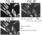
- the hard secondary phase (retained austenite + fresh martensite) and the residual microstructure other than the above are identified in a microstructure image (see, for example, FIG. 2A ) as described above.
- the island regions of the hard secondary phase are extracted.
- circularity and aspect ratio of each extracted island region are determined using ImageJ, which is open source software.
- the aspect ratio of each island region is determined by elliptically approximating each island region using dividing the major axis diameter W of the approximated ellipse by the minor axis diameter L (W/L).
- FIG. 2B illustrates an example of the color-coded classification of each extracted island region of the hard secondary phase into MA1 and other.
- FIG. 2C illustrates an example of the color-coded classification of each extracted island region of the hard secondary phase into MA2 and other.
- a total area for island regions classified as either MA1 or MA2 is divided by the area of the observation region (25.6 ⁇ m ⁇ 17.6 ⁇ m), and multiplied by 100 (area fraction) for each of five fields of view.
- the average of the values (area fraction) for the five fields of view for each of MA1 and MA2 is then used as S MA1 and S MA2 , respectively.
- FIG. 2A, 2B, and 2C are each partial images extracted from one field of view of an observation region (25.6 ⁇ m ⁇ 17.6 ⁇ m) of a sample, as a reference for the above explanation.
- S ⁇ 2 /S ⁇ 1 is preferably 0.10 or more.
- the distribution of solute C concentration in retained austenite preferably has a sufficiently long tail to the side of high C concentration.
- S ⁇ 2 /S ⁇ 1 is an effective index for comprehensively evaluating the tail length of the distribution of solute C concentration in retained austenite to the side of high C concentration.
- S ⁇ 2 /S ⁇ 1 is 0.10 or more, particularly excellent strain hardenability in the high strain range is obtainable.
- S ⁇ 2 /S ⁇ 1 is preferably 0.10 or more.
- S ⁇ 2 /S ⁇ 1 is more preferably 0.12 or more.
- S ⁇ 2 /S ⁇ 1 is even more preferably 0.14 or more.
- An upper limit of S ⁇ 2 /S ⁇ 1 is not particularly limited. However, when a certain amount of retained austenite with relatively low solute C concentration is not present, the effect of improving strain hardenability in the high strain range may be small. Therefore, S ⁇ 2 /S ⁇ 1 is preferably 0.70 or less. S ⁇ 2 /S ⁇ 1 is more preferably 0.60 or less.
- a two-dimensional distribution of C concentration in the base steel sheet is measured in five fields of view using a field emission electron probe microanalyzer (FE-EPMA).
- the measurement by FE-EPMA is performed after finish polishing, before etching.
- the FE-EPMA measurement may be performed with a wider field of view, and the same field of view region (25.6 ⁇ m ⁇ 17.6 ⁇ m) may be extracted from the microstructure image in a later procedure.
- the quantitative precision of the two-dimensional distribution of C concentration is 0.020 % or less, and the resolution is 0.10 ⁇ m or less.
- the step size is 0.05 ⁇ m, and the same step size is used in all five fields of view to perform point analysis of C concentration in a uniform grid pattern across the entire field of view. Then, the data for each measurement point of C concentration is integrated for the five fields of view. Then, from the data of the entire integrated measurement range, the number of measurement points where C concentration is 0.70 % or more is determined. The number of measurement points where C concentration is 0.70 % or more is then divided by the total number of measurement points in the entire integrated measurement range, and multiplied by 100 (area fraction) to determine S ⁇ 1 . In the same way, S ⁇ 2 is determined from the number of measurement points where C concentration is 0.85 % or more.
- the measurement point data in the area occupied by such a high C concentration microstructure is substituted with a negative value (for example, -1). This excludes the measurement point data in high C concentration microstructure from the number of measurement points having C concentrations of 0.70 % or more and 0.85% or higher.
- Ferrite, bainitic ferrite, tempered martensite, and fresh martensite have lower C concentrations than retained austenite. Therefore, the measurement point data in the above phases (ferrite, bainitic ferrite, tempered martensite and fresh martensite) are excluded from the number of measurement points where C concentration is actually 0.70 % or more and 0.85 % or more.
- diffusible hydrogen content is preferably 0.50 mass ppm or less.
- Diffusible hydrogen content of base steel sheet 0.50 mass ppm or less
- diffusible hydrogen content of the base steel sheet is preferably 0.50 mass ppm or less. Further, the diffusible hydrogen content of the base steel sheet is more preferably 0.35 mass ppm or less. A lower limit of the diffusible hydrogen content of the base steel sheet is not particularly specified and may be 0 mass ppm. Further, in view of production technology constraints, the diffusible hydrogen content of the base steel sheet is preferably 0.01 mass ppm or more.
- the diffusible hydrogen content of the base steel sheet is measured as follows.
- a test piece 30 mm long and 5 mm wide is taken from a galvanized steel sheet, and the galvanized layer is removed with alkali. Then, an amount of hydrogen released from the test piece is measured by a thermal desorption analysis method. Specifically, the test piece is continuously heated from room temperature to 300 °C at a heating rate of 200 °C/h, and then cooled to room temperature. At this time, the amount of hydrogen released from the test piece in the temperature range from room temperature to 210 °C during the continuous heating is measured (cumulative hydrogen amount). The measured hydrogen amount is then divided by the mass of the test piece (after removal of the galvanized layer, before continuous heating), and a value converted to mass ppm units is the diffusible hydrogen content of the base steel sheet.
- a test piece is cut from the product under a typical operating environment and the diffusible hydrogen content of the base steel sheet portion is measured as described above.
- the diffusible hydrogen content of the base steel sheet of the galvanized steel sheet at a material stage before the forming or joining may also be considered to be 0.50 mass ppm or less.
- the tensile strength of the galvanized steel sheet according to an embodiment of the present disclosure is 590 MPa or more.
- the tensile strength of the galvanized steel sheet according to an embodiment of the present disclosure is preferably less than 1180 MPa.
- the elongation after fracture (T-El), strain hardening index in the low strain range (n 1 ), and strain hardening index in the high strain range (n 2 ) of the galvanized steel sheet according to an embodiment of the present disclosure are as described above.
- tensile strength (TS), elongation after fracture (T-El), strain hardening index in the low strain range (n 1 ), and strain hardening index in the high strain range (n 2 ) are measured as described below in the EXAMPLES section.
- the galvanized layer of the galvanized steel sheet according to an embodiment of the present disclosure may be provided on only one surface of the base steel sheet, and may be provided on both surfaces.
- the galvanized layer here refers to a coating layer in which Zn is the main component (Zn content of 50 % or more), for example, a hot-dip galvanized layer or a galvannealed layer.
- the hot-dip galvanized layer being composed of Zn, Fe: 20 mass% or less, and Al: 0.001 mass% or more and 1.0 mass% or less is preferred.
- the hot-dip galvanized layer may optionally contain one or more elements selected from the group consisting of Pb, Sb, Si, Sn, Mg, Mn, Ni, Cr, Co, Ca, Cu, Li, Ti, Be, Bi, and REM, totaling 0 mass% or more and 3.5 mass% or less.
- the Fe content of the hot-dip galvanized layer is more preferably less than 7 mass%. Other than the above elements, the balance is inevitable impurity.
- the galvannealed layer being composed of Zn, Fe: 20 mass% or less, and Al: 0.001 mass% or more and 1.0 mass% or less is preferred.
- the galvannealed layer may optionally contain one or more elements selected from the group consisting of Pb, Sb, Si, Sn, Mg, Mn, Ni, Cr, Co, Ca, Cu, Li, Ti, Be, Bi, and REM, totaling 0 mass% or more and 3.5 mass% or less.
- the Fe content of the galvannealed layer is more preferably 7 mass% or more.
- the Fe content of the galvannealed layer is even more preferably 8 mass% or more.
- the Fe content of the galvannealed layer is more preferably 15 mass% or less.
- the Fe content of the galvannealed layer is even more preferably 12 mass% or less.
- the balance is inevitable impurity.
- coating weight per side of the galvanized layer is not particularly limited.
- the coating weight per side of the galvanized layer is preferably 20 g/m 2 to 80 g/m 2 .
- the coating weight of the galvanized layer is measured as follows.
- a coating solution is prepared by adding 0.6 g of a corrosion inhibitor for Fe ("IBIT ® 700BK" (IBIT is a registered trademark in Japan, other countries, or both) manufactured by Asahi Chemical Co., Ltd.) to 1 L of a 10 mass% hydrochloric acid aqueous solution. Then, the galvanized steel sheet to be the test piece is immersed in the coating solution to dissolve the galvanized layer. Mass loss of the test piece before and after dissolving is measured, and the value is divided by the surface area of the base steel sheet (surface area of a coated portion) to calculate the coating weight (g/m 2 ).
- a corrosion inhibitor for Fe (“IBIT ® 700BK” (IBIT is a registered trademark in Japan, other countries, or both) manufactured by Asahi Chemical Co., Ltd.)
- the thickness of the galvanized steel sheet according to an embodiment of the present disclosure is not particularly limited.
- the thickness of the galvanized steel sheet is preferably 0.3 mm or more.
- the thickness of the galvanized steel sheet is preferably 3.0 mm or less.
- the member according to an embodiment of the present disclosure is a member produced using the galvanized steel sheet described above as a material.
- the material, the galvanized steel sheet is subjected to at least one of forming or joining to produce the member.
- the galvanized steel sheet has a TS of 590 MPa or more and excellent formability. Therefore, the member according to an embodiment of the present disclosure is particularly suitable for application as a complex-shape member for use in the automobile field.
- each temperature above refers to a surface temperature of the steel slab or the steel sheet.
- a steel slab having the chemical composition described above is prepared.
- steel material is melted to produce molten steel having the chemical composition described above.
- the steelmaking method is not particularly limited, and any known steelmaking method may be used, such as using a converter, electric furnace, and the like. Obtained molten steel is then solidified into a steel slab.
- the method of obtaining a steel slab from molten steel is not particularly limited. For example, continuous casting, ingot casting, and thin slab casting methods may be used. A continuous casting method is preferred from the viewpoint of hindering macro-segregation.
- the steel slab is then hot rolled to produce a hot-rolled steel sheet.
- An energy saving process may be applied to the hot rolling.
- Energy saving processes include hot charging (where a steel slab is charged into a heating furnace as a warm slab without cooling to room temperature and then hot rolled) and direct rolling (where a steel slab is hot rolled immediately after holding for a short period).
- hot rolling conditions there are no particular limitations on hot rolling conditions.
- hot rolling may be performed under the following conditions.
- the steel slab is temporarily cooled to room temperature and then reheated before rolling.
- the slab heating temperature (reheating temperature) is preferably 1100 °C or more in view of carbide dissolution and reduced rolling load.
- the slab heating temperature is preferably 1300 °C or less, in order to prevent increased scale loss.
- the slab heating temperature is based on the temperature of the steel slab surface.
- the steel slab is then subjected to rough rolling according to a conventional method to produce a rough-rolled sheet (hereinafter also referred to as a sheet bar).
- the sheet bar is then subjected to finish rolling to produce a hot-rolled steel sheet.
- the rolling finish temperature is preferably the Ar 3 transformation temperature or more, in order to reduce rolling load.
- the rolling finish temperature is preferably the Ar 3 transformation temperature or more because a high rolling reduction rate in an un-recrystallized state of austenite may result in the development of an abnormal microstructure elongated in the rolling direction, which may reduce the workability of the annealed sheet.
- the Ar 3 transformation temperature is determined by the following expression.
- Ar 3 ° C 868 ⁇ 396 ⁇ C % + 25 ⁇ Si % ⁇ 68 Mn %
- the [element symbol %] in the above expression represents the content (mass%) of the element in the chemical composition of the base steel sheet.
- Sheet bars may be joined together during hot rolling, and finish rolling may be performed continuously. Further, the sheet bar may be temporarily coiled before finish rolling. Further, at least part of finish rolling may be conducted as lubrication rolling to reduce rolling load in the hot rolling. Conducting lubrication rolling in such a manner is effective from the perspective of making the shape and material properties of the steel sheet uniform.
- the frictional coefficient is preferably 0.10 or more. The frictional coefficient is preferably 0.25 or less.
- the rolling finish temperature is preferably 800 °C or more.
- the rolling finish temperature is preferably 950 °C or less.
- the rolling finish temperature being 800 °C or more makes the steel microstructure at the hot-rolled steel sheet stage and, consequently, the steel microstructure of the final product more likely to be uniform. Uneven steel microstructure tends to reduce bendability.
- the rolling finish temperature is more than 950 °C, the amount of oxide (scale) formation increases. As a result, an interface between the steel substrate and oxide may be roughened, and the surface quality of the steel sheet after pickling and cold rolling may deteriorate. Further, coarse crystal grains may also cause a reduction in the strength and bendability of a steel sheet.
- the hot-rolled steel sheet is coiled.
- the coiling temperature is preferably 450 °C or more.
- the coiling temperature is preferably 750 °C or less.
- the hot-rolled steel sheet is optionally pickled.
- Pickling may remove oxides from the steel sheet surface, securing good chemical convertibility and coating or plating quality. Pickling may be performed in one or more batches. Pickling conditions are not particularly limited, and a conventional method may be followed.
- Cold rolling is performed by multi-pass rolling that requires two or more passes, for example, tandem-type multi-stand rolling, reverse rolling and the like.
- the rolling reduction of the cold rolling is not particularly limited.
- the rolling reduction of the cold rolling is preferably 20 % or more.
- the rolling reduction of the cold rolling is preferably 80 % or less.
- the rolling reduction of the cold rolling is less than 20 %, coarsening and non-uniformity of the steel microstructure is more likely to occur during the annealing, which may result in reduced strength and workability in the final product.
- the rolling reduction of the cold rolling exceeds 80 %, the steel sheet may be prone to shape defects and the coating weight of the galvanized coating may become uneven.
- the cold-rolled steel sheet obtained after cold rolling may be subjected to pickling.
- the cold-rolled steel sheet obtained as described above is annealed at an annealing temperature of 760 °C or more and 900 °C or less, for an annealing time of 20 s or more.
- the number of annealing cycles may be two or more, but one is preferred from the viewpoint of energy efficiency.
- Annealing temperature 760 °C or more and 900 °C or less
- the annealing temperature is less than 760 °C, the ratio of austenite formation during heating in the two-phase region of ferrite and austenite becomes insufficient, and the area fractions of bainitic ferrite and retained austenite are reduced. As a result, ductility, strain hardenability in the low strain range, and strain hardenability in the high strain range are reduced. Further, area fraction of ferrite and S F + S BF increase. Further, achieving a TS of 590 MPa or more becomes difficult. On the other hand, when the annealing temperature exceeds 900 °C, the ratio of austenite formation during heating in the two-phase region of ferrite and austenite becomes excessive. This reduces Mn concentration in austenite.
- the annealing temperature is therefore 760 °C or more and 900 °C or less.
- the annealing temperature is preferably 780 °C or more. Further, the annealing temperature is preferably 880 °C or less.
- the annealing temperature is the maximum arrival temperature during the annealing.
- Annealing time 20 s or more
- the annealing time is less than 20 s, the ratio of austenite formation during heating in the two-phase region of ferrite and austenite becomes insufficient, and the area fractions of bainitic ferrite and retained austenite are reduced. As a result, ductility, strain hardenability in the low strain range, and strain hardenability in the high strain range are reduced. Further, area fraction of ferrite and S F + S BF increase. Accordingly, achieving a TS of 590 MPa or more may become difficult.
- the annealing time is therefore 20 s or more.
- An upper limit of the annealing time is not particularly limited.
- the annealing time is preferably 900 s or less.
- the annealing time is a holding time in a temperature range from (annealing temperature - 40 °C) or more to the annealing temperature or less. That is, the annealing time includes not only the holding time at the annealing temperature, but also the time in the temperature range from (annealing temperature - 40 °C) or more to the annealing temperature or less during heating and cooling before and after reaching the annealing temperature.
- the cold-rolled steel sheet annealed as described above is cooled to the first cooling stop temperature of 350 °C or more and 550 °C or less.
- First cooling stop temperature T 0 350 °C or more and 550 °C or less
- the area fraction of tempered martensite increases excessively and the area fraction of bainitic ferrite, the area fraction of retained austenite, and S MA1 are reduced.
- ductility, strain hardenability in the low strain range, and strain hardenability in the high strain range are reduced.
- untransformed austenite decomposes into pearlite and carbides, and S MA2 is reduced. This may reduce strain hardenability in the high strain range.
- the first cooling stop temperature exceeds 550 °C, the amount of bainitic ferrite formed in the subsequent first holding decreases and S MA1 decreases. Further, as S MA1 decreases, S MA2 also decreases.
- the first cooling stop temperature is therefore 350 °C or more and 550 °C or less.
- the first cooling stop temperature is preferably 380 °C or more.
- the first cooling stop temperature is preferably 520 °C or less.
- the cold-rolled steel sheet is held at the temperature range from 350 °C or more to 550 °C or less (hereinafter also referred to as the first holding temperature range) for 3 s or more to 600 s or less.
- Holding time in first holding temperature range: 3 s or more to 600 s or less
- bainitic ferrite is formed and C diffusion from formed bainitic ferrite to untransformed austenite adjacent to the bainitic ferrite occurs. As a result, defined amounts for the area fraction of retained austenite and S MA1 are secured.
- the holding time in the first holding temperature range is therefore 3 s or more to 600 s or less.
- the holding time in the first holding temperature range is preferably 5 s or more.
- the holding time in the first holding temperature range is more preferably 10 s or more.
- the holding time in the first holding temperature range is preferably less than 200 s.
- the holding time in the first holding temperature range is more preferably less than 80 s.
- the holding time in the first holding temperature range includes the time the cold-rolled steel sheet remains in the temperature range until reaching the first cooling stop temperature in the first cooling, and the time the cold-rolled steel sheet remains in the temperature range until the start of galvanizing treatment in the coating described below (for example, the time the cold-rolled steel sheet remains in the temperature range until dipped into the galvanizing bath).
- the holding time in the first holding temperature range does not include the time in the temperature range of the galvanized steel sheet after applying the galvanizing treatment in the coating.
- the cold-rolled steel sheet is then subjected to a galvanizing treatment to produce a galvanized steel sheet.
- the galvanizing treatment include hot-dip galvanizing treatment and galvannealing treatment.
- coating bath temperature the relationship between the first cooling stop temperature in the first cooling and the temperature of the galvanizing bath in the galvanizing treatment (hereinafter also referred to as coating bath temperature) needs to satisfy the following Expression (1): ⁇ 120 ° C ⁇ T 0 ⁇ T 1 ⁇ 80 ° C
- T 0 is the first cooling stop temperature (°C) and T 1 is the temperature of the galvanizing bath in the galvanizing treatment (°C).
- T 0 - T 1 is less than -120 °C, S MA1 decreases in the subsequent coating, and strain hardenability in the low strain range and strain hardenability in the high strain range are reduced.
- T 0 - T 1 exceeds 80 °C, S MA2 and S ⁇ 2 /S ⁇ 1 decrease and strain hardenability in the high strain range decreases.
- T 0 - T 1 is preferably -80 °C or more.
- T 0 - T 1 is more preferably -70 °C or more.
- T 0 - T 1 is preferably 60 °C or less.
- T 0 - T 1 is more preferably 50 °C or less.
- Conditions other than the above are not particularly limited, and a conventional method may be used.
- the coating bath temperature is 440 °C or more and 500 °C or less.
- a galvanizing bath there is no particular limitation as long as the composition of the galvanized layer is as described above.
- a coating bath having an Al content of 0.10 mass% or more and 0.23 mass% or less with the balance being Zn and inevitable impurity is preferable.
- the galvanized steel sheet is preferably heated to an alloying temperature of 450 °C or more and 600 °C or less and subjected to an alloying treatment.
- the alloying temperature is less than 450 °C, the Zn-Fe alloying rate becomes slow and alloying may be difficult.
- the alloying temperature exceeds 600 °C, untransformed austenite may transform to pearlite, and TS, ductility, strain hardenability in the low strain range, and strain hardenability in the high strain range may decrease.
- the alloying temperature is more preferably 470 °C or more.
- the alloying temperature is more preferably 570 °C or less.
- the coating weight for both a hot-dip galvanized steel sheet (GI) and a galvannealed steel sheet (GA) is preferably 20 g/m 2 to 80 g/m 2 per side.
- the coating weight may be adjusted by gas wiping and the like.
- Additional holding may be performed before the second cooling described below and after or during the coating, in which the galvanized steel sheet is held at a temperature range from 280 °C or more to 550 °C or less (hereinafter also referred to as the additional holding temperature range) for 3 s or more to 600 s or less.
- the additional holding may be performed during the coating, that is, the coating may also serve as the additional holding.
- the total of the holding time in the first holding temperature range and the holding time in the additional holding temperature range is preferably 3 s or more to 600 s or less, and the total of the holding time in the additional holding temperature range and the holding time in the second temperature range is preferably 3 s or more to 2000 s or less.
- the total of the holding time in the first holding temperature range and the holding time in the additional holding temperature range is more preferably less than 200 s.
- the total of the holding time in the additional holding temperature range and the holding time in the second holding temperature range is more preferably less than 1200 s.
- the galvanized steel sheet is then cooled to the second cooling stop temperature of 280 °C or more and 470 °C or less.
- Second cooling stop temperature 280 °C or more and 470 °C or less
- the second cooling is required to change the morphology of untransformed austenite and promote C enrichment in untransformed austenite by forming an appropriate amount of bainitic ferrite in the second holding, and thereby control S MA2 and S ⁇ 2 /S ⁇ 1 to within a defined range.
- the second cooling stop temperature is less than 280 °C
- an appropriate amount of bainitic ferrite is not formed in the subsequent second holding, and S MA2 and S ⁇ 2 /S ⁇ 1 decrease, and strain hardenability in the high strain range decreases. Further, hard fresh martensite and self-tempered martensite increase and ductility decreases.
- the second cooling stop temperature is therefore 280 °C or more and 470 °C or less.
- the second cooling stop temperature is preferably 300 °C or more. Further, the second cooling stop temperature is preferably 450 °C or less. 0 ° C ⁇ T 0 ⁇ T 2
- the second cooling stop temperature is required to be the first cooling stop temperature or less, that is, Expression (2) above needs to be satisfied.
- T 0 - T 2 is preferably 20 °C or more. T 0 - T 2 is more preferably 30 °C or more. An upper limit of T 0 - T 2 is not particularly limited. T 0 - T 2 is preferably 200 °C or less. T 0 - T 2 is more preferably 160 °C or less.
- T 0 is the first cooling stop temperature (°C) and T 2 is the second cooling stop temperature (°C).
- the galvanized steel sheet is held at the temperature range from 280 °C or more to 470 °C or less (hereinafter also referred to as the second holding temperature range) for 10 s or more to 2000 s or less.
- Holding time in second holding temperature range: 10 s or more to 2000 s or less
- the holding time in the second holding temperature range is therefore 10 s or more to 2000 s or less.
- the holding time in the second holding temperature range is preferably 15 s or more.
- the holding time in the second holding temperature range is preferably 1200 s or less.
- the holding time in the second holding temperature range includes the time the galvanized steel sheet remains in the second holding temperature range after reaching the second cooling stop temperature as well as the time the galvanized steel sheet remains in the second holding temperature range until reaching the second cooling stop temperature in the second cooling.
- Cooling conditions after holding in the second holding temperature range are not particularly limited, and a conventional method may be followed.
- gas jet cooling, mist cooling, roll-chilling, water cooling, air cooling, and the like may be applied as a cooling method.
- cooling to 50 °C or less is preferable. Cooling to about room temperature is more preferable. For example, an average cooling rate of 1 °C/s or more and 50 °C/s or less in cooling after holding in the second holding temperature range is preferred.
- the galvanized steel sheet obtained as described above may be further subjected to temper rolling.
- the rolling reduction of the temper rolling exceeds 2.00 %, yield stress may increase and dimensional accuracy may decrease when forming the galvanized steel sheet into a member. Therefore, the rolling reduction of the temper rolling is preferably 2.00 % or less.
- a lower limit of the rolling reduction of the temper rolling is not particularly limited. From the viewpoint of productivity, the rolling reduction of the temper rolling is preferably 0.05 % or more.
- the temper rolling may be performed on equipment that is continuous (on-line) with the annealing equipment used to perform each of the aforementioned processes, and may be performed on equipment that is discontinuous (off-line) with the annealing equipment used to perform each of the processes.
- the number of rolling cycles for the temper rolling may be one, two, or more. Processing by a leveler or the like is also acceptable, as long as an equivalent elongation rate to temper rolling is provided.
- Conditions other than those described above are not particularly limited, and a conventional method may be used.
- the method of producing a member according to an embodiment of the present disclosure includes applying at least one of forming or joining to the galvanized steel sheet described above (for example, a galvanized steel sheet produced by the method of producing a galvanized steel sheet) to produce a member.
- a forming method is not particularly limited, and a typical processing method such as press working may be used, for example.
- a joining method is also not particularly limited, and for example, typical welding such as spot welding, laser welding, arc welding, and the like, rivet joining, swaging joining, and the like may be used.
- Forming and joining conditions are not particularly limited and may follow a conventional method.
- Steel material having the chemical compositions listed in Table 1 (the balance being Fe and inevitable impurity) was melted in a converter and made into steel slabs by a continuous casting method.
- the obtained steel slabs were heated to 1250 °C. After heating, the steel slabs were hot rolled, consisting of rough rolling and finish rolling, to produce hot-rolled steel sheets.
- the hot-rolled steel sheets were then pickled and cold rolled (rolling reduction: 50 %) to produce cold-rolled steel sheets having the thicknesses listed in Table 3.
- the obtained cold-rolled steel sheets were then subjected to the annealing, the first cooling, the first holding, the coating, the second cooling, and the second holding under conditions listed in Table 2 to obtain galvanized steel sheets.
- hot-dip galvanizing treatment or galvannealing treatment was performed to obtain hot-dip galvanized steel sheets (hereinafter also referred to as GI) or galvannealed steel sheets (hereinafter also referred to as GA).
- GI hot-dip galvanized steel sheets
- GA galvannealed steel sheets
- a galvanizing bath was used that had a composition of Al: 0.20 mass%, with the balance being Zn and inevitable impurity.
- a coating bath was used that had a composition of Al: 0.14 mass%, with the balance being Zn and inevitable impurity.
- the coating weight was 45 g/m 2 to 72 g/m 2 per side when producing GI and 45 g/m 2 per side when producing GA.
- the composition of the galvanized layer of the final galvanized steel sheet in the case of GI was Fe: 0.1 mass% to 1.0 mass% and Al: 0.2 mass% to 1.0 mass%, with the balance being Zn and inevitable impurity.
- the composition was Fe: 7 mass% to 15 mass% and Al: 0.1 mass% to 1.0 mass%, with the balance being Zn and inevitable impurity.
- Galvanized layers were formed on both sides of the base steel sheet.
- tensile strength (TS), elongation after fracture (T-El), strain hardening index in the low strain range (n 1 ), and strain hardening index in the high strain range (n 2 ) were evaluated according to the following criteria by conducting tensile testing and strain hardening index testing as follows.
- Tensile testing and strain hardening index testing were performed in accordance with JIS Z 2241 and JIS Z 2253. That is, a JIS No. 5 test piece was taken from the obtained galvanized steel sheet such that the longitudinal direction was perpendicular to the rolling direction of the base steel sheet. The collected test piece was subjected to tensile testing at a crosshead speed of 10 mm/min to measure TS, T-El, U-El, n 1 , and n 2 .
- n 1 was calculated by a two-point method from the strain and test force (stress) values at which the strain was 0.40 times and 0.80 times the uniform elongation (U-El).
- n 2 was calculated by a two-point method from the strain and test force (stress) values at which the strain was 0.90 times and 0.95 times the uniform elongation (U-El). The results are listed in Table 4.
- tensile strength (TS), elongation after fracture (T-El), strain hardening index in the low strain range (m), and strain hardening index in the high strain range (n 2 ) were all acceptable in each of the Examples. Further, tensile strength (TS), elongation after fracture (T-El), strain hardening index in the low strain range (m), and strain hardening index in the high strain range (n 2 ) were all excellent for the members obtained by forming and the members obtained by joining using the steel sheets of the Examples.
- TS tensile strength
- T-El elongation after fracture
- n 1 strain hardening index
- n 2 strain hardening index in the high strain range
Landscapes
- Chemical & Material Sciences (AREA)
- Engineering & Computer Science (AREA)
- Materials Engineering (AREA)
- Mechanical Engineering (AREA)
- Metallurgy (AREA)
- Organic Chemistry (AREA)
- Thermal Sciences (AREA)
- Physics & Mathematics (AREA)
- Chemical Kinetics & Catalysis (AREA)
- Crystallography & Structural Chemistry (AREA)
- Oil, Petroleum & Natural Gas (AREA)
- Heat Treatment Of Sheet Steel (AREA)
- Coating With Molten Metal (AREA)
Abstract
Description
- The present disclosure relates to a galvanized steel sheet, a member made from the galvanized steel sheet, and methods of producing same.
- In recent years, enhancement of fuel efficiency of automobiles has become an important issue from the viewpoint of protecting the global environment. Therefore, there is a growing trend to reduce weight of automobile bodies by increasing strength and reducing thickness of steel sheets used as material of automobile members.
- Further, in view of automotive body rust resistance, steel sheets used as material of automobile members are often galvanized. Therefore, development of galvanized steel sheets having high strength is also progressing.
- As an example of a steel sheet used as a material of an automobile member, Patent Literature (PTL) 1 describes:
"A high strength hot-dip galvanized steel sheet having excellent formability, comprising: a chemical composition of steel containing, in mass%, C: 0.05 % to 0.3 %, Si: more than 0.60 % to 2.0 %, Mn: 0.50 % to 3.50 %, P: 0.003 % to 0.100 %, S: 0.010 % or less, Al: 0.010 % to 0.06 %, and N: 0.007 % or less, with the balance being Fe and inevitable impurity; and the steel sheet microstructure including ferrite at an area fraction of 20 % or more, tempered martensite, tempered bainite, and bainite at a total area fraction of 10 % or more, and ferrite, tempered martensite, tempered bainite, and bainite at a total area fraction of 90 % or more, wherein standard deviation of nano-hardness is 1.50 GPa or less." - PTL 2 describes:
"A cold-rolled steel sheet comprising: - a chemical composition containing, in mass%,
- C: more than 0.010 % and less than 0.080 %,
- Si: more than 0.55 % and 2.00 % or less,
- Mn: more than 1.50 % and 3.50 % or less,
- sol.Al: more than 0.10 % and less than 1.00 %,
- Nb: 0.001 % or more and less than 0.100 %,
- Ti: 0 % to less than 0.100 %,
- V: 0 % to 0.50 %,
- Cr: 0 % to 1.0 %,
- Mo: 0 % to 0.50 %,
- B: 0 % to 0.010 %,
- Ca: 0 % to 0.010 %,
- Mg: 0 % to 0.010 %,
- REM: 0 % to 0.050 %,
- Bi: 0 % to 0.050 %,
- with the balance being Fe and impurities,
- among the impurities, P, S and N are
- P: 0.10 % or less,
- S: 0.010 % or less, and
- N: 0.010 % or less,
- and the metallic microstructure including ferrite as the main phase and retained austenite in a second phase, wherein
- the volume fraction of ferrite to the total microstructure is 79 % or more,
- average grain size of ferrite is less than 5.0 µm, and
- the volume fraction of retained austenite to the total microstructure is more than 1.0 % and less than 7.0 % (excluding 3.0 % or less)."
- PTL 3 describes:
- "a high strength steel sheet having excellent ductility and hole expansion formability, comprising a chemical composition containing, in mass%, C: 0.05 % or more and 0.30 % or less, Si: 0.05 % or more and 6.00 % or less, Mn: 1.50 % or more and 10.00 % or less, P: 0.000 % or more and 0.100 % or less, S: 0.000 % or more and 0.010 % or less, sol.Al: 0.010 % or more and 1.000 % or less, N: 0.000 % or more and 0.010 % or less, Ti: 0.000 % or more and 0.200 % or less, Nb: 0.000 % or more and 0.200 % or less, V: 0.000 % or more and 0.200% or less, Cr: 0.000 % or more and 1.000 % or less, Mo: 0.000 % or more and 1.000 % or less, Cu: 0.000 % or more and 1.000 % or less, Ni: 0.000 % or more and 1.000 % or less, Ca: 0.0000 % or more and 0.0100 % or less, Mg: 0.0000 % or more and 0.0100 % or less, REM: 0.0000 % or more and 0.0100 % or less, Zr: 0.0000 % or more and 0.0100% or less, W: 0.0000 % or more and 0.0100 % or less, B: 0.0000 % or more and 0.0030 % or less, with the balance being Fe and inevitable impurity, wherein
- the steel sheet microstructure, in area fractions, consists of ferrite: 15 % or more and 80 % or less, and hard microstructure consisting of any one of bainite, martensite, retained austenite, or any combination thereof: 20 % or more and 85 % or less in total,
- an area fraction of the largest consolidated ferrite region in a region at a depth from the surface of 3/8t to t/2, where t is steel sheet thickness, is 80 % or more of the total ferrite area, and the two-dimensional isoperimetric constant of the largest consolidated ferrite region is 0.35 or less."
-
- PTL 1:
JP 5223360 B2 - PTL 2:
JP 6326837 B2 - PTL 3:
JP 6418363 B1 - Automobile members are often complex in shape, and the occurrence of forming defects such as cracks and wrinkles is a major problem when forming steel sheets into automobile members. Typically, forming defects are caused by strain localization. Therefore, steel sheets that are materials of automobile members are required to have not only high ductility to withstand deformation during forming, but also high strain hardenability to disperse strain. In particular, forming defects often occur after a steel sheet has been heavily deformed. Accordingly, a steel sheet is required to exhibit excellent strain hardenability over a wide strain range, and specifically, not only high strain hardenability in a low strain range, but also excellent strain hardenability in a high strain range.
- Typically, as a steel sheet is strengthened, ductility and strain hardenability are reduced. Therefore, even with the current trend toward higher strength automobile members, steel sheets having tensile strength (hereinafter also referred to as TS) of less than 590 MPa are still used for some automobile members. Further, even when steel sheets having TS of 590 MPa or more are used, the current situation is that localization of strain is prevented by adding a forming process, for example.
- The current situation calls for the development of a steel sheet having high strength, excellent ductility, and good strain hardenability in both low and high strain ranges.
- The steel sheets described in PTL 1-3 do not combine high strength, excellent ductility, and excellent strain hardenability over a wide strain range, and in particular, no consideration is given to strain hardenability in the high strain range.
- The present disclosure was developed in view of the above requirements, and it would be helpful to provide a galvanized steel sheet having high strength, excellent ductility, excellent strain hardenability in the low strain range, and excellent strain hardenability in the high strain range, together with an advantageous method of producing the galvanized steel sheet.
- It would also be helpful to provide a member made from the galvanized steel sheet and a method of producing the member.
- Here, high strength means that TS measured by tensile testing in accordance with Japanese Industrial Standard JIS Z 2241 satisfies the following expression.

- Excellent ductility means that elongation after fracture (hereinafter also referred to as T-El) measured by tensile testing in accordance with JIS Z 2241 satisfies an expression below, depending on the TS measured by the tensile testing.
- when 590 MPa ≤ TS < 780 MPa, 32.0 % ≤ T-El
- when 780 MPa ≤ TS < 980 MPa, 22.0 % ≤ T-El
- when 980 MPa ≤ TS, 16.0 % ≤ T-El
- Excellent strain hardenability in the low strain range means that a strain hardening index measured by a two-point method in accordance with JIS Z 2253, with the strain range from 0.4 × U-El to 0.8 × U-El, (hereinafter also referred to as n1) satisfies an expression below, depending on the TS measured according to the tensile test above.
- when 590 MPa ≤ TS < 780 MPa, 0.200 ≤ n1
- when 780 MPa ≤ TS < 980 MPa, 0.180 ≤ n1
- when 980 MPa ≤ TS, 0.120 ≤ n1
- Here, U-El is uniform elongation measured by a tensile test in accordance with JIS Z 2241.
- Excellent strain hardenability in the high strain range means that a strain hardening index measured by a two-point method in accordance with JIS Z 2253, with the strain range from 0.9 × U-El to 0.95 × U-El, (hereinafter also referred to as n2) satisfies an expression below, depending on the TS measured according to the tensile test above.
- when 590 MPa ≤ TS < 780 MPa, 0.180 ≤ n2
- when 780 MPa ≤ TS < 980 MPa, 0.140 ≤ n2
- when 980 MPa ≤ TS, 0.090 ≤ n2
- Here, U-El is uniform elongation measured by a tensile test in accordance with JIS Z 2241.
- The inventors conducted extensive studies to solve the technical problem outlined above. As a result, the inventors made the following discoveries.
- It is important to appropriately adjust a chemical composition of a base steel sheet of a galvanized steel sheet and steel microstructure of the base steel sheet of the galvanized steel sheet such that:
- area fraction of ferrite: 20.0 % or more and 90.0 % or less,
- area fraction of bainitic ferrite: 4.0 % or more and 60.0 % or less,
- area fraction of tempered martensite: 20.0 % or less, including 0 %,
- area fraction of retained austenite: 3.0 % or more,
- area fraction of fresh martensite: 20.0 % or less, including 0 %,
- SF + SBF: 55.0 % or more and 95.0 % or less,
- SMA1: 4.0 % or more, and
- SMA2: 1.5 % or more.
- This results in a galvanized steel sheet having high strength, excellent ductility, excellent strain hardenability in the low strain range, and excellent strain hardenability in the high strain range.
- Here,
- SF is area fraction of ferrite,
- SBF is area fraction of bainitic ferrite,
- SMA1 is area fraction of the sum of island regions of hard secondary phase consisting of retained austenite and fresh martensite having a circularity of 0.40 or less, and
- SMA2 is area fraction of the sum of island regions of the hard secondary phase having a circularity of 0.20 or less and an aspect ratio of 4.0 or less.
- The present disclosure is based on these discoveries and further studies.
- Primary features of the present disclosure are as follows.
- 1. A galvanized steel sheet comprising a base steel sheet and a galvanized layer on a surface of the base steel sheet, wherein
the base steel sheet comprises:- a chemical composition containing (consisting of), in mass%,
- C: 0.040 % or more and 0.200 % or less,
- Si: 0.20 % or more and 3.00 % or less,
- Mn: 1.00 % or more and less than 3.50 %,
- P: 0.001 % or more and 0.100 % or less,
- S: 0.0200 % or less,
- Al: 0.005 % or more and 2.000 % or less, and
- N: 0.0100 % or less,
- with the balance being Fe and inevitable impurity,
- the steel microstructure of the base steel sheet comprises:
- area fraction of ferrite: 20.0 % or more and 90.0 % or less,
- area fraction of bainitic ferrite: 4.0 % or more and 60.0 % or less,
- area fraction of tempered martensite: 20.0 % or less, including 0 %,
- area fraction of retained austenite: 3.0 % or more,
- area fraction of fresh martensite: 20.0 % or less, including 0 %,
- SF + SBF: 55.0 % or more and 95.0 % or less,
- SMA1: 4.0 % or more, and
- SMA2: 1.5 % or more, wherein
- tensile strength is 590 MPa or more,
- where
- SF is area fraction of ferrite,
- SBF is area fraction of bainitic ferrite,
- SMA1 is area fraction of the sum of island regions of hard secondary phase consisting of retained austenite and fresh martensite having a circularity of 0.40 or less, and
- SMA2 is area fraction of the sum of island regions of the hard secondary phase having a circularity of 0.20 or less and an aspect ratio of 4.0 or less.
- 2. The galvanized steel sheet according to 1, above, wherein the chemical composition of the base steel sheet further contains, in mass%, at least one selected from the group consisting of:
- Ti: 0.200 % or less,
- Nb: 0.200 % or less,
- V: 0.100 % or less,
- B: 0.0100 % or less,
- Cu: 1.000 % or less,
- Cr: 1.000 % or less,
- Ni: 1.000 % or less,
- Mo: 0.500 % or less,
- Sb: 0.200 % or less,
- Sn: 0.200 % or less,
- Ta: 0.100 % or less,
- W: 0.500 % or less,
- Mg: 0.0200 % or less,
- Zn: 0.0200 % or less,
- Co: 0.0200 % or less,
- Zr: 0.0200 % or less,
- Ca: 0.0200 % or less,
- Ce: 0.0200 % or less,
- Se: 0.0200 % or less,
- Te: 0.0200 % or less,
- Ge: 0.0200 % or less,
- As: 0.0200 % or less,
- Sr: 0.0200 % or less,
- Cs: 0.0200 % or less,
- Hf: 0.0200 % or less,
- Pb: 0.0200 % or less,
- Bi: 0.0200 % or less, and
- REM: 0.0200 % or less.
- 3. The galvanized steel sheet according to 1 or 2, above, wherein Sγ2/Sγ1 is 0.10 or more in the steel microstructure of the base steel sheet,
where- Sγ1 is area fraction of retained austenite having a solute C concentration of 0.70 % or more, and
- Sγ2 is area fraction of retained austenite having a solute C concentration of 0.85 % or more.
- 4. The galvanized steel sheet according to any one of 1 to 3, above, wherein diffusible hydrogen content of the base steel sheet is 0.50 mass ppm or less.
- 5. The galvanized steel sheet according to any one 1 to 4, above, wherein the galvanized layer is a hot-dip galvanized layer or a galvannealed layer.
- 6. A member made using the galvanized steel sheet according to any one of 1 to 5, above.
- 7. A method for manufacturing a galvanized steel sheet, the method comprising:
- hot rolling a steel slab having the chemical composition according to 1 or 2, above, to produce a hot-rolled steel sheet;
- cold rolling the hot-rolled steel sheet to produce a cold-rolled steel sheet;
- annealing the cold-rolled steel sheet at an annealing temperature of 760 °C or more and 900 °C or less for an annealing time of 20 s or more;
- cooling the cold-rolled steel sheet to a first cooling stop temperature of 350 °C or more and 550 °C or less;
- holding the cold-rolled steel sheet at a temperature range of 350 °C or more and 550 °C or less for 3 s or more to 600 s or less;
- coating the cold-rolled steel sheet by a galvanizing treatment to produce a galvanized steel sheet;
- cooling the galvanized steel sheet to a second cooling stop temperature of 280 °C or more and 470 °C or less; and
- holding the galvanized steel sheet at a temperature range of 280 °C or more and 470 °C or less for 10 s or more to 2000 s or less,
- wherein
- the first cooling stop temperature, temperature of a galvanizing bath in the galvanizing treatment, and the second cooling stop temperature satisfy the following Expression (1) and Expression (2)


- where
- T0 is the first cooling stop temperature in °C,
- T1 is the temperature of the galvanizing bath in the galvanizing treatment in °C, and
- T2 is the second cooling stop temperature in °C.
- 8. The method of producing a galvanized steel sheet according to 7, above, wherein the galvanizing treatment is a hot-dip galvanizing treatment or a galvannealing treatment.
- 9. A method of producing a member, wherein the galvanized steel sheet according to any one of 1 to 5, above, is subjected to at least one of a forming process or a joining process to produce the member.
- According to the present disclosure, a galvanized steel sheet having high strength, excellent ductility, excellent strain hardenability in the low strain range, and excellent strain hardenability in the high strain range is obtainable. Further, the galvanized steel sheet has high strength, excellent ductility, and excellent strain hardenability over a wide range of strain, making it extremely advantageous for use as a material for automobile members and the like that have complex shapes. A steel sheet that has excellent ductility and excellent strain hardenability over a wide range of strain also has excellent anti-crash property properties, and therefore the galvanized steel sheet according to the present disclosure may be very advantageously applied as a material for an impact energy absorbing member or the like of an automobile.
- In the accompanying drawings:
-
FIG. 1A is an example of a microstructure image from a scanning electron microscope (SEM) used for microstructure identification; -
FIG. 1B is the microstructure image ofFIG. 1A color-coded by phase using Adobe Photoshop by Adobe Systems Inc.; -
FIG. 2A is an example of a microstructure image from a SEM used for microstructure identification; -
FIG. 2B is the microstructure image ofFIG. 2A where among hard secondary phase (MA) island regions extracted, the island regions classified as MA1 and the island regions classified as other than MA1 are color-coded using Adobe Photoshop by Adobe Systems Inc.; and -
FIG. 2C is the microstructure image ofFIG. 2A where among hard secondary phase (MA) island regions extracted, the island regions classified as MA2 and the island regions classified as other than MA2 are color-coded using Adobe Photoshop by Adobe Systems Inc. - The following describes embodiments of the present disclosure.
- First, a chemical composition of a base steel sheet of a galvanized steel sheet according to an embodiment of the present disclosure is described. Hereinafter, although the unit in all chemical compositions is "mass%", this may be indicated simply as "%", unless otherwise specified.
- C is an element effective for securing TS of 590 MPa or more, high ductility, and strain hardenability by forming appropriate amounts of fresh martensite, bainitic ferrite, and retained austenite. Here, when C content is less than 0.040 %, an area fraction of ferrite increases, and achieving a TS of 590 MPa or more becomes difficult. Further, reduced ductility and strain hardenability may result. On the other hand, when the C content exceeds 0.200 %, retained austenite and fresh martensite increase excessively. As a result, voids are more likely to form during deformation, and ductility and strain hardenability in the high strain range are reduced.
- The C content is therefore 0.040 % or more and 0.200 % or less. The C content is preferably 0.060 % or more. The C content is more preferably 0.070 % or more. Further, the C content is preferably 0.170 % or less. The C content is more preferably 0.150 % or less.
- Si inhibits carbide formation and promotes formation of retained austenite. That is, Si is an element that affects the area fraction of retained austenite, SMA1, SMA2, and C concentration in the retained austenite. Here, Si content less than 0.20 % reduces the area fraction of retained austenite, SMA1, and SMA2, and reduces ductility, strain hardenability in the low strain range, and strain hardenability in the high strain range. Further, a decrease in Sγ2/Sγ1 may result. On the other hand, when the Si content exceeds 3.00 %, the area fraction of ferrite increases excessively and achieving a TS of 590 MPa or more becomes difficult. Further, C concentration in retained austenite increases excessively. As a result, voids are more likely to form during deformation, and ductility and strain hardenability in the high strain range are reduced.
- The Si content is therefore 0.20 % or more and 3.00 % or less. The Si content is preferably 0.40 % or more. The Si content is more preferably 0.50 % or more. Further, the Si content is preferably 2.00 % or less. The Si content is more preferably 1.90 % or less.
- Mn is an element that adjusts area fractions of ferrite, bainitic ferrite, and the like. Here, when Mn content is less than 1.00 %, the area fraction of ferrite increases excessively, and achieving a TS of 590 MPa or more becomes difficult. On the other hand, when the Mn content is 3.50 % or more, the area fractions of ferrite and bainitic ferrite decrease. Further, the area fraction of fresh martensite increases. As a result, the desired ductility and strain hardenability in the low strain range become unobtainable.
- The Mn content is therefore 1.00 % or more and less than 3.50 %. The Mn content is preferably 1.10 % or more. The Mn content is more preferably 1.40 % or more. Further, the Mn content is preferably less than 2.80 %. The Mn content is more preferably 2.50 % or less.
- P is an element that acts as a solid solution strengthener and increases steel sheet strength. To achieve this effect, P content is 0.001 % or more. On the other hand, when the P content exceeds 0.100 %, P segregates to prior austenite grain boundaries and embrittles the grain boundaries. As a result, voids are more likely to form during deformation, and ductility and strain hardenability in the high strain range are reduced.
- The P content is therefore 0.001 % or more and 0.100 % or less. The P content is preferably 0.030 % or less.
- S is present in steel as sulfide. In particular, when S content exceeds 0.0200 %, voids are more likely to form during deformation, and ductility and strain hardenability in the high strain range are reduced.
- The S content is therefore 0.0200 % or less. The S content is preferably 0.0080 % or less. A lower limit of the S content is not particularly specified. In view of production technology constraints, the S content is preferably 0.0001 % or more.
- Al inhibits carbide formation and promotes formation of retained austenite. That is, Al is an element that affects the area fraction of retained austenite, SMA1, SMA2, and Sγ2/Sγ1. To obtain these effects, Al content is 0.005 % or more. On the other hand, when the Al content exceeds 2.000 %, the area fraction of ferrite increases excessively, and achieving a TS of 590 MPa or more becomes difficult.
- The Al content is therefore 0.005 % or more and 2.000 % or less. The Al content is preferably 0.010 % or more. The Al content is more preferably 0.015 % or more. The Al content is even more preferably 0.020 % or more. Further, the Al content is preferably 1.000 % or less. The Al content is more preferably 0.900 % or less.
- N is present in steel as nitride. In particular, when N content exceeds 0.0100 %, steel sheet ultimate deformability is reduced. As a result, voids are more likely to form during deformation, and ductility and strain hardenability in the high strain range are reduced.
- The N content is therefore 0.0100 % or less. Further, the N content is preferably 0.0050 % or less. A lower limit of the N content is not particularly specified. In view of production technology constraints, the N content is preferably 0.0005 % or more.
- Basic composition of the base steel sheet of the galvanized steel sheet according to an embodiment of the present disclosure is described above. The base steel sheet of the galvanized steel sheet according to an embodiment of the present disclosure has a chemical composition containing the basic composition above, with the balance being Fe (iron) and inevitable impurity. Here, the base steel sheet of the galvanized steel sheet according to an embodiment of the present disclosure preferably has a chemical composition containing the basic composition above, with the balance being Fe and inevitable impurity. In addition to the above basic composition, the base steel sheet of the galvanized steel sheet according to an embodiment of the present disclosure may contain at least one of the components selected from the group listed below. The components listed below do not have a particular lower limit because the effect of the present disclosure is obtainable whenever content is equal to or less than the upper limit indicated below. When any of the following optional components are contained at less than a preferred lower limit described below, such a component is included as an inevitable impurity.
- Ti: 0.200 % or less,
- Nb: 0.200 % or less,
- V: 0.100 % or less,
- B: 0.0100 % or less,
- Cu: 1.000 % or less,
- Cr: 1.000 % or less,
- Ni: 1.000 % or less,
- Mo: 0.500 % or less,
- Sb: 0.200 % or less,
- Sn: 0.200 % or less,
- Ta: 0.100 % or less,
- W: 0.500 % or less,
- Mg: 0.0200 % or less,
- Zn: 0.0200 % or less,
- Co: 0.0200 % or less,
- Zr: 0.0200 % or less,
- Ca: 0.0200 % or less,
- Ce: 0.0200 % or less,
- Se: 0.0200 % or less,
- Te: 0.0200 % or less,
- Ge: 0.0200 % or less,
- As: 0.0200 % or less,
- Sr: 0.0200 % or less,
- Cs: 0.0200 % or less,
- Hf: 0.0200 % or less,
- Pb: 0.0200 % or less,
- Bi: 0.0200 % or less, and
- REM: 0.0200 % or less.
- Ti causes TS to increase due to formation of fine carbides, nitrides, and carbonitrides during hot rolling and annealing. To obtain this effect, Ti content is preferably 0.001 % or more. The Ti content is more preferably 0.005 % or more. On the other hand, when the Ti content exceeds 0.200 %, a large amount of coarse precipitates and inclusions may be formed. In such a case, when diffusible hydrogen is present in the steel sheet, coarse precipitates and inclusions as initiation points are likely to form voids during deformation, and ductility and strain hardenability in the high strain range are reduced. Therefore, when Ti is included, the Ti content is preferably 0.200 % or less. The Ti content is more preferably 0.060 % or less.
- Nb, like Ti, causes TS to increase due to formation of fine carbides, nitrides, and carbonitrides during hot rolling and annealing. To obtain this effect, Nb content is preferably 0.001 % or more. The Nb content is more preferably 0.005 % or more. On the other hand, when the Nb content exceeds 0.200 %, a large amount of coarse precipitates and inclusions may be formed. As a result, voids are more likely to form during deformation, and ductility and strain hardenability in the high strain range are reduced. Therefore, when Nb is included, the Nb content is preferably 0.200 % or less. The Nb content is more preferably 0.060 % or less.
- V, like Ti and Nb, causes TS to increase due to formation of fine carbides, nitrides, and carbonitrides during hot rolling and annealing. To obtain this effect, V content is preferably 0.001 % or more. The V content is more preferably 0.005 % or more. On the other hand, when the V content exceeds 0.100 %, a large amount of coarse precipitates and inclusions may be formed. As a result, voids are more likely to form during deformation, and ductility and strain hardenability in the high strain range are reduced. Therefore, when V is included, the V content is preferably 0.100 % or less. The V content is more preferably 0.060 % or less.
- B is an element that increases hardenability by segregating at austenite grain boundaries. Further, B is an element that inhibits ferrite formation and grain growth during cooling after annealing. To obtain these effects, B content is preferably 0.0001 % or more. The B content is more preferably 0.0002 % or more. On the other hand, when the B content exceeds 0.0100 %, cracking may occur inside the steel sheet during hot rolling, which may reduce ductility and strain hardenability in the high strain range of a steel sheet. Therefore, when B is included, the B content is preferably 0.0100 % or less. The B content is more preferably 0.0050 % or less.
- Cu is an element that increases hardenability. In particular, Cu is an element that is effective for adjusting the area fraction of hard fresh martensite and the like to a more preferred range, and thereby adjusting TS to a more preferred range. To obtain this effect, Cu content is preferably 0.005 % or more. The Cu content is more preferably 0.020 % or more. On the other hand, when the Cu content exceeds 1.000 %, the area fraction of fresh martensite increases excessively and TS becomes excessively high. Further, a large amount of coarse precipitates and inclusions may be formed. In such cases, when diffusible hydrogen is present in the steel sheet, coarse precipitates and inclusions may become initiation points for cracks during tensile testing. That is, a decrease in ductility and strain hardenability in the high strain range may be caused. Therefore, when Cu is included, the Cu content is preferably 1.000 % or less. The Cu content is more preferably 0.200 % or less.
- Cr is an element that increases hardenability, and Cr is an element effective for formation of retained austenite and fresh martensite. To obtain these effects, Cr content is preferably 0.0005 % or more. In particular, from a viewpoint of achieving a more preferred range of TS, the Cr content is more preferably 0.010 % or more. On the other hand, when the Cr content exceeds 1.000 %, the area fraction of hard fresh martensite may increase excessively, leading to a decrease in ductility and strain hardenability in the high strain range. Therefore, when Cr is included, the Cr content is preferably 1.000 % or less. Further, the Cr content is more preferably 0.250 % or less. The Cr content is even more preferably 0.100 % or less.
- Ni is an element that increases hardenability. Further, Ni is an element that is effective for adjusting the area fraction of retained austenite and fresh martensite to a more preferred range, and thereby adjusting TS to a more preferred range. To obtain this effect, Ni content is preferably 0.005 % or more. The Ni content is more preferably 0.020 % or more. On the other hand, when the Ni content exceeds 1.000 %, the area fraction of fresh martensite may increase excessively, leading to a decrease in ductility and strain hardenability in the high strain range. Further, a large amount of coarse precipitates and inclusions may be formed. In such cases, when diffusible hydrogen is present in the steel sheet, the coarse precipitates and inclusions may become initiation points of cracks when the steel sheet is worked, that is, ductility and strain hardenability in the high strain range may decrease. Therefore, when Ni is included, the Ni content is preferably 1.000 % or less. The Ni content is more preferably 0.800 % or less.
- Mo is an element that increases hardenability. Further, Mo is an effective element for forming retained austenite. To obtain these effects, Mo content is preferably 0.005 % or more. The Mo content is more preferably 0.010 % or more. The Mo content is even more preferably 0.030 % or more. On the other hand, when the Mo content exceeds 0.500 %, the area fraction of fresh martensite may increase excessively, leading to a decrease in ductility and strain hardenability in the high strain range. Therefore, when Mo is included, the Mo content is preferably 0.500 % or less. The Mo content is more preferably 0.450 % or less. The Mo content is even more preferably 0.400 % or less.
- Sb is an element effective for inhibiting diffusion of C in the vicinity of the steel sheet surface during annealing and for controlling the formation of a soft layer in the vicinity of the steel sheet surface. To obtain these effects, Sb content is preferably 0.002 % or more. The Sb content is more preferably 0.005 % or more. On the other hand, when the Sb content exceeds 0.200 %, a soft layer is not formed in the vicinity of the steel sheet surface, which may lead to a decrease in ductility. Therefore, when Sb is included, the Sb content is preferably 0.200 % or less. The Sb content is more preferably 0.020 % or less.
- Sn, like Sb, is an element effective for inhibiting the diffusion of C in the vicinity of the steel sheet surface during annealing and for controlling the formation of a soft layer in the vicinity of the steel sheet surface. To obtain these effects, Sn content is preferably 0.002 % or more. The Sn content is more preferably 0.005 % or more. On the other hand, when the Sn content exceeds 0.200 %, a soft layer is not formed in the vicinity of the steel sheet surface, which may lead to a decrease in ductility. Therefore, when Sn is included, the Sn content is preferably 0.200 % or less. The Sn content is more preferably 0.020 % or less.
- Ta, like Ti, Nb, and V, causes TS to increase due to formation of fine carbides, nitrides, and carbonitrides during hot rolling and annealing. Further, Ta is partially solid-soluble in Nb carbides and Nb carbonitrides to form composite precipitates such as (Nb, Ta) (C, N). This inhibits coarsening of precipitates and stabilizes strengthening by precipitation, resulting in improved TS. To obtain these effects, Ta content is preferably 0.001 % or more. On the other hand, when the Ta content exceeds 0.100 %, a large amount of coarse precipitates and inclusions may be formed. In such cases, when diffusible hydrogen is present in the steel sheet, coarse precipitates and inclusions may become initiation points for cracks when the steel sheet is worked. That is, a decrease in ductility and strain hardenability in the high strain range may be caused. Therefore, when Ta is included, the Ta content is preferably 0.100 % or less.
- W is an element effective for increasing hardenability and adjusting TS to a more preferred range. To obtain these effects, W content is preferably 0.001 % or more. The W content is more preferably 0.030 % or more. On the other hand, when the W content exceeds 0.500 %, the area fraction of hard fresh martensite may increase excessively, leading to a decrease in ductility and strain hardenability in the high strain range. Therefore, when W is included, the W content is preferably 0.500 % or less. The W content is more preferably 0.450 % or less. The W content is even more preferably 0.400 % or less.
- Mg is an effective element for spheroidizing the shape of inclusions such as sulfides and oxides to improve ductility and strain hardenability in the high strain range. To obtain these effects, Mg content is preferably 0.0001 % or more. On the other hand, when the Mg content exceeds 0.0200 %, a large amount of coarse precipitates and inclusions may be formed. In such cases, when diffusible hydrogen is present in the steel sheet, coarse precipitates and inclusions may become initiation points for cracks when the steel sheet is worked. That is, a decrease in ductility and strain hardenability in the high strain range may be caused. Therefore, when Mg is included, the Mg content is preferably 0.0200 % or less.
- Zn is an effective element for spheroidizing the shape of inclusions to improve ductility and strain hardenability in the high strain range. To obtain this effect, Zn content is preferably 0.0010 % or more. On the other hand, when the Zn content exceeds 0.0200 %, a large amount of coarse precipitates and inclusions may be formed. In such cases, when diffusible hydrogen is present in the steel sheet, coarse precipitates and inclusions may become initiation points for cracks when the steel sheet is worked. That is, a decrease in ductility and strain hardenability in the high strain range may be caused. Therefore, when Zn is included, the Zn content is preferably 0.0200 % or less.
- Co, like Zn, is an effective element for spheroidizing the shape of inclusions to improve ductility and strain hardenability in the high strain range. To obtain this effect, Co content is preferably 0.0010 % or more. On the other hand, when the Co content exceeds 0.0200 %, a large amount of coarse precipitates and inclusions may be formed. In such cases, when diffusible hydrogen is present in the steel sheet, coarse precipitates and inclusions may become initiation points for cracks when the steel sheet is worked. That is, a decrease in ductility and strain hardenability in the high strain range may be caused. Therefore, when Co is included, the Co content is preferably 0.0200 % or less.
- Zr, like Zn and Co, is an effective element for spheroidizing the shape of inclusions to improve ductility and strain hardenability in the high strain range. To obtain this effect, Zr content is preferably 0.0010 % or more. On the other hand, when the Zr content exceeds 0.0200 %, a large amount of coarse precipitates and inclusions may be formed. In such cases, when diffusible hydrogen is present in the steel sheet, coarse precipitates and inclusions may become initiation points for cracks when the steel sheet is worked. That is, a decrease in ductility and strain hardenability in the high strain range may be caused. Therefore, when Zr is included, the Zr content is preferably 0.0200 % or less.
- Ca is present in steel as inclusions. Here, when Ca content exceeds 0.0200 %, a large amount of coarse inclusions may be formed. In such cases, when diffusible hydrogen is present in the steel sheet, coarse inclusions may become initiation points for cracks when the steel sheet is worked. That is, a decrease in ductility and strain hardenability in the high strain range may be caused. Therefore, when Ca is included, the Ca content is preferably 0.0200 % or less. The Ca content is more preferably 0.0020 % or less. A lower limit of Ca content is not particularly limited. The Ca content is preferably 0.0005 % or more. Further, in view of production technology constraints, the Ca content is more preferably 0.0010 % or more.
- Ce, Se, Te, Ge, As, Sr, Cs, Hf, Pb, Bi, and REM are all effective elements for improving ductility and strain hardenability in the high strain range. To achieve these effects, content of each of Ce, Se, Te, Ge, As, Sr, Cs, Hf, Pb, Bi, and REM is preferably 0.0001 % or more. On the other hand, when the content of any one of Ce, Se, Te, Ge, As, Sr, Cs, Hf, Pb, Bi, or REM exceeds 0.0200 %, a large amount of coarse precipitates and inclusions may form. In such cases, when diffusible hydrogen is present in the steel sheet, coarse precipitates and inclusions may become initiation points for cracks when the steel sheet is worked. That is, a decrease in ductility and strain hardenability in the high strain range may be caused. Therefore, when at least one of Ce, Se, Te, Ge, As, Sr, Cs, Hf, Pb, Bi, or REM is included, the content thereof is preferably 0.0200 % or less.
- Elements other than those described above are Fe and inevitable impurity.
- That is, the base steel sheet of the galvanized steel sheet according to an embodiment of the present disclosure comprises:
- a chemical composition containing, in mass%,
- C: 0.040 % or more and 0.400 % or less,
- Si: 0.20 % or more and 3.00 % or less,
- Mn: 1.00 % or more and less than 3.50 %,
- P: 0.001 % or more and 0.100 % or less,
- S: 0.0200 % or less,
- Al: 0.010 % or more and 2.000 % or less, and
- N: 0.0100 % or less,
- and optionally at least one selected from the group consisting of
- Ti: 0.200 % or less,
- Nb: 0.200 % or less,
- V: 0.100 % or less,
- B: 0.0100 % or less,
- Cu: 1.000 % or less,
- Cr: 1.000 % or less,
- Ni: 1.000 % or less,
- Mo: 0.500 % or less,
- Sb: 0.200 % or less,
- Sn: 0.200 % or less,
- Ta: 0.100 % or less,
- W: 0.500 % or less,
- Mg: 0.0200 % or less,
- Zn: 0.0200 % or less,
- Co: 0.0200 % or less,
- Zr: 0.0200 % or less,
- Ca: 0.0200 % or less,
- Ce: 0.0200 % or less,
- Se: 0.0200 % or less,
- Te: 0.0200 % or less,
- Ge: 0.0200 % or less,
- As: 0.0200 % or less,
- Sr: 0.0200 % or less,
- Cs: 0.0200 % or less,
- Hf: 0.0200 % or less,
- Pb: 0.0200 % or less,
- Bi: 0.0200 % or less, and
- REM: 0.0200 % or less.
- with the balance being Fe and inevitable impurity.
- Steel microstructure of the base steel sheet of the galvanized steel sheet according to an embodiment of the present disclosure is described below.
- The steel microstructure of the base steel sheet of the galvanized steel sheet according to an embodiment of the present disclosure comprises:
- area fraction of ferrite: 20.0 % or more and 90.0 % or less,
- area fraction of bainitic ferrite: 4.0 % or more and 60.0 % or less,
- area fraction of tempered martensite: 20.0 % or less, including 0 %,
- area fraction of retained austenite: 3.0 % or more,
- area fraction of fresh martensite: 20.0 % or less, including 0 %,
- SF + SBF: 55.0 % or more and 95.0 % or less,
- SMA1: 4.0 % or more, and
- SMA2: 1.5 % or more.
- Here,
- SF is area fraction of ferrite,
- SBF is area fraction of bainitic ferrite,
- SMA1 is area fraction of the sum of island regions of hard secondary phase consisting of retained austenite and fresh martensite having a circularity of 0.40 or less, and
- SMA2 is area fraction of the sum of island regions of the hard secondary phase having a circularity of 0.20 or less and an aspect ratio of 4.0 or less.
- The reasons for each of these limitations are described below.
- Soft ferrite is a phase that improves ductility and strain hardenability in the low strain range. From the viewpoint of securing high ductility and excellent strain hardenability in the low strain range, the area fraction of ferrite is 20.0 % or more. The area fraction of ferrite is preferably 25.0 % or more. The area fraction of ferrite is more preferably 40.0 % or more. Further, from the viewpoint of securing a TS of 590 MPa or more, the area fraction of ferrite is 90.0% or less. The area fraction of ferrite is preferably 85.0 % or less. The area fraction of ferrite is more preferably 80.0 % or less.
- Bainitic ferrite is a phase formed after ferrite is formed and C, Mn, and the like are enriched in untransformed austenite. Further, bainitic ferrite is a useful phase for securing an appropriate amount of retained austenite and obtaining high Sγ2/Sγ1 by utilizing further C diffusion from bainitic ferrite to untransformed austenite. In addition, bainitic ferrite is a phase that breaks up and refines untransformed austenite, reduces circularity of untransformed austenite, and causes untransformed austenite to take a shape that facilitates C enrichment. That is, bainitic ferrite, as a phase that causes untransformed austenite to take a shape that facilitates C enrichment, is also an important phase to obtain the desired SMA1 and SMA2, as well as high Sγ2/Sγ1. The area fraction of bainitic ferrite is therefore 4.0 % or more. Further, the area fraction of bainitic ferrite is preferably 8.0 % or more. The area fraction of bainitic ferrite is more preferably 10.0 % or more. On the other hand, an excessive increase in the area fraction of bainitic ferrite instead decreases ductility. The area fraction of bainitic ferrite is therefore 60.0 % or less. Further, the area fraction of bainitic ferrite is preferably 40.0 % or less.
- Bainitic ferrite refers only to the phase of bainite that has a crystal structure equivalent to ferrite, and may have a form that encapsulates iron-based carbides, retained austenite, and the like. However, iron-based carbides and retained austenite encapsulated in bainitic ferrite are not counted as bainitic ferrite area. Bainite here includes both upper bainite and lower bainite.
- Tempered martensite has an intermediate hardness between soft ferrite and hard fresh martensite and the like, and is a phase for securing high strength. However, from the viewpoint of securing good ductility, the area fraction of tempered martensite is 20.0 % or less. A lower limit of the area fraction of tempered martensite is not particularly limited, and may be 0 %. The area fraction of tempered martensite, when 980 ≤ TS, is preferably 3.0 % or more and 15.0 % or less. Further, the area fraction of tempered martensite, when 590 MPa ≤ TS < 980 MPa, is preferably 5.0 % or less. The area fraction of tempered martensite, when 590 MPa ≤ TS < 980 MPa, is more preferably 0 %.
- Tempered martensite is martensite that has undergone tempering and includes self-tempered martensite.
- From the viewpoint of obtaining excellent ductility, excellent strain hardenability in the low strain range, and excellent strain hardenability in the high strain range, the area fraction of retained austenite is 3.0 % or more. The area fraction of retained austenite is preferably 3.5 % or more. The area fraction of retained austenite is more preferably 4.0 % or more. The area fraction of retained austenite is even more preferably 4.5 % or more. An upper limit of the area fraction of retained austenite is not particularly limited. The area fraction of retained austenite is preferably 20.0 % or less.
- From the viewpoint of ensuring excellent ductility and excellent strain hardenability in the high strain range, the area fraction of fresh martensite is 20.0 % or less. A lower limit of the area fraction of fresh martensite is not particularly limited, and may be 0 %. Further, the area fraction of fresh martensite is preferably 1.0 % or more.
- Fresh martensite is martensite as quenched (not tempered).
- The area fraction of residual microstructure other than described above is preferably 10.0 % or less. The area fraction of the residual microstructure is more preferably 5.0 % or less. Further, the area fraction of the residual microstructure may be 0 %.
- The residual microstructure is not particularly limited, and may include carbides such as pearlite, cementite encapsulated in bainite, and the like. The type of residual microstructure may be confirmed, for example, by observation with a scanning electron microscope (SEM).
- Here, the area fractions of ferrite, bainitic ferrite, tempered martensite, retained austenite, and fresh martensite are measured at a 1/4 sheet thickness position of the base steel sheet, as follows.
- A sample is cut from the base steel sheet such that a thickness cross-section parallel to the rolling direction of the base steel sheet becomes an observation plane. The observation plane of the sample is then mirror-polished using diamond paste. The observation plane of the sample is then polished using colloidal silica and etched with 3 vol% nital to reveal the microstructure.
- Then, five views of a 25.6 µm × 17.6 µm field of view of the observation plane of the sample are observed using a scanning electron microscope (SEM) at an accelerating voltage of 15 kV and 5,000× magnification.
- From an obtained microstructure image (see, for example,
FIG. 1A ), ferrite, bainitic ferrite, tempered martensite, retained austenite, and fresh martensite are identified as follows. - Ferrite: a black region, blocky in morphology. Further, almost no iron-based carbides are encapsulated. However, when iron-based carbides are encapsulated, the area of ferrite does not include the area of the iron-based carbides. The same is also true for bainitic ferrite and tempered martensite, which are described below.
- Bainitic ferrite: black to dark gray region, which may be blocky or irregular in morphology. Further, no or relatively few iron-based carbides are encapsulated.
- Tempered martensite: gray region, irregular in morphology. Further, a relatively large number of iron-based carbides are encapsulated.
- Hard secondary phase (retained austenite + fresh martensite): white to light gray region, irregular in morphology. Further, iron-based carbides are not encapsulated. When size is relatively large, the color gradually darkens farther away from an interface with other microstructure, and an interior may be dark gray.
- Residual microstructure: pearlite, cementite, and other carbides mentioned above have morphology and the like as known in the art.
- Next, the regions of the phases identified in the microstructure image are color-coded (converted to a 4-value image) using Adobe Photoshop by Adobe Systems Inc. (see, for example,
FIG. 1B ), and the area of each phase is calculated. Then, values are calculated by dividing the area of each phase (the total area of each phase) by the area of the observation region (25.6 µm × 17.6 µm), and multiplying by 100 for each of the five fields of view. For each phase (ferrite, bainitic ferrite, tempered martensite and hard secondary phase), the average of the values is then used as the area fraction.FIG. 1A is a partial image extracted from one field of view of an observation region (25.6 µm × 17.6 µm) of a sample, as a reference for the above description. - Further, the area fraction of retained austenite is measured as follows.
- The base steel sheet is machine ground in the thickness direction (depth direction) to a 1/4 sheet thickness position, and then chemically polished with oxalic acid to prepare the observation plane. The observation plane is then observed by X-ray diffraction. CoKα radiation is used for incident X-rays to determine a ratio of diffraction intensity of the (200), (220), and (311) planes of fcc iron (austenite) to diffraction intensity of the (200), (211), and (220) planes of bcc iron. The volume fraction of retained austenite is then calculated from the ratio of the diffraction intensity of each plane. Then, assuming that the retained austenite is uniform in three dimensions, the volume fraction of the retained austenite is taken as the area fraction of retained austenite.
- Further, the area fraction of fresh martensite is obtained by subtracting the area fraction of retained austenite from the area fraction of hard secondary phase obtained as described above.
[area fraction of fresh martensite (%)] = [area fraction of hard secondary phase (%)] - [area fraction of retained austenite (%)] - Further, the area fraction of residual microstructure is obtained by subtracting the area fraction of ferrite, the area fraction of bainitic ferrite, the area fraction of tempered martensite, and the area fraction of hard secondary phase as determined above from 100 %.
[area fraction of residual microstrucure (%)] = 100 - [area fraction of ferrite (%)] - [area fraction of bainitic ferrite (%)] - [area fraction of tempered martensite (%)] - [area fraction of hard secondary phase (%)] - From the viewpoint of securing excellent ductility and excellent strain hardenability in the low strain range, SF +SBF is 55.0 % or more. SF +SBF is preferably 60.0 % or more. On the other hand, from the viewpoint of securing a TS of 590 MPa or more, SF +SBF is 95.0 % or less. SF +SBF is preferably 93.0 % or less.
- Here,
- SF is area fraction of ferrite, and
- SBF is area fraction of bainitic ferrite.
- The hard secondary phase consisting of retained austenite and fresh martensite (hereinafter also referred to as MA) includes multiple island regions. Among these island regions, an island region that has a circularity of 0.40 or less (hereafter also referred to as MA1) contains a large amount of retained austenite. Further, MA1 has a high concentration of solute C in retained austenite. Therefore, MA1 is important for securing excellent strain hardenability in the low strain range and excellent strain hardenability in the high strain range. Therefore, SMA1, the area fraction of MA1, is 4.0 % or more. SMA1 is preferably 5.0 % or more. An upper limit of SMA1 is not particularly limited, but 30.0 % or less is preferred.
- Among the island regions of MA, an island region that has a circularity of 0.20 or less and an aspect ratio of 4.0 or less (hereinafter also referred to as MA2) contains a large amount of retained austenite. Further, in MA2, concentration of solute C in retained austenite is particularly high. Therefore, MA2 is important for securing excellent strain hardenability in the high strain range. Therefore, SMA2, the area fraction of MA2, is 1.5 % or more. SMA2 is preferably 2.0 % or more. An upper limit of SMA2 is not particularly limited, but 20.0 % or less is preferred.
- Each island region is separated from other island regions of the hard secondary phase by a phase other than the hard secondary phase (each island region is in contact with a phase other than the hard secondary phase around an entire circumference of the island region). Further, specific shape of each island region is not particularly limited, and may be any of circular, elliptical, polygonal, ameboid (a shape extending in a plurality of irregular directions), and the like.
- Further, MA1 also includes MA2. That is, MA2 is an island region of MA1 that has a circularity of 0.20 or less and an aspect ratio of 4.0 or less.
- Here, SMA1 and SMA2 are measured as follows.
- That is, the hard secondary phase (retained austenite + fresh martensite) and the residual microstructure other than the above are identified in a microstructure image (see, for example,
FIG. 2A ) as described above. Then, after color-coding (converting to a 5-value image) each phase using Adobe Photoshop by Adobe Systems Inc., the island regions of the hard secondary phase are extracted. Then, circularity and aspect ratio of each extracted island region are determined using ImageJ, which is open source software. The aspect ratio of each island region is determined by elliptically approximating each island region using a particle analysis function of Imaged and dividing the major axis diameter W of the approximated ellipse by the minor axis diameter L (W/L). Then, based on the circularity of each island region, each island region is classified as MA1 or other, and the total area of island regions classified as MA1 is calculated. Further, based on the circularity and aspect ratio of each island region, each island region is classified as MA2 or other, and the total area of island regions classified as MA2 is calculated.FIG. 2B illustrates an example of the color-coded classification of each extracted island region of the hard secondary phase into MA1 and other.FIG. 2C illustrates an example of the color-coded classification of each extracted island region of the hard secondary phase into MA2 and other. Then, for each of MA1 and MA2, a total area for island regions classified as either MA1 or MA2 is divided by the area of the observation region (25.6 µm × 17.6 µm), and multiplied by 100 (area fraction) for each of five fields of view. The average of the values (area fraction) for the five fields of view for each of MA1 and MA2 is then used as SMA1 and SMA2, respectively. - Further,
FIG. 2A, 2B, and 2C are each partial images extracted from one field of view of an observation region (25.6 µm × 17.6 µm) of a sample, as a reference for the above explanation. - The circularity of an island region is a value calculated by the following expression.

- Here,
- X is circularity,
- S is area of island region (µm2), and
- L is circumference of island region (µm).
- Further, in the steel microstructure of the base steel sheet of the galvanized steel sheet according to an embodiment of the present disclosure, Sγ2/Sγ1 is preferably 0.10 or more. From the viewpoint of obtaining better strain hardenability in the high strain range, the distribution of solute C concentration in retained austenite preferably has a sufficiently long tail to the side of high C concentration. As a result of various investigations, the inventors found that Sγ2/Sγ1 is an effective index for comprehensively evaluating the tail length of the distribution of solute C concentration in retained austenite to the side of high C concentration. Here, when Sγ2/Sγ1 is 0.10 or more, particularly excellent strain hardenability in the high strain range is obtainable. Therefore, Sγ2/Sγ1 is preferably 0.10 or more. Sγ2/Sγ1 is more preferably 0.12 or more. Sγ2/Sγ1 is even more preferably 0.14 or more. An upper limit of Sγ2/Sγ1 is not particularly limited. However, when a certain amount of retained austenite with relatively low solute C concentration is not present, the effect of improving strain hardenability in the high strain range may be small. Therefore, Sγ2/Sγ1 is preferably 0.70 or less. Sγ2/Sγ1 is more preferably 0.60 or less.
- Here,
- Sγ1 is area fraction of retained austenite having a solute C concentration of 0.70 % or more, and
- Sγ2 is area fraction of retained austenite having a solute C concentration of 0.85 % or more.
- Further, Sγ2/Sγ1 is measured as follows.
- In the same field of view as the aforementioned microstructure image (25.6 µm × 17.6 µm), a two-dimensional distribution of C concentration in the base steel sheet is measured in five fields of view using a field emission electron probe microanalyzer (FE-EPMA). The measurement by FE-EPMA is performed after finish polishing, before etching. The FE-EPMA measurement may be performed with a wider field of view, and the same field of view region (25.6 µm × 17.6 µm) may be extracted from the microstructure image in a later procedure. The quantitative precision of the two-dimensional distribution of C concentration is 0.020 % or less, and the resolution is 0.10 µm or less. The step size is 0.05 µm, and the same step size is used in all five fields of view to perform point analysis of C concentration in a uniform grid pattern across the entire field of view. Then, the data for each measurement point of C concentration is integrated for the five fields of view. Then, from the data of the entire integrated measurement range, the number of measurement points where C concentration is 0.70 % or more is determined. The number of measurement points where C concentration is 0.70 % or more is then divided by the total number of measurement points in the entire integrated measurement range, and multiplied by 100 (area fraction) to determine Sγ1. In the same way, Sγ2 is determined from the number of measurement points where C concentration is 0.85 % or more. However, upon determining from the same field of view of the microstructure image that other microstructures having high C concentration, such as carbides, pearlite, and the like (high C concentration microstructure), are present in addition to retained austenite and fresh martensite, then before integrating the data for each C concentration measurement point for five fields of view, the measurement point data in the area occupied by such a high C concentration microstructure is substituted with a negative value (for example, -1). This excludes the measurement point data in high C concentration microstructure from the number of measurement points having C concentrations of 0.70 % or more and 0.85% or higher.
- Ferrite, bainitic ferrite, tempered martensite, and fresh martensite have lower C concentrations than retained austenite. Therefore, the measurement point data in the above phases (ferrite, bainitic ferrite, tempered martensite and fresh martensite) are excluded from the number of measurement points where C concentration is actually 0.70 % or more and 0.85 % or more.
- Further, in the base steel sheet of the galvanized steel sheet according to an embodiment of the present disclosure, diffusible hydrogen content is preferably 0.50 mass ppm or less.
- From the viewpoint of obtaining better strain hardenability in the high strain range, diffusible hydrogen content of the base steel sheet is preferably 0.50 mass ppm or less. Further, the diffusible hydrogen content of the base steel sheet is more preferably 0.35 mass ppm or less. A lower limit of the diffusible hydrogen content of the base steel sheet is not particularly specified and may be 0 mass ppm. Further, in view of production technology constraints, the diffusible hydrogen content of the base steel sheet is preferably 0.01 mass ppm or more.
- Here, the diffusible hydrogen content of the base steel sheet is measured as follows.
- A test piece 30 mm long and 5 mm wide is taken from a galvanized steel sheet, and the galvanized layer is removed with alkali. Then, an amount of hydrogen released from the test piece is measured by a thermal desorption analysis method. Specifically, the test piece is continuously heated from room temperature to 300 °C at a heating rate of 200 °C/h, and then cooled to room temperature. At this time, the amount of hydrogen released from the test piece in the temperature range from room temperature to 210 °C during the continuous heating is measured (cumulative hydrogen amount). The measured hydrogen amount is then divided by the mass of the test piece (after removal of the galvanized layer, before continuous heating), and a value converted to mass ppm units is the diffusible hydrogen content of the base steel sheet.
- For a product (member) after forming or joining of galvanized steel sheets, a test piece is cut from the product under a typical operating environment and the diffusible hydrogen content of the base steel sheet portion is measured as described above. When the value is 0.50 mass ppm or less, the diffusible hydrogen content of the base steel sheet of the galvanized steel sheet at a material stage before the forming or joining may also be considered to be 0.50 mass ppm or less.
- Mechanical properties of the galvanized steel sheet according to an embodiment of the present disclosure are described below.
- The tensile strength of the galvanized steel sheet according to an embodiment of the present disclosure is 590 MPa or more. The tensile strength of the galvanized steel sheet according to an embodiment of the present disclosure is preferably less than 1180 MPa.
- The elongation after fracture (T-El), strain hardening index in the low strain range (n1), and strain hardening index in the high strain range (n2) of the galvanized steel sheet according to an embodiment of the present disclosure are as described above.
- Further, tensile strength (TS), elongation after fracture (T-El), strain hardening index in the low strain range (n1), and strain hardening index in the high strain range (n2) are measured as described below in the EXAMPLES section.
- Further, the galvanized layer of the galvanized steel sheet according to an embodiment of the present disclosure may be provided on only one surface of the base steel sheet, and may be provided on both surfaces.
- The galvanized layer here refers to a coating layer in which Zn is the main component (Zn content of 50 % or more), for example, a hot-dip galvanized layer or a galvannealed layer.
- Here, for example, the hot-dip galvanized layer being composed of Zn, Fe: 20 mass% or less, and Al: 0.001 mass% or more and 1.0 mass% or less is preferred. Further, the hot-dip galvanized layer may optionally contain one or more elements selected from the group consisting of Pb, Sb, Si, Sn, Mg, Mn, Ni, Cr, Co, Ca, Cu, Li, Ti, Be, Bi, and REM, totaling 0 mass% or more and 3.5 mass% or less. Further, the Fe content of the hot-dip galvanized layer is more preferably less than 7 mass%. Other than the above elements, the balance is inevitable impurity.
- Further, for example, the galvannealed layer being composed of Zn, Fe: 20 mass% or less, and Al: 0.001 mass% or more and 1.0 mass% or less is preferred. Further, the galvannealed layer may optionally contain one or more elements selected from the group consisting of Pb, Sb, Si, Sn, Mg, Mn, Ni, Cr, Co, Ca, Cu, Li, Ti, Be, Bi, and REM, totaling 0 mass% or more and 3.5 mass% or less. The Fe content of the galvannealed layer is more preferably 7 mass% or more. The Fe content of the galvannealed layer is even more preferably 8 mass% or more. Further, the Fe content of the galvannealed layer is more preferably 15 mass% or less. The Fe content of the galvannealed layer is even more preferably 12 mass% or less. Other than the above elements, the balance is inevitable impurity.
- Further, coating weight per side of the galvanized layer is not particularly limited. The coating weight per side of the galvanized layer is preferably 20 g/m2 to 80 g/m2.
- The coating weight of the galvanized layer is measured as follows.
- A coating solution is prepared by adding 0.6 g of a corrosion inhibitor for Fe ("IBIT® 700BK" (IBIT is a registered trademark in Japan, other countries, or both) manufactured by Asahi Chemical Co., Ltd.) to 1 L of a 10 mass% hydrochloric acid aqueous solution. Then, the galvanized steel sheet to be the test piece is immersed in the coating solution to dissolve the galvanized layer. Mass loss of the test piece before and after dissolving is measured, and the value is divided by the surface area of the base steel sheet (surface area of a coated portion) to calculate the coating weight (g/m2).
- The thickness of the galvanized steel sheet according to an embodiment of the present disclosure is not particularly limited. The thickness of the galvanized steel sheet is preferably 0.3 mm or more. The thickness of the galvanized steel sheet is preferably 3.0 mm or less.
- A member according to an embodiment of the present disclosure is described below.
- The member according to an embodiment of the present disclosure is a member produced using the galvanized steel sheet described above as a material. For example, the material, the galvanized steel sheet, is subjected to at least one of forming or joining to produce the member.
- Here, the galvanized steel sheet has a TS of 590 MPa or more and excellent formability. Therefore, the member according to an embodiment of the present disclosure is particularly suitable for application as a complex-shape member for use in the automobile field.
- A method of producing a galvanized steel sheet according to an embodiment of the present disclosure is described below.
- The method of producing a galvanized steel sheet according to an embodiment of the present disclosure comprises:
- hot rolling a steel slab having the chemical composition described above to produce a hot-rolled steel sheet;
- cold rolling the hot-rolled steel sheet to produce a cold-rolled steel sheet;
- annealing the cold-rolled steel sheet at an annealing temperature of 760 °C or more and 900 °C or less for an annealing time of 20 s or more;
- cooling the cold-rolled steel sheet to a first cooling stop temperature of 350 °C or more and 550 °C or less;
- holding the cold-rolled steel sheet at a temperature range of 350 °C or more and 550 °C or less for 3 s or more to 600 s or less;
- coating the cold-rolled steel sheet by a galvanizing treatment to produce a galvanized steel sheet;
- cooling the galvanized steel sheet to a second cooling stop temperature of 280 °C or more and 470 °C or less; and
- holding the galvanized steel sheet at a temperature range of 280 °C or more and 470 °C or less for 10 s or more to 2000 s or less,
- wherein
- the first cooling stop temperature, temperature of a galvanizing bath in the galvanizing treatment, and the second cooling stop temperature satisfy the following Expression (1) and Expression (2).


- Here,
- T0 is the first cooling stop temperature in °C,
- T1 is the temperature of the galvanizing bath in the galvanizing treatment in °C, and
- T2 is the second cooling stop temperature in °C.
- Unless otherwise specified, each temperature above refers to a surface temperature of the steel slab or the steel sheet.
- First, a steel slab having the chemical composition described above is prepared. For example, steel material is melted to produce molten steel having the chemical composition described above. The steelmaking method is not particularly limited, and any known steelmaking method may be used, such as using a converter, electric furnace, and the like. Obtained molten steel is then solidified into a steel slab. The method of obtaining a steel slab from molten steel is not particularly limited. For example, continuous casting, ingot casting, and thin slab casting methods may be used. A continuous casting method is preferred from the viewpoint of hindering macro-segregation.
- The steel slab is then hot rolled to produce a hot-rolled steel sheet.
- An energy saving process may be applied to the hot rolling. Energy saving processes include hot charging (where a steel slab is charged into a heating furnace as a warm slab without cooling to room temperature and then hot rolled) and direct rolling (where a steel slab is hot rolled immediately after holding for a short period).
- There are no particular limitations on hot rolling conditions. For example, hot rolling may be performed under the following conditions.
- The steel slab is temporarily cooled to room temperature and then reheated before rolling. The slab heating temperature (reheating temperature) is preferably 1100 °C or more in view of carbide dissolution and reduced rolling load. The slab heating temperature is preferably 1300 °C or less, in order to prevent increased scale loss. The slab heating temperature is based on the temperature of the steel slab surface.
- The steel slab is then subjected to rough rolling according to a conventional method to produce a rough-rolled sheet (hereinafter also referred to as a sheet bar). The sheet bar is then subjected to finish rolling to produce a hot-rolled steel sheet. When the slab heating temperature is low, heating the sheet bar using a bar heater or the like before finish rolling is preferable, from the viewpoint of preventing trouble during finish rolling. The rolling finish temperature is preferably the Ar3 transformation temperature or more, in order to reduce rolling load. Further, the rolling finish temperature is preferably the Ar3 transformation temperature or more because a high rolling reduction rate in an un-recrystallized state of austenite may result in the development of an abnormal microstructure elongated in the rolling direction, which may reduce the workability of the annealed sheet. The Ar3 transformation temperature is determined by the following expression.

- The [element symbol %] in the above expression represents the content (mass%) of the element in the chemical composition of the base steel sheet.
- Sheet bars may be joined together during hot rolling, and finish rolling may be performed continuously. Further, the sheet bar may be temporarily coiled before finish rolling. Further, at least part of finish rolling may be conducted as lubrication rolling to reduce rolling load in the hot rolling. Conducting lubrication rolling in such a manner is effective from the perspective of making the shape and material properties of the steel sheet uniform. In lubrication rolling, the frictional coefficient is preferably 0.10 or more. The frictional coefficient is preferably 0.25 or less.
- In the hot rolling, which includes rough rolling and finish rolling, a steel slab is typically turned into a sheet bar by rough rolling and into a hot-rolled steel sheet by finish rolling. However, depending on mill capacity and other factors, there is no need to be concerned with such classification as long as the defined size is obtained.
- The rolling finish temperature is preferably 800 °C or more. The rolling finish temperature is preferably 950 °C or less. The rolling finish temperature being 800 °C or more makes the steel microstructure at the hot-rolled steel sheet stage and, consequently, the steel microstructure of the final product more likely to be uniform. Uneven steel microstructure tends to reduce bendability. On the other hand, when the rolling finish temperature is more than 950 °C, the amount of oxide (scale) formation increases. As a result, an interface between the steel substrate and oxide may be roughened, and the surface quality of the steel sheet after pickling and cold rolling may deteriorate. Further, coarse crystal grains may also cause a reduction in the strength and bendability of a steel sheet.
- After finish rolling, the hot-rolled steel sheet is coiled. The coiling temperature is preferably 450 °C or more. The coiling temperature is preferably 750 °C or less.
- After the hot rolling, the hot-rolled steel sheet is optionally pickled. Pickling may remove oxides from the steel sheet surface, securing good chemical convertibility and coating or plating quality. Pickling may be performed in one or more batches. Pickling conditions are not particularly limited, and a conventional method may be followed.
- The hot-rolled steel sheet is then subjected to cold rolling to produce a cold-rolled steel sheet. Cold rolling is performed by multi-pass rolling that requires two or more passes, for example, tandem-type multi-stand rolling, reverse rolling and the like.
- The rolling reduction of the cold rolling is not particularly limited. The rolling reduction of the cold rolling is preferably 20 % or more. The rolling reduction of the cold rolling is preferably 80 % or less. When the rolling reduction of the cold rolling is less than 20 %, coarsening and non-uniformity of the steel microstructure is more likely to occur during the annealing, which may result in reduced strength and workability in the final product. On the other hand, when the rolling reduction of the cold rolling exceeds 80 %, the steel sheet may be prone to shape defects and the coating weight of the galvanized coating may become uneven.
- Further, the cold-rolled steel sheet obtained after cold rolling may be subjected to pickling.
- The cold-rolled steel sheet obtained as described above is annealed at an annealing temperature of 760 °C or more and 900 °C or less, for an annealing time of 20 s or more. The number of annealing cycles may be two or more, but one is preferred from the viewpoint of energy efficiency.
- When the annealing temperature is less than 760 °C, the ratio of austenite formation during heating in the two-phase region of ferrite and austenite becomes insufficient, and the area fractions of bainitic ferrite and retained austenite are reduced. As a result, ductility, strain hardenability in the low strain range, and strain hardenability in the high strain range are reduced. Further, area fraction of ferrite and SF + SBF increase. Further, achieving a TS of 590 MPa or more becomes difficult. On the other hand, when the annealing temperature exceeds 900 °C, the ratio of austenite formation during heating in the two-phase region of ferrite and austenite becomes excessive. This reduces Mn concentration in austenite. Therefore, in the subsequent first cooling, transformation to pearlite occurs along with transformation to ferrite, and the area fraction of retained austenite decreases. As a result, ductility, strain hardenability in the low strain range, and strain hardenability in the high strain range are reduced. The annealing temperature is therefore 760 °C or more and 900 °C or less. The annealing temperature is preferably 780 °C or more. Further, the annealing temperature is preferably 880 °C or less. The annealing temperature is the maximum arrival temperature during the annealing.
- When the annealing time is less than 20 s, the ratio of austenite formation during heating in the two-phase region of ferrite and austenite becomes insufficient, and the area fractions of bainitic ferrite and retained austenite are reduced. As a result, ductility, strain hardenability in the low strain range, and strain hardenability in the high strain range are reduced. Further, area fraction of ferrite and SF + SBF increase. Accordingly, achieving a TS of 590 MPa or more may become difficult. The annealing time is therefore 20 s or more. An upper limit of the annealing time is not particularly limited. The annealing time is preferably 900 s or less. The annealing time is a holding time in a temperature range from (annealing temperature - 40 °C) or more to the annealing temperature or less. That is, the annealing time includes not only the holding time at the annealing temperature, but also the time in the temperature range from (annealing temperature - 40 °C) or more to the annealing temperature or less during heating and cooling before and after reaching the annealing temperature.
- The cold-rolled steel sheet annealed as described above is cooled to the first cooling stop temperature of 350 °C or more and 550 °C or less.
- When the first cooling stop temperature is less than 350 °C, the area fraction of tempered martensite increases excessively and the area fraction of bainitic ferrite, the area fraction of retained austenite, and SMA1 are reduced. As a result, ductility, strain hardenability in the low strain range, and strain hardenability in the high strain range are reduced. Further, in the subsequent coating, untransformed austenite decomposes into pearlite and carbides, and SMA2 is reduced. This may reduce strain hardenability in the high strain range. On the other hand, when the first cooling stop temperature exceeds 550 °C, the amount of bainitic ferrite formed in the subsequent first holding decreases and SMA1 decreases. Further, as SMA1 decreases, SMA2 also decreases. This may reduce ductility, strain hardenability in the low strain range, and strain hardenability in the high strain range. Further, Sγ2/Sγ1 also decreases. The first cooling stop temperature is therefore 350 °C or more and 550 °C or less. The first cooling stop temperature is preferably 380 °C or more. The first cooling stop temperature is preferably 520 °C or less.
- The cold-rolled steel sheet is held at the temperature range from 350 °C or more to 550 °C or less (hereinafter also referred to as the first holding temperature range) for 3 s or more to 600 s or less.
- In the first holding, bainitic ferrite is formed and C diffusion from formed bainitic ferrite to untransformed austenite adjacent to the bainitic ferrite occurs. As a result, defined amounts for the area fraction of retained austenite and SMA1 are secured.
- Here, when holding time in the first holding temperature range is less than 3 s, the amount of bainitic ferrite formed in the first holding decreases, thereby reducing SMA1. Further, as SMA1 decreases, SMA2 also decreases. As a result, ductility, strain hardenability in the low strain range, and strain hardenability in the high strain range are reduced. On the other hand, when holding time in the first holding temperature range exceeds 600 s, the amount of bainitic ferrite formed in the second holding, which is a subsequent process, decreases, and SMA2 and Sγ2/Sγ1 decrease. Accordingly, strain hardenability in the high strain range decreases. Further, excessive C diffusion from bainitic ferrite to untransformed austenite occurs. Then, in the subsequent coating, untransformed austenite decomposes into pearlite and carbides, and SMA1 is reduced. This may further reduce strain hardenability in the low strain range and in the high strain range. The holding time in the first holding temperature range is therefore 3 s or more to 600 s or less. The holding time in the first holding temperature range is preferably 5 s or more. The holding time in the first holding temperature range is more preferably 10 s or more. The holding time in the first holding temperature range is preferably less than 200 s. The holding time in the first holding temperature range is more preferably less than 80 s. The holding time in the first holding temperature range includes the time the cold-rolled steel sheet remains in the temperature range until reaching the first cooling stop temperature in the first cooling, and the time the cold-rolled steel sheet remains in the temperature range until the start of galvanizing treatment in the coating described below (for example, the time the cold-rolled steel sheet remains in the temperature range until dipped into the galvanizing bath). However, the holding time in the first holding temperature range does not include the time in the temperature range of the galvanized steel sheet after applying the galvanizing treatment in the coating.
- The cold-rolled steel sheet is then subjected to a galvanizing treatment to produce a galvanized steel sheet. Examples of the galvanizing treatment include hot-dip galvanizing treatment and galvannealing treatment. In the coating, the relationship between the first cooling stop temperature in the first cooling and the temperature of the galvanizing bath in the galvanizing treatment (hereinafter also referred to as coating bath temperature) needs to satisfy the following Expression (1):

- Here, T0 is the first cooling stop temperature (°C) and T1 is the temperature of the galvanizing bath in the galvanizing treatment (°C).
- That is, from the viewpoint of securing excellent strain hardenability in both the low strain range and the high strain range, the difference between the first cooling stop temperature and the coating bath temperature needs to be appropriately controlled, and specifically, the relationship in Expression (1) needs to be satisfied. When T0 - T1 is less than -120 °C, SMA1 decreases in the subsequent coating, and strain hardenability in the low strain range and strain hardenability in the high strain range are reduced. On the other hand, when T0 - T1 exceeds 80 °C, SMA2 and Sγ2/Sγ1 decrease and strain hardenability in the high strain range decreases. T0 - T1 is preferably -80 °C or more. T0 - T1 is more preferably -70 °C or more. Further, T0 - T1 is preferably 60 °C or less. T0 - T1 is more preferably 50 °C or less.
- Conditions other than the above are not particularly limited, and a conventional method may be used.
- For example, in the case of hot-dip galvanizing treatment, after the cold-rolled steel sheet is immersed in the galvanizing bath, adjusting the coating weight by gas wiping or the like is preferable. The coating bath temperature is 440 °C or more and 500 °C or less. Further, as a galvanizing bath, there is no particular limitation as long as the composition of the galvanized layer is as described above. For example, a coating bath having an Al content of 0.10 mass% or more and 0.23 mass% or less with the balance being Zn and inevitable impurity is preferable.
- Further, in the case of galvannealing treatment, after hot-dip galvanizing treatment is performed as described above, the galvanized steel sheet is preferably heated to an alloying temperature of 450 °C or more and 600 °C or less and subjected to an alloying treatment. When the alloying temperature is less than 450 °C, the Zn-Fe alloying rate becomes slow and alloying may be difficult. On the other hand, when the alloying temperature exceeds 600 °C, untransformed austenite may transform to pearlite, and TS, ductility, strain hardenability in the low strain range, and strain hardenability in the high strain range may decrease. The alloying temperature is more preferably 470 °C or more. The alloying temperature is more preferably 570 °C or less.
- The coating weight for both a hot-dip galvanized steel sheet (GI) and a galvannealed steel sheet (GA) is preferably 20 g/m2 to 80 g/m2 per side. The coating weight may be adjusted by gas wiping and the like.
- Additional holding may be performed before the second cooling described below and after or during the coating, in which the galvanized steel sheet is held at a temperature range from 280 °C or more to 550 °C or less (hereinafter also referred to as the additional holding temperature range) for 3 s or more to 600 s or less. In the case of galvannealing treatment as a coating treatment, the additional holding may be performed during the coating, that is, the coating may also serve as the additional holding. Further, when the additional holding is performed, the total of the holding time in the first holding temperature range and the holding time in the additional holding temperature range is preferably 3 s or more to 600 s or less, and the total of the holding time in the additional holding temperature range and the holding time in the second temperature range is preferably 3 s or more to 2000 s or less. The total of the holding time in the first holding temperature range and the holding time in the additional holding temperature range is more preferably less than 200 s. The total of the holding time in the additional holding temperature range and the holding time in the second holding temperature range is more preferably less than 1200 s.
- The galvanized steel sheet is then cooled to the second cooling stop temperature of 280 °C or more and 470 °C or less.
- The second cooling is required to change the morphology of untransformed austenite and promote C enrichment in untransformed austenite by forming an appropriate amount of bainitic ferrite in the second holding, and thereby control SMA2 and Sγ2/Sγ1 to within a defined range. Here, when the second cooling stop temperature is less than 280 °C, an appropriate amount of bainitic ferrite is not formed in the subsequent second holding, and SMA2 and Sγ2/Sγ1 decrease, and strain hardenability in the high strain range decreases. Further, hard fresh martensite and self-tempered martensite increase and ductility decreases. In addition, external release of hydrogen included in the base steel sheet becomes insufficient, resulting in an increase in the diffusible hydrogen content of the base steel sheet. This may result in reduced ductility. On the other hand, when the second cooling stop temperature exceeds 470 °C, an appropriate amount of bainitic ferrite is not formed in the subsequent second holding, and SMA2 and Sγ2/Sγ1 decrease, and strain hardenability in the high strain range decreases. Further, external release of hydrogen included in the base steel sheet becomes insufficient, resulting in an increase in the diffusible hydrogen content of the base steel sheet. This may result in reduced ductility. The second cooling stop temperature is therefore 280 °C or more and 470 °C or less. The second cooling stop temperature is preferably 300 °C or more. Further, the second cooling stop temperature is preferably 450 °C or less.

- Further, In order to control SMA2 and Sγ2/Sγ1 within the defined range, it is important to change the morphology of untransformed austenite and promote C enrichment in untransformed austenite by forming an appropriate amount of bainitic ferrite in the subsequent second holding. To achieve this, the second cooling stop temperature is required to be the first cooling stop temperature or less, that is, Expression (2) above needs to be satisfied. When T0 - T2 is less than 0 °C, formation of bainitic ferrite in the second holding is inhibited, SMA2 and Sγ2/Sγ1 decrease, and strain hardenability in the high strain range decreases. T0 - T2 is therefore 0 °C or more. T0 - T2 is preferably 20 °C or more. T0 - T2 is more preferably 30 °C or more. An upper limit of T0 - T2 is not particularly limited. T0 - T2 is preferably 200 °C or less. T0 - T2 is more preferably 160 °C or less. Here, T0 is the first cooling stop temperature (°C) and T2 is the second cooling stop temperature (°C).
- The galvanized steel sheet is held at the temperature range from 280 °C or more to 470 °C or less (hereinafter also referred to as the second holding temperature range) for 10 s or more to 2000 s or less.
- This changes the morphology of untransformed austenite present in the steel at the end of the second cooling to secure a defined amount of SMA2. Further, by promoting C enrichment in untransformed austenite, Sγ2/Sγ1 may be controlled within a defined range.
- When holding time in the second holding temperature range is less than 10 s, an appropriate amount of bainitic ferrite is not formed in the second holding process, SMA2 and Sγ2/Sγ1 decrease, and strain hardenability in the high strain range decreases. Further, external release of hydrogen included in the base steel sheet becomes insufficient, resulting in an increase in the diffusible hydrogen content of the base steel sheet. This may result in reduced ductility. On the other hand, when the holding time in the second holding temperature range exceeds 2000 s, untransformed austenite present in the steel at the end of the second cooling decomposes as carbides (pearlite). As a result, area fraction of retained austenite, SMA1, and SMA2 are reduced, and ductility, strain hardenability in the low strain range, and strain hardenability in the high strain range are reduced. The holding time in the second holding temperature range is therefore 10 s or more to 2000 s or less. The holding time in the second holding temperature range is preferably 15 s or more. The holding time in the second holding temperature range is preferably 1200 s or less. The holding time in the second holding temperature range includes the time the galvanized steel sheet remains in the second holding temperature range after reaching the second cooling stop temperature as well as the time the galvanized steel sheet remains in the second holding temperature range until reaching the second cooling stop temperature in the second cooling.
- Cooling conditions after holding in the second holding temperature range are not particularly limited, and a conventional method may be followed. For example, gas jet cooling, mist cooling, roll-chilling, water cooling, air cooling, and the like may be applied as a cooling method. Further, from the viewpoint of preventing surface oxidation, after holding the product in the second holding temperature range, cooling to 50 °C or less is preferable. Cooling to about room temperature is more preferable. For example, an average cooling rate of 1 °C/s or more and 50 °C/s or less in cooling after holding in the second holding temperature range is preferred.
- The galvanized steel sheet obtained as described above may be further subjected to temper rolling. When the rolling reduction of the temper rolling exceeds 2.00 %, yield stress may increase and dimensional accuracy may decrease when forming the galvanized steel sheet into a member. Therefore, the rolling reduction of the temper rolling is preferably 2.00 % or less. A lower limit of the rolling reduction of the temper rolling is not particularly limited. From the viewpoint of productivity, the rolling reduction of the temper rolling is preferably 0.05 % or more. The temper rolling may be performed on equipment that is continuous (on-line) with the annealing equipment used to perform each of the aforementioned processes, and may be performed on equipment that is discontinuous (off-line) with the annealing equipment used to perform each of the processes. The number of rolling cycles for the temper rolling may be one, two, or more. Processing by a leveler or the like is also acceptable, as long as an equivalent elongation rate to temper rolling is provided.
- Conditions other than those described above are not particularly limited, and a conventional method may be used.
- The following describes a method of producing a member according to an embodiment of the present disclosure.
- The method of producing a member according to an embodiment of the present disclosure includes applying at least one of forming or joining to the galvanized steel sheet described above (for example, a galvanized steel sheet produced by the method of producing a galvanized steel sheet) to produce a member.
- Here, a forming method is not particularly limited, and a typical processing method such as press working may be used, for example. Further, a joining method is also not particularly limited, and for example, typical welding such as spot welding, laser welding, arc welding, and the like, rivet joining, swaging joining, and the like may be used. Forming and joining conditions are not particularly limited and may follow a conventional method.
- Steel material having the chemical compositions listed in Table 1 (the balance being Fe and inevitable impurity) was melted in a converter and made into steel slabs by a continuous casting method. The obtained steel slabs were heated to 1250 °C. After heating, the steel slabs were hot rolled, consisting of rough rolling and finish rolling, to produce hot-rolled steel sheets. The hot-rolled steel sheets were then pickled and cold rolled (rolling reduction: 50 %) to produce cold-rolled steel sheets having the thicknesses listed in Table 3. The obtained cold-rolled steel sheets were then subjected to the annealing, the first cooling, the first holding, the coating, the second cooling, and the second holding under conditions listed in Table 2 to obtain galvanized steel sheets.
- Here, in the coating, hot-dip galvanizing treatment or galvannealing treatment was performed to obtain hot-dip galvanized steel sheets (hereinafter also referred to as GI) or galvannealed steel sheets (hereinafter also referred to as GA). In Table 2, the type of coating is indicated as "GI" or "GA".
- Further, in the case of producing GI, a galvanizing bath was used that had a composition of Al: 0.20 mass%, with the balance being Zn and inevitable impurity. In the case of producing GA, a coating bath was used that had a composition of Al: 0.14 mass%, with the balance being Zn and inevitable impurity.
- The coating weight was 45 g/m2 to 72 g/m2 per side when producing GI and 45 g/m2 per side when producing GA.
- The composition of the galvanized layer of the final galvanized steel sheet in the case of GI was Fe: 0.1 mass% to 1.0 mass% and Al: 0.2 mass% to 1.0 mass%, with the balance being Zn and inevitable impurity. In the case of GA, the composition was Fe: 7 mass% to 15 mass% and Al: 0.1 mass% to 1.0 mass%, with the balance being Zn and inevitable impurity.
- Galvanized layers were formed on both sides of the base steel sheet.
- Using the galvanized steel sheets thus obtained, the steel microstructures of the base steel sheets were identified and the diffusible hydrogen content was measured, as described above. The measurement results are listed in Table 3. In Table 3, F is ferrite, BF is bainitic ferrite, TM is tempered martensite, RA is retained austenite, FM is fresh martensite, P is pearlite, and θ is cementite.
- Further, tensile strength (TS), elongation after fracture (T-El), strain hardening index in the low strain range (n1), and strain hardening index in the high strain range (n2) were evaluated according to the following criteria by conducting tensile testing and strain hardening index testing as follows.
- TS
- Pass: 590 MPa ≤ TS
- Fail: TS < 590 MPa
- T-El
- Pass:
- when 590 MPa ≤ TS < 780 MPa, 32.0 % ≤ T-El
- when 780 MPa ≤ TS < 980 MPa, 22.0 % ≤ T-El
- when 980 MPa ≤ TS, 16.0 % ≤ T-El
- Fail:
- when 590 MPa ≤ TS < 780 MPa, 32.0 % > T-El
- when 780 MPa ≤ TS < 980 MPa, 22.0 % > T-El
- when 980 MPa ≤ TS, 16.0 % > T-El
- Pass:
- n1
- Pass:
- when 590 MPa ≤ TS < 780 MPa, 0.200 ≤ n1
- when 780 MPa ≤ TS < 980 MPa, 0.180 ≤ n1
- when 980 MPa ≤ TS, 0.120 ≤ n1
- Fail:
- when 590 MPa ≤ TS < 780 MPa, 0.200 > n1
- when 780 MPa ≤ TS < 980 MPa, 0.180 > n1
- when 980 MPa ≤ TS, 0.120 > n1
- Pass:
- n2
- Pass, particularly excellent:
- when 590 MPa ≤ TS < 780 MPa, 0.190 ≤ n2
- when 780 MPa ≤ TS < 980 MPa, 0.150 ≤ n2
- when 980 MPa ≤ TS, 0.100 ≤ n2
- Pass, excellent:
- when 590 MPa ≤ TS < 780 MPa, 0.180 ≤ n2 < 0.190
- when 780 MPa ≤ TS < 980 MPa, 0.140 ≤ n2 < 0.150
- when 980 MPa ≤ TS, 0.090 ≤ n2 < 0.100
- Fail:
- when 590 MPa ≤ TS < 780 MPa, 0.180 > n2
- when 780 MPa ≤ TS < 980 MPa, 0.140 > n2
- when 980 MPa ≤ TS, 0.090 > n2
- Pass, particularly excellent:
- Tensile testing and strain hardening index testing were performed in accordance with JIS Z 2241 and JIS Z 2253. That is, a JIS No. 5 test piece was taken from the obtained galvanized steel sheet such that the longitudinal direction was perpendicular to the rolling direction of the base steel sheet. The collected test piece was subjected to tensile testing at a crosshead speed of 10 mm/min to measure TS, T-El, U-El, n1, and n2. n1 was calculated by a two-point method from the strain and test force (stress) values at which the strain was 0.40 times and 0.80 times the uniform elongation (U-El). n2 was calculated by a two-point method from the strain and test force (stress) values at which the strain was 0.90 times and 0.95 times the uniform elongation (U-El). The results are listed in Table 4.
-
Table 1 Steel sample ID Chemical composition (mass%) C Si Mn P S Al N Other A 0.074 1.52 1.56 0.011 0.0009 0.035 0.0032 - B 0.130 1.44 1.92 0.010 0.0014 0.033 0.0030 - C 0.115 0.93 2.21 0.019 0.0011 0.039 0.0031 - D 0.083 1.38 2.77 0.008 0.0010 0.042 0.0029 - E 0.125 1.23 1.88 0.014 0.0013 0.540 0.0033 - F 0.134 0.04 2.41 0.023 0.0016 0.031 0.0039 - G 0.078 3.35 1.16 0.019 0.0012 0.047 0.0035 - H 0.140 1.67 0.76 0.018 0.0012 0.050 0.0038 - I 0.068 0.60 3.92 0.022 0.0016 0.047 0.0025 - J 0.101 1.30 2.10 0.023 0.0011 0.051 0.0009 Ti: 0.032 K 0.133 1.30 2.02 0.013 0.0012 0.053 0.0025 Nb: 0.021 L 0.124 1.44 1.99 0.018 0.0013 0.042 0.0015 V: 0.033 M 0.117 1.68 1.94 0.024 0.0014 0.053 0.0044 Ti: 0.023, B: 0.0016 N 0.113 1.49 2.10 0.019 0.0010 0.024 0.0042 Cu: 0.20 0 0.082 1.09 1.14 0.014 0.0075 0.048 0.0055 Cr: 0.41 P 0.072 1.13 1.02 0.024 0.0005 0.055 0.0027 Ni: 0.69 Q 0.124 1.55 2.12 0.008 0.0009 0.049 0.0042 Mo: 0.41 R 0.133 2.86 1.52 0.012 0.0009 0.058 0.0038 Sb: 0.005 S 0.089 1.62 2.10 0.003 0.0006 0.039 0.0024 Sn: 0.007 T 0.119 1.38 2.02 0.022 0.0008 0.048 0.0038 Ta: 0.005 U 0.123 1.16 2.13 0.017 0.0011 0.047 0.0038 W: 0.016 V 0.191 1.40 2.11 0.010 0.0015 0.033 0.0043 Mg: 0.005 W 0.117 1.44 1.98 0.016 0.0017 0.038 0.0039 Zn: 0.003 X 0.128 0.90 2.08 0.017 0.0011 0.028 0.0039 Co: 0.008 Y 0.141 1.95 1.73 0.017 0.0013 0.050 0.0026 Zr: 0.003 Z 0.119 1.53 1.92 0.019 0.0103 0.053 0.0021 Ca: 0.004 AA 0.120 0.27 2.28 0.020 0.0011 0.031 0.0036 Ce: 0.002 AB 0.107 1.21 2.05 0.087 0.0014 0.057 0.0027 Se: 0.007 AC 0.096 1.69 1.96 0.016 0.0015 0.058 0.0039 Te: 0.019 AD 0.122 0.44 2.21 0.017 0.0018 0.039 0.0033 Ge: 0.015 AE 0.042 0.53 3.31 0.023 0.0013 0.045 0.0031 As: 0.012 AF 0.165 1.24 2.23 0.010 0.0009 0.025 0.0042 Sr: 0.010 AG 0.081 1.48 1.43 0.019 0.0010 0.030 0.0044 Cs: 0.007 AH 0.121 0.82 2.34 0.023 0.0016 0.046 0.0017 Hf: 0.004 AI 0.078 1.46 1.61 0.018 0.0009 0.025 0.0024 Pb: 0.005 AJ 0.064 1.81 1.46 0.018 0.0009 0.031 0.0029 Bi: 0.002 AK 0.127 1.60 1.97 0.006 0.0007 0.047 0.0038 REM: 0.002 -
Table 2 No. Steel sample ID Annealing First cooling First holding Coating Second cooling Second holding Remarks Annealing temp. Annealing time First cooling stop temp. T0 Hold time Galvanizing bath temp. T1 Type Alloying temp. T0-T1 Second cooling stop temp. T2 T0-T2 Hold time (°C) (s) (°C) (s) (°C) (°C) (°C) (°C) (°C) (s) 1 A 860 90 490 15 460 GA 520 30 410 80 80 Example 2 B 850 110 430 110 470 GA 540 -40 340 90 70 Example 3 C 800 100 440 60 465 GI - -25 360 80 60 Example 4 D 840 120 480 50 470 GA 530 10 320 160 80 Example 5 E 900 60 450 70 475 GA 530 -25 340 110 70 Example 6 A 950 80 450 30 460 GA 540 -10 360 90 40 Comparative Example 7 A 740 100 460 70 465 GA 530 -5 380 80 90 Comparative Example 8 A 790 3 430 20 460 GA 550 -30 340 90 50 Comparative Example 9 B 840 120 600 10 480 GA 530 120 330 270 40 Comparative Example 10 D 850 110 210 20 455 GA 540 -245 400 -190 60 Comparative Example 11 B 880 70 470 1 470 GI - 0 360 110 180 Comparative Example 12 B 870 40 420 1200 460 GA 560 -40 350 70 70 Comparative Example 13 A 880 100 540 40 440 GA 540 100 360 180 120 Comparative Example 14 B 870 80 350 50 485 GA 560 -135 330 20 50 Comparative Example 15 B 850 120 430 100 470 GA 530 -40 500 -70 20 Comparative Example 16 B 820 150 500 50 470 GI - 30 150 350 30 Comparative Example 17 B 840 100 400 30 460 GA 540 -60 450 -50 40 Comparative Example 18 C 790 130 400 40 465 GA 510 -65 330 70 3 Comparative Example 19 C 800 80 420 50 470 GA 520 -50 320 100 3600 Comparative Example 20 A 850 160 470 40 460 GA 530 10 460 10 90 Example 21 B 820 140 400 50 460 GA 550 -60 390 10 15 Example 22 D 830 110 470 40 470 GA 540 0 290 180 20 Example 23 F 780 150 450 20 460 GA 490 -10 350 100 80 Comparative Example 24 G 790 60 420 40 455 GI - -35 360 60 40 Comparative Example 25 H 860 90 450 30 470 GA 550 -20 350 100 40 Comparative Example 26 I 840 80 450 40 470 GA 510 -20 340 110 100 Comparative Example 27 J 830 70 440 60 470 GA 530 -30 360 80 50 Example 28 K 820 320 420 15 490 GA 530 -70 330 90 70 Example 29 L 840 110 440 160 450 GI - -10 370 70 120 Example 30 M 850 40 450 80 475 GA 550 -25 380 70 1200 Example 31 N 850 180 450 40 445 GA 520 5 350 100 60 Example 32 O 840 100 400 30 480 GA 530 -80 390 10 10 Example 33 P 840 120 480 40 470 GA 540 10 340 140 70 Example 34 Q 860 120 470 300 465 GA 540 5 330 140 40 Example 35 R 870 70 350 10 470 GA 570 -120 350 0 150 Example 36 S 840 120 380 80 450 GA 540 -70 340 40 60 Example 37 T 870 20 440 50 440 GA 520 0 350 90 80 Example 38 U 820 90 470 20 465 GI - 5 450 20 200 Example 39 V 860 100 420 70 460 GA 520 -40 330 90 100 Example 40 W 840 120 500 100 470 GI - 30 400 100 50 Example 41 X 790 140 500 180 455 GA 500 45 470 30 160 Example 42 Y 870 50 420 30 460 GA 590 -40 370 50 2000 Example 43 Z 850 100 470 600 465 GA 530 5 350 120 90 Example 44 AA 760 150 500 20 450 GA 470 50 420 80 20 Example 45 AB 820 130 400 40 470 GA 530 -70 360 40 80 Example 46 AC 870 60 430 30 475 GA 540 -45 340 90 60 Example 47 AD 780 140 450 40 440 GA 450 10 400 50 20 Example 48 AE 800 120 430 240 460 GI - -30 300 130 180 Example 49 AF 820 90 400 150 465 GI - -65 280 120 200 Example 50 AG 860 180 550 5 470 GA 540 80 400 150 50 Example 51 AH 860 120 450 200 455 GA 490 -5 350 100 100 Example 52 AI 830 160 520 3 460 GI - 60 380 140 70 Example 53 AJ 880 100 420 40 470 GA 520 -50 390 30 60 Example 54 AK 860 140 450 120 465 GA 540 -15 330 120 15 Example -
Table 3 No. Steel sample ID Thickness (mm) Steel microstructure Remarks Area fraction of each phase SF + SBF (%) SMA1 (%) SMA2 (%) Residual microstructure Sγ1 (%) Sγ2 (%) Sγ2/Sγ1 Diffusible hydrogen content (mass ppm) F (%) B (%) TM (%) RA (%) FM (%) 1 A 1.4 71.6 12.9 0.0 5.6 8.9 84.5 9.5 4.2 θ, P 3.9 2.0 0.51 0.14 Example 2 B 1.8 66.7 17.8 0.0 12.1 3.2 84.5 12.8 3.8 θ 7.4 2.2 0.30 0.07 Example 3 C 1.6 63.1 24.1 0.0 9.2 3.4 87.2 9.6 2.9 θ 3.1 0.5 0.16 0.08 Example 4 D 1.2 44.2 16.3 16.8 5.3 17.3 60.5 12.5 8.2 θ 2.1 0.5 0.24 0.07 Example 5 E 1.0 63.8 22.1 0.0 10.0 3.9 85.9 12.0 3.2 θ 6.5 1.3 0.20 0.06 Example 6 A 1.4 79.2 6.3 0.0 1.3 4.3 85.5 0.3 0.1 θ, P 1.1 0.7 0.64 0.07 Comparative Example 7 A 1.2 96.2 0.0 0.0 0.6 0.0 96.2 0.6 0.0 θ, P 0.5 0.3 0.60 0.16 Comparative Example 8 A 1.6 95.7 0.0 0.0 1.3 0.0 95.7 0.4 0.0 θ, P 1.1 0.8 0.73 0.06 Comparative Example 9 B 1.6 65.1 22.1 0.0 4.6 3.8 87.2 3.1 0.8 θ, P 2.8 0.3 0.11 0.04 Comparative Example 10 D 1.2 33.6 2.1 51.2 2.4 4.3 35.7 2.8 0.7 θ, P 1.1 0.2 0.18 0.13 Comparative Example 11 B 1.2 57.4 20.8 0.0 7.7 13.2 78.2 2.9 1.5 θ 3.2 0.2 0.06 0.07 Comparative Example 12 B 1.6 58.1 28.7 0.0 5.2 1.8 86.8 3.2 1.0 θ, P 4.5 0.1 0.02 0.05 Comparative Example 13 A 1.4 70.2 18.7 0.0 8.2 2.5 88.9 5.2 0.9 θ, P 3.3 0.4 0.12 0.09 Comparative Example 14 B 1.4 57.8 33.5 0.0 4.1 1.3 91.3 2.2 1.1 θ, P 3.6 0.2 0.06 0.06 Comparative Example 15 B 1.0 64.5 13.8 0.0 4.4 17.3 78.3 8.4 0.9 - 3.4 0.1 0.03 0.98 Comparative Example 16 B 0.8 67.2 4.3 0.0 4.0 24.5 71.5 6.7 0.7 - 2.8 0.1 0.04 0.73 Comparative Example 17 B 1.6 66.4 19.2 0.0 5.5 8.2 85.6 8.5 0.8 θ, P 5.1 0.3 0.06 0.70 Comparative Example 18 C 0.8 64.2 20.3 0.0 6.7 8.7 84.5 10.2 0.6 θ 3.1 0.2 0.06 0.81 Comparative Example 19 C 1.2 63.0 29.5 0.0 2.1 2.3 92.5 2.5 0.3 θ, P 2.0 0.1 0.05 0.01 Comparative Example 20 A 1.6 70.7 13.2 0.0 4.1 9.8 83.9 9.6 1.9 θ, P 3.3 0.3 0.09 0.19 Example 21 B 1.4 69.2 15.3 0.0 9.3 3.4 84.5 11.4 1.6 θ, P 6.7 0.6 0.09 0.06 Example 22 D 1.4 47.7 17.0 19.8 4.1 11.2 64.7 14.1 1.5 θ 2.7 0.1 0.04 0.05 Example 23 F 1.2 70.6 23.0 0.0 0.8 2.2 93.6 0.1 0.0 θ, P 0.6 0.3 0.50 0.08 Comparative Example 24 G 1.4 92.7 5.2 0.0 1.8 0.3 97.9 0.1 0.0 - 1.5 1.1 0.73 0.11 Comparative Example 25 H 1.6 93.1 4.3 0.0 0.3 0.0 97.4 0.0 0.0 θ, P 0.3 0.2 0.67 0.04 Comparative Example 26 I 1.0 22.7 0.0 35.7 0.0 41.6 22.7 2.0 0.5 - - - - 0.08 Comparative Example 27 J 1.2 67.4 18.3 0.0 10.4 3.6 85.7 10.2 3.3 θ 5.9 1.7 0.29 0.09 Example 28 K 1.2 65.3 22.1 0.0 8.9 2.9 87.4 8.4 2.5 θ 5.0 1.2 0.24 0.06 Example 29 L 1.2 65.1 19.5 0.0 11.0 4.1 84.6 14.3 2.8 θ 8.2 1.3 0.16 0.12 Example 30 M 1.4 63.3 22.7 0.0 12.3 0.7 86.0 11.3 3.7 θ 6.3 1.7 0.27 0.15 Example 31 N 1.4 66.2 21.0 0.0 9.4 3.2 87.2 8.6 4.0 θ 5.3 1.6 0.30 0.04 Example 32 O 1.6 79.7 13.8 0.0 3.2 2.6 93.5 4.2 1.6 θ, P 2.5 0.4 0.16 0.47 Example 33 P 1.6 79.4 8.7 0.0 6.1 4.7 88.1 8.6 3.5 θ, P 3.7 1.1 0.30 0.10 Example 34 Q 1.4 66.9 20.6 0.0 8.5 3.6 87.5 11.4 3.1 θ 6.6 1.6 0.24 0.06 Example 35 R 0.8 59.0 27.1 0.0 9.2 3.4 86.1 8.6 2.8 θ, P 5.1 1.5 0.29 0.02 Example 36 S 1.6 69.4 18.2 0.0 8.9 3.0 87.6 11.4 3.9 θ, P 6.4 2.0 0.31 0.04 Example 37 T 2.0 48.3 38.7 0.0 9.3 3.5 87.0 10.5 4.1 θ 6.1 2.2 0.36 0.09 Example 38 U 1.6 67.2 19.8 0.0 8.8 4.2 87.0 8.8 2.9 - 5.1 1.5 0.29 0.37 Example 39 V 1.2 20.2 54.1 4.7 13.0 7.2 74.3 18.2 10.5 θ 4.4 1.5 0.34 0.07 Example 40 W 0.4 69.1 12.4 0.0 8.1 10.2 81.5 4.3 1.6 θ 2.7 0.3 0.11 0.17 Example 41 X 1.0 74.1 14.5 0.0 8.2 3.1 88.6 7.6 2.8 θ 3.9 1.0 0.26 0.02 Example 42 Y 3.0 64.4 22.3 0.0 12.8 0.0 86.7 10.3 6.5 θ 8.0 3.4 0.43 0.15 Example 43 Z 1.2 65.0 19.9 0.0 10.4 4.5 84.9 12.8 3.6 θ 7.2 2.0 0.28 0.06 Example 44 AA 2.4 78.1 11.0 0.0 7.2 3.3 89.1 6.5 2.1 θ 4.0 0.8 0.20 0.38 Example 45 AB 1.6 67.2 20.2 0.0 9.5 3.0 87.4 8.4 3.0 θ 5.1 1.6 0.31 0.13 Example 46 AC 1.8 55.8 30.8 0.0 9.3 3.9 86.6 11.6 3.7 θ 5.0 1.4 0.28 0.11 Example 47 AD 1.6 75.4 13.3 0.0 6.8 3.6 88.7 8.2 2.0 θ 4.9 1.0 0.20 0.33 Example 48 AE 1.4 62.2 10.3 12.7 6.2 7.6 72.5 8.7 4.2 θ 3.2 0.5 0.16 0.01 Example 49 AF 1.4 48.3 15.8 19.7 4.6 11.3 64.1 6.3 2.7 θ 1.7 0.2 0.12 0.03 Example 50 AG 1.6 82.6 10.2 0.0 4.2 2.3 92.8 4.5 1.9 θ, P 3.5 0.5 0.14 0.18 Example 51 AH 1.4 27.9 59.1 0.0 7.9 5.0 87.0 11.2 4.9 θ 7.1 2.6 0.37 0.06 Example 52 AI 1.0 88.1 6.1 0.0 4.0 1.4 94.2 4.4 2.9 θ 3.0 1.1 0.37 0.14 Example 53 AJ 1.6 65.3 25.2 0.0 5.2 3.5 90.5 7.7 3.0 θ, P 3.6 1.2 0.33 0.15 Example 54 AK 1.2 58.2 28.2 0.0 9.7 3.6 86.4 12.2 3.6 θ 7.1 1.8 0.25 0.11 Example -
Table 4 No. Steel sample ID TS T-E1 U-El n1 n2 Type Remarks (MPa) (%) (%) 1 A 634 40.6 25.0 0.259 0.228 GA Example 2 B 803 32.6 19.2 0.224 0.183 GA Example 3 C 807 30.4 16.9 0.205 0.165 GI Example 4 D 1124 16.8 10.3 0.148 0.116 GA Example 5 E 812 27.5 17.2 0.222 0.173 GA Example 6 A 506 28.1 14.4 0.207 0.141 GA Comparative Example 7 A 432 38.2 20.4 0.203 0.144 GA Comparative Example 8 A 446 36.6 19.7 0.210 0.134 GA Comparative Example 9 B 803 20.3 12.2 0.166 0.124 GA Comparative Example 10 D 957 15.6 9.6 0.103 0.076 GA Comparative Example 11 B 878 22.7 13.8 0.162 0.124 GI Comparative Example 12 B 786 23.0 14.3 0.165 0.118 GA Comparative Example 13 A 881 22.4 15.2 0.196 0.118 GA Comparative Example 14 B 792 22.3 13.2 0.159 0.121 GA Comparative Example 15 B 825 20.1 14.8 0.204 0.120 GA Comparative Example 16 B 890 19.8 13.9 0.191 0.118 GI Comparative Example 17 B 789 23.2 14.6 0.225 0.127 GA Comparative Example 18 C 834 20.5 15.6 0.196 0.130 GA Comparative Example 19 C 786 18.4 7.5 0.124 0.099 GA Comparative Example 20 A 641 34.2 22.1 0.238 0.183 GA Example 21 B 799 28.1 17.9 0.228 0.141 GA Example 22 D 1067 17.6 10.2 0.136 0.094 GA Example 23 F 745 21.7 9.3 0.176 0.125 GA Comparative Example 24 Q 482 34.2 20.1 0.215 0.163 GI Comparative Example 25 H 412 40.5 21.3 0.220 0.141 GA Comparative Example 26 I 1158 10.2 9.8 0.103 0.065 GA Comparative Example 27 J 812 26.1 17.5 0.210 0.177 GA Example 28 K 835 24.2 16.0 0.211 0.162 GA Example 29 L 822 26.6 17.2 0.243 0.166 GI Example 30 M 788 29.8 18.3 0.219 0.180 GA Example 31 N 848 27.4 16.9 0.201 0.188 GA Example 32 O 613 32.4 20.5 0.206 0.196 GA Example 33 P 622 35.7 22.4 0.243 0.212 GA Example 34 Q 878 26.3 16.1 0.220 0.178 GA Example 35 R 791 26.1 18.1 0.204 0.154 GA Example 36 S 821 28.4 16.7 0.219 0.186 GA Example 37 T 819 30.0 18.4 0.216 0.188 GA Example 38 U 802 27.1 17.3 0.218 0.169 GI Example 39 V 1003 20.4 13.2 0.158 0.135 GA Example 40 W 810 22.8 18.0 0.183 0.152 GI Example 41 X 814 25.8 16.8 0.201 0.167 GA Example 42 Y 782 34.1 20.5 0.245 0.199 GA Example 43 Z 810 28.5 19.2 0.230 0.180 GA Example 44 AA 799 23.1 11.0 0.202 0.156 GA Example 45 AB 797 28.7 17.9 0.209 0.174 GA Example 46 AC 794 29.3 18.4 0.221 0.185 GA Example 47 AD 809 25.2 15.7 0.204 0.161 GA Example 48 AE 1021 17.2 10.7 0.133 0.116 GI Example 49 AF 1045 16.4 9.8 0.126 0.104 GI Example 50 AG 627 33.5 21.0 0.211 0.199 GA Example 51 AH 842 25.0 14.5 0.217 0.196 GA Example 52 AI 634 34.1 21.6 0.232 0.211 GI Example 53 AJ 625 36.4 22.7 0.237 0.194 GA Example 54 AK 837 28.4 17.4 0.225 0.185 GA Example - As indicated in Table 4, tensile strength (TS), elongation after fracture (T-El), strain hardening index in the low strain range (m), and strain hardening index in the high strain range (n2) were all acceptable in each of the Examples. Further, tensile strength (TS), elongation after fracture (T-El), strain hardening index in the low strain range (m), and strain hardening index in the high strain range (n2) were all excellent for the members obtained by forming and the members obtained by joining using the steel sheets of the Examples.
- On the other hand, at least one of tensile strength (TS), elongation after fracture (T-El), strain hardening index in the low strain range (n1), or strain hardening index in the high strain range (n2) were not sufficient in each of the Comparative Examples.
Claims (15)
- A galvanized steel sheet comprising a base steel sheet and a galvanized layer on a surface of the base steel sheet, wherein
the base steel sheet comprises:a chemical composition containing (consisting of), in mass%,C: 0.040 % or more and 0.200 % or less,Si: 0.20 % or more and 3.00 % or less,Mn: 1.00 % or more and less than 3.50 %,P: 0.001 % or more and 0.100 % or less,S: 0.0200 % or less,Al: 0.005 % or more and 2.000 % or less, andN: 0.0100 % or less,with the balance being Fe and inevitable impurity,the steel microstructure of the base steel sheet comprises:area fraction of ferrite: 20.0 % or more and 90.0 % or less,area fraction of bainitic ferrite: 4.0 % or more and 60.0 % or less,area fraction of tempered martensite: 20.0 % or less, including 0 %,area fraction of retained austenite: 3.0 % or more,area fraction of fresh martensite: 20.0 % or less, including 0 %,SF + SBF: 55.0 % or more and 95.0 % or less,SMA1: 4.0 % or more, andSMA2: 1.5 % or more, whereintensile strength is 590 MPa or more,whereSF is area fraction of ferrite,SBF is area fraction of bainitic ferrite,SMA1 is area fraction of the sum of island regions of hard secondary phase consisting of retained austenite and fresh martensite having a circularity of 0.40 or less, andSMA2 is area fraction of the sum of island regions of the hard secondary phase having a circularity of 0.20 or less and an aspect ratio of 4.0 or less. - The galvanized steel sheet according to claim 1, wherein the chemical composition of the base steel sheet further contains, in mass%, at least one selected from the group consisting ofTi: 0.200 % or less,Nb: 0.200 % or less,V: 0.100 % or less,B: 0.0100 % or less,Cu: 1.000 % or less,Cr: 1.000 % or less,Ni: 1.000 % or less,Mo: 0.500 % or less,Sb: 0.200 % or less,Sn: 0.200 % or less,Ta: 0.100 % or less,W: 0.500 % or less,Mg: 0.0200 % or less,Zn: 0.0200 % or less,Co: 0.0200 % or less,Zr: 0.0200 % or less,Ca: 0.0200 % or less,Ce: 0.0200 % or less,Se: 0.0200 % or less,Te: 0.0200 % or less,Ge: 0.0200 % or less,As: 0.0200 % or less,Sr: 0.0200 % or less,Cs: 0.0200 % or less,Hf: 0.0200 % or less,Pb: 0.0200 % or less,Bi: 0.0200 % or less, andREM: 0.0200 % or less.
- The galvanized steel sheet according to claim 1, wherein Sγ2/Sγ1 is 0.10 or more in the steel microstructure of the base steel sheet,
whereSγ1 is area fraction of retained austenite having a solute C concentration of 0.70 % or more, andSγ2 is area fraction of retained austenite having a solute C concentration of 0.85 % or more. - The galvanized steel sheet according to claim 2, wherein Sγ2/Sγ1 is 0.10 or more in the steel microstructure of the base steel sheet,
whereSγ1 is area fraction of retained austenite having a solute C concentration of 0.70 % or more, andSγ2 is area fraction of retained austenite having a solute C concentration of 0.85 % or more. - The galvanized steel sheet according to claim 1, wherein diffusible hydrogen content of the base steel sheet is 0.50 mass ppm or less.
- The galvanized steel sheet according to claim 2, wherein diffusible hydrogen content of the base steel sheet is 0.50 mass ppm or less.
- The galvanized steel sheet according to claim 3, wherein diffusible hydrogen content of the base steel sheet is 0.50 mass ppm or less.
- The galvanized steel sheet according to claim 4, wherein diffusible hydrogen content of the base steel sheet is 0.50 mass ppm or less.
- The galvanized steel sheet according to any one of claims 1 to 8, wherein the galvanized layer is a hot-dip galvanized layer or a galvannealed layer.
- A member made using the galvanized steel sheet according to any one of claims 1 to 8.
- A member made using the galvanized steel sheet according to claim 9.
- A method of producing a galvanized steel sheet, the method comprising:hot rolling a steel slab having the chemical composition according to claim 1 or 2 to produce a hot-rolled steel sheet;cold rolling the hot-rolled steel sheet to produce a cold-rolled steel sheet;annealing the cold-rolled steel sheet at an annealing temperature of 760 °C or more and 900 °C or less for an annealing time of 20 s or more;cooling the cold-rolled steel sheet to a first cooling stop temperature of 350 °C or more and 550 °C or less;holding the cold-rolled steel sheet at a temperature range of 350 °C or more and 550 °C or less for 3 s or more to 600 s or less;coating the cold-rolled steel sheet by a galvanizing treatment to produce a galvanized steel sheet;cooling the galvanized steel sheet to a second cooling stop temperature of 280 °C or more and 470 °C or less; andholding the galvanized steel sheet at a temperature range of 280 °C or more and 470 °C or less for 10 s or more to 2000 s or less,whereinthe first cooling stop temperature, temperature of a galvanizing bath in the galvanizing treatment, and the second cooling stop temperature satisfy the following Expression (1) and Expression (2)

 whereT0 is the first cooling stop temperature in °C,T1 is the temperature of the galvanizing bath in the galvanizing treatment in °C, andT2 is the second cooling stop temperature in °C.
 - The method of producing a galvanized steel sheet according to claim 12, wherein the galvanizing treatment is a hot-dip galvanizing treatment or a galvannealing treatment.
- A method of producing a member, wherein the galvanized steel sheet according to any one of claims 1 to 8 is subjected to at least one of a forming process or a joining process to produce the member.
- A method of producing a member, wherein the galvanized steel sheet according to claim 9 is subjected to at least one of a forming process or a joining process to produce the member.
Applications Claiming Priority (2)
| Application Number | Priority Date | Filing Date | Title |
|---|---|---|---|
| JP2022012350 | 2022-01-28 | ||
| PCT/JP2022/038117 WO2023145146A1 (en) | 2022-01-28 | 2022-10-12 | Galvanized steel sheet and member, and method for producing same |
Publications (2)
| Publication Number | Publication Date |
|---|---|
| EP4417727A1 true EP4417727A1 (en) | 2024-08-21 |
| EP4417727A4 EP4417727A4 (en) | 2025-02-26 |
Family
ID=87201348
Family Applications (1)
| Application Number | Title | Priority Date | Filing Date |
|---|---|---|---|
| EP22924003.1A Pending EP4417727A4 (en) | 2022-01-28 | 2022-10-12 | GALVANIZED STEEL SHEET AND ELEMENT, AND ASSOCIATED MANUFACTURING METHOD |
Country Status (6)
| Country | Link |
|---|---|
| US (1) | US20250084501A1 (en) |
| EP (1) | EP4417727A4 (en) |
| JP (1) | JP7311068B1 (en) |
| KR (1) | KR20240075851A (en) |
| CN (1) | CN118284713A (en) |
| MX (1) | MX2024009260A (en) |
Families Citing this family (3)
| Publication number | Priority date | Publication date | Assignee | Title |
|---|---|---|---|---|
| KR20250093742A (en) * | 2023-12-15 | 2025-06-25 | 주식회사 포스코 | High strength thin cold-rolled steel sheet, hot dip galvanized steel sheet and method of manufacturing thereof |
| CN118745550B (en) * | 2024-06-28 | 2025-10-28 | 鞍钢股份有限公司 | A low-rebound, corrosion-resistant 550MPa grade cold-rolled high-strength steel and its manufacturing method |
| CN118996264B (en) * | 2024-08-28 | 2025-09-19 | 邯郸市京途紧固件制造有限公司 | Corrosion-resistant hot-dip galvanized bolt and preparation method thereof |
Family Cites Families (11)
| Publication number | Priority date | Publication date | Assignee | Title |
|---|---|---|---|---|
| JPS5223360U (en) | 1975-08-08 | 1977-02-18 | ||
| JPS6326837U (en) | 1986-08-06 | 1988-02-22 | ||
| JPS6418363U (en) | 1987-07-22 | 1989-01-30 | ||
| JP4894863B2 (en) * | 2008-02-08 | 2012-03-14 | Jfeスチール株式会社 | High-strength hot-dip galvanized steel sheet excellent in workability and manufacturing method thereof |
| JP5662903B2 (en) * | 2010-11-18 | 2015-02-04 | 株式会社神戸製鋼所 | High-strength steel sheet with excellent formability, warm working method, and warm-worked automotive parts |
| DE102013013067A1 (en) * | 2013-07-30 | 2015-02-05 | Salzgitter Flachstahl Gmbh | Silicon-containing microalloyed high-strength multiphase steel having a minimum tensile strength of 750 MPa and improved properties and processes for producing a strip of this steel |
| KR101988148B1 (en) * | 2015-02-24 | 2019-06-12 | 닛폰세이테츠 가부시키가이샤 | Cold rolled steel sheet and manufacturing method thereof |
| JP6288394B2 (en) * | 2016-03-25 | 2018-03-07 | 新日鐵住金株式会社 | High strength steel plate and high strength galvanized steel plate |
| US11492687B2 (en) * | 2018-03-30 | 2022-11-08 | Nippon Steel Corporation | Steel sheet |
| WO2020148948A1 (en) * | 2019-01-18 | 2020-07-23 | Jfeスチール株式会社 | High-strength hot-dip galvanized steel sheet and method for manufacturing same |
| CN112840047B (en) * | 2019-02-06 | 2023-06-13 | 日本制铁株式会社 | Hot dip galvanized steel sheet and method for producing same |
-
2022
- 2022-10-12 CN CN202280077215.6A patent/CN118284713A/en active Pending
- 2022-10-12 EP EP22924003.1A patent/EP4417727A4/en active Pending
- 2022-10-12 KR KR1020247012929A patent/KR20240075851A/en active Pending
- 2022-10-12 JP JP2023508470A patent/JP7311068B1/en active Active
- 2022-10-12 US US18/727,874 patent/US20250084501A1/en active Pending
- 2022-10-12 MX MX2024009260A patent/MX2024009260A/en unknown
Also Published As
| Publication number | Publication date |
|---|---|
| US20250084501A1 (en) | 2025-03-13 |
| CN118284713A (en) | 2024-07-02 |
| KR20240075851A (en) | 2024-05-29 |
| EP4417727A4 (en) | 2025-02-26 |
| JPWO2023145146A1 (en) | 2023-08-03 |
| JP7311068B1 (en) | 2023-07-19 |
| MX2024009260A (en) | 2024-08-06 |
Similar Documents
| Publication | Publication Date | Title |
|---|---|---|
| US12435384B2 (en) | High-strength steel sheet and method for manufacturing same | |
| EP3875615B1 (en) | Steel sheet, member, and methods for producing them | |
| EP4306672A1 (en) | Galvanized steel sheet and member, and method for manufacturing same | |
| EP3940094A1 (en) | High-strength steel sheet and method for producing same | |
| EP2716773B1 (en) | Process for producing high-strength hot-dip galvanized steel sheet with excellent material-quality stability, processability, and deposit appearance | |
| EP4130323A1 (en) | Steel sheet, member, and method for manufacturing same | |
| EP3438311B1 (en) | Steel sheet, coated steel sheet, method for producing hot-rolled steel sheet, method for producing cold-rolled full hard steel sheet, method for producing heat-treated steel sheet, method for producing steel sheet, and method for producing coated steel sheet | |
| EP4130324A1 (en) | Steel sheet, member, and methods for producing same | |
| US20250084501A1 (en) | Galvanized steel sheet and member, and method of producing same | |
| EP3875616B1 (en) | Steel sheet, member, and methods for producing them | |
| EP4621090A1 (en) | Steel sheet and member, and method for producing said steel sheet and method for producing said member | |
| EP3591087B1 (en) | High strength cold rolled steel sheet and method for producing same | |
| EP4079882A1 (en) | Steel sheet, member, and methods respectively for producing said steel sheet and said member | |
| EP4079883A1 (en) | Steel sheet, member, and methods respectively for producing said steel sheet and said member | |
| EP4613899A1 (en) | Galvanized steel sheet and member, and method for producing same | |
| EP4696800A1 (en) | High strength steel sheet, high strength plated steel sheet, methods for producing same, and member | |
| EP4151767A1 (en) | Steel sheet for hot stamping | |
| EP4316720A1 (en) | Clad steel sheet, member, and method for producing same | |
| EP4194577A1 (en) | High-strength cold-rolled steel plate, high-strength plated steel plate, method for manufacturing high-strength cold-rolled steel plate, method for manufacturing high-strength plated steel plate, and automobile part | |
| EP4079884A1 (en) | Steel sheet, member, and methods respectively for producing said steel sheet and said member | |
| EP4368737A1 (en) | Galvanized steel sheet and member, and method for manufacturing same | |
| EP4309838A1 (en) | Clad steel plate, member, and production methods for same | |
| EP4389925A1 (en) | Steel sheet, member, method for producing said steel sheet and method for producing said member | |
| WO2023145146A1 (en) | Galvanized steel sheet and member, and method for producing same | |
| EP4663800A1 (en) | Steel sheet, member, and method for manufacturing same |
Legal Events
| Date | Code | Title | Description |
|---|---|---|---|
| STAA | Information on the status of an ep patent application or granted ep patent |
Free format text: STATUS: THE INTERNATIONAL PUBLICATION HAS BEEN MADE |
|
| PUAI | Public reference made under article 153(3) epc to a published international application that has entered the european phase |
Free format text: ORIGINAL CODE: 0009012 |
|
| STAA | Information on the status of an ep patent application or granted ep patent |
Free format text: STATUS: REQUEST FOR EXAMINATION WAS MADE |
|
| 17P | Request for examination filed |
Effective date: 20240517 |
|
| AK | Designated contracting states |
Kind code of ref document: A1 Designated state(s): AL AT BE BG CH CY CZ DE DK EE ES FI FR GB GR HR HU IE IS IT LI LT LU LV MC ME MK MT NL NO PL PT RO RS SE SI SK SM TR |
|
| REG | Reference to a national code |
Ref country code: DE Ref legal event code: R079 Free format text: PREVIOUS MAIN CLASS: C22C0038000000 Ipc: C22C0038060000 |
|
| A4 | Supplementary search report drawn up and despatched |
Effective date: 20250124 |
|
| RIC1 | Information provided on ipc code assigned before grant |
Ipc: C21D 6/00 20060101ALI20250121BHEP Ipc: C22C 38/38 20060101ALI20250121BHEP Ipc: C22C 38/34 20060101ALI20250121BHEP Ipc: C22C 38/14 20060101ALI20250121BHEP Ipc: C22C 38/12 20060101ALI20250121BHEP Ipc: C21D 9/46 20060101ALI20250121BHEP Ipc: C22C 38/10 20060101ALI20250121BHEP Ipc: C22C 38/08 20060101ALI20250121BHEP Ipc: C21D 8/02 20060101ALI20250121BHEP Ipc: C22C 38/04 20060101ALI20250121BHEP Ipc: C23C 2/40 20060101ALI20250121BHEP Ipc: C23C 2/26 20060101ALI20250121BHEP Ipc: C23C 2/28 20060101ALI20250121BHEP Ipc: C23C 2/02 20060101ALI20250121BHEP Ipc: C23C 2/06 20060101ALI20250121BHEP Ipc: C22C 38/02 20060101ALI20250121BHEP Ipc: C22C 38/60 20060101ALI20250121BHEP Ipc: C22C 38/06 20060101AFI20250121BHEP |
|
| DAV | Request for validation of the european patent (deleted) | ||
| DAX | Request for extension of the european patent (deleted) |