EP4417525A1 - Variable thermal insulation - Google Patents
Variable thermal insulation Download PDFInfo
- Publication number
- EP4417525A1 EP4417525A1 EP24158086.9A EP24158086A EP4417525A1 EP 4417525 A1 EP4417525 A1 EP 4417525A1 EP 24158086 A EP24158086 A EP 24158086A EP 4417525 A1 EP4417525 A1 EP 4417525A1
- Authority
- EP
- European Patent Office
- Prior art keywords
- insulation
- mode
- gap
- recited
- fluid
- Prior art date
- Legal status (The legal status is an assumption and is not a legal conclusion. Google has not performed a legal analysis and makes no representation as to the accuracy of the status listed.)
- Pending
Links
Images


Classifications
-
- B—PERFORMING OPERATIONS; TRANSPORTING
- B64—AIRCRAFT; AVIATION; COSMONAUTICS
- B64G—COSMONAUTICS; VEHICLES OR EQUIPMENT THEREFOR
- B64G1/00—Cosmonautic vehicles
- B64G1/22—Parts of, or equipment specially adapted for fitting in or to, cosmonautic vehicles
- B64G1/46—Arrangements or adaptations of devices for control of environment or living conditions
- B64G1/50—Arrangements or adaptations of devices for control of environment or living conditions for temperature control
-
- F—MECHANICAL ENGINEERING; LIGHTING; HEATING; WEAPONS; BLASTING
- F16—ENGINEERING ELEMENTS AND UNITS; GENERAL MEASURES FOR PRODUCING AND MAINTAINING EFFECTIVE FUNCTIONING OF MACHINES OR INSTALLATIONS; THERMAL INSULATION IN GENERAL
- F16L—PIPES; JOINTS OR FITTINGS FOR PIPES; SUPPORTS FOR PIPES, CABLES OR PROTECTIVE TUBING; MEANS FOR THERMAL INSULATION IN GENERAL
- F16L59/00—Thermal insulation in general
- F16L59/06—Arrangements using an air layer or vacuum
-
- B—PERFORMING OPERATIONS; TRANSPORTING
- B64—AIRCRAFT; AVIATION; COSMONAUTICS
- B64G—COSMONAUTICS; VEHICLES OR EQUIPMENT THEREFOR
- B64G1/00—Cosmonautic vehicles
- B64G1/22—Parts of, or equipment specially adapted for fitting in or to, cosmonautic vehicles
- B64G1/46—Arrangements or adaptations of devices for control of environment or living conditions
- B64G1/50—Arrangements or adaptations of devices for control of environment or living conditions for temperature control
- B64G1/503—Radiator panels
-
- B—PERFORMING OPERATIONS; TRANSPORTING
- B64—AIRCRAFT; AVIATION; COSMONAUTICS
- B64G—COSMONAUTICS; VEHICLES OR EQUIPMENT THEREFOR
- B64G1/00—Cosmonautic vehicles
- B64G1/22—Parts of, or equipment specially adapted for fitting in or to, cosmonautic vehicles
- B64G1/52—Protection, safety or emergency devices; Survival aids
- B64G1/58—Thermal protection, e.g. heat shields
-
- F—MECHANICAL ENGINEERING; LIGHTING; HEATING; WEAPONS; BLASTING
- F16—ENGINEERING ELEMENTS AND UNITS; GENERAL MEASURES FOR PRODUCING AND MAINTAINING EFFECTIVE FUNCTIONING OF MACHINES OR INSTALLATIONS; THERMAL INSULATION IN GENERAL
- F16L—PIPES; JOINTS OR FITTINGS FOR PIPES; SUPPORTS FOR PIPES, CABLES OR PROTECTIVE TUBING; MEANS FOR THERMAL INSULATION IN GENERAL
- F16L59/00—Thermal insulation in general
- F16L59/06—Arrangements using an air layer or vacuum
- F16L59/065—Arrangements using an air layer or vacuum using vacuum
-
- F—MECHANICAL ENGINEERING; LIGHTING; HEATING; WEAPONS; BLASTING
- F16—ENGINEERING ELEMENTS AND UNITS; GENERAL MEASURES FOR PRODUCING AND MAINTAINING EFFECTIVE FUNCTIONING OF MACHINES OR INSTALLATIONS; THERMAL INSULATION IN GENERAL
- F16L—PIPES; JOINTS OR FITTINGS FOR PIPES; SUPPORTS FOR PIPES, CABLES OR PROTECTIVE TUBING; MEANS FOR THERMAL INSULATION IN GENERAL
- F16L59/00—Thermal insulation in general
- F16L59/06—Arrangements using an air layer or vacuum
- F16L59/07—Arrangements using an air layer or vacuum the air layer being enclosed by one or more layers of insulation
-
- F—MECHANICAL ENGINEERING; LIGHTING; HEATING; WEAPONS; BLASTING
- F28—HEAT EXCHANGE IN GENERAL
- F28F—DETAILS OF HEAT-EXCHANGE AND HEAT-TRANSFER APPARATUS, OF GENERAL APPLICATION
- F28F13/00—Arrangements for modifying heat-transfer, e.g. increasing, decreasing
- F28F2013/005—Thermal joints
- F28F2013/008—Variable conductance materials; Thermal switches
Definitions
- the present disclosure relates to thermal insulation, and more particularly to active insulation such as for use on spacecraft, aircraft, and the like.
- Thermal stabilization of the interior in various application such as satellites, space modules and high-velocity vehicles may be very challenging.
- satellite surface temperature on the sunny side may be +150°C and -100°C on the opposite side.
- ECS environment control system
- a system includes a wall panel including an exterior wall. An interior wall is separated from the exterior wall by a variable insulation gap occupied by an insulation medium.
- a flow driver is connected in fluid communication with the insulation medium. The flow driver is configured to selectively switch properties of the insulation medium in the variable insulation gap between a conduction mode and in an insulation mode.
- the insulation medium has a first effective thermal conductivity in the insulation mode, and a second effective thermal conductivity in the conduction mode. The first effective thermal conductively is lower than the second effective thermal conductivity.
- the gap can have a substantially constant width spatially, and the substantially constant width can also be substantially constant over time regardless of whether the flow driver is in the insulation mode or in the conduction mode.
- the substantially constant width, the insulation medium, the exterior wall, and the interior wall can be configured so that in the insulation mode, the gap is too narrow for natural convection currents to form turbulent flows in the gap.
- the driver can be configured to stop fluid flow through the variable insulation gap in the insulation mode to inhibit convection across the variable insulation gap, and to drive fluid through the gap in the conduction mode to cause convective heat transfer across the variable insulation gap by forced convection.
- the flow driver can include at least one of a fan, a blower, an agitator, a fluid chamber with thermally adaptive geometry/volume, or a pump.
- the insulation medium can have a convective heat transfer coefficient h between 2.5-25 W/(m 2 K), inclusive of endpoints, in the insulation mode, and a heat transfer coefficient h between 10-500 W/(m 2 K), inclusive of endpoints, in the conduction mode, wherein h is higher in the conduction mode than in the insulation mode.
- the heat transfer coefficient in the conduction mode can be at least 5 times greater than in the insulation mode.
- the insulation medium can be of a single phase in both the insulation mode and in the conduction mode.
- the insulation medium can be a gas.
- the driver is configured to change pressure and/or density of the insulation medium in switching between the insulation mode and the conduction mode.
- the insulation medium can be a vacuum, and wherein in the conduction mode, the insulation medium is a gas.
- the insulation medium can be a first fluid in the insulation mode, and can be a second fluid in the conduction mode, wherein the flow driver can be configured to swap the first fluid with the second fluid and vice versa to switch between the conduction and insulation modes.
- the first fluid can be chemically different from the second fluid.
- the interior wall can include a first surface facing inward toward the variable insulation gap.
- the exterior wall can include a second surface facing inward toward the variable insulation gap.
- Each of the first and second surfaces can include a reflectively sufficient to ensure convection is dominant over thermal radiation as a heat transfer mode across the variable insulation gap. Standoffs can be included in the variable insulation gap.
- a method of operating a system as described above includes rotating the exterior and internal wall panels as a wall of a spacecraft as the spacecraft rotates in a vacuum environment.
- a source of radiative heat is located on one side of the spacecraft, and a side of the spacecraft opposite from the source of heat is exposed to a background radiation so that the wall of the spacecraft is cyclically exposed to the source of radiative heat alternating with the background radiation.
- They method includes switching from the conduction mode to the insulation mode for portions of a rotation of the spacecraft between where the wall faces the source of radiative heat and where the wall faces the background radiation opposite the source of radiative heat, and switching to the conduction mode for other portions of the rotation.
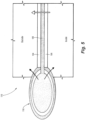
- Fig. 1 a partial view of an embodiment of a system in accordance with the disclosure is shown in Fig. 1 and is designated generally by reference character 100.
- FIGs. 2-6 Other embodiments of systems in accordance with the disclosure, or aspects thereof, are provided in Figs. 2-6 , as will be described.
- the systems and methods described herein can be used to control thermal conductivity or thermal resistivity in wall panels, such as for regulating temperatures in spacecraft, aircraft, or high-speed vehicle or capsule or the like.
- the system includes a wall panel 102, e.g. for the exterior wall of a spacecraft, aircraft, or the like.
- the wall panel 102 includes an exterior wall 104 and an interior wall 106 that is separated from the exterior wall 104 by a variable insulation gap 108 occupied by an insulation medium such as a liquid, a gas, or a vacuum which for purposes of this disclosure includes a gas-evacuated volume which can include trace amounts of gas effectively behaving like a vacuum.
- a flow driver 110 is connected in fluid communication with the insulation medium in the gap 108.
- the flow driver 110 is configured to selectively switch properties of the insulation medium in the variable insulation gap 108 between a conduction mode and in an insulation mode.
- the insulation medium has a first effective thermal conductivity in the insulation mode, and a second effective thermal conductivity in the conduction mode.
- the first effective thermal conductively is lower than the second effective thermal conductivity.
- the gap 108 has a substantially constant width W spatially, and is also substantially constant over time regardless of whether the flow driver 110 is in the insulation mode or in the conduction mode.
- the substantially constant width W, the insulation medium in the gap 108, the exterior wall 104, and the interior wall 106 are all configured so that in the insulation mode, the gap 108 is too narrow for natural convection currents to form turbulent flows in the gap 108.
- the gap width W can be maintained by standoffs in the gap 108, such as the pins 114 shown in Fig. 2 , the straight fins 116 shown in Fig. 3 , the wavy fins 118 shown in Fig. 4 , or any other suitable type of standoffs that allow for the change in fluid needed to switch between the insulation mode and the conduction mode.
- the small insulating standoffs 114, 116, 118 do not conduct heat easily, but they do allow for flow through the gap 108.
- the flow driver 110 can be a fan, a blower, an agitator, a fluid chamber with thermally adaptive geometry/volume, or a pump.
- the outlet of the flow driver 110 is connected to a first end of the gap 108, and a return conduit 112 connects to the opposite end of the gap to return fluid to the flow driver 110.
- the flow driver 110 is configured to stop fluid flow through the variable insulation gap 108 in the insulation mode to inhibit convection across the variable insulation gap 108.
- the flow driver 110 is configured to drive fluid through the gap 108 in the conduction mode to cause convective heat transfer across the variable insulation gap 108 for heat exchange between the exterior and interior walls 104, 106 by forced convection.
- the insulation medium is of a single phase in both the insulation mode and in the conduction mode, i.e. the insulation medium does not change phase.
- the flow driver 110 switches between the insulation mode and the conduction mode by changing properties of the fluid medium in the gap 108, and in the case show in Fig. 1 , the property switched is convection coefficient, by switching between forced convection in the conduction state and natural convection in the insulation state. As described above, in the insulation state, there is little or no convective heat transfer across the gap 109.
- the flow driver 110 is configured to switch repeatedly back and forth between the conduction and insulation modes as often as needed, e.g. by stopping flow and starting flow through the gap 108 as needed to regulate temperatures on the inside of the wall panel 102.
- the insulation medium in the gap 108 can have a convective heat transfer coefficient h between 2.5-25 W/(m 2 K), inclusive of endpoints, in the insulation mode, and a heat transfer coefficient h between 10-500 W/(m 2 K), inclusive of endpoints, in the conduction mode, wherein h is higher in the conduction mode than in the insulation mode.
- the heat transfer coefficient h in the conduction mode can be at least 5 times greater than in the insulation mode.
- the flow driver 110 is configured to change pressure and/or density of the insulation medium in the gap 108 in switching between the insulation mode and the conduction mode.
- the insulation medium in the insulation mode the insulation medium is a vacuum, inclusive of trace amounts of gas.
- the insulation medium in the conduction mode, the insulation medium can be a pressurized gas.
- the flow driver 110 changes between the insulation and conduction modes by evacuating or filling the gap 108 with the gas medium.
- the density of the gas is altered between dense and less dense, based on the state of a bimetallic tank as the flow driver 110. As the temperature of the bimetallic element changes, the geometry and/or volume of the bimetallic element change, causing a rise or fall in the gas pressure inside the gap 108.
- the insulation medium is a first fluid in the insulation mode, and is a second fluid in the conduction mode, wherein the flow driver is configured to swap the first fluid with the second fluid and vice versa to switch between the conduction and insulation modes.
- the first fluid is chemically different from the second fluid, e.g. air for the insulation mode and water or oil for the conduction mode.
- the interior wall 106 includes a first surface 120 facing inward toward the variable insulation gap 108.
- the exterior wall 104 includes a second surface 122 facing inward toward the variable insulation gap 108.
- Each of the first and second surfaces 120, 122 includes a reflectively sufficient to ensure convection is dominant over thermal radiation as a heat transfer mode across the variable insulation gap 108.
- heat exchange can be into the interior space, or out of the interior space as indicated by the two long heat transfer arrows in Fig. 1 .
- the conduction mode will allow for this.
- the conduction mode can allow this.
- the insulation mode can be used as a heat shield to help keep the interior of the spacecraft from heating up even more.
- the insulation mode can be used to preserve heat in the interior of the spacecraft.
- a scpacecraft 124 is shown schematically, with a plurality of wall panels 102 as described above enclosing the interior 126 of the spacecraft.
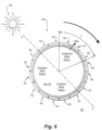
- a method of operating a system as described above includes allowing the exterior and internal walls 104, 106 (labeled in Fig. 1 ) in each wall 102 of a spacecraft 124 to rotate as the spacecraft rotates in a vacuum environment, as indicated by the rotation arrow in Fig. 6 .
- a source 128 of radiative heat such as the sun or a planetary body such as the moon or Venus, is located on one side of the spacecraft 124.
- a side of the spacecraft 124 diametrically opposite along the axis A from the source 128 of heat is exposed to a background radiation 130 so that each thermally adaptive wall 102 of the spacecraft 124 is cyclically exposed to the source 128 of radiative heat alternating with the background radiation 130.
- the method includes switching from the conduction mode to the insulation mode for portions of a rotation of the spacecraft between where a given one of the thermally adaptive walls 102 faces the source 128 of radiative heat and where the thermally adaptive wall 102 faces the background radiation opposite the source of radiative heat, and switching to the conduction mode for other portions P of the rotation.
- Heat exchange in the portions P of the rotation can either be heat flowing into the interior 126, or heat flowing out of the interior 126 as needed, and as indicated by the heat transfer arrows in the portion P of the rotation in Fig. 6 .
- This method can be implemented by a controller 132, e.g. as machine readable instructions on the controller 132, connected to control the flow driver 110 of Fig. 1 .
- the controller 132 can use sensors 134 for feedback control based on the temperatures of the walls 104, 106.
- the environment outside of the device varies greatly depending on the condition it is in, and inside of the device or compartment there is a need to keep the temperature range controlled. In some instances, it is advantageous to insulate, while others allows heat transfer.
- Systems and methods as disclosed herein allows for broader thermal envelopes, which can increase capability, performance, or efficiency of components.
- the rate of convection does not need to be constant over the entire device. This can be useful to heat/cool certain regions more than others.
- the systems and methods disclosed herein can be made low in weight and high in reliability, and can be used as smart thermal insulation. High levels of variability of thermal conduction are possible with systems and methods disclosed herein, up to 200 times or more between the conduction mode versus the insulation mode.
- Systems and methods as disclosed herein can be applied to heat exchanger with automated heat flux or stream outlet temperature. Such exchangers can be employed in fuel or oil heating to prevent coking, water heating to prevent overheating.
Landscapes
- Engineering & Computer Science (AREA)
- General Engineering & Computer Science (AREA)
- Mechanical Engineering (AREA)
- General Health & Medical Sciences (AREA)
- Aviation & Aerospace Engineering (AREA)
- Health & Medical Sciences (AREA)
- Remote Sensing (AREA)
- Biodiversity & Conservation Biology (AREA)
- Life Sciences & Earth Sciences (AREA)
- Environmental & Geological Engineering (AREA)
- Environmental Sciences (AREA)
- Toxicology (AREA)
- Emergency Medicine (AREA)
- Critical Care (AREA)
- Thermal Sciences (AREA)
- Physics & Mathematics (AREA)
- Thermal Insulation (AREA)
Abstract
Description
- The present disclosure relates to thermal insulation, and more particularly to active insulation such as for use on spacecraft, aircraft, and the like.
- Thermal stabilization of the interior in various application such as satellites, space modules and high-velocity vehicles may be very challenging. For instance, satellite surface temperature on the sunny side may be +150°C and -100°C on the opposite side. For a space module rotating around the planet, this may cause undesired issues with the ECS (environment control system) and various other challenges.
- The conventional techniques have been considered satisfactory for their intended purpose. However, there is an ever present need for improved systems and methods for thermal management and insulation such as for use in maintaining interior temperatures onboard spacecraft, aircraft, and the like. This disclosure provides a solution for this need.
- A system includes a wall panel including an exterior wall. An interior wall is separated from the exterior wall by a variable insulation gap occupied by an insulation medium. A flow driver is connected in fluid communication with the insulation medium. The flow driver is configured to selectively switch properties of the insulation medium in the variable insulation gap between a conduction mode and in an insulation mode. The insulation medium has a first effective thermal conductivity in the insulation mode, and a second effective thermal conductivity in the conduction mode. The first effective thermal conductively is lower than the second effective thermal conductivity.
- The gap can have a substantially constant width spatially, and the substantially constant width can also be substantially constant over time regardless of whether the flow driver is in the insulation mode or in the conduction mode. The substantially constant width, the insulation medium, the exterior wall, and the interior wall can be configured so that in the insulation mode, the gap is too narrow for natural convection currents to form turbulent flows in the gap.
- The driver can be configured to stop fluid flow through the variable insulation gap in the insulation mode to inhibit convection across the variable insulation gap, and to drive fluid through the gap in the conduction mode to cause convective heat transfer across the variable insulation gap by forced convection. The flow driver can include at least one of a fan, a blower, an agitator, a fluid chamber with thermally adaptive geometry/volume, or a pump.
- The insulation medium can have a convective heat transfer coefficient h between 2.5-25 W/(m2K), inclusive of endpoints, in the insulation mode, and a heat transfer coefficient h between 10-500 W/(m2K), inclusive of endpoints, in the conduction mode, wherein h is higher in the conduction mode than in the insulation mode. The heat transfer coefficient in the conduction mode can be at least 5 times greater than in the insulation mode. The insulation medium can be of a single phase in both the insulation mode and in the conduction mode.
- The insulation medium can be a gas. The driver is configured to change pressure and/or density of the insulation medium in switching between the insulation mode and the conduction mode. In the insulation mode the insulation medium can be a vacuum, and wherein in the conduction mode, the insulation medium is a gas. The insulation medium can be a first fluid in the insulation mode, and can be a second fluid in the conduction mode, wherein the flow driver can be configured to swap the first fluid with the second fluid and vice versa to switch between the conduction and insulation modes. The first fluid can be chemically different from the second fluid.
- The interior wall can include a first surface facing inward toward the variable insulation gap. The exterior wall can include a second surface facing inward toward the variable insulation gap. Each of the first and second surfaces can include a reflectively sufficient to ensure convection is dominant over thermal radiation as a heat transfer mode across the variable insulation gap. Standoffs can be included in the variable insulation gap.
- A method of operating a system as described above includes rotating the exterior and internal wall panels as a wall of a spacecraft as the spacecraft rotates in a vacuum environment. A source of radiative heat is located on one side of the spacecraft, and a side of the spacecraft opposite from the source of heat is exposed to a background radiation so that the wall of the spacecraft is cyclically exposed to the source of radiative heat alternating with the background radiation. They method includes switching from the conduction mode to the insulation mode for portions of a rotation of the spacecraft between where the wall faces the source of radiative heat and where the wall faces the background radiation opposite the source of radiative heat, and switching to the conduction mode for other portions of the rotation.
- These and other features of the systems and methods of the subject disclosure will become more readily apparent to those skilled in the art from the following detailed description of the preferred embodiments taken in conjunction with the drawings.
- So that those skilled in the art to which the subject disclosure appertains will readily understand how to make and use the devices and methods of the subject disclosure without undue experimentation, preferred embodiments thereof will be described in detail herein below with reference to certain figures, wherein:
-
Fig. 1 is a schematic cross-sectional plan view of an embodiment of a system constructed in accordance with the present disclosure, showing the wall panel with spaced apart walls separated by the variable insulation gap; -
Figs. 2-4 are schematic perspective views of wall panels as shown inFig. 1 with three different kinds of spacers for maintaining the width of the variable insulation gap, pins, fins, and wavy fins, respectively; -
Fig. 5 is a schematic cross-sectional plan view of an embodiment of the system ofFig. 1 , showing a bimetallic mechanism as the driver for variable insulation switching; and -
Fig. 6 is a schematic view of the system ofFig. 1 , showing a rotating spacecraft with at least one of the wall panels ofFig. 1 , and showing a method of switching the wall panel between conduction and insulation modes as the spacecraft rotates to regulate temperatures inside the spacecraft. - Reference will now be made to the drawings wherein like reference numerals identify similar structural features or aspects of the subject disclosure. For purposes of explanation and illustration, and not limitation, a partial view of an embodiment of a system in accordance with the disclosure is shown in
Fig. 1 and is designated generally byreference character 100. Other embodiments of systems in accordance with the disclosure, or aspects thereof, are provided inFigs. 2-6 , as will be described. The systems and methods described herein can be used to control thermal conductivity or thermal resistivity in wall panels, such as for regulating temperatures in spacecraft, aircraft, or high-speed vehicle or capsule or the like. - The system includes a
wall panel 102, e.g. for the exterior wall of a spacecraft, aircraft, or the like. Thewall panel 102 includes anexterior wall 104 and aninterior wall 106 that is separated from theexterior wall 104 by avariable insulation gap 108 occupied by an insulation medium such as a liquid, a gas, or a vacuum which for purposes of this disclosure includes a gas-evacuated volume which can include trace amounts of gas effectively behaving like a vacuum. Aflow driver 110 is connected in fluid communication with the insulation medium in thegap 108. Theflow driver 110 is configured to selectively switch properties of the insulation medium in thevariable insulation gap 108 between a conduction mode and in an insulation mode. The insulation medium has a first effective thermal conductivity in the insulation mode, and a second effective thermal conductivity in the conduction mode. The first effective thermal conductively is lower than the second effective thermal conductivity. - The
gap 108 has a substantially constant width W spatially, and is also substantially constant over time regardless of whether theflow driver 110 is in the insulation mode or in the conduction mode. The substantially constant width W, the insulation medium in thegap 108, theexterior wall 104, and theinterior wall 106 are all configured so that in the insulation mode, thegap 108 is too narrow for natural convection currents to form turbulent flows in thegap 108. The gap width W can be maintained by standoffs in thegap 108, such as thepins 114 shown inFig. 2 , thestraight fins 116 shown inFig. 3 , thewavy fins 118 shown inFig. 4 , or any other suitable type of standoffs that allow for the change in fluid needed to switch between the insulation mode and the conduction mode. The smallinsulating standoffs gap 108. - With reference again to
Fig. 1 , theflow driver 110 can be a fan, a blower, an agitator, a fluid chamber with thermally adaptive geometry/volume, or a pump. The outlet of theflow driver 110 is connected to a first end of thegap 108, and areturn conduit 112 connects to the opposite end of the gap to return fluid to theflow driver 110. Theflow driver 110 is configured to stop fluid flow through thevariable insulation gap 108 in the insulation mode to inhibit convection across thevariable insulation gap 108. Theflow driver 110 is configured to drive fluid through thegap 108 in the conduction mode to cause convective heat transfer across thevariable insulation gap 108 for heat exchange between the exterior andinterior walls - In a more general sense, the
flow driver 110 switches between the insulation mode and the conduction mode by changing properties of the fluid medium in thegap 108, and in the case show inFig. 1 , the property switched is convection coefficient, by switching between forced convection in the conduction state and natural convection in the insulation state. As described above, in the insulation state, there is little or no convective heat transfer across the gap 109. Theflow driver 110 is configured to switch repeatedly back and forth between the conduction and insulation modes as often as needed, e.g. by stopping flow and starting flow through thegap 108 as needed to regulate temperatures on the inside of thewall panel 102. - The insulation medium in the
gap 108 can have a convective heat transfer coefficient h between 2.5-25 W/(m2K), inclusive of endpoints, in the insulation mode, and a heat transfer coefficient h between 10-500 W/(m2K), inclusive of endpoints, in the conduction mode, wherein h is higher in the conduction mode than in the insulation mode. The heat transfer coefficient h in the conduction mode can be at least 5 times greater than in the insulation mode. - The
flow driver 110 is configured to change pressure and/or density of the insulation medium in thegap 108 in switching between the insulation mode and the conduction mode. In one configuration, in the insulation mode the insulation medium is a vacuum, inclusive of trace amounts of gas. In the conduction mode, the insulation medium can be a pressurized gas. In this configuration, theflow driver 110 changes between the insulation and conduction modes by evacuating or filling thegap 108 with the gas medium. In the configuration shown inFig. 5 , the density of the gas is altered between dense and less dense, based on the state of a bimetallic tank as theflow driver 110. As the temperature of the bimetallic element changes, the geometry and/or volume of the bimetallic element change, causing a rise or fall in the gas pressure inside thegap 108. Changing the state back and forth of the bimetallic tank switches between the insulation mode and the conduction mode. Although described above with a constant gap width W, it is also contemplated that a configuration can be made wherein theflow driver 110 inflates thegap 108 to expand its width W or contract its width W to adjust the effective thermal conductivity or thermal resistance across thegap 108. - In another configuration, the insulation medium is a first fluid in the insulation mode, and is a second fluid in the conduction mode, wherein the flow driver is configured to swap the first fluid with the second fluid and vice versa to switch between the conduction and insulation modes. The first fluid is chemically different from the second fluid, e.g. air for the insulation mode and water or oil for the conduction mode.
- With continued reference to
Fig. 1 , theinterior wall 106 includes afirst surface 120 facing inward toward thevariable insulation gap 108. Theexterior wall 104 includes asecond surface 122 facing inward toward thevariable insulation gap 108. Each of the first andsecond surfaces variable insulation gap 108. - During the conduction mode, heat exchange can be into the interior space, or out of the interior space as indicated by the two long heat transfer arrows in
Fig. 1 . For example, if a spacecraft needs to expel heat to the outside, the conduction mode will allow for this. Similarly, if the interior of a spacecraft needs to receive heat from the outside, the conduction mode can allow this. When the interior of the spacecraft needs to expel heat but theoutside wall 104 is at higher temperatures than the interior of the space craft, the insulation mode can be used as a heat shield to help keep the interior of the spacecraft from heating up even more. Similarly, if the interior of the spacecraft is at or near a cold limit, and theoutside wall 104 is colder than the interior of the spacecraft, the insulation mode can be used to preserve heat in the interior of the spacecraft. - With reference now to
Fig. 6 , a scpacecraft 124 is shown schematically, with a plurality ofwall panels 102 as described above enclosing the interior 126 of the spacecraft. A method of operating a system as described above includes allowing the exterior andinternal walls 104, 106 (labeled inFig. 1 ) in eachwall 102 of a spacecraft 124 to rotate as the spacecraft rotates in a vacuum environment, as indicated by the rotation arrow inFig. 6 . Asource 128 of radiative heat such as the sun or a planetary body such as the moon or Venus, is located on one side of the spacecraft 124. A side of the spacecraft 124 diametrically opposite along the axis A from thesource 128 of heat is exposed to abackground radiation 130 so that each thermallyadaptive wall 102 of the spacecraft 124 is cyclically exposed to thesource 128 of radiative heat alternating with thebackground radiation 130. The method includes switching from the conduction mode to the insulation mode for portions of a rotation of the spacecraft between where a given one of the thermallyadaptive walls 102 faces thesource 128 of radiative heat and where the thermallyadaptive wall 102 faces the background radiation opposite the source of radiative heat, and switching to the conduction mode for other portions P of the rotation. Heat exchange in the portions P of the rotation can either be heat flowing into the interior 126, or heat flowing out of the interior 126 as needed, and as indicated by the heat transfer arrows in the portion P of the rotation inFig. 6 . This method can be implemented by acontroller 132, e.g. as machine readable instructions on thecontroller 132, connected to control theflow driver 110 ofFig. 1 . Thecontroller 132 can usesensors 134 for feedback control based on the temperatures of thewalls - It is desirable to have systems and methods as disclosed herein that allows heat exchange at some conditions, while being thermally insulating at other conditions. Applications of systems and method as disclosed herein include spacesuits, space modules, or satellites where temperature ranges can be extreme. The skin of an aircraft can benefit since the outside environment can be very cold at altitude conditions to very hot at hypersonic conditions or on a hot day. An environmental control system (ECS) which is mounted within a compartment on an aircraft can benefit. A layer within a heat exchanger to prevent overheating or freezing of fluids can benefit. A compartment on an aircraft such as an electronics bay adjacent to the outside of the plane can benefit.
- In all of these examples, the environment outside of the device varies greatly depending on the condition it is in, and inside of the device or compartment there is a need to keep the temperature range controlled. In some instances, it is advantageous to insulate, while others allows heat transfer.
- Systems and methods as disclosed herein allows for broader thermal envelopes, which can increase capability, performance, or efficiency of components. The rate of convection does not need to be constant over the entire device. This can be useful to heat/cool certain regions more than others. The systems and methods disclosed herein can be made low in weight and high in reliability, and can be used as smart thermal insulation. High levels of variability of thermal conduction are possible with systems and methods disclosed herein, up to 200 times or more between the conduction mode versus the insulation mode. Systems and methods as disclosed herein can be applied to heat exchanger with automated heat flux or stream outlet temperature. Such exchangers can be employed in fuel or oil heating to prevent coking, water heating to prevent overheating.
- The methods and systems of the present disclosure, as described above and shown in the drawings, provide for controlling thermal conductivity or thermal resistivity in wall panels, such as for regulating temperatures in spacecraft, aircraft, or high-speed vehicle or capsule or the like. While the apparatus and methods of the subject disclosure have been shown and described with reference to preferred embodiments, those skilled in the art will readily appreciate that changes and/or modifications may be made thereto without departing from the scope of the invention as defined by the claims.
Claims (15)
- A system comprising:a wall panel (102) including an exterior wall (104);an interior wall (106) separated from the exterior wall by a variable insulation gap (108) occupied by an insulation medium; anda flow driver (110) connected in fluid communication with the insulation medium, wherein the flow driver is configured to selectively switch properties of the insulation medium in the variable insulation gap between a conduction mode and in an insulation mode, wherein insulation medium has a first effective thermal conductivity in the insulation mode, and a second effective thermal conductivity in the conduction mode, wherein the first effective thermal conductively is lower than the second effective thermal conductivity.
- The system as recited in claim 1, wherein the gap has a substantially constant width spatially, and wherein the substantially constant width is also substantially constant over time regardless of whether the flow driver is in the insulation mode or in the conduction mode.
- The system as recited in claim 2, wherein the substantially constant width, the insulation medium, the exterior wall, and the interior wall are configured so that in the insulation mode, the gap is too narrow for natural convection currents to form turbulent flows in the gap.
- The system as recited in claim 3, wherein the driver is configured to stop fluid flow through the variable insulation gap in the insulation mode to inhibit convection across the variable insulation gap, and to drive fluid through the gap in the conduction mode to cause convective heat transfer across the variable insulation gap by forced convection.
- The system as recited in claim 4, wherein the insulation medium has a convective heat transfer coefficient h between 2.5-25 W/(m2K), inclusive of endpoints, in the insulation mode, and a heat transfer coefficient h between 10-500 W/(m2K), inclusive of endpoints, in the conduction mode, wherein h is higher in the conduction mode than in the insulation mode.
- The system as recited in claim 5, wherein the heat transfer coefficient in the conduction mode is at least 5 times greater than in the insulation mode.
- The system as recited in any preceding claim, wherein the insulation medium is a gas, wherein the driver is configured to change pressure and/or density of the insulation medium in switching between the insulation mode and the conduction mode.
- The system as recited in claim 7, wherein in the insulation mode the insulation medium is a vacuum, and wherein in the conduction mode, the insulation medium is a gas.
- The system as recited in any of claims 1 to 6, wherein the insulation medium is a first fluid in the insulation mode, and is a second fluid in the conduction mode, wherein the flow driver is configured to swap the first fluid with the second fluid and vice versa to switch between the conduction and insulation modes.
- The system as recited in claim 9, wherein the first fluid is chemically different from the second fluid.
- The system as recited in any of claims 1 to 8, wherein the insulation medium is of a single phase in both the insulation mode and in the conduction mode.
- The system as recited in any preceding claim, wherein the interior wall includes a first surface (120) facing inward toward the variable insulation gap, wherein the exterior wall includes a second surface (122) facing inward toward the variable insulation gap, wherein each of the first and second surfaces includes a reflectively sufficient to ensure convection is dominant over thermal radiation as a heat transfer mode across the variable insulation gap.
- The system as recited in any preceding claim, wherein the flow driver (110) includes at least one of a fan, a blower, an agitator, a fluid chamber with thermally adaptive geometry/volume, or a pump.
- The system as recited in any preceding claim, wherein standoffs (114, 116, 118) are included in the variable insulation gap.
- A method of operating a system as recited in any preceding claim, comprising:rotating the exterior and internal walls (104, 106) as a wall of a spacecraft (124) as the spacecraft rotates in a vacuum environment, wherein a source of radiative heat (128) is located on one side of the spacecraft, and a side of the spacecraft opposite from the source of heat is exposed to a background radiation so that the wall of the spacecraft is cyclically exposed to the source of radiative heat alternating with the background radiation; andswitching from the conduction mode to the insulation mode for portions of a rotation of the spacecraft between where the wall faces the source of radiative heat and where the wall faces the background radiation opposite the source of radiative heat, and switching to the conduction mode for other portions of the rotation.
Applications Claiming Priority (1)
| Application Number | Priority Date | Filing Date | Title |
|---|---|---|---|
| US18/111,092 US12644558B2 (en) | 2023-02-17 | 2023-02-17 | Variable thermal insulation |
Publications (1)
| Publication Number | Publication Date |
|---|---|
| EP4417525A1 true EP4417525A1 (en) | 2024-08-21 |
Family
ID=89983322
Family Applications (1)
| Application Number | Title | Priority Date | Filing Date |
|---|---|---|---|
| EP24158086.9A Pending EP4417525A1 (en) | 2023-02-17 | 2024-02-16 | Variable thermal insulation |
Country Status (2)
| Country | Link |
|---|---|
| US (1) | US12644558B2 (en) |
| EP (1) | EP4417525A1 (en) |
Citations (7)
| Publication number | Priority date | Publication date | Assignee | Title |
|---|---|---|---|---|
| US3270802A (en) * | 1963-01-10 | 1966-09-06 | Jay G Lindberg | Method and apparatus for varying thermal conductivity |
| US3450196A (en) * | 1967-08-30 | 1969-06-17 | Trw Inc | Gas pressure control for varying thermal conductivity |
| DE3017252A1 (en) * | 1980-05-06 | 1981-11-12 | Messerschmitt-Bölkow-Blohm GmbH, 8000 München | Internal temp. control of spacecraft - uses sealed liq. panel that changes thickness to control heat loss and maintain constant internal temp. |
| US4871012A (en) * | 1986-09-12 | 1989-10-03 | Ford Aerospace Corporation | Variable conductance thermal insulation blanket |
| US5643485A (en) * | 1988-04-15 | 1997-07-01 | Midwest Research Institute | Cooking utensil with improved heat retention |
| US6073888A (en) * | 1998-12-02 | 2000-06-13 | Loral Space & Communications, Ltd. | Sequenced heat rejection for body stabilized geosynchronous satellites |
| FR3063806A1 (en) * | 2017-03-13 | 2018-09-14 | Airbus Defence And Space Sas | THERMAL TRANSFER DEVICE AND SPATIAL DEVICE COMPRISING SUCH A THERMAL TRANSFER DEVICE |
Family Cites Families (11)
| Publication number | Priority date | Publication date | Assignee | Title |
|---|---|---|---|---|
| US3543839A (en) * | 1969-05-14 | 1970-12-01 | Trw Inc | Multi-chamber controllable heat pipe |
| US3814175A (en) * | 1969-06-04 | 1974-06-04 | Laing Nikolaus | Variable insulation means utilizing convection generators |
| US4037751A (en) | 1973-04-18 | 1977-07-26 | Summa Corporation | Insulation system |
| US5813454A (en) * | 1988-04-15 | 1998-09-29 | Varitec Thermal, L.L.C. | Variably insulating portable heater/cooler |
| US4858678A (en) * | 1988-06-02 | 1989-08-22 | The Boeing Company | Variable heat conductance heat exchanger |
| US5670264A (en) | 1994-05-10 | 1997-09-23 | Shertech, Inc. | Thermal barrier |
| US7621239B2 (en) | 2006-06-16 | 2009-11-24 | Rice Allen C | Hot water heater blanket assembly establishing dead air spaces |
| DE102008025389B4 (en) | 2007-12-21 | 2013-02-28 | Airbus Operations Gmbh | A method for insulating an aircraft cabin wall or for cooling or reheating aircraft cabin air and aircraft cabin wall suitable thereto |
| US20130081786A1 (en) * | 2011-06-17 | 2013-04-04 | William W. Clark | Variable thermal insulation |
| DE102015215063A1 (en) * | 2015-08-06 | 2017-02-09 | Mahle International Gmbh | Container for a waste heat recovery cycle |
| KR102154548B1 (en) | 2019-07-03 | 2020-09-11 | 주식회사 일신산업 | Flame-retardant insulating module |
-
2023
- 2023-02-17 US US18/111,092 patent/US12644558B2/en active Active
-
2024
- 2024-02-16 EP EP24158086.9A patent/EP4417525A1/en active Pending
Patent Citations (7)
| Publication number | Priority date | Publication date | Assignee | Title |
|---|---|---|---|---|
| US3270802A (en) * | 1963-01-10 | 1966-09-06 | Jay G Lindberg | Method and apparatus for varying thermal conductivity |
| US3450196A (en) * | 1967-08-30 | 1969-06-17 | Trw Inc | Gas pressure control for varying thermal conductivity |
| DE3017252A1 (en) * | 1980-05-06 | 1981-11-12 | Messerschmitt-Bölkow-Blohm GmbH, 8000 München | Internal temp. control of spacecraft - uses sealed liq. panel that changes thickness to control heat loss and maintain constant internal temp. |
| US4871012A (en) * | 1986-09-12 | 1989-10-03 | Ford Aerospace Corporation | Variable conductance thermal insulation blanket |
| US5643485A (en) * | 1988-04-15 | 1997-07-01 | Midwest Research Institute | Cooking utensil with improved heat retention |
| US6073888A (en) * | 1998-12-02 | 2000-06-13 | Loral Space & Communications, Ltd. | Sequenced heat rejection for body stabilized geosynchronous satellites |
| FR3063806A1 (en) * | 2017-03-13 | 2018-09-14 | Airbus Defence And Space Sas | THERMAL TRANSFER DEVICE AND SPATIAL DEVICE COMPRISING SUCH A THERMAL TRANSFER DEVICE |
Also Published As
| Publication number | Publication date |
|---|---|
| US12644558B2 (en) | 2026-06-02 |
| US20240280209A1 (en) | 2024-08-22 |
Similar Documents
| Publication | Publication Date | Title |
|---|---|---|
| US4162701A (en) | Thermal control canister | |
| US20150068703A1 (en) | Thermal management system and method of assembling the same | |
| EP2412631B1 (en) | Cooling device for high temperature fluid and cooling method for high temperature fluid. | |
| JP6375109B2 (en) | Reusable thermal protection system with high thermal conductivity | |
| US10228197B2 (en) | Variable heat rejection device | |
| EP2644508A1 (en) | System and method for cooling electrical components | |
| WO2010037872A1 (en) | Spaceship heat module | |
| CN101633411A (en) | Actuating mechanism of spacecraft for integrating heat control and liquid momentum wheel | |
| EP2203696A1 (en) | Topping cycle for a sub-ambient cooling system | |
| WO2016099785A1 (en) | Battery pack with variable-conductance heat pipe (vchp) cooling | |
| WO2013130424A1 (en) | Thermoelectric air conditioner | |
| US20140190185A1 (en) | System and method for preventing overheating or excessive backpressure in thermoelectric systems | |
| US20170328654A1 (en) | Variable Heat Rejection Device | |
| US11186387B2 (en) | Variable heat rejection device | |
| EP2317601B1 (en) | An integrated antenna structure with an imbedded cooling channel | |
| US20090031733A1 (en) | Thermotunneling refrigeration system | |
| US20240280209A1 (en) | Variable thermal insulation | |
| JP7205970B2 (en) | Heat transport system and transportation | |
| US9644869B2 (en) | System and method for cooling structures having both an active state and an inactive state | |
| US9714777B1 (en) | Heat pipe and radiator system with thermoelectric cooler | |
| EP3904812A1 (en) | Loop-type heat pipe and transport device | |
| US20250044037A1 (en) | Systems and techniques for dissipating heat | |
| US20090101311A1 (en) | System and Method for Cooling Using Two Separate Coolants | |
| CN121336312A (en) | Battery cooling device, battery cooling system | |
| WO2016098107A2 (en) | System for enhancing solar panel efficiency and methods of using same |
Legal Events
| Date | Code | Title | Description |
|---|---|---|---|
| PUAI | Public reference made under article 153(3) epc to a published international application that has entered the european phase |
Free format text: ORIGINAL CODE: 0009012 |
|
| STAA | Information on the status of an ep patent application or granted ep patent |
Free format text: STATUS: THE APPLICATION HAS BEEN PUBLISHED |
|
| AK | Designated contracting states |
Kind code of ref document: A1 Designated state(s): AL AT BE BG CH CY CZ DE DK EE ES FI FR GB GR HR HU IE IS IT LI LT LU LV MC ME MK MT NL NO PL PT RO RS SE SI SK SM TR |
|
| STAA | Information on the status of an ep patent application or granted ep patent |
Free format text: STATUS: REQUEST FOR EXAMINATION WAS MADE |
|
| 17P | Request for examination filed |
Effective date: 20250219 |
|
| STAA | Information on the status of an ep patent application or granted ep patent |
Free format text: STATUS: EXAMINATION IS IN PROGRESS |
|
| 17Q | First examination report despatched |
Effective date: 20251126 |