EP4417522A1 - Push button motion indicator mechanism - Google Patents
Push button motion indicator mechanism Download PDFInfo
- Publication number
- EP4417522A1 EP4417522A1 EP24157827.7A EP24157827A EP4417522A1 EP 4417522 A1 EP4417522 A1 EP 4417522A1 EP 24157827 A EP24157827 A EP 24157827A EP 4417522 A1 EP4417522 A1 EP 4417522A1
- Authority
- EP
- European Patent Office
- Prior art keywords
- housing
- push button
- plunger
- indicator
- retaining
- Prior art date
- Legal status (The legal status is an assumption and is not a legal conclusion. Google has not performed a legal analysis and makes no representation as to the accuracy of the status listed.)
- Granted
Links
Images



Classifications
-
- B—PERFORMING OPERATIONS; TRANSPORTING
- B64—AIRCRAFT; AVIATION; COSMONAUTICS
- B64D—EQUIPMENT FOR FITTING IN OR TO AIRCRAFT; FLIGHT SUITS; PARACHUTES; ARRANGEMENT OR MOUNTING OF POWER PLANTS OR PROPULSION TRANSMISSIONS IN AIRCRAFT
- B64D45/00—Aircraft indicators or protectors not otherwise provided for
- B64D45/0005—Devices specially adapted to indicate the position of a movable element of the aircraft, e.g. landing gear
-
- B—PERFORMING OPERATIONS; TRANSPORTING
- B64—AIRCRAFT; AVIATION; COSMONAUTICS
- B64C—AEROPLANES; HELICOPTERS
- B64C13/00—Control systems or transmitting systems for actuating flying-control surfaces, lift-increasing flaps, air brakes, or spoilers
- B64C13/24—Transmitting means
- B64C13/26—Transmitting means without power amplification or where power amplification is irrelevant
- B64C13/28—Transmitting means without power amplification or where power amplification is irrelevant mechanical
-
- B—PERFORMING OPERATIONS; TRANSPORTING
- B64—AIRCRAFT; AVIATION; COSMONAUTICS
- B64C—AEROPLANES; HELICOPTERS
- B64C9/00—Adjustable control surfaces or members, e.g. rudders
- B64C9/14—Adjustable control surfaces or members, e.g. rudders forming slots
- B64C9/22—Adjustable control surfaces or members, e.g. rudders forming slots at the front of the wing
- B64C9/24—Adjustable control surfaces or members, e.g. rudders forming slots at the front of the wing by single flap
-
- B—PERFORMING OPERATIONS; TRANSPORTING
- B64—AIRCRAFT; AVIATION; COSMONAUTICS
- B64D—EQUIPMENT FOR FITTING IN OR TO AIRCRAFT; FLIGHT SUITS; PARACHUTES; ARRANGEMENT OR MOUNTING OF POWER PLANTS OR PROPULSION TRANSMISSIONS IN AIRCRAFT
- B64D45/00—Aircraft indicators or protectors not otherwise provided for
- B64D45/0005—Devices specially adapted to indicate the position of a movable element of the aircraft, e.g. landing gear
- B64D2045/001—Devices specially adapted to indicate the position of a movable element of the aircraft, e.g. landing gear for indicating symmetry of flaps deflection
Definitions
- Exemplary embodiments pertain to the art of motion indicator mechanisms, and in particular to jam indicator mechanisms for high lift torque limiters of, for example, aircraft control surface drive mechanisms.
- Control surfaces of aircraft are moved and controlled by rotary gear actuators along with rack and pinion devices operably connected to the control surfaces.
- These rotary gear actuators drive the control surfaces to selected positions indicated by flight control systems or pilot input to the controls, and to maintain the control surfaces at the selected positions.
- a torque limiter connected in-line to the actuator acts to isolate the downstream components and divert the overload to an earth structure while a jam is indicated by a jam indicator.
- the current jam indicator is a lever type mechanism, where a plunger acts on a pivoted indicator arm. The indicator arm is in a first position if there is no jam, and a second position if a jam is indicated.
- the indicator arm In the first position, the indicator arm is retained by a spring clip, while in the second position the indicator arm is released from the spring clip.
- the displacement of the pivoted indicator arm depends on the length of the arm. To be noticeable via visual inspection, a large indicator arm is needed which in turn requires a larger housing to contain the arm. Further, the position of the indicator arm may depend on retention by the spring clip, and failure of the spring clip may result in a false indication of a jam.
- a motion indicator in one embodiment, includes a housing and a plunger extending from a first housing end of the housing and axially movable relative to the housing.
- the plunger is biased into an axially extended position relative to the housing via a plunger biasing element, and the plunger is configured to detect motion of a component adjacent to a plunger tip.
- a push button is located at a second housing end of the housing and is axially moveable relative to the housing. The push button is biased toward an axially extended position relative to the housing via a biasing element.
- a retaining assembly is configured to retain the push button in an axially retracted position relative to the housing. The retaining assembly is configured to release the push button and allow the button biasing element to urge the push button toward the axially extended position when the plunger is urged toward a retracted position via motion of the component adjacent to the plunger tip.
- the housing includes an outer sleeve and an inner sleeve positioned radially inboard of the outer sleeve.
- the push button is located radially between the outer sleeve and the inner sleeve, and the inner sleeve is located radially between the plunger and the push button.
- the retaining assembly includes one or more retaining balls positioned in a ball opening in the inner sleeve, and one or more retaining elements extending radially inwardly from the push button body to interact with the one or more retaining balls and retain the push button in the retracted position.
- the one or more retaining balls are configured to move radially inwardly when the plunger is urged toward the retracted position, thus releasing the push button.
- the one or more retaining elements includes one or more disc springs.
- the one or more retaining elements includes one or more tine springs.
- the spring element is axially retained between a housing wall and a flange of the push button.
- a method of indicating motion of a component includes locating a plunger of a motion indicator adjacent the component.
- the plunger is located in a housing and extends from a first housing end of the housing and is axially movable relative to the housing.
- the plunger is biased into an axially extended position relative to the housing via a plunger biasing element.
- the plunger is urged toward a retracted position via motion of the component toward the plunger.
- a retainer of a push button positioned in the housing is released via movement of the plunger toward the retracted position.
- the push button is located at a second housing end of the housing and is axially moveable relative to the housing.
- the push button is biased toward an axially extended position relative to the housing via a biasing element.
- the push button is urged toward the axially extended position via the biasing element thereby indicating motion of the component.
- the housing includes an outer sleeve and an inner sleeve located radially inboard of the outer sleeve.
- the push button is positioned radially between the outer sleeve and the inner sleeve, and the inner sleeve is located radially between the plunger and the push button.
- the retaining assembly includes one or more retaining balls located in a ball opening in the inner sleeve.
- the push button is retained in the retracted position via interaction between one or more retaining elements extending radially inwardly from the housing and the one or more retaining balls.
- the one or more retaining balls are moved radially inwardly when the plunger is urged toward the retracted position, thus releasing the push button.
- the one or more retaining elements includes one or more disc springs.
- the one or more retaining elements includes one or more tine springs.
- the spring element is axially retained between a housing wall and a flange of the push button.
- a control surface actuation system in yet another embodiment, includes an actuator operably connected to a control surface, and a jam detecting apparatus of the actuator including an actuator sleeve configured to move axially along an actuator housing when the actuator is subjected to one of an overtorque or jam condition.
- a jam indicator is in operable communication with the actuator sleeve.
- the jam indicator includes an indicator housing, and a plunger extending from a first housing end of the indicator housing and axially movable relative to the indicator housing. The plunger is biased into an axially extended position relative to the indicator housing via a plunger biasing element, and the plunger is configured to detect motion of a component adjacent to a plunger tip.
- a push button is located at a second housing end of the indicator housing and is axially moveable relative to the indicator housing.
- the push button is biased toward an axially extended position relative to the indicator housing via a button biasing element.
- a retaining assembly is configured to retain the push button in an axially retracted position relative to the indicator housing.
- the retaining assembly is configured to release the push button and allow the button biasing element to urge the push button toward the axially extended position when the plunger is urged toward a retracted position via motion of the component adjacent to the plunger tip, thereby indicating that the actuator has been subjected to one of an overtorque or jam condition.
- the indicator housing includes an outer sleeve and an inner sleeve located radially inboard of the outer sleeve.
- the push button is located radially between the outer sleeve and the inner sleeve.
- the inner sleeve is located radially between the plunger and the push button.
- the retaining assembly includes one or more retaining balls located in a ball opening in the inner sleeve, and one or more retaining elements extending radially inwardly from the indicator housing to interact with the one or more retaining balls and retain the push button in the retracted position.
- the one or more retaining balls are configured to move radially inwardly when the plunger is urged toward the retracted position, thus releasing the push button.
- the one or more retaining elements includes one or more disc springs or one or more tine springs.
- the button spring element is axially retained between an indicator housing wall and a flange of the push button.
- FIG. 1 shown is a schematic illustration of an embodiment of a control surface actuation system 10 for, for example, an aircraft.
- the system 10 includes a control surface 12, for example, a slat, a flap or a vane, operably connected to a rotary actuator 14, for example, a mechanical, electro-mechanical, hydraulic or electro-hydraulic actuator.
- the control surface 12 is operably connected to the actuator 14 via a rack 16 and pinion 18 arrangement. Operation of the actuator 14 rotates the pinion 18 about a pinion axis 20, moving the rack relative to the pinion 18, and thus moving the control surface 12.
- rack 16 and pinion 18 arrangement is illustrated and described herein, other arrangements may be utilized to operably connect the actuator 14 to the control surface 12.
- a torque limiter within the actuator acts to isolate the downstream components and divert the overload to an earth structure while a jam is indicated by a jam indicator mechanism 34 which may indicate potential damage to the system 10.
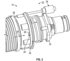
- the torque limiter within the actuator 14 includes balls 24 positioned in detents 26 in the output shaft 28 of the actuator 14. When the actuator 14 is subjected to an overtorque or jam condition, the balls 24 climb the detents 26 along an actuator axial direction 30, and pushes a sleeve 32 along the same actuator axial direction 30. Movement of this sleeve 32 in turn triggers activation of a jam indicator 34 fixed to the actuator housing 33.
- the jam indicator 34 includes an indicator housing 36 fixed relative to the actuator housing 28.
- the indicator housing 36 includes an indicator thread 38 receivable into a complimentary actuator thread 40 in the actuator housing 28 to secure the indicator housing 36 at the actuator housing 28.
- a push button 42 is located inside the indicator housing 36 and the position of the push button 42 relative to indicator housing 36 is a visual indication of whether or not the actuator 14 has been subjected to an overtorque or jam condition.
- the jam indicator 34 indicates that the actuator 14 has not been subjected to an overtorque or jam condition.
- the jam indicator 34 indicates that the actuator 14 has been subjected to an overtorque or jam condition.
- the jam indicator 34 further includes a plunger 56 positioned radially inside of the inner sleeve 54.
- the plunger 56 extends through a housing opening 58 axially toward the sleeve 32 and is interactive therewith as will be described further below.
- the plunger 56 is biased toward an extended position, as illustrated in FIG. 3 , by a biasing element, such as a plunger spring 60 located axially between a plunger flange 62 and a housing end 64.
- the plunger 56 includes a plunger body 66 that extends axially inside the inner sleeve 54 toward the push button 42.
- the push button 42 is retained in the retracted position by one or more retaining balls 68 located in a ball opening 70 in the inner sleeve 54.
- the plunger body 66 urges the retaining balls 68 radially outwardly in the ball opening 70. In this position, the retaining balls 68 interfere with a retaining feature of the push button 42.
- the retaining feature is a retaining flange 72 extending radially inwardly. As will be described further, in other embodiments other retaining features may be utilized. Referring now to FIG.
- the sleeve 32 of the torque limiter pushes a plunger tip 74 of the plunger 56, the plunger 56 overcomes the biasing force of the plunger spring 60 and moves axially toward a retracted position.
- the axial movement of the plunger 56 allows the retaining balls 68 to move radially inwardly into a plunger pocket 76 in the plunger body 66. As such, the retaining balls 68 move out of contact with the retaining flange 72 allowing the push button 42 to move axially toward the extended position.
- the push button flange 46 contacts the housing end 78 of the indicator housing 36, thus stopping axial travel of the push button 42.
- the sleeve 32 of the actuator 14 moves away from the plunger tip 74 and the plunger spring 60 again urges the plunger 56 towards the extended position, thus urging the retaining balls 68 radially outwardly in the ball openings 70.
- the specific shape, thickness, material and other properties of the disc springs 80 may be varied to achieve the desired flexibility for ease of reset of the pushbutton 42, while providing a required retention force to retain the push button 42 in the retracted position to prevent inadvertent deployment of the push button 42.
- FIG. 9 and 10 Another embodiment is illustrated in FIG. 9 and 10 , in which the retention feature is a tine spring 82 formed in the pushbutton 42.
- the tine spring 82 includes a plurality of axially extending tine elements 84, with each tine element 84 including a tine barb 86 extending radially inwardly.
- the tine elements 84 are sufficiently flexible to allow the tine elements 84 to move around and past the retaining balls 68, where the tine barbs 86 retain the push button 42 in the retracted position.
- the specific shape, thickness, material and other properties of the tine elements 84 and the tine barbs 86 may be varied to achieve the desired flexibility for ease of reset of the pushbutton 42, while providing a required retention force to retain the push button 42 in the retracted position to prevent inadvertent deployment of the push button 42.
- the jam indicator 34 configurations disclosed herein provide a compact solution that reduces volume and weight of the mechanism, relative to prior art solutions. It is scalable, allowing for use wherever a small movement can be mechanically sensed and mechanically amplified and indicated through a compact push button. Further, the moving parts are contained in a housing, thus not exposed to harsh operating environments.
Landscapes
- Engineering & Computer Science (AREA)
- Aviation & Aerospace Engineering (AREA)
- Mechanical Engineering (AREA)
- Automation & Control Theory (AREA)
- Mechanical Control Devices (AREA)
- Push-Button Switches (AREA)
Abstract
Description
- This application claims the benefit of
India Provisional Application No. 202311010117 filed February 15, 2023 - Exemplary embodiments pertain to the art of motion indicator mechanisms, and in particular to jam indicator mechanisms for high lift torque limiters of, for example, aircraft control surface drive mechanisms.
- Control surfaces of aircraft, such as flaps or slats, are moved and controlled by rotary gear actuators along with rack and pinion devices operably connected to the control surfaces. These rotary gear actuators drive the control surfaces to selected positions indicated by flight control systems or pilot input to the controls, and to maintain the control surfaces at the selected positions. When the actuator exceeds a torque threshold during operation, a torque limiter connected in-line to the actuator acts to isolate the downstream components and divert the overload to an earth structure while a jam is indicated by a jam indicator. The current jam indicator is a lever type mechanism, where a plunger acts on a pivoted indicator arm. The indicator arm is in a first position if there is no jam, and a second position if a jam is indicated. In the first position, the indicator arm is retained by a spring clip, while in the second position the indicator arm is released from the spring clip. The displacement of the pivoted indicator arm depends on the length of the arm. To be noticeable via visual inspection, a large indicator arm is needed which in turn requires a larger housing to contain the arm. Further, the position of the indicator arm may depend on retention by the spring clip, and failure of the spring clip may result in a false indication of a jam.
- In one embodiment, a motion indicator includes a housing and a plunger extending from a first housing end of the housing and axially movable relative to the housing. The plunger is biased into an axially extended position relative to the housing via a plunger biasing element, and the plunger is configured to detect motion of a component adjacent to a plunger tip. A push button is located at a second housing end of the housing and is axially moveable relative to the housing. The push button is biased toward an axially extended position relative to the housing via a biasing element. A retaining assembly is configured to retain the push button in an axially retracted position relative to the housing. The retaining assembly is configured to release the push button and allow the button biasing element to urge the push button toward the axially extended position when the plunger is urged toward a retracted position via motion of the component adjacent to the plunger tip.
- Additionally or alternatively, in this or other embodiments the housing includes an outer sleeve and an inner sleeve positioned radially inboard of the outer sleeve. The push button is located radially between the outer sleeve and the inner sleeve, and the inner sleeve is located radially between the plunger and the push button.
- Additionally or alternatively, in this or other embodiments the retaining assembly includes one or more retaining balls positioned in a ball opening in the inner sleeve, and one or more retaining elements extending radially inwardly from the push button body to interact with the one or more retaining balls and retain the push button in the retracted position.
- Additionally or alternatively, in this or other embodiments the one or more retaining balls are configured to move radially inwardly when the plunger is urged toward the retracted position, thus releasing the push button.
- Additionally or alternatively, in this or other embodiments the one or more retaining elements includes one or more disc springs.
- Additionally or alternatively, in this or other embodiments the one or more retaining elements includes one or more tine springs.
- Additionally or alternatively, in this or other embodiments the spring element is axially retained between a housing wall and a flange of the push button.
- In another embodiment, a method of indicating motion of a component includes locating a plunger of a motion indicator adjacent the component. The plunger is located in a housing and extends from a first housing end of the housing and is axially movable relative to the housing. The plunger is biased into an axially extended position relative to the housing via a plunger biasing element. The plunger is urged toward a retracted position via motion of the component toward the plunger. A retainer of a push button positioned in the housing is released via movement of the plunger toward the retracted position. The push button is located at a second housing end of the housing and is axially moveable relative to the housing. The push button is biased toward an axially extended position relative to the housing via a biasing element. The push button is urged toward the axially extended position via the biasing element thereby indicating motion of the component.
- Additionally or alternatively, in this or other embodiments the housing includes an outer sleeve and an inner sleeve located radially inboard of the outer sleeve. The push button is positioned radially between the outer sleeve and the inner sleeve, and the inner sleeve is located radially between the plunger and the push button.
- Additionally or alternatively, in this or other embodiments the retaining assembly includes one or more retaining balls located in a ball opening in the inner sleeve. The push button is retained in the retracted position via interaction between one or more retaining elements extending radially inwardly from the housing and the one or more retaining balls.
- Additionally or alternatively, in this or other embodiments the one or more retaining balls are moved radially inwardly when the plunger is urged toward the retracted position, thus releasing the push button.
- Additionally or alternatively, in this or other embodiments the one or more retaining elements includes one or more disc springs.
- Additionally or alternatively, in this or other embodiments the one or more retaining elements includes one or more tine springs.
- Additionally or alternatively, in this or other embodiments the spring element is axially retained between a housing wall and a flange of the push button.
- In yet another embodiment, a control surface actuation system includes an actuator operably connected to a control surface, and a jam detecting apparatus of the actuator including an actuator sleeve configured to move axially along an actuator housing when the actuator is subjected to one of an overtorque or jam condition. A jam indicator is in operable communication with the actuator sleeve. The jam indicator includes an indicator housing, and a plunger extending from a first housing end of the indicator housing and axially movable relative to the indicator housing. The plunger is biased into an axially extended position relative to the indicator housing via a plunger biasing element, and the plunger is configured to detect motion of a component adjacent to a plunger tip. A push button is located at a second housing end of the indicator housing and is axially moveable relative to the indicator housing. The push button is biased toward an axially extended position relative to the indicator housing via a button biasing element. A retaining assembly is configured to retain the push button in an axially retracted position relative to the indicator housing. The retaining assembly is configured to release the push button and allow the button biasing element to urge the push button toward the axially extended position when the plunger is urged toward a retracted position via motion of the component adjacent to the plunger tip, thereby indicating that the actuator has been subjected to one of an overtorque or jam condition.
- Additionally or alternatively, in this or other embodiments the indicator housing includes an outer sleeve and an inner sleeve located radially inboard of the outer sleeve. The push button is located radially between the outer sleeve and the inner sleeve. The inner sleeve is located radially between the plunger and the push button.
- Additionally or alternatively, in this or other embodiments the retaining assembly includes one or more retaining balls located in a ball opening in the inner sleeve, and one or more retaining elements extending radially inwardly from the indicator housing to interact with the one or more retaining balls and retain the push button in the retracted position.
- Additionally or alternatively, in this or other embodiments the one or more retaining balls are configured to move radially inwardly when the plunger is urged toward the retracted position, thus releasing the push button.
- Additionally or alternatively, in this or other embodiments the one or more retaining elements includes one or more disc springs or one or more tine springs.
- Additionally or alternatively, in this or other embodiments the button spring element is axially retained between an indicator housing wall and a flange of the push button.
- The following descriptions should not be considered limiting in any way. With reference to the accompanying drawings, like elements are numbered alike:
-
FIG. 1 is a schematic illustration of an embodiment of a control surface actuation system; -
FIG. 2 is a schematic illustration of an embodiment of an actuator with a jam indicator; -
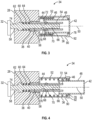
FIG. 3 is a schematic illustration of an embodiment of a jam indicator in a retracted position; -
FIG. 4 is a schematic illustration of an embodiment of a jam indicator in an extended position; -
FIG. 5 is a schematic illustration of an embodiment of a jam indicator during activation; -
FIG. 6 is a schematic illustration of an embodiment of a jam indicator in a partially retracted position; -
FIG. 7 is a side view of an embodiment of a retaining feature of a jam indicator; -
FIG. 8 is a side view of another embodiment of a retaining feature of a jam indicator; -
FIG. 9 is a schematic illustration of yet another embodiment of a retaining feature of a jam indicator; and -
FIG. 10 is a plan view of an embodiment of a retaining feature of a jam indicator. - A detailed description of one or more embodiments of the disclosed apparatus and method are presented herein by way of exemplification and not limited with reference to the Figures.
- Referring to
FIG. 1 , shown is a schematic illustration of an embodiment of a controlsurface actuation system 10 for, for example, an aircraft. Thesystem 10 includes acontrol surface 12, for example, a slat, a flap or a vane, operably connected to arotary actuator 14, for example, a mechanical, electro-mechanical, hydraulic or electro-hydraulic actuator. In some embodiments, thecontrol surface 12 is operably connected to theactuator 14 via arack 16 andpinion 18 arrangement. Operation of theactuator 14 rotates thepinion 18 about apinion axis 20, moving the rack relative to thepinion 18, and thus moving thecontrol surface 12. One skilled in the art will readily appreciate that while arack 16 andpinion 18 arrangement is illustrated and described herein, other arrangements may be utilized to operably connect theactuator 14 to thecontrol surface 12. - Referring now to
FIG. 2 , when theactuator 14 exceeds a torque threshold during a jam event, a torque limiter within the actuator acts to isolate the downstream components and divert the overload to an earth structure while a jam is indicated by ajam indicator mechanism 34 which may indicate potential damage to thesystem 10. The torque limiter within theactuator 14 includesballs 24 positioned indetents 26 in theoutput shaft 28 of theactuator 14. When theactuator 14 is subjected to an overtorque or jam condition, theballs 24 climb thedetents 26 along an actuatoraxial direction 30, and pushes asleeve 32 along the same actuatoraxial direction 30. Movement of thissleeve 32 in turn triggers activation of ajam indicator 34 fixed to theactuator housing 33. - Referring to
FIG. 3 , illustrated is an embodiment of ajam indicator 34 in a set position, not indicating a jam condition of theactuator 14. Though the apparatus is described herein as a jam indicator, one skilled in the art will readily appreciate that the present indicator may be utilized in other applications where a small motion is mechanically detected and mechanically amplified and indicated via a push button. Thejam indicator 34 includes anindicator housing 36 fixed relative to theactuator housing 28. In some embodiments, theindicator housing 36 includes anindicator thread 38 receivable into acomplimentary actuator thread 40 in theactuator housing 28 to secure theindicator housing 36 at theactuator housing 28. Apush button 42 is located inside theindicator housing 36 and the position of thepush button 42 relative toindicator housing 36 is a visual indication of whether or not theactuator 14 has been subjected to an overtorque or jam condition. When thepush button 42 is in a retracted position as inFIG. 3 , thejam indicator 34 indicates that theactuator 14 has not been subjected to an overtorque or jam condition. On the other hand, when thepush button 42 is in an extended position as shown inFIG. 4 , thejam indicator 34 indicates that theactuator 14 has been subjected to an overtorque or jam condition. - Referring again to
FIG. 3 , thepush button 42 is biased toward the extended position by aspring 44 disposed in theindicator housing 36. In some embodiments thespring 44 is interactive with apush button flange 46 extending radially outwardly from apush button body 48, relative to an indicatorcentral axis 50. Theindicator housing 36 includes anouter sleeve 52 defining an outer surface of theindicator housing 36, and aninner sleeve 54 located radially inboard and spaced apart from theouter sleeve 52. In some embodiments, such as shown inFIG. 3 , thepush button body 48 is positioned radially between theinner sleeve 54 and theouter sleeve 52, and thespring 44 is located radially between thepush button body 48 and theouter sleeve 52. In some embodiments, ahousing end 78 of theindicator housing 36 is installed to ahousing body 90 of theindicator housing 36 via a threaded joint 92, allowing for ease of assembly and installation of the various components into theindicator housing 36. - Referring again to
FIG. 3 , thejam indicator 34 further includes aplunger 56 positioned radially inside of theinner sleeve 54. Theplunger 56 extends through ahousing opening 58 axially toward thesleeve 32 and is interactive therewith as will be described further below. Theplunger 56 is biased toward an extended position, as illustrated inFIG. 3 , by a biasing element, such as aplunger spring 60 located axially between aplunger flange 62 and ahousing end 64. Theplunger 56 includes aplunger body 66 that extends axially inside theinner sleeve 54 toward thepush button 42. Thepush button 42 is retained in the retracted position by one or more retainingballs 68 located in a ball opening 70 in theinner sleeve 54. When theplunger 56 is in the extended position theplunger body 66 urges the retainingballs 68 radially outwardly in the ball opening 70. In this position, the retainingballs 68 interfere with a retaining feature of thepush button 42. In some embodiments, such as shown inFIG. 3 , the retaining feature is a retainingflange 72 extending radially inwardly. As will be described further, in other embodiments other retaining features may be utilized. Referring now toFIG. 5 , in the event of an overload, thesleeve 32 of the torque limiter pushes aplunger tip 74 of theplunger 56, theplunger 56 overcomes the biasing force of theplunger spring 60 and moves axially toward a retracted position. The axial movement of theplunger 56 allows the retainingballs 68 to move radially inwardly into aplunger pocket 76 in theplunger body 66. As such, the retainingballs 68 move out of contact with the retainingflange 72 allowing thepush button 42 to move axially toward the extended position. - Referring now to
FIG. 4 , when thepush button 42 is in the fully extended position, thepush button flange 46 contacts thehousing end 78 of theindicator housing 36, thus stopping axial travel of thepush button 42. When the overload is released thesleeve 32 of theactuator 14 moves away from theplunger tip 74 and theplunger spring 60 again urges theplunger 56 towards the extended position, thus urging the retainingballs 68 radially outwardly in theball openings 70. - Referring now to
FIG. 6 , to reset thepush button 42, it is necessary to push thepush button 42 axially to overcome the biasing force of thespring 44 and move the retainingfeature 72 axially past the retainingballs 68. As such, in some embodiments, such as inFIG. 6 ,7 and 8 , the retainingfeature 72 is a slotteddisc spring 80, examples of which are illustrated inFIG. 7 and 8 . The disc springs 80 are flexible allowing for movement of the disc springs 80 over and past the retainingballs 68 to reset thepush button 42. The disc springs 80, however, provide sufficient retention force to maintain retention of thepush button 42 in the retracted position, until released by movement of theplunger 56. The specific shape, thickness, material and other properties of the disc springs 80 may be varied to achieve the desired flexibility for ease of reset of thepushbutton 42, while providing a required retention force to retain thepush button 42 in the retracted position to prevent inadvertent deployment of thepush button 42. - Another embodiment is illustrated in
FIG. 9 and 10 , in which the retention feature is atine spring 82 formed in thepushbutton 42. Thetine spring 82 includes a plurality of axially extendingtine elements 84, with eachtine element 84 including atine barb 86 extending radially inwardly. Thetine elements 84 are sufficiently flexible to allow thetine elements 84 to move around and past the retainingballs 68, where thetine barbs 86 retain thepush button 42 in the retracted position. The specific shape, thickness, material and other properties of thetine elements 84 and thetine barbs 86 may be varied to achieve the desired flexibility for ease of reset of thepushbutton 42, while providing a required retention force to retain thepush button 42 in the retracted position to prevent inadvertent deployment of thepush button 42. - The
jam indicator 34 configurations disclosed herein provide a compact solution that reduces volume and weight of the mechanism, relative to prior art solutions. It is scalable, allowing for use wherever a small movement can be mechanically sensed and mechanically amplified and indicated through a compact push button. Further, the moving parts are contained in a housing, thus not exposed to harsh operating environments. - The term "about" is intended to include the degree of error associated with measurement of the particular quantity based upon the equipment available at the time of filing the application.
- The terminology used herein is for the purpose of describing particular embodiments only and is not intended to be limiting of the present disclosure. As used herein, the singular forms "a", "an" and "the" are intended to include the plural forms as well, unless the context clearly indicates otherwise. It will be further understood that the terms "comprises" and/or "comprising," when used in this specification, specify the presence of stated features, integers, steps, operations, elements, and/or components, but do not preclude the presence or addition of one or more other features, integers, steps, operations, element components, and/or groups thereof.
- While the present disclosure has been described with reference to an exemplary embodiment or embodiments, it will be understood by those skilled in the art that various changes may be made and equivalents may be substituted for elements thereof without departing from the scope of the present disclosure. In addition, many modifications may be made to adapt a particular situation or material to the teachings of the present disclosure without departing from the essential scope thereof. Therefore, it is intended that the present disclosure not be limited to the particular embodiment disclosed as the best mode contemplated for carrying out this present disclosure, but that the present disclosure will include all embodiments falling within the scope of the claims.
Claims (15)
- A motion indicator, comprising:a housing (36);a plunger (56) extending from a first housing end of the housing (36) and axially movable relative to the housing (36), the plunger (56) biased into an axially extended position relative to the housing (36) via a plunger biasing element, the plunger (56) configured to detect motion of a component adjacent to a plunger tip;a push button (42) disposed at a second housing end of the housing (36) and axially moveable relative to the housing (36), the push button (42) biased toward an axially extended position relative to the housing (36) via a biasing element;a retaining assembly configured to retain the push button (42) in an axially retracted position relative to the housing (36);wherein the retaining assembly is configured to release the push button (42) and allow the button biasing element to urge the push button (42) toward the axially extended position when the plunger (56) is urged toward a retracted position via motion of the component adjacent to the plunger tip.
- The motion indicator of claim 1, wherein the housing (36) includes:an outer sleeve; andand an inner sleeve disposed radially inboard of the outer sleeve;wherein the push button (42) is located radially between the outer sleeve and the inner sleeve; andwherein the inner sleeve is located radially between the plunger (56) and the push button (42).
- The motion indicator of claim 2, wherein the retaining assembly includes:one or more retaining balls disposed in a ball opening in the inner sleeve; andone or more retaining elements extending radially inwardly from the push button body to interact with the one or more retaining balls and retain the push button (42) in the retracted position.
- The motion indicator of claim 3, wherein the one or more retaining balls are configured to move radially inwardly when the plunger (56) is urged toward the retracted position, thus releasing the push button (42).
- The motion indicator of claim 3, wherein the one or more retaining elements includes one or more disc springs, or wherein the one or more retaining elements includes one or more tine springs.
- The motion indicator of any preceding claim, wherein the spring element is axially retained between a housing wall and a flange of the push button (42).
- A method of indicating motion of a component, comprising:locating a plunger (56) of a position indicator adjacent the component, the plunger (56) disposed in a housing (36) and extending from a first housing end of the housing and axially movable relative to the housing (36), the plunger (56) biased into an axially extended position relative to the housing (36) via a plunger biasing element;urging the plunger (56) toward a retracted position via motion of the component toward the plunger (56);releasing a retainer of a push button (42) disposed in the housing (36) via movement of the plunger (56) toward the retracted position, the push button (42) disposed at a second housing end of the housing and axially moveable relative to the housing (36), the push button (42) biased toward an axially extended position relative to the housing (36) via a biasing element; andurging the push button (42) toward the axially extended position via the biasing element thereby indicating motion of the component.
- The method of claim 7, wherein the housing (36) includes:an outer sleeve; andand an inner sleeve disposed radially inboard of the outer sleeve; andfurther comprising positioning the push button (42) radially between the outer sleeve and the inner sleeve; andlocating the inner sleeve radially between the plunger (56) and the push button (42).
- The method of claim 8, wherein the retaining assembly includes one or more retaining balls disposed in a ball opening in the inner sleeve; and
retaining the push button (42) in the retracted position via interaction between one or more retaining elements extending radially inwardly from the housing (36) and the one or more retaining balls, and optionally further comprising moving the one or more retaining balls radially inwardly when the plunger (56) is urged toward the retracted position, thus releasing the push button (42), and/or wherein the one or more retaining elements includes one or more disc springs, or wherein the one or more retaining elements includes one or more tine springs. - The method of any of claims 7 to 9, wherein the spring element is axially retained between a housing wall and a flange of the push button (42).
- A control surface actuation system, comprising:an actuator operably connected to a control surface;a jam detecting apparatus of the actuator including an actuator sleeve configured to move axially along an actuator housing when the actuator is subjected to one of an overtorque or jam condition;a jam indicator in operable communication with the actuator sleeve, the jam indicator including:an indicator housing;a plunger (56) extending from a first housing end of the indicator housing and axially movable relative to the indicator housing, the plunger (56) biased into an axially extended position relative to the indicator housing via a plunger biasing element, the plunger (56) configured to detect motion of a component adjacent to a plunger tip;a push button (42) disposed at a second housing end of the indicator housing and axially moveable relative to the indicator housing, the push button (42) biased toward an axially extended position relative to theindicator housing via a button biasing element;a retaining assembly configured to retain the push button (42) in an axially retracted position relative to the indicator housing;wherein the retaining assembly is configured to release the push button (42) and allow the button biasing element to urge the push button (42) toward the axially extended position when the plunger (56) is urged toward a retracted position via motion of the component adjacent to the plunger tip, thereby indicating that the actuator has been subjected to one of an overtorque or jam condition.
- The system of claim 11, wherein the indicator housing includes:an outer sleeve; andand an inner sleeve disposed radially inboard of the outer sleeve;wherein the push button (42) is located radially between the outer sleeve and the inner sleeve; andwherein the inner sleeve is located radially between the plunger (56) and the push button (42).
- The system of claim 12, wherein the retaining assembly includes:one or more retaining balls disposed in a ball opening in the inner sleeve; andone or more retaining elements extending radially inwardly from the indicator housing to interact with the one or more retaining balls and retain the push button (42) in the retracted position.
- The system of claim 13, wherein the one or more retaining balls are configured to move radially inwardly when the plunger (56) is urged toward the retracted position, thus releasing the push button (42), or wherein the one or more retaining elements includes one or more disc springs or one or more tine springs.
- The system of claim of any of claims 11 to 14, wherein the button spring element is axially retained between an indicator housing wall and a flange of the push button (42).
Applications Claiming Priority (1)
| Application Number | Priority Date | Filing Date | Title |
|---|---|---|---|
| IN202311010117 | 2023-02-15 |
Publications (2)
| Publication Number | Publication Date |
|---|---|
| EP4417522A1 true EP4417522A1 (en) | 2024-08-21 |
| EP4417522B1 EP4417522B1 (en) | 2026-01-14 |
Family
ID=89977871
Family Applications (1)
| Application Number | Title | Priority Date | Filing Date |
|---|---|---|---|
| EP24157827.7A Active EP4417522B1 (en) | 2023-02-15 | 2024-02-15 | Push button motion indicator mechanism |
Country Status (3)
| Country | Link |
|---|---|
| US (1) | US12600491B2 (en) |
| EP (1) | EP4417522B1 (en) |
| CA (1) | CA3227570A1 (en) |
Families Citing this family (1)
| Publication number | Priority date | Publication date | Assignee | Title |
|---|---|---|---|---|
| US12607223B2 (en) * | 2024-02-09 | 2026-04-21 | Virgin Galactic Holdings, Inc. | Actuator locking system and method |
Citations (4)
| Publication number | Priority date | Publication date | Assignee | Title |
|---|---|---|---|---|
| US4251789A (en) * | 1979-09-04 | 1981-02-17 | General Electric Company | Circuit breaker trip indicator and auxiliary switch combination |
| WO2005001281A2 (en) * | 2003-04-14 | 2005-01-06 | Curtiss-Wright Controls, Inc. | Torque transfer limiting arrangement for a rotational drive shaft |
| US20080185242A1 (en) * | 2007-02-01 | 2008-08-07 | Curtiss Wright Controls Inc. | Torque brake |
| US20210380226A1 (en) * | 2020-06-08 | 2021-12-09 | The Boeing Company | Variable camber trim units, aircraft comprising the same, and associated methods of operation |
Family Cites Families (15)
| Publication number | Priority date | Publication date | Assignee | Title |
|---|---|---|---|---|
| US4026153A (en) * | 1975-08-08 | 1977-05-31 | Pall Corporation | Magnetic pressure indicator with sampling ports |
| US4453449A (en) * | 1981-09-10 | 1984-06-12 | Westinghouse Electric Corp. | Holding apparatus |
| US4579201A (en) | 1983-05-16 | 1986-04-01 | Curtiss Wright Flight Systems, Inc. | Bidirectional, torque-limiting, no-back clutch mechanism |
| US4759750A (en) * | 1986-12-22 | 1988-07-26 | Dlp Inc. | Pressure sensing syringe |
| US5542150A (en) * | 1994-08-30 | 1996-08-06 | Tu; A-Shih | Simple push button type link control structure |
| US5901817A (en) | 1997-04-18 | 1999-05-11 | The Boeing Company | Torque limiter with trip indicator |
| US6823751B1 (en) * | 2002-05-22 | 2004-11-30 | Meter Engineers, Inc. | Sphere or pig detection switch assembly |
| US6861602B2 (en) * | 2003-01-27 | 2005-03-01 | A.L. Hansen Manufacturing Co. | Push button and method for use thereof |
| US7437919B1 (en) * | 2007-04-18 | 2008-10-21 | Min Wu | Multiple-function tire valve cap with low pressure safety indicator |
| US9482255B2 (en) * | 2011-09-21 | 2016-11-01 | Bal Seal Engineering, Inc. | Multi-latching mechanisms and related methods |
| US10031546B2 (en) * | 2014-09-24 | 2018-07-24 | Hamilton Sundstrand Corporation | Visual failure indication for selector lever |
| EP3421831B1 (en) | 2017-06-29 | 2020-07-15 | Hamilton Sundstrand Corporation | Indicator for torque limiter |
| US10894595B1 (en) | 2017-07-25 | 2021-01-19 | Rockwell Collins, Inc. | Spring detent for over-ridable interconnect |
| DE102017118918A1 (en) * | 2017-08-18 | 2019-02-21 | Harting Electric Gmbh & Co. Kg | Push-button lock for a connector housing |
| US12338940B2 (en) * | 2021-02-05 | 2025-06-24 | Enduro Pipeline Services, Inc. | Pig detector |
-
2023
- 2023-05-11 US US18/315,739 patent/US12600491B2/en active Active
-
2024
- 2024-01-29 CA CA3227570A patent/CA3227570A1/en active Pending
- 2024-02-15 EP EP24157827.7A patent/EP4417522B1/en active Active
Patent Citations (4)
| Publication number | Priority date | Publication date | Assignee | Title |
|---|---|---|---|---|
| US4251789A (en) * | 1979-09-04 | 1981-02-17 | General Electric Company | Circuit breaker trip indicator and auxiliary switch combination |
| WO2005001281A2 (en) * | 2003-04-14 | 2005-01-06 | Curtiss-Wright Controls, Inc. | Torque transfer limiting arrangement for a rotational drive shaft |
| US20080185242A1 (en) * | 2007-02-01 | 2008-08-07 | Curtiss Wright Controls Inc. | Torque brake |
| US20210380226A1 (en) * | 2020-06-08 | 2021-12-09 | The Boeing Company | Variable camber trim units, aircraft comprising the same, and associated methods of operation |
Also Published As
| Publication number | Publication date |
|---|---|
| CA3227570A1 (en) | 2025-05-02 |
| US12600491B2 (en) | 2026-04-14 |
| US20240270372A1 (en) | 2024-08-15 |
| EP4417522B1 (en) | 2026-01-14 |
Similar Documents
| Publication | Publication Date | Title |
|---|---|---|
| CN111942573B (en) | Actuator with releasable output lever | |
| EP1262688B1 (en) | Screw actuator | |
| EP2149496A1 (en) | Actuator | |
| EP4417522B1 (en) | Push button motion indicator mechanism | |
| EP3275789B1 (en) | Actuator assembly | |
| US6843265B2 (en) | Pressure relief system with supply activated valve | |
| EP2311731A1 (en) | Thurst reverser actuation | |
| US20080185242A1 (en) | Torque brake | |
| US4628752A (en) | Actuators and actuator assemblies | |
| US9816632B2 (en) | Actuated valve system triggered by the failure of a collapsible pin under overpressure condition | |
| US10900526B2 (en) | Braking device | |
| US12553499B2 (en) | Linear actuator | |
| EP4282766B1 (en) | High lift skew system | |
| EP0303399B1 (en) | Coupling for a linear displacement transducer | |
| EP3617060A1 (en) | Electric actuator device | |
| US12134374B2 (en) | Braking device | |
| BR102024002485A2 (en) | MOTION INDICATOR, METHOD FOR INDICATING MOTION OF A COMPONENT, AND, CONTROL SURFACE ACTUATOR SYSTEM | |
| EP3421831A1 (en) | Indicator for torque limiter |
Legal Events
| Date | Code | Title | Description |
|---|---|---|---|
| PUAI | Public reference made under article 153(3) epc to a published international application that has entered the european phase |
Free format text: ORIGINAL CODE: 0009012 |
|
| STAA | Information on the status of an ep patent application or granted ep patent |
Free format text: STATUS: THE APPLICATION HAS BEEN PUBLISHED |
|
| AK | Designated contracting states |
Kind code of ref document: A1 Designated state(s): AL AT BE BG CH CY CZ DE DK EE ES FI FR GB GR HR HU IE IS IT LI LT LU LV MC ME MK MT NL NO PL PT RO RS SE SI SK SM TR |
|
| STAA | Information on the status of an ep patent application or granted ep patent |
Free format text: STATUS: REQUEST FOR EXAMINATION WAS MADE |
|
| 17P | Request for examination filed |
Effective date: 20250220 |
|
| GRAP | Despatch of communication of intention to grant a patent |
Free format text: ORIGINAL CODE: EPIDOSNIGR1 |
|
| STAA | Information on the status of an ep patent application or granted ep patent |
Free format text: STATUS: GRANT OF PATENT IS INTENDED |
|
| RIC1 | Information provided on ipc code assigned before grant |
Ipc: B64D 45/00 20060101AFI20250929BHEP Ipc: F16J 1/00 20060101ALI20250929BHEP Ipc: G01L 5/00 20060101ALI20250929BHEP |
|
| INTG | Intention to grant announced |
Effective date: 20251020 |
|
| GRAS | Grant fee paid |
Free format text: ORIGINAL CODE: EPIDOSNIGR3 |
|
| GRAA | (expected) grant |
Free format text: ORIGINAL CODE: 0009210 |
|
| STAA | Information on the status of an ep patent application or granted ep patent |
Free format text: STATUS: THE PATENT HAS BEEN GRANTED |
|
| AK | Designated contracting states |
Kind code of ref document: B1 Designated state(s): AL AT BE BG CH CY CZ DE DK EE ES FI FR GB GR HR HU IE IS IT LI LT LU LV MC ME MK MT NL NO PL PT RO RS SE SI SK SM TR |
|
| REG | Reference to a national code |
Ref country code: CH Ref legal event code: F10 Free format text: ST27 STATUS EVENT CODE: U-0-0-F10-F00 (AS PROVIDED BY THE NATIONAL OFFICE) Effective date: 20260114 Ref country code: GB Ref legal event code: FG4D |
|
| REG | Reference to a national code |
Ref country code: DE Ref legal event code: R096 Ref document number: 602024001978 Country of ref document: DE |
|
| REG | Reference to a national code |
Ref country code: IE Ref legal event code: FG4D |
|
| PGFP | Annual fee paid to national office [announced via postgrant information from national office to epo] |
Ref country code: AT Payment date: 20260301 Year of fee payment: 3 |
|
| REG | Reference to a national code |
Ref country code: NL Ref legal event code: MP Effective date: 20260114 |
|
| PG25 | Lapsed in a contracting state [announced via postgrant information from national office to epo] |
Ref country code: NL Free format text: LAPSE BECAUSE OF FAILURE TO SUBMIT A TRANSLATION OF THE DESCRIPTION OR TO PAY THE FEE WITHIN THE PRESCRIBED TIME-LIMIT Effective date: 20260114 |
|
| REG | Reference to a national code |
Ref country code: AT Ref legal event code: MK05 Ref document number: 1876996 Country of ref document: AT Kind code of ref document: T Effective date: 20260114 |
|
| PG25 | Lapsed in a contracting state [announced via postgrant information from national office to epo] |
Ref country code: RS Free format text: LAPSE BECAUSE OF FAILURE TO SUBMIT A TRANSLATION OF THE DESCRIPTION OR TO PAY THE FEE WITHIN THE PRESCRIBED TIME-LIMIT Effective date: 20260414 |
|
| PG25 | Lapsed in a contracting state [announced via postgrant information from national office to epo] |
Ref country code: ES Free format text: LAPSE BECAUSE OF FAILURE TO SUBMIT A TRANSLATION OF THE DESCRIPTION OR TO PAY THE FEE WITHIN THE PRESCRIBED TIME-LIMIT Effective date: 20260114 |
|
| PG25 | Lapsed in a contracting state [announced via postgrant information from national office to epo] |
Ref country code: PL Free format text: LAPSE BECAUSE OF FAILURE TO SUBMIT A TRANSLATION OF THE DESCRIPTION OR TO PAY THE FEE WITHIN THE PRESCRIBED TIME-LIMIT Effective date: 20260114 |
|
| PG25 | Lapsed in a contracting state [announced via postgrant information from national office to epo] |
Ref country code: GR Free format text: LAPSE BECAUSE OF FAILURE TO SUBMIT A TRANSLATION OF THE DESCRIPTION OR TO PAY THE FEE WITHIN THE PRESCRIBED TIME-LIMIT Effective date: 20260415 |
|
| REG | Reference to a national code |
Ref country code: LT Ref legal event code: MG9D |
|
| PG25 | Lapsed in a contracting state [announced via postgrant information from national office to epo] |
Ref country code: LT Free format text: LAPSE BECAUSE OF FAILURE TO SUBMIT A TRANSLATION OF THE DESCRIPTION OR TO PAY THE FEE WITHIN THE PRESCRIBED TIME-LIMIT Effective date: 20260114 |
|
| PG25 | Lapsed in a contracting state [announced via postgrant information from national office to epo] |
Ref country code: NO Free format text: LAPSE BECAUSE OF FAILURE TO SUBMIT A TRANSLATION OF THE DESCRIPTION OR TO PAY THE FEE WITHIN THE PRESCRIBED TIME-LIMIT Effective date: 20260414 |
|
| PG25 | Lapsed in a contracting state [announced via postgrant information from national office to epo] |
Ref country code: SE Free format text: LAPSE BECAUSE OF FAILURE TO SUBMIT A TRANSLATION OF THE DESCRIPTION OR TO PAY THE FEE WITHIN THE PRESCRIBED TIME-LIMIT Effective date: 20260114 Ref country code: AT Free format text: LAPSE BECAUSE OF FAILURE TO SUBMIT A TRANSLATION OF THE DESCRIPTION OR TO PAY THE FEE WITHIN THE PRESCRIBED TIME-LIMIT Effective date: 20260114 Ref country code: FI Free format text: LAPSE BECAUSE OF FAILURE TO SUBMIT A TRANSLATION OF THE DESCRIPTION OR TO PAY THE FEE WITHIN THE PRESCRIBED TIME-LIMIT Effective date: 20260114 |
|
| PG25 | Lapsed in a contracting state [announced via postgrant information from national office to epo] |
Ref country code: HR Free format text: LAPSE BECAUSE OF FAILURE TO SUBMIT A TRANSLATION OF THE DESCRIPTION OR TO PAY THE FEE WITHIN THE PRESCRIBED TIME-LIMIT Effective date: 20260114 |
|
| PG25 | Lapsed in a contracting state [announced via postgrant information from national office to epo] |
Ref country code: PT Free format text: LAPSE BECAUSE OF FAILURE TO SUBMIT A TRANSLATION OF THE DESCRIPTION OR TO PAY THE FEE WITHIN THE PRESCRIBED TIME-LIMIT Effective date: 20260514 Ref country code: IS Free format text: LAPSE BECAUSE OF FAILURE TO SUBMIT A TRANSLATION OF THE DESCRIPTION OR TO PAY THE FEE WITHIN THE PRESCRIBED TIME-LIMIT Effective date: 20260514 |
|
| PGFP | Annual fee paid to national office [announced via postgrant information from national office to epo] |
Ref country code: FR Payment date: 20260529 Year of fee payment: 3 |
|
| PG25 | Lapsed in a contracting state [announced via postgrant information from national office to epo] |
Ref country code: LV Free format text: LAPSE BECAUSE OF FAILURE TO SUBMIT A TRANSLATION OF THE DESCRIPTION OR TO PAY THE FEE WITHIN THE PRESCRIBED TIME-LIMIT Effective date: 20260114 |
|
| PG25 | Lapsed in a contracting state [announced via postgrant information from national office to epo] |
Ref country code: BG Free format text: LAPSE BECAUSE OF FAILURE TO SUBMIT A TRANSLATION OF THE DESCRIPTION OR TO PAY THE FEE WITHIN THE PRESCRIBED TIME-LIMIT Effective date: 20260114 |