EP4417463A1 - Evaluation system for remanufacturing battery system of electric vehicle and operating method thereof - Google Patents
Evaluation system for remanufacturing battery system of electric vehicle and operating method thereof Download PDFInfo
- Publication number
- EP4417463A1 EP4417463A1 EP23887154.5A EP23887154A EP4417463A1 EP 4417463 A1 EP4417463 A1 EP 4417463A1 EP 23887154 A EP23887154 A EP 23887154A EP 4417463 A1 EP4417463 A1 EP 4417463A1
- Authority
- EP
- European Patent Office
- Prior art keywords
- battery system
- electronic device
- battery
- current
- remaining lifespan
- Prior art date
- Legal status (The legal status is an assumption and is not a legal conclusion. Google has not performed a legal analysis and makes no representation as to the accuracy of the status listed.)
- Pending
Links
Images




Classifications
-
- G—PHYSICS
- G01—MEASURING; TESTING
- G01R—MEASURING ELECTRIC VARIABLES; MEASURING MAGNETIC VARIABLES
- G01R31/00—Arrangements for testing electric properties; Arrangements for locating electric faults; Arrangements for electrical testing characterised by what is being tested not provided for elsewhere
- G01R31/36—Arrangements for testing, measuring or monitoring the electrical condition of accumulators or electric batteries, e.g. capacity or state of charge [SoC]
- G01R31/392—Determining battery ageing or deterioration, e.g. state of health
-
- B—PERFORMING OPERATIONS; TRANSPORTING
- B60—VEHICLES IN GENERAL
- B60L—PROPULSION OF ELECTRICALLY-PROPELLED VEHICLES; SUPPLYING ELECTRIC POWER FOR AUXILIARY EQUIPMENT OF ELECTRICALLY-PROPELLED VEHICLES; ELECTRODYNAMIC BRAKE SYSTEMS FOR VEHICLES IN GENERAL; MAGNETIC SUSPENSION OR LEVITATION FOR VEHICLES; MONITORING OPERATING VARIABLES OF ELECTRICALLY-PROPELLED VEHICLES; ELECTRIC SAFETY DEVICES FOR ELECTRICALLY-PROPELLED VEHICLES
- B60L58/00—Methods or circuit arrangements for monitoring or controlling batteries or fuel cells, specially adapted for electric vehicles
- B60L58/10—Methods or circuit arrangements for monitoring or controlling batteries or fuel cells, specially adapted for electric vehicles for monitoring or controlling batteries
- B60L58/12—Methods or circuit arrangements for monitoring or controlling batteries or fuel cells, specially adapted for electric vehicles for monitoring or controlling batteries responding to state of charge [SoC]
-
- B—PERFORMING OPERATIONS; TRANSPORTING
- B60—VEHICLES IN GENERAL
- B60L—PROPULSION OF ELECTRICALLY-PROPELLED VEHICLES; SUPPLYING ELECTRIC POWER FOR AUXILIARY EQUIPMENT OF ELECTRICALLY-PROPELLED VEHICLES; ELECTRODYNAMIC BRAKE SYSTEMS FOR VEHICLES IN GENERAL; MAGNETIC SUSPENSION OR LEVITATION FOR VEHICLES; MONITORING OPERATING VARIABLES OF ELECTRICALLY-PROPELLED VEHICLES; ELECTRIC SAFETY DEVICES FOR ELECTRICALLY-PROPELLED VEHICLES
- B60L58/00—Methods or circuit arrangements for monitoring or controlling batteries or fuel cells, specially adapted for electric vehicles
- B60L58/10—Methods or circuit arrangements for monitoring or controlling batteries or fuel cells, specially adapted for electric vehicles for monitoring or controlling batteries
- B60L58/16—Methods or circuit arrangements for monitoring or controlling batteries or fuel cells, specially adapted for electric vehicles for monitoring or controlling batteries responding to battery ageing, e.g. to the number of charging cycles or the state of health [SoH]
-
- G—PHYSICS
- G01—MEASURING; TESTING
- G01R—MEASURING ELECTRIC VARIABLES; MEASURING MAGNETIC VARIABLES
- G01R31/00—Arrangements for testing electric properties; Arrangements for locating electric faults; Arrangements for electrical testing characterised by what is being tested not provided for elsewhere
- G01R31/36—Arrangements for testing, measuring or monitoring the electrical condition of accumulators or electric batteries, e.g. capacity or state of charge [SoC]
- G01R31/385—Arrangements for measuring battery or accumulator variables
- G01R31/3865—Arrangements for measuring battery or accumulator variables related to manufacture, e.g. testing after manufacture
-
- G—PHYSICS
- G01—MEASURING; TESTING
- G01R—MEASURING ELECTRIC VARIABLES; MEASURING MAGNETIC VARIABLES
- G01R31/00—Arrangements for testing electric properties; Arrangements for locating electric faults; Arrangements for electrical testing characterised by what is being tested not provided for elsewhere
- G01R31/36—Arrangements for testing, measuring or monitoring the electrical condition of accumulators or electric batteries, e.g. capacity or state of charge [SoC]
- G01R31/389—Measuring internal impedance, internal conductance or related variables
-
- H—ELECTRICITY
- H02—GENERATION; CONVERSION OR DISTRIBUTION OF ELECTRIC POWER
- H02J—ELECTRIC POWER NETWORKS; CIRCUIT ARRANGEMENTS OR SYSTEMS FOR SUPPLYING OR DISTRIBUTING ELECTRIC POWER; SYSTEMS FOR STORING ELECTRIC ENERGY
- H02J7/00—Circuit arrangements for charging or discharging batteries or for supplying loads from batteries
- H02J7/80—Circuit arrangements for charging or discharging batteries or for supplying loads from batteries including monitoring or indicating arrangements
- H02J7/84—Control of state of health [SOH]
-
- G—PHYSICS
- G01—MEASURING; TESTING
- G01R—MEASURING ELECTRIC VARIABLES; MEASURING MAGNETIC VARIABLES
- G01R31/00—Arrangements for testing electric properties; Arrangements for locating electric faults; Arrangements for electrical testing characterised by what is being tested not provided for elsewhere
- G01R31/36—Arrangements for testing, measuring or monitoring the electrical condition of accumulators or electric batteries, e.g. capacity or state of charge [SoC]
- G01R31/367—Software therefor, e.g. for battery testing using modelling or look-up tables
-
- G—PHYSICS
- G01—MEASURING; TESTING
- G01R—MEASURING ELECTRIC VARIABLES; MEASURING MAGNETIC VARIABLES
- G01R31/00—Arrangements for testing electric properties; Arrangements for locating electric faults; Arrangements for electrical testing characterised by what is being tested not provided for elsewhere
- G01R31/36—Arrangements for testing, measuring or monitoring the electrical condition of accumulators or electric batteries, e.g. capacity or state of charge [SoC]
- G01R31/385—Arrangements for measuring battery or accumulator variables
- G01R31/387—Determining ampere-hour charge capacity or SoC
-
- Y—GENERAL TAGGING OF NEW TECHNOLOGICAL DEVELOPMENTS; GENERAL TAGGING OF CROSS-SECTIONAL TECHNOLOGIES SPANNING OVER SEVERAL SECTIONS OF THE IPC; TECHNICAL SUBJECTS COVERED BY FORMER USPC CROSS-REFERENCE ART COLLECTIONS [XRACs] AND DIGESTS
- Y02—TECHNOLOGIES OR APPLICATIONS FOR MITIGATION OR ADAPTATION AGAINST CLIMATE CHANGE
- Y02E—REDUCTION OF GREENHOUSE GAS [GHG] EMISSIONS, RELATED TO ENERGY GENERATION, TRANSMISSION OR DISTRIBUTION
- Y02E60/00—Enabling technologies; Technologies with a potential or indirect contribution to GHG emissions mitigation
- Y02E60/10—Energy storage using batteries
Definitions
- the present invention relates to an evaluation system for remanufacturing of an electric vehicle battery system and a method of operating the same.
- a secondary battery is a battery that can be repeatedly charged and discharged.
- the field where these secondary batteries are most widely used is the electric vehicle field. Electric vehicles are driven using electrical energy generated from a mounted secondary battery.
- the replaced secondary battery is not immediately discarded, but can be reused as a battery for electric vehicles, considering the remaining lifespan or condition thereof, or used as a battery for other purposes through remanufacturing.
- a method of accurately evaluating the conditions of the reused or remanufactured batteries is required.
- the present invention has been made in view of the above problems, and it is one object of the present invention to provide an evaluation system for remanufacturing of an electric vehicle battery system that is capable of evaluating state of health (SOH) representing the remaining lifespan of a battery system and a method of operating the evaluation system.
- SOH state of health
- an evaluation system for remanufacturing of a battery system including a charger/discharger connected to the battery system and used to charge and discharge the battery system; and an electronic device connected to the charger/discharger, receiving data about the battery system from the charger/discharger, and evaluating a remaining lifespan of the battery system based on the received data, wherein the electronic device selects at least one of a regular method and a simple method based on an input of a user, and the electronic device evaluates a remaining lifespan of the battery system according to the at least one method selected above.
- state of health (SOH) representing the remaining lifespan of a battery system can be evaluated.
- first and second are used herein merely to describe a variety of constituent elements, but the constituent elements are not limited by the terms. The terms are used only for the purpose of distinguishing one constituent element from another constituent element. For example, a first element may be termed a second element and a second element may be termed a first element without departing from the teachings of the present invention.
- the term “and/or” includes any or all combinations of one or more of the associated listed items.
- FIG. 1 shows a battery remanufacturing process according to embodiments of the present invention.
- a replaced battery e.g., waste battery
- a receipt number is assigned to the received battery and an identification tag is attached thereto.
- the received battery is subjected to a cleaning process. During the cleaning process, the battery case is cleaned and foreign substances and dust attached to the case are removed.
- receipt inspection of the battery is performed.
- the receipt inspection includes visual inspection performed by examining the appearance of the battery with the naked eye, airtightness inspection to determine whether the airtightness of the battery is maintained, cooling passage inspection performed on a cooling passage for battery cooling, communication inspection performed on the communication capability of the battery, and inspection performed on the overall condition of the battery. Depending on the receipt inspection results, it is decided whether to remanufacture the battery or discard the battery. Batteries that do not meet prescribed standards may be discarded after receipt inspection.
- the battery that passes the receipt inspection is subject to a disassembly process.
- the parts of the battery are disassembled, and parts to be reused and parts to be discarded are sorted out. Additional cleaning is performed on the parts to be reused.
- the disassembled battery is reassembled.
- the disassembled battery may be assembled into a battery that fits a specific standard or specific purpose.
- Basic inspections may be performed on the assembled battery. For example, airtightness inspection, cooling passage inspection, and communication inspection may be performed on the assembled battery.
- the battery condition is evaluated.
- the remaining lifespan (SOH, state of health) of the battery is evaluated.
- SOH state of health
- At least one of various methods for evaluating the remaining lifespan of the battery may be selected. Based on the at least one method, the remaining lifespan of the battery may be evaluated. Accordingly, the remaining lifespan of the battery may be evaluated efficiently and accurately.
- the battery is shipped after a pre-shipment inspection is performed.
- the latest condition of the battery is checked before shipment through shipping inspection (e.g., the condition of the battery and the presence of any problems are checked through communication inspection, and appearance and airtightness inspection are performed).
- a shipping code e.g., remanufacturing number
- shipping documents are created, the battery is packaged, and final transportation begins.
- the present invention relates to an evaluation system for remanufacturing of an electric vehicle battery system that is capable of evaluating the remaining lifespan of the remanufactured battery more effectively and accurately and a method of operating the evaluation system.
- FIG. 2 shows an evaluation system according to embodiments of the present invention.
- an evaluation system 10 may include a test device 100, a data analysis device 200, a battery system 300, and a charger/discharger 400.
- the test device 100 may perform tests on the battery system 300.
- the test device 100 may be electrically connected to the battery system 300 to obtain data related to the condition of the battery system 300. According to embodiments, the test device 100 may obtain data on the current condition of the battery system 300.
- the test device 100 may be a cycler, but the present invention is not limited thereto.
- the data analysis device 200 may receive and store data obtained from the test device 100.
- the data analysis device 200 may analyze (or interpret) data about the stored battery system 300. According to embodiments, the data analysis device 200 may calculate the remaining lifespan of the battery system 300 using various data about the battery system 300 transmitted from the test device 100. The data analysis device 200 according to embodiments of the present invention may calculate the remaining lifespan of the battery system 300 in various methods (or modes). At this time, the calculation of the remaining lifespan of the battery system 300 may be performed for each cell included in the battery system 300, or may be performed for a module including at least two of the cells.
- test device 100 and the data analysis device 200 are shown as being configured separately. However, according to embodiments, the test device 100 and the data analysis device 200 may be configured as one test device.
- the battery system 300 may store or discharge electrical energy.
- the battery system 300 may include a secondary battery cell.
- the secondary battery cell may store electrical energy supplied from the outside or supply the stored electrical energy to the outside.
- the battery system 300 may include a plurality of secondary battery cells.
- the battery system 300 may include a controller for controlling or managing a plurality of secondary battery cells.
- the battery system 300 may be an energy storage device, but the present invention is not limited thereto.
- the charger/discharger 400 may charge or discharge the battery system 300. According to embodiments, the charger/discharger 400 may supply alternating current or direct current power to the battery system 300 or receive alternating current or direct current power from the battery system 300. Through this process, the charger/discharger 400 may charge and discharge the battery system 300.
- the charger/discharger 400 may operate under the control of the test device 100 or the data analysis device 200. According to embodiments, the charger/discharger 400 may receive charge/discharge schedule information of the battery system 300 from the test device 100 or the data analysis device 200. Based on the received charge/discharge schedule information, the charger/discharger 400 may charge/discharge the battery system 300.
- FIG. 3 is a diagram explaining the function of a test device according to embodiments of the present invention.
- the test device 100 may include a plurality of modules 110, 120, 130, 140, and 150 (hereinafter referred to as 'modules 110 to 150').
- the modules 110 to 150 are components for performing each function of the test device 100, and may be composed of at least one of hardware performing each function, software, and a combination thereof.
- the test setup module 110 may set the properties of a test for the battery system 300.
- the test setup module 110 may set information (e.g., vehicle model, model year, etc.) about a vehicle equipped with the battery system 300 that is being tested and information on the type (e.g., material (LFP, NMC, NCA, etc.)) and age of the battery system 300).
- the test setup module 110 may set the properties of the test for the battery system 300 based on input from the outside.
- a remaining lifespan evaluation method selection module 120 may set a method for evaluating the remaining lifespan of the battery system 300 by the data analysis device 200.
- the remaining lifespan of the battery system 300 may be evaluated according to a regular method or simple method.
- the regular method is a method of evaluating the remaining lifespan from data on the battery system 300 obtained by fully charging and discharging the battery system 300
- the simple method is a method of evaluating the remaining lifespan from data on the battery system 300 obtained without a complete cycle of fully charging and discharging the battery system 300, for example, without fully discharging.
- the time required for the regular method may be longer than the time required for the simple method.
- the electronic device may evaluate the remaining lifespan of the battery system 300 according to one simple method, or may evaluate the remaining lifespan of the battery system 300 according to two or more simple methods.
- the electronic device may evaluate the overall remaining lifespan of the battery system 300 by combining the evaluated remaining lifespan.
- the electronic device may evaluate the remaining lifespan of the first cells among a plurality of cells included in the battery system 300 using the regular method, may evaluate the remaining lifespan of the second cells using the first simple method, and may evaluate the remaining lifespan of the third cells using the second simple method. At this time, the electronic device may evaluate, as the remaining lifespan of the first cells, the remaining lifespan of the cells that have voltage-current characteristics and remaining lifespan similar to those of the first cells among the second and third cells. Accordingly, the electronic device may more accurately evaluate remaining lifespan.
- a protective motion module 130 may monitor the condition of the battery system 300 and stop charging/discharging or testing of the battery system 300 according to the monitoring results.
- the protective motion module 130 may monitor the voltage, temperature, and current of the battery system 300, and may determine whether the condition of the battery system 300 is abnormal according to the monitoring results. For example, the protective motion module 130 may determine overvoltage, undervoltage, high temperature, low temperature, and voltage deviation of the battery system 300. The protective motion module 130 may control the test device 100 to stop the test on the battery system 300 when an abnormality occurs, or may stop charging and discharging of the battery system 300 by controlling the charger/discharger 400.
- the protective motion module 130 may turn on or turn off a switch (or relay) connecting the battery system 300 and the external devices 100 and 400, thereby controlling the electrical connection between the battery system 300 and the external devices 100 and 400. Through this operation, the protective motion module 130 may stop charging/discharging or testing performed on the battery system 300.
- a data acquisition module 140 may obtain data about the battery system 300.
- the data acquisition module 140 may receive data related to cell voltage, cell current, cell temperature, or condition of the battery system 300 from the battery system 300 or the charger/discharger 400.
- the data acquisition module 140 may receive data related to cell voltage, cell current, cell temperature, or condition of the battery system 300 from a controller (e.g., battery management system (BMS)) included in the battery system 300.
- BMS battery management system
- the data acquisition module 140 may receive data about the battery system 300 from the battery system 300 or the charger/discharger 400 according to a wired communication method or a wireless communication method.
- the data acquisition module 140 may receive data about the battery system 300 according to controller area network (CAN), CAN with flexible data rate (CANFD), local interconnect network (LIN), or an Ethernet method, but the embodiments of the present invention is not limited thereto.
- CAN controller area network
- CANFD CAN with flexible data rate
- LIN local interconnect network
- Ethernet method an Ethernet method
- the data acquisition module 140 may include measurement equipment that is electrically connected to the battery system 300 and measures the voltage, current, or temperature of the battery system 300, and may obtain data about the voltage, current, or temperature of the battery system 300 using the measurement equipment.
- An internal resistance measurement module 150 may measure the internal resistance of the battery system 300. According to embodiments, the internal resistance measurement module 150 may measure alternating current internal resistance (AC IR) or direct current internal resistance (DC IR) of battery cells included in the battery system 300.
- AC IR alternating current internal resistance
- DC IR direct current internal resistance
- the alternating current internal resistance refers to the internal resistance measured under the conditions in which alternating current is applied to the battery system 300 (or battery cell)
- the direct current internal resistance refers to the internal resistance measured under the condition in which direct current is applied to the battery system 300 (or battery cell).
- the internal resistance measurement module 150 may include AC internal resistance measurement equipment for measuring alternating current internal resistance (AC IR), and may measure the alternating current internal resistance (AC IR) of the battery system 300 using AC internal resistance measurement equipment.
- AC IR alternating current internal resistance
- the internal resistance measurement module 150 may measure direct current internal resistance (DC IR) by controlling the charger/discharger 400.
- DC IR direct current internal resistance
- the internal resistance measurement module 150 may be controlled to supply current for measuring alternating current internal resistance (DC IR) to the battery system 300 by controlling the charger/discharger 400.
- FIG. 4 shows a data analysis device according to embodiments of the present invention.
- the data analysis device 200 may include a communicator 210, a controller 220, and a storage 230.
- the communicator 210 may exchange data with an external device.
- the communicator 210 may exchange data with an external device according to a wired communication method or wireless communication method.
- the communicator 210 may exchange data with the test device 100, the battery system 300, or the charger/discharger 400.
- the communicator 210 may receive condition information about the battery system 300 from the test device 100.
- the controller 220 may control the overall operation of the data analysis device 200.
- the controller 220 may include at least one processor, and the at least one processor may be central processing unit (CPU), micro controller unit (MCU), graphical processing unit (GPU), application specified integrated circuit (ASIC), or field programmable gate array (FPGA), but the embodiments of the present invention are not limited thereto.
- CPU central processing unit
- MCU micro controller unit
- GPU graphical processing unit
- ASIC application specified integrated circuit
- FPGA field programmable gate array
- the controller 220 may estimate or calculate the remaining lifespan of the battery system 300 using data related to the condition of the battery system 300 measured or obtained by the test device 100. Unless otherwise stated, the operation of the data analysis device 200 described in this specification may be understood as being performed under the control of the controller 220.
- the storage 230 may store data necessary for the operation of the data analysis device 200.
- the storage 230 may include non-volatile memory or volatile memory.
- the storage 230 may store a plurality of commands for controlling the operation of the data analysis device 200.
- the controller 220 may control the data analysis device 200 by loading the commands stored in the storage 230.
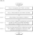
- FIG. 5 is a flowchart for explaining a method of calculating the remaining lifespan of a battery system in a regular method according to embodiments of the present invention.
- the test device 100 or the data analysis device 200 may calculate the remaining lifespan of the battery system 300 using data about the battery system 300.
- the test device 100, the data analysis device 200, or a combination thereof will be referred to and described as an electronic device.
- the electronic device may fully charge the battery system 300 (S 110).
- the electronic device may control the charger/discharger 400 to fully charge the battery system 300.
- full charging means charging to a point where the charge level (state of charge (SOC)) of a battery is 100 %.
- the electronic device may fully discharge the battery system 300 (S120).
- the electronic device may control the charger/discharger 400 to fully discharge the battery system 300.
- full discharging means discharging to a point where the charge level (state of charge (SOC)) of a battery is 0 %.
- the electronic device charges or discharges the battery system 300
- the electronic device controls the charger/discharger 400 connected to the battery system 300 to charge or discharge the battery system 300.
- the electronic device measures the discharge current of the battery system 300 (S130). According to embodiments, the electronic device may obtain information about discharge current discharged from the battery system 300 while the battery system 300 goes from fully charged to fully discharged. At this time, the discharge current may be measured by the test device 100 or the charger/discharger 400.
- the electronic device may calculate the current maximum capacity of the battery system 300 using the relationship between discharge current and voltage (S140). According to embodiments, the electronic device may calculate the current maximum capacity of the battery system 300 using information about the measured discharge current and voltage at the relevant point in time.
- the electronic device may calculate the current maximum capacity of the battery system 300 according to Equation 1 below.
- CMax cur ⁇ V min V max I dis dt
- CMax cur is the current maximum capacity of the battery system 300
- V max is the voltage when the battery system 300 is fully charged
- V min is the voltage when the battery system 300 is fully discharged
- I dis is discharge current
- the electronic device may calculate the remaining lifespan of the battery system 300 using the current maximum capacity and initial maximum capacity of the battery system 300 (S150). According to embodiments, the electronic device may calculate the ratio of the current maximum capacity to the initial maximum capacity of the battery system 300 as remaining lifespan, that is, SOH. Here, information about the initial maximum capacity of the battery system 300 may be stored in advance.
- the electronic device may calculate the remaining lifespan of the battery system 300 according to Equation 2 below.
- SOH CMax cur CMax bol ⁇ 100
- SOH is the remaining lifespan of the battery system 300
- CMax cur is the current maximum capacity of the battery system 300
- CMax bol is the initial maximum capacity of the battery system 300
- 100 is a value to express remaining lifespan in %.
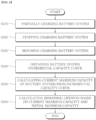
- FIG. 6 is a flowchart for explaining a method of calculating the remaining lifespan of a battery system in a simple method according to embodiments of the present invention.
- the electronic device may partially charge the battery system 300 (S210).
- partial charging means charging to the point where the charge level (state of charge (SOC)) of a battery is less than 100%.
- the electronic device may stop charging the battery system 300 (S220). According to embodiments, the electronic device may stop charging the battery system 300 for a predetermined period of time.
- the electronic device may resume charging the battery system 300 (S230). According to embodiments, the electronic device may charge the battery system 300 to a predetermined charge amount.
- the electronic device may obtain an incremental capacity curve for the battery system 300 (S240).
- the electronic device may obtain data on the current and voltage of the battery system 300 for each time in the charging (or discharging) process of the battery system 300. Based on the obtained data, the electronic device may calculate the ratio (dV/dQ) of the change (dV) in voltage (V) to the change (dQ) in capacity (Q) obtained from current, and may obtain (or calculate) an incremental capacity curve by expressing this ratio (dQ/dV) to voltage (V).
- the electronic device may calculate the current maximum capacity of the battery system 300 from the incremental capacity curve of the battery system 300 (S250). This process will be described later.
- the electronic device may calculate the remaining lifespan of the battery system 300 using the current maximum capacity and initial maximum capacity of the battery system 300 (S260). According to embodiments, the electronic device may calculate the ratio of the current maximum capacity to the initial maximum capacity of the battery system 300 as remaining lifespan, that is, SOH. Here, information about the initial maximum capacity of the battery system 300 may be stored in advance.
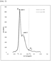
- FIG. 7 is a diagram explaining a method of calculating the remaining lifespan of a battery system in a simple method according to embodiments of the present invention. Referring to FIG. 7 , the incremental capacity curve for the battery system 300 is shown.
- FIG. 7 shows the incremental capacity curve of a lithium-iron phosphate (LiFePO4 (LFP)) battery, and the incremental capacity curve may be obtained according to step S240 of the method described with reference to FIG. 6 . That is, the method described with reference to FIG. 7 may be applied to the LFP battery.
- the incremental capacity curve represents incremental capacity during additional charging after partial charging of the battery system 300 (e.g., up to SOC 50 %).
- the point (P 1 ) represents a point (peak 1) where incremental capacity first reaches the maximum
- the point (P 2 ) represents a point where the battery system 300 reaches an open circuit voltage after the point (P 1 ).
- Voltages (V 1 , V 2 ) are voltages corresponding to the points (P 1 , P 2 ), respectively.
- the electronic device may calculate the current maximum capacity of the battery system 300 by calculating the area below the incremental capacity curve between the points (P 1 , P 2 ). For example, the electronic device may calculate the current maximum capacity of the battery system 300 according to Equation 3 below.
- CMax cur ⁇ 1 ⁇ ⁇ V 1 V 2 IC V dV + ⁇ 1
- CMax cur is the current maximum capacity of the battery system 300
- V 1 is a voltage corresponding to the first local maximum value in the incremental capacity curve
- V 2 is an open circuit voltage
- IC(V) is an incremental capacity curve (or incremental capacity function)
- ⁇ 1 and ⁇ 1 are constants.
- ⁇ 1 and ⁇ 1 may be constants derived from the correlation between the area under the incremental capacity curve and current capacity for each of the various batteries, and may be constants previously stored for each of the battery system 300.
- the electronic device may calculate the remaining lifespan of the battery system 300 using the current maximum capacity and initial maximum capacity of the battery system 300.
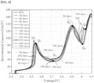
- FIG. 8 is a diagram explaining a method of calculating the remaining lifespan of a battery system in a simple method according to embodiments of the present invention. Referring to FIG. 8 , the incremental capacity curve for the battery system 300 is shown.
- FIG. 8 shows the incremental capacity curve of a lithium-manganese oxide (LMO) battery or nickel-manganese-cobalt (NMC) battery, and the incremental capacity curve may be obtained according to step S240 of the method described with reference to FIG. 6 . That is, the method to be described with reference to FIG. 8 may be applied to the LMO battery or NMC battery.
- LMO lithium-manganese oxide
- NMC nickel-manganese-cobalt
- FIG. 8 shows incremental capacity curves according to the age of the battery system 300. As shown in FIG. 8 , depending on the age of the battery system 300, the incremental capacity curve may vary even for the same battery system 300. For example, the incremental capacity curve of the battery system 300 in the initial condition is different from the incremental capacity curve of the battery system 300 after 30 days. The electronic device may calculate the remaining lifespan of the battery system 300 based on these facts.
- the electronic device may calculate a current incremental capacity curve at the current of the battery system 300 and select an arbitrary point (e.g., Qi) on the incremental capacity curve. Then, the electronic device may determine an incremental capacity value at the selected arbitrary point (Q 1 ) and a point (e.g., Q' 1 ) on the incremental capacity curve at another point corresponding to the selected arbitrary point (Q 1 ), and may calculate current maximum capacity using the incremental capacity values at the two points (Q 1 and Q' 1 ).
- the incremental capacity curve at another point in time may be a past incremental capacity curve at a time in the past before the current, for example, an initial incremental capacity curve at an initial point in time, but the present invention is not limited thereto. However, for convenience of explanation, the initial incremental capacity curve is explained below.
- Information about the initial incremental capacity curve may be stored in advance.
- a point (e.g., Qi) on the current incremental capacity curve and a point (Q'i) on the initial capacity curve corresponding to the point (Qi) may have the same value or the same trend.
- the same trend means that the values of N derivatives (N is a natural number greater than 1) are the same.
- the electronic device may select the first pole point (i.e., the first point where the first derivative of the incremental capacity curve is 0 and the second derivative of the incremental capacity curve is not 0) on the current incremental capacity curve as the point (Qi).
- the first pole point on the initial incremental capacity curve may be selected as the corresponding point (Q' 1 ).
- the electronic device may calculate current maximum capacity according to Equation 4 below.
- CMax cur CMax bol ⁇ 1 ⁇ ⁇ 2 ⁇ IC cur IC bol ⁇ 100 ⁇ 2 100
- CMax cur is the current maximum capacity of the battery system 300
- CMax bol is the initial maximum capacity of the battery system 300
- IC cur is an incremental capacity value at a point (e.g., Qi) on a current incremental capacity curve
- IC bol is an incremental capacity value at a corresponding point (e.g., Q' 1 ) on an initial incremental capacity curve
- ⁇ 2 and ⁇ 2 are constants.
- ⁇ 2 and ⁇ 2 may be constants derived from the correlation between incremental capacity values at various lifespans for each of various batteries, and may be constants pre-stored for the battery system 300.
- the electronic device may calculate current maximum capacity using a voltage value instead of the incremental capacity value of the point of the incremental capacity curve of the battery system 300.
- the electronic device may calculate current maximum capacity using a voltage value at an arbitrary point (e.g., Q 1 ) on a current incremental capacity curve and a voltage value at a point (e.g., Q' 1 ) on an incremental capacity curve at a different time corresponding to the selected arbitrary point (Q 1 ).
- the electronic device may calculate current maximum capacity according to Equation 5 below.
- CMax cur CMax bol ⁇ 1 ⁇ ⁇ 3 ⁇ V cur V bol ⁇ 100 ⁇ 3 100
- CMax cur is the current maximum capacity of the battery system 300
- CMax bol is the initial maximum capacity of the battery system 300
- V cur is a voltage value at the point (e.g., Q 1 ) on a current incremental capacity curve
- V bol a voltage value at the corresponding point (e.g., Q' 1 ) on an initial incremental capacity curve
- ⁇ 3 and ⁇ 3 are constants.
- ⁇ 3 and ⁇ 3 may be constants derived from the correlation between voltage values at various lifespans for each of various batteries, and may be constants pre-stored for the battery system 300.
- the electronic device may calculate the current maximum capacity of the battery system 300 using the value (e.g., incremental capacity value or voltage value) of a pair of points consisting of a point on the current incremental capacity curve and a point on the corresponding initial incremental capacity curve.
- the electronic device may calculate the current maximum capacity of the battery system 300 using a plurality of pairs of points (e.g., Q 2 to Q 5 and corresponding points on the initial incremental capacity curve), each consisting of a point on the current incremental capacity curve and a point on the corresponding initial incremental capacity curve.
- the electronic device may calculate the current maximum capacity using statistics of current maximum capacity values calculated by each of a plurality of pairs of points.
- the electronic device may calculate current maximum capacity according to Equation 6 below.
- CMax cur,total is the overall current maximum capacity of the battery system 300 calculated using a plurality of pairs of points
- CMax cur,i is the current maximum capacity of the battery system 300 calculated from the ith pair of points among the total K (K is a natural number).
- the electronic device may calculate current maximum capacity according to Equation 7 below.
- w is a weight applied to the current maximum capacity of the battery system 300 calculated from the ith pair of points.
- the weight w may be determined based on the difference in voltage values between two points included in the ith pair of points.
- the electronic device may calculate weight w; according to Equation 8 below.
- dist is the difference in voltage values between two points included in the ith pair of points.
- FIG. 9 is a diagram explaining a method of calculating the remaining lifespan of a battery system in a simple method according to embodiments of the present invention.
- the electronic device may partially charge the battery system 300 (S310).
- the electronic device may control the charger/discharger 400 to partially charge the battery system 300.
- the electronic device may stop charging the battery system 300 (S320). According to embodiments, the electronic device may stop charging the battery system 300 for a predetermined period of time.
- the electronic device may receive measurement values for the internal resistance of the battery system 300 (S330).
- measurement values for the internal resistance of the battery system 300 may be measured by a separate internal resistance measurement device and then transmitted from the internal resistance measurement device to the electronic device.
- the internal resistance measurement values may be measurement values for alternating current internal resistance (AC-IR) or direct current internal resistance (DC-IR).
- the electronic device may calculate the current maximum capacity of the battery system 300 using the internal resistance measurement values (S340). According to embodiments, the electronic device may calculate the current maximum capacity of the battery system 300 according to regression analysis using the internal resistance measurement values as variables.
- the electronic device may calculate the current maximum capacity of the battery system 300 according to Equation 9 below.
- CMax cur ⁇ 4 ⁇ IR + ⁇ 4
- CMax cur is the current maximum capacity of the battery system 300
- IR is the internal resistance measurement value of the battery system 300
- ⁇ 4 and ⁇ 4 are constants.
- ⁇ 4 and ⁇ 4 may be constants derived from the correlation between an internal resistance measurement value and capacity for each of various batteries, and may be constants pre-stored for the battery system 300.
- FIG. 10 is a diagram explaining a method of calculating the remaining lifespan of a battery system using the simple method according to embodiments of the present invention.
- the electronic device may charge (or discharge) the battery system 300 to the first charge level (S410). That is, the electronic device may charge or discharge the battery system 300 so that the charge amount of the battery system 300 reaches the first charge level.
- the electronic device may pause charging or discharging the battery system 300 (S420). According to embodiments, the electronic device may stop charging (or discharging) the battery system 300 for a predetermined period of time.
- the electronic device may charge (or discharge) the battery system 300 to the second charge level (S430). When the second charge level is less than the first charge level, the electronic device discharges the battery system 300. When the second charge level is greater than the first charge level, the electronic device charges the battery system 300.
- the electronic device may calculate the current partial capacity of the battery system 300 using the relationship between the charge/discharge current and voltage of the battery system 300 (S440). According to embodiments, the electronic device may calculate the current partial capacity of the battery system 300 using information about the measured charge/discharge current and voltage at the relevant point in time.
- the electronic device may calculate the current partial capacity of the battery system 300 according to Equation 10 below.
- CPar cur ⁇ V 1 V 2 I dt
- CPar cur is the current partial capacity of the battery system 300
- V 1 is a voltage corresponding to the first charge level of the battery system 300
- V 2 is a voltage corresponding to the second charge level of the battery system 300
- I is the charge/discharge current of the battery system 300.
- the electronic device may calculate the current maximum capacity of the battery system 300 from the calculated partial capacity of the battery system 300. For example, the electronic device may calculate the current maximum capacity of the battery system 300 according to Equation 11 below.
- CMax cur ⁇ 5 ⁇ CPar cur + ⁇ 5
- CMax cur is the current maximum capacity of the battery system 300
- CPar cur is the current partial capacity of the battery system 300
- ⁇ 5 and ⁇ 5 are constants.
- ⁇ 5 and ⁇ 5 may be constants derived from the correlation between partial capacity and charge amount for each of various batteries, and may be constants pre-stored for the battery system 300. At this time, ⁇ 5 and ⁇ 5 may vary when the charge amount is different even when the battery system 300 is of the same type.
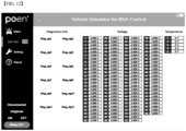
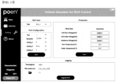
- FIGS. 11 to 13 show the operation screens of the evaluation system according to embodiments of the present invention.
- the screen shown in FIGS. 11 to 13 may be displayed through a display connected to a test device or data analysis device.
- the evaluation system may receive measurement data for each of a plurality of connected battery systems 300 and information on the conditions thereof, and may display the measurement data and the information. For example, the evaluation system may display voltage, temperature, and condition information for each of the battery systems 300.
- the evaluation system may display a screen where a user may select various settings for the battery system.
- the evaluation system may display a screen where a user may set the type of a battery system, the protection function for the battery system, and the data storage path of the battery system.
- the methods according to the embodiments of the present invention may be implemented in the form of a program command that can be executed through various computer means and recorded in a computer-readable medium.
- the computer-readable medium can store program commands, data files, data structures or combinations thereof.
- the program commands recorded in the medium may be specially designed and configured for the present invention or be known to those skilled in the field of computer software.
- Examples of a computer-readable recording medium include magnetic media such as hard disks, floppy disks and magnetic tapes, optical media such as CD-ROMs and DVDs, magnetooptical media such as floptical disks, or hardware devices such as ROMs, RAMs and flash memories, which are specially configured to store and execute program commands.
- Examples of the program commands include machine language code created by a compiler and high-level language code executable by a computer using an interpreter and the like.
- the hardware devices described above may be configured to operate as one or more software modules to perform the operations of the embodiments, and vice versa.
Landscapes
- Engineering & Computer Science (AREA)
- Physics & Mathematics (AREA)
- General Physics & Mathematics (AREA)
- Power Engineering (AREA)
- Life Sciences & Earth Sciences (AREA)
- Sustainable Development (AREA)
- Mechanical Engineering (AREA)
- Transportation (AREA)
- Sustainable Energy (AREA)
- Manufacturing & Machinery (AREA)
- Secondary Cells (AREA)
- Charge And Discharge Circuits For Batteries Or The Like (AREA)
- Data Mining & Analysis (AREA)
- Mathematical Physics (AREA)
- Pure & Applied Mathematics (AREA)
- Mathematical Analysis (AREA)
- Mathematical Optimization (AREA)
- Theoretical Computer Science (AREA)
- Computational Mathematics (AREA)
- Algebra (AREA)
- Evolutionary Biology (AREA)
- Probability & Statistics with Applications (AREA)
- Databases & Information Systems (AREA)
- Software Systems (AREA)
- General Engineering & Computer Science (AREA)
- Operations Research (AREA)
- Bioinformatics & Computational Biology (AREA)
- Bioinformatics & Cheminformatics (AREA)
Abstract
Description
- The present invention relates to an evaluation system for remanufacturing of an electric vehicle battery system and a method of operating the same.
- A secondary battery is a battery that can be repeatedly charged and discharged. The field where these secondary batteries are most widely used is the electric vehicle field. Electric vehicles are driven using electrical energy generated from a mounted secondary battery.
- In addition, as the number of charging and discharging of the secondary battery increases, the energy storage capacity of the secondary battery gradually decreases. Accordingly, several electric vehicle manufacturers provide a service to replace secondary batteries with poor performance within a certain warranty period.
- The replaced secondary battery is not immediately discarded, but can be reused as a battery for electric vehicles, considering the remaining lifespan or condition thereof, or used as a battery for other purposes through remanufacturing. However, because it is difficult to guarantee the performance of these reused or remanufactured batteries, a method of accurately evaluating the conditions of the reused or remanufactured batteries is required.
- Therefore, the present invention has been made in view of the above problems, and it is one object of the present invention to provide an evaluation system for remanufacturing of an electric vehicle battery system that is capable of evaluating state of health (SOH) representing the remaining lifespan of a battery system and a method of operating the evaluation system.
- In accordance with one aspect of the present invention, provided is an evaluation system for remanufacturing of a battery system including a charger/discharger connected to the battery system and used to charge and discharge the battery system; and an electronic device connected to the charger/discharger, receiving data about the battery system from the charger/discharger, and evaluating a remaining lifespan of the battery system based on the received data, wherein the electronic device selects at least one of a regular method and a simple method based on an input of a user, and the electronic device evaluates a remaining lifespan of the battery system according to the at least one method selected above.
- It is another object of the present invention to provide a computer program recorded on a non-transitory recording medium for executing a method of operating the above-described evaluation system.
- According to embodiments of the present invention, state of health (SOH) representing the remaining lifespan of a battery system can be evaluated.
-
-
FIG. 1 shows a battery remanufacturing process according to embodiments of the present invention. -
FIG. 2 shows an evaluation system according to embodiments of the present invention. -
FIG. 3 is a diagram explaining the function of a test device according to embodiments of the present invention. -
FIG. 4 shows a data analysis device according to embodiments of the present invention. -
FIG. 5 is a flowchart for explaining a method of calculating the remaining lifespan of a battery system in a regular method according to embodiments of the present invention. -
FIG. 6 is a flowchart for explaining a method of calculating the remaining lifespan of a battery system in a simple method according to embodiments of the present invention. -
FIG. 7 is a diagram explaining a method of calculating the remaining lifespan of a battery system in a simple method according to embodiments of the present invention. -
FIG. 8 is a diagram explaining a method of calculating the remaining lifespan of a battery system in a simple method according to embodiments of the present invention. -
FIG. 9 is a flowchart for explaining a method of calculating the remaining lifespan of a battery system in a simple method according to embodiments of the present invention. -
FIG. 10 is flowchart for explaining a method of calculating the remaining lifespan of a battery system in a simple method according to embodiments of the present invention. -
FIGS. 11 to 13 show the operation screens of the evaluation system according to embodiments of the present invention. - Since the present invention may be applied with various modifications and may have various embodiments, exemplary embodiments and drawings of the present invention are intended to be explained and exemplified. However, these exemplary embodiments and drawings are not intended to limit the embodiments of the present invention to particular modes of practice, and all changes, equivalents, and substitutes that do not depart from the spirit and technical scope of the present invention should be understood as being encompassed in the present invention. Like reference numerals refer to like elements in describing each drawing.
- The terms such as "first" and "second" are used herein merely to describe a variety of constituent elements, but the constituent elements are not limited by the terms. The terms are used only for the purpose of distinguishing one constituent element from another constituent element. For example, a first element may be termed a second element and a second element may be termed a first element without departing from the teachings of the present invention. As used herein, the term "and/or" includes any or all combinations of one or more of the associated listed items.
- It should be understood that when an element is referred to as being "connected to" or "coupled to" another element, the element may be directly connected or coupled to the other element or intervening elements may be present. In contrast, when an element is referred to as being "directly connected to" or "directly coupled to" another element, there are no intervening elements present.
- The terms used in the present specification are used to explain a specific exemplary embodiment and not to limit the present inventive concept. Thus, the expression of singularity in the present specification includes the expression of plurality unless clearly specified otherwise in context. Also, terms such as "include" or "comprise" should be construed as denoting that a certain characteristic, number, step, operation, constituent element, component or a combination thereof exists and not as excluding the existence of or a possibility of an addition of one or more other characteristics, numbers, steps, operations, constituent elements, components or combinations thereof.
- Unless otherwise defined, all terms (including technical and scientific terms) used herein have the same meaning as commonly understood by one of ordinary skill in the art to which this disclosure belongs. It will be further understood that terms, such as those defined in commonly used dictionaries, should be interpreted as having a meaning that is consistent with their meaning in the context of the relevant art and will not be interpreted in an idealized or overly formal sense unless expressly so defined herein.
- Hereinafter, preferred embodiments according to the present invention will be described in detail with reference to the attached drawings.
-
FIG. 1 shows a battery remanufacturing process according to embodiments of the present invention. Referring toFIG. 1 , a replaced battery (e.g., waste battery) is received. Upon receipt, a receipt number is assigned to the received battery and an identification tag is attached thereto. - The received battery is subjected to a cleaning process. During the cleaning process, the battery case is cleaned and foreign substances and dust attached to the case are removed.
- After cleaning, receipt inspection of the battery is performed. The receipt inspection includes visual inspection performed by examining the appearance of the battery with the naked eye, airtightness inspection to determine whether the airtightness of the battery is maintained, cooling passage inspection performed on a cooling passage for battery cooling, communication inspection performed on the communication capability of the battery, and inspection performed on the overall condition of the battery. Depending on the receipt inspection results, it is decided whether to remanufacture the battery or discard the battery. Batteries that do not meet prescribed standards may be discarded after receipt inspection.
- The battery that passes the receipt inspection is subject to a disassembly process. During the disassembly process, the parts of the battery are disassembled, and parts to be reused and parts to be discarded are sorted out. Additional cleaning is performed on the parts to be reused.
- The disassembled battery is reassembled. At this time, the disassembled battery may be assembled into a battery that fits a specific standard or specific purpose. Basic inspections may be performed on the assembled battery. For example, airtightness inspection, cooling passage inspection, and communication inspection may be performed on the assembled battery.
- Then, the battery condition is evaluated. According to embodiments, the remaining lifespan (SOH, state of health) of the battery is evaluated. When the remaining lifespan of the remanufactured battery is not long, the remanufactured battery may not be shipped as a final product and is not stored. Only a battery that satisfies a remaining lifespan above a certain level may be selected for shipping and is stored.
- According to embodiments of the present invention, considering the characteristics of the battery and the properties of the test, at least one of various methods for evaluating the remaining lifespan of the battery may be selected. Based on the at least one method, the remaining lifespan of the battery may be evaluated. Accordingly, the remaining lifespan of the battery may be evaluated efficiently and accurately.
- Once shipment of the stored battery is decided, the battery is shipped after a pre-shipment inspection is performed. At this time, the latest condition of the battery is checked before shipment through shipping inspection (e.g., the condition of the battery and the presence of any problems are checked through communication inspection, and appearance and airtightness inspection are performed). When the battery passes the shipping inspection, a shipping code (e.g., remanufacturing number) is assigned, shipping documents are created, the battery is packaged, and final transportation begins.
- The present invention relates to an evaluation system for remanufacturing of an electric vehicle battery system that is capable of evaluating the remaining lifespan of the remanufactured battery more effectively and accurately and a method of operating the evaluation system.
-
FIG. 2 shows an evaluation system according to embodiments of the present invention. Referring toFIG. 2 , anevaluation system 10 may include atest device 100, adata analysis device 200, abattery system 300, and a charger/discharger 400. - The
test device 100 may perform tests on thebattery system 300. Thetest device 100 may be electrically connected to thebattery system 300 to obtain data related to the condition of thebattery system 300. According to embodiments, thetest device 100 may obtain data on the current condition of thebattery system 300. For example, thetest device 100 may be a cycler, but the present invention is not limited thereto. - The
data analysis device 200 may receive and store data obtained from thetest device 100. - The
data analysis device 200 may analyze (or interpret) data about the storedbattery system 300. According to embodiments, thedata analysis device 200 may calculate the remaining lifespan of thebattery system 300 using various data about thebattery system 300 transmitted from thetest device 100. Thedata analysis device 200 according to embodiments of the present invention may calculate the remaining lifespan of thebattery system 300 in various methods (or modes). At this time, the calculation of the remaining lifespan of thebattery system 300 may be performed for each cell included in thebattery system 300, or may be performed for a module including at least two of the cells. - In addition, in
FIG. 1 , thetest device 100 and thedata analysis device 200 are shown as being configured separately. However, according to embodiments, thetest device 100 and thedata analysis device 200 may be configured as one test device. - The
battery system 300 may store or discharge electrical energy. According to embodiments, thebattery system 300 may include a secondary battery cell. The secondary battery cell may store electrical energy supplied from the outside or supply the stored electrical energy to the outside. According to embodiments, thebattery system 300 may include a plurality of secondary battery cells. In addition, optionally, thebattery system 300 may include a controller for controlling or managing a plurality of secondary battery cells. For example, thebattery system 300 may be an energy storage device, but the present invention is not limited thereto. - The charger/
discharger 400 may charge or discharge thebattery system 300. According to embodiments, the charger/discharger 400 may supply alternating current or direct current power to thebattery system 300 or receive alternating current or direct current power from thebattery system 300. Through this process, the charger/discharger 400 may charge and discharge thebattery system 300. - In addition, the charger/
discharger 400 may operate under the control of thetest device 100 or thedata analysis device 200. According to embodiments, the charger/discharger 400 may receive charge/discharge schedule information of thebattery system 300 from thetest device 100 or thedata analysis device 200. Based on the received charge/discharge schedule information, the charger/discharger 400 may charge/discharge thebattery system 300. -
FIG. 3 is a diagram explaining the function of a test device according to embodiments of the present invention. Referring toFIG. 3 , thetest device 100 may include a plurality ofmodules modules 110 to 150'). Themodules 110 to 150 are components for performing each function of thetest device 100, and may be composed of at least one of hardware performing each function, software, and a combination thereof. - The
test setup module 110 may set the properties of a test for thebattery system 300. According to embodiments, thetest setup module 110 may set information (e.g., vehicle model, model year, etc.) about a vehicle equipped with thebattery system 300 that is being tested and information on the type (e.g., material (LFP, NMC, NCA, etc.)) and age of the battery system 300). At this time, thetest setup module 110 may set the properties of the test for thebattery system 300 based on input from the outside. - A remaining lifespan evaluation
method selection module 120 may set a method for evaluating the remaining lifespan of thebattery system 300 by thedata analysis device 200. - According to embodiments of the present invention, the remaining lifespan of the
battery system 300 may be evaluated according to a regular method or simple method. - The regular method is a method of evaluating the remaining lifespan from data on the
battery system 300 obtained by fully charging and discharging thebattery system 300, and the simple method is a method of evaluating the remaining lifespan from data on thebattery system 300 obtained without a complete cycle of fully charging and discharging thebattery system 300, for example, without fully discharging. At this time, the time required for the regular method may be longer than the time required for the simple method. - The electronic device may evaluate the remaining lifespan of the
battery system 300 according to one simple method, or may evaluate the remaining lifespan of thebattery system 300 according to two or more simple methods. The electronic device may evaluate the overall remaining lifespan of thebattery system 300 by combining the evaluated remaining lifespan. - According to embodiments, the electronic device may evaluate the remaining lifespan of the first cells among a plurality of cells included in the
battery system 300 using the regular method, may evaluate the remaining lifespan of the second cells using the first simple method, and may evaluate the remaining lifespan of the third cells using the second simple method. At this time, the electronic device may evaluate, as the remaining lifespan of the first cells, the remaining lifespan of the cells that have voltage-current characteristics and remaining lifespan similar to those of the first cells among the second and third cells. Accordingly, the electronic device may more accurately evaluate remaining lifespan. - A detailed description of the regular method and simple method will be provided later.
- A
protective motion module 130 may monitor the condition of thebattery system 300 and stop charging/discharging or testing of thebattery system 300 according to the monitoring results. - According to embodiments, the
protective motion module 130 may monitor the voltage, temperature, and current of thebattery system 300, and may determine whether the condition of thebattery system 300 is abnormal according to the monitoring results. For example, theprotective motion module 130 may determine overvoltage, undervoltage, high temperature, low temperature, and voltage deviation of thebattery system 300. Theprotective motion module 130 may control thetest device 100 to stop the test on thebattery system 300 when an abnormality occurs, or may stop charging and discharging of thebattery system 300 by controlling the charger/discharger 400. - According to embodiments, the
protective motion module 130 may turn on or turn off a switch (or relay) connecting thebattery system 300 and theexternal devices battery system 300 and theexternal devices protective motion module 130 may stop charging/discharging or testing performed on thebattery system 300. - A
data acquisition module 140 may obtain data about thebattery system 300. According to embodiments, thedata acquisition module 140 may receive data related to cell voltage, cell current, cell temperature, or condition of thebattery system 300 from thebattery system 300 or the charger/discharger 400. For example, thedata acquisition module 140 may receive data related to cell voltage, cell current, cell temperature, or condition of thebattery system 300 from a controller (e.g., battery management system (BMS)) included in thebattery system 300. - According to embodiments, the
data acquisition module 140 may receive data about thebattery system 300 from thebattery system 300 or the charger/discharger 400 according to a wired communication method or a wireless communication method. For example, thedata acquisition module 140 may receive data about thebattery system 300 according to controller area network (CAN), CAN with flexible data rate (CANFD), local interconnect network (LIN), or an Ethernet method, but the embodiments of the present invention is not limited thereto. - Alternatively, the
data acquisition module 140 may include measurement equipment that is electrically connected to thebattery system 300 and measures the voltage, current, or temperature of thebattery system 300, and may obtain data about the voltage, current, or temperature of thebattery system 300 using the measurement equipment. - An internal
resistance measurement module 150 may measure the internal resistance of thebattery system 300. According to embodiments, the internalresistance measurement module 150 may measure alternating current internal resistance (AC IR) or direct current internal resistance (DC IR) of battery cells included in thebattery system 300. - The alternating current internal resistance (AC IR) refers to the internal resistance measured under the conditions in which alternating current is applied to the battery system 300 (or battery cell), and the direct current internal resistance (DC IR) refers to the internal resistance measured under the condition in which direct current is applied to the battery system 300 (or battery cell).
- According to embodiments, the internal
resistance measurement module 150 may include AC internal resistance measurement equipment for measuring alternating current internal resistance (AC IR), and may measure the alternating current internal resistance (AC IR) of thebattery system 300 using AC internal resistance measurement equipment. - In addition, according to embodiments, the internal
resistance measurement module 150 may measure direct current internal resistance (DC IR) by controlling the charger/discharger 400. For example, the internalresistance measurement module 150 may be controlled to supply current for measuring alternating current internal resistance (DC IR) to thebattery system 300 by controlling the charger/discharger 400. -
FIG. 4 shows a data analysis device according to embodiments of the present invention. Referring toFIG. 4 , thedata analysis device 200 may include acommunicator 210, acontroller 220, and astorage 230. - The
communicator 210 may exchange data with an external device. For example, thecommunicator 210 may exchange data with an external device according to a wired communication method or wireless communication method. - According to embodiments, the
communicator 210 may exchange data with thetest device 100, thebattery system 300, or the charger/discharger 400. For example, thecommunicator 210 may receive condition information about thebattery system 300 from thetest device 100. - The
controller 220 may control the overall operation of thedata analysis device 200. For example, thecontroller 220 may include at least one processor, and the at least one processor may be central processing unit (CPU), micro controller unit (MCU), graphical processing unit (GPU), application specified integrated circuit (ASIC), or field programmable gate array (FPGA), but the embodiments of the present invention are not limited thereto. - The
controller 220 may estimate or calculate the remaining lifespan of thebattery system 300 using data related to the condition of thebattery system 300 measured or obtained by thetest device 100. Unless otherwise stated, the operation of thedata analysis device 200 described in this specification may be understood as being performed under the control of thecontroller 220. - The
storage 230 may store data necessary for the operation of thedata analysis device 200. For example, thestorage 230 may include non-volatile memory or volatile memory. - According to embodiments, the
storage 230 may store a plurality of commands for controlling the operation of thedata analysis device 200. Thecontroller 220 may control thedata analysis device 200 by loading the commands stored in thestorage 230. -
FIG. 5 is a flowchart for explaining a method of calculating the remaining lifespan of a battery system in a regular method according to embodiments of the present invention. Thetest device 100 or thedata analysis device 200 may calculate the remaining lifespan of thebattery system 300 using data about thebattery system 300. Hereinafter, for convenience, thetest device 100, thedata analysis device 200, or a combination thereof will be referred to and described as an electronic device. - Referring to
FIG. 5 , the electronic device may fully charge the battery system 300 (S 110). According to embodiments, the electronic device may control the charger/discharger 400 to fully charge thebattery system 300. Here, full charging means charging to a point where the charge level (state of charge (SOC)) of a battery is 100 %. - Then, the electronic device may fully discharge the battery system 300 (S120). According to embodiments, the electronic device may control the charger/
discharger 400 to fully discharge thebattery system 300. Here, full discharging means discharging to a point where the charge level (state of charge (SOC)) of a battery is 0 %. - Hereinafter, in this specification, when the electronic device charges or discharges the
battery system 300, it is assumed that the electronic device controls the charger/discharger 400 connected to thebattery system 300 to charge or discharge thebattery system 300. - The electronic device measures the discharge current of the battery system 300 (S130). According to embodiments, the electronic device may obtain information about discharge current discharged from the
battery system 300 while thebattery system 300 goes from fully charged to fully discharged. At this time, the discharge current may be measured by thetest device 100 or the charger/discharger 400. - The electronic device may calculate the current maximum capacity of the
battery system 300 using the relationship between discharge current and voltage (S140). According to embodiments, the electronic device may calculate the current maximum capacity of thebattery system 300 using information about the measured discharge current and voltage at the relevant point in time. - According to embodiments, the electronic device may calculate the current maximum capacity of the
battery system 300 according toEquation 1 below.
- Here, CMaxcur is the current maximum capacity of the
battery system 300, Vmax is the voltage when thebattery system 300 is fully charged, Vmin is the voltage when thebattery system 300 is fully discharged, and Idis is discharge current. - The electronic device may calculate the remaining lifespan of the
battery system 300 using the current maximum capacity and initial maximum capacity of the battery system 300 (S150). According to embodiments, the electronic device may calculate the ratio of the current maximum capacity to the initial maximum capacity of thebattery system 300 as remaining lifespan, that is, SOH. Here, information about the initial maximum capacity of thebattery system 300 may be stored in advance. - That is, the electronic device may calculate the remaining lifespan of the
battery system 300 according toEquation 2 below.
- Here, SOH is the remaining lifespan of the
battery system 300, CMaxcur is the current maximum capacity of thebattery system 300, CMaxbol is the initial maximum capacity of thebattery system -
FIG. 6 is a flowchart for explaining a method of calculating the remaining lifespan of a battery system in a simple method according to embodiments of the present invention. Referring toFIG. 6 , the electronic device may partially charge the battery system 300 (S210). Here, partial charging means charging to the point where the charge level (state of charge (SOC)) of a battery is less than 100%. - Then, the electronic device may stop charging the battery system 300 (S220). According to embodiments, the electronic device may stop charging the
battery system 300 for a predetermined period of time. - After the pause, the electronic device may resume charging the battery system 300 (S230). According to embodiments, the electronic device may charge the
battery system 300 to a predetermined charge amount. - The electronic device may obtain an incremental capacity curve for the battery system 300 (S240). According to embodiments, the electronic device may obtain data on the current and voltage of the
battery system 300 for each time in the charging (or discharging) process of thebattery system 300. Based on the obtained data, the electronic device may calculate the ratio (dV/dQ) of the change (dV) in voltage (V) to the change (dQ) in capacity (Q) obtained from current, and may obtain (or calculate) an incremental capacity curve by expressing this ratio (dQ/dV) to voltage (V). - The electronic device may calculate the current maximum capacity of the
battery system 300 from the incremental capacity curve of the battery system 300 (S250). This process will be described later. - The electronic device may calculate the remaining lifespan of the
battery system 300 using the current maximum capacity and initial maximum capacity of the battery system 300 (S260). According to embodiments, the electronic device may calculate the ratio of the current maximum capacity to the initial maximum capacity of thebattery system 300 as remaining lifespan, that is, SOH. Here, information about the initial maximum capacity of thebattery system 300 may be stored in advance. -
FIG. 7 is a diagram explaining a method of calculating the remaining lifespan of a battery system in a simple method according to embodiments of the present invention. Referring toFIG. 7 , the incremental capacity curve for thebattery system 300 is shown. -
FIG. 7 shows the incremental capacity curve of a lithium-iron phosphate (LiFePO4 (LFP)) battery, and the incremental capacity curve may be obtained according to step S240 of the method described with reference toFIG. 6 . That is, the method described with reference toFIG. 7 may be applied to the LFP battery. In addition, the incremental capacity curve represents incremental capacity during additional charging after partial charging of the battery system 300 (e.g., up toSOC 50 %). - Two points (P1, P2) appear on the incremental capacity curve. The point (P1) represents a point (peak 1) where incremental capacity first reaches the maximum, and the point (P2) represents a point where the
battery system 300 reaches an open circuit voltage after the point (P1). Voltages (V1, V2) are voltages corresponding to the points (P1, P2), respectively. - The electronic device may calculate the current maximum capacity of the
battery system 300 by calculating the area below the incremental capacity curve between the points (P1, P2). For example, the electronic device may calculate the current maximum capacity of thebattery system 300 according toEquation 3 below.
- Here, CMaxcur is the current maximum capacity of the
battery system 300, V1 is a voltage corresponding to the first local maximum value in the incremental capacity curve, V2 is an open circuit voltage, IC(V) is an incremental capacity curve (or incremental capacity function), and α1 and β1 are constants. - In addition, α1 and β1 may be constants derived from the correlation between the area under the incremental capacity curve and current capacity for each of the various batteries, and may be constants previously stored for each of the
battery system 300. - Then, the electronic device may calculate the remaining lifespan of the
battery system 300 using the current maximum capacity and initial maximum capacity of thebattery system 300. -
FIG. 8 is a diagram explaining a method of calculating the remaining lifespan of a battery system in a simple method according to embodiments of the present invention. Referring toFIG. 8 , the incremental capacity curve for thebattery system 300 is shown. -
FIG. 8 shows the incremental capacity curve of a lithium-manganese oxide (LMO) battery or nickel-manganese-cobalt (NMC) battery, and the incremental capacity curve may be obtained according to step S240 of the method described with reference toFIG. 6 . That is, the method to be described with reference toFIG. 8 may be applied to the LMO battery or NMC battery. -
FIG. 8 shows incremental capacity curves according to the age of thebattery system 300. As shown inFIG. 8 , depending on the age of thebattery system 300, the incremental capacity curve may vary even for thesame battery system 300. For example, the incremental capacity curve of thebattery system 300 in the initial condition is different from the incremental capacity curve of thebattery system 300 after 30 days. The electronic device may calculate the remaining lifespan of thebattery system 300 based on these facts. - The electronic device may calculate a current incremental capacity curve at the current of the
battery system 300 and select an arbitrary point (e.g., Qi) on the incremental capacity curve. Then, the electronic device may determine an incremental capacity value at the selected arbitrary point (Q1) and a point (e.g., Q'1) on the incremental capacity curve at another point corresponding to the selected arbitrary point (Q1), and may calculate current maximum capacity using the incremental capacity values at the two points (Q1 and Q'1). Here, the incremental capacity curve at another point in time may be a past incremental capacity curve at a time in the past before the current, for example, an initial incremental capacity curve at an initial point in time, but the present invention is not limited thereto. However, for convenience of explanation, the initial incremental capacity curve is explained below. - Information about the initial incremental capacity curve may be stored in advance. A point (e.g., Qi) on the current incremental capacity curve and a point (Q'i) on the initial capacity curve corresponding to the point (Qi) may have the same value or the same trend. Here, the same trend means that the values of N derivatives (N is a natural number greater than 1) are the same. For example, the electronic device may select the first pole point (i.e., the first point where the first derivative of the incremental capacity curve is 0 and the second derivative of the incremental capacity curve is not 0) on the current incremental capacity curve as the point (Qi). In addition, the first pole point on the initial incremental capacity curve may be selected as the corresponding point (Q'1).
- For example, the electronic device may calculate current maximum capacity according to
Equation 4 below.
- Here, CMaxcur is the current maximum capacity of the
battery system 300, CMaxbol is the initial maximum capacity of thebattery system 300, ICcur is an incremental capacity value at a point (e.g., Qi) on a current incremental capacity curve, ICbol is an incremental capacity value at a corresponding point (e.g., Q'1) on an initial incremental capacity curve, and α2 and β2 are constants. - In addition, α2 and β2 may be constants derived from the correlation between incremental capacity values at various lifespans for each of various batteries, and may be constants pre-stored for the
battery system 300. - Alternatively, the electronic device may calculate current maximum capacity using a voltage value instead of the incremental capacity value of the point of the incremental capacity curve of the
battery system 300. For example, the electronic device may calculate current maximum capacity using a voltage value at an arbitrary point (e.g., Q1) on a current incremental capacity curve and a voltage value at a point (e.g., Q'1) on an incremental capacity curve at a different time corresponding to the selected arbitrary point (Q1). - For example, the electronic device may calculate current maximum capacity according to
Equation 5 below.
- Here, CMaxcur is the current maximum capacity of the
battery system 300, CMaxbol is the initial maximum capacity of thebattery system 300, Vcur is a voltage value at the point (e.g., Q1) on a current incremental capacity curve, Vbol a voltage value at the corresponding point (e.g., Q'1) on an initial incremental capacity curve, and α3 and β3 are constants. - In addition, α3 and β3 may be constants derived from the correlation between voltage values at various lifespans for each of various batteries, and may be constants pre-stored for the
battery system 300. - According to embodiments, as described above, the electronic device may calculate the current maximum capacity of the
battery system 300 using the value (e.g., incremental capacity value or voltage value) of a pair of points consisting of a point on the current incremental capacity curve and a point on the corresponding initial incremental capacity curve. In addition, the electronic device may calculate the current maximum capacity of thebattery system 300 using a plurality of pairs of points (e.g., Q2 to Q5 and corresponding points on the initial incremental capacity curve), each consisting of a point on the current incremental capacity curve and a point on the corresponding initial incremental capacity curve. At this time, the electronic device may calculate the current maximum capacity using statistics of current maximum capacity values calculated by each of a plurality of pairs of points. - For example, the electronic device may calculate current maximum capacity according to
Equation 6 below.
- Here, CMaxcur,total is the overall current maximum capacity of the
battery system 300 calculated using a plurality of pairs of points, and CMaxcur,i is the current maximum capacity of thebattery system 300 calculated from the ith pair of points among the total K (K is a natural number). - In addition, the electronic device may calculate current maximum capacity according to
Equation 7 below.
- Here, w; is a weight applied to the current maximum capacity of the
battery system 300 calculated from the ith pair of points. - At this time, the weight w; may be determined based on the difference in voltage values between two points included in the ith pair of points. For example, the electronic device may calculate weight w; according to
Equation 8 below.
- Here, dist; is the difference in voltage values between two points included in the ith pair of points.
-
FIG. 9 is a diagram explaining a method of calculating the remaining lifespan of a battery system in a simple method according to embodiments of the present invention. Referring toFIG. 9 , the electronic device may partially charge the battery system 300 (S310). According to embodiments, the electronic device may control the charger/discharger 400 to partially charge thebattery system 300. - Then, the electronic device may stop charging the battery system 300 (S320). According to embodiments, the electronic device may stop charging the
battery system 300 for a predetermined period of time. - The electronic device may receive measurement values for the internal resistance of the battery system 300 (S330). According to embodiments, measurement values for the internal resistance of the
battery system 300 may be measured by a separate internal resistance measurement device and then transmitted from the internal resistance measurement device to the electronic device. The internal resistance measurement values may be measurement values for alternating current internal resistance (AC-IR) or direct current internal resistance (DC-IR). - The electronic device may calculate the current maximum capacity of the
battery system 300 using the internal resistance measurement values (S340). According to embodiments, the electronic device may calculate the current maximum capacity of thebattery system 300 according to regression analysis using the internal resistance measurement values as variables. - For example, the electronic device may calculate the current maximum capacity of the
battery system 300 according toEquation 9 below.
- Here, CMaxcur is the current maximum capacity of the
battery system 300, IR is the internal resistance measurement value of thebattery system 300, and α4 and β4 are constants. - In addition, α4 and β4 may be constants derived from the correlation between an internal resistance measurement value and capacity for each of various batteries, and may be constants pre-stored for the
battery system 300. -
FIG. 10 is a diagram explaining a method of calculating the remaining lifespan of a battery system using the simple method according to embodiments of the present invention. Referring toFIG. 10 , the electronic device may charge (or discharge) thebattery system 300 to the first charge level (S410). That is, the electronic device may charge or discharge thebattery system 300 so that the charge amount of thebattery system 300 reaches the first charge level. - Then, the electronic device may pause charging or discharging the battery system 300 (S420). According to embodiments, the electronic device may stop charging (or discharging) the
battery system 300 for a predetermined period of time. - The electronic device may charge (or discharge) the
battery system 300 to the second charge level (S430). When the second charge level is less than the first charge level, the electronic device discharges thebattery system 300. When the second charge level is greater than the first charge level, the electronic device charges thebattery system 300. - The electronic device may calculate the current partial capacity of the
battery system 300 using the relationship between the charge/discharge current and voltage of the battery system 300 (S440). According to embodiments, the electronic device may calculate the current partial capacity of thebattery system 300 using information about the measured charge/discharge current and voltage at the relevant point in time. - According to embodiments, the electronic device may calculate the current partial capacity of the
battery system 300 according toEquation 10 below.
- Here, CParcur is the current partial capacity of the
battery system 300, V1 is a voltage corresponding to the first charge level of thebattery system 300, V2 is a voltage corresponding to the second charge level of thebattery system 300, and I is the charge/discharge current of thebattery system 300. - The electronic device may calculate the current maximum capacity of the
battery system 300 from the calculated partial capacity of thebattery system 300. For example, the electronic device may calculate the current maximum capacity of thebattery system 300 according to Equation 11 below.
- Here, CMaxcur is the current maximum capacity of the
battery system 300, CParcur is the current partial capacity of thebattery system 300, and α5 and β5 are constants. - In addition, α5 and β5 may be constants derived from the correlation between partial capacity and charge amount for each of various batteries, and may be constants pre-stored for the
battery system 300. At this time, α5 and β5 may vary when the charge amount is different even when thebattery system 300 is of the same type. -
FIGS. 11 to 13 show the operation screens of the evaluation system according to embodiments of the present invention. The screen shown inFIGS. 11 to 13 may be displayed through a display connected to a test device or data analysis device. - Referring to
FIGS. 11 and12 , the evaluation system may receive measurement data for each of a plurality of connectedbattery systems 300 and information on the conditions thereof, and may display the measurement data and the information. For example, the evaluation system may display voltage, temperature, and condition information for each of thebattery systems 300. - Referring to
FIG. 13 , the evaluation system may display a screen where a user may select various settings for the battery system. For example, the evaluation system may display a screen where a user may set the type of a battery system, the protection function for the battery system, and the data storage path of the battery system. - The methods according to the embodiments of the present invention may be implemented in the form of a program command that can be executed through various computer means and recorded in a computer-readable medium. The computer-readable medium can store program commands, data files, data structures or combinations thereof. The program commands recorded in the medium may be specially designed and configured for the present invention or be known to those skilled in the field of computer software.
- Examples of a computer-readable recording medium include magnetic media such as hard disks, floppy disks and magnetic tapes, optical media such as CD-ROMs and DVDs, magnetooptical media such as floptical disks, or hardware devices such as ROMs, RAMs and flash memories, which are specially configured to store and execute program commands. Examples of the program commands include machine language code created by a compiler and high-level language code executable by a computer using an interpreter and the like. The hardware devices described above may be configured to operate as one or more software modules to perform the operations of the embodiments, and vice versa.
- In addition, the above-described method or device may be implemented by combining all or part of components or functions thereof, or may be implemented separately.
- Although the present invention has been described above with reference to the embodiments of the present invention, those skilled in the art may variously modify and change the present invention without departing from the spirit and scope of the present invention as set forth in the claims below.
Claims (5)
- An evaluation system for remanufacturing of a battery system, comprising:a charger/discharger connected to the battery system and used to charge and discharge the battery system; andan electronic device connected to the charger/discharger, receiving data about the battery system from the charger/discharger, and evaluating a remaining lifespan of the battery system based on the received data,wherein the electronic device selects at least one of a regular method and a simple method based on an input of a user, andthe electronic device evaluates a remaining lifespan of the battery system according to the at least one method selected above.
- The evaluation system according to claim 1, wherein the regular method is a method of evaluating a remaining lifespan from data obtained during a complete cycle of fully charging and discharging the battery system, and
the simple method is a method of evaluating a remaining lifespan from data obtained without the complete cycle for the battery system. - The evaluation system according to claim 2, wherein, when the regular method is selected, the electronic device fully charges the battery system and fully discharges the battery system,the electronic device receives data on discharge current and voltage of the battery system during full charging or full discharging of the battery system,the electronic device calculates a current maximum capacity of the battery system based on relationship between discharge current and voltage of the battery system, andthe electronic device calculates a remaining lifespan of the battery system based on the current maximum capacity and an initial maximum capacity of the battery system.
- The evaluation system according to claim 2, wherein, when the simple method is selected, the electronic device partially charges the battery system,the electronic device stops charging the battery system for a predetermined period of time,the electronic device resumes charging the battery system,the electronic device receives data about current and voltage of the battery system during charging of the battery system,the electronic device obtains a current incremental capacity curve in a current condition of the battery system based on the data,the electronic device calculates a current maximum capacity of the battery system based on the current incremental capacity curve, andthe electronic device calculates a remaining lifespan of the battery system based on the current maximum capacity and an initial maximum capacity of the battery system.
- The evaluation system according to claim 4, wherein the electronic device determines a first point on the current incremental capacity curve at which an incremental capacity of the battery system is first local maximized,the electronic device determines a second point on the current incremental capacity curve at which the battery system reaches an open circuit voltage after the first point, andthe electronic device calculates an area under the current incremental capacity curve from the first point to the second point, and calculates a current maximum capacity of the battery system based on the calculated area.
Applications Claiming Priority (2)
| Application Number | Priority Date | Filing Date | Title |
|---|---|---|---|
| KR1020220182657A KR102560121B1 (en) | 2022-12-23 | 2022-12-23 | Estimation system for remanufacturing battery system for electric vehicle and operation method of the same |
| PCT/KR2023/014111 WO2024136014A1 (en) | 2022-12-23 | 2023-09-19 | Evaluation system for remanufacturing battery system of electric vehicle and operating method thereof |
Publications (2)
| Publication Number | Publication Date |
|---|---|
| EP4417463A1 true EP4417463A1 (en) | 2024-08-21 |
| EP4417463A4 EP4417463A4 (en) | 2025-11-19 |
Family
ID=87433102
Family Applications (1)
| Application Number | Title | Priority Date | Filing Date |
|---|---|---|---|
| EP23887154.5A Pending EP4417463A4 (en) | 2022-12-23 | 2023-09-19 | EVALUATION SYSTEM FOR THE REPRODUCTION OF A BATTERY SYSTEM FOR AN ELECTRIC VEHICLE AND OPERATING PROCEDURES FOR IT |
Country Status (4)
| Country | Link |
|---|---|
| EP (1) | EP4417463A4 (en) |
| KR (4) | KR102560121B1 (en) |
| CN (1) | CN118556009A (en) |
| WO (1) | WO2024136014A1 (en) |
Families Citing this family (2)
| Publication number | Priority date | Publication date | Assignee | Title |
|---|---|---|---|---|
| KR102560121B1 (en) * | 2022-12-23 | 2023-07-27 | 주식회사 포엔 | Estimation system for remanufacturing battery system for electric vehicle and operation method of the same |
| KR102878354B1 (en) | 2024-05-16 | 2025-10-30 | 충북대학교 산학협력단 | SOH estimation system and method based on Deep-learning |
Family Cites Families (5)
| Publication number | Priority date | Publication date | Assignee | Title |
|---|---|---|---|---|
| US10393813B2 (en) * | 2013-08-27 | 2019-08-27 | The Regents Of The University Of Michigan | On-board state of health monitoring of batteries using incremental capacity analysis |
| KR102660502B1 (en) * | 2019-04-18 | 2024-04-24 | 현대모비스 주식회사 | Method for managing battery for vehicle and apparatus for the same |
| KR102422594B1 (en) * | 2020-04-29 | 2022-07-21 | 주식회사 피엠그로우 | Apparatus and method for predicting remaining life of electric vehicle battery |
| KR102289155B1 (en) * | 2021-02-09 | 2021-08-11 | 한국전지연구조합 | Process for classifying the grade of used battery and the system the method applied thereto |
| KR102560121B1 (en) * | 2022-12-23 | 2023-07-27 | 주식회사 포엔 | Estimation system for remanufacturing battery system for electric vehicle and operation method of the same |
-
2022
- 2022-12-23 KR KR1020220182657A patent/KR102560121B1/en active Active
-
2023
- 2023-07-21 KR KR1020230095554A patent/KR102627755B1/en active Active
- 2023-07-21 KR KR1020230095550A patent/KR102627751B1/en active Active
- 2023-07-21 KR KR1020230095557A patent/KR102627760B1/en active Active
- 2023-09-19 WO PCT/KR2023/014111 patent/WO2024136014A1/en not_active Ceased
- 2023-09-19 CN CN202380014579.4A patent/CN118556009A/en active Pending
- 2023-09-19 EP EP23887154.5A patent/EP4417463A4/en active Pending
Also Published As
| Publication number | Publication date |
|---|---|
| KR102627751B9 (en) | 2025-05-12 |
| KR102560121B1 (en) | 2023-07-27 |
| CN118556009A (en) | 2024-08-27 |
| WO2024136014A1 (en) | 2024-06-27 |
| KR102627751B1 (en) | 2024-01-24 |
| KR102627760B1 (en) | 2024-01-24 |
| KR102627760B9 (en) | 2025-05-02 |
| EP4417463A4 (en) | 2025-11-19 |
| KR102627755B1 (en) | 2024-01-24 |
Similar Documents
| Publication | Publication Date | Title |
|---|---|---|
| US11079437B2 (en) | Battery state-of-health determination upon charging using state-of-health classifier | |
| EP4417463A1 (en) | Evaluation system for remanufacturing battery system of electric vehicle and operating method thereof | |
| CN108254696B (en) | Battery health state evaluation method and system | |
| US6259254B1 (en) | Apparatus and method for carrying out diagnostic tests on batteries and for rapidly charging batteries | |
| US12025676B2 (en) | Device for assessing degree of degradation of secondary battery and assembled battery | |
| US11070065B2 (en) | Method and apparatus of a modular management system for energy storage cells | |
| CN111656643B (en) | Adaptive charging protocol for fast charging of battery and fast charging system implementing the protocol | |
| JP5350223B2 (en) | Method for managing a bank of rechargeable batteries using the coup de foot effect during charging | |
| US6144185A (en) | Method and apparatus for determining the condition of a battery through the use of multiple battery tests | |
| US20130207592A1 (en) | Battery Charger and Battery Charge Method | |
| EP3719515B1 (en) | Evaluation device, evaluation method, and computer program | |
| CN107942261B (en) | Method and system for estimating state of charge of battery | |
| EP2827162A1 (en) | Battery DC impedance measurement | |
| CN105891729A (en) | Method and device for detecting states of batteries and battery pack | |
| JPH0694809A (en) | Method and device for inspection of battery | |
| US12510601B2 (en) | Secondary battery deterioration degree determination device | |
| KR20230037096A (en) | Battery exchanging apparatus, apparatus and method for diagnosing battery states and system using the same | |
| CN116540109B (en) | Method for detecting internal short circuit of single lithium ion battery | |
| KR20160080802A (en) | Apparatus and Method for estimating resistance of battery pack | |
| Merrouche et al. | Improved model and simulation tool for dynamic SOH estimation and life prediction of batteries used in PV systems | |
| JP2025513215A (en) | BATTERY DIAGNOSIS DEVICE, BATTERY INSPECTION SYSTEM, AND BATTERY DIAGNOSIS METHOD | |
| EP4194868B1 (en) | Discharge voltage graph prediction method and battery system using the same | |
| Cai et al. | How battery capacities are correctly estimated considering latent short-circuit faults | |
| CN117872160A (en) | Battery state early warning method, device, equipment and storage medium | |
| Lall et al. | Cell Lifetime Degradation Model Development for Li-Ion Coin Cells considering Calendar Aging and Post-Knee Degradation |
Legal Events
| Date | Code | Title | Description |
|---|---|---|---|
| STAA | Information on the status of an ep patent application or granted ep patent |
Free format text: STATUS: UNKNOWN |
|
| STAA | Information on the status of an ep patent application or granted ep patent |
Free format text: STATUS: THE INTERNATIONAL PUBLICATION HAS BEEN MADE |
|
| PUAI | Public reference made under article 153(3) epc to a published international application that has entered the european phase |
Free format text: ORIGINAL CODE: 0009012 |
|
| STAA | Information on the status of an ep patent application or granted ep patent |
Free format text: STATUS: REQUEST FOR EXAMINATION WAS MADE |
|
| 17P | Request for examination filed |
Effective date: 20240515 |
|
| AK | Designated contracting states |
Kind code of ref document: A1 Designated state(s): AL AT BE BG CH CY CZ DE DK EE ES FI FR GB GR HR HU IE IS IT LI LT LU LV MC ME MK MT NL NO PL PT RO RS SE SI SK SM TR |
|
| A4 | Supplementary search report drawn up and despatched |
Effective date: 20251016 |
|
| RIC1 | Information provided on ipc code assigned before grant |
Ipc: B60L 58/16 20190101AFI20251010BHEP Ipc: B60L 58/12 20190101ALI20251010BHEP Ipc: B60L 3/00 20190101ALI20251010BHEP Ipc: G01R 31/392 20190101ALI20251010BHEP Ipc: G01R 31/396 20190101ALI20251010BHEP Ipc: G01R 31/385 20190101ALI20251010BHEP Ipc: G01R 31/389 20190101ALI20251010BHEP Ipc: H02J 7/00 20060101ALI20251010BHEP |
|
| DAV | Request for validation of the european patent (deleted) | ||
| DAX | Request for extension of the european patent (deleted) |