EP4417457A1 - Apparatus and method for charging control of electric bicycle - Google Patents
Apparatus and method for charging control of electric bicycle Download PDFInfo
- Publication number
- EP4417457A1 EP4417457A1 EP23205152.4A EP23205152A EP4417457A1 EP 4417457 A1 EP4417457 A1 EP 4417457A1 EP 23205152 A EP23205152 A EP 23205152A EP 4417457 A1 EP4417457 A1 EP 4417457A1
- Authority
- EP
- European Patent Office
- Prior art keywords
- battery
- charging
- batteries
- voltage
- charge
- Prior art date
- Legal status (The legal status is an assumption and is not a legal conclusion. Google has not performed a legal analysis and makes no representation as to the accuracy of the status listed.)
- Granted
Links
Images




Classifications
-
- B—PERFORMING OPERATIONS; TRANSPORTING
- B60—VEHICLES IN GENERAL
- B60L—PROPULSION OF ELECTRICALLY-PROPELLED VEHICLES; SUPPLYING ELECTRIC POWER FOR AUXILIARY EQUIPMENT OF ELECTRICALLY-PROPELLED VEHICLES; ELECTRODYNAMIC BRAKE SYSTEMS FOR VEHICLES IN GENERAL; MAGNETIC SUSPENSION OR LEVITATION FOR VEHICLES; MONITORING OPERATING VARIABLES OF ELECTRICALLY-PROPELLED VEHICLES; ELECTRIC SAFETY DEVICES FOR ELECTRICALLY-PROPELLED VEHICLES
- B60L58/00—Methods or circuit arrangements for monitoring or controlling batteries or fuel cells, specially adapted for electric vehicles
- B60L58/10—Methods or circuit arrangements for monitoring or controlling batteries or fuel cells, specially adapted for electric vehicles for monitoring or controlling batteries
- B60L58/18—Methods or circuit arrangements for monitoring or controlling batteries or fuel cells, specially adapted for electric vehicles for monitoring or controlling batteries of two or more battery modules
-
- B—PERFORMING OPERATIONS; TRANSPORTING
- B60—VEHICLES IN GENERAL
- B60L—PROPULSION OF ELECTRICALLY-PROPELLED VEHICLES; SUPPLYING ELECTRIC POWER FOR AUXILIARY EQUIPMENT OF ELECTRICALLY-PROPELLED VEHICLES; ELECTRODYNAMIC BRAKE SYSTEMS FOR VEHICLES IN GENERAL; MAGNETIC SUSPENSION OR LEVITATION FOR VEHICLES; MONITORING OPERATING VARIABLES OF ELECTRICALLY-PROPELLED VEHICLES; ELECTRIC SAFETY DEVICES FOR ELECTRICALLY-PROPELLED VEHICLES
- B60L50/00—Electric propulsion with power supplied within the vehicle
- B60L50/20—Electric propulsion with power supplied within the vehicle using propulsion power generated by humans or animals
-
- B—PERFORMING OPERATIONS; TRANSPORTING
- B60—VEHICLES IN GENERAL
- B60L—PROPULSION OF ELECTRICALLY-PROPELLED VEHICLES; SUPPLYING ELECTRIC POWER FOR AUXILIARY EQUIPMENT OF ELECTRICALLY-PROPELLED VEHICLES; ELECTRODYNAMIC BRAKE SYSTEMS FOR VEHICLES IN GENERAL; MAGNETIC SUSPENSION OR LEVITATION FOR VEHICLES; MONITORING OPERATING VARIABLES OF ELECTRICALLY-PROPELLED VEHICLES; ELECTRIC SAFETY DEVICES FOR ELECTRICALLY-PROPELLED VEHICLES
- B60L50/00—Electric propulsion with power supplied within the vehicle
- B60L50/50—Electric propulsion with power supplied within the vehicle using propulsion power supplied by batteries or fuel cells
- B60L50/60—Electric propulsion with power supplied within the vehicle using propulsion power supplied by batteries or fuel cells using power supplied by batteries
-
- B—PERFORMING OPERATIONS; TRANSPORTING
- B60—VEHICLES IN GENERAL
- B60L—PROPULSION OF ELECTRICALLY-PROPELLED VEHICLES; SUPPLYING ELECTRIC POWER FOR AUXILIARY EQUIPMENT OF ELECTRICALLY-PROPELLED VEHICLES; ELECTRODYNAMIC BRAKE SYSTEMS FOR VEHICLES IN GENERAL; MAGNETIC SUSPENSION OR LEVITATION FOR VEHICLES; MONITORING OPERATING VARIABLES OF ELECTRICALLY-PROPELLED VEHICLES; ELECTRIC SAFETY DEVICES FOR ELECTRICALLY-PROPELLED VEHICLES
- B60L58/00—Methods or circuit arrangements for monitoring or controlling batteries or fuel cells, specially adapted for electric vehicles
- B60L58/10—Methods or circuit arrangements for monitoring or controlling batteries or fuel cells, specially adapted for electric vehicles for monitoring or controlling batteries
- B60L58/12—Methods or circuit arrangements for monitoring or controlling batteries or fuel cells, specially adapted for electric vehicles for monitoring or controlling batteries responding to state of charge [SoC]
-
- B—PERFORMING OPERATIONS; TRANSPORTING
- B60—VEHICLES IN GENERAL
- B60L—PROPULSION OF ELECTRICALLY-PROPELLED VEHICLES; SUPPLYING ELECTRIC POWER FOR AUXILIARY EQUIPMENT OF ELECTRICALLY-PROPELLED VEHICLES; ELECTRODYNAMIC BRAKE SYSTEMS FOR VEHICLES IN GENERAL; MAGNETIC SUSPENSION OR LEVITATION FOR VEHICLES; MONITORING OPERATING VARIABLES OF ELECTRICALLY-PROPELLED VEHICLES; ELECTRIC SAFETY DEVICES FOR ELECTRICALLY-PROPELLED VEHICLES
- B60L58/00—Methods or circuit arrangements for monitoring or controlling batteries or fuel cells, specially adapted for electric vehicles
- B60L58/10—Methods or circuit arrangements for monitoring or controlling batteries or fuel cells, specially adapted for electric vehicles for monitoring or controlling batteries
- B60L58/12—Methods or circuit arrangements for monitoring or controlling batteries or fuel cells, specially adapted for electric vehicles for monitoring or controlling batteries responding to state of charge [SoC]
- B60L58/13—Maintaining the SoC within a determined range
-
- B—PERFORMING OPERATIONS; TRANSPORTING
- B60—VEHICLES IN GENERAL
- B60L—PROPULSION OF ELECTRICALLY-PROPELLED VEHICLES; SUPPLYING ELECTRIC POWER FOR AUXILIARY EQUIPMENT OF ELECTRICALLY-PROPELLED VEHICLES; ELECTRODYNAMIC BRAKE SYSTEMS FOR VEHICLES IN GENERAL; MAGNETIC SUSPENSION OR LEVITATION FOR VEHICLES; MONITORING OPERATING VARIABLES OF ELECTRICALLY-PROPELLED VEHICLES; ELECTRIC SAFETY DEVICES FOR ELECTRICALLY-PROPELLED VEHICLES
- B60L58/00—Methods or circuit arrangements for monitoring or controlling batteries or fuel cells, specially adapted for electric vehicles
- B60L58/10—Methods or circuit arrangements for monitoring or controlling batteries or fuel cells, specially adapted for electric vehicles for monitoring or controlling batteries
- B60L58/12—Methods or circuit arrangements for monitoring or controlling batteries or fuel cells, specially adapted for electric vehicles for monitoring or controlling batteries responding to state of charge [SoC]
- B60L58/14—Preventing excessive discharging
-
- B—PERFORMING OPERATIONS; TRANSPORTING
- B60—VEHICLES IN GENERAL
- B60L—PROPULSION OF ELECTRICALLY-PROPELLED VEHICLES; SUPPLYING ELECTRIC POWER FOR AUXILIARY EQUIPMENT OF ELECTRICALLY-PROPELLED VEHICLES; ELECTRODYNAMIC BRAKE SYSTEMS FOR VEHICLES IN GENERAL; MAGNETIC SUSPENSION OR LEVITATION FOR VEHICLES; MONITORING OPERATING VARIABLES OF ELECTRICALLY-PROPELLED VEHICLES; ELECTRIC SAFETY DEVICES FOR ELECTRICALLY-PROPELLED VEHICLES
- B60L58/00—Methods or circuit arrangements for monitoring or controlling batteries or fuel cells, specially adapted for electric vehicles
- B60L58/10—Methods or circuit arrangements for monitoring or controlling batteries or fuel cells, specially adapted for electric vehicles for monitoring or controlling batteries
- B60L58/16—Methods or circuit arrangements for monitoring or controlling batteries or fuel cells, specially adapted for electric vehicles for monitoring or controlling batteries responding to battery ageing, e.g. to the number of charging cycles or the state of health [SoH]
-
- B—PERFORMING OPERATIONS; TRANSPORTING
- B60—VEHICLES IN GENERAL
- B60L—PROPULSION OF ELECTRICALLY-PROPELLED VEHICLES; SUPPLYING ELECTRIC POWER FOR AUXILIARY EQUIPMENT OF ELECTRICALLY-PROPELLED VEHICLES; ELECTRODYNAMIC BRAKE SYSTEMS FOR VEHICLES IN GENERAL; MAGNETIC SUSPENSION OR LEVITATION FOR VEHICLES; MONITORING OPERATING VARIABLES OF ELECTRICALLY-PROPELLED VEHICLES; ELECTRIC SAFETY DEVICES FOR ELECTRICALLY-PROPELLED VEHICLES
- B60L58/00—Methods or circuit arrangements for monitoring or controlling batteries or fuel cells, specially adapted for electric vehicles
- B60L58/10—Methods or circuit arrangements for monitoring or controlling batteries or fuel cells, specially adapted for electric vehicles for monitoring or controlling batteries
- B60L58/18—Methods or circuit arrangements for monitoring or controlling batteries or fuel cells, specially adapted for electric vehicles for monitoring or controlling batteries of two or more battery modules
- B60L58/21—Methods or circuit arrangements for monitoring or controlling batteries or fuel cells, specially adapted for electric vehicles for monitoring or controlling batteries of two or more battery modules having the same nominal voltage
-
- B—PERFORMING OPERATIONS; TRANSPORTING
- B62—LAND VEHICLES FOR TRAVELLING OTHERWISE THAN ON RAILS
- B62J—CYCLE SADDLES OR SEATS; AUXILIARY DEVICES OR ACCESSORIES SPECIALLY ADAPTED TO CYCLES AND NOT OTHERWISE PROVIDED FOR, e.g. ARTICLE CARRIERS OR CYCLE PROTECTORS
- B62J43/00—Arrangements of batteries
- B62J43/10—Arrangements of batteries for propulsion
- B62J43/13—Arrangements of batteries for propulsion on rider-propelled cycles with additional electric propulsion
-
- B—PERFORMING OPERATIONS; TRANSPORTING
- B62—LAND VEHICLES FOR TRAVELLING OTHERWISE THAN ON RAILS
- B62M—RIDER PROPULSION OF WHEELED VEHICLES OR SLEDGES; POWERED PROPULSION OF SLEDGES OR SINGLE-TRACK CYCLES; TRANSMISSIONS SPECIALLY ADAPTED FOR SUCH VEHICLES
- B62M19/00—Transmissions characterised by use of non-mechanical gearing, e.g. fluid gearing
-
- B—PERFORMING OPERATIONS; TRANSPORTING
- B62—LAND VEHICLES FOR TRAVELLING OTHERWISE THAN ON RAILS
- B62M—RIDER PROPULSION OF WHEELED VEHICLES OR SLEDGES; POWERED PROPULSION OF SLEDGES OR SINGLE-TRACK CYCLES; TRANSMISSIONS SPECIALLY ADAPTED FOR SUCH VEHICLES
- B62M6/00—Rider propulsion of wheeled vehicles with additional source of power, e.g. combustion engine or electric motor
- B62M6/40—Rider propelled cycles with auxiliary electric motor
- B62M6/60—Rider propelled cycles with auxiliary electric motor power-driven at axle parts
- B62M6/65—Rider propelled cycles with auxiliary electric motor power-driven at axle parts with axle and driving shaft arranged coaxially
-
- B—PERFORMING OPERATIONS; TRANSPORTING
- B62—LAND VEHICLES FOR TRAVELLING OTHERWISE THAN ON RAILS
- B62M—RIDER PROPULSION OF WHEELED VEHICLES OR SLEDGES; POWERED PROPULSION OF SLEDGES OR SINGLE-TRACK CYCLES; TRANSMISSIONS SPECIALLY ADAPTED FOR SUCH VEHICLES
- B62M6/00—Rider propulsion of wheeled vehicles with additional source of power, e.g. combustion engine or electric motor
- B62M6/80—Accessories, e.g. power sources; Arrangements thereof
-
- B—PERFORMING OPERATIONS; TRANSPORTING
- B62—LAND VEHICLES FOR TRAVELLING OTHERWISE THAN ON RAILS
- B62M—RIDER PROPULSION OF WHEELED VEHICLES OR SLEDGES; POWERED PROPULSION OF SLEDGES OR SINGLE-TRACK CYCLES; TRANSMISSIONS SPECIALLY ADAPTED FOR SUCH VEHICLES
- B62M6/00—Rider propulsion of wheeled vehicles with additional source of power, e.g. combustion engine or electric motor
- B62M6/80—Accessories, e.g. power sources; Arrangements thereof
- B62M6/90—Batteries
-
- B—PERFORMING OPERATIONS; TRANSPORTING
- B60—VEHICLES IN GENERAL
- B60L—PROPULSION OF ELECTRICALLY-PROPELLED VEHICLES; SUPPLYING ELECTRIC POWER FOR AUXILIARY EQUIPMENT OF ELECTRICALLY-PROPELLED VEHICLES; ELECTRODYNAMIC BRAKE SYSTEMS FOR VEHICLES IN GENERAL; MAGNETIC SUSPENSION OR LEVITATION FOR VEHICLES; MONITORING OPERATING VARIABLES OF ELECTRICALLY-PROPELLED VEHICLES; ELECTRIC SAFETY DEVICES FOR ELECTRICALLY-PROPELLED VEHICLES
- B60L2200/00—Type of vehicles
- B60L2200/12—Bikes
-
- B—PERFORMING OPERATIONS; TRANSPORTING
- B60—VEHICLES IN GENERAL
- B60L—PROPULSION OF ELECTRICALLY-PROPELLED VEHICLES; SUPPLYING ELECTRIC POWER FOR AUXILIARY EQUIPMENT OF ELECTRICALLY-PROPELLED VEHICLES; ELECTRODYNAMIC BRAKE SYSTEMS FOR VEHICLES IN GENERAL; MAGNETIC SUSPENSION OR LEVITATION FOR VEHICLES; MONITORING OPERATING VARIABLES OF ELECTRICALLY-PROPELLED VEHICLES; ELECTRIC SAFETY DEVICES FOR ELECTRICALLY-PROPELLED VEHICLES
- B60L2210/00—Converter types
- B60L2210/30—AC to DC converters
-
- B—PERFORMING OPERATIONS; TRANSPORTING
- B60—VEHICLES IN GENERAL
- B60L—PROPULSION OF ELECTRICALLY-PROPELLED VEHICLES; SUPPLYING ELECTRIC POWER FOR AUXILIARY EQUIPMENT OF ELECTRICALLY-PROPELLED VEHICLES; ELECTRODYNAMIC BRAKE SYSTEMS FOR VEHICLES IN GENERAL; MAGNETIC SUSPENSION OR LEVITATION FOR VEHICLES; MONITORING OPERATING VARIABLES OF ELECTRICALLY-PROPELLED VEHICLES; ELECTRIC SAFETY DEVICES FOR ELECTRICALLY-PROPELLED VEHICLES
- B60L2240/00—Control parameters of input or output; Target parameters
- B60L2240/40—Drive Train control parameters
- B60L2240/54—Drive Train control parameters related to batteries
- B60L2240/545—Temperature
-
- B—PERFORMING OPERATIONS; TRANSPORTING
- B60—VEHICLES IN GENERAL
- B60Y—INDEXING SCHEME RELATING TO ASPECTS CROSS-CUTTING VEHICLE TECHNOLOGY
- B60Y2200/00—Type of vehicle
- B60Y2200/10—Road Vehicles
- B60Y2200/13—Bicycles; Tricycles
-
- B—PERFORMING OPERATIONS; TRANSPORTING
- B60—VEHICLES IN GENERAL
- B60Y—INDEXING SCHEME RELATING TO ASPECTS CROSS-CUTTING VEHICLE TECHNOLOGY
- B60Y2200/00—Type of vehicle
- B60Y2200/90—Vehicles comprising electric prime movers
- B60Y2200/91—Electric vehicles
-
- Y—GENERAL TAGGING OF NEW TECHNOLOGICAL DEVELOPMENTS; GENERAL TAGGING OF CROSS-SECTIONAL TECHNOLOGIES SPANNING OVER SEVERAL SECTIONS OF THE IPC; TECHNICAL SUBJECTS COVERED BY FORMER USPC CROSS-REFERENCE ART COLLECTIONS [XRACs] AND DIGESTS
- Y02—TECHNOLOGIES OR APPLICATIONS FOR MITIGATION OR ADAPTATION AGAINST CLIMATE CHANGE
- Y02T—CLIMATE CHANGE MITIGATION TECHNOLOGIES RELATED TO TRANSPORTATION
- Y02T10/00—Road transport of goods or passengers
- Y02T10/60—Other road transportation technologies with climate change mitigation effect
- Y02T10/70—Energy storage systems for electromobility, e.g. batteries
-
- Y—GENERAL TAGGING OF NEW TECHNOLOGICAL DEVELOPMENTS; GENERAL TAGGING OF CROSS-SECTIONAL TECHNOLOGIES SPANNING OVER SEVERAL SECTIONS OF THE IPC; TECHNICAL SUBJECTS COVERED BY FORMER USPC CROSS-REFERENCE ART COLLECTIONS [XRACs] AND DIGESTS
- Y02—TECHNOLOGIES OR APPLICATIONS FOR MITIGATION OR ADAPTATION AGAINST CLIMATE CHANGE
- Y02T—CLIMATE CHANGE MITIGATION TECHNOLOGIES RELATED TO TRANSPORTATION
- Y02T10/00—Road transport of goods or passengers
- Y02T10/60—Other road transportation technologies with climate change mitigation effect
- Y02T10/7072—Electromobility specific charging systems or methods for batteries, ultracapacitors, supercapacitors or double-layer capacitors
Definitions
- the present disclosure relates to an apparatus and method for controlling the charging of an electric bicycle, and more specifically to an apparatus and method for controlling the charging of an electric bicycle which are capable of efficiently charging a plurality of batteries and thereby increasing the driving distance of an electric bicycle.
- a bicycle is a means of transportation that is driven mainly by the rider's leg power. Recently, electric bicycles which are equipped with a battery and add a driving force for movement by adding a motor driven by the battery have been widely used.
- Such electric bicycles must be lightweight such that power required for driving can be minimized.
- the parts that are mounted on the electric bicycle must be as small as possible in size and weight such that there is no inconvenience in using the bicycle.
- a battery In the case of electric bicycles, a battery is used, and the battery may be generally mounted on a frame or inside a tube constituting the frame.
- the capacity of the battery may increase as the size of the battery increases, but it cannot be increased indefinitely due to the total weight of the electric bicycle and the arrangement thereof in the frame. Therefore, when the battery is used, there is a problem in that the space for mounting on the frame is reduced.
- electric bicycles are provided with a plurality of batteries.
- An object of the present disclosure is to provide an apparatus and method for controlling the charging of an electric bicycle which are capable of efficiently charging a plurality of batteries and thereby increasing the driving distance of an electric bicycle.
- another object of the present disclosure is to provide an apparatus and method for controlling the charging of an electric bicycle which are capable of charging and discharging a plurality of batteries while maintaining the charging amount of a plurality of batteries at a certain level or higher, thereby increasing the life cycle of a plurality of batteries.
- Still another object of the present disclosure is to provide an apparatus and method for controlling the charging of an electric bicycle which are capable of reducing switching power loss through frequent switch control.
- the present disclosure provides an apparatus for controlling the charging of an electric bicycle, including an alternator for generating an AC voltage by driving a pedal; an inverter for converting the AC voltage into a DC voltage; a plurality of batteries for charging the DC voltage; a motor which is supplied with electric power from at least one of the plurality of batteries to provide a rotational force to wheels; and a controller for selectively charging the plurality of batteries according to a charging efficiency of the plurality of batteries.
- the controller is configured to selectively charge the plurality of batteries according to a charging efficiency of the plurality of batteries.
- the controller may (be configured to) selectively charge a battery having the highest charging efficiency among the plurality of batteries.
- the controller may (be configured to) charge a battery whose charging amount is less than or equal to a first reference charging amount among the plurality of batteries to a second reference charging amount, and then selectively charge the plurality of batteries according to the charging efficiency.
- the charging efficiency may be proportional to the temperature of the plurality of batteries in a range below the reference temperature, and may be inversely proportional to the charging amount of the plurality of batteries in a range where the output voltage of the plurality of batteries is greater than or equal to a reference voltage.
- the controller may (be configured to) compare the charging efficiencies of the plurality of batteries while charging at least one of the plurality of batteries, and select and charge a battery having a higher charging efficiency among the plurality of batteries.
- the plurality of batteries may include a first battery which is charged to a first charging amount; and a second battery which is charged to a second charging amount that is higher than the first charging amount.
- the apparatus for controlling the charging of an electric bicycle may further include a first switch which is connected between the first battery and the inverter; and a second switch which is connected between the second battery and the inverter.
- controller may (be configured to) control on/off of the first and second switches to selectively charge the first battery and the second battery.
- the controller may turn off the first switch and turn on the second switch based on a difference in the charging efficiencies of the first battery and the second battery, which is greater than or equal to a reference value.
- the controller may be configured to, after turning on the first switch, turn off the first switch and turn on the second switch based on a difference in the charging efficiencies of the first battery and the second battery, which is greater than or equal to a reference value.
- the controller may turn off the second switch and turn on the first switch based on a difference in the charging efficiencies of the first battery and the second battery, which is greater than or equal to the reference value.
- the controller may be configured to, after turning on the second switch, turn off the second switch and turn on the first switch based on a difference in the charging efficiencies of the first battery and the second battery, which is greater than or equal to the reference value.
- the controller may (be configured to) charge the first battery to a second reference charging amount, and then charge the second battery to a second reference charging amount, based on the fact that both of the first and second charging amounts are less than or equal to a first reference charging amount.
- the controller may (be configured to) charge both of the first battery and the second battery to a second reference charging amount, and then selectively charge the first battery and the second battery according to the charging efficiency.
- the present disclosure provides a method for controlling the charging of an electric bicycle which converts an AC voltage generated by driving a pedal into a DC voltage and charges the DC voltage in a plurality of batteries, the method including the steps of comparing the charging amounts of the plurality of batteries with a first reference charging amount; charging a battery whose charging mount is less than or equal to a first reference charging amount among the plurality of batteries to a second reference charging amount; comparing the charging efficiencies of the plurality of batteries with each other; and selectively charging a battery with the highest charging efficiency among the plurality of batteries.
- the step of selectively charging a battery may be a step of comparing the charging efficiencies of the plurality of batteries while charging at least one of the plurality of batteries, selecting and charging a battery having a higher charging efficiency among the plurality of batteries.
- the electric bicycle may charge the DC voltage in a first battery and a second battery and the method may comprise the steps of comparing the charging efficiencies of the first battery and the second battery; charging the first battery with a higher charging efficiency among the first battery and the second battery; charging the second battery when a difference in the charging efficiencies is greater than or equal to a reference value after charging the first battery; and charging the first battery when a difference in the charging efficiencies is greater than or equal to the reference value after charging the second battery.
- the present disclosure provides a method for controlling the charging of an electric bicycle which converts an AC voltage generated by driving a pedal into a DC voltage and charges the DC voltage in a first battery and a second battery, the method including the steps of comparing the charging efficiencies of the first battery and the second battery; charging the first battery with a higher charging efficiency among the first battery and the second battery; charging the second battery when a difference in the charging efficiencies is greater than or equal to a reference value after charging the first battery; and charging the first battery when a difference in the charging efficiencies is greater than or equal to the reference value after charging the second battery.
- FIG. 1 is a block diagram of an electric bicycle to which the apparatus for controlling the charging of an electric bicycle according to an exemplary embodiment of the present disclosure is applied.
- the electric bicycle includes a frame 10 forming a skeleton.
- a front wheel 20 and a handle part 21 are provided at the front of the frame 10, and a generator 22 is provided at the lower end of the frame 10.
- a pair of pedals 23 are connected to both sides of the generator 22.
- the generator 22 is a configuration that changes the rotational force of the pedal 23 into electrical energy.
- a controller 150 for overall control of the electric bicycle is provided on an upper side of the generator 22 in the frame 10.
- a rear wheel 30 is rotatably mounted at the rear of the frame 10, and a motor 140 for driving the electric bicycle by rotating the rear wheel 30 is mounted at the center of the rear wheel 30.
- the wheel is illustrated as being composed of two wheels in FIG. 1 , the present disclosure is not limited thereto, and it may be composed of three or four wheels.
- the motor 140 is illustrated as being mounted on the rear wheel 30, it may be mounted on at least one of the front wheel 20 and the rear wheel 30.
- the motor 140 may include a transmission such that the occupant can change the rotational speed of the rear wheel 30 by a manipulation device.
- the motor 140 receives electric power from a battery 130 to be described below and rotates the rear wheel 30 to provide a driving force to the electric bicycle.
- a battery 130 is provided in the inner space of the frame 10, and the battery 130 is charged with electric energy generated by the generator 22.
- a battery management system (BMS) that performs overall management of the battery 130 may be provided inside the frame 10.
- the battery management system is for overall management of the battery 130, manages to use the battery 130 under optimal conditions by monitoring the state of the battery 130, and predicts the replacement time of the battery 130 to perform a role of discovering problems associated with the battery 130 in advance.
- the electric bicycle equipped with the above-described configurations is in a drivable state while the rear wheel 30 rotates as the occupant operates the motor 140 by manipulating the manipulation device.
- the rotational force of the pedal 23 is converted into electrical energy in the alternator 110, and the converted electrical energy is charged in the battery 130 such that the battery 130 can be continuously used.
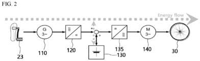
- FIG. 2 is a block diagram of the charging/discharging system for an electric bicycle according to an exemplary embodiment of the present disclosure
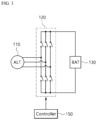
- FIG. 3 is a circuit diagram of the first inverter of FIG. 2 .
- the charging and discharging system of an electric bicycle is configured by including an alternator 110, a first inverter 120, a battery 130, a second inverter 135 and a motor 140.
- the electric bicycle is not limited thereto.
- the second inverter 135 may also be omitted.
- An electric bicycle requires electric power to obtain driving power and is provided with a battery 130 to supply such electric power.
- the alternator 110 is provided to charge the battery 130 while the electric bicycle is running.
- the alternator 110 generates an AC voltage by using rotational kinetic energy that is generated by rotational driving of the pedal 23 provided in the electric bicycle.
- the alternator 110 may be configured by including a driving shaft, a rotor and a stator, and the driving shaft is connected to the pedal 23 to rotate, and the rotor rotates by the driving shaft to generate current.
- the stator generates alternating current power by a rotating rotor.
- the first inverter 120 converts the AC voltage generated by the alternator 110 into a DC voltage.
- the first inverter 120 may be for converting AC power into DC power in the form of pulses having an arbitrary variable frequency through pulse width modulation (PWM), and it may include a plurality of, for example, six switches, and two of these switches may form a pair in series and be connected to phase terminals of the alternator 110, respectively.
- PWM pulse width modulation
- the three pairs of switches are field effect transistors (Metal Oxide Semiconductor Field-Effect Transistors; MOSFETs), and may be formed of N-MOSFEs, P-MOSFETs or other appropriate semiconductor switching elements.
- MOSFET Metal Oxide Semiconductor Field-Effect Transistors
- the MOSFET has a drain terminal, a gate terminal and a source terminal.
- the first inverter 120 charges the battery 130 by supplying the converted DC voltage to the battery 130.
- the controller 150 may control the first inverter 120 to convert an AC voltage to a DC voltage. Specifically, the controller 150 may convert an AC voltage into a DC voltage by controlling on-off duty ratios of a plurality of switches.
- the controller 150 may supply electric power generated by the alternator 110 to the motor 140 or charge the battery 130. That is, the DC voltage converted by the first inverter 120 is supplied to the battery 130 to charge the battery 130 or is supplied to the motor 140 to drive the motor 140 such that the wheel 30 can provide a rotational force.
- the second inverter 135 is a configuration for supplying an AC voltage to the motor 140, and it may convert the DC voltage charged in the battery 130 into an AC voltage and supply the same to the motor 140. Accordingly, the motor 140 may provide a rotational force to the wheel 30.
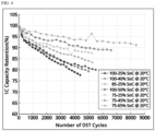
- FIG. 4 is a graph illustrating the life cycle of a battery 130 according to the range of charging amounts of the battery 130
- FIG. 5 is a graph illustrating the charging efficiency of a battery 1 30 according to the temperature of the battery 130 and the charging amount of the battery 130.
- the x-axis represents the number of charging/discharging cycles of the battery 130
- the y-axis represents the capacity retention rate of the battery 130.
- the capacity retention rate of the battery gradually decreases from 100%. In general, it is preferable to replace the battery when the capacity retention rate is 80% or lower. In addition, as the decrease rate of the capacity retention rate is smaller, the life cycle of the battery becomes longer.
- the temperature of the battery 130 is 20°C and the range of the charging amount (state of charge; SOC) of the battery is 75 to 65%, that is, when the battery 130 is discharged when the charging amount of the battery 130 is 75% and the battery 130 is charged when the charging amount thereof is 65%, it can be confirmed that it has the longest life cycle.
- the temperature of the battery 130 is 20°C and the range of the charging amount of the battery 130 is 100 to 25%, that is, when the battery 130 is discharged when the charging amount of the battery 130 is 100% and the battery 130 is charged when the charging amount thereof is 25%, it can be confirmed that it has the shortest life cycle.
- the life cycle of a battery 130 is the shortest when it is fully charged, then discharged, and then fully discharged, then charged, and it is the longest when it is charged and discharged while maintaining the charging amount of the battery 130 at a certain level or higher.
- the output voltage of the battery 130 is different according to the charging amount of the battery 130.
- the output voltage of the battery 130 may be classified into normal voltage, which is a normal range, high voltage that is higher than normal voltage by a certain level, low voltage that is lower than normal voltage by a certain level, over voltage that is higher than high voltage by a certain level, and under voltage that is lower than low voltage by a certain level.
- the controller 150 prohibits charging when the output voltage of the battery 130 is over voltage, and prohibits discharging when the output voltage of the battery 130 is under voltage. Further, in case of high voltage and low voltage, a warning is displayed.
- the absolute amounts of the above-mentioned certain levels vary between the actual implementations and particular use cases of the batteries 130. Thus, a skilled person will be aware of which absolute amounts are to be chosen for each of the certain levels.
- the x-axis represents the temperature of the battery 130
- the y-axis represents the charging efficiency of the battery 130.
- the charging efficiency is proportional to the temperature of the battery 130 in a range below the reference temperature (e.g., 20° C.), and is inversely proportional to the charging amount of the battery 130 in a range where the output voltage of the battery 130 is higher than the reference voltage (e.g., Low Voltage).
- the charging efficiency is 100% at SOC 50% and 20° C, and since battery life decreases if SOC is used too low, the low voltage is a voltage value corresponding to SOC 50%.
- the charging efficiency of the battery 130 increases as the temperature of the battery 130 increases when the temperature of the battery is in a range of 20°C or less.
- the charging efficiency of the battery 130 increases in the order of 90%, 70% and 50% as the charging amount of the battery 130 decreases in a range where the output voltage of the battery 130 is equal to or higher than the Low Voltage.
- the controller 150 may store the charging efficiency of the battery 130 according to the temperature of the battery 130 and the charging amount of the battery 130 in the form of a map, and may control charging of a plurality of batteries 130 by using the stored map.
- the electric bicycle of the present disclosure includes a plurality of batteries 130.
- the plurality of batteries 130 may be lithium-ion (Li-ion) batteries, but the present disclosure is not limited thereto.
- the plurality of batteries 130 may be charged with a DC voltage from the first inverter 120, and the motor 140 may receive electric power from at least one of the plurality of batteries 130 to provide a rotational force to the wheel 30.
- the controller 150 may selectively charge the plurality of batteries 130 according to the charging efficiency of the plurality of batteries 130. That is, the controller 150 may selectively charge a battery having the highest charging efficiency among the plurality of batteries 130.
- the controller 150 charges a battery 130 whose charging amount is less than or equal to a first reference charging amount (e.g., 25%) among the plurality of batteries 130 up to a second reference charging amount (e.g., 30%). Thereafter, the controller 150 may selectively charge the plurality of batteries 130 according to the charging efficiency.
- a first reference charging amount e.g., 25%
- a second reference charging amount e.g., 30%
- the controller 150 may compare the charging efficiencies of the plurality of batteries 130, select and charge a battery 130 having a higher charging efficiency among the plurality of batteries 130.
- the apparatus for controlling the charging of an electric bicycle may efficiently charge the plurality of batteries 130, thereby increasing the driving distance of the electric bicycle.
- the apparatus for controlling the charging of an electric bicycle compares the charging amounts of the plurality of batteries 130 with each other to charge, it is possible to charge and discharge by maintaining the charging amounts of the plurality of batteries 130 at a certain level or higher, and through this, the life cycle of the plurality of batteries 130 may be increased.
- FIG. 6 is a control block diagram of the apparatus for controlling the charging of an electric bicycle according to an exemplary embodiment of the present disclosure.
- the plurality of batteries 130 may include a first battery 131 and a second battery 132.
- the first battery 131 may be charged with a first charging amount
- the second battery 132 may be charged with a second charging amount that is higher than the first charging amount.
- the apparatus for controlling the charging of an electric bicycle may further include a first switch SW1 which is connected between the first battery 131 and the first inverter 120, and a second switch SW2 which is connected between the second battery 132 and the first inverter 120.
- the apparatus for controlling the charging of an electric bicycle may further include a first discharge switch which is connected between the first battery 131 and the second inverter 135, and a second discharge switch which is connected between the second battery 132 and the second inverter 135.
- the controller 150 may monitor the states of the first battery 131 and the second battery 132 before charging control. In this case, when the states of the first battery 131 and the second battery 132 are both normal, charge and discharge control may be performed.
- the controller 150 turns off both of the first and second switches SW1, SW2 and the first and second discharge switches when both of the first battery 131 and the second battery 132 have an error. In this case, the charging and discharging operations of the first battery 131 and the second battery 132 are not performed. In other words, the controller 150 may be configured to selectively turn off one or more of the switches SW1, SW2 based on an error occurred to a battery connected to the one or more of the switches SW1, SW2. Thus, charging of erroneous batteries can be prevented on a single battery level such that charging energy may be saved.
- the charging switch and discharging switch of the battery with the error are turned off. In this case, the control operation of selecting and charging the first battery 131 and the second battery 132 is not performed, and the charging and discharging operations are performed only by normal batteries.
- the controller 150 may control the on/off of the first switch SW1 and the second switch SW2 such that the first battery 131 and the second battery 132 may be selectively charged.
- the first switch SW1 when the first switch SW1 is turned on, the DC voltage supplied from the first inverter 120 charges the first battery 131, and when the second switch SW2 is turned on, the DC voltage supplied from the inverter 120 charges the second battery 132.
- the controller 150 may charge the first battery 131 up to a second reference charging amount (e.g., 30%) such that the output voltage of the first battery 131 is greater than or equal to the reference voltage.
- a first reference charging amount e.g. 25%
- a second reference charging amount e.g. 30%
- the controller 150 may selectively charge the first battery 131 and the second battery 132 according to the charging efficiency of the first battery 131 and the second battery 132.
- the controller 150 may charge the first battery 131 having a lower charging amount up to a second reference charging amount ( e.g ., 30%), and then charge the second battery 132 up to the second reference charging amount ( e.g ., 30%).
- the controller 150 may charge both of the first battery 131 and the second battery 132 up to the second reference amount of charge, and then selectively charge the first battery 131 and the second battery 132 according to the charging efficiency.
- the selective charging control method of the present disclosure will be described by taking a case in which the charging efficiency of the first battery 131 is higher than that of the second battery 132 as an example.
- the controller 150 may charge the first battery 131 by turning on the first switch SW1. As the first battery 131 is charged, the charging amount of the first battery 131 increases and eventually becomes greater than the charging amount of the second battery 132. In this case, the charging efficiency of the first battery 131 is lower than that of the second battery 132, and in this case, when the controller 150 immediately turns off the first switch SW1 and turns on the second switch SW2, a problem occurs in that switching power loss occurs due to frequent switch control.
- the controller 150 turns off the first switch SW1 when a difference in the charging efficiencies of the first battery 131 and the second battery 132 is greater than or equal to a reference value, and turns on the second switch SW2 to charge the second battery 132.
- the reference value may not be zero. In other words, the reference value provides the function of a buffer to prevent excessive switching control between the charging of the first and second batteries 131, 132.
- the controller 150 turns on the second switch SW2 to charge the second battery 132
- the controller may turn off the second switch SW2 and turn on the first switch SW1 to charge the first battery 131.
- the reference value may be a value that differs by at least 5% considering charging efficiency, component life, noise, etc.
- the apparatus for controlling the charging of an electric bicycle may reduce switching power loss through frequent switch control.
- the apparatus for controlling the charging of an electric bicycle may efficiently charge the first and second batteries 131, 132, thereby increasing the driving distance of the electric bicycle.
- the apparatus for controlling the charging of an electric bicycle compares the charging amounts of the first and second batteries 131, 132 with each other to charge, it is possible to charge and discharge while maintaining the charging amounts of the first and second batteries 131, 132 at least a certain level or higher, and through this, the life cycle of the first and second batteries 131, 132 may be increased.
- FIG. 7 is a flowchart of the method for controlling an apparatus for charging an electric bicycle according to an exemplary embodiment of the present disclosure
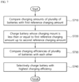
- FIG. 8 is a flowchart of the method of selectively charging a plurality of batteries according to an exemplary embodiment of the present disclosure.
- the method for controlling the apparatus for charging an electric bicycle is a method of converting an AC voltage generated by driving a pedal 23 into a DC voltage, and charging the DC voltage into a plurality of batteries 130.
- the charging amounts of the plurality of batteries 130 are compared with a first reference charging amount (e.g ., 25%) (S710).
- a battery whose charging amount is less than or equal to a first reference charging amount among the plurality of batteries 130 is charged up to a second reference charging amount (e.g ., 30 %) (S720).
- a reference voltage e.g., Low Voltage
- the step of selectively charging the plurality of batteries 130 compares the charging efficiencies of the plurality of batteries 130 while charging at least one of the plurality of batteries 130 to select and charge with a battery with a higher charging efficiency among the plurality of batteries 130.
- the method for controlling the charging of an electric bicycle may efficiently charge a plurality of batteries 130, thereby increasing the driving distance of the electric bicycle.
- the method for controlling the charging of an electric bicycle is a method of converting an AC voltage generated by driving a pedal 23 into a DC voltage, and charging the DC voltage into a first battery 131 and a second battery 132.
- the selective charging control method of the present disclosure will be described by taking a case in which the charging efficiency of the first battery 131 is higher than that of the second battery 132 as an example.
- the first battery 131 having a higher charging efficiency is charged before the second battery 132.
- the charging amount of the first battery 131 increases and eventually becomes greater than the charging amount of the second battery 132.
- the charging efficiency of the first battery 131 becomes lower than that of the second battery 132, and in this case, when the first and second switches SW1, SW2 are controlled immediately, a problem occurs in that switching power loss occurs due to frequent switch control.
- the present disclosure compares the charging efficiencies of the first battery 131 and the second battery 132 (S810).
- the first battery 131 having a higher charging efficiency is charged (S820).
- the method for controlling the charging an electric bicycle may reduce switching power loss through frequent switch control.
Landscapes
- Engineering & Computer Science (AREA)
- Mechanical Engineering (AREA)
- Transportation (AREA)
- Power Engineering (AREA)
- Life Sciences & Earth Sciences (AREA)
- Sustainable Development (AREA)
- Sustainable Energy (AREA)
- Chemical & Material Sciences (AREA)
- Combustion & Propulsion (AREA)
- Charge And Discharge Circuits For Batteries Or The Like (AREA)
Abstract
Description
- The present disclosure relates to an apparatus and method for controlling the charging of an electric bicycle, and more specifically to an apparatus and method for controlling the charging of an electric bicycle which are capable of efficiently charging a plurality of batteries and thereby increasing the driving distance of an electric bicycle.
- A bicycle is a means of transportation that is driven mainly by the rider's leg power. Recently, electric bicycles which are equipped with a battery and add a driving force for movement by adding a motor driven by the battery have been widely used.
- Such electric bicycles must be lightweight such that power required for driving can be minimized. To this end, the parts that are mounted on the electric bicycle must be as small as possible in size and weight such that there is no inconvenience in using the bicycle.
- In the case of electric bicycles, a battery is used, and the battery may be generally mounted on a frame or inside a tube constituting the frame. The capacity of the battery may increase as the size of the battery increases, but it cannot be increased indefinitely due to the total weight of the electric bicycle and the arrangement thereof in the frame. Therefore, when the battery is used, there is a problem in that the space for mounting on the frame is reduced.
- However, in order to meet the recent demand for increasing the driving distance of electric bicycles, electric bicycles are provided with a plurality of batteries.
- As the electric bicycle is provided with a plurality of batteries, the development of a control technique that is capable of efficiently charging the plurality of batteries is required.
- An object of the present disclosure is to provide an apparatus and method for controlling the charging of an electric bicycle which are capable of efficiently charging a plurality of batteries and thereby increasing the driving distance of an electric bicycle.
- In addition, another object of the present disclosure is to provide an apparatus and method for controlling the charging of an electric bicycle which are capable of charging and discharging a plurality of batteries while maintaining the charging amount of a plurality of batteries at a certain level or higher, thereby increasing the life cycle of a plurality of batteries.
- In addition, still another object of the present disclosure is to provide an apparatus and method for controlling the charging of an electric bicycle which are capable of reducing switching power loss through frequent switch control.
- The technical problems to be achieved in the present disclosure are not limited to the above-mentioned technical problems, and other technical problems that are not mentioned will be clearly understood by those skilled in the art to which the present disclosure pertains from the description below.
- The invention is set out in the appended set of claims. In order to solve the above-described problems, the present disclosure provides an apparatus for controlling the charging of an electric bicycle, including an alternator for generating an AC voltage by driving a pedal; an inverter for converting the AC voltage into a DC voltage; a plurality of batteries for charging the DC voltage; a motor which is supplied with electric power from at least one of the plurality of batteries to provide a rotational force to wheels; and a controller for selectively charging the plurality of batteries according to a charging efficiency of the plurality of batteries. Preferably, the controller is configured to selectively charge the plurality of batteries according to a charging efficiency of the plurality of batteries.
- Herein, the controller may (be configured to) selectively charge a battery having the highest charging efficiency among the plurality of batteries.
- In addition, the controller may (be configured to) charge a battery whose charging amount is less than or equal to a first reference charging amount among the plurality of batteries to a second reference charging amount, and then selectively charge the plurality of batteries according to the charging efficiency.
- In addition, the charging efficiency may be proportional to the temperature of the plurality of batteries in a range below the reference temperature, and may be inversely proportional to the charging amount of the plurality of batteries in a range where the output voltage of the plurality of batteries is greater than or equal to a reference voltage.
- In addition, the controller may (be configured to) compare the charging efficiencies of the plurality of batteries while charging at least one of the plurality of batteries, and select and charge a battery having a higher charging efficiency among the plurality of batteries.
- In addition, the plurality of batteries may include a first battery which is charged to a first charging amount; and a second battery which is charged to a second charging amount that is higher than the first charging amount.
- In addition, the apparatus for controlling the charging of an electric bicycle may further include a first switch which is connected between the first battery and the inverter; and a second switch which is connected between the second battery and the inverter.
- In addition, the controller may (be configured to) control on/off of the first and second switches to selectively charge the first battery and the second battery.
- In addition, after turning on the first switch, the controller may turn off the first switch and turn on the second switch based on a difference in the charging efficiencies of the first battery and the second battery, which is greater than or equal to a reference value. The controller may be configured to, after turning on the first switch, turn off the first switch and turn on the second switch based on a difference in the charging efficiencies of the first battery and the second battery, which is greater than or equal to a reference value.
- In addition, after turning on the second switch, the controller may turn off the second switch and turn on the first switch based on a difference in the charging efficiencies of the first battery and the second battery, which is greater than or equal to the reference value. The controller may be configured to, after turning on the second switch, turn off the second switch and turn on the first switch based on a difference in the charging efficiencies of the first battery and the second battery, which is greater than or equal to the reference value.
- In addition, the controller may (be configured to) charge the first battery to a second reference charging amount, and then charge the second battery to a second reference charging amount, based on the fact that both of the first and second charging amounts are less than or equal to a first reference charging amount.
- In addition, the controller may (be configured to) charge both of the first battery and the second battery to a second reference charging amount, and then selectively charge the first battery and the second battery according to the charging efficiency.
- In addition, the present disclosure provides a method for controlling the charging of an electric bicycle which converts an AC voltage generated by driving a pedal into a DC voltage and charges the DC voltage in a plurality of batteries, the method including the steps of comparing the charging amounts of the plurality of batteries with a first reference charging amount; charging a battery whose charging mount is less than or equal to a first reference charging amount among the plurality of batteries to a second reference charging amount; comparing the charging efficiencies of the plurality of batteries with each other; and selectively charging a battery with the highest charging efficiency among the plurality of batteries.
- Herein, the step of selectively charging a battery may be a step of comparing the charging efficiencies of the plurality of batteries while charging at least one of the plurality of batteries, selecting and charging a battery having a higher charging efficiency among the plurality of batteries.
- Furthermore, the electric bicycle may charge the DC voltage in a first battery and a second battery and the method may comprise the steps of comparing the charging efficiencies of the first battery and the second battery; charging the first battery with a higher charging efficiency among the first battery and the second battery; charging the second battery when a difference in the charging efficiencies is greater than or equal to a reference value after charging the first battery; and charging the first battery when a difference in the charging efficiencies is greater than or equal to the reference value after charging the second battery.
- In addition, the present disclosure provides a method for controlling the charging of an electric bicycle which converts an AC voltage generated by driving a pedal into a DC voltage and charges the DC voltage in a first battery and a second battery, the method including the steps of comparing the charging efficiencies of the first battery and the second battery; charging the first battery with a higher charging efficiency among the first battery and the second battery; charging the second battery when a difference in the charging efficiencies is greater than or equal to a reference value after charging the first battery; and charging the first battery when a difference in the charging efficiencies is greater than or equal to the reference value after charging the second battery.
- According to the present disclosure, it is possible to efficiently charge a plurality of batteries, thereby increasing the driving distance of an electric bicycle.
- In addition, according to the present disclosure, it is possible to charge and discharge a plurality of batteries while maintaining the charging amount of a plurality of batteries at a certain level or higher, and through this, the life cycle of a plurality of batteries can be increased.
- In addition, according to the present disclosure, it is possible to reduce switching power loss through frequent switch control.
- The effects of the present disclosure are not limited to those mentioned above, and other effects that are not mentioned will be clearly understood by those skilled in the art from the description below.
-
-
FIG. 1 is a block diagram of an electric bicycle to which the apparatus for controlling the charging of an electric bicycle according to an exemplary embodiment of the present disclosure is applied. -
FIG. 2 is a block diagram of the charging/discharging system for an electric bicycle according to an exemplary embodiment of the present disclosure. -
FIG. 3 is a circuit diagram of the first inverter ofFIG. 2 . -
FIG. 4 is a graph illustrating the life cycle of a battery according to the range of charging amounts of the battery. -
FIG. 5 is a graph illustrating the charging efficiency of a battery according to the temperature of the battery and the charging amount of the battery. -
FIG. 6 is a control block diagram of the apparatus for controlling the charging of an electric bicycle according to an exemplary embodiment of the present disclosure. -
FIG. 7 is a flowchart of the method for controlling an apparatus for charging an electric bicycle according to an exemplary embodiment of the present disclosure. -
FIG. 8 is a flowchart of the method of selectively charging a plurality of batteries according to an exemplary embodiment of the present disclosure. - Hereinafter, with reference to the accompanying drawings, the exemplary embodiments of the present disclosure will be described in detail so that those skilled in the art can easily practice the present disclosure. The present disclosure may be embodied in many different forms and is not limited to the exemplary embodiments set forth herein. In order to clearly describe the present disclosure in the drawings, parts that are irrelevant to the description are omitted, and the same reference numerals are assigned to the same or similar components throughout the specification.
- In the present specification, terms such as "include" or "have" are intended to designate that there is a feature, number, step, operation, component, part or combination thereof described in the specification, but it should be understood that it does not preclude the possibility of the presence or addition of one or more other features, numbers, steps, operations, components, parts or combinations thereof.
-
FIG. 1 is a block diagram of an electric bicycle to which the apparatus for controlling the charging of an electric bicycle according to an exemplary embodiment of the present disclosure is applied. - As illustrated in
FIG. 1 , the electric bicycle includes aframe 10 forming a skeleton. - A
front wheel 20 and ahandle part 21 are provided at the front of theframe 10, and a generator 22 is provided at the lower end of theframe 10. A pair ofpedals 23 are connected to both sides of the generator 22. Herein, the generator 22 is a configuration that changes the rotational force of thepedal 23 into electrical energy. - A
controller 150 for overall control of the electric bicycle is provided on an upper side of the generator 22 in theframe 10. - A
rear wheel 30 is rotatably mounted at the rear of theframe 10, and amotor 140 for driving the electric bicycle by rotating therear wheel 30 is mounted at the center of therear wheel 30. - Although the wheel is illustrated as being composed of two wheels in
FIG. 1 , the present disclosure is not limited thereto, and it may be composed of three or four wheels. In addition, although themotor 140 is illustrated as being mounted on therear wheel 30, it may be mounted on at least one of thefront wheel 20 and therear wheel 30. - In addition, the
motor 140 may include a transmission such that the occupant can change the rotational speed of therear wheel 30 by a manipulation device. Themotor 140 receives electric power from abattery 130 to be described below and rotates therear wheel 30 to provide a driving force to the electric bicycle. - A
battery 130 is provided in the inner space of theframe 10, and thebattery 130 is charged with electric energy generated by the generator 22. Although not illustrated inFIG. 1 , a battery management system (BMS) that performs overall management of thebattery 130 may be provided inside theframe 10. The battery management system is for overall management of thebattery 130, manages to use thebattery 130 under optimal conditions by monitoring the state of thebattery 130, and predicts the replacement time of thebattery 130 to perform a role of discovering problems associated with thebattery 130 in advance. - The electric bicycle equipped with the above-described configurations is in a drivable state while the
rear wheel 30 rotates as the occupant operates themotor 140 by manipulating the manipulation device. In this case, when thepedal 23 is rotated by foot, the rotational force of thepedal 23 is converted into electrical energy in thealternator 110, and the converted electrical energy is charged in thebattery 130 such that thebattery 130 can be continuously used. -
FIG. 2 is a block diagram of the charging/discharging system for an electric bicycle according to an exemplary embodiment of the present disclosure, andFIG. 3 is a circuit diagram of the first inverter ofFIG. 2 . - As illustrated in
FIG. 2 , the charging and discharging system of an electric bicycle according to an exemplary embodiment of the present disclosure is configured by including analternator 110, afirst inverter 120, abattery 130, asecond inverter 135 and amotor 140. However, the electric bicycle is not limited thereto. For example, thesecond inverter 135 may also be omitted. - An electric bicycle requires electric power to obtain driving power and is provided with a
battery 130 to supply such electric power. In addition, thealternator 110 is provided to charge thebattery 130 while the electric bicycle is running. - The
alternator 110 generates an AC voltage by using rotational kinetic energy that is generated by rotational driving of the pedal 23 provided in the electric bicycle. - Herein, the
alternator 110 may be configured by including a driving shaft, a rotor and a stator, and the driving shaft is connected to the pedal 23 to rotate, and the rotor rotates by the driving shaft to generate current. In addition, the stator generates alternating current power by a rotating rotor. - The
first inverter 120 converts the AC voltage generated by thealternator 110 into a DC voltage. - Referring to
FIG. 3 , thefirst inverter 120 may be for converting AC power into DC power in the form of pulses having an arbitrary variable frequency through pulse width modulation (PWM), and it may include a plurality of, for example, six switches, and two of these switches may form a pair in series and be connected to phase terminals of thealternator 110, respectively. - For example, the three pairs of switches are field effect transistors (Metal Oxide Semiconductor Field-Effect Transistors; MOSFETs), and may be formed of N-MOSFEs, P-MOSFETs or other appropriate semiconductor switching elements. Herein, the MOSFET has a drain terminal, a gate terminal and a source terminal.
- The
first inverter 120 charges thebattery 130 by supplying the converted DC voltage to thebattery 130. - The
controller 150 may control thefirst inverter 120 to convert an AC voltage to a DC voltage. Specifically, thecontroller 150 may convert an AC voltage into a DC voltage by controlling on-off duty ratios of a plurality of switches. - The
controller 150 may supply electric power generated by thealternator 110 to themotor 140 or charge thebattery 130. That is, the DC voltage converted by thefirst inverter 120 is supplied to thebattery 130 to charge thebattery 130 or is supplied to themotor 140 to drive themotor 140 such that thewheel 30 can provide a rotational force. - The
second inverter 135 is a configuration for supplying an AC voltage to themotor 140, and it may convert the DC voltage charged in thebattery 130 into an AC voltage and supply the same to themotor 140. Accordingly, themotor 140 may provide a rotational force to thewheel 30. -
FIG. 4 is a graph illustrating the life cycle of abattery 130 according to the range of charging amounts of thebattery 130, andFIG. 5 is a graph illustrating the charging efficiency of a battery 1 30 according to the temperature of thebattery 130 and the charging amount of thebattery 130. - In
FIG. 4 , the x-axis represents the number of charging/discharging cycles of thebattery 130, and the y-axis represents the capacity retention rate of thebattery 130. Herein, as the number of charging and discharging of thebattery 130 increases, the capacity retention rate of the battery gradually decreases from 100%. In general, it is preferable to replace the battery when the capacity retention rate is 80% or lower. In addition, as the decrease rate of the capacity retention rate is smaller, the life cycle of the battery becomes longer. - Referring to
FIG. 4 , when the temperature of thebattery 130 is 20°C and the range of the charging amount (state of charge; SOC) of the battery is 75 to 65%, that is, when thebattery 130 is discharged when the charging amount of thebattery 130 is 75% and thebattery 130 is charged when the charging amount thereof is 65%, it can be confirmed that it has the longest life cycle. - In addition, when the temperature of the
battery 130 is 20°C and the range of the charging amount of thebattery 130 is 100 to 25%, that is, when thebattery 130 is discharged when the charging amount of thebattery 130 is 100% and thebattery 130 is charged when the charging amount thereof is 25%, it can be confirmed that it has the shortest life cycle. - As described above, the life cycle of a
battery 130 is the shortest when it is fully charged, then discharged, and then fully discharged, then charged, and it is the longest when it is charged and discharged while maintaining the charging amount of thebattery 130 at a certain level or higher. - Generally, the output voltage of the
battery 130 is different according to the charging amount of thebattery 130. Specifically, the output voltage of thebattery 130 may be classified into normal voltage, which is a normal range, high voltage that is higher than normal voltage by a certain level, low voltage that is lower than normal voltage by a certain level, over voltage that is higher than high voltage by a certain level, and under voltage that is lower than low voltage by a certain level. Herein, thecontroller 150 prohibits charging when the output voltage of thebattery 130 is over voltage, and prohibits discharging when the output voltage of thebattery 130 is under voltage. Further, in case of high voltage and low voltage, a warning is displayed. The absolute amounts of the above-mentioned certain levels vary between the actual implementations and particular use cases of thebatteries 130. Thus, a skilled person will be aware of which absolute amounts are to be chosen for each of the certain levels. - In
FIG. 5 , the x-axis represents the temperature of thebattery 130, and the y-axis represents the charging efficiency of thebattery 130. Herein, the charging efficiency is proportional to the temperature of thebattery 130 in a range below the reference temperature (e.g., 20° C.), and is inversely proportional to the charging amount of thebattery 130 in a range where the output voltage of thebattery 130 is higher than the reference voltage (e.g., Low Voltage). As shown inFIG. 5 , the charging efficiency is 100% atSOC 50% and 20° C, and since battery life decreases if SOC is used too low, the low voltage is a voltage value corresponding toSOC 50%. - Referring to
FIG. 5 , it can be confirmed that the charging efficiency of thebattery 130 increases as the temperature of thebattery 130 increases when the temperature of the battery is in a range of 20°C or less. In addition, it can be confirmed that the charging efficiency of thebattery 130 increases in the order of 90%, 70% and 50% as the charging amount of thebattery 130 decreases in a range where the output voltage of thebattery 130 is equal to or higher than the Low Voltage. - The
controller 150 may store the charging efficiency of thebattery 130 according to the temperature of thebattery 130 and the charging amount of thebattery 130 in the form of a map, and may control charging of a plurality ofbatteries 130 by using the stored map. - In order to meet the demand for increasing the driving distance of an electric bicycle, the electric bicycle of the present disclosure includes a plurality of
batteries 130. Herein, the plurality ofbatteries 130 may be lithium-ion (Li-ion) batteries, but the present disclosure is not limited thereto. In addition, the plurality ofbatteries 130 may be charged with a DC voltage from thefirst inverter 120, and themotor 140 may receive electric power from at least one of the plurality ofbatteries 130 to provide a rotational force to thewheel 30. - In particular, the
controller 150 may selectively charge the plurality ofbatteries 130 according to the charging efficiency of the plurality ofbatteries 130. That is, thecontroller 150 may selectively charge a battery having the highest charging efficiency among the plurality ofbatteries 130. - In order to create a state in which the output voltage of the plurality of
batteries 130 is equal to or higher than the reference voltage (e.g., Low Voltage), thecontroller 150 charges abattery 130 whose charging amount is less than or equal to a first reference charging amount (e.g., 25%) among the plurality ofbatteries 130 up to a second reference charging amount (e.g., 30%). Thereafter, thecontroller 150 may selectively charge the plurality ofbatteries 130 according to the charging efficiency. - While charging at least one of the plurality of
batteries 130, thecontroller 150 may compare the charging efficiencies of the plurality ofbatteries 130, select and charge abattery 130 having a higher charging efficiency among the plurality ofbatteries 130. - Accordingly, the apparatus for controlling the charging of an electric bicycle according to an exemplary embodiment of the present disclosure may efficiently charge the plurality of
batteries 130, thereby increasing the driving distance of the electric bicycle. - In addition, since the apparatus for controlling the charging of an electric bicycle according to an exemplary embodiment of the present disclosure compares the charging amounts of the plurality of
batteries 130 with each other to charge, it is possible to charge and discharge by maintaining the charging amounts of the plurality ofbatteries 130 at a certain level or higher, and through this, the life cycle of the plurality ofbatteries 130 may be increased. -
FIG. 6 is a control block diagram of the apparatus for controlling the charging of an electric bicycle according to an exemplary embodiment of the present disclosure. - Referring to
FIG. 6 , the plurality ofbatteries 130 may include afirst battery 131 and asecond battery 132. Herein, thefirst battery 131 may be charged with a first charging amount, and thesecond battery 132 may be charged with a second charging amount that is higher than the first charging amount. - The apparatus for controlling the charging of an electric bicycle according to an exemplary embodiment of the present disclosure may further include a first switch SW1 which is connected between the
first battery 131 and thefirst inverter 120, and a second switch SW2 which is connected between thesecond battery 132 and thefirst inverter 120. - Although not illustrated in the drawings, the apparatus for controlling the charging of an electric bicycle according to an exemplary embodiment of the present disclosure may further include a first discharge switch which is connected between the
first battery 131 and thesecond inverter 135, and a second discharge switch which is connected between thesecond battery 132 and thesecond inverter 135. - The
controller 150 may monitor the states of thefirst battery 131 and thesecond battery 132 before charging control. In this case, when the states of thefirst battery 131 and thesecond battery 132 are both normal, charge and discharge control may be performed. - Unlike the above, the
controller 150 turns off both of the first and second switches SW1, SW2 and the first and second discharge switches when both of thefirst battery 131 and thesecond battery 132 have an error. In this case, the charging and discharging operations of thefirst battery 131 and thesecond battery 132 are not performed. In other words, thecontroller 150 may be configured to selectively turn off one or more of the switches SW1, SW2 based on an error occurred to a battery connected to the one or more of the switches SW1, SW2. Thus, charging of erroneous batteries can be prevented on a single battery level such that charging energy may be saved. - In addition, when any one of the
first battery 131 and thesecond battery 132 has an error, the charging switch and discharging switch of the battery with the error are turned off. In this case, the control operation of selecting and charging thefirst battery 131 and thesecond battery 132 is not performed, and the charging and discharging operations are performed only by normal batteries. - When the states of the
first battery 131 and thesecond battery 132 are both normal, thecontroller 150 may control the on/off of the first switch SW1 and the second switch SW2 such that thefirst battery 131 and thesecond battery 132 may be selectively charged. Herein, when the first switch SW1 is turned on, the DC voltage supplied from thefirst inverter 120 charges thefirst battery 131, and when the second switch SW2 is turned on, the DC voltage supplied from theinverter 120 charges thesecond battery 132. - Specifically, first of all, when the first charging amount of the
first battery 131 is less than or equal to a first reference charging amount (e.g., 25%), thecontroller 150 may charge thefirst battery 131 up to a second reference charging amount (e.g., 30%) such that the output voltage of thefirst battery 131 is greater than or equal to the reference voltage. - Thereafter, the
controller 150 may selectively charge thefirst battery 131 and thesecond battery 132 according to the charging efficiency of thefirst battery 131 and thesecond battery 132. - In addition, when both of the first charging amount of the
first battery 131 and the second charging amount of thesecond battery 132 are less than or equal to the first reference charging amount (e.g., 25%), thecontroller 150 may charge thefirst battery 131 having a lower charging amount up to a second reference charging amount (e.g., 30%), and then charge thesecond battery 132 up to the second reference charging amount (e.g., 30%). - Thereafter, the
controller 150 may charge both of thefirst battery 131 and thesecond battery 132 up to the second reference amount of charge, and then selectively charge thefirst battery 131 and thesecond battery 132 according to the charging efficiency. - Hereinafter, the selective charging control method of the present disclosure will be described by taking a case in which the charging efficiency of the
first battery 131 is higher than that of thesecond battery 132 as an example. - The
controller 150 may charge thefirst battery 131 by turning on the first switch SW1. As thefirst battery 131 is charged, the charging amount of thefirst battery 131 increases and eventually becomes greater than the charging amount of thesecond battery 132. In this case, the charging efficiency of thefirst battery 131 is lower than that of thesecond battery 132, and in this case, when thecontroller 150 immediately turns off the first switch SW1 and turns on the second switch SW2, a problem occurs in that switching power loss occurs due to frequent switch control. - In order to solve this problem, the
controller 150 turns off the first switch SW1 when a difference in the charging efficiencies of thefirst battery 131 and thesecond battery 132 is greater than or equal to a reference value, and turns on the second switch SW2 to charge thesecond battery 132. The reference value may not be zero. In other words, the reference value provides the function of a buffer to prevent excessive switching control between the charging of the first andsecond batteries - Thereafter, while the
controller 150 turns on the second switch SW2 to charge thesecond battery 132, when a difference in the charging efficiencies of thefirst battery 131 and thesecond battery 132 is greater than or equal to the reference value, the controller may turn off the second switch SW2 and turn on the first switch SW1 to charge thefirst battery 131. The reference value may be a value that differs by at least 5% considering charging efficiency, component life, noise, etc. - Through this, the apparatus for controlling the charging of an electric bicycle according to an exemplary embodiment of the present disclosure may reduce switching power loss through frequent switch control.
- As such, the apparatus for controlling the charging of an electric bicycle according to an exemplary embodiment of the present disclosure may efficiently charge the first and
second batteries - In addition, since the apparatus for controlling the charging of an electric bicycle according to an exemplary embodiment of the present disclosure compares the charging amounts of the first and
second batteries second batteries second batteries -
FIG. 7 is a flowchart of the method for controlling an apparatus for charging an electric bicycle according to an exemplary embodiment of the present disclosure, andFIG. 8 is a flowchart of the method of selectively charging a plurality of batteries according to an exemplary embodiment of the present disclosure. - Referring to
FIG. 7 , the method for controlling the apparatus for charging an electric bicycle according to an exemplary embodiment of the present disclosure is a method of converting an AC voltage generated by driving apedal 23 into a DC voltage, and charging the DC voltage into a plurality ofbatteries 130. - Specifically, first of all, the charging amounts of the plurality of
batteries 130 are compared with a first reference charging amount (e.g., 25%) (S710). - Next, in order to create a state in which the output voltages of the plurality of
batteries 130 are equal to or higher than a reference voltage (e.g., Low Voltage), a battery whose charging amount is less than or equal to a first reference charging amount among the plurality ofbatteries 130 is charged up to a second reference charging amount (e.g., 30 %) (S720). - Next, the charging efficiencies of the plurality of
batteries 130 are compared with each other (S730). - Next, a battery having the highest charging efficiency among the plurality of
batteries 130 is selectively charged (S740). - Herein, the step of selectively charging the plurality of
batteries 130 compares the charging efficiencies of the plurality ofbatteries 130 while charging at least one of the plurality ofbatteries 130 to select and charge with a battery with a higher charging efficiency among the plurality ofbatteries 130. - Accordingly, the method for controlling the charging of an electric bicycle according to an exemplary embodiment of the present disclosure may efficiently charge a plurality of
batteries 130, thereby increasing the driving distance of the electric bicycle. - Further, in the method for controlling the charging of an electric bicycle according to an exemplary embodiment of the present disclosure, since charging is performed while comparing the charging amounts of the plurality of
batteries 130 with each other, it is possible to charge and discharge while maintaining the charging amounts of the plurality ofbatteries 130 at a certain level or higher, and through this, the life cycle of the plurality ofbatteries 130 may be increased. - Referring to
FIG. 8 , the method for controlling the charging of an electric bicycle according to an exemplary embodiment of the present disclosure is a method of converting an AC voltage generated by driving apedal 23 into a DC voltage, and charging the DC voltage into afirst battery 131 and asecond battery 132. - Hereinafter, the selective charging control method of the present disclosure will be described by taking a case in which the charging efficiency of the
first battery 131 is higher than that of thesecond battery 132 as an example. - The
first battery 131 having a higher charging efficiency is charged before thesecond battery 132. As thefirst battery 131 is charged, the charging amount of thefirst battery 131 increases and eventually becomes greater than the charging amount of thesecond battery 132. In this case, the charging efficiency of thefirst battery 131 becomes lower than that of thesecond battery 132, and in this case, when the first and second switches SW1, SW2 are controlled immediately, a problem occurs in that switching power loss occurs due to frequent switch control. - In order to solve this problem, first of all, the present disclosure compares the charging efficiencies of the
first battery 131 and the second battery 132 (S810). - Next, among the
first battery 131 and thesecond battery 132, thefirst battery 131 having a higher charging efficiency is charged (S820). - Next, when a difference in the charging efficiencies of the
first battery 131 and thesecond battery 132 is greater than or equal to a reference value after charging thefirst battery 131, the second battery is charged (S830). - Next, when a difference in the charging efficiencies of the
first battery 131 and thesecond battery 132 is greater than equal to a reference value after charging thesecond battery 132, thefirst battery 131 is charged (S840). - Through this, the method for controlling the charging an electric bicycle according to an exemplary embodiment of the present disclosure may reduce switching power loss through frequent switch control.
- Although an exemplary embodiment of the present disclosure has been described above, the present disclosure is not limited to the exemplary embodiments presented herein, and those skilled in the art who understand the present disclosure may easily propose other exemplary embodiments by modifying, changing, deleting or adding components, but this will also fall within the scope of the present disclosure which is defined in the appended set of claims.
Claims (15)
- An apparatus for controlling the charging of an electric bicycle, comprising:an alternator (110) for generating an AC voltage by driving a pedal (23);an inverter (120) for converting the AC voltage into a DC voltage;a plurality of batteries (130) for charging the DC voltage;a motor (140) which is supplied with electric power from at least one of the plurality of batteries (130) to provide a rotational force to wheels (20, 30); anda controller (150) configured to selectively charge the plurality of batteries (130) according to a charging efficiency of the plurality of batteries (150).
- The apparatus of claim 1, wherein the controller (150) is configured to selectively charge a battery (130) having the highest charging efficiency among the plurality of batteries (130).
- The apparatus of claim 1 or 2, wherein the controller (150) is configured to charge a battery (130) whose charging amount is less than or equal to a first reference charging amount among the plurality of batteries (130) to a second reference charging amount, and to then selectively charge the plurality of batteries (130) according to the charging efficiency.
- The apparatus of any one of the preceding claims, wherein the charging efficiency is proportional to the temperature of the plurality of batteries (130) in a range below the reference temperature, and is inversely proportional to the charging amount of the plurality of batteries (130) in a range where the output voltage of the plurality of batteries (130) is greater than or equal to a reference voltage.
- The apparatus of any one of the preceding claims, wherein the controller (150) is configured to compare the charging efficiencies of the plurality of batteries (130) while charging at least one of the plurality of batteries (130), and to select and charge a battery (130) having a higher charging efficiency among the plurality of batteries (130).
- The apparatus of any one of the preceding claims, wherein the plurality of batteries (130) comprise:a first battery (131) which is charged to a first charging amount; anda second battery (132) which is charged to a second charging amount that is higher than the first charging amount.
- The apparatus of claim 6, further comprising:a first switch (SW1) which is connected between the first battery (131) and the inverter (120); anda second switch (SW2) which is connected between the second battery (132) and the inverter (120).
- The apparatus of claim 7, wherein the controller (150) is configured to control on/off of the first and second switches (SW1, SW2) to selectively charge the first battery (131) and the second battery (132).
- The apparatus of claim 7 or 8, wherein the controller (150) is configured to, after turning on the first switch (SW1), turn off the first switch (131) and to turn on the second switch (SW2) based on a difference in the charging efficiencies of the first battery (131) and the second battery (132), which is greater than or equal to a reference value.
- The apparatus of claim 9, wherein the controller (150) is configured to, after turning on the second switch (SW2), turn off the second switch (SW2) and to turn on the first switch (SW1) based on a difference in the charging efficiencies of the first battery (131) and the second battery (132), which is greater than or equal to the reference value.
- The apparatus of any one of the claims 7 to 10, wherein the controller (150) is configured to charge the first battery (131) to a second reference charging amount, and to then charge the second battery (132) to the second reference charging amount, based on the fact that both of the first and second charging amounts are less than or equal to a first reference charging amount.
- The apparatus of claim 11, wherein the controller (150) is configured to charge both of the first battery (131) and the second battery (132) to a second reference charging amount, and to then selectively charge the first battery (131) and the second battery (132) according to the charging efficiency.
- A method for controlling the charging of an electric bicycle which converts an AC voltage generated by driving a pedal (23) into a DC voltage and charges the DC voltage in a plurality of batteries (130), the method comprising the steps of:Comparing (S710) the charging amounts of the plurality of batteries (130) with a first reference charging amount;charging (S720) a battery (130) whose charging mount is less than or equal to a first reference charging amount among the plurality of batteries (130) to a second reference charging amount;comparing (S730) the charging efficiencies of the plurality of batteries (130) with each other; andselectively charging (S740) a battery (130) with the highest charging efficiency among the plurality of batteries (130).
- The method of claim 13, wherein the step of selectively charging (S740) a battery (130) is a step of comparing the charging efficiencies of the plurality of batteries (130) while charging at least one of the plurality of batteries (130), selecting and charging a battery (130) having a higher charging efficiency among the plurality of batteries (130).
- The of claim 13 or 14, wherein the electric bicycle charges the DC voltage in a first battery (131) and a second battery (132), the method comprising the steps of:comparing (S810) the charging efficiencies of the first battery (131) and the second battery (132);charging (S820) the first battery (131) with a higher charging efficiency among the first battery (131) and the second battery (132);charging (S830) the second battery (132) when a difference in the charging efficiencies is greater than or equal to a reference value after charging the first battery (131); andcharging (S840) the first battery (131) when a difference in the charging efficiencies is greater than or equal to the reference value after charging the second battery (132).
Applications Claiming Priority (1)
| Application Number | Priority Date | Filing Date | Title |
|---|---|---|---|
| KR1020230022022A KR102749782B1 (en) | 2023-02-20 | 2023-02-20 | Apparatus and method for charging control of electric bicycle |
Publications (2)
| Publication Number | Publication Date |
|---|---|
| EP4417457A1 true EP4417457A1 (en) | 2024-08-21 |
| EP4417457B1 EP4417457B1 (en) | 2025-12-03 |
Family
ID=88511502
Family Applications (1)
| Application Number | Title | Priority Date | Filing Date |
|---|---|---|---|
| EP23205152.4A Active EP4417457B1 (en) | 2023-02-20 | 2023-10-23 | Apparatus and method for charging control of electric bicycle |
Country Status (2)
| Country | Link |
|---|---|
| EP (1) | EP4417457B1 (en) |
| KR (1) | KR102749782B1 (en) |
Citations (3)
| Publication number | Priority date | Publication date | Assignee | Title |
|---|---|---|---|---|
| US20120202649A1 (en) * | 2011-02-07 | 2012-08-09 | Clarkson University | Pedal generator electric bicycle |
| WO2012153877A1 (en) * | 2011-05-09 | 2012-11-15 | (주) 에프엑스기어 | Power supply apparatus for an electric bicycle |
| CN106183857A (en) * | 2016-08-02 | 2016-12-07 | 威马中德汽车科技成都有限公司 | A kind of dual battery system double cell cycle-index control method and system |
Family Cites Families (2)
| Publication number | Priority date | Publication date | Assignee | Title |
|---|---|---|---|---|
| JP2004222473A (en) * | 2003-01-17 | 2004-08-05 | Toyota Motor Corp | Vehicle power supply system and charging method |
| KR102777211B1 (en) * | 2021-07-13 | 2025-03-07 | 에이치엘만도 주식회사 | Apparatus and method for power control of electric bicycle |
-
2023
- 2023-02-20 KR KR1020230022022A patent/KR102749782B1/en active Active
- 2023-10-23 EP EP23205152.4A patent/EP4417457B1/en active Active
Patent Citations (3)
| Publication number | Priority date | Publication date | Assignee | Title |
|---|---|---|---|---|
| US20120202649A1 (en) * | 2011-02-07 | 2012-08-09 | Clarkson University | Pedal generator electric bicycle |
| WO2012153877A1 (en) * | 2011-05-09 | 2012-11-15 | (주) 에프엑스기어 | Power supply apparatus for an electric bicycle |
| CN106183857A (en) * | 2016-08-02 | 2016-12-07 | 威马中德汽车科技成都有限公司 | A kind of dual battery system double cell cycle-index control method and system |
Also Published As
| Publication number | Publication date |
|---|---|
| KR20240129331A (en) | 2024-08-27 |
| KR102749782B1 (en) | 2025-01-03 |
| EP4417457B1 (en) | 2025-12-03 |
Similar Documents
| Publication | Publication Date | Title |
|---|---|---|
| US10836264B2 (en) | Drive system | |
| US8039987B2 (en) | Power source device and vehicle with power source device | |
| KR101822656B1 (en) | Electric device for driving mechanical equipment and associated method | |
| US10875418B2 (en) | Charge control apparatus and system | |
| US9793722B2 (en) | Power source apparatus for vehicle | |
| JP6404221B2 (en) | Structure for modulating the voltage of a battery and its active balancing | |
| CN112769373B (en) | Electric propulsion system and method for optimizing driving operation of an electric propulsion system | |
| JP6494749B2 (en) | Electric drive system and method for driving electric motor of electric vehicle | |
| US20030067278A1 (en) | Drive apparatus, control method for the drive apparatus, storage medium storing a program controlling the drive apparatus, and power output apparatus | |
| JP2003092805A (en) | Power supply unit for hybrid car | |
| JP2006067683A (en) | Power storage device | |
| US6777912B1 (en) | Power source system for driving vehicle | |
| KR101835742B1 (en) | Dual Battery Package and Operating Method of the Same | |
| US9490710B2 (en) | Power supply device for supplying power to a load by combining a secondary battery and a capacitor | |
| US10960769B2 (en) | Onboard charging apparatus | |
| JP3612572B2 (en) | Motor drive power supply | |
| EP4417457B1 (en) | Apparatus and method for charging control of electric bicycle | |
| JP3645881B2 (en) | Bicycle dynamo charger | |
| JP6034734B2 (en) | Power system | |
| JP4139290B2 (en) | Electric vehicle power supply | |
| JP6055703B2 (en) | Power system | |
| KR101686864B1 (en) | Dual battery package | |
| CN120621089A (en) | Traction battery pack charging and discharging operations | |
| KR20200095828A (en) | Power converting apparatus of electric bicycle | |
| JP2018019504A (en) | Power system for electric vehicles |
Legal Events
| Date | Code | Title | Description |
|---|---|---|---|
| PUAI | Public reference made under article 153(3) epc to a published international application that has entered the european phase |
Free format text: ORIGINAL CODE: 0009012 |
|
| STAA | Information on the status of an ep patent application or granted ep patent |
Free format text: STATUS: REQUEST FOR EXAMINATION WAS MADE |
|
| 17P | Request for examination filed |
Effective date: 20231023 |
|
| AK | Designated contracting states |
Kind code of ref document: A1 Designated state(s): AL AT BE BG CH CY CZ DE DK EE ES FI FR GB GR HR HU IE IS IT LI LT LU LV MC ME MK MT NL NO PL PT RO RS SE SI SK SM TR |
|
| GRAP | Despatch of communication of intention to grant a patent |
Free format text: ORIGINAL CODE: EPIDOSNIGR1 |
|
| STAA | Information on the status of an ep patent application or granted ep patent |
Free format text: STATUS: GRANT OF PATENT IS INTENDED |
|
| INTG | Intention to grant announced |
Effective date: 20250519 |
|
| GRAS | Grant fee paid |
Free format text: ORIGINAL CODE: EPIDOSNIGR3 |
|
| GRAA | (expected) grant |
Free format text: ORIGINAL CODE: 0009210 |
|
| STAA | Information on the status of an ep patent application or granted ep patent |
Free format text: STATUS: THE PATENT HAS BEEN GRANTED |
|
| AK | Designated contracting states |
Kind code of ref document: B1 Designated state(s): AL AT BE BG CH CY CZ DE DK EE ES FI FR GB GR HR HU IE IS IT LI LT LU LV MC ME MK MT NL NO PL PT RO RS SE SI SK SM TR |
|
| REG | Reference to a national code |
Ref country code: CH Ref legal event code: F10 Free format text: ST27 STATUS EVENT CODE: U-0-0-F10-F00 (AS PROVIDED BY THE NATIONAL OFFICE) Effective date: 20251203 Ref country code: GB Ref legal event code: FG4D |
|
| REG | Reference to a national code |
Ref country code: DE Ref legal event code: R096 Ref document number: 602023009249 Country of ref document: DE |
|
| REG | Reference to a national code |
Ref country code: IE Ref legal event code: FG4D |
|
| REG | Reference to a national code |
Ref country code: NL Ref legal event code: MP Effective date: 20251203 |
|
| PG25 | Lapsed in a contracting state [announced via postgrant information from national office to epo] |
Ref country code: ES Free format text: LAPSE BECAUSE OF FAILURE TO SUBMIT A TRANSLATION OF THE DESCRIPTION OR TO PAY THE FEE WITHIN THE PRESCRIBED TIME-LIMIT Effective date: 20251203 |
|
| REG | Reference to a national code |
Ref country code: LT Ref legal event code: MG9D |
|
| PG25 | Lapsed in a contracting state [announced via postgrant information from national office to epo] |
Ref country code: NO Free format text: LAPSE BECAUSE OF FAILURE TO SUBMIT A TRANSLATION OF THE DESCRIPTION OR TO PAY THE FEE WITHIN THE PRESCRIBED TIME-LIMIT Effective date: 20260303 |
|
| PG25 | Lapsed in a contracting state [announced via postgrant information from national office to epo] |
Ref country code: HR Free format text: LAPSE BECAUSE OF FAILURE TO SUBMIT A TRANSLATION OF THE DESCRIPTION OR TO PAY THE FEE WITHIN THE PRESCRIBED TIME-LIMIT Effective date: 20251203 Ref country code: FI Free format text: LAPSE BECAUSE OF FAILURE TO SUBMIT A TRANSLATION OF THE DESCRIPTION OR TO PAY THE FEE WITHIN THE PRESCRIBED TIME-LIMIT Effective date: 20251203 |
|
| PG25 | Lapsed in a contracting state [announced via postgrant information from national office to epo] |
Ref country code: RS Free format text: LAPSE BECAUSE OF FAILURE TO SUBMIT A TRANSLATION OF THE DESCRIPTION OR TO PAY THE FEE WITHIN THE PRESCRIBED TIME-LIMIT Effective date: 20260303 |
|
| PG25 | Lapsed in a contracting state [announced via postgrant information from national office to epo] |
Ref country code: PL Free format text: LAPSE BECAUSE OF FAILURE TO SUBMIT A TRANSLATION OF THE DESCRIPTION OR TO PAY THE FEE WITHIN THE PRESCRIBED TIME-LIMIT Effective date: 20251203 |
|
| PG25 | Lapsed in a contracting state [announced via postgrant information from national office to epo] |
Ref country code: LV Free format text: LAPSE BECAUSE OF FAILURE TO SUBMIT A TRANSLATION OF THE DESCRIPTION OR TO PAY THE FEE WITHIN THE PRESCRIBED TIME-LIMIT Effective date: 20251203 |
|
| PG25 | Lapsed in a contracting state [announced via postgrant information from national office to epo] |
Ref country code: BG Free format text: LAPSE BECAUSE OF FAILURE TO SUBMIT A TRANSLATION OF THE DESCRIPTION OR TO PAY THE FEE WITHIN THE PRESCRIBED TIME-LIMIT Effective date: 20251203 |