EP4417432A2 - Method for quality inspection of nozzles of an ink-jet print module - Google Patents
Method for quality inspection of nozzles of an ink-jet print module Download PDFInfo
- Publication number
- EP4417432A2 EP4417432A2 EP24158333.5A EP24158333A EP4417432A2 EP 4417432 A2 EP4417432 A2 EP 4417432A2 EP 24158333 A EP24158333 A EP 24158333A EP 4417432 A2 EP4417432 A2 EP 4417432A2
- Authority
- EP
- European Patent Office
- Prior art keywords
- test pattern
- nozzles
- decor layer
- test
- paperboard web
- Prior art date
- Legal status (The legal status is an assumption and is not a legal conclusion. Google has not performed a legal analysis and makes no representation as to the accuracy of the status listed.)
- Pending
Links
Images


Classifications
-
- B—PERFORMING OPERATIONS; TRANSPORTING
- B41—PRINTING; LINING MACHINES; TYPEWRITERS; STAMPS
- B41J—TYPEWRITERS; SELECTIVE PRINTING MECHANISMS, i.e. MECHANISMS PRINTING OTHERWISE THAN FROM A FORME; CORRECTION OF TYPOGRAPHICAL ERRORS
- B41J2/00—Typewriters or selective printing mechanisms characterised by the printing or marking process for which they are designed
- B41J2/005—Typewriters or selective printing mechanisms characterised by the printing or marking process for which they are designed characterised by bringing liquid or particles selectively into contact with a printing material
- B41J2/01—Ink jet
- B41J2/21—Ink jet for multi-colour printing
- B41J2/2132—Print quality control characterised by dot disposition, e.g. for reducing white stripes or banding
- B41J2/2146—Print quality control characterised by dot disposition, e.g. for reducing white stripes or banding for line print heads
-
- B—PERFORMING OPERATIONS; TRANSPORTING
- B41—PRINTING; LINING MACHINES; TYPEWRITERS; STAMPS
- B41J—TYPEWRITERS; SELECTIVE PRINTING MECHANISMS, i.e. MECHANISMS PRINTING OTHERWISE THAN FROM A FORME; CORRECTION OF TYPOGRAPHICAL ERRORS
- B41J2/00—Typewriters or selective printing mechanisms characterised by the printing or marking process for which they are designed
- B41J2/005—Typewriters or selective printing mechanisms characterised by the printing or marking process for which they are designed characterised by bringing liquid or particles selectively into contact with a printing material
- B41J2/01—Ink jet
- B41J2/21—Ink jet for multi-colour printing
- B41J2/2132—Print quality control characterised by dot disposition, e.g. for reducing white stripes or banding
- B41J2/2142—Detection of malfunctioning nozzles
-
- B—PERFORMING OPERATIONS; TRANSPORTING
- B65—CONVEYING; PACKING; STORING; HANDLING THIN OR FILAMENTARY MATERIAL
- B65B—MACHINES, APPARATUS OR DEVICES FOR, OR METHODS OF, PACKAGING ARTICLES OR MATERIALS; UNPACKING
- B65B61/00—Auxiliary devices, not otherwise provided for, for operating on sheets, blanks, webs, binding material, containers or packages
- B65B61/26—Auxiliary devices, not otherwise provided for, for operating on sheets, blanks, webs, binding material, containers or packages for marking or coding completed packages
-
- B—PERFORMING OPERATIONS; TRANSPORTING
- B41—PRINTING; LINING MACHINES; TYPEWRITERS; STAMPS
- B41J—TYPEWRITERS; SELECTIVE PRINTING MECHANISMS, i.e. MECHANISMS PRINTING OTHERWISE THAN FROM A FORME; CORRECTION OF TYPOGRAPHICAL ERRORS
- B41J25/00—Actions or mechanisms not otherwise provided for
- B41J2025/008—Actions or mechanisms not otherwise provided for comprising a plurality of print heads placed around a drum
Definitions
- the invention relates to a method for quality inspection of nozzles of an ink-jet print module, a converting unit, a laminated packaging material, and a package folded from a laminated packaging material.
- Packaging containers of the single use disposable type for liquid foods are often produced from a laminated packaging material.
- the laminated packaging material is produced as a continuous web, which is either used in a roll-fed package forming and filling machine or cut into separate blanks for use in a blank-fed package forming and filling machine.
- the laminated packaging material is produced using a converting procedure in which multiple materials are joined and processed to form the ready-to-use web of laminated packaging material.
- a paperboard web, forming the core layer of the laminated packaging material may be digitally printed on the outside (i.e. the side intended as the exterior side of the laminated packaging material) for example by ink-jet printing.
- Print defects may arise from misfiring, non-jetting, clogged or blocked nozzles, crooked or in any way defective nozzles of the print heads. It is important to be able to detect such defects and accurately associate them with the specific faulty nozzle, single nozzle or multiple nozzles, in order to ensure a desired quality of the packaging material web and optimum print quality performance of the digital printing process.
- US2009189928A1 discloses an image forming apparatus that forms images with a recording unit by ejecting inks, as coloring material, and treatment liquid from nozzles onto a recording medium, and that prints detection images for each color of ink so as to overlap each other.
- the recording unit prints a nozzle-check pattern.
- the nozzle-check patterns are printed between one image region and another image region formed with images instructed for image forming by a user, a specific example thereof being printing in a non-image region provided between each page.
- the size (width W) of the non-image region is determined based on the size of the nozzle-check patterns.
- US2017021612A1 discloses a method of testing a print head, a printing method, a device for testing a print head, and a printer which are capable of accurately detecting an abnormality of a recording element in a short period of time.
- the print head prints a predetermined test chart, and the test chart is tested whether there is an abnormal nozzle based on a result of the output, or not.
- the test chart is printed in a margin region of the paper to perform the test of the print head during the execution of the printing job. Therefore, printing of an image on the paper is performed with a margin.
- test charts are printed in margin regions formed between respective images.
- a method for quality inspection of nozzles of an ink-jet print module comprises forwarding a paperboard web continuously at a substantially constant speed in a machine direction; printing a decor layer on the paperboard web using the ink-jet print module; and printing a test pattern comprising a test element on the paperboard web by activating a plurality of the nozzles, which are intended to be inspected, and the test element having a fixed position in relation to the decor layer.
- the test pattern is indicative of the quality of each nozzle of the plurality of nozzles.
- the quality of the nozzles of the ink-jet print module used in printing decor on paperboard webs to form packaging materials can be easily tested due to the fixed positioning of the test pattern in relation to the decor layer, which gives a quick and accurate indication of whether a particular nozzle is faulty or not.
- a converting unit configured to continuously manufacture a packaging material web.
- the converting unit comprises a feeding unit configured to continuously forward a paperboard web at a substantially constant speed in a machine direction, an ink-jet print module comprising a plurality of print heads with a plurality of nozzles and being configured to print a decor layer and a test pattern comprising a test element on the paperboard web.
- the test pattern is printed by activating the plurality of nozzles, such that the test pattern extends or is arranged at a fixed position in relation to the decor layer.
- the test pattern is indicative of the quality of each nozzle of the plurality of nozzles.
- a laminated packaging material comprises a paperboard web having a decor layer and a test pattern comprising a test element printed thereon.
- the test pattern extends at least partially across the decor layer and has a fixed position in relation to the decor layer.
- a package folded from a laminated packaging material according to the above is provided.
- the test pattern is at least partly hidden in the folded package.
- each element of the test pattern is associated with a specific nozzle, which is detectable by inspection. This provides a quick and reliable way of identifying a nozzle which is faulty and in need of service.
- Detecting print defects is significantly easier if the test elements are fixed in relation to the decor layer. Extension of the test pattern with its test elements across the web enables error detection up to the full paperboard web width which reduces the inspection system complexity. Moreover, the quality inspection method is capable of detecting a single faulty digital printing nozzle, or even two neighboring nozzles, while production is running.
- a package such as a liquid food or beverage container, is formed by folding blanks of a laminated packaging material.
- the packaging material is typically manufactured in a manufacturing unit, such as a converting unit.
- a decor layer is printed onto a substrate which, after a series of process steps, eventually forms part of the laminated packaging material.
- the substrate is referred to as a paperboard material.
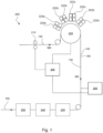
- a converting unit 200 configured to manufacture a laminated packaging material web 100 is illustrated schematically.
- the converting unit 200 includes at least one feeding unit 210, here illustrated as two feeding rolls.
- the feeding unit(s) 210 is configured to continuously forward a paperboard web 130 at a substantially constant speed, preferably in the machine direction MD as indicated by the arrow markings in Fig. 1 , for example on 200 m/min or faster, particularly 230-280 m/min, more particularly 240-275 m/min, most particularly 270-275 m/min.
- the converting unit 200 further comprises an ink-jet print module 220 comprising a plurality of print heads 222a-d, each print head 222a-d having a plurality of nozzles.
- the plurality of nozzles of the ink-jet print module 220 extends across the paperboard web 130 in a transverse direction which is perpendicular to the machine direction MD.
- the ink-jet print module 220 is configured to print a decor layer 140, as well as a test pattern 150 comprising at least one test element (not shown), on the paperboard web 130. For instance, there may be one printed test pattern per print head 222a-d across the printed substrate, which in this case is the paperboard web 130. This reduces the challenges faced by the in-line detection system to find the potentially misfiring, crooked or in any way faulty nozzles, and makes nozzle inspection possible without complex image recognition system in place.
- the ink-jet print module 220 is illustrated as a support cylinder and a plurality of print heads 222a-d for cyan C, magenta M, yellow Y and black K. It should be noted that the exact configuration of the ink-jet print module 220 may be different depending on the particular application; for example, the ink-jet printer 220 may comprise multiple print heads 222a-d arranged in the machine direction and/or the transverse direction in order to cover the entire width of the paperboard web 130. Each print head 222a-d may be configured to print a unique color. Alternately, as shown in Fig. 1 , there are several print heads 222a-d for each unique color. Thus, the printed test pattern 150 may comprise a test element for each unique color and/or for each print head 222a-d.
- Test pattern 150 including test elements
- Printing of the test pattern 150, including test elements, onto the paperboard web 130 is performed by activating the plurality of nozzles of the ink-jet print module 220, such that the test pattern 150 extends at a fixed position in relation to the decor layer 140.
- the test pattern 150 is indicative of the quality of each nozzle of the plurality of nozzles.
- each nozzle of the plurality of nozzles are activated simultaneously, i.e. at the same time.
- the fixed position of the test pattern 150 in relation to the decor layer 140 is to ensure reproducibility as well as traceability of the test pattern 150.
- the test pattern 150 which includes a test element, may extend in a direction transverse to the machine direction MD, or in parallel, or in any angle of choice with respect to the machine direction MD.
- the test element may for instance be a design element, such as a continuous design element, for instance a continues line formed by activating a plurality of the nozzles, which are intended to be inspected as in Fig.2b or Fig.4 .
- the design element is unique, and in a full package width, it may be fully visible only when the package is unfolded, i.e. prior to folding the laminated packaging material 100 into a package.
- the test pattern is to be understood as having at least one test element, such as a plurality of design elements.
- the plurality of design elements preferably represents the number of colors used in printing.
- test pattern 150 may be part of the decor layer 140.
- test pattern 150 is separate from the decor layer 140.
- the test pattern 150 and the decor layer 140 should not be interpreted as being totally separate from one another. Rather, they may be separate from each other, or coincide with each other.
- the test pattern 150 extends at least partially across the decor layer.
- the test pattern 150 extends across the entire decor layer.
- the plurality of nozzles of the ink-jet print heads 222a-c may extend transversely across the entire paperboard web 130 to achieve this.
- the test pattern 150 may extend over the entire decor layer 140 in a continuous or non-continuous manner.
- the test pattern 150 may be non-continuous.
- the test pattern 150 may be one whole line, two or more parallel lines, dots, square shapes, shorter line sections, etc.
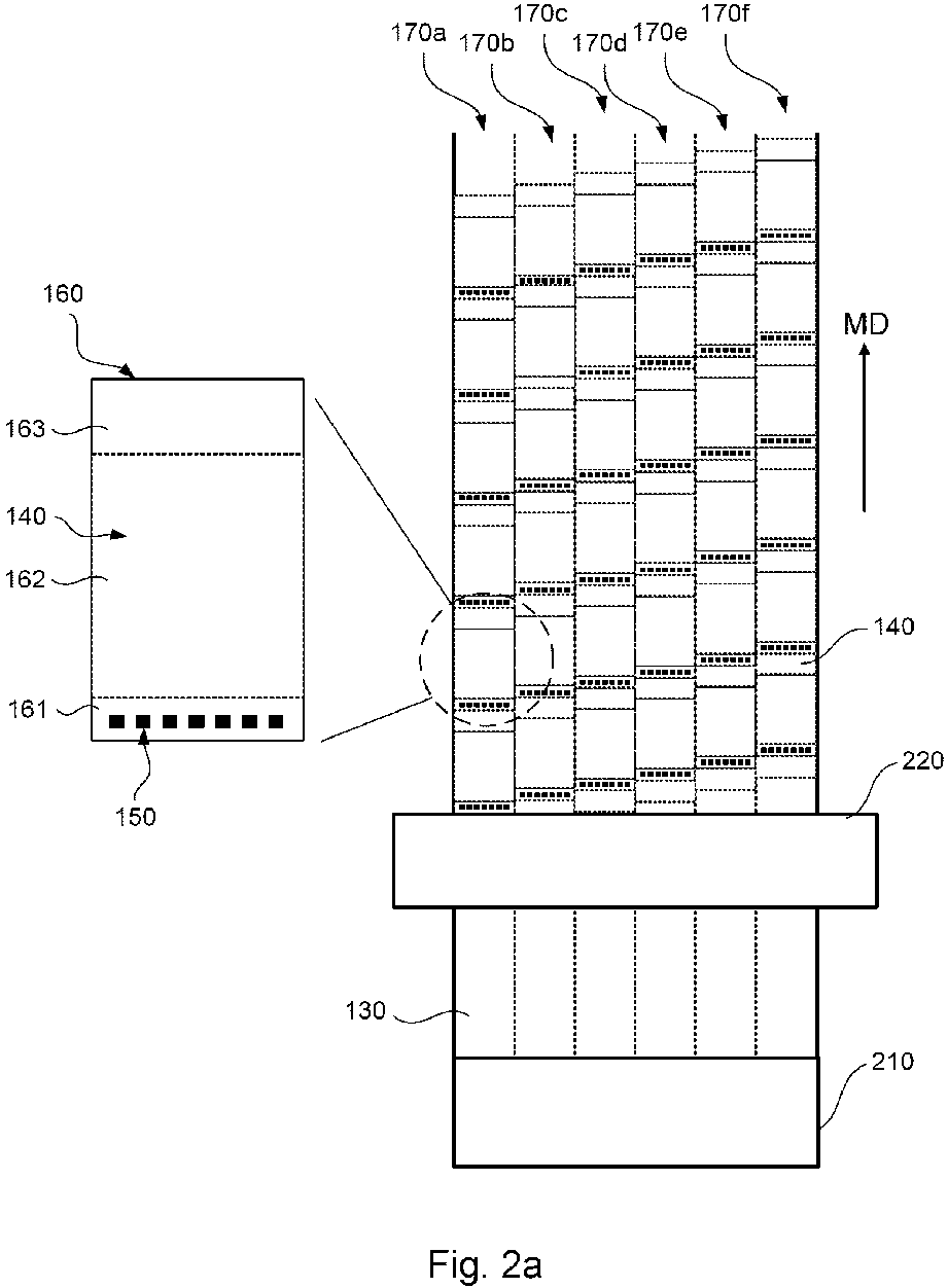
- the decor layer 140 is preferably cyclic in the machine direction MD. This means that a repetitive series of decor layers 140 are printed on the paperboard web 130 in the machine direction during printing. Since the test pattern 150 is fixed in relation to the decor layer 140, the test pattern 150 is preferably also cyclic in the machine direction MD. This is further illustrated in Fig. 2a .
- the test pattern may be printed together with the decor layer at the same constant speed, or at least at the same constant speed but in different occasions.
- the speed is the production speed of the converting unit, that may be same as the feeding speed of the paperboard web.
- the converting unit 200 further comprises an inspection unit 260 which is configured to inspect the test element(s) of the test pattern 150 and thereby the quality of each nozzle.
- the inspection unit 260 may analyze different characteristics of the test element, such as color, continuity, opacity, color intensity, blurriness, etc. of the test element. Any of the characteristics may be analyzed by the inspection unit 260.
- the continuity of the test element is analyzed. The continuity of the test element is directly related to the quality of the nozzles, and by inspection it is indicated whether the nozzle associated with the test element is defective or not.
- An in-line defect inspection system in the form of the inspection unit 260 is able to detect errors in the nozzles by investigating the test elements across the entire package. Notably, in some embodiments the inspected test element will partly be hidden once the final package is folded.
- a test element also referred to as a design element, may be interpreted as an element that forces all nozzles of a predetermined number of nozzles to jet onto the substrate.
- a controller 300 may be provided in, or in conjunction with (such as remote from), the converting unit 200 to control the operation of the inspection unit 260.
- the controller 300 may be a digital processing unit or the like.
- the controller 300 may also be in electronic communication with the feeding unit(s) as well as the ink-jet print module 220 to control their respective function.
- the inspection unit 260 comprises a camera.
- the inspection unit 260 is configured to take an image of the test element(s) of the test pattern 150.
- the controller 300 is configured to analyze the image from the inspection unit 260 with regards to a reference representation of the plurality of nozzles of the print module 220, such as a reference image of 100% well-functioning nozzles. If the captured image comprises deviations from the reference representation, these deviations are processed and associated with specific nozzles of the print module 220 in order to determine fault nozzles of the print module 220.
- the inspection unit 260 may comprise other means for visual inspection.
- the converting unit 200 may comprise a drying station 230 configured to dry the decor layer 140, as well as the test pattern 150.
- the converting unit 200 may further comprise a creasing station 240 configured to provide a crease line pattern to the printed paperboard web 130, and optionally at least one lamination station 250 configured to laminate at least a further layer to the printed and creased paperboard web 130.
- the so formed laminated packaging material web 100 may be transferred to a cutting and/or folding station (not shown) to form a package.
- the different elements of the converting unit 200 may be arranged in the following order, upstream to downstream as illustrated in Fig. 1 ; feeding unit(s) 210, ink-jet print module 220, inspection unit 260, drying station 230, creasing station 240, lamination station 250.
- a priming station (not shown) may also be provided in the converting unit 200, before the ink-jet printer 220.
- the controller 300 mentioned above may also control the operation of the priming station, as well as the drying station 230, creasing station 240 and lamination station 250.
- Fig. 2a illustrates a paperboard web 130 moving through a part of the converting unit 200 described above. More specifically, the paperboard web 130 is fed from the feeding unit 210, in the machine direction MD, towards the ink-jet print module 220 where the decor layer 140 and the test pattern 150 are printed onto the paperboard web 130. The decor layer 140 and the test pattern 150 are printed periodically onto the paperboard web 130. Preferably, the periodicity of the print is both in parallel with and perpendicularly to the machine direction MD, as in Fig. 2a . As a result, quality inspection, also referred to as print defect detection, is provided, with full decor design variability. This is because a static, reoccurring, test element is printed on all of the packages to be formed.
- the test pattern, particularly at least one test element 151, of each section on each lane 170a-f may extend along the whole width of the individual lane 170a-f including the stated unprinted decor area by the help of being formed by all nozzles corresponding to the lane 170a-f, see Fig.4 .
- all nozzles of the ink-jet print module 220 may be controlled by forming the test pattern of each lane 170a-f as explained above. This helps also to check some nozzles that are not needed for the current print cycle but that some nozzles may be needed for a later print cycle.
- the sections 160 may also be referred to as blanks from which a package is to be formed, especially if the web of packaging material later is cut into individual sections for a blank-fed packaging machine.
- the décor and test pattern prints are preferably identical in the corresponding sections 160 for a specific lane 170a-f, since the packages to be formed from the respective sections 160 are most likely to have the same print when produced by the same package forming unit.
- Each section 160 includes a number of sub-sections which correspond to different parts of the package to be formed.
- each section 160 of the printed paperboard web 130 includes three sub-sections 161-163 which correspond to different parts of the package to be formed.
- the sub-sections, or regions, are preferably separated by crease lines, which intended positions are indicated as dotted lines (however in practice, these crease lines may not be formed until downstream the print module 220).
- the crease lines may for instance be formed in the creasing station 240 of the converting unit 200 as briefly mentioned in relation to Fig. 1 .
- the decor layer 140 of the section 160 comprises a bottom area 161, a body area 162 and a top area 163.
- the bottom area 161 corresponds to a bottom part of the package to be formed
- the body area 162 corresponds to a main body part of the package to be formed
- the top area 163 corresponds to an upper part of the package to be formed.
- the upper part of the package is typically the part from which the food or beverage product is to be poured out. Not all sub-sections of the section 160 need to be printed with a decor layer 140.
- each package is formed by folding a section 160 at the crease lines thereof, and appropriate sealing.
- the sections 160 referred to in relation to Fig. 2a thus form part of the laminated packaging material 100.
- the test pattern 150 is preferably printed on each of the multiple sections 160 to be found on each of the packages to be formed.
- the test pattern 150 is at least partly hidden in the folded package.
- a package, folded from a laminated packaging material 100 according to the above will comprise an at least partly hidden test pattern 150.
- the test pattern 150 extends at least partially across the decor layer 140.
- the test pattern 150 may instead comprise a test element that covers the full package width on each individual package to be formed.
- the test pattern 150 would for instance be in the shape of one or more continuous lines that would extend from one long side of the section 160 in Fig. 2a to the other long side.
- the test pattern 150 also has a fixed position in relation to the decor layer.
- the test pattern 150 is printed in proximity to the bottom area 161 of the decor layer 140.
- "in proximity” could mean everything from within the bottom area 161, to bridging the bottom area 161 and the body area 162.
- the test pattern 150 may as well extend across the entire decor layer 140, such as between the long sides of the decor layer 140.
- the test pattern is shown as black squares. Each square represents a test element.
- each test element of the test pattern 150 may for instance represent a unique color.
- test pattern 150 is provided as a plurality of test elements 151.
- Each test element 151 is a single line extending across at least the same width as the decor layer 140.
- Each test element 151 is provided by a unique print head 222a-d being controlled to print from all nozzles covering the desired width of the test element 151.
- quality inspection of the nozzles used to print the decor layer 140 and the test pattern 150 is performed by checking if there is any deviation in the test elements 151, compared to perfectly printed continuous lines.
- Fig. 3 an embodiment of a continuous in-line method for quality inspection of nozzles of an ink-jet print module 220 is illustrated.
- the method may be performed in the converting unit 200 as described above.
- the converting unit 200 is configured to perform the method as will now be described.
- all aspects disclosed with regard to the method may be implied also for the converting unit 200, as well as the other way around.
- the method includes a step S5 of forwarding a paperboard web 130 continuously, preferably at a substantially constant speed, in a machine direction MD.
- the machine direction MD may be defined as the direction parallel to the movement of the paperboard web 130 through a manufacturing equipment such as a converting unit 200, or as the circumferential direction of a roll of paper used for providing the paperboard web 130.
- a step of ink-jet printing S10 a decor layer 140 on the paperboard web 130 is performed, using the ink-jet module 220, and more specifically the nozzles included therein.
- the paperboard layer 130 may comprise paper, paperboard or other cellulose-based material.
- Ink-jet printing is a type of digital printing or computer printing. During ink-jet printing, a digital image is recreated by propelling droplets of ink onto a substrate, such as a paperboard layer 130 or a primer layer (not shown).
- the method may further comprise other printing techniques, such as flexographic printing, and the decor layer 140 may hence be obtained by ink-jet printing only, or by a hybrid approach combining two or more printing techniques. In other words, the decor layer 140 may be ink-jet printed and flexography printed.
- a step S15 of printing a test pattern 150 comprising a test element (further described above) onto the paperboard web 130 is performed.
- the step S10 of printing the decor layer 140 and the step S15 of printing the test pattern 150 are performed substantially at the same time, for instance by continuously activating print heads 222a-d of the ink-jet print module 220.
- the step S15 of printing the test pattern onto the paperboard web 130 is performed by activating a plurality of the nozzles of the ink-jet print module 220.
- a purpose of providing the test patterns 150 (including test elements) is that the nozzles can be closely monitored and inspected during use of the converting unit 200. In other words, the method is an in-line quality inspection method.
- the nozzles are inspected in a step S20, using for instance the inspection unit 260 arranged downstream of the ink-jet print module 220 shown in Fig 1 .
- the test pattern 150 is printed in a way such that it has a fixed position in relation to the decor layer 140.
- the inspection unit 260 inspects the nozzles via their output in the form of the test pattern 150 including the test elements.
- the test elements are indicative of the quality of each nozzle of the plurality of nozzles of the ink-jet print module 220.
- the ink-jet print module 220 comprises a plurality of print heads, comprising the plurality of nozzles. Each print head is configured to print a unique color, and the test pattern 150 comprises a test element for each unique color.
- the plurality of nozzles of the ink-jet print module 220 are activated at the same time.
- the plurality of nozzles may be all, or a subset of all nozzles of the ink-jet print module 220.
- the test element is a continuous design element as briefly described in relation to Fig. 1 above.
- the test pattern 150 extends at least partially across the entire decor layer 140, preferably across the entire decor layer 140.
- the steps S10 and S15 of printing a decor layer 140 and a test pattern 150 on the paperboard web 130 are performed repeatedly along the paperboard web 130.
- the paperboard web 130 when moving through a converting unit 200 as disclosed herein, has a print, or coating, which is cyclic along the longitudinal direction of the paperboard web 130.
- the decor layer 140 is cyclic in the machine direction MD.
- the test pattern 150 which is fixed in relation to the decor layer in its position, is cyclic in the machine direction MD.
- the printed paperboard web 130 is preferably divided into multiple sections 160 which are to be folded into respective packages.
- the packages may also be referred to as food or beverage containers.
- the sections 160 are preferably separated by a crease line pattern which may be provided in a step S40 after drying the printed decor layer 140 and the printed test pattern 150.
- the crease line pattern facilitates the formation of a packaging container from the laminated packaging material web 100, see Fig. 1 .
- the crease line pattern is preferably repeated in the machine direction MD.
- the decor layer 140 is printed within the sections 160 of the printed paperboard web.
- the test pattern 150 is printed on each of the multiple sections 160 to be found on each of the formed packages, and the position of the test pattern 150 is preferably such that the test pattern 150 is at least partly hidden after folding the paperboard web 130 to form the package.
- the decor layer 140 is printed in regions referred to as a bottom area 161, a body area 162 and a top area 163.
- a bottom area 161 corresponds to a bottom part of the package to be formed.
- the body area 162 corresponds to a body part of the package to be formed.
- the top area 163 corresponds to an upper part of the package to be formed.
- the test pattern 150 is printed in proximity to the bottom area 163 of the decor layer 140 on the section 160 of the printed paperboard web.
- packages in the shape of quadrangular prism or like that is formed by folding the filled and sealed laminated packaging material obtained from the paperboard web 130 can have the test pattern 150 on the bottom face thereof, so, while standing on a surface, the test pattern 150 becomes out of sight.
Landscapes
- Engineering & Computer Science (AREA)
- Quality & Reliability (AREA)
- Mechanical Engineering (AREA)
- Ink Jet (AREA)
- Accessory Devices And Overall Control Thereof (AREA)
- Particle Formation And Scattering Control In Inkjet Printers (AREA)
Abstract
Description
- The invention relates to a method for quality inspection of nozzles of an ink-jet print module, a converting unit, a laminated packaging material, and a package folded from a laminated packaging material.
- Packaging containers of the single use disposable type for liquid foods are often produced from a laminated packaging material. The laminated packaging material is produced as a continuous web, which is either used in a roll-fed package forming and filling machine or cut into separate blanks for use in a blank-fed package forming and filling machine.
- The laminated packaging material is produced using a converting procedure in which multiple materials are joined and processed to form the ready-to-use web of laminated packaging material.
- During the converting process a paperboard web, forming the core layer of the laminated packaging material, may be digitally printed on the outside (i.e. the side intended as the exterior side of the laminated packaging material) for example by ink-jet printing.
- Print defects may arise from misfiring, non-jetting, clogged or blocked nozzles, crooked or in any way defective nozzles of the print heads. It is important to be able to detect such defects and accurately associate them with the specific faulty nozzle, single nozzle or multiple nozzles, in order to ensure a desired quality of the packaging material web and optimum print quality performance of the digital printing process.
- Current techniques for print defect detection either rely on human visual inspection, which is slow, costly and suffers from subjective instability, or rely on complex image recognition systems which are costly and sensitive.
- One of a prior publication is
US2009189928A1 that discloses an image forming apparatus that forms images with a recording unit by ejecting inks, as coloring material, and treatment liquid from nozzles onto a recording medium, and that prints detection images for each color of ink so as to overlap each other. The recording unit prints a nozzle-check pattern. The nozzle-check patterns are printed between one image region and another image region formed with images instructed for image forming by a user, a specific example thereof being printing in a non-image region provided between each page. The size (width W) of the non-image region is determined based on the size of the nozzle-check patterns. - One other prior publication is
US2017021612A1 that discloses a method of testing a print head, a printing method, a device for testing a print head, and a printer which are capable of accurately detecting an abnormality of a recording element in a short period of time. The print head prints a predetermined test chart, and the test chart is tested whether there is an abnormal nozzle based on a result of the output, or not. The test chart is printed in a margin region of the paper to perform the test of the print head during the execution of the printing job. Therefore, printing of an image on the paper is performed with a margin. In a case where an image is printed on continuous paper, test charts are printed in margin regions formed between respective images. - Both publications talk about a non-image region or a margin to print check pattern or test chart that are most probably cut-out and wasted after control actions.
- As a result, there is a need in the art for improvements of print defect detection in manufacturing techniques for laminated packaging material webs.
- It is an object of the invention to at least partly overcome one or more of the above-identified limitations of the prior art. In particular, it is an object to provide a reliable and efficient method for detecting printing defects generated by faulty nozzles of an ink-jet printing module.
- According to an aspect, a method for quality inspection of nozzles of an ink-jet print module is provided. The method comprises forwarding a paperboard web continuously at a substantially constant speed in a machine direction; printing a decor layer on the paperboard web using the ink-jet print module; and printing a test pattern comprising a test element on the paperboard web by activating a plurality of the nozzles, which are intended to be inspected, and the test element having a fixed position in relation to the decor layer. The test pattern is indicative of the quality of each nozzle of the plurality of nozzles.
- The quality of the nozzles of the ink-jet print module used in printing decor on paperboard webs to form packaging materials can be easily tested due to the fixed positioning of the test pattern in relation to the decor layer, which gives a quick and accurate indication of whether a particular nozzle is faulty or not.
- According to another aspect, a converting unit configured to continuously manufacture a packaging material web is provided. The converting unit comprises a feeding unit configured to continuously forward a paperboard web at a substantially constant speed in a machine direction, an ink-jet print module comprising a plurality of print heads with a plurality of nozzles and being configured to print a decor layer and a test pattern comprising a test element on the paperboard web. The test pattern is printed by activating the plurality of nozzles, such that the test pattern extends or is arranged at a fixed position in relation to the decor layer. The test pattern is indicative of the quality of each nozzle of the plurality of nozzles.
- According to yet another aspect, a laminated packaging material is provided. The laminated packaging material comprises a paperboard web having a decor layer and a test pattern comprising a test element printed thereon. The test pattern extends at least partially across the decor layer and has a fixed position in relation to the decor layer.
- According to a further aspect, a package folded from a laminated packaging material according to the above is provided. The test pattern is at least partly hidden in the folded package.
- A general idea behind the inventive concept associated with the different aspects described above, is that each element of the test pattern is associated with a specific nozzle, which is detectable by inspection. This provides a quick and reliable way of identifying a nozzle which is faulty and in need of service.
- Detecting print defects is significantly easier if the test elements are fixed in relation to the decor layer. Extension of the test pattern with its test elements across the web enables error detection up to the full paperboard web width which reduces the inspection system complexity. Moreover, the quality inspection method is capable of detecting a single faulty digital printing nozzle, or even two neighboring nozzles, while production is running.
- Still other objectives, features, aspects and advantages of the invention will appear from the following detailed description as well as from the drawings.
- Embodiments of the invention will now be described, by way of example, with reference to the accompanying schematic drawings, in which
-
Fig. 1 is a schematic view of a converting unit, -
Fig. 2a is a top view of a paperboard web moving through a part of the converting unit ofFig.1 , -
Fig. 2b is a top view of a section of a paperboard web, -
Fig. 3 is a flow chart of a method for quality inspection of nozzles of an ink-jet print module, and -
Fig. 4 is an alternative top view of a section of a paperboard web. - A package, such as a liquid food or beverage container, is formed by folding blanks of a laminated packaging material. The packaging material is typically manufactured in a manufacturing unit, such as a converting unit. In the converting unit, a decor layer is printed onto a substrate which, after a series of process steps, eventually forms part of the laminated packaging material. In the following description, the substrate is referred to as a paperboard material. To inspect the quality of the print and relate eventual defects to one or more faulty nozzles, an in-line method and system for quality inspection of nozzles is provided and which will be described in the following.
- With reference to
Fig. 1 , a convertingunit 200 configured to manufacture a laminated packaging material web 100 is illustrated schematically. The convertingunit 200 includes at least onefeeding unit 210, here illustrated as two feeding rolls. The feeding unit(s) 210 is configured to continuously forward apaperboard web 130 at a substantially constant speed, preferably in the machine direction MD as indicated by the arrow markings inFig. 1 , for example on 200 m/min or faster, particularly 230-280 m/min, more particularly 240-275 m/min, most particularly 270-275 m/min. - The converting
unit 200 further comprises an ink-jet print module 220 comprising a plurality ofprint heads 222a-d, eachprint head 222a-d having a plurality of nozzles. Preferably, the plurality of nozzles of the ink-jet print module 220 extends across thepaperboard web 130 in a transverse direction which is perpendicular to the machine direction MD. The ink-jet print module 220 is configured to print adecor layer 140, as well as atest pattern 150 comprising at least one test element (not shown), on thepaperboard web 130. For instance, there may be one printed test pattern perprint head 222a-d across the printed substrate, which in this case is thepaperboard web 130. This reduces the challenges faced by the in-line detection system to find the potentially misfiring, crooked or in any way faulty nozzles, and makes nozzle inspection possible without complex image recognition system in place. - In
Fig. 1 , the ink-jet print module 220 is illustrated as a support cylinder and a plurality ofprint heads 222a-d for cyan C, magenta M, yellow Y and black K. It should be noted that the exact configuration of the ink-jet print module 220 may be different depending on the particular application; for example, the ink-jet printer 220 may comprisemultiple print heads 222a-d arranged in the machine direction and/or the transverse direction in order to cover the entire width of thepaperboard web 130. Eachprint head 222a-d may be configured to print a unique color. Alternately, as shown inFig. 1 , there areseveral print heads 222a-d for each unique color. Thus, the printedtest pattern 150 may comprise a test element for each unique color and/or for eachprint head 222a-d. - Printing of the
test pattern 150, including test elements, onto thepaperboard web 130 is performed by activating the plurality of nozzles of the ink-jet print module 220, such that thetest pattern 150 extends at a fixed position in relation to thedecor layer 140. Thetest pattern 150 is indicative of the quality of each nozzle of the plurality of nozzles. Preferably, each nozzle of the plurality of nozzles are activated simultaneously, i.e. at the same time. The fixed position of thetest pattern 150 in relation to thedecor layer 140 is to ensure reproducibility as well as traceability of thetest pattern 150. - The
test pattern 150, which includes a test element, may extend in a direction transverse to the machine direction MD, or in parallel, or in any angle of choice with respect to the machine direction MD. The test element may for instance be a design element, such as a continuous design element, for instance a continues line formed by activating a plurality of the nozzles, which are intended to be inspected as inFig.2b orFig.4 . The design element is unique, and in a full package width, it may be fully visible only when the package is unfolded, i.e. prior to folding the laminated packaging material 100 into a package. In fact, the test pattern is to be understood as having at least one test element, such as a plurality of design elements. The plurality of design elements preferably represents the number of colors used in printing. - In some cases, the
test pattern 150 may be part of thedecor layer 140. Optionally, thetest pattern 150 is separate from thedecor layer 140. Thus, thetest pattern 150 and thedecor layer 140 should not be interpreted as being totally separate from one another. Rather, they may be separate from each other, or coincide with each other. - For instance, the
test pattern 150 extends at least partially across the decor layer. Preferably, thetest pattern 150 extends across the entire decor layer. The plurality of nozzles of the ink-jet print heads 222a-c may extend transversely across theentire paperboard web 130 to achieve this. Moreover, thetest pattern 150 may extend over theentire decor layer 140 in a continuous or non-continuous manner. However, in some cases, there may be gaps between nozzles, such that even if all nozzles are activated, thetest pattern 150, if in the shape of a line, may not be continuous. In other words, thetest pattern 150 may be non-continuous. For instance, thetest pattern 150 may be one whole line, two or more parallel lines, dots, square shapes, shorter line sections, etc. - The
decor layer 140 is preferably cyclic in the machine direction MD. This means that a repetitive series ofdecor layers 140 are printed on thepaperboard web 130 in the machine direction during printing. Since thetest pattern 150 is fixed in relation to thedecor layer 140, thetest pattern 150 is preferably also cyclic in the machine direction MD. This is further illustrated inFig. 2a . The test pattern may be printed together with the decor layer at the same constant speed, or at least at the same constant speed but in different occasions. The speed is the production speed of the converting unit, that may be same as the feeding speed of the paperboard web. - Again referring to
Fig. 1 , downstream of the ink-jet print module 220, the convertingunit 200 further comprises aninspection unit 260 which is configured to inspect the test element(s) of thetest pattern 150 and thereby the quality of each nozzle. For instance, theinspection unit 260 may analyze different characteristics of the test element, such as color, continuity, opacity, color intensity, blurriness, etc. of the test element. Any of the characteristics may be analyzed by theinspection unit 260. Preferably, the continuity of the test element is analyzed. The continuity of the test element is directly related to the quality of the nozzles, and by inspection it is indicated whether the nozzle associated with the test element is defective or not. - An in-line defect inspection system in the form of the
inspection unit 260 is able to detect errors in the nozzles by investigating the test elements across the entire package. Notably, in some embodiments the inspected test element will partly be hidden once the final package is folded. In this disclosure, a test element, also referred to as a design element, may be interpreted as an element that forces all nozzles of a predetermined number of nozzles to jet onto the substrate. - The different characteristics of the test element are compared to a predetermined test element object, which in turn is linked to the quality of the nozzles. A
controller 300 may be provided in, or in conjunction with (such as remote from), the convertingunit 200 to control the operation of theinspection unit 260. For instance, thecontroller 300 may be a digital processing unit or the like. Thecontroller 300 may also be in electronic communication with the feeding unit(s) as well as the ink-jet print module 220 to control their respective function. - In one embodiment, the
inspection unit 260 comprises a camera. Theinspection unit 260 is configured to take an image of the test element(s) of thetest pattern 150. Thecontroller 300 is configured to analyze the image from theinspection unit 260 with regards to a reference representation of the plurality of nozzles of theprint module 220, such as a reference image of 100% well-functioning nozzles. If the captured image comprises deviations from the reference representation, these deviations are processed and associated with specific nozzles of theprint module 220 in order to determine fault nozzles of theprint module 220. In other embodiments theinspection unit 260 may comprise other means for visual inspection. - Furthermore, the converting
unit 200 may comprise a drying station 230 configured to dry thedecor layer 140, as well as thetest pattern 150. The convertingunit 200 may further comprise a creasing station 240 configured to provide a crease line pattern to the printedpaperboard web 130, and optionally at least one lamination station 250 configured to laminate at least a further layer to the printed and creasedpaperboard web 130. After printing, inspecting, drying and creasing, the so formed laminated packaging material web 100 may be transferred to a cutting and/or folding station (not shown) to form a package. - The different elements of the converting
unit 200 may be arranged in the following order, upstream to downstream as illustrated inFig. 1 ; feeding unit(s) 210, ink-jet print module 220,inspection unit 260, drying station 230, creasing station 240, lamination station 250. A priming station (not shown) may also be provided in the convertingunit 200, before the ink-jet printer 220. Apart from controlling the operation of the feeding unit(s) 210, ink-jet print module 220 andinspection unit 260, thecontroller 300 mentioned above may also control the operation of the priming station, as well as the drying station 230, creasing station 240 and lamination station 250. -
Fig. 2a illustrates apaperboard web 130 moving through a part of the convertingunit 200 described above. More specifically, thepaperboard web 130 is fed from thefeeding unit 210, in the machine direction MD, towards the ink-jet print module 220 where thedecor layer 140 and thetest pattern 150 are printed onto thepaperboard web 130. Thedecor layer 140 and thetest pattern 150 are printed periodically onto thepaperboard web 130. Preferably, the periodicity of the print is both in parallel with and perpendicularly to the machine direction MD, as inFig. 2a . As a result, quality inspection, also referred to as print defect detection, is provided, with full decor design variability. This is because a static, reoccurring, test element is printed on all of the packages to be formed. - The printed
paperboard web 130 is preferably divided into a plurality ofpaperboard web sections 160, also referred to as "sections". Longitudinally alignedsections 160 belong to thesame lane 170a-f. As shown inFig. 2a , thepaperboard web 130 may havemultiple lanes 170a-f; and eachlane 170a-f may havemultiple sections 160 longitudinally aligned. On such aweb 130, there may be unprinted decor areas between thelanes 170a-f that may be left for slitting to separate thelanes 170a-ffrom each other, for instance, to make them ready to be fed a roll-fed package forming and filling machine or to be cut further intosections 160 from asingle lane 170a-f. In the ideal way, no paperboard web is wasted while separating the trailing sections on a lane and/or separating the lanes from each other. For aweb 130 havingmultiple lanes 170a-f, the test pattern, particularly at least onetest element 151, of each section on eachlane 170a-f may extend along the whole width of theindividual lane 170a-f including the stated unprinted decor area by the help of being formed by all nozzles corresponding to thelane 170a-f, seeFig.4 . Although thesections 160 and the test patterns are shifted in machine direction MD in alllanes 170a-f (seeFig.2a ), all nozzles of the ink-jet print module 220 may be controlled by forming the test pattern of eachlane 170a-f as explained above. This helps also to check some nozzles that are not needed for the current print cycle but that some nozzles may be needed for a later print cycle. - The
sections 160 may also be referred to as blanks from which a package is to be formed, especially if the web of packaging material later is cut into individual sections for a blank-fed packaging machine. - The décor and test pattern prints are preferably identical in the corresponding
sections 160 for aspecific lane 170a-f, since the packages to be formed from therespective sections 160 are most likely to have the same print when produced by the same package forming unit. - Each
section 160 includes a number of sub-sections which correspond to different parts of the package to be formed. InFig. 2a , eachsection 160 of the printedpaperboard web 130 includes three sub-sections 161-163 which correspond to different parts of the package to be formed. The sub-sections, or regions, are preferably separated by crease lines, which intended positions are indicated as dotted lines (however in practice, these crease lines may not be formed until downstream the print module 220). The crease lines may for instance be formed in the creasing station 240 of the convertingunit 200 as briefly mentioned in relation toFig. 1 . - In the embodiment shown in
Fig. 2a , thedecor layer 140 of thesection 160 comprises abottom area 161, abody area 162 and atop area 163. Thebottom area 161 corresponds to a bottom part of the package to be formed, thebody area 162 corresponds to a main body part of the package to be formed, and thetop area 163 corresponds to an upper part of the package to be formed. The upper part of the package is typically the part from which the food or beverage product is to be poured out. Not all sub-sections of thesection 160 need to be printed with adecor layer 140. - From the above description, it is clear that a number of packages may be obtained from the packaging material web formed by converting
unit 200. Each package is formed by folding asection 160 at the crease lines thereof, and appropriate sealing. Thesections 160 referred to in relation toFig. 2a thus form part of the laminated packaging material 100. Moreover, thetest pattern 150 is preferably printed on each of themultiple sections 160 to be found on each of the packages to be formed. Preferably, thetest pattern 150 is at least partly hidden in the folded package. Thus, if thetest pattern 150 is printed at thebottom area 163 of thesection 160, a package, folded from a laminated packaging material 100 according to the above, will comprise an at least partly hiddentest pattern 150. - As seen in
Fig. 2a , thetest pattern 150 extends at least partially across thedecor layer 140. In another embodiment, not shown, thetest pattern 150 may instead comprise a test element that covers the full package width on each individual package to be formed. In that case, thetest pattern 150 would for instance be in the shape of one or more continuous lines that would extend from one long side of thesection 160 inFig. 2a to the other long side. - The
test pattern 150 also has a fixed position in relation to the decor layer. Preferably, thetest pattern 150 is printed in proximity to thebottom area 161 of thedecor layer 140. In reality, "in proximity" could mean everything from within thebottom area 161, to bridging thebottom area 161 and thebody area 162. Thetest pattern 150 may as well extend across theentire decor layer 140, such as between the long sides of thedecor layer 140. InFig. 2a , the test pattern is shown as black squares. Each square represents a test element. Furthermore, each test element of thetest pattern 150 may for instance represent a unique color. - In
Fig. 2b another example of asection 160 is shown, wherein thetest pattern 150 is provided as a plurality oftest elements 151. Eachtest element 151 is a single line extending across at least the same width as thedecor layer 140. Eachtest element 151 is provided by aunique print head 222a-d being controlled to print from all nozzles covering the desired width of thetest element 151. Hence, quality inspection of the nozzles used to print thedecor layer 140 and thetest pattern 150 is performed by checking if there is any deviation in thetest elements 151, compared to perfectly printed continuous lines. - Turning now to
Fig. 3 , an embodiment of a continuous in-line method for quality inspection of nozzles of an ink-jet print module 220 is illustrated. The method may be performed in the convertingunit 200 as described above. Conversely, the convertingunit 200 is configured to perform the method as will now be described. Moreover, all aspects disclosed with regard to the method may be implied also for the convertingunit 200, as well as the other way around. - The method includes a step S5 of forwarding a
paperboard web 130 continuously, preferably at a substantially constant speed, in a machine direction MD. The machine direction MD may be defined as the direction parallel to the movement of thepaperboard web 130 through a manufacturing equipment such as a convertingunit 200, or as the circumferential direction of a roll of paper used for providing thepaperboard web 130. Next, a step of ink-jet printing S10 adecor layer 140 on thepaperboard web 130 is performed, using the ink-jet module 220, and more specifically the nozzles included therein. - The
paperboard layer 130 may comprise paper, paperboard or other cellulose-based material. Ink-jet printing is a type of digital printing or computer printing. During ink-jet printing, a digital image is recreated by propelling droplets of ink onto a substrate, such as apaperboard layer 130 or a primer layer (not shown). The method may further comprise other printing techniques, such as flexographic printing, and thedecor layer 140 may hence be obtained by ink-jet printing only, or by a hybrid approach combining two or more printing techniques. In other words, thedecor layer 140 may be ink-jet printed and flexography printed. - Following the printing of the
decor layer 140, a step S15 of printing atest pattern 150 comprising a test element (further described above) onto thepaperboard web 130 is performed. Optionally, the step S10 of printing thedecor layer 140 and the step S15 of printing thetest pattern 150 are performed substantially at the same time, for instance by continuously activatingprint heads 222a-d of the ink-jet print module 220. The step S15 of printing the test pattern onto thepaperboard web 130 is performed by activating a plurality of the nozzles of the ink-jet print module 220. As is clear from the above disclosure, a purpose of providing the test patterns 150 (including test elements) is that the nozzles can be closely monitored and inspected during use of the convertingunit 200. In other words, the method is an in-line quality inspection method. - The nozzles are inspected in a step S20, using for instance the
inspection unit 260 arranged downstream of the ink-jet print module 220 shown inFig 1 . Thetest pattern 150 is printed in a way such that it has a fixed position in relation to thedecor layer 140. Theinspection unit 260 inspects the nozzles via their output in the form of thetest pattern 150 including the test elements. Hence, the test elements are indicative of the quality of each nozzle of the plurality of nozzles of the ink-jet print module 220. The ink-jet print module 220 comprises a plurality of print heads, comprising the plurality of nozzles. Each print head is configured to print a unique color, and thetest pattern 150 comprises a test element for each unique color. - Preferably, the plurality of nozzles of the ink-
jet print module 220 are activated at the same time. The plurality of nozzles may be all, or a subset of all nozzles of the ink-jet print module 220. Moreover, the test element is a continuous design element as briefly described in relation toFig. 1 above. As mentioned, thetest pattern 150 extends at least partially across theentire decor layer 140, preferably across theentire decor layer 140. - The steps S10 and S15 of printing a
decor layer 140 and atest pattern 150 on thepaperboard web 130 are performed repeatedly along thepaperboard web 130. In other words, thepaperboard web 130, when moving through a convertingunit 200 as disclosed herein, has a print, or coating, which is cyclic along the longitudinal direction of thepaperboard web 130. Put differently, thedecor layer 140 is cyclic in the machine direction MD. Also thetest pattern 150, which is fixed in relation to the decor layer in its position, is cyclic in the machine direction MD. - After quality inspection S20 of the nozzles by the
inspection unit 260, an optional step S30 of drying thedecor layer 140 is performed. The printedpaperboard web 130 is preferably divided intomultiple sections 160 which are to be folded into respective packages. The packages may also be referred to as food or beverage containers. - The
sections 160 are preferably separated by a crease line pattern which may be provided in a step S40 after drying the printeddecor layer 140 and the printedtest pattern 150. The crease line pattern facilitates the formation of a packaging container from the laminated packaging material web 100, seeFig. 1 . The crease line pattern is preferably repeated in the machine direction MD. Along the length of thepaperboard web 130, thedecor layer 140 is printed within thesections 160 of the printed paperboard web. Also thetest pattern 150 is printed on each of themultiple sections 160 to be found on each of the formed packages, and the position of thetest pattern 150 is preferably such that thetest pattern 150 is at least partly hidden after folding thepaperboard web 130 to form the package. - In a
section 160 of thepaperboard web 130, thedecor layer 140 is printed in regions referred to as abottom area 161, abody area 162 and atop area 163. Optionally, only one or a few of the regions of a section is printed on. Thebottom area 161 corresponds to a bottom part of the package to be formed. Thebody area 162 corresponds to a body part of the package to be formed. Thetop area 163 corresponds to an upper part of the package to be formed. Preferably, thetest pattern 150 is printed in proximity to thebottom area 163 of thedecor layer 140 on thesection 160 of the printed paperboard web. Especially, packages in the shape of quadrangular prism or like that is formed by folding the filled and sealed laminated packaging material obtained from thepaperboard web 130 can have thetest pattern 150 on the bottom face thereof, so, while standing on a surface, thetest pattern 150 becomes out of sight. - From the description above follows that, although various embodiments of the invention have been described and shown, the invention is not restricted thereto, but may also be embodied in other ways within the scope of the subject-matter defined in the following claims. The all features of one aspect may also be valid for another aspect of the invention as long as falls in the scope of the following claims. For instance, any feature mentioned for the method, is also valid for the converting unit in same or as a feature corresponding to the converting unit. On the other hand, any feature of paperboard web stated is also valid for the laminated packaging material formed in the converting unit.
Claims (19)
- A method for quality inspection of nozzles of an ink-jet print module, the method comprising:forwarding a paperboard web continuously at a substantially constant speed in a machine direction,printing a decor layer on the paperboard web using the ink-jet print module, andprinting a test pattern comprisingat least one test element on the paperboard web by activating a plurality of the nozzles, which are intended to be inspected, andhaving a fixed position in relation to the decor layer,wherein the test pattern is indicative of the quality of each nozzle of the plurality of nozzles.
- The method according to claim 1, wherein the plurality of nozzles are activated at the same time.
- The method according to any preceding claim, wherein the test element is a continuous design element, such as a continuous line.
- The method according to any preceding claim, wherein the test pattern extends at least partially across the decor layer, preferably wherein the test pattern extends across the entire decor layer.
- The method according to any preceding claim, wherein the ink-jet print module comprises a plurality of print heads, comprising the plurality of nozzles, each print head being configured to print a unique color, and wherein the test pattern comprises a test element for each unique color.
- The method according to any preceding claim, wherein the decor layer is cyclic in the machine direction.
- The method according to any preceding claim, wherein the decor layer comprises a bottom area corresponding to a bottom part of a package to be formed, a body area corresponding to a body part of the package to be formed, and a top area corresponding to an upper part of the package to be formed, wherein the test pattern is printed in proximity to the bottom area of the decor layer.
- The method according to any preceding claim, wherein the paperboard web is intended to be folded and form a package, and wherein the position of the test pattern is such that the test pattern is at least partly hidden after folding the paperboard web to form the package.
- The method according to any preceding claim, wherein the paperboard web has multiple sections to be folded and is configured to form multiple packages, and wherein the test pattern is printed on each of the multiple sections to be found on each of the formed packages.
- The method according to any preceding claim, wherein the continuity of the test element is related to the quality of the nozzles, and wherein the method further comprises inspecting the continuity of the test element.
- The method according to any preceding claim, wherein the paperboard web has multiple lanes, wherein each lane has multiple sections to be folded and is configured to form multiple packages, wherein the test pattern of each section on each lane extends along the full width of the individual lane by the help of being formed by all nozzles corresponding to the lane.
- A converting unit configured to continuously manufacture a laminated packaging material web, comprising a feeding unit configured to continuously forward a paperboard web at a substantially constant speed in a machine direction, an ink-jet print module comprising a plurality of print heads with a plurality of nozzles, and being configured to print a decor layer and a test pattern comprising at least one test element on the paperboard web, wherein the test pattern is printed by activating the plurality of nozzles, such that the test pattern extends at a fixed position in relation to the decor layer, and wherein the test pattern is indicative of the quality of each nozzle of the plurality of nozzles.
- The converting unit according to claim 12, wherein the plurality of nozzles extends across the paperboard web in a transverse direction being perpendicular to the machine direction.
- The converting unit according to claim 12 or 13, further comprising an inspection unit configured to inspect the at least one test element and thereby the quality of each nozzle.
- A laminated packaging material, comprising a paperboard web having a decor layer and a test pattern comprising a test element printed thereon, wherein said test pattern extends at least partially across the decor layer and has a fixed position in relation to the decor layer.
- The laminated packaging material according to claim 15, wherein the test pattern preferably extends across the entire decor layer.
- The laminated packaging material according to claim 15 or 16, wherein the test pattern extends at least partially across the paperboard web, preferably wherein the test pattern extends across the entire paperboard web.
- The laminated packaging material according to any of claims 15 to 17, comprising a plurality of test patterns printed periodically, wherein each test element of the test pattern comprises a unique color.
- A package, folded from a laminated packaging material according to any one of claims 15-18, wherein the test pattern is at least partly hidden in the folded package.
Applications Claiming Priority (1)
| Application Number | Priority Date | Filing Date | Title |
|---|---|---|---|
| EP23157601 | 2023-02-20 |
Publications (2)
| Publication Number | Publication Date |
|---|---|
| EP4417432A2 true EP4417432A2 (en) | 2024-08-21 |
| EP4417432A3 EP4417432A3 (en) | 2024-10-23 |
Family
ID=85285073
Family Applications (1)
| Application Number | Title | Priority Date | Filing Date |
|---|---|---|---|
| EP24158333.5A Pending EP4417432A3 (en) | 2023-02-20 | 2024-02-19 | Method for quality inspection of nozzles of an ink-jet print module |
Country Status (2)
| Country | Link |
|---|---|
| EP (1) | EP4417432A3 (en) |
| WO (1) | WO2024175535A2 (en) |
Citations (2)
| Publication number | Priority date | Publication date | Assignee | Title |
|---|---|---|---|---|
| US20090189928A1 (en) | 2008-01-25 | 2009-07-30 | Fuji Xerox Co., Ltd. | Coloring material recording device, coloring material recording program, and image forming apparatus |
| US20170021612A1 (en) | 2014-05-20 | 2017-01-26 | Fujifilm Corporation | Method of testing print head, printing method, device for testing print head, and printer |
Family Cites Families (6)
| Publication number | Priority date | Publication date | Assignee | Title |
|---|---|---|---|---|
| JP4743499B2 (en) * | 2005-08-24 | 2011-08-10 | 富士フイルム株式会社 | Image forming apparatus |
| US9868311B2 (en) * | 2015-05-18 | 2018-01-16 | The Procter & Gamble Company | In-line case printing system with dynamic sampling frequency and method therefor |
| CN107848296B (en) * | 2015-07-28 | 2019-06-07 | 柯尼卡美能达株式会社 | Image forming apparatus and method for judging good or bad |
| GB2542569B (en) * | 2015-09-22 | 2021-04-28 | Ds Smith Packaging Ltd | A combination of a printed roll and a print roll inventory map |
| DE102017207304A1 (en) * | 2016-05-25 | 2017-11-30 | Heidelberger Druckmaschinen Ag | Method of detecting printing nozzle defects in an inkjet printing machine |
| JP7449134B2 (en) * | 2020-03-23 | 2024-03-13 | 株式会社Screenホールディングス | Printing method and printing device |
-
2024
- 2024-02-19 EP EP24158333.5A patent/EP4417432A3/en active Pending
- 2024-02-19 WO PCT/EP2024/054131 patent/WO2024175535A2/en not_active Ceased
Patent Citations (2)
| Publication number | Priority date | Publication date | Assignee | Title |
|---|---|---|---|---|
| US20090189928A1 (en) | 2008-01-25 | 2009-07-30 | Fuji Xerox Co., Ltd. | Coloring material recording device, coloring material recording program, and image forming apparatus |
| US20170021612A1 (en) | 2014-05-20 | 2017-01-26 | Fujifilm Corporation | Method of testing print head, printing method, device for testing print head, and printer |
Also Published As
| Publication number | Publication date |
|---|---|
| WO2024175535A3 (en) | 2024-10-03 |
| EP4417432A3 (en) | 2024-10-23 |
| WO2024175535A2 (en) | 2024-08-29 |
Similar Documents
| Publication | Publication Date | Title |
|---|---|---|
| US8706017B2 (en) | Duplex web printer system registration technique | |
| US20160155030A1 (en) | Method for printing a material to be printed | |
| JP4502017B2 (en) | Color material recording apparatus, color material recording program, and image forming apparatus | |
| EP2938497B1 (en) | Methods of printing calibration patterns, calibration methods, and printers | |
| JP7762167B2 (en) | Detecting defective nozzles in digital printing systems | |
| EP3964361B1 (en) | A method and system for printing | |
| WO2015178225A1 (en) | Print head inspection method, printing method, print head inspection device, and printer | |
| US20140333691A1 (en) | System and method for visually detecting defective inkjets in an inkjet imaging apparatus | |
| US20120050821A1 (en) | Image recording apparatus | |
| JP6282912B2 (en) | Inspection chart and printing device | |
| WO2024175535A2 (en) | Method for quality inspection of nozzles of an ink-jet print module | |
| JP2012060596A (en) | Image recording device and method | |
| CN109532253B (en) | Printing apparatus and printing method | |
| EP2484533B1 (en) | Printer | |
| WO2011104845A1 (en) | Printer and printing method | |
| JP2006076266A (en) | Inkjet condition detection method and inkjet recording device | |
| EP4190563B1 (en) | Method of manufacturing a mark on a packaging material | |
| JP6151595B2 (en) | Ink jet printing apparatus and step difference correction method thereof | |
| WO2023148575A1 (en) | Printing marks on substrate edge | |
| CN119451824A (en) | Digital printing systems and processes | |
| JP2016203424A (en) | Test pattern and position deviation amount measuring method | |
| EP2819848B1 (en) | Dot detection method and colour image reproduction apparatus | |
| US20080148973A1 (en) | Device for controlling a rotary press for printing a web of material and rotary press | |
| US20250296378A1 (en) | Test pattern forming method | |
| US20260034799A1 (en) | Printing system |
Legal Events
| Date | Code | Title | Description |
|---|---|---|---|
| PUAI | Public reference made under article 153(3) epc to a published international application that has entered the european phase |
Free format text: ORIGINAL CODE: 0009012 |
|
| STAA | Information on the status of an ep patent application or granted ep patent |
Free format text: STATUS: THE APPLICATION HAS BEEN PUBLISHED |
|
| AK | Designated contracting states |
Kind code of ref document: A2 Designated state(s): AL AT BE BG CH CY CZ DE DK EE ES FI FR GB GR HR HU IE IS IT LI LT LU LV MC ME MK MT NL NO PL PT RO RS SE SI SK SM TR |
|
| PUAL | Search report despatched |
Free format text: ORIGINAL CODE: 0009013 |
|
| AK | Designated contracting states |
Kind code of ref document: A3 Designated state(s): AL AT BE BG CH CY CZ DE DK EE ES FI FR GB GR HR HU IE IS IT LI LT LU LV MC ME MK MT NL NO PL PT RO RS SE SI SK SM TR |
|
| RIC1 | Information provided on ipc code assigned before grant |
Ipc: B41J 25/00 20060101ALI20240917BHEP Ipc: B65B 61/26 20060101ALI20240917BHEP Ipc: B41J 3/407 20060101ALI20240917BHEP Ipc: B41J 2/21 20060101AFI20240917BHEP |
|
| STAA | Information on the status of an ep patent application or granted ep patent |
Free format text: STATUS: REQUEST FOR EXAMINATION WAS MADE |
|
| 17P | Request for examination filed |
Effective date: 20250423 |