EP4417430A1 - Small form factor printhead and thermal inkjet printer - Google Patents
Small form factor printhead and thermal inkjet printer Download PDFInfo
- Publication number
- EP4417430A1 EP4417430A1 EP24150558.5A EP24150558A EP4417430A1 EP 4417430 A1 EP4417430 A1 EP 4417430A1 EP 24150558 A EP24150558 A EP 24150558A EP 4417430 A1 EP4417430 A1 EP 4417430A1
- Authority
- EP
- European Patent Office
- Prior art keywords
- printhead
- form factor
- small form
- ink
- attached
- Prior art date
- Legal status (The legal status is an assumption and is not a legal conclusion. Google has not performed a legal analysis and makes no representation as to the accuracy of the status listed.)
- Withdrawn
Links
Images


Classifications
-
- B—PERFORMING OPERATIONS; TRANSPORTING
- B41—PRINTING; LINING MACHINES; TYPEWRITERS; STAMPS
- B41J—TYPEWRITERS; SELECTIVE PRINTING MECHANISMS, i.e. MECHANISMS PRINTING OTHERWISE THAN FROM A FORME; CORRECTION OF TYPOGRAPHICAL ERRORS
- B41J2/00—Typewriters or selective printing mechanisms characterised by the printing or marking process for which they are designed
- B41J2/005—Typewriters or selective printing mechanisms characterised by the printing or marking process for which they are designed characterised by bringing liquid or particles selectively into contact with a printing material
- B41J2/01—Ink jet
-
- B—PERFORMING OPERATIONS; TRANSPORTING
- B41—PRINTING; LINING MACHINES; TYPEWRITERS; STAMPS
- B41J—TYPEWRITERS; SELECTIVE PRINTING MECHANISMS, i.e. MECHANISMS PRINTING OTHERWISE THAN FROM A FORME; CORRECTION OF TYPOGRAPHICAL ERRORS
- B41J2/00—Typewriters or selective printing mechanisms characterised by the printing or marking process for which they are designed
- B41J2/005—Typewriters or selective printing mechanisms characterised by the printing or marking process for which they are designed characterised by bringing liquid or particles selectively into contact with a printing material
- B41J2/01—Ink jet
- B41J2/17—Ink jet characterised by ink handling
- B41J2/175—Ink supply systems ; Circuit parts therefor
- B41J2/17503—Ink cartridges
-
- B—PERFORMING OPERATIONS; TRANSPORTING
- B41—PRINTING; LINING MACHINES; TYPEWRITERS; STAMPS
- B41J—TYPEWRITERS; SELECTIVE PRINTING MECHANISMS, i.e. MECHANISMS PRINTING OTHERWISE THAN FROM A FORME; CORRECTION OF TYPOGRAPHICAL ERRORS
- B41J2/00—Typewriters or selective printing mechanisms characterised by the printing or marking process for which they are designed
- B41J2/005—Typewriters or selective printing mechanisms characterised by the printing or marking process for which they are designed characterised by bringing liquid or particles selectively into contact with a printing material
- B41J2/01—Ink jet
- B41J2/17—Ink jet characterised by ink handling
- B41J2/175—Ink supply systems ; Circuit parts therefor
- B41J2/17503—Ink cartridges
- B41J2/17506—Refilling of the cartridge
-
- B—PERFORMING OPERATIONS; TRANSPORTING
- B41—PRINTING; LINING MACHINES; TYPEWRITERS; STAMPS
- B41J—TYPEWRITERS; SELECTIVE PRINTING MECHANISMS, i.e. MECHANISMS PRINTING OTHERWISE THAN FROM A FORME; CORRECTION OF TYPOGRAPHICAL ERRORS
- B41J2/00—Typewriters or selective printing mechanisms characterised by the printing or marking process for which they are designed
- B41J2/005—Typewriters or selective printing mechanisms characterised by the printing or marking process for which they are designed characterised by bringing liquid or particles selectively into contact with a printing material
- B41J2/01—Ink jet
- B41J2/17—Ink jet characterised by ink handling
- B41J2/175—Ink supply systems ; Circuit parts therefor
- B41J2/17503—Ink cartridges
- B41J2/17506—Refilling of the cartridge
- B41J2/17509—Whilst mounted in the printer
-
- B—PERFORMING OPERATIONS; TRANSPORTING
- B41—PRINTING; LINING MACHINES; TYPEWRITERS; STAMPS
- B41J—TYPEWRITERS; SELECTIVE PRINTING MECHANISMS, i.e. MECHANISMS PRINTING OTHERWISE THAN FROM A FORME; CORRECTION OF TYPOGRAPHICAL ERRORS
- B41J2/00—Typewriters or selective printing mechanisms characterised by the printing or marking process for which they are designed
- B41J2/005—Typewriters or selective printing mechanisms characterised by the printing or marking process for which they are designed characterised by bringing liquid or particles selectively into contact with a printing material
- B41J2/01—Ink jet
- B41J2/17—Ink jet characterised by ink handling
- B41J2/175—Ink supply systems ; Circuit parts therefor
- B41J2/17503—Ink cartridges
- B41J2/17513—Inner structure
-
- B—PERFORMING OPERATIONS; TRANSPORTING
- B41—PRINTING; LINING MACHINES; TYPEWRITERS; STAMPS
- B41J—TYPEWRITERS; SELECTIVE PRINTING MECHANISMS, i.e. MECHANISMS PRINTING OTHERWISE THAN FROM A FORME; CORRECTION OF TYPOGRAPHICAL ERRORS
- B41J2/00—Typewriters or selective printing mechanisms characterised by the printing or marking process for which they are designed
- B41J2/005—Typewriters or selective printing mechanisms characterised by the printing or marking process for which they are designed characterised by bringing liquid or particles selectively into contact with a printing material
- B41J2/01—Ink jet
- B41J2/17—Ink jet characterised by ink handling
- B41J2/175—Ink supply systems ; Circuit parts therefor
- B41J2/17503—Ink cartridges
- B41J2/17526—Electrical contacts to the cartridge
-
- B—PERFORMING OPERATIONS; TRANSPORTING
- B41—PRINTING; LINING MACHINES; TYPEWRITERS; STAMPS
- B41J—TYPEWRITERS; SELECTIVE PRINTING MECHANISMS, i.e. MECHANISMS PRINTING OTHERWISE THAN FROM A FORME; CORRECTION OF TYPOGRAPHICAL ERRORS
- B41J2/00—Typewriters or selective printing mechanisms characterised by the printing or marking process for which they are designed
- B41J2/005—Typewriters or selective printing mechanisms characterised by the printing or marking process for which they are designed characterised by bringing liquid or particles selectively into contact with a printing material
- B41J2/01—Ink jet
- B41J2/17—Ink jet characterised by ink handling
- B41J2/175—Ink supply systems ; Circuit parts therefor
- B41J2/17503—Ink cartridges
- B41J2/17553—Outer structure
-
- B—PERFORMING OPERATIONS; TRANSPORTING
- B41—PRINTING; LINING MACHINES; TYPEWRITERS; STAMPS
- B41J—TYPEWRITERS; SELECTIVE PRINTING MECHANISMS, i.e. MECHANISMS PRINTING OTHERWISE THAN FROM A FORME; CORRECTION OF TYPOGRAPHICAL ERRORS
- B41J2/00—Typewriters or selective printing mechanisms characterised by the printing or marking process for which they are designed
- B41J2/005—Typewriters or selective printing mechanisms characterised by the printing or marking process for which they are designed characterised by bringing liquid or particles selectively into contact with a printing material
- B41J2/01—Ink jet
- B41J2/17—Ink jet characterised by ink handling
- B41J2/175—Ink supply systems ; Circuit parts therefor
- B41J2/17563—Ink filters
-
- B—PERFORMING OPERATIONS; TRANSPORTING
- B41—PRINTING; LINING MACHINES; TYPEWRITERS; STAMPS
- B41J—TYPEWRITERS; SELECTIVE PRINTING MECHANISMS, i.e. MECHANISMS PRINTING OTHERWISE THAN FROM A FORME; CORRECTION OF TYPOGRAPHICAL ERRORS
- B41J2/00—Typewriters or selective printing mechanisms characterised by the printing or marking process for which they are designed
- B41J2/005—Typewriters or selective printing mechanisms characterised by the printing or marking process for which they are designed characterised by bringing liquid or particles selectively into contact with a printing material
- B41J2/01—Ink jet
- B41J2/17—Ink jet characterised by ink handling
- B41J2/175—Ink supply systems ; Circuit parts therefor
- B41J2/17503—Ink cartridges
- B41J2/17526—Electrical contacts to the cartridge
- B41J2/1753—Details of contacts on the cartridge, e.g. protection of contacts
-
- B—PERFORMING OPERATIONS; TRANSPORTING
- B41—PRINTING; LINING MACHINES; TYPEWRITERS; STAMPS
- B41J—TYPEWRITERS; SELECTIVE PRINTING MECHANISMS, i.e. MECHANISMS PRINTING OTHERWISE THAN FROM A FORME; CORRECTION OF TYPOGRAPHICAL ERRORS
- B41J2/00—Typewriters or selective printing mechanisms characterised by the printing or marking process for which they are designed
- B41J2/005—Typewriters or selective printing mechanisms characterised by the printing or marking process for which they are designed characterised by bringing liquid or particles selectively into contact with a printing material
- B41J2/01—Ink jet
- B41J2/17—Ink jet characterised by ink handling
- B41J2/18—Ink recirculation systems
Definitions
- the disclosure is directed to an ejection head for high volume printing, and in particular to a continuous thermal inkjet printhead having improved vapor handling characteristics.
- goods are typically marked continuously on the production line with indicia such as expiration dates, lot numbers, batch numbers, bar codes, and the like. This allows batch and production tracking of the goods.
- Product marking is particularly important in the food and pharmaceutical industries.
- the real estate area allotted to a production line in the food and pharmaceutical industries is typically limited and thus extremely valuable. Accordingly, it is advantageous to have the printing head or ink ejection device occupy limited space along the production line and to be positioned as close as possible to the substrate being marked.
- Continuous inkjet (CIJ) printers containing CIJ printheads are commonly used in high production industries due to their ability to be positioned close to the substrate without taking up much valuable real estate.
- CIJ printers are costly, require significant maintenance, and are limited in the resolution and quality of the printed images.
- Most CIJ printheads provide dot matrix indicia with very low image resolution such as 50 to 170 dots per inch (dpi).
- TIJ printheads are also commonly used in various industrial printing applications.
- TIJ printheads are typically less costly than CIJ printheads, provide much higher print resolution than CIJ printheads, such as up to 2400 dpi or more and are more easily replaced or maintained compared to CIJ printheads.
- conventional TIJ printheads are typically bulkier than the corresponding CIJ printheads and as such require more valuable space along the production line than the CIJ printheads. This makes the use of conventional TIJ printheads less desirable for use in the food and pharmaceutical industries.
- a conventional TIJ printhead 10 is illustrated in FIGs 1 and 2 and includes an ink reservoir body 12.
- the printhead 10 also includes a filter 14 attached to a filter tower 16 as well as a backpressure device 18.
- the backpressure device 18 is in fluid contact with the filter 14 to provide flow of ink 20 to an ejection head 22. Accordingly, as shown in FIGs.
- the prior art printhead 10 has only a small volume of ink 20 located in the filter tower 16 that is adjacent to the ejection head 22.
- the small volume of ink 20 in the filter tower 16 is readily replenished from the ink impregnated backpressure device 18, such as a foam or felt, disposed in the ink reservoir body 12.
- the backpressure device 18 prevents drooling of ink from the ejection head 22 by maintaining a backpressure on the ink that flows through the filter 14 into the filter tower 16. Because of the small volume of ink in the filter tower 16, under continuous printing operations, a vapor space is likely to accumulate in the filter tower 16 impeding the flow of ink from the backpressure device 18 through the filter and filter tower 16 and into the ejection head 22.
- Another disadvantage of the prior art printhead 10 for a continuous TIJ printing is the rather large size of the printhead 10 relative to the size of the printhead for CIJ printing. Reducing the size or bulkiness of the TIJ printhead 10 would only result in a smaller volume of ink in the reservoir body 12 without improving an ink to vapor ratio within the printhead thus leading to increased air management problems. Accordingly, what is needed is a small form factor TIJ printhead that has improved air management properties during continuous printing operations.
- an embodiment of the disclosure provides a small form factor printhead.
- the printhead includes an ink reservoir body having four sidewalls connected to a bottom wall.
- An ink supply port is disposed in the bottom wall.
- An ejection head is attached to an exterior surface of the bottom wall, wherein the ejection head is in ink flow communication with the ink supply port.
- a flexible circuit is electrically connected to the ejection head and is attached to the exterior surface of the bottom wall and an exterior surface of one of the four sidewalls.
- a cover is attached to a distal end of the four sidewalls opposite the bottom wall.
- a filter is attached adj acent to an underside of the cover.
- an ink reservoir refill port is disposed in the cover.
- the filter is adhesively attached to an inside surface of the cover. In some embodiments, the filter is attached to the four sidewalls opposite the bottom wall. In other embodiments, the filter is welded to an inside surface of the cover.
- the filter is selected from a stainless steel mesh, a porous membrane, a random weave polymeric web, a mesh polymeric web, and a polymeric felt.
- the ink reservoir body is devoid of a backpressure device. In other embodiments, the ink reservoir body is devoid of a filter tower structure.
- the ink reservoir body has a total ink volume ranging from about 4 mL to about 25 mL.
- the ejection head has an ejector array length ranging from about 2 millimeters to about 25 millimeters.
- the thermal inkjet printer includes a small form factor printhead having an ink reservoir body having four sidewalls connected to a bottom wall, an ink supply port in the bottom wall, an ejection head attached to an exterior surface of the bottom wall, wherein the ejection head is in ink flow communication with the ink supply port, a flexible circuit electrically connected to the ejection head and attached to the exterior surface of the bottom wall and an exterior surface of one of the four sidewalls, a cover attached to a distal end of the four sidewalls opposite the bottom wall, a filter attached adjacent to an underside of the cover, and a ink reservoir refill port attached to an exterior surface of the cover.
- the thermal inkjet printer also includes a bulk ink supply tank in fluid flow communication with the ink reservoir refill port and a printhead controller in electrical communication with the small form factor printhead.
- the thermal inkjet printer further includes: two or more stationary small form factor printheads adjacent to a movable substrate, wherein the two or more stationary small form factor printheads are configured for printing on the movable substrate.
- each of the two or more stationary small form factor printheads have an ink reservoir having a total ink volume ranging from about 4 mL to about 25 mL.
- each of the two or more stationary small form factor printheads has an ejector array length ranging from about 2 millimeters to about 25 millimeters.
- the filter is selected from the group consisting of a stainless steel mesh, a porous membrane, a random weave polymeric web, a mesh polymeric web, and a polymeric felt.
- a small form factor printhead having an ink reservoir body having an internal void volume ranging from about 4 mL to about 25 mL.
- a top cover is attached to the ink reservoir body, wherein the top cover has a fluid fill port therein.
- a bottom wall is attached to the ink reservoir body on a distal end of the ink reservoir body from the top cover.
- the bottom wall has an ink supply port therein.
- An ejection head is attached to an exterior surface of the bottom wall. The ejection head is in ink flow communication with the ink supply port.
- a flexible circuit is electrically connected to the ejection head and attached to an exterior surface of the ink reservoir body.
- a filter is attached adjacent to an underside of the top cover.
- An advantage of the disclosed embodiments is that a much smaller ink reservoir may be provided without reducing the effectiveness of the air management system within the ink reservoir. Accordingly, even in the absence of a backpressure device within the ink reservoir body, a continuous flow of ink to the ejection head is provided by relocating the ink filter to adjacent to the cover so that the entire ink reservoir can effectively be filled with ink. Thus, a filter tower structure adjacent to an ink feed slot of the ejection head is not needed for the small form factor printhead disclosed herein.
- small form factor refers to an ink reservoir body having an internal void volume that is sufficient to hold from about 4 mL to about 25 mL or more of ink in the absence of a backpressure device and/or filter tower structure.
- printhead refers to the ink reservoir body having an ejection head, a flexible circuit attached to the ejection head, a cover for the reservoir body, an internal filter attached adjacent to the cover, and an ink refill port in the cover.
- thermal inkjet (TIJ) printer refers to a printer console having an ink supply reservoir therein, a conduit for providing ink to the printhead from the ink supply reservoir and a controller for activating the printhead.
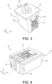
- An illustration of a small form factor printhead 30 is illustrated FIGs. 3 and 4 .
- the small form factor printhead 30 includes an ink reservoir body 32 having one or more sidewalls, such as four sidewalls 34a, 34b, 34c, 34d, and a bottom wall 34e.
- a cover 36 is attached to the four sidewalls 34a-34d to provide a closed ink reservoir within the ink reservoir body 32.
- the ink reservoir body has a cylindrical shape having a bottom wall and a cover. A variety of other shapes may be used for the ink reservoir body provided the shape of the reservoir body provides the small form factor described herein.
- the ink reservoir body 32 may be made of a variety of materials including, but not limited to, sintered powder metal, ceramic, nylon, polyethylene terephthalate (PET) and the like.
- Ink is supplied to the ink reservoir body 32 continuously or intermittently through an ink refill port 38 (ink reservoir refill port) attached to the cover 36.
- the cover 36 may also be made from a variety of materials including, but not limited to, sintered powder metal, ceramic, nylon, polybutylene terephthalate (PBT) and the like.
- the ink refill port 38 may have a barbed connector or a tube may be inserted through an opening in the cover 36 to provide the ink refill port 38.
- An underside 40 of the cover 36 is illustrated in FIG. 5 showing the ink refill port 38.
- An ejection head 42 is attached to the bottom wall 34e of the ink reservoir body 32.
- a flexible circuit 44 is electrically connected to the ejection head 42, and is attached to the bottom wall 34e and the side wall 34a to provide activation of the ejection head 42 during a printing operation.
- the ink reservoir body 32 has an internal ink volume ranging from about 4 mL to about 25 mL.
- the internal volume of the ink reservoir body 32 is devoid of any filter tower structure or any backpressure device. Accordingly, in some embodiments, the entire internal volume of the ink reservoir body 32 may be filled with ink as described in more detail below.
- an internal backpressure device such as foam, felt, a bladder, or other backpressure device may be included in the reservoir body 32, if desired.
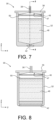
- a filter 46 ( FIG. 6 ) that is incorporated in the printhead 30 to prevent particles from clogging micro-scale flow features of the ejection head 42.
- the filter 46 is attached directly to a portion of the inside surface 47 of the cover 36 by an adhesive, by welding, or by heat staking the filter to a periphery of the inside surface of the cover 36.
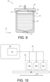
- the filter 46 is attached to the sidewalls 34a-34d of the ink reservoir body 32 opposite the bottom wall 34e, as illustrated in FIG. 9 by welding or by an adhesive.
- the ink reservoir body 32 is configured to provide a substantially increased amount of ink 48 in the ink reservoir body 32 above the ejection head 42 so that a ratio of ink 48 to vapor space 50 is increased.
- the printhead 30 can accommodate a larger volume of vapor without impeding the flow of ink to the ejection head 42 compared to the prior art printhead 10 which only has a relatively small volume of ink in the filter tower 16 adjacent to the ejection head 22.
- embodiments of the disclosure have an ink 48 to vapor space 50 ratio that is much greater than an ink to vapor space ratio provided by the conventional printhead 10. Having a larger ratio of ink 48 to vapor space 50 also improves cooling of the ejection head 42.
- a preferred ink to vapor space volume percent ranges from about 0 % to about 50 %.
- a surface area for filtering provided by the filter 46 may be substantially greater than a surface area provided by the prior art filter 14 since the filter 46 is not positioned on a filter tower 16 ( FIG. 1 ) as in the prior art printhead 10. Accordingly, refilling of the ink reservoir body 32 is enhanced by the unique design of the printhead 30 which allows for a larger volume of ink to be adjacent to the ejection head compared to the volume of ink in the filter tower 16 of the prior art printhead 10.
- the inside surface 47 of the cover may have a concave shape that is configured to allow a volume of ink 48 between the filter 46 and the cover 36 as shown in FIG. 9 .
- the filter 46 may be made of a variety of materials that are compatible with the ink. Accordingly, the filter 46 may be a stainless steel wire mesh filter, a PET track-etched membrane filter, a woven, non-woven, or random weave PET filter, or a polyethylene/polypropylene felt filter may be used. In some embodiments, an external filter attached to an ink refill supply line to the refill port 38 of the printhead 30 may be used instead of the internal filter 46 or in addition to the internal filter 46.
- FIG. 10 illustrates a continuous printer containing two or more stationary printheads 30 disposed above a substrate 60 moving in the direction of arrow 62.
- An ink supply conduit 64 provides a resupply of ink to the printheads 30a-30c from a bulk ink supply tank 66 located in a printer console 68.
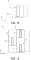
- each ejection head 42 has a swath length L1 (ejector array length) ranging from about 2 millimeters to about 25 millimeters.
- L1 swath length
- multiple printheads 30a-30c may be combined to give an overall swath length L2 that ranges from about 21 to about 60 millimeters or more as shown in FIG. 12 .
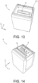
- an ejection head stiffener insert 70 may be attached to the bottom wall 34e as shown in FIGs. 13 and 14 . Both the bottom wall 34e and the stiffener insert 70 include an ink supply port 72 and 74, respectively, for providing ink to the ejection head 42.
- the stiffener insert 70 is made of ceramic. In other embodiments the stiffener insert 70 is made of an anodized aluminum or a metal that includes an inert coating to prevent flocculation of solids from fluids ejected by the ejection head 42.
- the stiffener insert 70 provides additional robustness to the ejection head 42 by limiting stresses caused by coefficient of thermal expansion (CTE) mismatch between the ejection head material and the reservoir body material, breakage caused by impact between the ejection head and a hard surface, and other forces that could result in a broken ejection head.
- CTE coefficient of thermal expansion
- the TIJ printhead 30 described herein provides a large volume of ink which allows for a longer printhead life resulting in fewer printer interruptions for maintenance. Also, the TIJ printhead has a small form factor without sacrificing the print swath provided by the printhead. By eliminating the filter tower and moving the ink filter to adjacent to the cover of the printhead, air handling problems are minimized which also provides for longer printhead life.
Landscapes
- Ink Jet (AREA)
Abstract
Description
- The disclosure is directed to an ejection head for high volume printing, and in particular to a continuous thermal inkjet printhead having improved vapor handling characteristics.
- For industrial printing applications, goods are typically marked continuously on the production line with indicia such as expiration dates, lot numbers, batch numbers, bar codes, and the like. This allows batch and production tracking of the goods. Product marking is particularly important in the food and pharmaceutical industries. However, the real estate area allotted to a production line in the food and pharmaceutical industries is typically limited and thus extremely valuable. Accordingly, it is advantageous to have the printing head or ink ejection device occupy limited space along the production line and to be positioned as close as possible to the substrate being marked.
- Continuous inkjet (CIJ) printers containing CIJ printheads are commonly used in high production industries due to their ability to be positioned close to the substrate without taking up much valuable real estate. However, CIJ printers are costly, require significant maintenance, and are limited in the resolution and quality of the printed images. Most CIJ printheads provide dot matrix indicia with very low image resolution such as 50 to 170 dots per inch (dpi).
- Thermal inkjet (TIJ) printheads are also commonly used in various industrial printing applications. TIJ printheads are typically less costly than CIJ printheads, provide much higher print resolution than CIJ printheads, such as up to 2400 dpi or more and are more easily replaced or maintained compared to CIJ printheads. However, conventional TIJ printheads are typically bulkier than the corresponding CIJ printheads and as such require more valuable space along the production line than the CIJ printheads. This makes the use of conventional TIJ printheads less desirable for use in the food and pharmaceutical industries.
- In order for a TIJ printhead to function continuously and efficiently in a high production setting, air management within the TIJ printhead is vital. Excessive vapor accumulating within the fluid reservoir body of the conventional TIJ printhead adjacent to the fluid ejection head is frequently the cause of poor printing performance, maintenance downtime, and/or failure of the TIJ printhead. A
conventional TIJ printhead 10 is illustrated inFIGs 1 and 2 and includes anink reservoir body 12. Theprinthead 10 also includes afilter 14 attached to afilter tower 16 as well as abackpressure device 18. Thebackpressure device 18 is in fluid contact with thefilter 14 to provide flow ofink 20 to anejection head 22. Accordingly, as shown inFIGs. 1 and 2 theprior art printhead 10 has only a small volume ofink 20 located in thefilter tower 16 that is adjacent to theejection head 22. The small volume ofink 20 in thefilter tower 16 is readily replenished from the ink impregnatedbackpressure device 18, such as a foam or felt, disposed in theink reservoir body 12. Thebackpressure device 18 prevents drooling of ink from theejection head 22 by maintaining a backpressure on the ink that flows through thefilter 14 into thefilter tower 16. Because of the small volume of ink in thefilter tower 16, under continuous printing operations, a vapor space is likely to accumulate in thefilter tower 16 impeding the flow of ink from thebackpressure device 18 through the filter andfilter tower 16 and into theejection head 22. - Another disadvantage of the
prior art printhead 10 for a continuous TIJ printing is the rather large size of theprinthead 10 relative to the size of the printhead for CIJ printing. Reducing the size or bulkiness of the TIJprinthead 10 would only result in a smaller volume of ink in thereservoir body 12 without improving an ink to vapor ratio within the printhead thus leading to increased air management problems. Accordingly, what is needed is a small form factor TIJ printhead that has improved air management properties during continuous printing operations. - In view of foregoing, an embodiment of the disclosure provides a small form factor printhead. The printhead includes an ink reservoir body having four sidewalls connected to a bottom wall. An ink supply port is disposed in the bottom wall. An ejection head is attached to an exterior surface of the bottom wall, wherein the ejection head is in ink flow communication with the ink supply port. A flexible circuit is electrically connected to the ejection head and is attached to the exterior surface of the bottom wall and an exterior surface of one of the four sidewalls. A cover is attached to a distal end of the four sidewalls opposite the bottom wall. A filter is attached adj acent to an underside of the cover.
- In some embodiments, an ink reservoir refill port is disposed in the cover.
- In some embodiments, the filter is adhesively attached to an inside surface of the cover. In some embodiments, the filter is attached to the four sidewalls opposite the bottom wall. In other embodiments, the filter is welded to an inside surface of the cover.
- In some embodiments, the filter is selected from a stainless steel mesh, a porous membrane, a random weave polymeric web, a mesh polymeric web, and a polymeric felt.
- In some embodiments, the ink reservoir body is devoid of a backpressure device. In other embodiments, the ink reservoir body is devoid of a filter tower structure.
- In some embodiments, the ink reservoir body has a total ink volume ranging from about 4 mL to about 25 mL.
- In some embodiments, the ejection head has an ejector array length ranging from about 2 millimeters to about 25 millimeters.
- In another embodiment there is provided a thermal inkjet printer. The thermal inkjet printer includes a small form factor printhead having an ink reservoir body having four sidewalls connected to a bottom wall, an ink supply port in the bottom wall, an ejection head attached to an exterior surface of the bottom wall, wherein the ejection head is in ink flow communication with the ink supply port, a flexible circuit electrically connected to the ejection head and attached to the exterior surface of the bottom wall and an exterior surface of one of the four sidewalls, a cover attached to a distal end of the four sidewalls opposite the bottom wall, a filter attached adjacent to an underside of the cover, and a ink reservoir refill port attached to an exterior surface of the cover. The thermal inkjet printer also includes a bulk ink supply tank in fluid flow communication with the ink reservoir refill port and a printhead controller in electrical communication with the small form factor printhead.
- In some embodiments, the thermal inkjet printer further includes: two or more stationary small form factor printheads adjacent to a movable substrate, wherein the two or more stationary small form factor printheads are configured for printing on the movable substrate.
- In some embodiments, each of the two or more stationary small form factor printheads have an ink reservoir having a total ink volume ranging from about 4 mL to about 25 mL.
- In some embodiments, each of the two or more stationary small form factor printheads has an ejector array length ranging from about 2 millimeters to about 25 millimeters.
- In some embodiments, the filter is selected from the group consisting of a stainless steel mesh, a porous membrane, a random weave polymeric web, a mesh polymeric web, and a polymeric felt.
- In another embodiment there is provided a small form factor printhead having an ink reservoir body having an internal void volume ranging from about 4 mL to about 25 mL. A top cover is attached to the ink reservoir body, wherein the top cover has a fluid fill port therein. A bottom wall is attached to the ink reservoir body on a distal end of the ink reservoir body from the top cover. The bottom wall has an ink supply port therein. An ejection head is attached to an exterior surface of the bottom wall. The ejection head is in ink flow communication with the ink supply port. A flexible circuit is electrically connected to the ejection head and attached to an exterior surface of the ink reservoir body. A filter is attached adjacent to an underside of the top cover.
- An advantage of the disclosed embodiments is that a much smaller ink reservoir may be provided without reducing the effectiveness of the air management system within the ink reservoir. Accordingly, even in the absence of a backpressure device within the ink reservoir body, a continuous flow of ink to the ejection head is provided by relocating the ink filter to adjacent to the cover so that the entire ink reservoir can effectively be filled with ink. Thus, a filter tower structure adjacent to an ink feed slot of the ejection head is not needed for the small form factor printhead disclosed herein. Other benefits and advantages may be evident by reference to the attached drawings in combination with the following detailed description.
-
-
FIG. 1 is a cross-sectional, side view, not to scale, of a prior art printhead. -
FIG. 2 is a cross-sectional, front view, not to scale of the printhead ofFIG. 1 . -
FIG. 3 is a top perspective view of a TIJ printhead according to an embodiment of the disclosure. -
FIG. 4 is a bottom perspective view of the TIJ printhead ofFIG. 3 . -
FIG. 5 is an underside plan view of a cover for the TIJ printhead ofFIG. 3 . -
FIG. 6 is a plan view of a filter attached to the underside of the cover ofFIG. 5 . -
FIG. 7 is a front cross-sectional view, not to scale, of the TIJ printhead ofFIG. 3 . -
FIG. 8 is a side cross-sectional view, not to scale, of the TIJ printhead ofFIG. 3 . -
FIG. 9 is a front cross-sectional view, not to scale, of a TIJ printhead according to another embodiment of the disclosure. -
FIG. 10 is a schematic illustration of a continuous inkjet printer containing multiple TIG printheads according to an embodiment of the disclosure. -
FIG. 11 is a bottom plan view, not to scale, of a TIJ printhead according to an embodiment of the disclosure. -
FIG. 12 is a bottom plan view, not to scale, of multiple TIJ printheads according to an embodiment of the disclosure. -
FIG. 13 is a bottom perspective view of an ink reservoir body for a TIJ printhead according to the disclosure. -
FIG. 14 is a bottom perspective view of the ink reservoir body ofFIG. 13 containing a stiffener insert according to an embodiment of the disclosure. - For the purposes of this disclosure, the term "small form factor" refers to an ink reservoir body having an internal void volume that is sufficient to hold from about 4 mL to about 25 mL or more of ink in the absence of a backpressure device and/or filter tower structure. The term "printhead" as used herein refers to the ink reservoir body having an ejection head, a flexible circuit attached to the ejection head, a cover for the reservoir body, an internal filter attached adjacent to the cover, and an ink refill port in the cover. The term "thermal inkjet (TIJ) printer" refers to a printer console having an ink supply reservoir therein, a conduit for providing ink to the printhead from the ink supply reservoir and a controller for activating the printhead. An illustration of a small
form factor printhead 30 is illustratedFIGs. 3 and 4 . - The small
form factor printhead 30 includes anink reservoir body 32 having one or more sidewalls, such as foursidewalls bottom wall 34e. Acover 36 is attached to the foursidewalls 34a-34d to provide a closed ink reservoir within theink reservoir body 32. In some embodiments, the ink reservoir body has a cylindrical shape having a bottom wall and a cover. A variety of other shapes may be used for the ink reservoir body provided the shape of the reservoir body provides the small form factor described herein. Theink reservoir body 32 may be made of a variety of materials including, but not limited to, sintered powder metal, ceramic, nylon, polyethylene terephthalate (PET) and the like. Ink is supplied to theink reservoir body 32 continuously or intermittently through an ink refill port 38 (ink reservoir refill port) attached to thecover 36. Thecover 36 may also be made from a variety of materials including, but not limited to, sintered powder metal, ceramic, nylon, polybutylene terephthalate (PBT) and the like. Theink refill port 38 may have a barbed connector or a tube may be inserted through an opening in thecover 36 to provide theink refill port 38. Anunderside 40 of thecover 36 is illustrated inFIG. 5 showing theink refill port 38. Anejection head 42 is attached to thebottom wall 34e of theink reservoir body 32. Aflexible circuit 44 is electrically connected to theejection head 42, and is attached to thebottom wall 34e and theside wall 34a to provide activation of theejection head 42 during a printing operation. - The overall size of the
ink reservoir body 32 is reduced compared to aconventional TIJ printhead 10 in order to allow just enough area for theejection head 42 andflexible circuit 44 to be attached to theink reservoir body 32 as shown inFIG. 4 . In some embodiments, theink reservoir body 32 has an internal ink volume ranging from about 4 mL to about 25 mL. In some embodiments the internal volume of theink reservoir body 32 is devoid of any filter tower structure or any backpressure device. Accordingly, in some embodiments, the entire internal volume of theink reservoir body 32 may be filled with ink as described in more detail below. In other embodiments, an internal backpressure device such as foam, felt, a bladder, or other backpressure device may be included in thereservoir body 32, if desired. - An important feature of the small
form factor printhead 30 is placement of a filter 46 (FIG. 6 ) that is incorporated in theprinthead 30 to prevent particles from clogging micro-scale flow features of theejection head 42. In one embodiment, illustrated inFIGs. 6-8 , thefilter 46 is attached directly to a portion of theinside surface 47 of thecover 36 by an adhesive, by welding, or by heat staking the filter to a periphery of the inside surface of thecover 36. In another embodiment, thefilter 46 is attached to thesidewalls 34a-34d of theink reservoir body 32 opposite thebottom wall 34e, as illustrated inFIG. 9 by welding or by an adhesive. Regardless of how thefilter 46 is attached to theprinthead 30, it is evident that theink reservoir body 32 is configured to provide a substantially increased amount ofink 48 in theink reservoir body 32 above theejection head 42 so that a ratio ofink 48 tovapor space 50 is increased. Thus, theprinthead 30 can accommodate a larger volume of vapor without impeding the flow of ink to theejection head 42 compared to theprior art printhead 10 which only has a relatively small volume of ink in thefilter tower 16 adjacent to theejection head 22. Accordingly, embodiments of the disclosure have anink 48 tovapor space 50 ratio that is much greater than an ink to vapor space ratio provided by theconventional printhead 10. Having a larger ratio ofink 48 tovapor space 50 also improves cooling of theejection head 42. A preferred ink to vapor space volume percent ranges from about 0 % to about 50 %. - Another important feature of the
filter 46 is that a surface area for filtering provided by thefilter 46 may be substantially greater than a surface area provided by theprior art filter 14 since thefilter 46 is not positioned on a filter tower 16 (FIG. 1 ) as in theprior art printhead 10. Accordingly, refilling of theink reservoir body 32 is enhanced by the unique design of theprinthead 30 which allows for a larger volume of ink to be adjacent to the ejection head compared to the volume of ink in thefilter tower 16 of theprior art printhead 10. In the embodiments wherein thefilter 46 is attached to theinside surface 47 of thecover 36, or to thesidewalls 34a-34d, theinside surface 47 of the cover may have a concave shape that is configured to allow a volume ofink 48 between thefilter 46 and thecover 36 as shown inFIG. 9 . - In the embodiments described above, the
filter 46 may be made of a variety of materials that are compatible with the ink. Accordingly, thefilter 46 may be a stainless steel wire mesh filter, a PET track-etched membrane filter, a woven, non-woven, or random weave PET filter, or a polyethylene/polypropylene felt filter may be used. In some embodiments, an external filter attached to an ink refill supply line to therefill port 38 of theprinthead 30 may be used instead of theinternal filter 46 or in addition to theinternal filter 46. -
FIG. 10 illustrates a continuous printer containing two or morestationary printheads 30 disposed above asubstrate 60 moving in the direction ofarrow 62. Anink supply conduit 64 provides a resupply of ink to theprintheads 30a-30c from a bulk ink supply tank 66 located in aprinter console 68. - As shown in
FIG. 11 , eachejection head 42 has a swath length L1 (ejector array length) ranging from about 2 millimeters to about 25 millimeters. In order to increase the swath length,multiple printheads 30a-30c may be combined to give an overall swath length L2 that ranges from about 21 to about 60 millimeters or more as shown inFIG. 12 . - It will be appreciated that there is a practical limit to the size of the
ejection head 42. Larger ejection heads 42 tend to be more prone to breakage during the manufacturing process and in use. Accordingly, in some embodiments, an ejectionhead stiffener insert 70 may be attached to thebottom wall 34e as shown inFIGs. 13 and 14 . Both thebottom wall 34e and thestiffener insert 70 include anink supply port ejection head 42. In some embodiments, thestiffener insert 70 is made of ceramic. In other embodiments thestiffener insert 70 is made of an anodized aluminum or a metal that includes an inert coating to prevent flocculation of solids from fluids ejected by theejection head 42. Thestiffener insert 70 provides additional robustness to theejection head 42 by limiting stresses caused by coefficient of thermal expansion (CTE) mismatch between the ejection head material and the reservoir body material, breakage caused by impact between the ejection head and a hard surface, and other forces that could result in a broken ejection head. - The
TIJ printhead 30 described herein provides a large volume of ink which allows for a longer printhead life resulting in fewer printer interruptions for maintenance. Also, the TIJ printhead has a small form factor without sacrificing the print swath provided by the printhead. By eliminating the filter tower and moving the ink filter to adjacent to the cover of the printhead, air handling problems are minimized which also provides for longer printhead life. - For the purposes of this specification and appended claims, unless otherwise indicated, all numbers expressing quantities, percentages or proportions, and other numerical values used in the specification and claims, are to be understood as being modified in all instances by the term "about." Accordingly, unless indicated to the contrary, the numerical parameters set forth in the following specification and attached claims are approximations that can vary depending upon the desired properties sought to be obtained by the present disclosure. At the very least, and not as an attempt to limit the application of the doctrine of equivalents to the scope of the claims, each numerical parameter should at least be construed in light of the number of reported significant digits and by applying ordinary rounding techniques.
- While particular embodiments have been described, alternatives, modifications, variations, improvements, and substantial equivalents that are or can be presently unforeseen can arise to applicants or others skilled in the art. Accordingly, the appended claims as filed and as they can be amended are intended to embrace all such alternatives, modifications, variations, improvements, and substantial equivalents.
Claims (20)
- A small form factor printhead (30, 30a, 30b, 30c), characterized in that comprising;an ink reservoir body (32), having four sidewalls (34a, 34b, 34c, 34d) connected to a bottom wall (34e);an ink supply port (72, 74) in the bottom wall (34e);an ejection head (42), attached to an exterior surface of the bottom wall (34e), wherein the ejection head (42) is in ink flow communication with the ink supply port (72, 74);a flexible circuit (44), electrically connected to the ejection head (42) and attached to the exterior surface of the bottom wall (34e) and an exterior surface of one of the four sidewalls (34a, 34b, 34c, 34d);a cover (36), attached to a distal end of the four sidewalls (34a, 34b, 34c, 34d) opposite the bottom wall (34e); anda filter (46), attached adjacent to an underside of the cover (36).
- The small form factor printhead (30, 30a, 30b, 30c) of claim 1, further comprising:
an ink reservoir refill port (38), being disposed in the cover (36). - The small form factor printhead (30, 30a, 30b, 30c) of claim 1, wherein
The filter (46) is adhesively attached to an inside surface of the cover (36). - The small form factor printhead (30, 30a, 30b, 30c) of claim 1, wherein
the filter (46) is welded to an inside surface of the cover (36). - The small form factor printhead (30, 30a, 30b, 30c) of claim 1, wherein
the filter (46) is attached to the four sidewalls (34a, 34b, 34c, 34d) opposite the bottom wall (34e). - The small form factor printhead (30, 30a, 30b, 30c) of claim 1, wherein
the filter (46) is selected from the group consisting of a stainless steel mesh, a porous membrane, a random weave polymeric web, a mesh polymeric web, and a polymeric felt. - The small form factor printhead (30, 30a, 30b, 30c) of claim 1, wherein
the ink reservoir body is devoid of a backpressure device. - The small form factor printhead (30, 30a, 30b, 30c) of claim 1, wherein
the ink reservoir body is devoid of a filter tower structure. - The small form factor printhead (30, 30a, 30b, 30c) of claim 1, wherein
the ink reservoir body has a total ink volume ranging from about 4 mL to about 25 mL. - The small form factor printhead (30, 30a, 30b, 30c) of claim 1, wherein
the ejection head (42) has an ejector array length (L1) ranging from about 2 millimeters to about 25 millimeters. - A thermal inkjet printer, characterized in that comprising;a small form factor printhead (30, 30a, 30b, 30c), having:an ink reservoir body (32) having four sidewalls (34a, 34b, 34c, 34d) connected to a bottom wall (34e),an ink supply port (72, 74) in the bottom wall (34e),an ejection head (42) attached to an exterior surface of the bottom wall (34e), wherein the ejection head (42) is in ink flow communication with the ink supply port (72, 74),a flexible circuit (44) electrically connected to the ejection head (42) and attached to the exterior surface of the bottom wall (34e) and an exterior surface of one of the four sidewalls (34a, 34b, 34c, 34d),a cover (36) attached to a distal end of the four sidewalls (34a, 34b, 34c, 34d) opposite the bottom wall (34e),a filter (46) attached adjacent to an underside of the cover (36), andan ink reservoir refill port (38) attached to an exterior surface of the cover (36);a bulk ink supply tank (66) in fluid flow communication with the ink reservoir refill port (38); anda printhead controller (68) in electrical communication with the small form factor printhead (30, 30a, 30b, 30c).
- The thermal inkjet printer of claim 11, further comprising:two or more stationary small form factor printheads (30, 30a, 30b, 30c) adjacent to a movable substrate,wherein the two or more stationary small form factor printheads (30, 30a, 30b, 30c) are configured for printing on the movable substrate.
- The thermal inkjet printer of claim 12, wherein
each of the two or more stationary small form factor printheads (30, 30a, 30b, 30c) have an ink reservoir having a total ink volume ranging from about 4 mL to about 25 mL. - The thermal inkjet printer of claim 12, wherein
each of the two or more stationary small form factor printheads (30, 30a, 30b, 30c) has an ejector array length (L1) ranging from about 2 millimeters to about 25 millimeters. - The thermal inkjet printer of claim 11, wherein
the filter (46) is selected from the group consisting of a stainless steel mesh, a porous membrane, a random weave polymeric web, a mesh polymeric web, and a polymeric felt. - A small form factor printhead (30, 30a, 30b, 30c) comprising:an ink reservoir body (32), having an internal void volume ranging from about 4 mL to about 25 mL;a top cover (36), attached to the ink reservoir body (32), the top cover (36) having a fluid fill port therein;a bottom wall (34e), attached to the ink reservoir body (32) on a distal end of the ink reservoir body (32) from the top cover (36), the bottom wall (34e) having an ink supply port (72, 74) therein;an ejection head (42), attached to an exterior surface of the bottom wall (34e), wherein the ejection head (42) is in ink flow communication with the ink supply port (72, 74);a flexible circuit (44) electrically connected to the ejection head (42) and attached to an exterior surface of the ink reservoir body (32); anda filter (46) attached adjacent to an underside of the top cover (36).
- The small form factor printhead (30, 30a, 30b, 30c) of claim 16, wherein
the filter (46) is welded to an inside surface of the top cover (36). - The small form factor printhead (30, 30a, 30b, 30c) of claim 16, wherein
the filter (46) is selected from the group consisting of a stainless steel mesh, a porous membrane, a random weave polymeric web, a mesh polymeric web, and a polymeric felt. - The small form factor printhead (30, 30a, 30b, 30c) of claim 16, wherein
the ink reservoir body is devoid of a backpressure device. - The small form factor printhead (30, 30a, 30b, 30c) of claim 16, wherein
the ink reservoir body is devoid of a filter tower structure.
Applications Claiming Priority (1)
| Application Number | Priority Date | Filing Date | Title |
|---|---|---|---|
| US18/171,478 US20240278580A1 (en) | 2023-02-20 | 2023-02-20 | Small form factor print head and printer |
Publications (1)
| Publication Number | Publication Date |
|---|---|
| EP4417430A1 true EP4417430A1 (en) | 2024-08-21 |
Family
ID=89474668
Family Applications (1)
| Application Number | Title | Priority Date | Filing Date |
|---|---|---|---|
| EP24150558.5A Withdrawn EP4417430A1 (en) | 2023-02-20 | 2024-01-05 | Small form factor printhead and thermal inkjet printer |
Country Status (4)
| Country | Link |
|---|---|
| US (1) | US20240278580A1 (en) |
| EP (1) | EP4417430A1 (en) |
| JP (1) | JP2024118433A (en) |
| CN (1) | CN118514426A (en) |
Citations (4)
| Publication number | Priority date | Publication date | Assignee | Title |
|---|---|---|---|---|
| EP0875385A2 (en) * | 1997-04-30 | 1998-11-04 | Hewlett-Packard Company | An ink delivery that utilizes a separate insertable filter carrier |
| US20080291253A1 (en) * | 2007-05-23 | 2008-11-27 | Marc Frazier Baker | Ink Jet Printhead Cartridge Having An Ink Fill Access Port In Fluid Communication With The Filter Tower |
| US20170096012A1 (en) * | 2014-05-30 | 2017-04-06 | Funai Electric Co., Ltd. | Printhead assembly |
| US20220226828A1 (en) * | 2021-01-20 | 2022-07-21 | Funai Electric Co., Ltd. | Pipette-Fillable Cartridge |
Family Cites Families (6)
| Publication number | Priority date | Publication date | Assignee | Title |
|---|---|---|---|---|
| US6193363B1 (en) * | 1999-04-27 | 2001-02-27 | Hewlett-Packard Company | Ink jet printing apparatus with air purge function |
| JP5078548B2 (en) * | 2007-10-26 | 2012-11-21 | キヤノン株式会社 | Discharging device and recording device |
| JP4948370B2 (en) * | 2007-11-22 | 2012-06-06 | キヤノン株式会社 | Recording head and recording apparatus |
| US8523327B2 (en) * | 2010-02-25 | 2013-09-03 | Eastman Kodak Company | Printhead including port after filter |
| US8807718B2 (en) * | 2012-11-28 | 2014-08-19 | Eastman Kodak Company | Pressure regulated inkjet printhead with replaceable on-axis ink tank |
| WO2017208776A1 (en) * | 2016-06-03 | 2017-12-07 | コニカミノルタ株式会社 | Inkjet recording device |
-
2023
- 2023-02-20 US US18/171,478 patent/US20240278580A1/en not_active Abandoned
-
2024
- 2024-01-04 CN CN202410010112.9A patent/CN118514426A/en active Pending
- 2024-01-05 EP EP24150558.5A patent/EP4417430A1/en not_active Withdrawn
- 2024-01-26 JP JP2024009866A patent/JP2024118433A/en active Pending
Patent Citations (4)
| Publication number | Priority date | Publication date | Assignee | Title |
|---|---|---|---|---|
| EP0875385A2 (en) * | 1997-04-30 | 1998-11-04 | Hewlett-Packard Company | An ink delivery that utilizes a separate insertable filter carrier |
| US20080291253A1 (en) * | 2007-05-23 | 2008-11-27 | Marc Frazier Baker | Ink Jet Printhead Cartridge Having An Ink Fill Access Port In Fluid Communication With The Filter Tower |
| US20170096012A1 (en) * | 2014-05-30 | 2017-04-06 | Funai Electric Co., Ltd. | Printhead assembly |
| US20220226828A1 (en) * | 2021-01-20 | 2022-07-21 | Funai Electric Co., Ltd. | Pipette-Fillable Cartridge |
Also Published As
| Publication number | Publication date |
|---|---|
| CN118514426A (en) | 2024-08-20 |
| JP2024118433A (en) | 2024-08-30 |
| US20240278580A1 (en) | 2024-08-22 |
Similar Documents
| Publication | Publication Date | Title |
|---|---|---|
| KR100460242B1 (en) | Pressure adjustment chamber, ink-jet recording head having the same, and ink-jet recording device using the same | |
| US5657065A (en) | Porous medium for ink delivery systems | |
| JP3813208B2 (en) | Matrix pen array for inkjet printing | |
| EP0931662B1 (en) | Ink-jet printer and method of controlling the same | |
| US20090273637A1 (en) | Liquid ejection head | |
| CN105939863B (en) | Three-colour ink cartridge housing | |
| JP3122230B2 (en) | Ink supply mechanism | |
| EP0953449A1 (en) | Inkjet ink container and containment using particles for backpressure transition | |
| US20240278580A1 (en) | Small form factor print head and printer | |
| US7540587B2 (en) | Liquid passage forming member guiding device | |
| JP4817954B2 (en) | Inkjet recording device | |
| US9815290B2 (en) | Tri-color ink cartridge | |
| US20070046743A1 (en) | Ink container | |
| US7201476B2 (en) | Inkjet printhead with bubble handling properties | |
| JP5087682B2 (en) | Parts for injecting fluid | |
| JPH08281927A (en) | Recording head, recording apparatus using the recording head, and recording method using the recording head | |
| JPH081956A (en) | Ink jet recording device | |
| US7396109B2 (en) | Inkjet printing system with high drop-weight yellow | |
| US8029117B2 (en) | Selectable fill volume for ink reservoir | |
| JP4454911B2 (en) | Liquid discharge head and image forming apparatus using the same | |
| US20250033368A1 (en) | Liquid container and liquid consumption apparatus | |
| US12350934B2 (en) | Liquid ejection head and liquid ejection apparatus | |
| US20030142174A1 (en) | Baffles to protect inkjet printheads by capturing contaminants, and method | |
| JP4630575B2 (en) | Recording head unit and ink jet recording apparatus | |
| US12168353B2 (en) | Unified bulk ink cartridge for thermal inkjet printer |
Legal Events
| Date | Code | Title | Description |
|---|---|---|---|
| PUAI | Public reference made under article 153(3) epc to a published international application that has entered the european phase |
Free format text: ORIGINAL CODE: 0009012 |
|
| STAA | Information on the status of an ep patent application or granted ep patent |
Free format text: STATUS: THE APPLICATION HAS BEEN PUBLISHED |
|
| AK | Designated contracting states |
Kind code of ref document: A1 Designated state(s): AL AT BE BG CH CY CZ DE DK EE ES FI FR GB GR HR HU IE IS IT LI LT LU LV MC ME MK MT NL NO PL PT RO RS SE SI SK SM TR |
|
| STAA | Information on the status of an ep patent application or granted ep patent |
Free format text: STATUS: REQUEST FOR EXAMINATION WAS MADE |
|
| 17P | Request for examination filed |
Effective date: 20240828 |
|
| RBV | Designated contracting states (corrected) |
Designated state(s): AL AT BE BG CH CY CZ DE DK EE ES FI FR GB GR HR HU IE IS IT LI LT LU LV MC ME MK MT NL NO PL PT RO RS SE SI SK SM TR |
|
| STAA | Information on the status of an ep patent application or granted ep patent |
Free format text: STATUS: THE APPLICATION HAS BEEN WITHDRAWN |
|
| 18W | Application withdrawn |
Effective date: 20241126 |
|
| 19U | Interruption of proceedings before grant |
Effective date: 20241024 |